EP3244237A1 - Optical sensor - Google Patents
Optical sensor Download PDFInfo
- Publication number
- EP3244237A1 EP3244237A1 EP16168964.1A EP16168964A EP3244237A1 EP 3244237 A1 EP3244237 A1 EP 3244237A1 EP 16168964 A EP16168964 A EP 16168964A EP 3244237 A1 EP3244237 A1 EP 3244237A1
- Authority
- EP
- European Patent Office
- Prior art keywords
- transmitter
- receiver
- optical sensor
- light
- sensor according
- Prior art date
- Legal status (The legal status is an assumption and is not a legal conclusion. Google has not performed a legal analysis and makes no representation as to the accuracy of the status listed.)
- Granted
Links
- 230000003287 optical effect Effects 0.000 title claims abstract description 61
- 238000011157 data evaluation Methods 0.000 claims abstract description 22
- 238000011156 evaluation Methods 0.000 claims description 35
- 238000000034 method Methods 0.000 claims description 11
- 238000012544 monitoring process Methods 0.000 claims description 8
- 230000001360 synchronised effect Effects 0.000 claims description 4
- 230000015572 biosynthetic process Effects 0.000 claims description 2
- 230000001419 dependent effect Effects 0.000 claims description 2
- 108091026890 Coding region Proteins 0.000 claims 1
- 230000005540 biological transmission Effects 0.000 description 22
- 238000001514 detection method Methods 0.000 description 12
- 230000004888 barrier function Effects 0.000 description 7
- 238000010586 diagram Methods 0.000 description 3
- 230000002123 temporal effect Effects 0.000 description 2
- 230000006978 adaptation Effects 0.000 description 1
- 238000011161 development Methods 0.000 description 1
- 230000018109 developmental process Effects 0.000 description 1
- 230000004069 differentiation Effects 0.000 description 1
- 238000006073 displacement reaction Methods 0.000 description 1
- 230000000694 effects Effects 0.000 description 1
- 230000002452 interceptive effect Effects 0.000 description 1
- 230000007257 malfunction Effects 0.000 description 1
- 230000005855 radiation Effects 0.000 description 1
Images


Classifications
-
- G—PHYSICS
- G01—MEASURING; TESTING
- G01V—GEOPHYSICS; GRAVITATIONAL MEASUREMENTS; DETECTING MASSES OR OBJECTS; TAGS
- G01V8/00—Prospecting or detecting by optical means
- G01V8/10—Detecting, e.g. by using light barriers
Definitions
- the invention relates to an optical sensor and a method for operating an optical sensor.
- Such optical sensors can be designed in particular as light barriers or else as light barrier arrangements, in particular light curtains.
- these optical sensors have at least one transmitter and at least one receiver associated with this transmitter.
- the transmitter and receiver are always activated in given cycles in a timely manner.
- a data evaluation unit For the detection of objects in a monitoring area, it is checked in a data evaluation unit based on an evaluation of the received signals of the receiver whether a sequence of light pulses emitted by the transmitter is received. If this is the case, there is a free surveillance area. Otherwise, there is an object intervention. Depending on this evaluation, a binary switching signal is generated in the data evaluation unit whose switching states indicate whether or not an object is in the monitored area.
- optical sensors in addition to object detection, external light detection takes place. This is used in particular during the commissioning of the optical sensor in order to provide suitable countermeasures in the event of such external light irradiation.
- the DE 42 24 784 C2 relates to a method for operating light barriers, light curtains or light curtains, in which a transmitter within a predetermined first time window at least two temporally in a second and at least a third time window lying pulse groups encoded light emitted to an associated receiver.
- the second and the at least third time windows are at a distance from one another and lie asymmetrically within the first time window.
- the receiver only checks during the second and the at least third time window whether pulse groups received within these time slots have a valid code. The receiver then generates a signal for trouble-free operation if a received pulse group has already been recognized as valid.
- the invention has for its object to provide an optical sensor and a method with improved extraneous light detection.
- the invention relates to an optical sensor with at least one transmitter, at least one receiver and a data evaluation unit.
- the data evaluation unit is checked by means of received at the output of the receiver receiving signals, whether a coding forming a sequence of emitted by the transmitter light pulses is registered in the receiver. Depending on this, a binary switching signal is generated.
- a synchronization unit is provided, by means of which the transmitter and receiver are activated synchronously in time within predetermined cycles. The light pulses emitted by the transmitter are inverted in different cycles and / or shifted in time.
- a Fremdlichtauspithim is provided, which evaluates the reception signals of the receiver for detecting extraneous light within a cycle only in the time intervals in which the transmitter no light pulses are emitted.
- the invention relates to a corresponding method.
- the basic idea of the invention thus lies in the fact that the transmitter of the optical sensor does not always emit the same light pulses in the cycles, ie time intervals in which it is activated. Rather, the light pulses are inverted and / or time-shifted in one cycle to the light pulses in a preceding cycle.
- an evaluation of the received signals for generating the binary switching signal for generating the binary switching signal is carried out on the one hand with the data evaluation unit. Parallel to this, a foreign light detection takes place in the external light evaluation unit by the received signals of the receiver are always evaluated only in the transmission pauses of the transmitter.
- the transmission times of the light pulses are varied within the cycles by investing and / or temporal displacement, the entire time interval of the cycle of the transmitter can be checked for the presence of extraneous light within a short time with the Fremdlichtauspitä.
- an error message is advantageously generated there, which allows the user to take countermeasures against the external light irradiation before malfunctioning of the optical sensor occurs.
- the extraneous light detection during commissioning of the optical sensor so that countermeasures can be taken in such a detection of external light irradiation, so that a fault-free operation of the optical sensor is ensured.
- the inventive method can be used for different optical sensors, wherein the optical sensor can be configured as a safety sensor, which is used in safety applications.
- the optical sensor may have only one transmitter and only one receiver and be designed as a light barrier, reflection light barrier or light scanner.
- optical sensor can also have multiple arrangements of transmitters and receivers.
- the optical sensor is particularly advantageously a light curtain which has a plurality of beam axes forming pairs of transmitters and receivers.
- the pairs are cyclically activated one after the other by transmitters and receivers by means of the synchronization unit.
- the transmitters and receivers can be arranged in different housings on opposite edges of a monitoring area.
- the transmitter and receiver are integrated in a housing, wherein a reflector unit is provided at a distance to this.
- the operation of the transmitter and receiver is synchronized such that only one transmitter and one receiver of a beam axis are activated in each cycle.
- the synchronization unit can carry out a wired synchronization, wherein the synchronization unit is connected via lines to control means for the transmitter (s) and the receiver (s).
- an optical synchronization takes place with the synchronization unit, wherein the coding formed by the light pulses of the transmitter or of a transmitter serves for the optical synchronization.
- the beam axis used for synchronization must have a coding that is different from the codings of all other beam axes.
- the light pulses of the individual beam axes different codes, so that any beam axis is used for synchronization.
- the light pulses are unchanged in predetermined sequences and then inverted and / or time-shifted within the cycle.
- extraneous light can be detected within the entire cycle with the extraneous light evaluation unit and, in particular, interfering radiation can also be detected which coincidentally corresponds to the transmission clock of the transmitter.
- the light pulses of the transmitter are mutually inverted and / or shifted in time.
- a cycle ensues in which the light pulses of this transmitter are inverted and / or shifted in time.
- the rate of change with which the transmission times of the light pulses are changed within the cycles are specified application specific, in particular an adaptation to certain extraneous light sources that generate interference with known frequencies, is possible.
- the amount of a temporal shift of light pulses within a cycle is constant or temporally variable.
- an evaluation of received signals over a plurality of cycles takes place in the data evaluation unit in order to generate the switching signal.
- the received signals of the receiver or receivers are evaluated in the data evaluation unit with a first threshold value.
- the received signals of the receiver (s) are evaluated with a second threshold value.
- the two threshold values can in particular be designed differently, so that the first threshold value can be adapted to the useful light level and the second threshold value can be adapted to the ambient light level.
- optical sensor When working according to the light barrier principle optical sensor while a free surveillance area is generally recognized by the fact that in the respective receiver emitted by the associated transmitter sequence of light pulses is detected. Accordingly, there is an object intervention in the monitoring area if the light pulses of the assigned transmitter are no longer received in the respective receiver.
- the external light evaluation unit current received signals are compared with a previously determined mean value of received signals.
- a differentiation of received extraneous light can be such that a noise caused for example by sunlight at the receiver of individual, sporadic interference signals can be distinguished.
- the external light evaluation unit has a counting device, by means of which results of extraneous light are counted.
- the frequency of external light irradiation can be detected, whereby a classification of extraneous light is possible.
- This classification can be expressed in the error message generated in the extraneous light evaluation unit.
- FIG. 1 shows an embodiment of the optical sensor 1 in the form of a through-beam sensor.
- This optical sensor 1 has in a first housing 2 to a light beam 3 emitting transmitter 4, the operation of which is controlled by control means, not shown.
- the transmitter 4 is formed by a light emitting diode or laser diode.
- the optical sensor 1 has a second housing 5, in which a receiver 6 with associated control means and evaluation means is integrated.
- the control means and evaluation means to a fail-safe, in particular redundant structure.
- the receiver 6 is formed by a photodiode or the like.
- the control means and evaluation means assigned to the receiver 6 are formed by a synchronization unit 7, a data evaluation unit 8 and a foreign light evaluation unit 9. These units can be designed as separate hardware units or as different software modules of a computer unit.
- the housing 2 with the transmitter 4 and the housing 5 with the receiver 6 are arranged on opposite sides of a monitoring area.
- the transmitter 4 emits pulse-shaped light beams 3.
- the transmitter 4 emits in cycles, that is, time intervals of predetermined length, which are separated by longer transmission pauses, consequences of light pulses that strike the receiver 6 with free monitoring range.
- an optical synchronization of the receiver 6 takes place on the transmitter 4.
- the light pulses emitted by the transmitter 4 are known as expectation to the forming a coding light pulses of the transmitter 4 in the synchronization unit 7.
- the operation of the receiver 6 so synchronized that the transmitter 4 and the receiver 6 are always activated at the same time, namely within the cycles in which the transmitter emits 4 light pulses.
- a binary switching signal is generated in response to the received signals registered at the receiver 6, which is output via a switching output, not shown. If, in the receiver 6, the coding emitted by the transmitter 4 is received in the form of the transmitted light pulses, there is a free surveillance area and the switching signal assumes a corresponding switching state "free surveillance area". If, however, the coding of the transmitter 4 is not detected in the receiver 6, there is an object intervention in the monitoring area. Then the switching signal assumes a corresponding switching state according to an object message.
- the switching signal it is expedient to evaluate the received signals with a threshold value. Furthermore, the received signals detected over several cycles can also be used to generate the switching signal.
- extraneous light evaluation unit 9 With the extraneous light evaluation unit 9, the detection of extraneous light, which can be radiated as interference signal from external light sources in the receivers 6 takes place. Such extraneous light beams 10 are in FIG. 1 shown.
- the optical sensor 1 For detecting such extraneous light during the entire cycle time in which the transmitter 4 emits light pulses, the optical sensor 1 according to FIG. 1 according to the in the FIGS. 2a-d operated method operated.
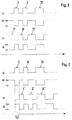
- FIG. 2a shows a first cycle in which the transmitter 4 emits three light pulses I, II, III, each preceded by a transmission break.
- Figure 2c shows a second cycle.
- the emitted light pulses I ', II', III ' are inverted to the light pulses I, II, III of the first cycle, that is, the light pulses of the second cycle correspond to the transmission pauses of the first cycle.
- the change between a transmission mode with the first cycle according to FIG. 2a and a transmission operation with the second cycle according to Figure 2c can be done alternately, so that the transmission mode is changed for each cycle.
- the transmission mode can be changed only after a predetermined or random number of cycles.
- we specified this transmission mode via the control means in the transmitter.
- FIG. 2b shows a release signal that in the transmission mode according to FIG. 2a is generated in the synchronization unit 7 and input to the extraneous light evaluation unit 9.
- the Figure 2d shows a release signal, which in the transmission mode according to Figure 2c is generated in the synchronization unit 7 and read into the Fremdlichtausensetician 9.
- the release signals control the external light detection in the extraneous light evaluation unit 9. Since then, when the transmitter 4 just emits a light pulse, no additional extraneous light can be detected, the control of the Fremdlichtausense elaborate 9 takes place with the enable signals such that in the Fremdlichtausenseiser 9 a Fremdlichtausificat only takes place when the respective enable signal, the signal value "high ", which is the case only in the transmission pauses of the transmitter 4.
- the external light detection is expediently carried out by an evaluation of the received signals with a threshold value, which preferably differs from the threshold value of the data evaluation unit 8 for generating the switching signal.
- the registered extraneous light in the extraneous light evaluation unit 9 can be averaged over a predetermined period of time, with subsequent current extraneous light irradiations being subsequently compared with the mean value. Constant extraneous light sources (such as sunlight) can thus be distinguished from rapidly changing noise spikes. Finally, extraneous light results can be counted in the external light evaluation unit 9 by means of a counting device.
- an error message is generated as a function of the external light detection in the external light evaluation unit 9, in particular if the extraneous light reaches a critical value.
- This error message can be displayed via a signal transmitter of the optical sensor 1.
- the detected extraneous light or the error message is taken into account in the data evaluation unit 8 during the generation of the switching signal.
- the results of the received signal evaluation over a number N of cycles can be used to generate the switching signal, wherein an object message is only generated if at least for a predetermined number M ( ⁇ N) cycles no extraneous light is registered.
- FIGS. 3a to 3d show a variant of the method according to the FIGS. 2a to 2d .
- the execution according to FIG. 3 are the light pulses I ', II', III 'according to Figure 3c according to the original light pulses I, II, III not inverted, but shifted by a time interval .DELTA.t.
- the time shift ⁇ t may be constant or chosen differently for different cycles.
- the evaluation is carried out in the extraneous light evaluation unit 9 on the basis of the enable signals according to FIGS FIGS. 3b, 3d analogous to the embodiment according to FIG. 2 ,
- FIG. 4 shows an embodiment of the optical sensor 1 in the form of a light curtain.
- the light curtain comprises a plurality of light beams 3 emitting transmitter 4 in a first housing 2 at a first edge of the surveillance area and a plurality of light beams 3 receiving receiver 6 in a second housing 5 at a second edge of the surveillance area.
- the transmitters 4 are controlled by a control means, not shown.
- the receivers 6 are connected to control and evaluation means, the embodiment of the FIG. 1 that is, they include a synchronization unit 7, a data evaluation unit 8 and a Fremdlichtausensemother 9.
- control and evaluation means the embodiment of the FIG. 1 that is, they include a synchronization unit 7, a data evaluation unit 8 and a Fremdlichtausensemother 9.
- the optical sensor 1 according to FIG. 1 can also be the optical sensor 1 according to FIG. 4 be designed as a security sensor.
- Each sensor is assigned to form a beam axis, a receiver 6, so that in free surveillance area, as in FIG. 4 illustrated, the light beams 3 of the transmitter 4 meet only the associated receiver 6.
- the transmitters 4 are cyclically activated one after the other.
- the transmitters 4 each emit codings forming light pulses in one cycle.
- FIG. 5 for the first three transmitters 4 shows by way of example, send all transmitters 4 different codings (in FIG. 5 for the first three transmitters 4 with a, b, c denotes).
- the synchronization of the receiver 6 to the transmitter 4 is again carried out optically via the synchronization unit 7, analogous to the embodiment according to FIG. 1 ,
- the coding of a beam axis is used for synchronization in the present case. Since all codings clearly differ from each other, any beam axis can be used for synchronization.
- the evaluation of the beam axes in the data evaluation unit 8 takes place such that a switching signal with the switching state "free monitoring area" is only generated if the light pulses of the respective transmitter 4 are registered in the associated receiver 6 for all beam axes.
- a switching state of the switching signal corresponding to an object message is then obtained if at least the light beams 3 of a beam axis are interrupted by an object intervention.
- the external light detection in the light curtain according to FIG. 4 takes place analogously to the optical sensor 1 according to FIG. 1 with the extension to the effect that for each beam axis an error evaluation according to the method of FIG. 2 or 3 he follows.
Abstract
Die Erfindung betrifft einen optischen Sensor (1) mit wenigstens einem Sender (4), wenigstens einem Empfänger (6) und einer Datenauswerteeinheit (8). In der Datenauswerteeinheit (8) wird anhand von am Ausgang des Empfängers (6) anstehenden Empfangssignalen geprüft, ob eine eine Codierung bildende Folge von vom Sender (4) emittierten Lichtpulsen im Empfänger (6) registriert wird. Abhängig hiervon wird ein binäres Schaltsignal generiert. Eine Synchronisationseinheit (7) ist vorgesehen, mittels derer der Sender (4) und Empfänger (6) zeitlich synchron innerhalb vorgegebener Zyklen aktiviert sind. Die vom Sender (4) emittierten Lichtpulse sind in verschiedenen Zyklen zueinander invertiert und/oder zeitlich verschoben. Eine Fremdlichtauswerteeinheit (8) ist vorgesehen, welche zur Erfassung von Fremdlicht innerhalb eines Zyklus nur in den Zeitintervallen, in welchen vom Sender (4) keine Lichtpulse emittiert werden, die Empfangssignale des Empfängers (6) auswertet.The invention relates to an optical sensor (1) having at least one transmitter (4), at least one receiver (6) and a data evaluation unit (8). In the data evaluation unit (8) it is checked on the basis of received at the output of the receiver (6) received signals whether a coding forming a sequence of emitted by the transmitter (4) light pulses in the receiver (6) is registered. Depending on this, a binary switching signal is generated. A synchronization unit (7) is provided by means of which the transmitter (4) and receiver (6) are activated synchronously in time within predetermined cycles. The light pulses emitted by the transmitter (4) are inverted and / or shifted in time in different cycles. A Fremdlichtauswerteeinheit (8) is provided, which for detecting extraneous light within a cycle only in the time intervals in which the transmitter (4) no light pulses are emitted, the received signals of the receiver (6) evaluates.
Description
Die Erfindung betrifft einen optischen Sensor sowie ein Verfahren zum Betrieb eines optischen Sensors.The invention relates to an optical sensor and a method for operating an optical sensor.
Derartige optische Sensoren können insbesondere als Lichtschranken oder auch als Lichtschrankenanordnungen, insbesondere Lichtvorhänge ausgebildet sein.Such optical sensors can be designed in particular as light barriers or else as light barrier arrangements, in particular light curtains.
Generell weisen diese optischen Sensoren wenigstens einen Sender und wenigstens einen Empfänger, der diesem Sender zugeordnet ist, auf. Dabei werden der Sender und Empfänger in vorgegebenen Zyklen immer zeitglich aktiviert.In general, these optical sensors have at least one transmitter and at least one receiver associated with this transmitter. In this case, the transmitter and receiver are always activated in given cycles in a timely manner.
Zur Erfassung von Objekten in einem Überwachungsbereich wird in einer Datenauswerteeinheit anhand einer Auswertung der Empfangssignale des Empfängers geprüft, ob eine vom Sender emittierte Folge von Lichtpulsen empfangen wird. Ist dies der Fall, liegt ein freier Überwachungsbereich vor. Andernfalls liegt ein Objekteingriff vor. Abhängig von dieser Auswertung wird in der Datenauswerteeinheit ein binäres Schaltsignal generiert, dessen Schaltzustände angeben, ob sich ein Objekt im Überwachungsbereich befindet oder nicht.For the detection of objects in a monitoring area, it is checked in a data evaluation unit based on an evaluation of the received signals of the receiver whether a sequence of light pulses emitted by the transmitter is received. If this is the case, there is a free surveillance area. Otherwise, there is an object intervention. Depending on this evaluation, a binary switching signal is generated in the data evaluation unit whose switching states indicate whether or not an object is in the monitored area.
Bei bekannten optischen Sensoren erfolgt zusätzlich zur Objekterfassung eine Fremdlichterfassung. Dies wird insbesondere bei der Inbetriebnahme des optischen Sensors genutzt, um bei einer solchen Fremdlichteinstrahlung geeignete Gegenmaßnahmen vorzusehen.In known optical sensors, in addition to object detection, external light detection takes place. This is used in particular during the commissioning of the optical sensor in order to provide suitable countermeasures in the event of such external light irradiation.
Nachteilig hierbei ist jedoch, dass eine solche Fremdlichteinstrahlung immer nur dann erfasst werden kann, wenn sie in Sendepausen des Senders auftritt, das heißt wenn dieser selbst keine Lichtpulse auf den Empfänger einstrahlt.The disadvantage here, however, is that such extraneous light irradiation can only ever be detected when it occurs in transmission pauses of the transmitter, that is, when this itself does not emit light pulses to the receiver.
Treten jedoch Fremdlichteinstrahlungen auf, die zufällig exakt oder näherungsweise synchron zu dem Sendebetrieb des Senders sind, so können diese während der Inbetriebnahme des optischen Sensors nicht erkannt werden und führen dann im nachfolgenden Arbeitsbetrieb des optischen Sensors zu Fehlfunktionen.However, if external light incidents occur which happen to be exactly or approximately synchronous with the transmission mode of the transmitter, they can not be detected during startup of the optical sensor and then lead to malfunctions in the subsequent operating mode of the optical sensor.
Die
Bei diesem Verfahren wird davon ausgegangen, dass die auftretende Fremdlichteinstrahlung so niederfrequent ist, dass immer eine Impulsgruppe störungsfrei empfangen werden kann. Damit lassen sich jedoch Fremdlichteinflüsse nur unzureichend beseitigen.In this method, it is assumed that the external light irradiation occurring is so low-frequency that always one pulse group can be received without interference. However, this makes it possible to eliminate extraneous light influences only inadequately.
Der Erfindung liegt die Aufgabe zugrunde, einen optischen Sensor und ein Verfahren mit verbesserter Fremdlichterkennung bereitzustellen.The invention has for its object to provide an optical sensor and a method with improved extraneous light detection.
Zur Lösung dieser Aufgabe sind die Merkmale der unabhängigen Ansprüche vorgesehen. Vorteilhafte Ausführungsformen und zweckmäßige Weiterbildungen der Erfindung sind in den abhängigen Ansprüchen beschrieben.To solve this problem, the features of the independent claims are provided. Advantageous embodiments and expedient developments of the invention are described in the dependent claims.
Die Erfindung betrifft einen optischen Sensor mit wenigstens einem Sender, wenigstens einem Empfänger und einer Datenauswerteeinheit. In der Datenauswerteeinheit wird anhand von am Ausgang des Empfängers anstehenden Empfangssignalen geprüft, ob eine eine Codierung bildende Folge von vom Sender emittierten Lichtpulsen im Empfänger registriert wird. Abhängig hiervon wird ein binäres Schaltsignal generiert. Eine Synchronisationseinheit ist vorgesehen, mittels derer der Sender und Empfänger zeitlich synchron innerhalb vorgegebener Zyklen aktiviert sind. Die vom Sender emittierten Lichtpulse sind in verschiedenen Zyklen zueinander invertiert und/oder zeitlich verschoben. Eine Fremdlichtauswerteeinheit ist vorgesehen, welche zur Erfassung von Fremdlicht innerhalb eines Zyklus nur in den Zeitintervallen, in welchen vom Sender keine Lichtpulse emittiert werden, die Empfangssignale des Empfängers auswertet.The invention relates to an optical sensor with at least one transmitter, at least one receiver and a data evaluation unit. In the data evaluation unit is checked by means of received at the output of the receiver receiving signals, whether a coding forming a sequence of emitted by the transmitter light pulses is registered in the receiver. Depending on this, a binary switching signal is generated. A synchronization unit is provided, by means of which the transmitter and receiver are activated synchronously in time within predetermined cycles. The light pulses emitted by the transmitter are inverted in different cycles and / or shifted in time. A Fremdlichtauswerteeinheit is provided, which evaluates the reception signals of the receiver for detecting extraneous light within a cycle only in the time intervals in which the transmitter no light pulses are emitted.
Weiterhin betrifft die Erfindung ein entsprechendes Verfahren.Furthermore, the invention relates to a corresponding method.
Der Grundgedanke der Erfindung besteht somit darin, dass der Sender des optischen Sensors in den Zyklen, das heißt Zeitintervallen, in denen er aktiviert ist, die Lichtpulse nicht immer gleich aussendet. Vielmehr sind die Lichtpulse in einem Zyklus zu den Lichtpulsen in einem vorangehenden Zyklus invertiert und/oder zeitversetzt.The basic idea of the invention thus lies in the fact that the transmitter of the optical sensor does not always emit the same light pulses in the cycles, ie time intervals in which it is activated. Rather, the light pulses are inverted and / or time-shifted in one cycle to the light pulses in a preceding cycle.
Während der einzelnen Zyklen wird einerseits mit der Datenauswerteeinheit eine Auswertung der Empfangssignale zur Generierung des binären Schaltsignals zur Generierung des binären Schaltsignals vorgenommen. Parallel hierzu erfolgt in der Fremdlichtauswerteeinheit eine Fremdlichterkennung indem die Empfangssignale des Empfängers immer nur in den Sendepausen des Senders ausgewertet werden.During the individual cycles, an evaluation of the received signals for generating the binary switching signal for generating the binary switching signal is carried out on the one hand with the data evaluation unit. Parallel to this, a foreign light detection takes place in the external light evaluation unit by the received signals of the receiver are always evaluated only in the transmission pauses of the transmitter.
Da erfindungsgemäß die Sendezeitpunkte der Lichtpulse innerhalb der Zyklen durch Investieren und/oder zeitliches Versetzen variiert werden, kann in kurzer Zeit mit der Fremdlichtauswerteeinheit das gesamte Zeitintervall des Zyklus des Senders auf das Vorhandensein von Fremdlicht abgeprüft werden.Since according to the invention the transmission times of the light pulses are varied within the cycles by investing and / or temporal displacement, the entire time interval of the cycle of the transmitter can be checked for the presence of extraneous light within a short time with the Fremdlichtauswerteeinheit.
Für den Fall, dass in der Fremdlichtauswerteeinheit eine Fremdlichteinstrahlung erkannt wird, wird dort vorteilhaft eine Fehlermeldung generiert, die es dem Benutzer erlaubt, Gegenmaßnahmen gegen die Fremdlichteinstrahlung zu treffen, bevor es zu Fehlfunktionen des optischen Sensors kommt. Vorteilhaft kann die Fremdlichterkennung während der Inbetriebnahme des optischen Sensors erfolgen, so dass bei einem Erkennen von Fremdlichteinstrahlung Gegenmaßnahmen derart getroffen werden können, damit ein fehlerfreier Arbeitsbetrieb des optischen Sensors gewährleistet ist.In the event that an external light irradiation is detected in the extraneous light evaluation unit, an error message is advantageously generated there, which allows the user to take countermeasures against the external light irradiation before malfunctioning of the optical sensor occurs. Advantageously, the extraneous light detection during commissioning of the optical sensor, so that countermeasures can be taken in such a detection of external light irradiation, so that a fault-free operation of the optical sensor is ensured.
Das erfindungsgemäße Verfahren kann für unterschiedliche optische Sensoren eingesetzt werden, wobei der optische Sensor als Sicherheitssensor ausgebildet sein kann, der in sicherheitstechnischen Applikationen eingesetzt wird. Dabei kann der optische Sensor nur einen Sender und nur einen Empfänger aufweisen und als Lichtschranke, Reflexionslichtschranke oder Lichttaster ausgebildet sein.The inventive method can be used for different optical sensors, wherein the optical sensor can be configured as a safety sensor, which is used in safety applications. In this case, the optical sensor may have only one transmitter and only one receiver and be designed as a light barrier, reflection light barrier or light scanner.
Weiterhin kann der optische Sensor auch Mehrfachanordnungen von Sendern und Empfängern aufweisen.Furthermore, the optical sensor can also have multiple arrangements of transmitters and receivers.
Besonders vorteilhaft ist dabei der optische Sensor ein Lichtvorhang, welcher mehrere Strahlachsen bildende Paare von Sendern und Empfängern aufweist. Die Paare sind von Sendern und Empfängern mittels der Synchronisationseinheit zyklisch einzeln nacheinander aktiviert.In this case, the optical sensor is particularly advantageously a light curtain which has a plurality of beam axes forming pairs of transmitters and receivers. The pairs are cyclically activated one after the other by transmitters and receivers by means of the synchronization unit.
Dabei können die Sender und Empfänger in unterschiedlichen Gehäusen an gegenüberliegenden Rändern eines Überwachungsbereichs angeordnet sein. Die Sender und Empfänger sind in einem Gehäuse integriert, wobei in Abstand zu diesem eine Reflektoreinheit vorgesehen ist.The transmitters and receivers can be arranged in different housings on opposite edges of a monitoring area. The transmitter and receiver are integrated in a housing, wherein a reflector unit is provided at a distance to this.
Generell ist mit der Synchronisationseinheit der Betrieb der Sender und Empfänger derart synchronisiert, dass jeweils in einem Zyklus nur ein Sender und ein Empfänger einer Strahlachse aktiviert sind.In general, with the synchronization unit, the operation of the transmitter and receiver is synchronized such that only one transmitter and one receiver of a beam axis are activated in each cycle.
Gemäß einer ersten Variante ist mit der Synchronisationseinheit eine drahtgebundene Synchronisierung durchführbar, wobei die Synchronisationseinheit über Leitungen an Steuermittel für den oder die Sender und den oder die Empfänger angeschlossen ist.According to a first variant, the synchronization unit can carry out a wired synchronization, wherein the synchronization unit is connected via lines to control means for the transmitter (s) and the receiver (s).
Gemäß einer zweiten Variante erfolgt mit der Synchronisationseinheit eine optische Synchronisierung, wobei für die optische Synchronisierung die von den Lichtpulsen des oder eines Senders gebildete Codierung dient.According to a second variant, an optical synchronization takes place with the synchronization unit, wherein the coding formed by the light pulses of the transmitter or of a transmitter serves for the optical synchronization.
Bei einem optischen Sensor wie einem Lichtvorhang, der mehrere Sender und Empfänger aufweist, muss die zur Synchronisation verwendete Strahlachse eine Codierung aufweisen, die sich von den Codierungen aller anderen Strahlachsen unterscheidet.In an optical sensor such as a light curtain having multiple transmitters and receivers, the beam axis used for synchronization must have a coding that is different from the codings of all other beam axes.
Besonders vorteilhaft bilden bei der Ausbildung des optischen Sensors als Lichtvorhang die Lichtpulse der einzelnen Strahlachsen unterschiedliche Codierungen aus, so dass eine beliebige Strahlachse zur Synchronisierung verwendbar ist.Particularly advantageous form in the formation of the optical sensor as a light curtain, the light pulses of the individual beam axes different codes, so that any beam axis is used for synchronization.
Da in diesem Fall die Codierungen aller Strahlachsen unterschiedlich sind, kann nun eine beliebige Strahlachse für die Synchronisierung verwendet werden.Since in this case the codings of all beam axes are different, an arbitrary beam axis can now be used for the synchronization.
Dies ist insbesondere für im Bereich der Sicherheitstechnik eingesetzte Lichtvorhänge vorteilhaft, bei denen als Zusatzfunktion ein Muting oder Blanking realisiert ist. Bei derartigen Anwendungen können einzelne Strahlachsen dauerhaft durch Objekteingriffe blockiert sein und können damit nicht mehr zur Synchronisierung verwendet werden, da die Codierung bildenden Lichtpulse des Senders dieser Strahlachse nicht mehr zum zugeordneten Empfänger gelangen. Da nun jedoch beliebige Strahlachsen zur Synchronisierung des Lichtvorhangs verwendet werden können, kann der Betrieb des Lichtvorhangs auch in derartigen Applikationen störungsfrei aufrechterhalten werden.This is particularly advantageous for light curtains used in the field of safety technology, in which a muting or blanking is realized as an additional function. In such applications, individual beam axes can be permanently blocked by object interventions and can thus no longer be used for synchronization, since the coding forming light pulses of the transmitter of this beam axis no longer reach the associated receiver. However, since any beam axes can be used to synchronize the light curtain, the operation of the light curtain can be maintained without interference even in such applications.
Um die Sendezeitpunkte der Lichtpulse innerhalb eines Zyklus, in der ein Sender aktiviert ist, fortlaufend zu ändern, werden die Lichtpulse in vorgegebenen Folgen unverändert und dann innerhalb des Zyklus invertiert und/oder zeitverschoben. Dadurch kann mit der Fremdlichtauswerteeinheit Fremdlicht innerhalb des gesamten Zyklus festgestellt werden und insbesondere auch Störeinstrahlungen erfasst werden, die zufällig dem Sendetakt des Senders entsprechen.In order to continuously change the transmission times of the light pulses within a cycle in which a transmitter is activated, the light pulses are unchanged in predetermined sequences and then inverted and / or time-shifted within the cycle. As a result, extraneous light can be detected within the entire cycle with the extraneous light evaluation unit and, in particular, interfering radiation can also be detected which coincidentally corresponds to the transmission clock of the transmitter.
Gemäß einer ersten Variante sind in aufeinanderfolgenden Zyklen, in denen der oder ein Sender aktiviert ist, die Lichtpulse des Senders zueinander invertiert und/oder zeitlich verschoben.According to a first variant, in successive cycles in which the transmitter or a transmitter is activated, the light pulses of the transmitter are mutually inverted and / or shifted in time.
In diesem Fall erfolgt die Änderung der Sendezeitpunkte der Lichtpulse für die Zyklen des jeweiligen Senders mit der maximalen Änderungsfrequenz, da Sendezeitpunkte in jedem Zyklus geändert werden. Damit können Fremdlichteinstrahlungen beliebiger Frequenz sehr schnell erkannt werden.In this case, the change of the transmission times of the light pulses for the cycles of the respective transmitter with the maximum change frequency, since transmission times are changed in each cycle. This makes it possible to detect extraneous light emissions of any frequency very quickly.
Gemäß einer zweiten Variante folgt nach einer fest vorgegebenen, zeitlich variierenden oder zufälligen Anzahl von Zyklen, in denen der oder ein Sender aktiviert ist ein Zyklus, in welchem die Lichtpulse dieses Senders invertiert und/oder zeitlich verschoben sind.According to a second variant, following a fixed, time-varying or random number of cycles in which the transmitter or a transmitter is activated, a cycle ensues in which the light pulses of this transmitter are inverted and / or shifted in time.
Hier kann insbesondere die Änderungsrate, mit der die Sendezeitpunkte der Lichtpulse innerhalb der Zyklen geändert werden, applikationsspezifisch vorgegeben werden, wobei insbesondere eine Anpassung an bestimmte Fremdlichtquellen, die Störeinstrahlungen mit bekannten Frequenzen generieren, möglich ist.Here, in particular, the rate of change with which the transmission times of the light pulses are changed within the cycles, are specified application specific, in particular an adaptation to certain extraneous light sources that generate interference with known frequencies, is possible.
Besonders vorteilhaft ist der Betrag einer zeitlichen Verschiebung von Lichtpulsen innerhalb eines Zyklus konstant oder zeitlich variierbar.Particularly advantageously, the amount of a temporal shift of light pulses within a cycle is constant or temporally variable.
Dadurch wird die Variabilität bei dem Ändern der Sendezeitpunkte innerhalb eines Zyklus noch weiter erhöht.This further increases the variability in changing the transmission times within a cycle.
Gemäß einer besonders vorteilhaften Ausführungsform erfolgt in der Datenauswerteeinheit eine Auswertung von Empfangssignalen über mehrere Zyklen, um das Schaltsignal zu generieren.According to a particularly advantageous embodiment, an evaluation of received signals over a plurality of cycles takes place in the data evaluation unit in order to generate the switching signal.
Durch die Auswertung über mehrere Zyklen wird die Zuverlässigkeit des so generierten Schaltsignals erheblich erhöht. Insbesondere kann auf diese Weise die Auswertung auch bei vorhandener Störeinstrahlung erfolgen. So kann in der Datenauswerteeinheit für eine Generierung eines Schaltsignals gefordert werden, dass bei Heranziehung von N Zyklen zur Generierung des Schaltsignals nur eine vorgegebene Teilmenge von M (< N) Zyklen störungsbehaftete Signale geliefert werden dürfen, was mit der Fremdlichtauswerteeinheit festgestellt werden kann.Evaluation over several cycles considerably increases the reliability of the switching signal generated in this way. In particular, the evaluation can be carried out in this way even with existing interference. Thus, in the data evaluation unit for generation of a switching signal, it may be required that, given the use of N cycles to generate the switching signal, only a predetermined subset of M (<N) cycles may be supplied with disturbing signals, which can be detected by the extraneous light evaluation unit.
Zweckmäßig werden in der Datenauswerteeinheit die Empfangssignale des oder der Empfänger mit einem ersten Schwellwert bewertet. In der Fremdlichtauswerteeinheit werden die Empfangssignale des oder der Empfänger mit einem zweiten Schwellwert bewertet.Suitably, the received signals of the receiver or receivers are evaluated in the data evaluation unit with a first threshold value. In the external light evaluation unit, the received signals of the receiver (s) are evaluated with a second threshold value.
Dabei können die beiden Schwellwerte insbesondere unterschiedlich ausgebildet sein, so dass der erste Schwellwert an den Nutzlichtpegel und der zweite Schwellwert an die Fremdlichtpegel angepasst werden kann.In this case, the two threshold values can in particular be designed differently, so that the first threshold value can be adapted to the useful light level and the second threshold value can be adapted to the ambient light level.
Bei nach dem Lichtschrankenprinzip arbeitenden optischen Sensor wird dabei ein freier Überwachungsbereich generell dadurch erkannt, dass in dem jeweiligen Empfänger die vom zugeordneten Sender emittierte Folge von Lichtpulsen erkannt wird. Entsprechend liegt ein Objekteingriff im Überwachungsbereich dann vor, wenn im jeweiligen Empfänger die Lichtpulse des zugeordneten Senders nicht mehr empfangen werden.When working according to the light barrier principle optical sensor while a free surveillance area is generally recognized by the fact that in the respective receiver emitted by the associated transmitter sequence of light pulses is detected. Accordingly, there is an object intervention in the monitoring area if the light pulses of the assigned transmitter are no longer received in the respective receiver.
Vorteilhaft werden in der Fremdlichtauswerteeinheit aktuelle Empfangssignale mit einem zuvor bestimmten Mittelwert von Empfangssignalen vorglichen. Mit dieser Methode kann eine Differenzierung von empfangenem Fremdlicht derart erfolgen, dass ein zum Beispiel durch Sonnenlicht verursachtes Rauschen am Empfänger von einzelnen, sporadisch auftretenden Störungssignalen unterschieden werden kann.Advantageously, in the external light evaluation unit, current received signals are compared with a previously determined mean value of received signals. With this method, a differentiation of received extraneous light can be such that a noise caused for example by sunlight at the receiver of individual, sporadic interference signals can be distinguished.
Gemäß einer vorteilhaften Ausgestaltung weist die Fremdlichtauswerteeinheit eine Zählvorrichtung auf, mittels derer Ergebnisse von Fremdlichteinstrahlungen gezählt werden.According to an advantageous embodiment, the external light evaluation unit has a counting device, by means of which results of extraneous light are counted.
Damit kann die Häufigkeit von Fremdlichteinstrahlung erfasst werden, wodurch eine Klassifizierung des Fremdlichts möglich ist. Diese Klassifizierung kann in der in der Fremdlichtauswerteeinheit generierten Fehlermeldung zum Ausdruck kommen.Thus, the frequency of external light irradiation can be detected, whereby a classification of extraneous light is possible. This classification can be expressed in the error message generated in the extraneous light evaluation unit.
Die Erfindung wird im Folgenden anhand der Zeichnungen erläutert. Es zeigen:
- Figur 1:
- Erstes Ausführungsbeispiel des erfindungsgemäßen optischen Sensors in Form einer Einweg-Lichtschranke.
- Figur 2:
- Zeitdiagramm für eine erste Variante des Betriebs des optischen Sensors gemäß
Figur 1 - Figur 3a-d:
- Zeitdiagramm für eine zweite Variante des Betriebs des optischen Sensors gemäß
Figur 1 - Figur 4:
- Zweites Ausführungsbeispiel des erfindungsgemäßen optischen Sensors in Form eines Lichtvorhangs.
- Figur 5:
- Zeitdiagramm für den Betrieb des optischen Sensors gemäß
Figur 4
- FIG. 1:
- First embodiment of the optical sensor according to the invention in the form of a one-way light barrier.
- FIG. 2:
- Timing diagram for a first variant of the operation of the optical sensor according to
FIG. 1 , - FIG. 3a-d:
- Timing diagram for a second variant of the operation of the optical sensor according to
FIG. 1 , - FIG. 4:
- Second embodiment of the optical sensor according to the invention in the form of a light curtain.
- FIG. 5:
- Timing diagram for the operation of the optical sensor according to
FIG. 4 ,
Der Empfänger 6 ist von einer Photodiode oder dergleichen gebildet. Die dem Empfänger 6 zugeordneten Steuermittel und Auswertemittel sind von einer Synchronisationseinheit 7, einer Datenauswerteeinheit 8 und einer Fremdlichtauswerteeinheit 9 gebildet. Diese Einheiten können als separate Hardwareeinheiten oder als unterschiedliche Softwaremodule einer Rechnereinheit ausgebildet sein.The
Das Gehäuse 2 mit dem Sender 4 und das Gehäuse 5 mit dem Empfänger 6 sind auf gegenüberliegenden Seiten eines Überwachungsbereichs angeordnet.The
Der Sender 4 emittiert pulsförmige Lichtstrahlen 3. Dabei emittiert der Sender 4 in Zyklen, das heißt Zeitintervallen vorgegebener Länge, die durch längere Sendepausen getrennt sind, Folgen von Lichtpulsen, die bei freiem Überwachungsbereich auf den Empfänger 6 treffen.The
Mittels der Synchronisationseinheit 7 erfolgt eine optische Synchronisation des Empfängers 6 auf den Sender 4. Die vom Sender 4 emittierten Lichtpulse sind als Erwartungshaltung an die eine Codierung bildenden Lichtpulse des Senders 4 in der Synchronisationseinheit 7 vorbekannt. Durch die Erfassung der Lichtpulse des Senders 4 in der Synchronisationseinheit 7 wird der Betrieb des Empfängers 6 so synchronisiert, dass der Sender 4 und der Empfänger 6 immer zeitgleich aktiviert sind, nämlich innerhalb der Zyklen, in denen der Sender 4 Lichtpulse emittiert.By means of the
In der Datenauswerteeinheit 8 wird in Abhängigkeit der am Empfänger 6 registrierten Empfangssignale ein binäres Schaltsignal generiert, dass über einen nicht dargestellten Schaltausgang ausgegeben wird. Wird im Empfänger 6 die vom Sender 4 emittierte Codierung in Form der ausgesendeten Lichtpulse empfangen, liegt ein freier Überwachungsbereich vor und das Schaltsignal nimmt einen entsprechenden Schaltzustand "freier Überwachungsbereich" an. Wird dagegen im Empfänger 6 die Codierung des Senders 4 nicht erkannt, liegt ein Objekteingriff im Überwachungsbereich vor. Dann nimmt das Schaltsignal einen entsprechenden Schaltzustand entsprechend einer Objektmeldung ein.In the
Zur Generierung des Schaltsignals erfolgt zweckmäßigerweise eine Bewertung der Empfangssignale mit einem Schwellwert. Weiterhin können auch die über mehrere Zyklen erfassten Empfangssignale zur Generierung des Schaltsignals herangezogen werden.To generate the switching signal, it is expedient to evaluate the received signals with a threshold value. Furthermore, the received signals detected over several cycles can also be used to generate the switching signal.
Mit der Fremdlichtauswerteeinheit 9 erfolgt die Erfassung von Fremdlicht, das als Störsignal von externen Lichtquellen in den Empfängern 6 eingestrahlt werden kann. Derartige Fremdlichtstrahlen 10 sind in
Zur Erfassung von derartigem Fremdlicht während der gesamten Zykluszeit, in der der Sender 4 Lichtpulse emittiert, wird der optische Sensor 1 gemäß
Der Wechsel zwischen einem Sendebetrieb mit dem ersten Zyklus gemäß
Die
Mit den Freigabesignalen wird die Fremdlichterfassung in der Fremdlichtauswerteeinheit 9 gesteuert. Da dann, wenn der Sender 4 gerade einen Lichtpuls emittiert, nicht noch zusätzlich Fremdlicht erkannt werden kann, erfolgt die Steuerung der Fremdlichtauswerteeinheit 9 mit den Freigabesignalen derart, dass in der Fremdlichtauswerteeinheit 9 eine Fremdlichtauswertung nur dann erfolgt, wenn das jeweilige Freigabesignal den Signalwert "high" aufweist, was nur in den Sendepausen des Senders 4 der Fall ist.The release signals control the external light detection in the extraneous
Da der Sendebetrieb zwischen nicht invertiertem Betrieb (
Die Fremdlichterkennung erfolgt zweckmäßig durch eine Bewertung der Empfangssignale mit einem Schwellwert, der sich vorzugsweise von dem Schwellwert der Datenauswerteeinheit 8 zur Generierung des Schaltsignals unterscheidet.The external light detection is expediently carried out by an evaluation of the received signals with a threshold value, which preferably differs from the threshold value of the
Weiterhin kann das registrierte Fremdlicht in der Fremdlichtauswerteeinheit 9 über einen vorgegebenen Zeitraum gemittelt werden, wobei nachfolgend aktuelle Fremdlichteinstrahlungen mit dem Mittelwert verglichen werden. Damit können konstante Fremdlichtquellen (wie zum Beispiel Sonnenlicht) von sich rasch ändernden Störsignalspitzen unterschieden werden. Schließlich können in der Fremdlichtauswerteeinheit 9 mittels einer Zählvorrichtung Fremdlichtergebnisse gezählt werden.Furthermore, the registered extraneous light in the extraneous
Generell wird in Abhängigkeit der Fremdlichterkennung in der Fremdlichtauswerteeinheit 9 eine Fehlermeldung generiert, insbesondere wenn das Fremdlicht einen kritischen Wert erreicht. Diese Fehlermeldung kann über einen Signalgeber des optischen Sensors 1 angezeigt werden. Alternativ oder zusätzlich wird das erfasste Fremdlicht beziehungsweise die Fehlermeldung in der Datenauswerteeinheit 8 bei der Generierung des Schaltsignals berücksichtigt. Beispielsweise können zur Generierung des Schaltsignals die Ergebnisse der Empfangssignalauswertung über eine Anzahl N von Zyklen herangezogen werden, wobei eine Objektmeldung nur dann generiert wird, wenn wenigstens für eine vorgegebene Anzahl M (< N) Zyklen kein Fremdlicht registriert wird.In general, an error message is generated as a function of the external light detection in the external
Die
Die Zeitverschiebung Δt kann konstant sein oder für verschiedene Zyklen unterschiedlich gewählt sein.The time shift Δt may be constant or chosen differently for different cycles.
Ansonsten erfolgt die Auswertung in der Fremdlichtauswerteeinheit 9 anhand der Freigabesignale gemäß den
Die Sender 4 werden von einem nicht dargestellten Steuermittel gesteuert. Die Empfänger 6 sind an Steuer- und Auswertemittel angeschlossen, die der Ausführungsform der
Jedem Sensor ist zur Bildung einer Strahlachse ein Empfänger 6 zugeordnet, so dass bei freiem Überwachungsbereich, wie in
Durch die Steuermittel werden die Sender 4 einzeln nacheinander zyklisch aktiviert. Dabei senden die Sender 4 jeweils in einem Zyklus Codierungen bildende Lichtpulse aus.By the control means, the
Wie
Alle Zyklen addieren sich zu einem Gesamtzyklus A.All cycles add up to a total cycle A.
Die Synchronisierung der Empfänger 6 auf die Sender 4 erfolgt wieder auf optischem Weg über die Synchronisationseinheit 7, analog zur Ausführungsform gemäß
Die Auswertung der Strahlachsen in der Datenauswerteeinheit 8 erfolgt derart, dass ein Schaltsignal mit dem Schaltzustand "freier Überwachungsbereich" nur dann generiert wird, wenn für alle Strahlachsen die Lichtpulse des jeweiligen Senders 4 im zugeordneten Empfänger 6 registriert werden. Ein einer Objektmeldung entsprechender Schaltzustand des Schaltsignals wird dann erhalten, wenn wenigstens die Lichtstrahlen 3 einer Strahlachse durch einen Objekteingriff unterbrochen sind.The evaluation of the beam axes in the
Die Fremdlichterfassung bei dem Lichtvorhang gemäß
- (1)(1)
- Optischer SensorOptical sensor
- (2)(2)
- Gehäusecasing
- (3)(3)
- Lichtstrahlenlight rays
- (4)(4)
- Sendertransmitter
- (5)(5)
- Gehäusecasing
- (6)(6)
- Empfängerreceiver
- (7)(7)
- Synchronisationseinheitsynchronization unit
- (8)(8th)
- Datenauswerteeinheitdata evaluation
- (9)(9)
- FremdlichtauswerteeinheitFremdlichtauswerteeinheit
- (10)(10)
- FremdlichtstrahlenAmbient light rays
Claims (16)
Priority Applications (1)
| Application Number | Priority Date | Filing Date | Title |
|---|---|---|---|
| EP16168964.1A EP3244237B1 (en) | 2016-05-10 | 2016-05-10 | Optical sensor and method of operating an optical sensor |
Applications Claiming Priority (1)
| Application Number | Priority Date | Filing Date | Title |
|---|---|---|---|
| EP16168964.1A EP3244237B1 (en) | 2016-05-10 | 2016-05-10 | Optical sensor and method of operating an optical sensor |
Publications (2)
| Publication Number | Publication Date |
|---|---|
| EP3244237A1 true EP3244237A1 (en) | 2017-11-15 |
| EP3244237B1 EP3244237B1 (en) | 2023-11-08 |
Family
ID=55970837
Family Applications (1)
| Application Number | Title | Priority Date | Filing Date |
|---|---|---|---|
| EP16168964.1A Active EP3244237B1 (en) | 2016-05-10 | 2016-05-10 | Optical sensor and method of operating an optical sensor |
Country Status (1)
| Country | Link |
|---|---|
| EP (1) | EP3244237B1 (en) |
Cited By (3)
| Publication number | Priority date | Publication date | Assignee | Title |
|---|---|---|---|---|
| CN108717182A (en) * | 2018-05-02 | 2018-10-30 | 深圳市速腾聚创科技有限公司 | Laser radar anti-disturbance method and anti-interference laser radar |
| EP3739365A1 (en) | 2019-05-13 | 2020-11-18 | Leuze electronic GmbH + Co. KG | Optical sensor |
| DE202020100872U1 (en) * | 2020-02-18 | 2021-05-25 | Leuze Electronic Gmbh + Co. Kg | Light barrier arrangement |
Citations (3)
| Publication number | Priority date | Publication date | Assignee | Title |
|---|---|---|---|---|
| FR2685092A1 (en) * | 1991-12-16 | 1993-06-18 | Sick Optik Elektronik Erwin | OPTICAL METHOD AND APPARATUS FOR DETECTING OBJECTS IN A SURVEILLED AREA. |
| DE4323910A1 (en) * | 1993-07-16 | 1995-01-19 | Leuze Electronic Gmbh & Co | Light barrier with evaluation electronics for recognising spurious signals |
| DE4224784C2 (en) | 1992-07-27 | 1995-09-07 | Lumiflex Elektronik Gmbh & Co | Process for operating light barriers, light grids or light curtains |
-
2016
- 2016-05-10 EP EP16168964.1A patent/EP3244237B1/en active Active
Patent Citations (3)
| Publication number | Priority date | Publication date | Assignee | Title |
|---|---|---|---|---|
| FR2685092A1 (en) * | 1991-12-16 | 1993-06-18 | Sick Optik Elektronik Erwin | OPTICAL METHOD AND APPARATUS FOR DETECTING OBJECTS IN A SURVEILLED AREA. |
| DE4224784C2 (en) | 1992-07-27 | 1995-09-07 | Lumiflex Elektronik Gmbh & Co | Process for operating light barriers, light grids or light curtains |
| DE4323910A1 (en) * | 1993-07-16 | 1995-01-19 | Leuze Electronic Gmbh & Co | Light barrier with evaluation electronics for recognising spurious signals |
Cited By (5)
| Publication number | Priority date | Publication date | Assignee | Title |
|---|---|---|---|---|
| CN108717182A (en) * | 2018-05-02 | 2018-10-30 | 深圳市速腾聚创科技有限公司 | Laser radar anti-disturbance method and anti-interference laser radar |
| CN108717182B (en) * | 2018-05-02 | 2023-10-31 | 深圳市速腾聚创科技有限公司 | Anti-interference method of laser radar and anti-interference laser radar |
| EP3739365A1 (en) | 2019-05-13 | 2020-11-18 | Leuze electronic GmbH + Co. KG | Optical sensor |
| DE202020100872U1 (en) * | 2020-02-18 | 2021-05-25 | Leuze Electronic Gmbh + Co. Kg | Light barrier arrangement |
| EP3869241A1 (en) * | 2020-02-18 | 2021-08-25 | Leuze electronic GmbH + Co. KG | Light barrier device |
Also Published As
| Publication number | Publication date |
|---|---|
| EP3244237B1 (en) | 2023-11-08 |
Similar Documents
| Publication | Publication Date | Title |
|---|---|---|
| EP2071363B1 (en) | Lighting grid and method for its operation | |
| DE102006012537B4 (en) | light Curtain | |
| EP1933174B1 (en) | Light grid | |
| EP1544643B1 (en) | Method and device for the surveillance of an area with several light emitters arranged side by side | |
| DE102012101369B4 (en) | light curtain | |
| EP3244237B1 (en) | Optical sensor and method of operating an optical sensor | |
| EP2103962A1 (en) | Optoelectronic sensor | |
| EP2631683A2 (en) | Light curtain | |
| EP1933173B1 (en) | Light grid | |
| DE10355008A1 (en) | Method for processing reception signal from optical sensor for control of equipment and security systems, containing specified steps, i.e. storage of reception signal course | |
| EP0039799B1 (en) | Motion detection device | |
| DE10350927A1 (en) | Light-grille for detecting objects in monitoring area has transmitter unit with transmitters emitting transmitting light beams and receiver unit with receivers | |
| DE102005047776B4 (en) | Method for operating a light grid | |
| EP1391752B1 (en) | Light curtain | |
| DE102004022812B4 (en) | Method for detecting objects in a surveillance area by means of a light grid | |
| DE202018104258U1 (en) | Safety Light Curtain | |
| EP2490045B1 (en) | Optoelectronic sensor and method for detecting objects | |
| EP2259093B1 (en) | Optoelectronic sensor assembly and method for operating the sensor assembly | |
| DE102018117878A1 (en) | Safety Light Curtain | |
| EP3614182B1 (en) | Optical barrier device | |
| EP3739365B1 (en) | Optical sensor | |
| DE102010061194A1 (en) | Optoelectronic sensor | |
| EP0772788B1 (en) | Process and device for eliminating interference signals in a light barrier | |
| EP3869241B1 (en) | Light barrier device | |
| DE102008022791A1 (en) | Light grid for detection of objects in monitoring area, has multiple radiation axes, where light rays emitted by transmitter are guided to assigned receiver through monitoring area in free monitoring area along each radiation axis |
Legal Events
| Date | Code | Title | Description |
|---|---|---|---|
| PUAI | Public reference made under article 153(3) epc to a published international application that has entered the european phase |
Free format text: ORIGINAL CODE: 0009012 |
|
| STAA | Information on the status of an ep patent application or granted ep patent |
Free format text: STATUS: REQUEST FOR EXAMINATION WAS MADE |
|
| 17P | Request for examination filed |
Effective date: 20161117 |
|
| AK | Designated contracting states |
Kind code of ref document: A1 Designated state(s): AL AT BE BG CH CY CZ DE DK EE ES FI FR GB GR HR HU IE IS IT LI LT LU LV MC MK MT NL NO PL PT RO RS SE SI SK SM TR |
|
| AX | Request for extension of the european patent |
Extension state: BA ME |
|
| STAA | Information on the status of an ep patent application or granted ep patent |
Free format text: STATUS: EXAMINATION IS IN PROGRESS |
|
| 17Q | First examination report despatched |
Effective date: 20200331 |
|
| STAA | Information on the status of an ep patent application or granted ep patent |
Free format text: STATUS: EXAMINATION IS IN PROGRESS |
|
| GRAP | Despatch of communication of intention to grant a patent |
Free format text: ORIGINAL CODE: EPIDOSNIGR1 |
|
| STAA | Information on the status of an ep patent application or granted ep patent |
Free format text: STATUS: GRANT OF PATENT IS INTENDED |
|
| GRAS | Grant fee paid |
Free format text: ORIGINAL CODE: EPIDOSNIGR3 |
|
| GRAA | (expected) grant |
Free format text: ORIGINAL CODE: 0009210 |
|
| STAA | Information on the status of an ep patent application or granted ep patent |
Free format text: STATUS: THE PATENT HAS BEEN GRANTED |
|
| INTG | Intention to grant announced |
Effective date: 20230921 |
|
| AK | Designated contracting states |
Kind code of ref document: B1 Designated state(s): AL AT BE BG CH CY CZ DE DK EE ES FI FR GB GR HR HU IE IS IT LI LT LU LV MC MK MT NL NO PL PT RO RS SE SI SK SM TR |
|
| REG | Reference to a national code |
Ref country code: GB Ref legal event code: FG4D Free format text: NOT ENGLISH |
|
| REG | Reference to a national code |
Ref country code: CH Ref legal event code: EP |
|
| REG | Reference to a national code |
Ref country code: DE Ref legal event code: R096 Ref document number: 502016016204 Country of ref document: DE |
|
| REG | Reference to a national code |
Ref country code: IE Ref legal event code: FG4D Free format text: LANGUAGE OF EP DOCUMENT: GERMAN |
|
| REG | Reference to a national code |
Ref country code: LT Ref legal event code: MG9D |
|
| REG | Reference to a national code |
Ref country code: NL Ref legal event code: MP Effective date: 20231108 |
|
| PG25 | Lapsed in a contracting state [announced via postgrant information from national office to epo] |
Ref country code: GR Free format text: LAPSE BECAUSE OF FAILURE TO SUBMIT A TRANSLATION OF THE DESCRIPTION OR TO PAY THE FEE WITHIN THE PRESCRIBED TIME-LIMIT Effective date: 20240209 |
|
| PG25 | Lapsed in a contracting state [announced via postgrant information from national office to epo] |
Ref country code: IS Free format text: LAPSE BECAUSE OF FAILURE TO SUBMIT A TRANSLATION OF THE DESCRIPTION OR TO PAY THE FEE WITHIN THE PRESCRIBED TIME-LIMIT Effective date: 20240308 |
|
| PG25 | Lapsed in a contracting state [announced via postgrant information from national office to epo] |
Ref country code: LT Free format text: LAPSE BECAUSE OF FAILURE TO SUBMIT A TRANSLATION OF THE DESCRIPTION OR TO PAY THE FEE WITHIN THE PRESCRIBED TIME-LIMIT Effective date: 20231108 |
|
| PG25 | Lapsed in a contracting state [announced via postgrant information from national office to epo] |
Ref country code: NL Free format text: LAPSE BECAUSE OF FAILURE TO SUBMIT A TRANSLATION OF THE DESCRIPTION OR TO PAY THE FEE WITHIN THE PRESCRIBED TIME-LIMIT Effective date: 20231108 |