EP3244159B1 - Methods of manufacturing a refrigerant distributor - Google Patents
Methods of manufacturing a refrigerant distributor Download PDFInfo
- Publication number
- EP3244159B1 EP3244159B1 EP15876962.0A EP15876962A EP3244159B1 EP 3244159 B1 EP3244159 B1 EP 3244159B1 EP 15876962 A EP15876962 A EP 15876962A EP 3244159 B1 EP3244159 B1 EP 3244159B1
- Authority
- EP
- European Patent Office
- Prior art keywords
- aluminum
- refrigerant distributor
- zinc
- silicon alloy
- outflow
- Prior art date
- Legal status (The legal status is an assumption and is not a legal conclusion. Google has not performed a legal analysis and makes no representation as to the accuracy of the status listed.)
- Active
Links
Images




Classifications
-
- F—MECHANICAL ENGINEERING; LIGHTING; HEATING; WEAPONS; BLASTING
- F28—HEAT EXCHANGE IN GENERAL
- F28F—DETAILS OF HEAT-EXCHANGE AND HEAT-TRANSFER APPARATUS, OF GENERAL APPLICATION
- F28F19/00—Preventing the formation of deposits or corrosion, e.g. by using filters or scrapers
- F28F19/02—Preventing the formation of deposits or corrosion, e.g. by using filters or scrapers by using coatings, e.g. vitreous or enamel coatings
- F28F19/06—Preventing the formation of deposits or corrosion, e.g. by using filters or scrapers by using coatings, e.g. vitreous or enamel coatings of metal
-
- B—PERFORMING OPERATIONS; TRANSPORTING
- B23—MACHINE TOOLS; METAL-WORKING NOT OTHERWISE PROVIDED FOR
- B23K—SOLDERING OR UNSOLDERING; WELDING; CLADDING OR PLATING BY SOLDERING OR WELDING; CUTTING BY APPLYING HEAT LOCALLY, e.g. FLAME CUTTING; WORKING BY LASER BEAM
- B23K1/00—Soldering, e.g. brazing, or unsoldering
- B23K1/0008—Soldering, e.g. brazing, or unsoldering specially adapted for particular articles or work
- B23K1/0012—Brazing of heat exchangers
-
- B—PERFORMING OPERATIONS; TRANSPORTING
- B23—MACHINE TOOLS; METAL-WORKING NOT OTHERWISE PROVIDED FOR
- B23K—SOLDERING OR UNSOLDERING; WELDING; CLADDING OR PLATING BY SOLDERING OR WELDING; CUTTING BY APPLYING HEAT LOCALLY, e.g. FLAME CUTTING; WORKING BY LASER BEAM
- B23K1/00—Soldering, e.g. brazing, or unsoldering
- B23K1/20—Preliminary treatment of work or areas to be soldered, e.g. in respect of a galvanic coating
-
- B—PERFORMING OPERATIONS; TRANSPORTING
- B23—MACHINE TOOLS; METAL-WORKING NOT OTHERWISE PROVIDED FOR
- B23K—SOLDERING OR UNSOLDERING; WELDING; CLADDING OR PLATING BY SOLDERING OR WELDING; CUTTING BY APPLYING HEAT LOCALLY, e.g. FLAME CUTTING; WORKING BY LASER BEAM
- B23K35/00—Rods, electrodes, materials, or media, for use in soldering, welding, or cutting
-
- B—PERFORMING OPERATIONS; TRANSPORTING
- B23—MACHINE TOOLS; METAL-WORKING NOT OTHERWISE PROVIDED FOR
- B23P—METAL-WORKING NOT OTHERWISE PROVIDED FOR; COMBINED OPERATIONS; UNIVERSAL MACHINE TOOLS
- B23P15/00—Making specific metal objects by operations not covered by a single other subclass or a group in this subclass
- B23P15/26—Making specific metal objects by operations not covered by a single other subclass or a group in this subclass heat exchangers or the like
-
- F—MECHANICAL ENGINEERING; LIGHTING; HEATING; WEAPONS; BLASTING
- F25—REFRIGERATION OR COOLING; COMBINED HEATING AND REFRIGERATION SYSTEMS; HEAT PUMP SYSTEMS; MANUFACTURE OR STORAGE OF ICE; LIQUEFACTION SOLIDIFICATION OF GASES
- F25B—REFRIGERATION MACHINES, PLANTS OR SYSTEMS; COMBINED HEATING AND REFRIGERATION SYSTEMS; HEAT PUMP SYSTEMS
- F25B41/00—Fluid-circulation arrangements
-
- F—MECHANICAL ENGINEERING; LIGHTING; HEATING; WEAPONS; BLASTING
- F28—HEAT EXCHANGE IN GENERAL
- F28F—DETAILS OF HEAT-EXCHANGE AND HEAT-TRANSFER APPARATUS, OF GENERAL APPLICATION
- F28F9/00—Casings; Header boxes; Auxiliary supports for elements; Auxiliary members within casings
- F28F9/02—Header boxes; End plates
- F28F9/0246—Arrangements for connecting header boxes with flow lines
-
- F—MECHANICAL ENGINEERING; LIGHTING; HEATING; WEAPONS; BLASTING
- F28—HEAT EXCHANGE IN GENERAL
- F28F—DETAILS OF HEAT-EXCHANGE AND HEAT-TRANSFER APPARATUS, OF GENERAL APPLICATION
- F28F9/00—Casings; Header boxes; Auxiliary supports for elements; Auxiliary members within casings
- F28F9/02—Header boxes; End plates
- F28F9/026—Header boxes; End plates with static flow control means, e.g. with means for uniformly distributing heat exchange media into conduits
- F28F9/027—Header boxes; End plates with static flow control means, e.g. with means for uniformly distributing heat exchange media into conduits in the form of distribution pipes
- F28F9/0275—Header boxes; End plates with static flow control means, e.g. with means for uniformly distributing heat exchange media into conduits in the form of distribution pipes with multiple branch pipes
-
- B—PERFORMING OPERATIONS; TRANSPORTING
- B23—MACHINE TOOLS; METAL-WORKING NOT OTHERWISE PROVIDED FOR
- B23K—SOLDERING OR UNSOLDERING; WELDING; CLADDING OR PLATING BY SOLDERING OR WELDING; CUTTING BY APPLYING HEAT LOCALLY, e.g. FLAME CUTTING; WORKING BY LASER BEAM
- B23K2101/00—Articles made by soldering, welding or cutting
- B23K2101/04—Tubular or hollow articles
- B23K2101/14—Heat exchangers
-
- B—PERFORMING OPERATIONS; TRANSPORTING
- B23—MACHINE TOOLS; METAL-WORKING NOT OTHERWISE PROVIDED FOR
- B23K—SOLDERING OR UNSOLDERING; WELDING; CLADDING OR PLATING BY SOLDERING OR WELDING; CUTTING BY APPLYING HEAT LOCALLY, e.g. FLAME CUTTING; WORKING BY LASER BEAM
- B23K2101/00—Articles made by soldering, welding or cutting
- B23K2101/34—Coated articles ; Surface treated articles
- B23K2101/35—Surface treated articles
-
- B—PERFORMING OPERATIONS; TRANSPORTING
- B23—MACHINE TOOLS; METAL-WORKING NOT OTHERWISE PROVIDED FOR
- B23K—SOLDERING OR UNSOLDERING; WELDING; CLADDING OR PLATING BY SOLDERING OR WELDING; CUTTING BY APPLYING HEAT LOCALLY, e.g. FLAME CUTTING; WORKING BY LASER BEAM
- B23K2103/00—Materials to be soldered, welded or cut
- B23K2103/08—Non-ferrous metals or alloys
- B23K2103/10—Aluminium or alloys thereof
-
- F—MECHANICAL ENGINEERING; LIGHTING; HEATING; WEAPONS; BLASTING
- F28—HEAT EXCHANGE IN GENERAL
- F28F—DETAILS OF HEAT-EXCHANGE AND HEAT-TRANSFER APPARATUS, OF GENERAL APPLICATION
- F28F2275/00—Fastening; Joining
- F28F2275/04—Fastening; Joining by brazing
- F28F2275/045—Fastening; Joining by brazing with particular processing steps, e.g. by allowing displacement of parts during brazing or by using a reservoir for storing brazing material
Definitions
- the present invention relates to a methods of manufacturing a refrigerant distributor, see claims 1-2.
- a refrigerant distributor is needed at an inlet of a heat exchanger configured to operate as a condenser or an evaporator of a refrigeration cycle device, in order to separate the refrigerant into multiple paths when such a heat exchanger has a divided, multiple refrigerant paths inside.
- the refrigeration cycle device may be an air-conditioning apparatus, or a refrigerating device. air-conditioning apparatus.
- a refrigerant distributor is needed for distributing refrigerant to each of the units from a main refrigerant passage.
- a heat transfer tube of the heat exchanger is made of aluminum
- an aluminum material processed by shaving or other processing is used for a member of a distributing section of the refrigerant distributor.
- outflow pipes and an inflow pipe connected to the distributing section are also each configured by using an aluminum material.
- a joining process involving a brazing process is commonly used due to complicated shapes of these joined members.
- an aluminum brazing material configured with an alloy of aluminum and silicon is used as a brazing material. Further, the members are joined together by alloying the aluminum brazing material with the outflow pipes, the distributing section, and the inflow pipe each by performing a heating process with the use of a burner or other devices. Accordingly, the outflow pipes, the refrigerant distributor, the inflow pipe, and the brazed parts are all structured with either aluminum metal or an aluminum alloy.
- the refrigerant distributor, the heat exchanger, and the air-conditioning apparatus configured by using aluminum metal are installed in an outdoor environment and are therefore prone to have chloride ions adhered to the surface thereof, the chloride ions being derived from sea salt grains transported in the outside air.
- the adhesion of the chloride ions locally destructs an aluminum oxide film being formed on the surface of the aluminum and having corrosion resistance. A local corrosion is thus developed starting with the destruction location. When the local corrosion keeps being developed, a through hole may be formed, as a result, through which the refrigerant can leak. Consequently, the devices may reach the end of the product life earlier than expected.
- a method is effective that forms a "sacrifice positive electrode layer" being a material that is electrochemically less noble (more unstable) than aluminum on the surface of the aluminum metal, so that the sacrifice positive electrode layer is corroded first preferentially.
- a sacrifice positive electrode layer material for aluminum
- an aluminum-zinc alloy obtained by mixing zinc with aluminum is commonly used.
- an aluminum material having a sacrifice positive electrode layer formed thereon obtained by forming such a sacrifice positive electrode layer on the surface of aluminum include "a zinc-sprayed aluminum material", and "an aluminum clad material having a sacrifice positive electrode layer formed thereon”, among others.
- the zinc-sprayed aluminum material is obtained by forming an aluminum-zinc alloy by spraying melted metal zinc onto the surface and subsequently performing a heating process to cause the metal zinc on the surface to diffuse to the inside (see Patent Literature 1, for example).
- the aluminum clad material having a sacrifice positive electrode layer formed thereon is obtained by putting an aluminum-zinc alloy material together with an aluminum material and further performing a rolling and pressure-welding process thereon at high temperature.
- Patent Literature 2 (basis for the preamble of claims 1 and 2) relates to improving reliability by excellently joining an aluminium distribution part to a plurality of aluminium ex-current canals.
- This document describes a refrigerant distributor 2 including the aluminium distribution part 6 which distributes a refrigerant flowing from an aluminium incurrent canal 7 into a plurality of the aluminium ex-current canals.
- Each ex-current canal is formed of a first ex-current canal 3 and a second ex-current canal 4.
- Each first ex-current canal 3 is joined to the distribution part 6 by being brazed in furnace, and each first ex-current canal 3 and each second ex-current canal 4 are joined by burner brazing.
- the distributor 6 and the first ex-current canal 3 are brazed in the furnace, thus facilitating temperature control.
- the distribution part 6 and the first ex-current canal 3 can be excellently joined, thus providing the reliable refrigerant distributor.
- pipes that have conventionally been used include a "zinc-sprayed aluminum pipe” which is obtained by thermally spraying zinc on a circular aluminum pipe or on a flat-shaped heat transfer tube (which hereinafter will be referred to as "flat tube") of which the cross-sectional shape is flat and which has a flat section in the outline thereof and has a plurality of refrigerant passages on the inside thereof.
- a circular aluminum clad pipe having a sacrifice positive electrode layer formed thereon obtained by cladding together a circular aluminum-zinc alloy pipe with a circular aluminum pipe.
- the abovementioned refrigerant distributor is formed to have a complicated shape having a plurality of branches, instead of a simple shape such as a uniform circular or rectangular column, because the plurality of outflow pipes and the distributing section are brazed and joined together, and also, the inflow pipe and the distributing section are brazed and joined together. Due to the complicated shape of the aluminum refrigerant distributor, it is considered difficult to form, as the sacrifice positive electrode layer on the surface of the aluminum refrigerant distributor, an aluminum clad material having the sacrifice positive electrode layer formed thereon by putting an aluminum-zinc alloy and an aluminum alloy together in advance.
- a brazing material is placed between the pipe and the refrigerant distributor, to perform a brazing process by applying heat up to a temperature close to 600 °C.
- heating process is excessive during the heating process, a phenomenon called "erosion” occurs, where the melted brazing material erodes toward the inside of the core material, and the strength of the core material is thus lowered.
- erosion has occurred in a brazed part, the strength thereof is lowered during the manufacture of the refrigerant distributor, which may further lead to destruction starting in the strength-lowered part.
- a refrigerant distributor manufacturing method is given in claim 1 and is a method of manufacturing a refrigerant distributor, the refrigerant distributor including an inflow section made of aluminum, into which refrigerant enters from an inflow pipe, a plurality of outflow pipes each of which is made of aluminum and each of which allows the entering refrigerant to flow out therethrough, and a distributing section made of aluminum, the distributing section including a plurality of outflow sections each being connected to one of the plurality of outflow pipes, the method comprising: an applying step of applying flux that removes aluminum oxide to a surface of the plurality of outflow sections and the distributing section; an alloy disposing step of disposing a zinc-containing aluminum-silicon alloy on the surface to which the flux is applied; a forming step of forming a sacrifice positive electrode layer on the surface by heating the disposed zinc-containing aluminum-silicon alloy; a brazing material disposing step of inserting the plurality of outflow pipes into the plurality of outflow sections, respectively, and dispos
- a further method of manufacturing a refrigerant distributor according to the present invention is defined in claim 2.
- the refrigerant distributor manufacturing method it is possible to form the sacrifice positive electrode layer conveniently, efficiently, and accurately on the surface of the refrigerant distributor having a complicated shape. Further, it is also possible to prevent the strength in the surroundings of the joined parts from being lowered by excessive heating during the formation of the sacrifice positive electrode layer.
- FIG. 1 is a refrigerant circuit diagram illustrating a schematic configuration of an air-conditioning apparatus 200.
- the air-conditioning apparatus 200 includes a refrigerant circuit structured by connecting the following together with a refrigerant pipe 4: a compressor 201, a muffler 202, a four-way valve 203, an outdoor heat exchanger 100, a capillary pipe 205, a strainer 206, an electronic expansion valve 207, stop valves 208a and 208b, an indoor heat exchanger 209, and an auxiliary muffler 210.
- An indoor unit that is for the air-conditioning apparatus 200 and that includes the indoor heat exchanger 209 is provided with a controller 211 configured to control actuators or the like of the compressor 201, the electronic expansion valve 207, and so on, based on temperatures of the outside air, the inside of the room, the refrigerant, and other factors.
- the four-way valve 203 is a valve configured to switch between refrigeration cycles of cooling and heating and is controlled by the controller 211.
- the air-conditioning apparatus 200 during a cooling operation will be explained, with reference to FIG. 1 .
- the refrigerant is compressed by the compressor 201 to become gas refrigerant having high temperature and high pressure and to flow into the outdoor heat exchanger 100 via the four-way valve 203.
- the gas refrigerant having the high temperature and the high pressure and having flowed into the outdoor heat exchanger 100 exchanges heat with (transfers heat to) the outdoor air passing through the outdoor heat exchanger 100 and flows out as liquid refrigerant having high pressure.
- the liquid refrigerant having the high pressure and having flowed out of the outdoor heat exchanger 100 is depressurized by the capillary pipe 205 and the electronic expansion valve 207 to become gas-liquid, two-phase refrigerant having low pressure and to flow into the indoor heat exchanger 209.
- the gas-liquid, two-phase refrigerant having flowed into the indoor heat exchanger 209 exchanges heat with the indoor air passing through the indoor heat exchanger 209 to cool the indoor air, to become gas refrigerant having low temperature and low pressure, and to be sucked into the compressor 201.
- the gas refrigerant having the high temperature and the high pressure and having flowed into the indoor heat exchanger 209 exchanges heat with the indoor air passing through the indoor heat exchanger 209 to heat the indoor air and to become liquid refrigerant having high pressure.
- the liquid refrigerant having the high pressure and having flowed out of the indoor heat exchanger 209 is depressurized by the electronic expansion valve 207 and the capillary pipe 205 to become gas-liquid, two-phase refrigerant having low pressure and to flow into the outdoor heat exchanger 100.
- the gas-liquid, two-phase refrigerant having flowed into the outdoor heat exchanger 100 exchanges heat with the outdoor air passing through the outdoor heat exchanger 100, to become gas refrigerant having low temperature and low pressure and to be sucked into the compressor 201.
- FIG. 2 is a schematic drawing illustrating a connection state of a refrigerant distributor 1 and a fin-tube-type heat exchanger (the outdoor heat exchanger 100).
- Outflow pipes 2 extending from the refrigerant distributor 1 to the fin-tube-type heat exchanger are connected, for example, to heat transfer tubes 50 provided for an outdoor unit or another element of the air-conditioning apparatus 200.
- the refrigerant distributor 1 is configured to distribute two-phase refrigerant flowing into a fin-and-tube type heat exchanger comprising the heat transfer tubes 50 and a plurality of fins 51 that are arranged at spatial intervals while having the heat transfer tubes 50 inserted therethrough, when the heat exchanger functions as an evaporator.
- the heat transfer tubes 50 and the fins 51 are each configured by using either aluminum or an aluminum alloy.
- the heat transfer tubes 50 may be formed to have any shape, as a circular tube, a flat tube, or a tube having any other shape.
- the heat transfer tubes 50 are gather at a gas header 52.
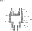
- FIG. 3 is a schematic vertical cross-sectional view of the refrigerant distributor 1. A configuration of the refrigerant distributor 1 will be explained, with reference to FIG. 3 .
- the refrigerant distributor 1 comprises an inflow section 5 made of aluminum and a distributing section 3 made of aluminum.
- the inflow section 5 is structured with an annular section 5a having a circular shape and a tubular section 5b having a diameter smaller than that of the annular section 5a and being coaxially arranged with the central axis of the annular section 5a.
- the refrigerant enters the inflow section 5 from the refrigerant pipe 4 serving as an inflow pipe.
- the distributing section 3 includes a main body section 3a having a tubular shape and being connected to the inflow section 5 and a plurality of outflow sections 3b each having a pipe-like shape and being provided to protrude from the main body section 3a.
- the distributing section 3 is integrally formed in such a manner that the plurality of outflow sections 3b are included in the main body section 3a.
- the distributing section 3 is configured to distribute the refrigerant that entered the distributing section 3 to the plurality of outflow pipes 2.
- FIG. 3 illustrates gaps between the inflow section 5 and the refrigerant pipe 4, between the inflow section 5 and the distributing section 3, and between the outflow sections 3b and the outflow pipes 2 for the purpose of making it easy to understand the structure in view of filling of brazing materials.
- the distributing section 3 is provided with a guide section 3d protruding in an annular shape in the direction to diametrically inside, to fix the positions of insertion ends of the outflow pipes 2 at a basal end of the outflow sections 3b.
- the guide section 3d has an opening diameter smaller than the diameter of each of the outflow sections 3b.
- the lower ends of the outflow pipes 2 arc connected to the outflow sections 3b by being fitted from the inside thereof. Accordingly, when the outflow pipes 2 are fitted into the outflow sections 3b, the outflow pipes 2 are inserted into the outflow sections 3b, and the positions thereof are determined by causing the insertion ends of the outflow pipes 2 to abut against the guide section 3d.
- the width of the guide section 3d is desirable to arrange the width of the guide section 3d to be equal to or smaller than the thickness of each of the outflow pipes 2, in order not to impede the flow of the refrigerant.
- the outer circumference of the annular section 5a of the inflow section 5 is fitted to a cut-out section 3c having a circular shape with a diameter larger than other portions to form a step and being formed on the circumferential surface at the lower end of the main body section 3a.
- the outer circumference of the tube-shaped refrigerant pipe 4 is fitted to a cut-out section 5c having a circular shape with a diameter larger than other portions to form a step and being formed on the inner circumferential surface at the lower end of the tubular section 5b of the inflow section 5.
- the distributing section 3 and the inflow section 5 are joined together by a brazing process. Further, the refrigerant pipe 4 and the inflow section 5 are brazed together, and also, the outflow pipes 2 and the outflow sections 3b are joined together by a brazing process.
- brazing methods include a burner brazing method and a furnace brazing method.
- the burner brazing method is a joining method in which a brazing material is placed at a joined part by applying fluoride flux to the joined part, then the temperature of the brazing material is raised to the melting point of 590 °C by using a burner, to perform a joining process by melting the brazing material.
- the gas burner may use city gas, propane gas, mixed gas of acetylene and oxygen, or other types of gas.
- the furnace brazing method is commonly called NOCOLOK brazing method and is a joining method in which, while using fluoride-based flux similarly to the burner brazing method, a brazing process is performed by introducing nitrogen gas into a furnace and controlling the temperature inside the furnace with a heater.
- Another furnace brazing method besides the NOCOLOK brazing method is a joining method called vacuum brazing method.
- the vacuum brazing method is a joining method by which a brazing process is performed while preventing reoxidation by keeping the inside of a furnace in a high vacuum state so that no oxygen is supplied thereto.
- the NOCOLOK brazing method and the vacuum brazing method are brazing methods having high reliability because it is possible to perform the brazing processes while managing the temperature within the furnace.
- An anti-corrosion treatment is applied to the surface of the refrigerant distributor 1 manufactured with the configuration as described above.
- aluminum is originally an active metal, aluminum immediately reacts with oxygen in the environment to form an oxide film that provides protectivity on the surface thereof. Consequently, aluminum is considered to be a metal that is stable in dry air at room temperature and is highly corrosion resistant. When aluminum is in an environment to be exposed to the air, "pitting corrosion" may occur and a pit may be formed in which the oxide film formed on the surface is locally destructed.
- a "sacrifice positive electrode method" is adopted as described above by which the form of corrosion is controlled to change the development of corrosion from a local corrosion developing in a direction toward the core material into a comprehensive corrosion developing in a direction toward the surface layer, by forming, on the surface thereof, an aluminum-zinc alloy obtained by adding zinc to an aluminum alloy.
- forming a sacrifice positive electrode layer on the surface of the refrigerant distributor 1 will be explained.
- a brazing process that uses a zinc-containing aluminum-silicon alloy obtained by adding zinc to an aluminum-silicon alloy serving as a brazing material for an aluminum brazing process.
- This material is obtained by adding zinc to the aluminum-silicon alloy serving as a base material and has the characteristic where the melting point is lower than that of the base material.
- the melting point of A4047 alloy (88 wt% aluminum / 12 wt% silicon) that can be used as an aluminum-silicon alloy for a brazing process is 590 °C.
- the melting point of metal zinc to be added is 420 °C.
- the melting point of the zinc-containing aluminum-silicon alloy according to the present case approaches the melting point of the metal zinc in accordance with the addition amount of the metal zinc.
- the zinc-containing aluminum-silicon alloy used for forming the sacrifice positive electrode layer will be referred to as a zinc-containing aluminum-silicon alloy brazing material to be used for the brazing process, but does not necessarily have to be a brazing material.
- the flux has a function of ensuring wettability and fluidity of the brazing material on the surface, by removing an aluminum oxide formed on the surface of the aluminum and preventing an oxide film from being newly formed.
- the flux examples include chlorides and fluorides of alkali metals.
- a fluoride of an alkali metal such as potassium fluoroaluminate, e.g., KAlF 4 or K 3 AlF 6 .
- the flux as explained above is applied to such a region of the refrigerant distributor 1 where the sacrifice positive electrode layer is to be formed, more specifically, where the thickness is small within the refrigerant distributor 1, i.e., on the surface and in the vicinity of the outflow sections 3b.
- the refrigerant distributor 1 having a sacrifice positive electrode layer formed thereon is obtained.
- the region where the sacrifice positive electrode layer is to be formed is simply defined by disposing the zinc-containing aluminum-silicon alloy even when the refrigerant distributor 1 has a complicated shape.
- a material obtained by adding 10 wt% metal zinc to A4047 alloy was used as the zinc-containing aluminum-silicon alloy.
- a fluoride of an alkali metal potassium fluoroaluminate, which is configured with a fluoride of potassium and aluminum, was used.
- a process of brazing the refrigerant distributor 1 and the outflow pipes 2 together were performed at the same time.
- potassium fluoroaluminate was used as flux similarly to the example above, and A4047 alloy was used as a brazing material.
- the refrigerant distributor 1 and the outflow pipes 2 are brazed together by burner brazing (to braze the refrigerant distributor 1 and the outflow pipes 2 together by using the aluminum-silicon alloy brazing material), and, simultaneously therewith, the sacrifice positive electrode layer is formed (by disposing the zinc-containing aluminum-silicon alloy brazing material on the surface of the refrigerant distributor 1).
- the zinc-containing aluminum-silicon alloy is melted first, and then the aluminum-silicon alloy is melted subsequently, due to the difference in the melting point between the brazing materials.
- the brazing step in the present example also serves as a forming step of forming the sacrifice positive electrode layer.
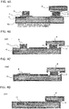
- FIG. 4A is a schematic drawing that illustrates steps from the time when the flux is applied to the time when the aluminum-silicon alloy is melted, together with a manner in which the sacrifice positive electrode layer 11 diffuses, the steps being performed on the refrigerant distributor 1.
- FIG. 4B is another schematic drawing that illustrates the steps from the time when the flux is applied to the time when the aluminum-silicon alloy is melted, together with the manner in which the sacrifice positive electrode layer 11 diffuses, the steps being performed on the refrigerant distributor 1.
- FIG. 4C is yet another schematic drawing that illustrates the steps from the time when the flux is applied to the time when the aluminum-silicon alloy is melted, together with the manner in which the sacrifice positive electrode layer 11 diffuses, the steps being performed on the refrigerant distributor 1.
- FIG. 4D is yet another schematic drawing that illustrates the steps from the time when the flux is applied to the time when the aluminum-silicon alloy is melted, together with the manner in which the sacrifice positive electrode layer 11 diffuses, the steps being performed on the refrigerant distributor 1.
- FIGS. 4A to 4D schematically illustrate the steps from the time when the flux is applied to the time when the aluminum-silicon alloy is melted (the end point of the brazing process), together with the manner in which the sacrifice positive electrode layer diffuses.
- flux 7 is applied to a region 10 where the sacrifice positive electrode layer 11 is to be formed, and a zinc-containing aluminum-silicon alloy brazing material 8 is disposed in the vicinity thereof. Also, flux 7 is applied to locations where aluminum materials 6 are brazed with each other, and an aluminum-silicon alloy brazing material 9 is disposed in the vicinity thereof (step A1).
- the oxide film 6a formed on the surface of the aluminum material is removed, so that the aluminum material 6 can come into contact with the zinc-containing aluminum-silicon alloy brazing material 8 and so that the aluminum material 6 can come into contact with the aluminum-silicon alloy brazing material 9 (step A2).
- step A3 when a heating process is performed in an inert gas atmosphere of nitrogen or other types of gas, while the materials are able to come into contact with each other, the zinc-containing aluminum-silicon alloy brazing material 8 is melted and alloyed with the aluminum material 6 (step A3).
- the aluminum-silicon alloy brazing material 9 having a melting point higher than that of the zinc-containing aluminum-silicon alloy brazing material is subsequently melted and alloyed with the aluminum material 6, and as a result, the aluminum materials 6 are brazed with each other.
- the zinc-containing aluminum-silicon alloy brazing material 8 was melted and alloyed with the aluminum material 6 previously, it is possible to form the sacrifice positive electrode layer 11 because the alloyed zinc diffuses toward the aluminum material 6 side having a lower concentration level of zinc (step A4).
- the brazing process is ended at this point in time.
- the refrigerant distributor 1 having the sacrifice positive electrode layer formed thereon was manufactured.
- a component analysis was performed by using an Electron Probe Micro Analyzer (EPMA) on a cross-sectional plane obtained by cutting out a brazed sample. The analysis was performed in two locations, namely, in the vicinity of the surface of the outflow sections 3b of the distributing section 3 where the sacrifice positive electrode layer 11 had been formed and the joined parts between the refrigerant distributor 1 and the outflow pipes 2.
- EPMA Electron Probe Micro Analyzer
- the brazing material was properly disposed between the refrigerant distributor 1 and the outflow pipes 2 so that the base material and the brazing material were alloyed by the brazing process without any problem.
- the zinc element among others, it was observed that, in a large part of the alloy layer including zinc, aluminum, and silicon, the zinc was uniformly distributed while having a concentration of zinc of 7 wt% to 8 wt%. In the eroded part of the outflow sections 3b, it was learned that the concentration of zinc was gradually getting lower toward the interior thereof.
- the zinc-aluminum-silicon alloy layer having the zinc concentration of 7 wt% to 8 wt% is corroded at first preferentially, and after the layer has disappeared, the zinc-aluminum-silicon alloy layer (the eroded part) having the thickness of 10 ⁇ m to 20 ⁇ m is sequentially corroded from the outer layer thereof toward the part having the lower concentration. It is expected that the development of the corrosion described above inhibits development of corrosion in the outflow sections 3b serving as a core material and in a core material part of the refrigerant distributor 1.
- the function of the layer i.e., anti-corrosion characteristics of the layer.
- a corrosion test was performed on the manufactured refrigerant distributor 1 having the sacrifice positive electrode layer formed thereon, to verify that the anti-corrosion characteristics were ensured by evaluating the status of corrosion. The following describes details of the corrosion test that was performed and results of the test (the status of corrosion).
- the refrigerant distributor 1 is applied to the outdoor unit or another element of the air-conditioning apparatus 200. It is therefore considered to be reasonable to assume, as for a cause of corrosion, that aluminum may be corroded by salt damage.
- a combined cycle test was performed by simulating corrosion caused by salt damage and by using salt water as a corrosion fluid to realize an acceleration test, to evaluate the status of corrosion.
- the combined cycle test was performed for 1,000 hours by using a 5-wt% NaCl water solution as a liquid to be sprayed onto the refrigerant distributor 1 having the sacrifice positive electrode layer formed thereon according to the present case, to evaluate the status of corrosion.
- a component analysis using EPMA was performed by embedding a corrosion sample in resin and observing a cut cross-sectional plane with the use of a metal microscope.
- the aluminum core material layer it was confirmed that an oxide having a small thickness (on the order of submicrometer) was formed on the surface layer. From these results, it was confirmed that corrosion of the aluminum core material layer was inhibited by the corrosion developing in the sacrifice positive electrode layer 11 formed by the brazing process.
- the sacrifice positive electrode layer 11 is formed on the surface by using the zinc-containing aluminum-silicon alloy brazing material 8. As a result, it is possible to form the sacrifice positive electrode layer 11 conveniently, efficiently, and accurately, on the surface of the refrigerant distributor 1 having a complicated shape. Further, it is possible to prevent the strength in the surroundings of the joined parts from being lowered by excessive heating during the formation of the sacrifice positive electrode layer 11.
- the sacrifice positive electrode layer 11 is formed by applying the brazing-purpose flux 7 to the region on the surface of the refrigerant distributor 1 where the sacrifice positive electrode layer 11 is to be formed, disposing the zinc-containing aluminum-silicon alloy brazing material 8 in the vicinity of the flux-applied region, and performing the heating process on the zinc-containing aluminum-silicon alloy brazing material 8 and the surface of the refrigerant distributor 1.
- the brazing process is performed by using the aluminum-silicon alloy brazing material 9, to form the aluminum-silicon alloy brazing material section.
- the melting point of the zinc-containing aluminum-silicon alloy brazing material 8 forming the sacrifice positive electrode layer 11 is lower than the melting point of the aluminum-silicon alloy brazing material 9.
- the sacrifice positive electrode layer 11 by melting only the zinc-containing aluminum-silicon alloy brazing material 8. Consequently, it is possible to prevent the occurrence of re-melting, erosion, and other phenomena in the surroundings of the joined part between the refrigerant pipe 4 and the refrigerant distributor 1 and the joined part between the outflow pipes 2 and the refrigerant distributor 1, during the formation of the sacrifice positive electrode layer 11.
- the sacrifice positive electrode layer 11 is also formed on the surface of the refrigerant distributor 1.
- the sacrifice positive electrode layer 11 may be formed on the surface of the refrigerant distributor 1 in which, due to constraints in the manufacturing process, the outflow pipes 2 and the outflow sections 3b have already been joined together in advance by forming an aluminum-silicon alloy brazing material section through a brazing process.
- a manufacturing procedure is specified to include a step of forming the sacrifice positive electrode layer 11 subsequent to a step of brazing and joining the refrigerant distributor 1 with the pipes.
- a refrigerant distributor 1 is prepared that is already joined with the outflow pipes 2 by forming an aluminum-silicon alloy brazing material section through a brazing process.
- the flux 7 is applied to the outflow sections 3b of the refrigerant distributor 1 prepared in this manner, and the zinc-containing aluminum-silicon alloy brazing material 8 is disposed.
- the flux 7 and the zinc-containing aluminum-silicon alloy brazing material 8 are the same materials and have the same positional arrangements as those in Case 1.
- a heating process was performed on these by a burner brazing, and the heating process was completed at the point in time when the zinc-containing aluminum-silicon alloy brazing material 8 was melted.
- the heating process was performed up to a temperature at which the aluminum-silicon alloy brazing material 9 was not melted, but only the zinc-containing aluminum-silicon alloy brazing material 8 was melted.
- the sacrifice positive electrode layer 11 is formed by using the zinc-containing aluminum-silicon alloy brazing material 8 on the surface of the refrigerant distributor 1 in which the brazing processes have already been performed to join the refrigerant pipe 4 with the inflow section 5 and to join the outflow pipes 2 with the outflow sections 3b.
- the order of the manufacturing procedure in the surroundings of the joined parts is defined so that the sacrifice positive electrode layer 11 is formed after the joining process on the joined parts is performed.
- the sacrifice positive electrode layer 11 is formed by performing the heating process up to a temperature at which the aluminum-silicon alloy brazing material 9 is not melted, but only the zinc-containing aluminum-silicon alloy brazing material 8 is melted. For this reason, it is possible to inhibit the occurrence of re-melting, erosion, and other phenomena in the surroundings of the brazed joined parts. Consequently, it is possible to inhibit the occurrence of re-melting, erosion, and other phenomena, and it is also possible to avoid destruction that may be started in the strength-lowered parts, because the lowering of the strength is prevented.
- the addition amount of the zinc As for the addition amount of the zinc, the larger the addition amount is, the lower becomes the melting point, and the easier it is to inhibit the excessive heating. However, at the same time, when the content amount of the zinc is larger, the corrosion speed of the material itself increases, i.e., the material is corroded more easily. It is therefore necessary to control the addition amount of the zinc to be in an optimal range. In the present example, to find the optimal range, impacts of the addition amount of the zinc that are made on thermodynamic characteristics and corrosion resistance of the zinc-containing aluminum-silicon alloy according to the present case were studied.
- A4047 containing 12 wt% silicon was prepared.
- Zinc-containing aluminum-silicon alloys were produced while using the concentration of the metal zinc to be added to A4047 alloy as a parameter.
- FIG. 5 is a chart illustrating dependence on concentration of zinc with respect to melting points of the zinc-containing aluminum-silicon alloy according to Case 3 of the present invention.
- the melting point of the zinc-containing aluminum-silicon alloy decreased from 580 °C, which is the melting point of the aluminum-silicon alloy serving as the base material, toward 420 °C, which is the melting point of metal zinc, as the concentration of the zinc increased. It was also learned that the decreasing ratio became more gradual as the concentration of the zinc increased. Further, it was observed that, when the concentration of the zinc was lower than 5 wt%, there was hardly any difference (equal to or smaller than 20 °C) between the melting point of the zinc-containing aluminum-silicon alloy and the melting point of the aluminum alloy.
- the melting point of the zinc-containing aluminum-silicon alloy forming the sacrifice positive electrode layer 11 is necessary to be lower than the melting point of the aluminum-silicon alloy positioned in the surroundings of the joined parts. In other words, it was observed that it is necessary to keep the concentration of the zinc in the alloy at a predetermined level.
- the zinc contained in the zinc-containing aluminum-silicon alloy has a function of weakening an oxide film formed on the surface of the aluminum alloy, the larger the addition amount of the zinc is, the higher is the speed of the corrosion.
- impacts on the speed of corrosion made by the concentration of the zinc in the zinc-containing aluminum-silicon alloy were evaluated by performing an electrochemical measuring process. It is possible to derive a corrosion electric current by performing an oxidation/reduction current measuring process on an evaluated material and to convert the corrosion current into a corrosion speed.
- FIG. 6 is a chart illustrating dependence on concentration of zinc with respect to corrosion speeds of the zinc-containing aluminum-silicon alloy according to Case 3 of the present invention.
- the concentration of the zinc is in the range from 5 wt% to 15 wt % inclusive of the zinc-containing aluminum-silicon alloy.
- concentration of the zinc contained in the zinc-containing aluminum-silicon alloy brazing material 8 is 5 wt% or higher, it is possible to have a temperature difference during the heating process because the melting point of the zinc-containing aluminum-silicon alloy brazing material 8 is certainly lower than the melting point of the aluminum-silicon alloy brazing material 9.
- the concentration of the zinc in the zinc-containing aluminum-silicon alloy brazing material 8 is 15 wt% or lower, it is possible to ensure the corrosion resistance because the corrosion speed does not exceed the tolerance range of 1 ⁇ g/h ⁇ cm 2 .
- the concentration of the zinc in the zinc-containing aluminum-silicon alloy brazing material 8 is limited to the optimal range, it is possible to form the sacrifice positive electrode layer 11 by performing the heating process on the zinc-containing aluminum-silicon alloy brazing material 8 after the joining process is performed while using the aluminum-silicon alloy brazing material 9. Consequently, it is possible to inhibit the occurrence of re-melting, erosion, and other phenomena in the surroundings of the joined parts and to also ensure the corrosion resistance of the refrigerant distributor 1.
- a refrigerant distributor manufacturing apparatus 300 and a manufacturing method for manufacturing the refrigerant distributor 1 by using the same will be explained, the refrigerant distributor manufacturing apparatus 300 being configured to join the inflow section 5 of the distributing section 3 with the refrigerant pipe 4 serving as an inflow pipe and, either at the same time as or subsequent to the joining of the outflow sections 3b with the outflow pipes 2, configured to form the sacrifice positive electrode layer 11 in the vicinity of the outflow sections 3b, which is where the thickness is smallest within the distributing section 3, i.e., where the corrosion resistance should be ensured.
- FIG. 7 is a drawing that illustrates the refrigerant distributor manufacturing apparatus 300 used for forming the sacrifice positive electrode layer 11 on the surface of the refrigerant distributor 1 according to Example 1.
- the refrigerant distributor manufacturing apparatus 300 includes: an applying unit 61 to perform an applying process; an alloy disposing unit 62 to dispose the zinc-containing aluminum-silicon alloy brazing material 8; an inserting unit 63 to insert the outflow pipes 2 into the outflow sections 3b of the refrigerant distributor 1; a brazing material disposing unit 64 to dispose the aluminum-silicon alloy brazing material 9; and a heating unit 65 that is configured to form the sacrifice positive electrode layer 11 for the refrigerant distributor 1, that includes a heating member, and is configured to braze the outflow pipes 2 with the outflow sections 3b of the refrigerant distributor 1.
- the applying unit 61, the alloy disposing unit 62, the inserting unit 63, the brazing material disposing unit 64, and the heating unit 65 are connected together by a line 66.
- the line 66 makes it possible for the other constituent members of the refrigerant distributor 1 to travel between these units.
- an aluminum-manganese based alloy, A3003 is used as the aluminum material for the distributing section 3, the refrigerant pipe 4 serving as an inflow pipe, and the outflow pipes 2.
- the aluminum material that can be used include A1000-series alloys (A1050, A1070, and so on) containing pure aluminum; A5000-series alloys (A5052 and so on) which are aluminum-magnesium alloys; and A6000-series alloys (A6063 and so on) which are aluminum-magnesium-silicon alloys.
- the applying unit 61 filled with the flux 7 serving as a solvent applies the flux 7 to the surface of the distributing section 3 and the outflow sections 3b of the refrigerant distributor 1.
- the alloy disposing unit 62 disposes the zinc-containing aluminum-silicon alloy brazing material 8 at the basal end of the outflow sections 3b of the refrigerant distributor 1 to which the flux 7 has been applied.
- the method for disposing the zinc-containing aluminum-silicon alloy brazing material 8 it is necessary to design the procedure so that the sacrifice positive electrode layer 11 is formed on the surface of the outflow sections 3b and the distributing section 3. The details will be explained below.
- the heating unit 65 of the refrigerant distributor manufacturing apparatus 300 heats the refrigerant distributor 1 to which the flux 7 has been applied and for which the zinc-containing aluminum-silicon alloy brazing material 8 has been disposed.
- the sacrifice positive electrode layer 11 is formed on the surface of the outflow sections 3b and the distributing section 3 of the refrigerant distributor 1.
- the applying unit 61 filled with the flux 7 serving as a solvent similarly applies the flux 7 to the surface corresponding to a fitted part where the outflow sections 3b of the refrigerant distributor 1 and the outflow pipes 2 are fitted together.
- the inserting unit 63 fits the outflow sections 3b of the refrigerant distributor 1 and the outflow pipes 2 together to which the flux 7 has been applied on the surface thereof.
- the brazing material disposing unit 56 disposes the aluminum-silicon alloy brazing material 9 at the fitted part between the outflow pipes 2 and the outflow sections 3b of the refrigerant distributor 1.
- the outflow pipes 2 and the outflow sections 3b of the refrigerant distributor 1 are brazed together, as a result of a heating process by the heating unit 65 included in the refrigerant distributor manufacturing apparatus 300 that is performed, while employing the heating member, on the refrigerant distributor 1 to which the flux 7 has been applied and for which the aluminum-silicon alloy brazing material 9 has been disposed.
- the melting point of the zinc-containing aluminum-silicon alloy brazing material 8 is lower than that of the aluminum-silicon alloy brazing material 9. Accordingly, the zinc component diffuses as the sacrifice positive electrode layer 11 in the direction toward the core material of the refrigerant distributor 1 at a temperature lower than the temperature used for the brazing process. Consequently, it is preferable to perform the step of forming the sacrifice positive electrode layer 11 either at the same time as or after the brazing step.
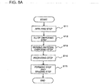
- FIG. 8A is a flowchart illustrating a method for manufacturing the refrigerant distributor 1 to form the sacrifice positive electrode layer 11 on the surface of the refrigerant distributor 1.
- FIG. 8B is a flowchart illustrating another method for manufacturing the refrigerant distributor 1 to form the sacrifice positive electrode layer 11 on the surface of the refrigerant distributor 1.
- the refrigerant distributor manufacturing apparatus 300 applies the flux 7 to the surface corresponding to the fitted part of the outflow sections 3b of the refrigerant distributor 1 and the outflow pipes 2, by employing the applying unit 61 filled with the flux 7 serving as a solvent. Further, the refrigerant distributor manufacturing apparatus 300 applies the flux 7 to the surface of the distributing section 3 and the outflow sections 3b of the refrigerant distributor 1.
- the refrigerant distributor manufacturing apparatus 300 disposes, by employing the alloy disposing unit 62, the zinc-containing aluminum-silicon alloy brazing material 8 at the basal end of the outflow sections 3b of the refrigerant distributor 1 to which the flux 7 has been applied.
- a brazing material disposing step in step S13 by employing the inserting unit 63, the refrigerant distributor manufacturing apparatus 300 fits together the outflow sections 3b of the refrigerant distributor 1 and the outflow pipes 2 to which the flux 7 has been applied on the surface thereof. Further, by employing the brazing material disposing unit 56, the refrigerant distributor manufacturing apparatus 300 disposes the aluminum-silicon alloy brazing material 9 at the fitted part between the outflow pipes 2 and the outflow sections 3b of the refrigerant distributor 1.
- the refrigerant distributor manufacturing apparatus 300 prepares the heating unit 65 configured to heat the zinc-containing aluminum-silicon alloy brazing material 8 and the aluminum-silicon alloy brazing material 9, so that a burner brazer serving as the heating member is able to perform a heating process.
- the refrigerant distributor manufacturing apparatus 300 performs a brazing process on the outflow pipes 2 and the outflow sections 3b of the refrigerant distributor 1, as a result of a heating process realized by the heating unit 65 through a heating process of the burner brazer serving as the heating member, performed on the refrigerant distributor 1 to which the flux 7 has been applied and for which the aluminum-silicon alloy brazing material 9 has been disposed.
- the refrigerant distributor manufacturing apparatus 300 forms the sacrifice positive electrode layer 11 on the surface of the outflow sections 3b and the distributing section 3 of the refrigerant distributor 1, as a result of a heating process realized by the heating unit 65 through a heating process of the burner brazer serving as the heating member, performed on the refrigerant distributor 1 to which the flux 7 has been applied and for which the zinc-containing aluminum-silicon alloy brazing material 8 has been disposed.
- the zinc-containing aluminum-silicon alloy brazing material 8 is melted first to be alloyed with the aluminum material 6. After that, the heating process is continued to raise the heating temperature so that the aluminum-silicon alloy brazing material 9 is melted and alloyed with the aluminum material 6.
- the refrigerant distributor manufacturing apparatus 300 applies the flux 7 to the surface corresponding to the fitted part of the outflow sections 3b of the refrigerant distributor 1 and the outflow pipes 2, by employing the applying unit 61 filled with the flux 7 serving as a solvent.
- a brazing material disposing step in step S22 by employing the inserting unit 63, the refrigerant distributor manufacturing apparatus 300 fits together the outflow sections 3b of the refrigerant distributor 1 and the outflow pipes 2 to which the flux 7 has been applied on the surface thereof. Also, by employing the brazing material disposing unit 56, the refrigerant distributor manufacturing apparatus 300 disposes the aluminum-silicon alloy brazing material 9 at the fitted part between the outflow pipes 2 and the outflow sections 3b of the refrigerant distributor 1.
- the refrigerant distributor manufacturing apparatus 300 performs a brazing process on the outflow pipes 2 and the outflow sections 3b of the refrigerant distributor 1, as a result of a heating process realized by the heating unit 65 through a heating process of the burner brazer serving as the heating member, performed on the refrigerant distributor 1 to which the flux 7 has been applied and for which the aluminum-silicon alloy brazing material 9 has been disposed.
- the refrigerant distributor manufacturing apparatus 300 applies the flux 7 to the surface of the distributing section 3 and the outflow sections 3b of the refrigerant distributor 1, by employing the applying unit 61 filled with the flux 7 serving as a solvent.
- the refrigerant distributor manufacturing apparatus 300 disposes the zinc-containing aluminum-silicon alloy brazing material 8 at the basal end of the outflow sections 3b of the refrigerant distributor 1 to which the flux 7 has been applied.
- the refrigerant distributor manufacturing apparatus 300 forms the sacrifice positive electrode layer 11 on the surface of the outflow sections 3b and the distributing section 3 of the refrigerant distributor 1, as a result of a heating process realized by the heating unit 65 through a heating process of the burner brazer serving as the heating member, performed on the refrigerant distributor 1 to which the flux 7 has been applied and for which the zinc-containing aluminum-silicon alloy brazing material 8 has been disposed.
- the heating temperature is lower than that in the brazing step in step S23, as explained in Case 2.
- the heating process is performed up to a temperature at which the aluminum-silicon alloy brazing material 9 is not melted, but only the zinc-containing aluminum-silicon alloy brazing material 8 is melted.
- the inner and outer circumferences of the outflow sections 3b of the refrigerant distributor 1 are selected as the locations in which the zinc-containing aluminum-silicon alloy brazing material 8 is disposed.
- it is also effective to carry out another concept regarding disposing methods.
- an effective method for disposing the zinc-containing aluminum-silicon alloy brazing material 8 to form the sacrifice positive electrode layer 11 will be explained.
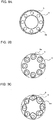
- FIG. 9A is a drawing illustrating a method of disposing the zinc-containing aluminum-silicon alloy brazing material 8 to form the sacrifice positive electrode layer 11 on the surface of the refrigerant distributor 1.
- FIG. 9B is a drawing illustrating another method for disposing the zinc-containing aluminum-silicon alloy brazing material 8 to form the sacrifice positive electrode layer 11 on the surface of the refrigerant distributor 1.
- FIG. 9C is a drawing illustrating yet another method for disposing the zinc-containing aluminum-silicon alloy brazing material 8 to form the sacrifice positive electrode layer 11 on the surface of the refrigerant distributor 1.
- the refrigerant distributor 1 is projected from the side of the outflow sections 3b.
- the material is disposed on the inside and the outside of the plurality of outflow sections 3b of the refrigerant distributor 1 in circular formations.
- the material is disposed at the basal end of each of the outflow sections 3b of the refrigerant distributor 1 in circular formations or horseshoe formations (not illustrated). With this arrangement also, it is possible to achieve the same advantageous effect as that of the example in FIG. 9A .
- the refrigerant distributor 1 having a sacrifice positive electrode layer formed thereon and being manufactured by the refrigerant distributor manufacturing apparatus 300 was inspected, it was observed that the sacrifice positive electrode layer 11 was formed in an excellent manner on the surface of the outflow sections 3b and the distributing section 3 while uniformly diffusing in the surface layer direction and the depth direction.
- the flux 7 to remove the aluminum oxide from the surface thereof is applied in advance, for the purpose of melting the zinc-containing aluminum-silicon alloy brazing material 8 or the aluminum-silicon alloy brazing material 9 to be alloyed with the refrigerant distributor 1, the outflow pipes 2, or the plurality of outflow sections 3b.
- This procedure uses the zinc-containing aluminum-silicon alloy brazing material 8 or the aluminum-silicon alloy brazing material 9 to which the flux 7 serving as a solvent is applied in advance on the surface thereof.
- the zinc-containing aluminum-silicon alloy brazing material 8 to which the flux 7 has been applied is disposed by implementing any of the disposing methods described in Example 2. Further, the aluminum-silicon alloy brazing material 9 to which the flux 7 has been applied is disposed in a ring formation at such a part where the plurality of outflow pipes 2 and the plurality of outflow sections 3b are fitted together, respectively.
- a brazing and heating process is performed on the refrigerant distributor 1, the outflow pipes 2, the zinc-containing aluminum-silicon alloy brazing material 8, and the aluminum-silicon alloy brazing material 9 that are combined together in this manner.
- the heating process the zinc-containing aluminum-silicon alloy brazing material 8 is melted first, together with the flux 7. Subsequently, the aluminum-silicon alloy brazing material 8 is melted together with the flux 7.
- the flux 7 removes the aluminum oxide formed on the surface of the refrigerant distributor 1, the outflow pipes 2, and the outflow sections 3b, to ensure wettability and fluidity of the brazing material on the surface.
- the aluminum base material and the aluminum alloy brazing material are alloyed together, so that a sacrifice positive electrode layer forming process and a brazing and joining process are each performed.
- the refrigerant distributor 1 having a sacrifice positive electrode layer formed thereon and being manufactured by the refrigerant distributor manufacturing apparatus 300 according to Example 1 while using these materials and the manufacturing step described above was inspected, it was observed that the sacrifice positive electrode layer 11 was formed in an excellent manner on the surface of the outflow sections 3b and the distributing section 3 while uniformly diffusing in the surface layer direction and the depth direction.
- the refrigerant distributor manufacturing apparatus 300 applies the flux 7 to remove the aluminum oxide, to the surface of the zinc-containing aluminum-silicon alloy brazing material 8 and the aluminum-silicon alloy brazing material 9.
- the sacrifice positive electrode layer 11 is formed by disposing and heating the zinc-containing aluminum-silicon alloy brazing material 8 to which the flux 7 has been applied. Accordingly, there is no need to apply the flux 7 to fit the complicated shapes of the outflow sections 3b. There is no need to apply the aluminum-silicon alloy brazing material 9 to fit the complicated shapes of the outflow sections 3b, either. Consequently, it is possible to form the sacrifice positive electrode layer conveniently, efficiently, and accurately, on the surface of the refrigerant distributor having a complicated shape.
- the sacrifice positive electrode layer and the brazed joined parts are formed in an excellent manner, by manufacturing the refrigerant distributor 1 with the use of the zinc-containing aluminum-silicon alloy brazing material 8 and the aluminum-silicon alloy brazing material 9 arranged in advance to support the flux 7 on the surface thereof.
- the refrigerant distributor 1 including: the inflow section 5 into which the refrigerant enters from the refrigerant pipe 4 serving as an inflow pipe and that is made of aluminum, the plurality of outflow pipes 2 each of which allows the entering refrigerant to flow out and each of which is made of aluminum, and the distributing section 3 that includes the plurality of outflow sections 3b each being connected to a different one of the plurality of outflow pipes 2 and that is made of aluminum.
- the method of manufacturing the refrigerant distributor 1 includes an applying step of applying flux 7 to remove an aluminum oxide to a surface of the plurality of outflow sections 3b and the distributing section 3.
- the method includes an alloy disposing step of disposing the zinc-containing aluminum-silicon alloy brazing material 8 on the surface to which the flux is applied.
- the method includes a forming step of forming the sacrifice positive electrode layer 11 on the surface by heating the disposed zinc-containing aluminum-silicon alloy brazing material 8.
- the method includes a brazing material disposing step of inserting the plurality of outflow pipes 2 into the plurality of outflow sections 3b, respectively, and disposing the aluminum-silicon alloy brazing material 9 on the surface of the outflow sections 3b.
- the method includes a brazing step of brazing the plurality of outflow sections 3b with the plurality of outflow pipes 2, respectively, by heating the disposed aluminum-silicon alloy brazing material 9.
Landscapes
- Engineering & Computer Science (AREA)
- Mechanical Engineering (AREA)
- Physics & Mathematics (AREA)
- Thermal Sciences (AREA)
- General Engineering & Computer Science (AREA)
- Prevention Of Electric Corrosion (AREA)
- Heat-Exchange Devices With Radiators And Conduit Assemblies (AREA)
- Details Of Heat-Exchange And Heat-Transfer (AREA)
Description
- The present invention relates to a methods of manufacturing a refrigerant distributor, see claims 1-2.
- A refrigerant distributor is needed at an inlet of a heat exchanger configured to operate as a condenser or an evaporator of a refrigeration cycle device, in order to separate the refrigerant into multiple paths when such a heat exchanger has a divided, multiple refrigerant paths inside. The refrigeration cycle device may be an air-conditioning apparatus, or a refrigerating device. air-conditioning apparatus.
- Further, for example, for a multi-type air-conditioning apparatus in which a plurality of outdoor units and/or indoor units are connected in parallel, a refrigerant distributor is needed for distributing refrigerant to each of the units from a main refrigerant passage.
- When a heat transfer tube of the heat exchanger is made of aluminum, an aluminum material processed by shaving or other processing is used for a member of a distributing section of the refrigerant distributor. Further, outflow pipes and an inflow pipe connected to the distributing section are also each configured by using an aluminum material. To join the outflow pipes with the distributing section and to join the inflow pipe with the distributing section, a joining process involving a brazing process is commonly used due to complicated shapes of these joined members.
- To perform the brazing process, an aluminum brazing material configured with an alloy of aluminum and silicon is used as a brazing material. Further, the members are joined together by alloying the aluminum brazing material with the outflow pipes, the distributing section, and the inflow pipe each by performing a heating process with the use of a burner or other devices. Accordingly, the outflow pipes, the refrigerant distributor, the inflow pipe, and the brazed parts are all structured with either aluminum metal or an aluminum alloy.
- The refrigerant distributor, the heat exchanger, and the air-conditioning apparatus configured by using aluminum metal are installed in an outdoor environment and are therefore prone to have chloride ions adhered to the surface thereof, the chloride ions being derived from sea salt grains transported in the outside air. The adhesion of the chloride ions locally destructs an aluminum oxide film being formed on the surface of the aluminum and having corrosion resistance. A local corrosion is thus developed starting with the destruction location. When the local corrosion keeps being developed, a through hole may be formed, as a result, through which the refrigerant can leak. Consequently, the devices may reach the end of the product life earlier than expected.
- To inhibit the development of the local corrosion, a method is effective that forms a "sacrifice positive electrode layer" being a material that is electrochemically less noble (more unstable) than aluminum on the surface of the aluminum metal, so that the sacrifice positive electrode layer is corroded first preferentially. To form such a sacrifice positive electrode layer (material) for aluminum, an aluminum-zinc alloy obtained by mixing zinc with aluminum is commonly used.
- Generally-known examples of an aluminum material having a sacrifice positive electrode layer formed thereon obtained by forming such a sacrifice positive electrode layer on the surface of aluminum include "a zinc-sprayed aluminum material", and "an aluminum clad material having a sacrifice positive electrode layer formed thereon", among others.
- The zinc-sprayed aluminum material is obtained by forming an aluminum-zinc alloy by spraying melted metal zinc onto the surface and subsequently performing a heating process to cause the metal zinc on the surface to diffuse to the inside (see
Patent Literature 1, for example). The aluminum clad material having a sacrifice positive electrode layer formed thereon is obtained by putting an aluminum-zinc alloy material together with an aluminum material and further performing a rolling and pressure-welding process thereon at high temperature. Patent Literature 2 (basis for the preamble ofclaims 1 and 2) relates to improving reliability by excellently joining an aluminium distribution part to a plurality of aluminium ex-current canals. This document describes arefrigerant distributor 2 including thealuminium distribution part 6 which distributes a refrigerant flowing from an aluminiumincurrent canal 7 into a plurality of the aluminium ex-current canals. Each ex-current canal is formed of afirst ex-current canal 3 and asecond ex-current canal 4. Eachfirst ex-current canal 3 is joined to thedistribution part 6 by being brazed in furnace, and each firstex-current canal 3 and each secondex-current canal 4 are joined by burner brazing. Thedistributor 6 and the firstex-current canal 3 are brazed in the furnace, thus facilitating temperature control. Thedistribution part 6 and the firstex-current canal 3 can be excellently joined, thus providing the reliable refrigerant distributor. -
- Patent Literature 1: Japanese Unexamined Patent Application Publication
JP 4-015 496 A - Patent Literature 2:
JP 2012013289 - As explained above, to form the sacrifice positive electrode layer that is effective in inhibiting the local corrosion of aluminum refrigerant pipes in heat exchangers, pipes that have conventionally been used include a "zinc-sprayed aluminum pipe" which is obtained by thermally spraying zinc on a circular aluminum pipe or on a flat-shaped heat transfer tube (which hereinafter will be referred to as "flat tube") of which the cross-sectional shape is flat and which has a flat section in the outline thereof and has a plurality of refrigerant passages on the inside thereof. Another conventional example is "a circular aluminum clad pipe having a sacrifice positive electrode layer formed thereon" obtained by cladding together a circular aluminum-zinc alloy pipe with a circular aluminum pipe.
- Further, the abovementioned refrigerant distributor is formed to have a complicated shape having a plurality of branches, instead of a simple shape such as a uniform circular or rectangular column, because the plurality of outflow pipes and the distributing section are brazed and joined together, and also, the inflow pipe and the distributing section are brazed and joined together. Due to the complicated shape of the aluminum refrigerant distributor, it is considered difficult to form, as the sacrifice positive electrode layer on the surface of the aluminum refrigerant distributor, an aluminum clad material having the sacrifice positive electrode layer formed thereon by putting an aluminum-zinc alloy and an aluminum alloy together in advance.
- Consequently, to form the sacrifice positive electrode layer on the refrigerant distributor having a complicated shape, it is necessary to thermally spray zinc onto the shaped refrigerant distributor so that the zinc diffuses on the surface. In that situation, to thermally spray the zinc onto an arbitrary region of the refrigerant distributor and cause the zinc to diffuse toward the inside of the core material, it is necessary to install a nozzle capable of spraying melted zinc onto a desired region. To form a zinc-sprayed region on a refrigerant distributor having a plurality of branches, the number of installed nozzles and the method for arranging the nozzles with respect to the refrigerant distributor become more complicated, as the number of zinc-sprayed regions increases, which makes it difficult to form the sacrifice positive electrode layer.
- Further, when a pipe is joined with the refrigerant distributor, a brazing material is placed between the pipe and the refrigerant distributor, to perform a brazing process by applying heat up to a temperature close to 600 °C. When heating process is excessive during the heating process, a phenomenon called "erosion" occurs, where the melted brazing material erodes toward the inside of the core material, and the strength of the core material is thus lowered. When such erosion has occurred in a brazed part, the strength thereof is lowered during the manufacture of the refrigerant distributor, which may further lead to destruction starting in the strength-lowered part.
- To overcome the problems described above, it is an object of the present invention to provide a refrigerant distributor manufacturing method by which and with which it is possible to form a sacrifice positive electrode layer conveniently, efficiently, and accurately, on the surface of the refrigerant distributor having a complicated shape.
- Further, it is an object of the present invention to provide a method for manufacturing a refrigerant distributor by which and with which it is possible to inhibit the strength in the surroundings of joined parts from being lowered by excessive heating during the formation of the sacrifice positive electrode layer.
- A refrigerant distributor manufacturing method according to the present invention is given in
claim 1 and is a method of manufacturing a refrigerant distributor, the refrigerant distributor including an inflow section made of aluminum, into which refrigerant enters from an inflow pipe, a plurality of outflow pipes each of which is made of aluminum and each of which allows the entering refrigerant to flow out therethrough, and a distributing section made of aluminum, the distributing section including a plurality of outflow sections each being connected to one of the plurality of outflow pipes, the method comprising: an applying step of applying flux that removes aluminum oxide to a surface of the plurality of outflow sections and the distributing section; an alloy disposing step of disposing a zinc-containing aluminum-silicon alloy on the surface to which the flux is applied; a forming step of forming a sacrifice positive electrode layer on the surface by heating the disposed zinc-containing aluminum-silicon alloy; a brazing material disposing step of inserting the plurality of outflow pipes into the plurality of outflow sections, respectively, and disposing aluminum-silicon alloy brazing material on the surface of the outflow sections; and a brazing step of brazing the plurality of outflow sections with the plurality of outflow pipes, respectively, by heating the disposed aluminum-silicon alloy brazing material. - A further method of manufacturing a refrigerant distributor according to the present invention is defined in
claim 2. - Further embodiments of the present invention are defined in the dependent claims.
- By using the refrigerant distributor manufacturing method it is possible to form the sacrifice positive electrode layer conveniently, efficiently, and accurately on the surface of the refrigerant distributor having a complicated shape. Further, it is also possible to prevent the strength in the surroundings of the joined parts from being lowered by excessive heating during the formation of the sacrifice positive electrode layer.
-
- FIG. 1
- is a refrigerant circuit diagram illustrating a schematic configuration of an air-conditioning apparatus.
- FIG. 2
- is a schematic drawing illustrating a connection state of a refrigerant distributor and a heat exchanger.
- FIG. 3
- is a schematic vertical cross-sectional view of the refrigerant distributor.
- FIG. 4A
- is a schematic drawing that illustrates steps from the time when flux is applied to the time when an aluminum-silicon alloy is melted, together with a manner in which a sacrifice positive electrode layer diffuses, the steps being performed on the refrigerant distributor.
- FIG. 4B
- is another schematic drawing that illustrates the steps from the time when the flux is applied to the time when the aluminum-silicon alloy is melted, together with the manner in which the sacrifice positive electrode layer diffuses, the steps being performed on the refrigerant distributor.
- FIG. 4C
- is yet another schematic drawing that illustrates the steps from the time when the flux is applied to the time when the aluminum-silicon alloy is melted, together with the manner in which the sacrifice positive electrode layer diffuses, the steps being performed on the refrigerant distributor.
- FIG. 4D
- is yet another schematic drawing that illustrates the steps from the time when the flux is applied to the time when the aluminum-silicon alloy is melted, together with the manner in which the sacrifice positive electrode layer diffuses, the steps being performed on the refrigerant distributor.
- FIG. 5
- is a chart illustrating dependence on concentration of zinc with respect to melting points of a zinc-containing aluminum-silicon alloy.
- FIG. 6
- is a chart illustrating dependence on concentration of zinc with respect to corrosion speeds of the zinc-containing aluminum-silicon alloy.
- FIG. 7
- is a drawing that illustrates a refrigerant distributor manufacturing apparatus used for forming a sacrifice positive electrode layer on a surface of a refrigerant distributor.
- FIG. 8A
- is a flowchart illustrating a method for manufacturing a refrigerant distributor to form a sacrifice positive electrode layer on a surface of a refrigerant distributor.
- FIG. 8B
- is a flowchart illustrating another method for manufacturing a refrigerant distributor to form a sacrifice positive electrode layer on a surface of a refrigerant distributor.
- FIG. 9A
- is a drawing illustrating a method for disposing a zinc-containing aluminum-silicon alloy to form a sacrifice positive electrode layer on a surface of a refrigerant distributor.
- FIG. 9B
- is a drawing illustrating another method for disposing the zinc-containing aluminum-silicon alloy to form the sacrifice positive electrode layer on the surface of the refrigerant distributor.
- FIG. 9C
- is a drawing illustrating yet another method for disposing the zinc-containing aluminum-silicon alloy to form the sacrifice positive electrode layer on the surface of the refrigerant distributor.
- Embodiments of the present invention will be described hereinafter. The modes illustrated in the drawings are merely examples and are not intended to limit the present invention. Further, some reference signs among the drawings indicate same or equivalent elements, which applies throughout the description of the present disclosure. Further, the dimensional relationships among the constituent elements illustrated in the drawings may differ from those in actual ones.
-
FIG. 1 is a refrigerant circuit diagram illustrating a schematic configuration of an air-conditioning apparatus 200. As illustrated inFIG. 1 , the air-conditioning apparatus 200 includes a refrigerant circuit structured by connecting the following together with a refrigerant pipe 4: acompressor 201, amuffler 202, a four-way valve 203, anoutdoor heat exchanger 100, acapillary pipe 205, astrainer 206, anelectronic expansion valve 207,stop valves indoor heat exchanger 209, and anauxiliary muffler 210. - An indoor unit that is for the air-
conditioning apparatus 200 and that includes theindoor heat exchanger 209 is provided with acontroller 211 configured to control actuators or the like of thecompressor 201, theelectronic expansion valve 207, and so on, based on temperatures of the outside air, the inside of the room, the refrigerant, and other factors. The four-way valve 203 is a valve configured to switch between refrigeration cycles of cooling and heating and is controlled by thecontroller 211. - Next, an example of an operation performed by the air-
conditioning apparatus 200 during a cooling operation will be explained, with reference toFIG. 1 . When the four-way valve 203 is switched to the cooling operation by thecontroller 211, the refrigerant is compressed by thecompressor 201 to become gas refrigerant having high temperature and high pressure and to flow into theoutdoor heat exchanger 100 via the four-way valve 203. The gas refrigerant having the high temperature and the high pressure and having flowed into theoutdoor heat exchanger 100 exchanges heat with (transfers heat to) the outdoor air passing through theoutdoor heat exchanger 100 and flows out as liquid refrigerant having high pressure. - The liquid refrigerant having the high pressure and having flowed out of the
outdoor heat exchanger 100 is depressurized by thecapillary pipe 205 and theelectronic expansion valve 207 to become gas-liquid, two-phase refrigerant having low pressure and to flow into theindoor heat exchanger 209. The gas-liquid, two-phase refrigerant having flowed into theindoor heat exchanger 209 exchanges heat with the indoor air passing through theindoor heat exchanger 209 to cool the indoor air, to become gas refrigerant having low temperature and low pressure, and to be sucked into thecompressor 201. - Next, an example of an operation performed by the air-
conditioning apparatus 200 during a heating operation will be explained, with reference toFIG. 1 . When the four-way valve 203 is switched into the heating operation by thecontroller 211, the refrigerant is compressed by thecompressor 201 to become gas refrigerant having high temperature and high pressure and to flow into theindoor heat exchanger 209 via the four-way valve 203, in a manner similar to that described above. - The gas refrigerant having the high temperature and the high pressure and having flowed into the
indoor heat exchanger 209 exchanges heat with the indoor air passing through theindoor heat exchanger 209 to heat the indoor air and to become liquid refrigerant having high pressure. The liquid refrigerant having the high pressure and having flowed out of theindoor heat exchanger 209 is depressurized by theelectronic expansion valve 207 and thecapillary pipe 205 to become gas-liquid, two-phase refrigerant having low pressure and to flow into theoutdoor heat exchanger 100. The gas-liquid, two-phase refrigerant having flowed into theoutdoor heat exchanger 100 exchanges heat with the outdoor air passing through theoutdoor heat exchanger 100, to become gas refrigerant having low temperature and low pressure and to be sucked into thecompressor 201. -
FIG. 2 is a schematic drawing illustrating a connection state of arefrigerant distributor 1 and a fin-tube-type heat exchanger (the outdoor heat exchanger 100).Outflow pipes 2 extending from therefrigerant distributor 1 to the fin-tube-type heat exchanger are connected, for example, to heattransfer tubes 50 provided for an outdoor unit or another element of the air-conditioning apparatus 200. - For example, the
refrigerant distributor 1 is configured to distribute two-phase refrigerant flowing into a fin-and-tube type heat exchanger comprising theheat transfer tubes 50 and a plurality offins 51 that are arranged at spatial intervals while having theheat transfer tubes 50 inserted therethrough, when the heat exchanger functions as an evaporator. Theheat transfer tubes 50 and thefins 51 are each configured by using either aluminum or an aluminum alloy. Theheat transfer tubes 50 may be formed to have any shape, as a circular tube, a flat tube, or a tube having any other shape. Theheat transfer tubes 50 are gather at agas header 52. -
FIG. 3 is a schematic vertical cross-sectional view of therefrigerant distributor 1. A configuration of therefrigerant distributor 1 will be explained, with reference toFIG. 3 . - The
refrigerant distributor 1 comprises aninflow section 5 made of aluminum and a distributingsection 3 made of aluminum. Theinflow section 5 is structured with an annular section 5a having a circular shape and atubular section 5b having a diameter smaller than that of the annular section 5a and being coaxially arranged with the central axis of the annular section 5a. The refrigerant enters theinflow section 5 from therefrigerant pipe 4 serving as an inflow pipe. - The distributing
section 3 includes amain body section 3a having a tubular shape and being connected to theinflow section 5 and a plurality ofoutflow sections 3b each having a pipe-like shape and being provided to protrude from themain body section 3a. The distributingsection 3 is integrally formed in such a manner that the plurality ofoutflow sections 3b are included in themain body section 3a. The distributingsection 3 is configured to distribute the refrigerant that entered the distributingsection 3 to the plurality ofoutflow pipes 2. -
FIG. 3 illustrates gaps between theinflow section 5 and therefrigerant pipe 4, between theinflow section 5 and the distributingsection 3, and between theoutflow sections 3b and theoutflow pipes 2 for the purpose of making it easy to understand the structure in view of filling of brazing materials. - The distributing
section 3 is provided with aguide section 3d protruding in an annular shape in the direction to diametrically inside, to fix the positions of insertion ends of theoutflow pipes 2 at a basal end of theoutflow sections 3b. Theguide section 3d has an opening diameter smaller than the diameter of each of theoutflow sections 3b. The lower ends of theoutflow pipes 2 arc connected to theoutflow sections 3b by being fitted from the inside thereof. Accordingly, when theoutflow pipes 2 are fitted into theoutflow sections 3b, theoutflow pipes 2 are inserted into theoutflow sections 3b, and the positions thereof are determined by causing the insertion ends of theoutflow pipes 2 to abut against theguide section 3d. - As for the correlation between the thickness of each of the
outflow pipes 2 and the width, in terms of the radial direction, of theguide section 3d provided beneath theoutflow sections 3b, it is desirable to arrange the width of theguide section 3d to be equal to or smaller than the thickness of each of theoutflow pipes 2, in order not to impede the flow of the refrigerant. - To manufacture the distributing
section 3 including theoutflow sections 3b and theguide section 3d as well as theinflow section 5, it is possible to perform a pressing molding process, a shaving molding process, or a casting process such as an aluminum die casting process that uses an aluminum alloy. - To join the distributing
section 3 with theinflow section 5, the outer circumference of the annular section 5a of theinflow section 5 is fitted to a cut-outsection 3c having a circular shape with a diameter larger than other portions to form a step and being formed on the circumferential surface at the lower end of themain body section 3a. Further, to join therefrigerant pipe 4 with theinflow section 5, the outer circumference of the tube-shapedrefrigerant pipe 4 is fitted to a cut-out section 5c having a circular shape with a diameter larger than other portions to form a step and being formed on the inner circumferential surface at the lower end of thetubular section 5b of theinflow section 5. - After that, the distributing
section 3 and theinflow section 5 are joined together by a brazing process. Further, therefrigerant pipe 4 and theinflow section 5 are brazed together, and also, theoutflow pipes 2 and theoutflow sections 3b are joined together by a brazing process. - Examples of brazing methods include a burner brazing method and a furnace brazing method. The burner brazing method is a joining method in which a brazing material is placed at a joined part by applying fluoride flux to the joined part, then the temperature of the brazing material is raised to the melting point of 590 °C by using a burner, to perform a joining process by melting the brazing material. The gas burner may use city gas, propane gas, mixed gas of acetylene and oxygen, or other types of gas.
- The furnace brazing method is commonly called NOCOLOK brazing method and is a joining method in which, while using fluoride-based flux similarly to the burner brazing method, a brazing process is performed by introducing nitrogen gas into a furnace and controlling the temperature inside the furnace with a heater. Another furnace brazing method besides the NOCOLOK brazing method is a joining method called vacuum brazing method. The vacuum brazing method is a joining method by which a brazing process is performed while preventing reoxidation by keeping the inside of a furnace in a high vacuum state so that no oxygen is supplied thereto.
- The NOCOLOK brazing method and the vacuum brazing method are brazing methods having high reliability because it is possible to perform the brazing processes while managing the temperature within the furnace.
- An anti-corrosion treatment is applied to the surface of the
refrigerant distributor 1 manufactured with the configuration as described above. Although aluminum is originally an active metal, aluminum immediately reacts with oxygen in the environment to form an oxide film that provides protectivity on the surface thereof. Consequently, aluminum is considered to be a metal that is stable in dry air at room temperature and is highly corrosion resistant. When aluminum is in an environment to be exposed to the air, "pitting corrosion" may occur and a pit may be formed in which the oxide film formed on the surface is locally destructed. - Once such pitting corrosion occurs, active aluminum on the inside of the oxide film is eroded. When aluminum is used for the
refrigerant pipe 4 including therefrigerant distributor 1 of the air-conditioning apparatus 200, it is necessary to apply an anti-corrosion treatment thereto to achieve an excellent product life, because once pitting corrosion occurs, it would be difficult to control or understand the development of the corrosion. - As the anti-corrosion treatment, a "sacrifice positive electrode method" is adopted as described above by which the form of corrosion is controlled to change the development of corrosion from a local corrosion developing in a direction toward the core material into a comprehensive corrosion developing in a direction toward the surface layer, by forming, on the surface thereof, an aluminum-zinc alloy obtained by adding zinc to an aluminum alloy. In the present example, forming a sacrifice positive electrode layer on the surface of the
refrigerant distributor 1 will be explained. - As a method for forming the sacrifice positive electrode layer on the surface of the
refrigerant distributor 1, adopted is a brazing process that uses a zinc-containing aluminum-silicon alloy obtained by adding zinc to an aluminum-silicon alloy serving as a brazing material for an aluminum brazing process. This material is obtained by adding zinc to the aluminum-silicon alloy serving as a base material and has the characteristic where the melting point is lower than that of the base material.
For example, the melting point of A4047 alloy (88 wt% aluminum / 12 wt% silicon) that can be used as an aluminum-silicon alloy for a brazing process is 590 °C. In contrast, the melting point of metal zinc to be added is 420 °C. Thus, the melting point of the zinc-containing aluminum-silicon alloy according to the present case approaches the melting point of the metal zinc in accordance with the addition amount of the metal zinc. In the present invention, the zinc-containing aluminum-silicon alloy used for forming the sacrifice positive electrode layer will be referred to as a zinc-containing aluminum-silicon alloy brazing material to be used for the brazing process, but does not necessarily have to be a brazing material. - To cause a brazing material to diffuse on the surface of an aluminum core material to be alloyed together, it is necessary to apply flux thereto which is a surface treatment agent. The flux has a function of ensuring wettability and fluidity of the brazing material on the surface, by removing an aluminum oxide formed on the surface of the aluminum and preventing an oxide film from being newly formed. Examples of the flux that can be used include chlorides and fluorides of alkali metals. In consideration of impacts on aluminum material corrosions caused by a residue after the brazing process, it is preferable to use a fluoride of an alkali metal such as potassium fluoroaluminate,
e.g., KAlF4 or K3AlF6. - The flux as explained above is applied to such a region of the
refrigerant distributor 1 where the sacrifice positive electrode layer is to be formed, more specifically, where the thickness is small within therefrigerant distributor 1, i.e., on the surface and in the vicinity of theoutflow sections 3b. By disposing the zinc-containing aluminum-silicon alloy in the surroundings thereof and performing a brazing process, therefrigerant distributor 1 having a sacrifice positive electrode layer formed thereon is obtained. In the present example, the region where the sacrifice positive electrode layer is to be formed is simply defined by disposing the zinc-containing aluminum-silicon alloy even when therefrigerant distributor 1 has a complicated shape. - It is therefore possible to form the sacrifice positive electrode layer with an excellent level of precision. A material obtained by adding 10 wt% metal zinc to A4047 alloy was used as the zinc-containing aluminum-silicon alloy. As a fluoride of an alkali metal, potassium fluoroaluminate, which is configured with a fluoride of potassium and aluminum, was used. Further, not only the sacrifice positive electrode layer forming process, but also a process of brazing the
refrigerant distributor 1 and theoutflow pipes 2 together were performed at the same time. To braze therefrigerant distributor 1 and theoutflow pipes 2 together, potassium fluoroaluminate was used as flux similarly to the example above, and A4047 alloy was used as a brazing material. - After disposing the materials described above, the
refrigerant distributor 1 and theoutflow pipes 2 are brazed together by burner brazing (to braze therefrigerant distributor 1 and theoutflow pipes 2 together by using the aluminum-silicon alloy brazing material), and, simultaneously therewith, the sacrifice positive electrode layer is formed (by disposing the zinc-containing aluminum-silicon alloy brazing material on the surface of the refrigerant distributor 1). In the brazing step, the zinc-containing aluminum-silicon alloy is melted first, and then the aluminum-silicon alloy is melted subsequently, due to the difference in the melting point between the brazing materials. - The point in time when the aluminum-silicon alloy was melted for the process of brazing together the
refrigerant distributor 1 and theoutflow pipes 2 is considered to be the end point of the simultaneous brazing process. The brazing step in the present example also serves as a forming step of forming the sacrifice positive electrode layer. -
FIG. 4A is a schematic drawing that illustrates steps from the time when the flux is applied to the time when the aluminum-silicon alloy is melted, together with a manner in which the sacrificepositive electrode layer 11 diffuses, the steps being performed on therefrigerant distributor 1. -
FIG. 4B is another schematic drawing that illustrates the steps from the time when the flux is applied to the time when the aluminum-silicon alloy is melted, together with the manner in which the sacrificepositive electrode layer 11 diffuses, the steps being performed on therefrigerant distributor 1. -
FIG. 4C is yet another schematic drawing that illustrates the steps from the time when the flux is applied to the time when the aluminum-silicon alloy is melted, together with the manner in which the sacrificepositive electrode layer 11 diffuses, the steps being performed on therefrigerant distributor 1. -
FIG. 4D is yet another schematic drawing that illustrates the steps from the time when the flux is applied to the time when the aluminum-silicon alloy is melted, together with the manner in which the sacrificepositive electrode layer 11 diffuses, the steps being performed on therefrigerant distributor 1.FIGS. 4A to 4D schematically illustrate the steps from the time when the flux is applied to the time when the aluminum-silicon alloy is melted (the end point of the brazing process), together with the manner in which the sacrifice positive electrode layer diffuses. - As illustrated in
FIG. 4A , with respect to analuminum material 6 and anoxide film 6a formed on the surface thereof,flux 7 is applied to aregion 10 where the sacrificepositive electrode layer 11 is to be formed, and a zinc-containing aluminum-siliconalloy brazing material 8 is disposed in the vicinity thereof. Also,flux 7 is applied to locations wherealuminum materials 6 are brazed with each other, and an aluminum-silicon alloy brazing material 9 is disposed in the vicinity thereof (step A1). - As illustrated in
FIG. 4B , in theregion 10 to which theflux 7 has been applied, theoxide film 6a formed on the surface of the aluminum material is removed, so that thealuminum material 6 can come into contact with the zinc-containing aluminum-siliconalloy brazing material 8 and so that thealuminum material 6 can come into contact with the aluminum-silicon alloy brazing material 9 (step A2). - As illustrated in
FIG. 4C , when a heating process is performed in an inert gas atmosphere of nitrogen or other types of gas, while the materials are able to come into contact with each other, the zinc-containing aluminum-siliconalloy brazing material 8 is melted and alloyed with the aluminum material 6 (step A3). - As illustrated in
FIG. 4D , when the heating process is continued, the aluminum-silicon alloy brazing material 9 having a melting point higher than that of the zinc-containing aluminum-silicon alloy brazing material is subsequently melted and alloyed with thealuminum material 6, and as a result, thealuminum materials 6 are brazed with each other. At the same time, in the part where the zinc-containing aluminum-siliconalloy brazing material 8 was melted and alloyed with thealuminum material 6 previously, it is possible to form the sacrificepositive electrode layer 11 because the alloyed zinc diffuses toward thealuminum material 6 side having a lower concentration level of zinc (step A4). The brazing process is ended at this point in time. - In the manner explained above, the
refrigerant distributor 1 having the sacrifice positive electrode layer formed thereon was manufactured. - Performance and other characteristics of the
refrigerant distributor 1 manufactured in the manner described above were tested. - The brazing process is performed to form the sacrifice
positive electrode layer 11 on the surface of therefrigerant distributor 1. By performing the brazing process, it is possible to form the sacrificepositive electrode layer 11 in an arbitrary region by disposing (applying) the zinc-containing aluminum-siliconalloy brazing material 8, without the need to use a zinc thermal spraying process or clad pipes. However, it is necessary to check the manner in which the sacrificepositive electrode layer 11 is formed. The following paragraphs describe how the manner in which the sacrifice positive electrode layer had been formed, after the brazing process is checked. - To check the formation of the sacrifice
positive electrode layer 11 on the surface of therefrigerant distributor 1, it is effective to analyze components on a cross-sectional plane. A component analysis was performed by using an Electron Probe Micro Analyzer (EPMA) on a cross-sectional plane obtained by cutting out a brazed sample. The analysis was performed in two locations, namely, in the vicinity of the surface of theoutflow sections 3b of the distributingsection 3 where the sacrificepositive electrode layer 11 had been formed and the joined parts between therefrigerant distributor 1 and theoutflow pipes 2. - As a result of observations and the component analysis (not illustrated), it was confirmed that, in the brazed part, the aluminum-silicon alloy was filled in without forming a gap between the
outflow pipes 2 and therefrigerant distributor 1 and that silicon was uniformly distributed within the aluminum-silicon alloy. Further, no erosion of the aluminum-silicon alloy was observed, either on therefrigerant distributor 1 side or on theoutflow pipes 2 side. It was therefore understood that the brazing material was properly disposed between therefrigerant distributor 1 and theoutflow pipes 2 so that the base material and the brazing material were alloyed by the brazing process without any problem. - Further, in the vicinity of the surface of the
outflow sections 3b of the distributingsection 3 where the sacrificepositive electrode layer 11 had been formed, it was observed, first of all, that an alloy layer including zinc, aluminum, and silicon was present on the surface of theoutflow sections 3b and that the alloy layer eroded toward inside by approximately 10 µm to 20 µm from the surface layer of theoutflow sections 3b. - As for the zinc element among others, it was observed that, in a large part of the alloy layer including zinc, aluminum, and silicon, the zinc was uniformly distributed while having a concentration of zinc of 7 wt% to 8 wt%. In the eroded part of the
outflow sections 3b, it was learned that the concentration of zinc was gradually getting lower toward the interior thereof. When the sacrificepositive electrode layer 11 configured in this manner is used, it is expected that the zinc-aluminum-silicon alloy layer having the zinc concentration of 7 wt% to 8 wt% is corroded at first preferentially, and after the layer has disappeared, the zinc-aluminum-silicon alloy layer (the eroded part) having the thickness of 10 µm to 20 µm is sequentially corroded from the outer layer thereof toward the part having the lower concentration. It is expected that the development of the corrosion described above inhibits development of corrosion in theoutflow sections 3b serving as a core material and in a core material part of therefrigerant distributor 1. - As explained above, by performing the component analysis on the cross-sectional plane of the sample, it was confirmed that the
refrigerant distributor 1 and theoutflow pipes 2 were properly joined together and that the sacrificepositive electrode layer 11 was properly formed on the surface of therefrigerant distributor 1, by applying the flux, disposing the brazing material, and performing the brazing process. - Together with the confirmation of the formation of the sacrifice
positive electrode layer 11 on therefrigerant distributor 1 having the sacrifice positive electrode layer formed thereon, it is necessary to check the function of the layer, i.e., anti-corrosion characteristics of the layer. In the present example, a corrosion test was performed on the manufacturedrefrigerant distributor 1 having the sacrifice positive electrode layer formed thereon, to verify that the anti-corrosion characteristics were ensured by evaluating the status of corrosion. The following describes details of the corrosion test that was performed and results of the test (the status of corrosion). - The
refrigerant distributor 1 is applied to the outdoor unit or another element of the air-conditioning apparatus 200. It is therefore considered to be reasonable to assume, as for a cause of corrosion, that aluminum may be corroded by salt damage. A combined cycle test was performed by simulating corrosion caused by salt damage and by using salt water as a corrosion fluid to realize an acceleration test, to evaluate the status of corrosion. - The combined cycle test was performed for 1,000 hours by using a 5-wt% NaCl water solution as a liquid to be sprayed onto the
refrigerant distributor 1 having the sacrifice positive electrode layer formed thereon according to the present case, to evaluate the status of corrosion. As a result, from appearance, it was observed that white rust occurred in the region where the sacrificepositive electrode layer 11 was formed and that the surface of the aluminum base material in the vicinity thereof remained to be glossy. To further understand the status of corrosion in detail, a component analysis using EPMA was performed by embedding a corrosion sample in resin and observing a cut cross-sectional plane with the use of a metal microscope. - With respect to the cross-sectional plane of the corrosion sample, it was confirmed from the result of the observation using the metal microscope that the corrosion was developing in the surface layer. As a result of a component analysis performed to investigate the region where the corrosion was developing, it was confirmed that the corrosion was developing in the surface layer of the zinc-aluminum-silicon alloy layer.
- Further, as for the aluminum core material layer, it was confirmed that an oxide having a small thickness (on the order of submicrometer) was formed on the surface layer. From these results, it was confirmed that corrosion of the aluminum core material layer was inhibited by the corrosion developing in the sacrifice
positive electrode layer 11 formed by the brazing process. - As explained above, for the
refrigerant distributor 1 having the sacrifice positive electrode layer formed thereon according to the present case, the sacrificepositive electrode layer 11 is formed on the surface by using the zinc-containing aluminum-siliconalloy brazing material 8. As a result, it is possible to form the sacrificepositive electrode layer 11 conveniently, efficiently, and accurately, on the surface of therefrigerant distributor 1 having a complicated shape. Further, it is possible to prevent the strength in the surroundings of the joined parts from being lowered by excessive heating during the formation of the sacrificepositive electrode layer 11. - Further, the sacrifice
positive electrode layer 11 is formed by applying the brazing-purpose flux 7 to the region on the surface of therefrigerant distributor 1 where the sacrificepositive electrode layer 11 is to be formed, disposing the zinc-containing aluminum-siliconalloy brazing material 8 in the vicinity of the flux-applied region, and performing the heating process on the zinc-containing aluminum-siliconalloy brazing material 8 and the surface of therefrigerant distributor 1. - With this arrangement, it is possible to organize the order in which the steps of the flux applying step, the brazing material disposing step, and the heating process step are performed. It is therefore possible to form the sacrifice
positive electrode layer 11 on the surface of therefrigerant distributor 1 conveniently, efficiently, and accurately. - For the
refrigerant distributor 1, to join therefrigerant pipe 4 with theinflow section 5 of therefrigerant distributor 1 and to join theoutflow pipes 2 with theoutflow sections 3b of therefrigerant distributor 1, the brazing process is performed by using the aluminum-silicon alloy brazing material 9, to form the aluminum-silicon alloy brazing material section. In this configuration, the melting point of the zinc-containing aluminum-siliconalloy brazing material 8 forming the sacrificepositive electrode layer 11 is lower than the melting point of the aluminum-silicon alloy brazing material 9. - Accordingly, it is possible to form the sacrifice
positive electrode layer 11 by melting only the zinc-containing aluminum-siliconalloy brazing material 8. Consequently, it is possible to prevent the occurrence of re-melting, erosion, and other phenomena in the surroundings of the joined part between therefrigerant pipe 4 and therefrigerant distributor 1 and the joined part between theoutflow pipes 2 and therefrigerant distributor 1, during the formation of the sacrificepositive electrode layer 11. - In the method of manufacturing the
refrigerant distributor 1 according toCase 1, at the same time as brazing therefrigerant distributor 1 and theoutflow pipes 2 together, the sacrificepositive electrode layer 11 is also formed on the surface of therefrigerant distributor 1. However, in some situations, the sacrificepositive electrode layer 11 may be formed on the surface of therefrigerant distributor 1 in which, due to constraints in the manufacturing process, theoutflow pipes 2 and theoutflow sections 3b have already been joined together in advance by forming an aluminum-silicon alloy brazing material section through a brazing process. - Because it is necessary to perform a brazing process to form the sacrifice
positive electrode layer 11, there is a possibility that, due to excessive heating, re-melting, erosion, or other phenomena may occur in the surroundings of the joined parts including the connection part between theoutflow pipes 2 and therefrigerant distributor 1. Further, when re-melting or erosion has occurred in the surrounding of the joined parts including the joined part between theoutflow pipes 2 and therefrigerant distributor 1, there is a possibility that the strength may decrease in those parts, which may further lead to destruction in the strength-lowered parts. - According to the present Case, a manufacturing procedure is specified to include a step of forming the sacrifice
positive electrode layer 11 subsequent to a step of brazing and joining therefrigerant distributor 1 with the pipes. - To manufacture the
refrigerant distributor 1 according to the present case, arefrigerant distributor 1 is prepared that is already joined with theoutflow pipes 2 by forming an aluminum-silicon alloy brazing material section through a brazing process. Theflux 7 is applied to theoutflow sections 3b of therefrigerant distributor 1 prepared in this manner, and the zinc-containing aluminum-siliconalloy brazing material 8 is disposed. Theflux 7 and the zinc-containing aluminum-siliconalloy brazing material 8 are the same materials and have the same positional arrangements as those inCase 1. - A heating process was performed on these by a burner brazing, and the heating process was completed at the point in time when the zinc-containing aluminum-silicon
alloy brazing material 8 was melted. In other words, the heating process was performed up to a temperature at which the aluminum-silicon alloy brazing material 9 was not melted, but only the zinc-containing aluminum-siliconalloy brazing material 8 was melted. - From a quick observation, no signs of degradation such as cracks were found in the joined parts of this sample. It is therefore indicated that the lowering of the strength is inhibited. Further, as a result of observing a cross-sectional plane of the joined parts of this sample by using a metal microscope, it was confirmed (not illustrated) that the sacrifice
positive electrode layer 11 in which the zinc uniformly diffused was formed, while the zinc-aluminum-silicon alloy forming the joined parts was prevented from having coarser crystal particles, which could have been caused by excessive heating. - When crystal particles become coarser, it is anticipated that a stress concentration may occur at the grain boundary interface or that the strength may be lowered or the corrosion resistance may be lowered due to a segregation of silicon, zinc, or other elements at the grain boundary interface. However, when the
refrigerant distributor 1 according to the present case is used, because the melting point of the zinc-containing aluminum-silicon alloy forming the sacrificepositive electrode layer 11 is lower than the melting point of the aluminum alloy disposed in the surroundings of the joined parts of therefrigerant distributor 1, it is possible to stop the heating process before reaching the state of excessive heating. As a result, it is possible to inhibit the occurrence of excessive heating. It is also possible to prevent the strength in the joined parts from being lowered and to prevent the corrosion resistance from being lowered. - As explained above, for the
refrigerant distributor 1 according to the present case, the sacrificepositive electrode layer 11 is formed by using the zinc-containing aluminum-siliconalloy brazing material 8 on the surface of therefrigerant distributor 1 in which the brazing processes have already been performed to join therefrigerant pipe 4 with theinflow section 5 and to join theoutflow pipes 2 with theoutflow sections 3b. With this arrangement, the order of the manufacturing procedure in the surroundings of the joined parts is defined so that the sacrificepositive electrode layer 11 is formed after the joining process on the joined parts is performed. - In that situation, the sacrifice
positive electrode layer 11 is formed by performing the heating process up to a temperature at which the aluminum-silicon alloy brazing material 9 is not melted, but only the zinc-containing aluminum-siliconalloy brazing material 8 is melted. For this reason, it is possible to inhibit the occurrence of re-melting, erosion, and other phenomena in the surroundings of the brazed joined parts. Consequently, it is possible to inhibit the occurrence of re-melting, erosion, and other phenomena, and it is also possible to avoid destruction that may be started in the strength-lowered parts, because the lowering of the strength is prevented. - With the
refrigerant distributor 1 according toCase 2, it is confirmed that it is possible to inhibit the excessive heating, and also, it is possible to prevent the strength from being lowered and to prevent the corrosion resistance from being lowered in the surroundings of the joined parts of the sacrificepositive electrode layer 11, which may be caused by the excessive heating, by performing the heating process to form the sacrificepositive electrode layer 11 while controlling the temperature to be at such a level where the zinc-containing aluminum-siliconalloy brazing material 8 is melted. In this configuration, as explained above, the melting point is lowered due to the zinc added to the aluminum-silicon alloy used for forming the sacrificepositive electrode layer 11 and that it is possible to avoid performing excessive heating that may reach an excessively high temperature. - As for the addition amount of the zinc, the larger the addition amount is, the lower becomes the melting point, and the easier it is to inhibit the excessive heating. However, at the same time, when the content amount of the zinc is larger, the corrosion speed of the material itself increases, i.e., the material is corroded more easily. It is therefore necessary to control the addition amount of the zinc to be in an optimal range. In the present example, to find the optimal range, impacts of the addition amount of the zinc that are made on thermodynamic characteristics and corrosion resistance of the zinc-containing aluminum-silicon alloy according to the present case were studied.
- As an aluminum-silicon alloy, A4047 containing 12 wt% silicon was prepared. Zinc-containing aluminum-silicon alloys were produced while using the concentration of the metal zinc to be added to A4047 alloy as a parameter.
-
FIG. 5 is a chart illustrating dependence on concentration of zinc with respect to melting points of the zinc-containing aluminum-silicon alloy according toCase 3 of the present invention. - As illustrated in
FIG. 5 , it was observed that the melting point of the zinc-containing aluminum-silicon alloy decreased from 580 °C, which is the melting point of the aluminum-silicon alloy serving as the base material, toward 420 °C, which is the melting point of metal zinc, as the concentration of the zinc increased. It was also learned that the decreasing ratio became more gradual as the concentration of the zinc increased. Further, it was observed that, when the concentration of the zinc was lower than 5 wt%, there was hardly any difference (equal to or smaller than 20 °C) between the melting point of the zinc-containing aluminum-silicon alloy and the melting point of the aluminum alloy. - For the purpose of preventing the strength from being lowered by excessive heating in the surroundings of the joined parts during the formation of the sacrifice
positive electrode layer 11, it is necessary to arrange the melting point of the zinc-containing aluminum-silicon alloy forming the sacrificepositive electrode layer 11 to be lower than the melting point of the aluminum-silicon alloy positioned in the surroundings of the joined parts. In other words, it was observed that it is necessary to keep the concentration of the zinc in the alloy at a predetermined level. - Further, because the zinc contained in the zinc-containing aluminum-silicon alloy has a function of weakening an oxide film formed on the surface of the aluminum alloy, the larger the addition amount of the zinc is, the higher is the speed of the corrosion. In the present example, impacts on the speed of corrosion made by the concentration of the zinc in the zinc-containing aluminum-silicon alloy were evaluated by performing an electrochemical measuring process. It is possible to derive a corrosion electric current by performing an oxidation/reduction current measuring process on an evaluated material and to convert the corrosion current into a corrosion speed.
-
FIG. 6 is a chart illustrating dependence on concentration of zinc with respect to corrosion speeds of the zinc-containing aluminum-silicon alloy according toCase 3 of the present invention. - As illustrated in
FIG. 6 , it was observed that, the higher the concentration of the zinc was in the zinc-containing aluminum-silicon alloy, the higher was the corrosion speed. Also, as for the values thereof, it was observed that when the concentration of the zinc exceeded 15 wt%, the corrosion speed exceeded a tolerance range of 1 µg/h×cm2. - As the concentration of the zinc in the zinc-containing aluminum-silicon alloy increases, the corrosion speed increases. In other words, it was observed that, to form the zinc-containing aluminum-silicon alloy layer on the surface of the
refrigerant distributor 1, it is necessary to control the concentration of the zinc at a predetermined level, because disappearance of the sacrifice positive electrode layer is accelerated by the corrosion. - As explained above, as a result of evaluating the impacts made on the thermodynamic characteristics (the melting points) and the corrosion resistance by the concentration of the zinc contained in the zinc-containing aluminum-silicon alloy, it was observed that it is necessary to control the concentration of the zinc to be in an optimal range.
- More specifically, it is preferable to control the concentration of the zinc to be in the range from 5 wt% to 15 wt % inclusive of the zinc-containing aluminum-silicon alloy. In other words, when the concentration of the zinc contained in the zinc-containing aluminum-silicon
alloy brazing material 8 is 5 wt% or higher, it is possible to have a temperature difference during the heating process because the melting point of the zinc-containing aluminum-siliconalloy brazing material 8 is certainly lower than the melting point of the aluminum-silicon alloy brazing material 9. - Further, when the concentration of the zinc in the zinc-containing aluminum-silicon
alloy brazing material 8 is 15 wt% or lower, it is possible to ensure the corrosion resistance because the corrosion speed does not exceed the tolerance range of 1 µg/h×cm2. As explained herein, because the concentration of the zinc in the zinc-containing aluminum-siliconalloy brazing material 8 is limited to the optimal range, it is possible to form the sacrificepositive electrode layer 11 by performing the heating process on the zinc-containing aluminum-siliconalloy brazing material 8 after the joining process is performed while using the aluminum-silicon alloy brazing material 9. Consequently, it is possible to inhibit the occurrence of re-melting, erosion, and other phenomena in the surroundings of the joined parts and to also ensure the corrosion resistance of therefrigerant distributor 1. - In the present example, a refrigerant
distributor manufacturing apparatus 300 and a manufacturing method for manufacturing therefrigerant distributor 1 by using the same will be explained, the refrigerantdistributor manufacturing apparatus 300 being configured to join theinflow section 5 of the distributingsection 3 with therefrigerant pipe 4 serving as an inflow pipe and, either at the same time as or subsequent to the joining of theoutflow sections 3b with theoutflow pipes 2, configured to form the sacrificepositive electrode layer 11 in the vicinity of theoutflow sections 3b, which is where the thickness is smallest within the distributingsection 3, i.e., where the corrosion resistance should be ensured. -
FIG. 7 is a drawing that illustrates the refrigerantdistributor manufacturing apparatus 300 used for forming the sacrificepositive electrode layer 11 on the surface of therefrigerant distributor 1 according to Example 1. - As illustrated in
FIG. 7 , the refrigerantdistributor manufacturing apparatus 300 includes: an applyingunit 61 to perform an applying process; analloy disposing unit 62 to dispose the zinc-containing aluminum-siliconalloy brazing material 8; an insertingunit 63 to insert theoutflow pipes 2 into theoutflow sections 3b of therefrigerant distributor 1; a brazingmaterial disposing unit 64 to dispose the aluminum-silicon alloy brazing material 9; and aheating unit 65 that is configured to form the sacrificepositive electrode layer 11 for therefrigerant distributor 1, that includes a heating member, and is configured to braze theoutflow pipes 2 with theoutflow sections 3b of therefrigerant distributor 1. The applyingunit 61, thealloy disposing unit 62, the insertingunit 63, the brazingmaterial disposing unit 64, and theheating unit 65 are connected together by aline 66. Theline 66 makes it possible for the other constituent members of therefrigerant distributor 1 to travel between these units. - To manufacture the
refrigerant distributor 1, an aluminum-manganese based alloy, A3003, is used as the aluminum material for the distributingsection 3, therefrigerant pipe 4 serving as an inflow pipe, and theoutflow pipes 2. Other examples of the aluminum material that can be used include A1000-series alloys (A1050, A1070, and so on) containing pure aluminum; A5000-series alloys (A5052 and so on) which are aluminum-magnesium alloys; and A6000-series alloys (A6063 and so on) which are aluminum-magnesium-silicon alloys. The details of the zinc-containing aluminum-silicon alloy brazing material used for forming the sacrifice positive electrode layer as well as the flux and the aluminum-silicon alloy brazing material used for the brazing process are the same as those inEmbodiment 1. The explanation thereof will therefore be omitted. - As illustrated in
FIG. 7 , the applyingunit 61 filled with theflux 7 serving as a solvent applies theflux 7 to the surface of the distributingsection 3 and theoutflow sections 3b of therefrigerant distributor 1. - The
alloy disposing unit 62 disposes the zinc-containing aluminum-siliconalloy brazing material 8 at the basal end of theoutflow sections 3b of therefrigerant distributor 1 to which theflux 7 has been applied. As for the method for disposing the zinc-containing aluminum-siliconalloy brazing material 8, it is necessary to design the procedure so that the sacrificepositive electrode layer 11 is formed on the surface of theoutflow sections 3b and the distributingsection 3. The details will be explained below. - By employing the heating member, the
heating unit 65 of the refrigerantdistributor manufacturing apparatus 300 heats therefrigerant distributor 1 to which theflux 7 has been applied and for which the zinc-containing aluminum-siliconalloy brazing material 8 has been disposed. As a result, the sacrificepositive electrode layer 11 is formed on the surface of theoutflow sections 3b and the distributingsection 3 of therefrigerant distributor 1. - Further, the applying
unit 61 filled with theflux 7 serving as a solvent similarly applies theflux 7 to the surface corresponding to a fitted part where theoutflow sections 3b of therefrigerant distributor 1 and theoutflow pipes 2 are fitted together. - The inserting
unit 63 fits theoutflow sections 3b of therefrigerant distributor 1 and theoutflow pipes 2 together to which theflux 7 has been applied on the surface thereof. The brazing material disposing unit 56 disposes the aluminum-silicon alloy brazing material 9 at the fitted part between theoutflow pipes 2 and theoutflow sections 3b of therefrigerant distributor 1. - The
outflow pipes 2 and theoutflow sections 3b of therefrigerant distributor 1 are brazed together, as a result of a heating process by theheating unit 65 included in the refrigerantdistributor manufacturing apparatus 300 that is performed, while employing the heating member, on therefrigerant distributor 1 to which theflux 7 has been applied and for which the aluminum-silicon alloy brazing material 9 has been disposed. - The order in which the step of forming the sacrifice
positive electrode layer 11 using the zinc-containing aluminum-siliconalloy brazing material 8 and the step of performing the brazing process using the aluminum-silicon alloy brazing material 9 are performed will be explained. - As explained in
Case 1 with reference toFIGS. 4A to 4D , the melting point of the zinc-containing aluminum-siliconalloy brazing material 8 is lower than that of the aluminum-silicon alloy brazing material 9. Accordingly, the zinc component diffuses as the sacrificepositive electrode layer 11 in the direction toward the core material of therefrigerant distributor 1 at a temperature lower than the temperature used for the brazing process. Consequently, it is preferable to perform the step of forming the sacrificepositive electrode layer 11 either at the same time as or after the brazing step. - When using one of these orders, there is no possibility for an exposure to a temperature higher than the melting point of the aluminum-silicon alloy brazing material 9, while the sacrifice
positive electrode layer 11 is formed. It is therefore possible to form the sacrificepositive electrode layer 11 also on the brazing material layer. As explained herein, it is possible to manufacture therefrigerant distributor 1 having the sacrifice positive electrode layer formed thereon, while ensuring that the brazing process performed on theoutflow pipes 2 and theoutflow sections 3b is stable. -
FIG. 8A is a flowchart illustrating a method for manufacturing therefrigerant distributor 1 to form the sacrificepositive electrode layer 11 on the surface of therefrigerant distributor 1.FIG. 8B is a flowchart illustrating another method for manufacturing therefrigerant distributor 1 to form the sacrificepositive electrode layer 11 on the surface of therefrigerant distributor 1. - According to the example of the method of manufacturing the
refrigerant distributor 1 illustrated inFIG. 8A , in an applying step in step S11, the refrigerantdistributor manufacturing apparatus 300 applies theflux 7 to the surface corresponding to the fitted part of theoutflow sections 3b of therefrigerant distributor 1 and theoutflow pipes 2, by employing the applyingunit 61 filled with theflux 7 serving as a solvent. Further, the refrigerantdistributor manufacturing apparatus 300 applies theflux 7 to the surface of the distributingsection 3 and theoutflow sections 3b of therefrigerant distributor 1. - In an alloy disposing step in step S12, the refrigerant
distributor manufacturing apparatus 300 disposes, by employing thealloy disposing unit 62, the zinc-containing aluminum-siliconalloy brazing material 8 at the basal end of theoutflow sections 3b of therefrigerant distributor 1 to which theflux 7 has been applied. - In a brazing material disposing step in step S13, by employing the inserting
unit 63, the refrigerantdistributor manufacturing apparatus 300 fits together theoutflow sections 3b of therefrigerant distributor 1 and theoutflow pipes 2 to which theflux 7 has been applied on the surface thereof. Further, by employing the brazing material disposing unit 56, the refrigerantdistributor manufacturing apparatus 300 disposes the aluminum-silicon alloy brazing material 9 at the fitted part between theoutflow pipes 2 and theoutflow sections 3b of therefrigerant distributor 1. - In a preparing step in step S14, the refrigerant
distributor manufacturing apparatus 300 prepares theheating unit 65 configured to heat the zinc-containing aluminum-siliconalloy brazing material 8 and the aluminum-silicon alloy brazing material 9, so that a burner brazer serving as the heating member is able to perform a heating process. - In a forming step and a brazing step in step S15, the refrigerant
distributor manufacturing apparatus 300 performs a brazing process on theoutflow pipes 2 and theoutflow sections 3b of therefrigerant distributor 1, as a result of a heating process realized by theheating unit 65 through a heating process of the burner brazer serving as the heating member, performed on therefrigerant distributor 1 to which theflux 7 has been applied and for which the aluminum-silicon alloy brazing material 9 has been disposed. - At the same time, the refrigerant
distributor manufacturing apparatus 300 forms the sacrificepositive electrode layer 11 on the surface of theoutflow sections 3b and the distributingsection 3 of therefrigerant distributor 1, as a result of a heating process realized by theheating unit 65 through a heating process of the burner brazer serving as the heating member, performed on therefrigerant distributor 1 to which theflux 7 has been applied and for which the zinc-containing aluminum-siliconalloy brazing material 8 has been disposed. - In this situation, as described in
Case 1, in the forming step and the brazing step in step S15, the zinc-containing aluminum-siliconalloy brazing material 8 is melted first to be alloyed with thealuminum material 6. After that, the heating process is continued to raise the heating temperature so that the aluminum-silicon alloy brazing material 9 is melted and alloyed with thealuminum material 6. - In this manner, the manufacture of the
refrigerant distributor 1 is completed. - In contrast, according to the example of the method of manufacturing the
refrigerant distributor 1 illustrated inFIG. 8B , in a first applying step in step S21, the refrigerantdistributor manufacturing apparatus 300 applies theflux 7 to the surface corresponding to the fitted part of theoutflow sections 3b of therefrigerant distributor 1 and theoutflow pipes 2, by employing the applyingunit 61 filled with theflux 7 serving as a solvent. - In a brazing material disposing step in step S22, by employing the inserting
unit 63, the refrigerantdistributor manufacturing apparatus 300 fits together theoutflow sections 3b of therefrigerant distributor 1 and theoutflow pipes 2 to which theflux 7 has been applied on the surface thereof. Also, by employing the brazing material disposing unit 56, the refrigerantdistributor manufacturing apparatus 300 disposes the aluminum-silicon alloy brazing material 9 at the fitted part between theoutflow pipes 2 and theoutflow sections 3b of therefrigerant distributor 1. - In a brazing step in step S23, the refrigerant
distributor manufacturing apparatus 300 performs a brazing process on theoutflow pipes 2 and theoutflow sections 3b of therefrigerant distributor 1, as a result of a heating process realized by theheating unit 65 through a heating process of the burner brazer serving as the heating member, performed on therefrigerant distributor 1 to which theflux 7 has been applied and for which the aluminum-silicon alloy brazing material 9 has been disposed. - In a second applying step in step S24, the refrigerant
distributor manufacturing apparatus 300 applies theflux 7 to the surface of the distributingsection 3 and theoutflow sections 3b of therefrigerant distributor 1, by employing the applyingunit 61 filled with theflux 7 serving as a solvent. - In an alloy disposing step in step S25, by employing the
alloy disposing unit 62, the refrigerantdistributor manufacturing apparatus 300 disposes the zinc-containing aluminum-siliconalloy brazing material 8 at the basal end of theoutflow sections 3b of therefrigerant distributor 1 to which theflux 7 has been applied. - In a forming step in step S26, the refrigerant
distributor manufacturing apparatus 300 forms the sacrificepositive electrode layer 11 on the surface of theoutflow sections 3b and the distributingsection 3 of therefrigerant distributor 1, as a result of a heating process realized by theheating unit 65 through a heating process of the burner brazer serving as the heating member, performed on therefrigerant distributor 1 to which theflux 7 has been applied and for which the zinc-containing aluminum-siliconalloy brazing material 8 has been disposed. - In this situation, in the forming step in step S26, the heating temperature is lower than that in the brazing step in step S23, as explained in
Case 2. In other words, the heating process is performed up to a temperature at which the aluminum-silicon alloy brazing material 9 is not melted, but only the zinc-containing aluminum-siliconalloy brazing material 8 is melted. - In this manner, the manufacture of the
refrigerant distributor 1 is completed. - To manufacture the
refrigerant distributor 1 according to Example 1, the inner and outer circumferences of theoutflow sections 3b of therefrigerant distributor 1 are selected as the locations in which the zinc-containing aluminum-siliconalloy brazing material 8 is disposed. However, it is also effective to carry out another concept regarding disposing methods. With therefrigerant distributor 1 according to Example 2, an effective method for disposing the zinc-containing aluminum-siliconalloy brazing material 8 to form the sacrificepositive electrode layer 11 will be explained. - To form the sacrifice
positive electrode layer 11 on the surface of therefrigerant distributor 1, locations which may be difficult to be addressed with the zinc thermal spraying method described above are, in the example of therefrigerant distributor 1 of the present example, the basal end part of theoutflow sections 3b and the inner core side of theoutflow sections 3b. - By implementing the method of disposing the zinc-containing aluminum-silicon
alloy brazing material 8 according to the present example, it is possible to efficiently and accurately form the sacrificepositive electrode layer 11 on the surface of these parts. -
FIG. 9A is a drawing illustrating a method of disposing the zinc-containing aluminum-siliconalloy brazing material 8 to form the sacrificepositive electrode layer 11 on the surface of therefrigerant distributor 1.FIG. 9B is a drawing illustrating another method for disposing the zinc-containing aluminum-siliconalloy brazing material 8 to form the sacrificepositive electrode layer 11 on the surface of therefrigerant distributor 1.FIG. 9C is a drawing illustrating yet another method for disposing the zinc-containing aluminum-siliconalloy brazing material 8 to form the sacrificepositive electrode layer 11 on the surface of therefrigerant distributor 1. - More specifically, it is desirable to dispose the zinc-containing aluminum-silicon
alloy brazing material 8 that is in a wire form, in a formation illustrated in any one ofFIGS. 9A to 9C . In each ofFIGS. 9A to 9C , therefrigerant distributor 1 is projected from the side of theoutflow sections 3b. - The methods for disposing the zinc-containing aluminum-silicon
alloy brazing material 8 for therefrigerant distributor 1 will be explained. - In the example in
FIG. 9A , the material is disposed on the inside and the outside of the plurality ofoutflow sections 3b of therefrigerant distributor 1 in circular formations. With this arrangement, it is possible to efficiently and accurately form the sacrificepositive electrode layer 11 in a surrounding area centered about theoutflow sections 3b. - In the example in
FIG. 9B , the material is disposed at the basal end of each of theoutflow sections 3b of therefrigerant distributor 1 in circular formations or horseshoe formations (not illustrated). With this arrangement also, it is possible to achieve the same advantageous effect as that of the example inFIG. 9A . - In the example in
FIG. 9C , two strips of the zinc-containing aluminum-siliconalloy brazing material 8 each being in a single-line meandering endless formation are disposed, while being out of alignment with each other, at the basal end of theoutflow sections 3b of therefrigerant distributor 1. With this arrangement also, it is possible to achieve the same advantageous effect as that of the example inFIG. 9A . - By using any of these disposing methods, when the
refrigerant distributor 1 having a sacrifice positive electrode layer formed thereon and being manufactured by the refrigerantdistributor manufacturing apparatus 300 was inspected, it was observed that the sacrificepositive electrode layer 11 was formed in an excellent manner on the surface of theoutflow sections 3b and the distributingsection 3 while uniformly diffusing in the surface layer direction and the depth direction. - In the methods for manufacturing the
refrigerant distributor 1 according toCases 1 to 3, theflux 7 to remove the aluminum oxide from the surface thereof is applied in advance, for the purpose of melting the zinc-containing aluminum-siliconalloy brazing material 8 or the aluminum-silicon alloy brazing material 9 to be alloyed with therefrigerant distributor 1, theoutflow pipes 2, or the plurality ofoutflow sections 3b. - However, another method is also effective by which the
flux 7 is arranged in advance to be supported on these alloy brazing materials, so that a brazing and heating process is performed by disposing the flux-supporting alloy brazing material for therefrigerant distributor 1, theoutflow pipes 2, or the plurality ofoutflow sections 3b with which the alloying process is expected to take place. In the present case, a method of manufacturing therefrigerant distributor 1 by using the alloy brazing material arranged in advance to support theflux 7 will be explained. - This procedure uses the zinc-containing aluminum-silicon
alloy brazing material 8 or the aluminum-silicon alloy brazing material 9 to which theflux 7 serving as a solvent is applied in advance on the surface thereof. The zinc-containing aluminum-siliconalloy brazing material 8 to which theflux 7 has been applied is disposed by implementing any of the disposing methods described in Example 2. Further, the aluminum-silicon alloy brazing material 9 to which theflux 7 has been applied is disposed in a ring formation at such a part where the plurality ofoutflow pipes 2 and the plurality ofoutflow sections 3b are fitted together, respectively. - A brazing and heating process is performed on the
refrigerant distributor 1, theoutflow pipes 2, the zinc-containing aluminum-siliconalloy brazing material 8, and the aluminum-silicon alloy brazing material 9 that are combined together in this manner. By the heating process, the zinc-containing aluminum-siliconalloy brazing material 8 is melted first, together with theflux 7. Subsequently, the aluminum-siliconalloy brazing material 8 is melted together with theflux 7. - As a result, the
flux 7 removes the aluminum oxide formed on the surface of therefrigerant distributor 1, theoutflow pipes 2, and theoutflow sections 3b, to ensure wettability and fluidity of the brazing material on the surface. On the surface where the wettability and the fluidity of the brazing material are ensured, the aluminum base material and the aluminum alloy brazing material are alloyed together, so that a sacrifice positive electrode layer forming process and a brazing and joining process are each performed. - When the
refrigerant distributor 1 having a sacrifice positive electrode layer formed thereon and being manufactured by the refrigerantdistributor manufacturing apparatus 300 according to Example 1 while using these materials and the manufacturing step described above was inspected, it was observed that the sacrificepositive electrode layer 11 was formed in an excellent manner on the surface of theoutflow sections 3b and the distributingsection 3 while uniformly diffusing in the surface layer direction and the depth direction. - Further, it was also observed that the plurality of
outflow pipes 2 and theoutflow sections 3b are joined together in an excellent manner by the aluminum-silicon alloy brazing material 9. By employing the applyingunit 61, the refrigerantdistributor manufacturing apparatus 300 applies theflux 7 to remove the aluminum oxide, to the surface of the zinc-containing aluminum-siliconalloy brazing material 8 and the aluminum-silicon alloy brazing material 9. - By using an example of the method for manufacturing the
refrigerant distributor 1 according toCase 4, the sacrificepositive electrode layer 11 is formed by disposing and heating the zinc-containing aluminum-siliconalloy brazing material 8 to which theflux 7 has been applied. Accordingly, there is no need to apply theflux 7 to fit the complicated shapes of theoutflow sections 3b. There is no need to apply the aluminum-silicon alloy brazing material 9 to fit the complicated shapes of theoutflow sections 3b, either. Consequently, it is possible to form the sacrifice positive electrode layer conveniently, efficiently, and accurately, on the surface of the refrigerant distributor having a complicated shape. - As explained above, according to the present case, it is understood that the sacrifice positive electrode layer and the brazed joined parts are formed in an excellent manner, by manufacturing the
refrigerant distributor 1 with the use of the zinc-containing aluminum-siliconalloy brazing material 8 and the aluminum-silicon alloy brazing material 9 arranged in advance to support theflux 7 on the surface thereof. - In
Cases 1 to 4 described above, according to one of the methods of manufacturing therefrigerant distributor 1, manufactured is therefrigerant distributor 1 including: theinflow section 5 into which the refrigerant enters from therefrigerant pipe 4 serving as an inflow pipe and that is made of aluminum, the plurality ofoutflow pipes 2 each of which allows the entering refrigerant to flow out and each of which is made of aluminum, and the distributingsection 3 that includes the plurality ofoutflow sections 3b each being connected to a different one of the plurality ofoutflow pipes 2 and that is made of aluminum. - The method of manufacturing the
refrigerant distributor 1 includes an applying step of applyingflux 7 to remove an aluminum oxide to a surface of the plurality ofoutflow sections 3b and the distributingsection 3. The method includes an alloy disposing step of disposing the zinc-containing aluminum-siliconalloy brazing material 8 on the surface to which the flux is applied. The method includes a forming step of forming the sacrificepositive electrode layer 11 on the surface by heating the disposed zinc-containing aluminum-siliconalloy brazing material 8. - The method includes a brazing material disposing step of inserting the plurality of
outflow pipes 2 into the plurality ofoutflow sections 3b, respectively, and disposing the aluminum-silicon alloy brazing material 9 on the surface of theoutflow sections 3b. The method includes a brazing step of brazing the plurality ofoutflow sections 3b with the plurality ofoutflow pipes 2, respectively, by heating the disposed aluminum-silicon alloy brazing material 9. - By using this configuration, it is possible to form the sacrifice
positive electrode layer 11 conveniently, efficiently, and accurately, on the surface of therefrigerant distributor 1 having a complicated shape. Further, it is possible to prevent the strength in the surroundings of the joined parts from being lowered by excessive heating during the formation of the sacrificepositive electrode layer 11. - It is expected, to begin with, that the configurations in any of the cases described above are used in combination, as appropriate. Although the above embodiments describe the
refrigerant distributor 1, the same description also applies to a heat exchanger including therefrigerant distributor 1. - Further, for the purpose of enhancing corrosion resistance, it is also possible to form a sacrifice positive electrode layer by using the zinc-containing aluminum-silicon alloy brazing material, on the surface of, not only the
refrigerant distributor 1 or a heat exchanger, but also refrigerant passages being made of aluminum and having a complicated shape. Further, the cases disclosed herein are merely examples in every aspect and should be regarded as non-restrictive. The scope of the present invention is defined by the claims and not by the description presented above and is intended to include all possible modifications which fall within the scope of the claims. -
- 1
- refrigerant distributor
- 2
- outflow pipes
- 3
- distributing section
- 3a
- main body section
- 3b
- outflow sections
- 3c
- cut-out section
- 3d
- guide
- 4
- refrigerant pipe
- 5
- inflow section
- 5a
- annular section
- 5b
- tubular section
- 5c
- cut-out section
- 6
- aluminum material
- 6a
- oxide film
- 7
- flux
- 8
- zinc-containing aluminum-silicon alloy brazing material
- 9
- aluminum-silicon alloy brazing material
- 10
- region where a sacrifice positive electrode layer is to be formed
- 11
- sacrifice positive electrode layer
- 50
- heat transfer tubes
- 51
- fins
- 52
- gas header
- 61
- applying unit
- 62
- alloy disposing unit
- 63
- inserting unit
- 64
- brazing material disposing unit
- 65
- heating unit
- 66
- line
- 100
- outdoor heat exchanger
- 200
- air-conditioning apparatus
- 201
- compressor
- 202
- muffler
- 203
- four-way valve
- 205
- capillary pipe
- 206
- strainer
- 207
- electronic expansion valve
- 208a
- stop valve
- 208b
- stop valve
- 209
- indoor heat exchanger
- 210
- auxiliary muffler
- 211
- controller
- 300
- refrigerant distributor manufacturing apparatus
Claims (4)
- A method of manufacturing a refrigerant distributor (1), the refrigerant distributor (1) including- an inflow section (5) made of aluminum, into which refrigerant enters from an inflow pipe (4),- a plurality of outflow pipes (2) each of which is made of aluminum and each of which allows the entering refrigerant to flow out, and- a distributing section (3) made of aluminum, the distributing section (3) including a plurality of outflow sections (3b) each being connected to one of the plurality of outflow pipes (2),the method being characterised by comprising the following steps :- an applying step of applying flux (7) that removes aluminum oxide to a surface of the plurality of outflow sections (3b) and the distributing section (3);- an alloy disposing step of disposing a zinc-containing aluminum-silicon alloy (8) on the surface to which the flux (7) is applied;- a forming step of forming a sacrifice positive electrode layer (11) on the surface by heating the disposed zinc-containing aluminum-silicon alloy (8);- a brazing material disposing step of inserting the plurality of outflow pipes (2) into the plurality of outflow sections (3b), respectively, and disposing an aluminum-silicon alloy brazing material (9) on the surface of the plurality of outflow sections (3b); and- a brazing step of brazing the plurality of outflow sections (3b) with the plurality of outflow pipes (2), respectively, by heating the disposed aluminum-silicon alloy brazing material (9).
- A method of manufacturing a refrigerant distributor (1), the refrigerant distributor (1) including- an inflow section (5) made of aluminum, into which refrigerant enters from an inflow pipe (4),- a plurality of outflow pipes (2) each of which is made of aluminum and each of which allows the entering refrigerant to flow out, and- a distributing section (3) made of aluminum, the distributing section including a plurality of outflow sections (3b) each being connected to one of the plurality of outflow pipes (2),the method being characterised by comprising the following steps :- an alloy disposing step of disposing zinc-containing aluminum-silicon alloy (8) on a surface, at the outflow sections (3b) and the distributing section (3);- an applying step of applying flux (7) to remove aluminium oxide to the surface of the zinc containing aluminium-silicon alloy (8);- a forming step of forming a sacrifice positive electrode layer (11) on a surface of the outflow sections (3b) and the distributing section (3) by heating the disposed zinc-containing aluminum-silicon alloy (8);- a brazing material disposing step of inserting the plurality of outflow pipes (2) into the plurality of outflow sections (3b), respectively, and disposing the aluminum-silicon alloy brazing material (9) to which the flux (7) is applied in advance on a surface thereof, at the plurality of outflow sections (3b); and- a brazing step of brazing the plurality of outflow sections (3b) with the plurality of outflow pipes (2), respectively, by heating the disposed aluminum-silicon alloy brazing material (9).
- The method of claim 1 or 2,
further comprising a preparing step of preparing a heating member configured to heat the refrigerant distributor (1),
wherein the heating in the forming step and the heating in the brazing step are performed simultaneously by using the heating member prepared in the preparing step. - The method of claim 1 or 2,
wherein the forming step is performed after the brazing step.
Applications Claiming Priority (2)
| Application Number | Priority Date | Filing Date | Title |
|---|---|---|---|
| JP2015001784 | 2015-01-07 | ||
| PCT/JP2015/082408 WO2016111089A1 (en) | 2015-01-07 | 2015-11-18 | Method for manufacturing refrigerant distributor, apparatus for manufacturing refrigerant distributor, refrigerant distributor, heat exchanger, and air conditioning apparatus |
Publications (3)
| Publication Number | Publication Date |
|---|---|
| EP3244159A1 EP3244159A1 (en) | 2017-11-15 |
| EP3244159A4 EP3244159A4 (en) | 2018-12-19 |
| EP3244159B1 true EP3244159B1 (en) | 2021-02-17 |
Family
ID=56355791
Family Applications (1)
| Application Number | Title | Priority Date | Filing Date |
|---|---|---|---|
| EP15876962.0A Active EP3244159B1 (en) | 2015-01-07 | 2015-11-18 | Methods of manufacturing a refrigerant distributor |
Country Status (5)
| Country | Link |
|---|---|
| US (1) | US10175009B2 (en) |
| EP (1) | EP3244159B1 (en) |
| JP (1) | JP5955488B1 (en) |
| CN (1) | CN107110624B (en) |
| WO (1) | WO2016111089A1 (en) |
Families Citing this family (9)
| Publication number | Priority date | Publication date | Assignee | Title |
|---|---|---|---|---|
| WO2016031186A1 (en) * | 2014-08-27 | 2016-03-03 | 日本電気株式会社 | Phase-change cooling device, and phase-change cooling method |
| JP6522178B1 (en) * | 2018-01-31 | 2019-05-29 | ダイキン工業株式会社 | Refrigerant flow divider and air conditioner |
| JP6644095B2 (en) * | 2018-01-31 | 2020-02-12 | ダイキン工業株式会社 | Refrigerant flow divider and air conditioner |
| NL2020406B1 (en) * | 2018-02-09 | 2019-08-19 | Inteco B V | METHOD AND DEVICE FOR MANUFACTURING HEAT EXCHANGING ELEMENTS, AND ELEMENTS AS SUCH |
| JP7069350B2 (en) * | 2019-01-10 | 2022-05-17 | 三菱電機株式会社 | Heat exchanger and refrigeration cycle equipment |
| JP7037079B2 (en) * | 2019-07-19 | 2022-03-16 | ダイキン工業株式会社 | Refrigeration equipment |
| EP4502505A4 (en) * | 2022-03-31 | 2025-07-09 | Daikin Ind Ltd | AIR CONDITIONING |
| US20240068151A1 (en) * | 2022-08-26 | 2024-02-29 | Haier Us Appliance Solutions, Inc. | Heat pump laundry appliance with multi-pass heat exchanger |
| KR102848382B1 (en) * | 2025-01-22 | 2025-08-19 | 김성종 | Air cut in-out pipe structure |
Family Cites Families (21)
| Publication number | Priority date | Publication date | Assignee | Title |
|---|---|---|---|---|
| JPS61186164A (en) * | 1985-02-15 | 1986-08-19 | Sanden Corp | Production of aluminum heat exchanger |
| JPH0415496A (en) | 1990-05-08 | 1992-01-20 | Mitsubishi Heavy Ind Ltd | Zinc molten injection aluminum extruding pipe |
| US5251374A (en) * | 1992-09-01 | 1993-10-12 | Gary A. Halstead | Method for forming heat exchangers |
| US5418072A (en) * | 1993-09-20 | 1995-05-23 | Alcan International Limited | Totally consumable brazing encapsulate for use in joining aluminum surfaces |
| JPH07278779A (en) * | 1994-04-06 | 1995-10-24 | Mitsubishi Alum Co Ltd | Production of heat exchanger |
| JP2001191176A (en) * | 2000-01-07 | 2001-07-17 | Sumitomo Light Metal Ind Ltd | Aluminum brazing method and flux composition, and aluminum alloy coated with the flux composition |
| US20040035910A1 (en) * | 2001-11-21 | 2004-02-26 | Dockus Kostas F. | Low temperature fluxless brazing |
| JP2004330266A (en) * | 2003-05-09 | 2004-11-25 | Denso Corp | Manufacturing method of laminated heat exchanger |
| JP2005114214A (en) * | 2003-10-06 | 2005-04-28 | Sharp Corp | Refrigerant shunt |
| KR100539570B1 (en) * | 2004-01-27 | 2005-12-29 | 엘지전자 주식회사 | multi airconditioner |
| JP4303629B2 (en) * | 2004-04-02 | 2009-07-29 | 本田技研工業株式会社 | Resistance welding method of different materials, aluminum alloy material, and resistance welding member of different materials |
| CN101715380B (en) * | 2007-06-20 | 2012-12-19 | 阿勒里斯铝业科布伦茨有限公司 | Aluminium alloy brazing sheet product |
| JP5476029B2 (en) * | 2009-04-21 | 2014-04-23 | 株式会社Uacj | Clad material for welded tube of aluminum alloy heat exchanger and manufacturing method thereof |
| JP5328724B2 (en) * | 2010-06-30 | 2013-10-30 | 三菱電機株式会社 | Refrigerant distributor and heat pump device using the refrigerant distributor |
| CN103782126B (en) * | 2011-12-09 | 2016-05-25 | 松下电器产业株式会社 | Air conditioner heat exchanger |
| JP6030300B2 (en) * | 2011-12-28 | 2016-11-24 | 三菱アルミニウム株式会社 | Heat exchanger manufacturing method using pre-coated fin material and heat exchanger |
| JP2013234828A (en) * | 2012-05-11 | 2013-11-21 | Mitsubishi Electric Corp | Distributor, outdoor unit, and refrigerating cycle device |
| JP6132674B2 (en) * | 2013-06-14 | 2017-05-24 | 三菱電機株式会社 | Refrigerant shunt and refrigeration cycle apparatus |
| JP2015114082A (en) * | 2013-12-13 | 2015-06-22 | ダイキン工業株式会社 | Refrigerant pipeline connection body and manufacturing method thereof |
| CN103940153B (en) * | 2014-04-10 | 2016-08-17 | 美的集团股份有限公司 | Parallel-flow heat exchanger, air conditioner |
| WO2016002088A1 (en) * | 2014-07-04 | 2016-01-07 | 三菱電機株式会社 | Coolant distributor and heat pump device comprising coolant distributor |
-
2015
- 2015-11-18 JP JP2016517568A patent/JP5955488B1/en not_active Expired - Fee Related
- 2015-11-18 US US15/533,683 patent/US10175009B2/en active Active
- 2015-11-18 EP EP15876962.0A patent/EP3244159B1/en active Active
- 2015-11-18 WO PCT/JP2015/082408 patent/WO2016111089A1/en not_active Ceased
- 2015-11-18 CN CN201580071901.2A patent/CN107110624B/en active Active
Non-Patent Citations (1)
| Title |
|---|
| None * |
Also Published As
| Publication number | Publication date |
|---|---|
| WO2016111089A1 (en) | 2016-07-14 |
| CN107110624B (en) | 2021-04-30 |
| EP3244159A4 (en) | 2018-12-19 |
| US20170363376A1 (en) | 2017-12-21 |
| EP3244159A1 (en) | 2017-11-15 |
| JP5955488B1 (en) | 2016-07-20 |
| JPWO2016111089A1 (en) | 2017-04-27 |
| US10175009B2 (en) | 2019-01-08 |
| CN107110624A (en) | 2017-08-29 |
Similar Documents
| Publication | Publication Date | Title |
|---|---|---|
| US10175009B2 (en) | Method for manufacturing refrigerant distributor, refrigerant distributor manufacturing apparatus, refrigerant distributor, heat exchanger, and air-conditioning device | |
| JP6186239B2 (en) | Aluminum alloy heat exchanger | |
| CN101097124B (en) | Brazing fin material for heat exchangers, heat exchanger, and method of manufacturing same | |
| CN104919070B (en) | The manufacture method of fin aluminium alloy soldering sheet material, heat exchanger and heat exchanger | |
| US9145988B2 (en) | Brazing ring | |
| CN102803891A (en) | Heat exchanger made from aluminum alloy, and process for production of coolant passage tube for use in the heat exchanger | |
| JP2016099101A (en) | Heat exchanger and heat exchanger manufacturing method | |
| JPS61186164A (en) | Production of aluminum heat exchanger | |
| CN106240081B (en) | Composite metal material, manufacturing method of pipe fitting, pipe fitting, and heat exchanger using the same | |
| EP2780135A1 (en) | Method for manufacturing tube plate fin heat exchangers | |
| US20150075756A1 (en) | Surface treatment for corrosion resistance of aluminum | |
| JP6457271B2 (en) | Al alloy pipe joined body and heat exchanger using the same | |
| CN107073658B (en) | Solder for welding heat exchanger aluminum pipe, and method and structure for joining heat exchanger aluminum pipe using same | |
| JP2011110568A (en) | Cooling device for welding of heat transfer tube | |
| WO2010150728A1 (en) | Heat exchanger made from aluminum alloy, and process for production of coolant passage tube for use in the heat exchanger | |
| JP6039218B2 (en) | Manufacturing method of aluminum alloy flat tube for heat exchanger and manufacturing method of heat exchanger core | |
| Guia-Tello et al. | Effect of brazing parameters on fillet size and microstructure of cladded fin-microchannel tube joints | |
| JP4745710B2 (en) | Brazing method of heat exchanger | |
| KR20160031833A (en) | Connecting method of aluminum material and copper material | |
| JP5729969B2 (en) | Aluminum alloy brazing wax and manufacturing method thereof | |
| CN110587055A (en) | Method for manufacturing heat exchanger, method for processing joint and method for welding connecting pipe | |
| JP2010223571A (en) | Air conditioner, flow drill for forming tube seat of air conditioner refrigerant quantity regulator, and tube seat processing method | |
| Zhao et al. | Controlled atmosphere brazing of microchannel heat exchangers for mini-cooling systems | |
| JP2007147160A (en) | Header pipe for heat exchanger, and heat exchanger | |
| JP2006150449A (en) | Brazing wire for aluminum alloy brazing |
Legal Events
| Date | Code | Title | Description |
|---|---|---|---|
| STAA | Information on the status of an ep patent application or granted ep patent |
Free format text: STATUS: THE INTERNATIONAL PUBLICATION HAS BEEN MADE |
|
| PUAI | Public reference made under article 153(3) epc to a published international application that has entered the european phase |
Free format text: ORIGINAL CODE: 0009012 |
|
| STAA | Information on the status of an ep patent application or granted ep patent |
Free format text: STATUS: REQUEST FOR EXAMINATION WAS MADE |
|
| 17P | Request for examination filed |
Effective date: 20170703 |
|
| AK | Designated contracting states |
Kind code of ref document: A1 Designated state(s): AL AT BE BG CH CY CZ DE DK EE ES FI FR GB GR HR HU IE IS IT LI LT LU LV MC MK MT NL NO PL PT RO RS SE SI SK SM TR |
|
| AX | Request for extension of the european patent |
Extension state: BA ME |
|
| DAV | Request for validation of the european patent (deleted) | ||
| DAX | Request for extension of the european patent (deleted) | ||
| A4 | Supplementary search report drawn up and despatched |
Effective date: 20181120 |
|
| RIC1 | Information provided on ipc code assigned before grant |
Ipc: B23K 1/00 20060101ALI20181114BHEP Ipc: F28F 9/02 20060101ALI20181114BHEP Ipc: B23K 103/10 20060101ALN20181114BHEP Ipc: B23K 101/14 20060101ALN20181114BHEP Ipc: F28F 19/06 20060101AFI20181114BHEP Ipc: B23K 35/00 20060101ALI20181114BHEP Ipc: F25B 41/00 20060101ALI20181114BHEP Ipc: B23K 1/20 20060101ALI20181114BHEP Ipc: B23K 101/34 20060101ALN20181114BHEP Ipc: B23P 15/26 20060101ALI20181114BHEP |
|
| STAA | Information on the status of an ep patent application or granted ep patent |
Free format text: STATUS: EXAMINATION IS IN PROGRESS |
|
| 17Q | First examination report despatched |
Effective date: 20191030 |
|
| RIC1 | Information provided on ipc code assigned before grant |
Ipc: B23K 103/10 20060101ALN20200720BHEP Ipc: B23K 1/00 20060101ALI20200720BHEP Ipc: B23K 35/00 20060101ALI20200720BHEP Ipc: F28F 19/06 20060101AFI20200720BHEP Ipc: B23K 101/14 20060101ALN20200720BHEP Ipc: B23P 15/26 20060101ALI20200720BHEP Ipc: B23K 1/20 20060101ALI20200720BHEP Ipc: B23K 101/34 20060101ALN20200720BHEP Ipc: F28F 9/02 20060101ALI20200720BHEP Ipc: F25B 41/00 20060101ALI20200720BHEP |
|
| RIC1 | Information provided on ipc code assigned before grant |
Ipc: B23K 103/10 20060101ALN20200727BHEP Ipc: B23K 1/00 20060101ALI20200727BHEP Ipc: B23K 101/34 20060101ALN20200727BHEP Ipc: F28F 9/02 20060101ALI20200727BHEP Ipc: F25B 41/00 20060101ALI20200727BHEP Ipc: B23K 1/20 20060101ALI20200727BHEP Ipc: B23P 15/26 20060101ALI20200727BHEP Ipc: F28F 19/06 20060101AFI20200727BHEP Ipc: B23K 35/00 20060101ALI20200727BHEP Ipc: B23K 101/14 20060101ALN20200727BHEP |
|
| GRAP | Despatch of communication of intention to grant a patent |
Free format text: ORIGINAL CODE: EPIDOSNIGR1 |
|
| STAA | Information on the status of an ep patent application or granted ep patent |
Free format text: STATUS: GRANT OF PATENT IS INTENDED |
|
| INTG | Intention to grant announced |
Effective date: 20200915 |
|
| GRAS | Grant fee paid |
Free format text: ORIGINAL CODE: EPIDOSNIGR3 |
|
| GRAA | (expected) grant |
Free format text: ORIGINAL CODE: 0009210 |
|
| STAA | Information on the status of an ep patent application or granted ep patent |
Free format text: STATUS: THE PATENT HAS BEEN GRANTED |
|
| AK | Designated contracting states |
Kind code of ref document: B1 Designated state(s): AL AT BE BG CH CY CZ DE DK EE ES FI FR GB GR HR HU IE IS IT LI LT LU LV MC MK MT NL NO PL PT RO RS SE SI SK SM TR |
|
| REG | Reference to a national code |
Ref country code: GB Ref legal event code: FG4D |
|
| REG | Reference to a national code |
Ref country code: CH Ref legal event code: EP |
|
| REG | Reference to a national code |
Ref country code: DE Ref legal event code: R096 Ref document number: 602015065817 Country of ref document: DE |
|
| REG | Reference to a national code |
Ref country code: AT Ref legal event code: REF Ref document number: 1362013 Country of ref document: AT Kind code of ref document: T Effective date: 20210315 |
|
| REG | Reference to a national code |
Ref country code: IE Ref legal event code: FG4D |
|
| REG | Reference to a national code |
Ref country code: LT Ref legal event code: MG9D |
|
| REG | Reference to a national code |
Ref country code: NL Ref legal event code: MP Effective date: 20210217 |
|
| PG25 | Lapsed in a contracting state [announced via postgrant information from national office to epo] |
Ref country code: NO Free format text: LAPSE BECAUSE OF FAILURE TO SUBMIT A TRANSLATION OF THE DESCRIPTION OR TO PAY THE FEE WITHIN THE PRESCRIBED TIME-LIMIT Effective date: 20210517 Ref country code: PT Free format text: LAPSE BECAUSE OF FAILURE TO SUBMIT A TRANSLATION OF THE DESCRIPTION OR TO PAY THE FEE WITHIN THE PRESCRIBED TIME-LIMIT Effective date: 20210617 Ref country code: HR Free format text: LAPSE BECAUSE OF FAILURE TO SUBMIT A TRANSLATION OF THE DESCRIPTION OR TO PAY THE FEE WITHIN THE PRESCRIBED TIME-LIMIT Effective date: 20210217 Ref country code: GR Free format text: LAPSE BECAUSE OF FAILURE TO SUBMIT A TRANSLATION OF THE DESCRIPTION OR TO PAY THE FEE WITHIN THE PRESCRIBED TIME-LIMIT Effective date: 20210518 Ref country code: FI Free format text: LAPSE BECAUSE OF FAILURE TO SUBMIT A TRANSLATION OF THE DESCRIPTION OR TO PAY THE FEE WITHIN THE PRESCRIBED TIME-LIMIT Effective date: 20210217 Ref country code: LT Free format text: LAPSE BECAUSE OF FAILURE TO SUBMIT A TRANSLATION OF THE DESCRIPTION OR TO PAY THE FEE WITHIN THE PRESCRIBED TIME-LIMIT Effective date: 20210217 Ref country code: BG Free format text: LAPSE BECAUSE OF FAILURE TO SUBMIT A TRANSLATION OF THE DESCRIPTION OR TO PAY THE FEE WITHIN THE PRESCRIBED TIME-LIMIT Effective date: 20210517 |
|
| REG | Reference to a national code |
Ref country code: AT Ref legal event code: MK05 Ref document number: 1362013 Country of ref document: AT Kind code of ref document: T Effective date: 20210217 |
|
| PG25 | Lapsed in a contracting state [announced via postgrant information from national office to epo] |
Ref country code: SE Free format text: LAPSE BECAUSE OF FAILURE TO SUBMIT A TRANSLATION OF THE DESCRIPTION OR TO PAY THE FEE WITHIN THE PRESCRIBED TIME-LIMIT Effective date: 20210217 Ref country code: RS Free format text: LAPSE BECAUSE OF FAILURE TO SUBMIT A TRANSLATION OF THE DESCRIPTION OR TO PAY THE FEE WITHIN THE PRESCRIBED TIME-LIMIT Effective date: 20210217 Ref country code: NL Free format text: LAPSE BECAUSE OF FAILURE TO SUBMIT A TRANSLATION OF THE DESCRIPTION OR TO PAY THE FEE WITHIN THE PRESCRIBED TIME-LIMIT Effective date: 20210217 Ref country code: PL Free format text: LAPSE BECAUSE OF FAILURE TO SUBMIT A TRANSLATION OF THE DESCRIPTION OR TO PAY THE FEE WITHIN THE PRESCRIBED TIME-LIMIT Effective date: 20210217 Ref country code: LV Free format text: LAPSE BECAUSE OF FAILURE TO SUBMIT A TRANSLATION OF THE DESCRIPTION OR TO PAY THE FEE WITHIN THE PRESCRIBED TIME-LIMIT Effective date: 20210217 |
|
| PG25 | Lapsed in a contracting state [announced via postgrant information from national office to epo] |
Ref country code: IS Free format text: LAPSE BECAUSE OF FAILURE TO SUBMIT A TRANSLATION OF THE DESCRIPTION OR TO PAY THE FEE WITHIN THE PRESCRIBED TIME-LIMIT Effective date: 20210617 |
|
| PG25 | Lapsed in a contracting state [announced via postgrant information from national office to epo] |
Ref country code: EE Free format text: LAPSE BECAUSE OF FAILURE TO SUBMIT A TRANSLATION OF THE DESCRIPTION OR TO PAY THE FEE WITHIN THE PRESCRIBED TIME-LIMIT Effective date: 20210217 Ref country code: CZ Free format text: LAPSE BECAUSE OF FAILURE TO SUBMIT A TRANSLATION OF THE DESCRIPTION OR TO PAY THE FEE WITHIN THE PRESCRIBED TIME-LIMIT Effective date: 20210217 Ref country code: AT Free format text: LAPSE BECAUSE OF FAILURE TO SUBMIT A TRANSLATION OF THE DESCRIPTION OR TO PAY THE FEE WITHIN THE PRESCRIBED TIME-LIMIT Effective date: 20210217 Ref country code: SM Free format text: LAPSE BECAUSE OF FAILURE TO SUBMIT A TRANSLATION OF THE DESCRIPTION OR TO PAY THE FEE WITHIN THE PRESCRIBED TIME-LIMIT Effective date: 20210217 |
|
| REG | Reference to a national code |
Ref country code: DE Ref legal event code: R097 Ref document number: 602015065817 Country of ref document: DE |
|
| PG25 | Lapsed in a contracting state [announced via postgrant information from national office to epo] |
Ref country code: DK Free format text: LAPSE BECAUSE OF FAILURE TO SUBMIT A TRANSLATION OF THE DESCRIPTION OR TO PAY THE FEE WITHIN THE PRESCRIBED TIME-LIMIT Effective date: 20210217 Ref country code: SK Free format text: LAPSE BECAUSE OF FAILURE TO SUBMIT A TRANSLATION OF THE DESCRIPTION OR TO PAY THE FEE WITHIN THE PRESCRIBED TIME-LIMIT Effective date: 20210217 Ref country code: RO Free format text: LAPSE BECAUSE OF FAILURE TO SUBMIT A TRANSLATION OF THE DESCRIPTION OR TO PAY THE FEE WITHIN THE PRESCRIBED TIME-LIMIT Effective date: 20210217 |
|
| PLBE | No opposition filed within time limit |
Free format text: ORIGINAL CODE: 0009261 |
|
| STAA | Information on the status of an ep patent application or granted ep patent |
Free format text: STATUS: NO OPPOSITION FILED WITHIN TIME LIMIT |
|
| 26N | No opposition filed |
Effective date: 20211118 |
|
| PG25 | Lapsed in a contracting state [announced via postgrant information from national office to epo] |
Ref country code: AL Free format text: LAPSE BECAUSE OF FAILURE TO SUBMIT A TRANSLATION OF THE DESCRIPTION OR TO PAY THE FEE WITHIN THE PRESCRIBED TIME-LIMIT Effective date: 20210217 Ref country code: ES Free format text: LAPSE BECAUSE OF FAILURE TO SUBMIT A TRANSLATION OF THE DESCRIPTION OR TO PAY THE FEE WITHIN THE PRESCRIBED TIME-LIMIT Effective date: 20210217 |
|
| PG25 | Lapsed in a contracting state [announced via postgrant information from national office to epo] |
Ref country code: SI Free format text: LAPSE BECAUSE OF FAILURE TO SUBMIT A TRANSLATION OF THE DESCRIPTION OR TO PAY THE FEE WITHIN THE PRESCRIBED TIME-LIMIT Effective date: 20210217 |
|
| PG25 | Lapsed in a contracting state [announced via postgrant information from national office to epo] |
Ref country code: IT Free format text: LAPSE BECAUSE OF FAILURE TO SUBMIT A TRANSLATION OF THE DESCRIPTION OR TO PAY THE FEE WITHIN THE PRESCRIBED TIME-LIMIT Effective date: 20210217 |
|
| PG25 | Lapsed in a contracting state [announced via postgrant information from national office to epo] |
Ref country code: IS Free format text: LAPSE BECAUSE OF FAILURE TO SUBMIT A TRANSLATION OF THE DESCRIPTION OR TO PAY THE FEE WITHIN THE PRESCRIBED TIME-LIMIT Effective date: 20210617 |
|
| PG25 | Lapsed in a contracting state [announced via postgrant information from national office to epo] |
Ref country code: MC Free format text: LAPSE BECAUSE OF FAILURE TO SUBMIT A TRANSLATION OF THE DESCRIPTION OR TO PAY THE FEE WITHIN THE PRESCRIBED TIME-LIMIT Effective date: 20210217 |
|
| REG | Reference to a national code |
Ref country code: CH Ref legal event code: PL |
|
| PG25 | Lapsed in a contracting state [announced via postgrant information from national office to epo] |
Ref country code: LU Free format text: LAPSE BECAUSE OF NON-PAYMENT OF DUE FEES Effective date: 20211118 Ref country code: BE Free format text: LAPSE BECAUSE OF NON-PAYMENT OF DUE FEES Effective date: 20211130 |
|
| REG | Reference to a national code |
Ref country code: BE Ref legal event code: MM Effective date: 20211130 |
|
| PG25 | Lapsed in a contracting state [announced via postgrant information from national office to epo] |
Ref country code: IE Free format text: LAPSE BECAUSE OF NON-PAYMENT OF DUE FEES Effective date: 20211118 |
|
| PG25 | Lapsed in a contracting state [announced via postgrant information from national office to epo] |
Ref country code: FR Free format text: LAPSE BECAUSE OF NON-PAYMENT OF DUE FEES Effective date: 20211130 |
|
| PG25 | Lapsed in a contracting state [announced via postgrant information from national office to epo] |
Ref country code: HU Free format text: LAPSE BECAUSE OF FAILURE TO SUBMIT A TRANSLATION OF THE DESCRIPTION OR TO PAY THE FEE WITHIN THE PRESCRIBED TIME-LIMIT; INVALID AB INITIO Effective date: 20151118 |
|
| P01 | Opt-out of the competence of the unified patent court (upc) registered |
Effective date: 20230512 |
|
| PG25 | Lapsed in a contracting state [announced via postgrant information from national office to epo] |
Ref country code: CY Free format text: LAPSE BECAUSE OF FAILURE TO SUBMIT A TRANSLATION OF THE DESCRIPTION OR TO PAY THE FEE WITHIN THE PRESCRIBED TIME-LIMIT Effective date: 20210217 |
|
| REG | Reference to a national code |
Ref country code: DE Ref legal event code: R084 Ref document number: 602015065817 Country of ref document: DE |
|
| PG25 | Lapsed in a contracting state [announced via postgrant information from national office to epo] |
Ref country code: LI Free format text: LAPSE BECAUSE OF NON-PAYMENT OF DUE FEES Effective date: 20220630 Ref country code: CH Free format text: LAPSE BECAUSE OF NON-PAYMENT OF DUE FEES Effective date: 20220630 |
|
| REG | Reference to a national code |
Ref country code: GB Ref legal event code: 746 Effective date: 20240327 |
|
| PG25 | Lapsed in a contracting state [announced via postgrant information from national office to epo] |
Ref country code: MK Free format text: LAPSE BECAUSE OF FAILURE TO SUBMIT A TRANSLATION OF THE DESCRIPTION OR TO PAY THE FEE WITHIN THE PRESCRIBED TIME-LIMIT Effective date: 20210217 |
|
| PG25 | Lapsed in a contracting state [announced via postgrant information from national office to epo] |
Ref country code: TR Free format text: LAPSE BECAUSE OF FAILURE TO SUBMIT A TRANSLATION OF THE DESCRIPTION OR TO PAY THE FEE WITHIN THE PRESCRIBED TIME-LIMIT Effective date: 20210217 |
|
| PG25 | Lapsed in a contracting state [announced via postgrant information from national office to epo] |
Ref country code: MT Free format text: LAPSE BECAUSE OF FAILURE TO SUBMIT A TRANSLATION OF THE DESCRIPTION OR TO PAY THE FEE WITHIN THE PRESCRIBED TIME-LIMIT Effective date: 20210217 |
|
| PGFP | Annual fee paid to national office [announced via postgrant information from national office to epo] |
Ref country code: DE Payment date: 20250930 Year of fee payment: 11 |
|
| PGFP | Annual fee paid to national office [announced via postgrant information from national office to epo] |
Ref country code: GB Payment date: 20251001 Year of fee payment: 11 |