EP3244041A1 - Throttle - Google Patents
Throttle Download PDFInfo
- Publication number
- EP3244041A1 EP3244041A1 EP17169845.9A EP17169845A EP3244041A1 EP 3244041 A1 EP3244041 A1 EP 3244041A1 EP 17169845 A EP17169845 A EP 17169845A EP 3244041 A1 EP3244041 A1 EP 3244041A1
- Authority
- EP
- European Patent Office
- Prior art keywords
- throttle
- electric machine
- cover
- chamber
- housing
- Prior art date
- Legal status (The legal status is an assumption and is not a legal conclusion. Google has not performed a legal analysis and makes no representation as to the accuracy of the status listed.)
- Granted
Links
Images


Classifications
-
- F—MECHANICAL ENGINEERING; LIGHTING; HEATING; WEAPONS; BLASTING
- F02—COMBUSTION ENGINES; HOT-GAS OR COMBUSTION-PRODUCT ENGINE PLANTS
- F02D—CONTROLLING COMBUSTION ENGINES
- F02D9/00—Controlling engines by throttling air or fuel-and-air induction conduits or exhaust conduits
- F02D9/08—Throttle valves specially adapted therefor; Arrangements of such valves in conduits
- F02D9/10—Throttle valves specially adapted therefor; Arrangements of such valves in conduits having pivotally-mounted flaps
-
- F—MECHANICAL ENGINEERING; LIGHTING; HEATING; WEAPONS; BLASTING
- F02—COMBUSTION ENGINES; HOT-GAS OR COMBUSTION-PRODUCT ENGINE PLANTS
- F02D—CONTROLLING COMBUSTION ENGINES
- F02D11/00—Arrangements for, or adaptations to, non-automatic engine control initiation means, e.g. operator initiated
- F02D11/06—Arrangements for, or adaptations to, non-automatic engine control initiation means, e.g. operator initiated characterised by non-mechanical control linkages, e.g. fluid control linkages or by control linkages with power drive or assistance
- F02D11/10—Arrangements for, or adaptations to, non-automatic engine control initiation means, e.g. operator initiated characterised by non-mechanical control linkages, e.g. fluid control linkages or by control linkages with power drive or assistance of the electric type
-
- F—MECHANICAL ENGINEERING; LIGHTING; HEATING; WEAPONS; BLASTING
- F02—COMBUSTION ENGINES; HOT-GAS OR COMBUSTION-PRODUCT ENGINE PLANTS
- F02D—CONTROLLING COMBUSTION ENGINES
- F02D9/00—Controlling engines by throttling air or fuel-and-air induction conduits or exhaust conduits
- F02D9/08—Throttle valves specially adapted therefor; Arrangements of such valves in conduits
- F02D9/10—Throttle valves specially adapted therefor; Arrangements of such valves in conduits having pivotally-mounted flaps
- F02D9/1035—Details of the valve housing
-
- F—MECHANICAL ENGINEERING; LIGHTING; HEATING; WEAPONS; BLASTING
- F02—COMBUSTION ENGINES; HOT-GAS OR COMBUSTION-PRODUCT ENGINE PLANTS
- F02D—CONTROLLING COMBUSTION ENGINES
- F02D9/00—Controlling engines by throttling air or fuel-and-air induction conduits or exhaust conduits
- F02D9/08—Throttle valves specially adapted therefor; Arrangements of such valves in conduits
- F02D9/10—Throttle valves specially adapted therefor; Arrangements of such valves in conduits having pivotally-mounted flaps
- F02D9/1075—Materials, e.g. composites
- F02D9/108—Plastics
Definitions
- the present device relates to a motor vehicle spare part product, in particular to a throttle for use in a motor vehicle motive power assembly.
- a throttle device is generally provided in an internal combustion engine, arranged upstream of the air intake manifold and in communication with the air intake pipeline. It is used to control the flow rate of air supplied to the air intake manifold, and thereby control the flow rate of air entering the engine cylinders.
- the cover has a body and a chamber which is formed as an extension from the body and used for accommodating the electric machine, the electric machine being mounted in the chamber by means of screws.
- the throttle comprises: a housing 1, the material thereof being metal, and the housing 1 having a throttle throat; a cover 8 mated with the housing 1, the material of the cover 8 being plastic, and an electric machine 2 located in the cover 8; a torque transfer apparatus 3 meshed with an output end 20 of the electric machine 2; a throttle shaft 4 connected in a fixed manner to the torque transfer apparatus 3, the throttle shaft 4 passing through the throttle throat, and being supported by being inserted into a first mounting hole (not shown in the figures) and a second mounting hole (not shown in the figures) in the housing 1; and a butterfly valve 5 mounted on the throttle shaft 4 and located inside the throttle throat.
- the torque transfer apparatus 3 is two-stage transmission, comprising a first gear 31 and a second gear 32 meshed with each other, the first gear 31 being mounted on an axle and meshed with the output end 20 of the electric machine 2, and the second gear 32 being connected in a fixed manner to the throttle shaft 4.
- the throttle also comprises a return spring 12 with two ends fixed to the housing 1 and the second gear 32 respectively.
- the return spring 12 is mounted on the housing 1 and second gear 32 with a certain preload. Due to the action of the preload, one end of the return spring 12 will pull the second gear 12 and fix it to the housing 1; this position is an initial position of the second gear 32. When a break in current is encountered, under the action of the preload the return spring 12 can pull the second gear 32 to rotate, thereby impelling the throttle shaft 4 to rotate and pull the butterfly valve 5 back to an initial position.
- the cover 8 has an electrical connection port 84 and a position sensor 86 located therein.
- the position sensor 86 senses a rotation angle of the butterfly valve 5 through a change in a magnetic field of a magnet (not shown in the figures), and provides feedback to an electronic control unit.
Landscapes
- Engineering & Computer Science (AREA)
- Chemical & Material Sciences (AREA)
- Combustion & Propulsion (AREA)
- Mechanical Engineering (AREA)
- General Engineering & Computer Science (AREA)
- Control Of Throttle Valves Provided In The Intake System Or In The Exhaust System (AREA)
Abstract
Description
- The present device relates to a motor vehicle spare part product, in particular to a throttle for use in a motor vehicle motive power assembly.
- A throttle device is generally provided in an internal combustion engine, arranged upstream of the air intake manifold and in communication with the air intake pipeline. It is used to control the flow rate of air supplied to the air intake manifold, and thereby control the flow rate of air entering the engine cylinders.
- A throttle in common use on the market at present comprises a throttle housing, an electric machine located inside the throttle housing, a torque transfer apparatus meshed with an output end of the electric machine, a throttle shaft connected in a fixed manner to the torque transfer apparatus, a butterfly valve mounted on the throttle shaft and located inside a throttle throat, and a cover mated with the throttle housing. The throttle housing has a chamber for accommodating the electric machine, the chamber being located on one side of the throttle throat.
- The following drawbacks are associated with having the electric machine installed in the throttle housing: 1) Since the housing material is metal, generally an aluminum alloy, a considerable amount of aluminum alloy must be consumed to form the chamber which accommodates the electric machine, so material costs are high. 2) To install the electric machine in the housing, it is necessary to machine the housing to form the chamber and screw holes for fixing the electric machine, so processing costs are high. 3) The chamber is located at one side of the throttle throat, making the transverse dimension of the throttle large, so that specific space demands cannot be met.
- The object of the present device is to provide a throttle capable of reducing manufacturing costs effectively.
- The throttle provided by the present device comprises: a housing, having a throttle throat; a cover mated with the housing, the material of the cover being plastic; an electric machine; a torque transfer apparatus meshed with an output end of the electric machine; a throttle shaft connected in a fixed manner to the torque transfer apparatus, the throttle shaft passing through the throttle throat, and being supported by being inserted into a first mounting hole and a second mounting hole in the throttle housing; a butterfly valve mounted on the throttle shaft and located inside the throttle throat; the electric machine being located in the cover.
- Preferably, the cover has a body and a chamber which is formed as an extension from the body and used for accommodating the electric machine, the electric machine being mounted in the chamber by means of screws.
- Preferably, an inside wall of the chamber is provided with a ridge which presses against the electric machine.
- Preferably, the electric machine has a top; a wave washer and a flat washer are provided between the top and a top wall of the chamber; the wave washer presses against the top end of the electric machine, and the flat washer is located between the wave washer and the top wall of the chamber.
- Preferably, an outside wall of the chamber is provided with a rib extending to the body.
- Preferably, the electric machine is fixed in the chamber by means of glue.
- Preferably, the electric machine is fixed in the cover by injection molding.
- Preferably, thermally conductive adhesive is provided between the housing and the cover.
- Preferably, the torque transfer apparatus is two-stage transmission, comprising a first gear and a second gear meshed with each other, the first gear being mounted on an axle and meshed with the output end of the electric machine, and the second gear being connected in a fixed manner to the throttle shaft.
- Preferably, the torque transfer apparatus is one-stage transmission; the torque transfer apparatus is a single gear connected in a fixed manner to the throttle shaft, with the gear being meshed with the output end of the electric machine.
- Compared with the prior art, since the electric machine is located in the plastic cover, there is no need for a chamber for accommodating the electric machine to be provided in the housing made of metal material, so material costs are reduced, and there is no need for the chamber and screw holes for fixing the electric machine to be formed in the cover by machining, so processing costs are reduced.
- The accompanying drawings, which form part of the present application, are used to furnish further understanding of the present device. The schematic embodiments of the present device and the explanations thereof are intended to explain the present device, without constituting an inappropriate limitation thereof.
-
-
Fig. 1 is a schematic perspective view of the throttle of the present device after assembly; -
Fig. 2 is a schematic sectional view of the throttle of the present device after assembly; -
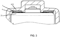
Fig. 3 is an enlarged schematic view of part A of the throttle shown inFig. 2 ; -
Fig. 4 is a schematic perspective view of the cover of the throttle shown inFig. 1 ; -
Fig. 5 is a schematic perspective view of another embodiment of the throttle of the present device, wherein the cover has been removed. - Referring to
Figs. 1 and2 , the throttle comprises: ahousing 1, the material thereof being metal, and thehousing 1 having a throttle throat; a cover 8 mated with thehousing 1, the material of the cover 8 being plastic, and anelectric machine 2 located in the cover 8; a torque transfer apparatus 3 meshed with anoutput end 20 of theelectric machine 2; athrottle shaft 4 connected in a fixed manner to the torque transfer apparatus 3, thethrottle shaft 4 passing through the throttle throat, and being supported by being inserted into a first mounting hole (not shown in the figures) and a second mounting hole (not shown in the figures) in thehousing 1; and abutterfly valve 5 mounted on thethrottle shaft 4 and located inside the throttle throat. - Since the
electric machine 2 is located in the cover 8, there is no need for a chamber for accommodating theelectric machine 2 to be provided in thehousing 1 made of metal material, so material costs are reduced. Furthermore, the cover 8 may be injection molded first, wherein the cover 8 has abody 81, achamber 82 which is formed as an extension from thebody 81 and used for accommodating theelectric machine 2, and screw holes (not shown in the figures) for fixing the electric machine, and then theelectric machine 2 may be fixed in thechamber 82 by means of screws. Thus, there is no need for thechamber 82 and screw holes for fixing theelectric machine 2 to be formed in the cover 8 by machining; injection molding may be used, so processing costs are reduced. Referring toFig. 4 ,ridges 821 are provided on an inside wall of thechamber 82; theridges 821 press against theelectric machine 2, thereby avoiding transverse vibration of theelectric machine 2 during operation, and at the same time helping to dissipate heat. Referring toFig. 3 , theelectric machine 2 has atop 21; awave washer 6 and a flat washer 7 are provided between thetop 21 and atop wall 822 of thechamber 82. The wave washer 6 presses against thetop 21 of theelectric machine 2, thereby reducing axial vibration of theelectric machine 2; the flat washer 7 is located between thewave washer 6 and thetop wall 822 of thechamber 82, to prevent stress caused by thewave washer 6 from damaging the cover 8. An outside wall of thechamber 82 is provided with ribs 823 which extend to thebody 81; the ribs can increase the rigidity of the cover 8, reduce transverse deformation, and thereby reduce transverse vibration of theelectric machine 2. To dissipate heat better, a thermally conductive adhesive may be provided between thehousing 1 and the cover 8. - Referring to
Fig. 2 , the torque transfer apparatus 3 is two-stage transmission, comprising afirst gear 31 and asecond gear 32 meshed with each other, thefirst gear 31 being mounted on an axle and meshed with theoutput end 20 of theelectric machine 2, and thesecond gear 32 being connected in a fixed manner to thethrottle shaft 4. The throttle also comprises a return spring 12 with two ends fixed to thehousing 1 and thesecond gear 32 respectively. The return spring 12 is mounted on thehousing 1 andsecond gear 32 with a certain preload. Due to the action of the preload, one end of the return spring 12 will pull the second gear 12 and fix it to thehousing 1; this position is an initial position of thesecond gear 32. When a break in current is encountered, under the action of the preload the return spring 12 can pull thesecond gear 32 to rotate, thereby impelling thethrottle shaft 4 to rotate and pull thebutterfly valve 5 back to an initial position. - Referring to
Figs. 1 and4 , the cover 8 has anelectrical connection port 84 and aposition sensor 86 located therein. Theposition sensor 86 senses a rotation angle of thebutterfly valve 5 through a change in a magnetic field of a magnet (not shown in the figures), and provides feedback to an electronic control unit. - Referring to
Fig. 5 , optionally, the torque transfer apparatus 3 is one-stage transmission; the torque transfer apparatus 3 is asingle gear 30 connected in a fixed manner to thethrottle shaft 4, with thegear 30 being meshed with theoutput end 20 of theelectric machine 2, and at the same time being connected in a fixed manner to thethrottle shaft 4. In this embodiment, thegear 30 is meshed internally with theoutput end 20 of theelectric machine 2, but could also be meshed externally. Thus the number of components is small, the assembly process is more simple, and the space occupied is smaller. - Optionally, after the cover 8 has been injection molded, the
electric machine 2 is fixed in the chamber by means of glue. Theelectric machine 2 could also be fixed in the cover 8 directly by injection molding. These two methods of fixing the electric machine solve the problems of vibration and heat dissipation very well. - Although the present device has been disclosed above through preferred embodiments, it is by no means limited to these. Changes and amendments of all kinds made within the spirit and scope of the present device by any person skilled in the art shall be included in the scope of protection of the present device. Thus the scope of protection of the present device shall be the scope defined by the claims.
Claims (10)
- A throttle, comprising:a housing, having a throttle throat;a cover mated with the housing, the material of the cover being plastic;an electric machine;a torque transfer apparatus meshed with an output end of the electric machine;a throttle shaft connected in a fixed manner to the torque transfer apparatus, the throttle shaft passing through the throttle throat, and being supported by being inserted into a first mounting hole and a second mounting hole in the throttle housing;a butterfly valve mounted on the throttle shaft and located inside the throttle throat;wherein the electric machine is located in the cover.
- The throttle as claimed in claim 1, wherein the cover has a body and a chamber which is formed as an extension from the body and used for accommodating the electric machine, the electric machine being mounted in the chamber by means of screws.
- The throttle as claimed in claim 2, wherein an inside wall of the chamber is provided with a ridge which presses against the electric machine.
- The throttle as claimed in claim 2, wherein the electric machine has a top; a wave washer and a flat washer are provided between the top and a top wall of the chamber; the wave washer presses against the top end of the electric machine, and the flat washer is located between the wave washer and the top wall of the chamber.
- The throttle as claimed in claim 2, wherein an outside wall of the chamber is provided with a rib extending to the body.
- The throttle as claimed in claim 2, wherein the electric machine is fixed in the chamber by means of glue.
- The throttle as claimed in claim 1, wherein the electric machine is fixed in the cover by injection molding.
- The throttle as claimed in claim 1, wherein thermally conductive adhesive is provided between the housing and the cover.
- The throttle as claimed in any one of claims 1 - 8, wherein the torque transfer apparatus is two-stage transmission, comprising a first gear and a second gear meshed with each other, the first gear being mounted on an axle and meshed with the output end of the electric machine, and the second gear being connected in a fixed manner to the throttle shaft.
- The throttle as claimed in any one of claims 1 - 8, wherein the torque transfer apparatus is one-stage transmission; the torque transfer apparatus is a single gear connected in a fixed manner to the throttle shaft, with the gear being meshed with the output end of the electric machine.
Applications Claiming Priority (1)
| Application Number | Priority Date | Filing Date | Title |
|---|---|---|---|
| CN201620433790.7U CN205605313U (en) | 2016-05-12 | 2016-05-12 | Air throttle |
Publications (2)
| Publication Number | Publication Date |
|---|---|
| EP3244041A1 true EP3244041A1 (en) | 2017-11-15 |
| EP3244041B1 EP3244041B1 (en) | 2023-07-12 |
Family
ID=56967511
Family Applications (1)
| Application Number | Title | Priority Date | Filing Date |
|---|---|---|---|
| EP17169845.9A Active EP3244041B1 (en) | 2016-05-12 | 2017-05-08 | Throttle |
Country Status (2)
| Country | Link |
|---|---|
| EP (1) | EP3244041B1 (en) |
| CN (1) | CN205605313U (en) |
Cited By (1)
| Publication number | Priority date | Publication date | Assignee | Title |
|---|---|---|---|---|
| EP3855007A4 (en) * | 2018-10-03 | 2021-12-29 | Yamaha Hatsudoki Kabushiki Kaisha | Saddle-type vehicle |
Families Citing this family (1)
| Publication number | Priority date | Publication date | Assignee | Title |
|---|---|---|---|---|
| CN107196446A (en) * | 2017-07-21 | 2017-09-22 | 无锡隆盛科技股份有限公司 | The motor aseismatic mechanism of low pressure EGR valve |
Citations (6)
| Publication number | Priority date | Publication date | Assignee | Title |
|---|---|---|---|---|
| JP2007278123A (en) * | 2006-04-04 | 2007-10-25 | Aisan Ind Co Ltd | Throttle valve control device |
| US20090205611A1 (en) * | 2008-02-19 | 2009-08-20 | Mitsubishi Electric Corporation | Electronically-controlled throttle body |
| DE102011085048A1 (en) * | 2011-10-21 | 2013-04-25 | Robert Bosch Gmbh | throttling device |
| DE102012202507A1 (en) * | 2012-02-17 | 2013-08-22 | Mahle International Gmbh | Actuator for exhaust gas tract of internal combustion engine of motor car, has electric motor that is inserted into cylindrical motor receiving space, and conical fixing ring which is provided between electric motor and housing |
| DE102013101938A1 (en) * | 2013-02-27 | 2014-08-28 | Pierburg Gmbh | Drive arrangement for an engine of an internal combustion engine and exhaust gas recirculation valve |
| US20140261307A1 (en) * | 2013-03-13 | 2014-09-18 | Keihin Corporation | Engine intake control apparatus |
-
2016
- 2016-05-12 CN CN201620433790.7U patent/CN205605313U/en active Active
-
2017
- 2017-05-08 EP EP17169845.9A patent/EP3244041B1/en active Active
Patent Citations (6)
| Publication number | Priority date | Publication date | Assignee | Title |
|---|---|---|---|---|
| JP2007278123A (en) * | 2006-04-04 | 2007-10-25 | Aisan Ind Co Ltd | Throttle valve control device |
| US20090205611A1 (en) * | 2008-02-19 | 2009-08-20 | Mitsubishi Electric Corporation | Electronically-controlled throttle body |
| DE102011085048A1 (en) * | 2011-10-21 | 2013-04-25 | Robert Bosch Gmbh | throttling device |
| DE102012202507A1 (en) * | 2012-02-17 | 2013-08-22 | Mahle International Gmbh | Actuator for exhaust gas tract of internal combustion engine of motor car, has electric motor that is inserted into cylindrical motor receiving space, and conical fixing ring which is provided between electric motor and housing |
| DE102013101938A1 (en) * | 2013-02-27 | 2014-08-28 | Pierburg Gmbh | Drive arrangement for an engine of an internal combustion engine and exhaust gas recirculation valve |
| US20140261307A1 (en) * | 2013-03-13 | 2014-09-18 | Keihin Corporation | Engine intake control apparatus |
Cited By (1)
| Publication number | Priority date | Publication date | Assignee | Title |
|---|---|---|---|---|
| EP3855007A4 (en) * | 2018-10-03 | 2021-12-29 | Yamaha Hatsudoki Kabushiki Kaisha | Saddle-type vehicle |
Also Published As
| Publication number | Publication date |
|---|---|
| CN205605313U (en) | 2016-09-28 |
| EP3244041B1 (en) | 2023-07-12 |
Similar Documents
| Publication | Publication Date | Title |
|---|---|---|
| KR101505327B1 (en) | Terminal arrangement device | |
| US8157542B2 (en) | Brushless motor fuel pump with control electronics arrangement | |
| CN110771017A (en) | Electric drive unit with housing | |
| CN105604932B (en) | G rotor pump group parts | |
| CN111600431B (en) | Electric oil pump | |
| CN105742853A (en) | Blind electrical connector to printed circuit board in housing | |
| EP3244041B1 (en) | Throttle | |
| EP3260682A1 (en) | Electric supercharger | |
| EP3842734B1 (en) | Electronically controlled throttle device for engine | |
| JP2009177869A (en) | Motor unit circuit board fixing structure | |
| CN105649999A (en) | Automobile electronic pump | |
| CN205101242U (en) | Auto electric water pump | |
| CN212968133U (en) | Circuit board assembly structure of pump device, pump device and vehicle | |
| CN205605314U (en) | Air throttle | |
| CN119945035A (en) | A buffer vibration isolation structure for a brushless blower motor | |
| CN205638709U (en) | Air throttle | |
| JP6926687B2 (en) | Electronic device | |
| CN207111249U (en) | Air throttle | |
| CN206860299U (en) | Air throttle | |
| CN116163963A (en) | Electronic water pump, assembly method of electronic water pump and new energy automobile | |
| EP3853457B1 (en) | Throttle valve and vehicle | |
| CN211116283U (en) | An EFI throttle valve | |
| CN108506077A (en) | A kind of cooling component | |
| CN209692522U (en) | Connection structure of motor and pump head, compressor and refrigeration plant | |
| CN206246241U (en) | Air throttle |
Legal Events
| Date | Code | Title | Description |
|---|---|---|---|
| PUAI | Public reference made under article 153(3) epc to a published international application that has entered the european phase |
Free format text: ORIGINAL CODE: 0009012 |
|
| STAA | Information on the status of an ep patent application or granted ep patent |
Free format text: STATUS: THE APPLICATION HAS BEEN PUBLISHED |
|
| AK | Designated contracting states |
Kind code of ref document: A1 Designated state(s): AL AT BE BG CH CY CZ DE DK EE ES FI FR GB GR HR HU IE IS IT LI LT LU LV MC MK MT NL NO PL PT RO RS SE SI SK SM TR |
|
| AX | Request for extension of the european patent |
Extension state: BA ME |
|
| STAA | Information on the status of an ep patent application or granted ep patent |
Free format text: STATUS: REQUEST FOR EXAMINATION WAS MADE |
|
| 17P | Request for examination filed |
Effective date: 20180515 |
|
| RBV | Designated contracting states (corrected) |
Designated state(s): AL AT BE BG CH CY CZ DE DK EE ES FI FR GB GR HR HU IE IS IT LI LT LU LV MC MK MT NL NO PL PT RO RS SE SI SK SM TR |
|
| RAP1 | Party data changed (applicant data changed or rights of an application transferred) |
Owner name: VITESCO TECHNOLOGIES GMBH |
|
| STAA | Information on the status of an ep patent application or granted ep patent |
Free format text: STATUS: EXAMINATION IS IN PROGRESS |
|
| 17Q | First examination report despatched |
Effective date: 20210512 |
|
| RAP3 | Party data changed (applicant data changed or rights of an application transferred) |
Owner name: VITESCO TECHNOLOGIES GMBH |
|
| GRAP | Despatch of communication of intention to grant a patent |
Free format text: ORIGINAL CODE: EPIDOSNIGR1 |
|
| STAA | Information on the status of an ep patent application or granted ep patent |
Free format text: STATUS: GRANT OF PATENT IS INTENDED |
|
| INTG | Intention to grant announced |
Effective date: 20221214 |
|
| GRAS | Grant fee paid |
Free format text: ORIGINAL CODE: EPIDOSNIGR3 |
|
| GRAA | (expected) grant |
Free format text: ORIGINAL CODE: 0009210 |
|
| STAA | Information on the status of an ep patent application or granted ep patent |
Free format text: STATUS: THE PATENT HAS BEEN GRANTED |
|
| AK | Designated contracting states |
Kind code of ref document: B1 Designated state(s): AL AT BE BG CH CY CZ DE DK EE ES FI FR GB GR HR HU IE IS IT LI LT LU LV MC MK MT NL NO PL PT RO RS SE SI SK SM TR |
|
| P01 | Opt-out of the competence of the unified patent court (upc) registered |
Effective date: 20230530 |
|
| REG | Reference to a national code |
Ref country code: CH Ref legal event code: EP |
|
| REG | Reference to a national code |
Ref country code: IE Ref legal event code: FG4D |
|
| REG | Reference to a national code |
Ref country code: DE Ref legal event code: R096 Ref document number: 602017071127 Country of ref document: DE |
|
| REG | Reference to a national code |
Ref country code: LT Ref legal event code: MG9D |
|
| REG | Reference to a national code |
Ref country code: NL Ref legal event code: MP Effective date: 20230712 |
|
| REG | Reference to a national code |
Ref country code: AT Ref legal event code: MK05 Ref document number: 1587407 Country of ref document: AT Kind code of ref document: T Effective date: 20230712 |
|
| PG25 | Lapsed in a contracting state [announced via postgrant information from national office to epo] |
Ref country code: NL Free format text: LAPSE BECAUSE OF FAILURE TO SUBMIT A TRANSLATION OF THE DESCRIPTION OR TO PAY THE FEE WITHIN THE PRESCRIBED TIME-LIMIT Effective date: 20230712 |
|
| PG25 | Lapsed in a contracting state [announced via postgrant information from national office to epo] |
Ref country code: GR Free format text: LAPSE BECAUSE OF FAILURE TO SUBMIT A TRANSLATION OF THE DESCRIPTION OR TO PAY THE FEE WITHIN THE PRESCRIBED TIME-LIMIT Effective date: 20231013 |
|
| PG25 | Lapsed in a contracting state [announced via postgrant information from national office to epo] |
Ref country code: ES Free format text: LAPSE BECAUSE OF FAILURE TO SUBMIT A TRANSLATION OF THE DESCRIPTION OR TO PAY THE FEE WITHIN THE PRESCRIBED TIME-LIMIT Effective date: 20230712 |
|
| PG25 | Lapsed in a contracting state [announced via postgrant information from national office to epo] |
Ref country code: IS Free format text: LAPSE BECAUSE OF FAILURE TO SUBMIT A TRANSLATION OF THE DESCRIPTION OR TO PAY THE FEE WITHIN THE PRESCRIBED TIME-LIMIT Effective date: 20231112 |
|
| PG25 | Lapsed in a contracting state [announced via postgrant information from national office to epo] |
Ref country code: SE Free format text: LAPSE BECAUSE OF FAILURE TO SUBMIT A TRANSLATION OF THE DESCRIPTION OR TO PAY THE FEE WITHIN THE PRESCRIBED TIME-LIMIT Effective date: 20230712 Ref country code: RS Free format text: LAPSE BECAUSE OF FAILURE TO SUBMIT A TRANSLATION OF THE DESCRIPTION OR TO PAY THE FEE WITHIN THE PRESCRIBED TIME-LIMIT Effective date: 20230712 Ref country code: PT Free format text: LAPSE BECAUSE OF FAILURE TO SUBMIT A TRANSLATION OF THE DESCRIPTION OR TO PAY THE FEE WITHIN THE PRESCRIBED TIME-LIMIT Effective date: 20231113 Ref country code: NO Free format text: LAPSE BECAUSE OF FAILURE TO SUBMIT A TRANSLATION OF THE DESCRIPTION OR TO PAY THE FEE WITHIN THE PRESCRIBED TIME-LIMIT Effective date: 20231012 Ref country code: LV Free format text: LAPSE BECAUSE OF FAILURE TO SUBMIT A TRANSLATION OF THE DESCRIPTION OR TO PAY THE FEE WITHIN THE PRESCRIBED TIME-LIMIT Effective date: 20230712 Ref country code: LT Free format text: LAPSE BECAUSE OF FAILURE TO SUBMIT A TRANSLATION OF THE DESCRIPTION OR TO PAY THE FEE WITHIN THE PRESCRIBED TIME-LIMIT Effective date: 20230712 Ref country code: IS Free format text: LAPSE BECAUSE OF FAILURE TO SUBMIT A TRANSLATION OF THE DESCRIPTION OR TO PAY THE FEE WITHIN THE PRESCRIBED TIME-LIMIT Effective date: 20231112 Ref country code: HR Free format text: LAPSE BECAUSE OF FAILURE TO SUBMIT A TRANSLATION OF THE DESCRIPTION OR TO PAY THE FEE WITHIN THE PRESCRIBED TIME-LIMIT Effective date: 20230712 Ref country code: GR Free format text: LAPSE BECAUSE OF FAILURE TO SUBMIT A TRANSLATION OF THE DESCRIPTION OR TO PAY THE FEE WITHIN THE PRESCRIBED TIME-LIMIT Effective date: 20231013 Ref country code: FI Free format text: LAPSE BECAUSE OF FAILURE TO SUBMIT A TRANSLATION OF THE DESCRIPTION OR TO PAY THE FEE WITHIN THE PRESCRIBED TIME-LIMIT Effective date: 20230712 Ref country code: ES Free format text: LAPSE BECAUSE OF FAILURE TO SUBMIT A TRANSLATION OF THE DESCRIPTION OR TO PAY THE FEE WITHIN THE PRESCRIBED TIME-LIMIT Effective date: 20230712 Ref country code: AT Free format text: LAPSE BECAUSE OF FAILURE TO SUBMIT A TRANSLATION OF THE DESCRIPTION OR TO PAY THE FEE WITHIN THE PRESCRIBED TIME-LIMIT Effective date: 20230712 |
|
| PG25 | Lapsed in a contracting state [announced via postgrant information from national office to epo] |
Ref country code: PL Free format text: LAPSE BECAUSE OF FAILURE TO SUBMIT A TRANSLATION OF THE DESCRIPTION OR TO PAY THE FEE WITHIN THE PRESCRIBED TIME-LIMIT Effective date: 20230712 |
|
| REG | Reference to a national code |
Ref country code: DE Ref legal event code: R097 Ref document number: 602017071127 Country of ref document: DE |
|
| PG25 | Lapsed in a contracting state [announced via postgrant information from national office to epo] |
Ref country code: SM Free format text: LAPSE BECAUSE OF FAILURE TO SUBMIT A TRANSLATION OF THE DESCRIPTION OR TO PAY THE FEE WITHIN THE PRESCRIBED TIME-LIMIT Effective date: 20230712 Ref country code: RO Free format text: LAPSE BECAUSE OF FAILURE TO SUBMIT A TRANSLATION OF THE DESCRIPTION OR TO PAY THE FEE WITHIN THE PRESCRIBED TIME-LIMIT Effective date: 20230712 Ref country code: EE Free format text: LAPSE BECAUSE OF FAILURE TO SUBMIT A TRANSLATION OF THE DESCRIPTION OR TO PAY THE FEE WITHIN THE PRESCRIBED TIME-LIMIT Effective date: 20230712 Ref country code: DK Free format text: LAPSE BECAUSE OF FAILURE TO SUBMIT A TRANSLATION OF THE DESCRIPTION OR TO PAY THE FEE WITHIN THE PRESCRIBED TIME-LIMIT Effective date: 20230712 Ref country code: CZ Free format text: LAPSE BECAUSE OF FAILURE TO SUBMIT A TRANSLATION OF THE DESCRIPTION OR TO PAY THE FEE WITHIN THE PRESCRIBED TIME-LIMIT Effective date: 20230712 Ref country code: SK Free format text: LAPSE BECAUSE OF FAILURE TO SUBMIT A TRANSLATION OF THE DESCRIPTION OR TO PAY THE FEE WITHIN THE PRESCRIBED TIME-LIMIT Effective date: 20230712 |
|
| PLBE | No opposition filed within time limit |
Free format text: ORIGINAL CODE: 0009261 |
|
| STAA | Information on the status of an ep patent application or granted ep patent |
Free format text: STATUS: NO OPPOSITION FILED WITHIN TIME LIMIT |
|
| PG25 | Lapsed in a contracting state [announced via postgrant information from national office to epo] |
Ref country code: IT Free format text: LAPSE BECAUSE OF FAILURE TO SUBMIT A TRANSLATION OF THE DESCRIPTION OR TO PAY THE FEE WITHIN THE PRESCRIBED TIME-LIMIT Effective date: 20230712 |
|
| 26N | No opposition filed |
Effective date: 20240415 |
|
| PG25 | Lapsed in a contracting state [announced via postgrant information from national office to epo] |
Ref country code: SI Free format text: LAPSE BECAUSE OF FAILURE TO SUBMIT A TRANSLATION OF THE DESCRIPTION OR TO PAY THE FEE WITHIN THE PRESCRIBED TIME-LIMIT Effective date: 20230712 |
|
| PG25 | Lapsed in a contracting state [announced via postgrant information from national office to epo] |
Ref country code: BG Free format text: LAPSE BECAUSE OF FAILURE TO SUBMIT A TRANSLATION OF THE DESCRIPTION OR TO PAY THE FEE WITHIN THE PRESCRIBED TIME-LIMIT Effective date: 20230712 |
|
| PG25 | Lapsed in a contracting state [announced via postgrant information from national office to epo] |
Ref country code: BG Free format text: LAPSE BECAUSE OF FAILURE TO SUBMIT A TRANSLATION OF THE DESCRIPTION OR TO PAY THE FEE WITHIN THE PRESCRIBED TIME-LIMIT Effective date: 20230712 |
|
| REG | Reference to a national code |
Ref country code: CH Ref legal event code: PL |
|
| PG25 | Lapsed in a contracting state [announced via postgrant information from national office to epo] |
Ref country code: MC Free format text: LAPSE BECAUSE OF FAILURE TO SUBMIT A TRANSLATION OF THE DESCRIPTION OR TO PAY THE FEE WITHIN THE PRESCRIBED TIME-LIMIT Effective date: 20230712 |
|
| PG25 | Lapsed in a contracting state [announced via postgrant information from national office to epo] |
Ref country code: LU Free format text: LAPSE BECAUSE OF NON-PAYMENT OF DUE FEES Effective date: 20240508 |
|
| GBPC | Gb: european patent ceased through non-payment of renewal fee |
Effective date: 20240508 |
|
| PG25 | Lapsed in a contracting state [announced via postgrant information from national office to epo] |
Ref country code: MC Free format text: LAPSE BECAUSE OF FAILURE TO SUBMIT A TRANSLATION OF THE DESCRIPTION OR TO PAY THE FEE WITHIN THE PRESCRIBED TIME-LIMIT Effective date: 20230712 Ref country code: LU Free format text: LAPSE BECAUSE OF NON-PAYMENT OF DUE FEES Effective date: 20240508 Ref country code: CH Free format text: LAPSE BECAUSE OF NON-PAYMENT OF DUE FEES Effective date: 20240531 |
|
| REG | Reference to a national code |
Ref country code: BE Ref legal event code: MM Effective date: 20240531 |
|
| REG | Reference to a national code |
Ref country code: DE Ref legal event code: R081 Ref document number: 602017071127 Country of ref document: DE Owner name: SCHAEFFLER TECHNOLOGIES AG & CO. KG, DE Free format text: FORMER OWNER: VITESCO TECHNOLOGIES GMBH, 93055 REGENSBURG, DE |
|
| PG25 | Lapsed in a contracting state [announced via postgrant information from national office to epo] |
Ref country code: IE Free format text: LAPSE BECAUSE OF NON-PAYMENT OF DUE FEES Effective date: 20240508 |
|
| PG25 | Lapsed in a contracting state [announced via postgrant information from national office to epo] |
Ref country code: BE Free format text: LAPSE BECAUSE OF NON-PAYMENT OF DUE FEES Effective date: 20240531 |
|
| PG25 | Lapsed in a contracting state [announced via postgrant information from national office to epo] |
Ref country code: FR Free format text: LAPSE BECAUSE OF NON-PAYMENT OF DUE FEES Effective date: 20240531 |
|
| PG25 | Lapsed in a contracting state [announced via postgrant information from national office to epo] |
Ref country code: GB Free format text: LAPSE BECAUSE OF NON-PAYMENT OF DUE FEES Effective date: 20240508 |
|
| PGFP | Annual fee paid to national office [announced via postgrant information from national office to epo] |
Ref country code: DE Payment date: 20250531 Year of fee payment: 9 |
|
| PG25 | Lapsed in a contracting state [announced via postgrant information from national office to epo] |
Ref country code: CY Free format text: LAPSE BECAUSE OF FAILURE TO SUBMIT A TRANSLATION OF THE DESCRIPTION OR TO PAY THE FEE WITHIN THE PRESCRIBED TIME-LIMIT; INVALID AB INITIO Effective date: 20170508 |
|
| PG25 | Lapsed in a contracting state [announced via postgrant information from national office to epo] |
Ref country code: HU Free format text: LAPSE BECAUSE OF FAILURE TO SUBMIT A TRANSLATION OF THE DESCRIPTION OR TO PAY THE FEE WITHIN THE PRESCRIBED TIME-LIMIT; INVALID AB INITIO Effective date: 20170508 |