EP3244015B1 - Stator vane shiplap seal assembly - Google Patents
Stator vane shiplap seal assembly Download PDFInfo
- Publication number
- EP3244015B1 EP3244015B1 EP17156355.4A EP17156355A EP3244015B1 EP 3244015 B1 EP3244015 B1 EP 3244015B1 EP 17156355 A EP17156355 A EP 17156355A EP 3244015 B1 EP3244015 B1 EP 3244015B1
- Authority
- EP
- European Patent Office
- Prior art keywords
- shiplap
- stator
- female
- male
- aftward
- Prior art date
- Legal status (The legal status is an assumption and is not a legal conclusion. Google has not performed a legal analysis and makes no representation as to the accuracy of the status listed.)
- Active
Links
- 210000003746 feather Anatomy 0.000 claims description 21
- 239000011800 void material Substances 0.000 claims description 7
- 230000000295 complement effect Effects 0.000 claims description 4
- 239000007789 gas Substances 0.000 description 18
- 238000000034 method Methods 0.000 description 7
- 150000001875 compounds Chemical class 0.000 description 5
- 230000008878 coupling Effects 0.000 description 4
- 238000010168 coupling process Methods 0.000 description 4
- 238000005859 coupling reaction Methods 0.000 description 4
- 229910052751 metal Inorganic materials 0.000 description 4
- 239000002184 metal Substances 0.000 description 4
- 230000000712 assembly Effects 0.000 description 3
- 238000000429 assembly Methods 0.000 description 3
- 238000002485 combustion reaction Methods 0.000 description 3
- 238000009760 electrical discharge machining Methods 0.000 description 3
- 239000000463 material Substances 0.000 description 3
- 238000007789 sealing Methods 0.000 description 3
- 239000000446 fuel Substances 0.000 description 2
- 229910018487 Ni—Cr Inorganic materials 0.000 description 1
- 229910000831 Steel Inorganic materials 0.000 description 1
- 230000006978 adaptation Effects 0.000 description 1
- 239000000956 alloy Substances 0.000 description 1
- 229910045601 alloy Inorganic materials 0.000 description 1
- -1 but not limited to Substances 0.000 description 1
- VNNRSPGTAMTISX-UHFFFAOYSA-N chromium nickel Chemical compound [Cr].[Ni] VNNRSPGTAMTISX-UHFFFAOYSA-N 0.000 description 1
- 239000000567 combustion gas Substances 0.000 description 1
- 238000004891 communication Methods 0.000 description 1
- 230000006835 compression Effects 0.000 description 1
- 238000007906 compression Methods 0.000 description 1
- 238000010276 construction Methods 0.000 description 1
- 238000001816 cooling Methods 0.000 description 1
- 230000001419 dependent effect Effects 0.000 description 1
- 239000007769 metal material Substances 0.000 description 1
- 239000010959 steel Substances 0.000 description 1
Images
Classifications
-
- F—MECHANICAL ENGINEERING; LIGHTING; HEATING; WEAPONS; BLASTING
- F01—MACHINES OR ENGINES IN GENERAL; ENGINE PLANTS IN GENERAL; STEAM ENGINES
- F01D—NON-POSITIVE DISPLACEMENT MACHINES OR ENGINES, e.g. STEAM TURBINES
- F01D11/00—Preventing or minimising internal leakage of working-fluid, e.g. between stages
- F01D11/005—Sealing means between non relatively rotating elements
-
- F—MECHANICAL ENGINEERING; LIGHTING; HEATING; WEAPONS; BLASTING
- F01—MACHINES OR ENGINES IN GENERAL; ENGINE PLANTS IN GENERAL; STEAM ENGINES
- F01D—NON-POSITIVE DISPLACEMENT MACHINES OR ENGINES, e.g. STEAM TURBINES
- F01D9/00—Stators
- F01D9/02—Nozzles; Nozzle boxes; Stator blades; Guide conduits, e.g. individual nozzles
- F01D9/04—Nozzles; Nozzle boxes; Stator blades; Guide conduits, e.g. individual nozzles forming ring or sector
- F01D9/041—Nozzles; Nozzle boxes; Stator blades; Guide conduits, e.g. individual nozzles forming ring or sector using blades
-
- F—MECHANICAL ENGINEERING; LIGHTING; HEATING; WEAPONS; BLASTING
- F05—INDEXING SCHEMES RELATING TO ENGINES OR PUMPS IN VARIOUS SUBCLASSES OF CLASSES F01-F04
- F05D—INDEXING SCHEME FOR ASPECTS RELATING TO NON-POSITIVE-DISPLACEMENT MACHINES OR ENGINES, GAS-TURBINES OR JET-PROPULSION PLANTS
- F05D2220/00—Application
- F05D2220/30—Application in turbines
- F05D2220/32—Application in turbines in gas turbines
-
- F—MECHANICAL ENGINEERING; LIGHTING; HEATING; WEAPONS; BLASTING
- F05—INDEXING SCHEMES RELATING TO ENGINES OR PUMPS IN VARIOUS SUBCLASSES OF CLASSES F01-F04
- F05D—INDEXING SCHEME FOR ASPECTS RELATING TO NON-POSITIVE-DISPLACEMENT MACHINES OR ENGINES, GAS-TURBINES OR JET-PROPULSION PLANTS
- F05D2230/00—Manufacture
- F05D2230/10—Manufacture by removing material
- F05D2230/12—Manufacture by removing material by spark erosion methods
-
- F—MECHANICAL ENGINEERING; LIGHTING; HEATING; WEAPONS; BLASTING
- F05—INDEXING SCHEMES RELATING TO ENGINES OR PUMPS IN VARIOUS SUBCLASSES OF CLASSES F01-F04
- F05D—INDEXING SCHEME FOR ASPECTS RELATING TO NON-POSITIVE-DISPLACEMENT MACHINES OR ENGINES, GAS-TURBINES OR JET-PROPULSION PLANTS
- F05D2230/00—Manufacture
- F05D2230/50—Building or constructing in particular ways
- F05D2230/51—Building or constructing in particular ways in a modular way, e.g. using several identical or complementary parts or features
-
- F—MECHANICAL ENGINEERING; LIGHTING; HEATING; WEAPONS; BLASTING
- F05—INDEXING SCHEMES RELATING TO ENGINES OR PUMPS IN VARIOUS SUBCLASSES OF CLASSES F01-F04
- F05D—INDEXING SCHEME FOR ASPECTS RELATING TO NON-POSITIVE-DISPLACEMENT MACHINES OR ENGINES, GAS-TURBINES OR JET-PROPULSION PLANTS
- F05D2240/00—Components
- F05D2240/10—Stators
- F05D2240/12—Fluid guiding means, e.g. vanes
-
- F—MECHANICAL ENGINEERING; LIGHTING; HEATING; WEAPONS; BLASTING
- F05—INDEXING SCHEMES RELATING TO ENGINES OR PUMPS IN VARIOUS SUBCLASSES OF CLASSES F01-F04
- F05D—INDEXING SCHEME FOR ASPECTS RELATING TO NON-POSITIVE-DISPLACEMENT MACHINES OR ENGINES, GAS-TURBINES OR JET-PROPULSION PLANTS
- F05D2240/00—Components
- F05D2240/55—Seals
Definitions
- the present disclosure relates to gas turbine engines, and more specifically, to a stator vane seal assembly for gas turbine engines.
- Gas turbine engines typically include a compressor section to pressurize inflowing air, a combustor section to burn a fuel in the presence of the pressurized air, and a turbine section to extract energy from the resulting combustion gases.
- the compressor section may include a plurality of rotor blades separated by a plurality of stator vane assemblies mounted within the engine casing.
- Each stator vane assembly may comprise one or more stator shrouds coupled together end to end to form an annular structure.
- a small, flat metal part (sometimes referred to as a feather seal) may be inserted horizontally between the connected ends of stator shrouds to minimize air flow leakage from the pressurized gas path.
- gaps on the radially inward and/or radially outward side of the feather seal may still exist as the adjacent stator shrouds separate due to thermal and gas loads, resulting in air flow leakage in the radial and axial direction. Air flow leakage may result in overall loss in performance to the gas turbine engine.
- a prior art stator vane shiplap seal assembly having the features of the preamble of claim 1 is disclosed in WO 2006/100256 .
- Other prior art stator vane shiplap seal assemblies are disclosed in EP 1,275,819 , JP H01 310 104 , US 2015/030443 , DE 10 2009 029587 , US 2010/129211 , US 2006/245715 and WO 2012/041651 .
- the present invention provides a stator vane ship lap seal assembly in accordance with claim 1.
- any of the method or process descriptions may be executed in any order and are not necessarily limited to the order presented.
- any reference to singular includes plural embodiments, and any reference to more than one component or step may include a singular embodiment or step.
- any reference to attached, fixed, coupled, connected or the like may include permanent, removable, temporary, partial, full and/or any other possible attachment option.
- any reference to without contact (or similar phrases) may also include reduced contact or minimal contact. Surface shading lines may be used throughout the figures to denote different parts but not necessarily to denote the same or different materials.
- tail refers to the direction associated with the tail (e.g., the back end) of an aircraft, or generally, to the direction of exhaust of the gas turbine engine.
- forward refers to the direction associated with the nose (e.g., the front end) of an aircraft, or generally, to the direction of flight or motion.
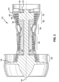
- Gas turbine engine 100 (such as a turbofan gas turbine engine) is illustrated.
- Gas turbine engine 100 is disposed about axial centerline axis 120, which may also be referred to as axis of rotation 120.
- Gas turbine engine 100 may comprise a fan 140, compressor sections 150 and 160, a combustion section 180, and turbine sections 190, 191.
- the fan 140 may drive air into compressor sections 150, 160, which may further drive air along a core flow path for compression and communication into the combustion section 180. Air compressed in the compressor sections 150, 160 may be mixed with fuel and burned in combustion section 180 and expanded across the turbine sections 190, 191.
- the turbine sections 190, 191 may include high pressure rotors 192 and low pressure rotors 194, which rotate in response to the expansion.
- the turbine sections 190, 191 may comprise alternating rows of rotary airfoils or rotor blades 196 and stator vane assemblies 198, housed within an engine casing 195. Cooling air may be supplied to the turbine sections 190, 191 from the compressor sections 150, 160.
- a plurality of bearings 115 may support spools in the gas turbine engine 100.
- FIG. 1 provides a general understanding of the sections in a gas turbine engine, and is not intended to limit the disclosure. The present disclosure may extend to all types of applications and to all types of turbine engines, including turbofan gas turbine engines and turbojet engines.
- stator vane shiplap seal assembly 200 is disclosed.
- Stator vane shiplap seal assembly 200 is configured to provide a seal between adjacent stator clusters.
- stator vane shiplap seal assembly 200 provides sealing against air flow leakage in both the axial direction and the radial direction (in relation to axis of rotation 120), in between adjacent stator clusters.
- stator vane shiplap seal assembly 200 may provide improved sealing against air flow leakage without the use of a feather seal, although a feather seal may also be implemented if so desired.
- stator vane shiplap seal assembly 200 provides a seal geometry through the use of a compound shiplap connection between adjacent stator clusters.
- a shiplap joint comprises an end-to-end connection wherein a first end of the connection is configured with a protrusion and a groove, and a second end of the connection is configured with complimentary protrusion and groove. The protrusion of the first end aligns with the groove of the second end, and the groove of the first end aligns with the protrusion of the second end, when forming the shiplap joint.
- a compound shiplap configuration comprises at least two shiplap joints on the same end: a shiplap joint to seal air flow along the radial direction, and a shiplap joint to seal air along the axial direction.
- the compound shiplap configuration may minimize the inter-segment gap between adjacent stator shrouds by creating overlap between the adjacent stator shrouds, further tending to minimize air flow leakage.
- the compound shiplap configuration may also tend to minimize air flow leakage by providing a more tortuous sealing path from which air may escape. In this regard, the twists and turns exhibited in a compound shiplap may inhibit the amount of air that may be leaked at a given time.
- stator vane shiplap seal assembly 200 may be located within any suitable location in gas turbine engine 100. Stator vane shiplap seal assembly 200 may couple to the inside of gas turbine engine 100 using any suitable method known in the art.
- stator vane shiplap seal assembly 200 may comprise a shroud tab located on a radially outward surface of stator vane shiplap seal assembly 200, configured to couple with a slot on the inside of gas turbine engine 100.
- Stator vane shiplap seal assembly 200 may be made and assembled using any suitable method in the art.
- Stator vane shiplap seal assembly 200 may also comprise any suitable material, such as a metallic material including, but not limited to, steel and/or an austenitic nickel-chromium-based alloy.
- Stator vane shiplap seal assembly 200 comprises at least one stator cluster 210.
- a plurality of stator clusters 210 may be coupled together, end to end, to form a full ring stator vane shiplap seal assembly 200 (as discussed previously).
- stator cluster 210 comprises a shiplap stator shroud 220 and at least one stator vane 290.
- the stator vane 290 is coupled to the radially inward surface of shiplap stator shroud 220, and disposed in an axial direction towards axis of rotation 120.
- Stator vanes 290 may comprise any suitable type of stator vane, and may couple to shiplap stator shroud 220 using any suitable method.
- shiplap stator shroud 220 may comprise any suitable stator shroud capable of coupling at one surface to the radially inward side of an engine casing, and operatively coupling at the opposite surface to stator vanes 290.
- Shiplap stator shroud 220 may also comprise any suitable anti-rotation mechanism on the surface coupled to the radially inward side of the engine casing, such as, for example, an anti-rotation slot and/or other similar type of anti-rotation mechanism.
- shiplap stator shroud 220 comprises a female end 230 and a male end 240.
- Female end 230 comprises the end surface of shiplap stator shroud 220, opposite of male end 240.
- Male end 240 likewise comprises the opposite end surface of shiplap stator shroud 220.
- Female end 230 is configured to operatively couple to male end 240 of a second shiplap stator shroud.
- stator vane shiplap seal assembly 200 is formed by coupling female end 230 of a first shiplap stator shroud to male end 240 of a second adjacent shiplap stator shroud.
- Female end 230 comprises a female forward shiplap surface 234 and a female aftward shiplap surface 238.
- Female forward shiplap surface 234 comprises a portion of female end 230 located on an axially aftward edge of shiplap stator shroud 220 and formed as a shiplap joint.
- Female aftward shiplap surface 238 comprises a portion of female end 230 located on a radially aftward edge of shiplap stator shroud 220 and formed as a shiplap joint.
- Female forward shiplap surface 234 and female aftward shiplap surface 238 may be formed into a shiplap joint using any suitable method.
- female forward shiplap surface 234 and female afward shiplap surface 238 may be milled or be otherwise machined down to form a shiplap joint.
- female forward shiplap surface 234 and female aftward shiplap surface 238 may be formed through electrical discharge machining ("EDM") wherein the desired shiplap joint is obtained by using electrical discharges to erode the metal surface of female end 230.
- EDM electrical discharge machining
- Male end 240 comprises a male forward shiplap surface 244 and a male aftward shiplap surface 248.
- Male forward shiplap surface 244 comprises a portion of male end 240 located on an axially aftward edge of shiplap stator shroud 220 and formed as a shiplap joint.
- Male aftward shiplap surface 248 comprises a portion of male end 240 located on a radially aftward edge of shiplap stator shroud 220 and formed as a shiplap joint.
- Male forward shiplap surface 244 and male aftward shiplap surface 248 may be formed into a complimentary shiplap joint using any suitable method.
- male forward shiplap surface 244 and male aftward shiplap surface 248 may be milled or be otherwise machined down to form a shiplap joint.
- male forward shiplap surface 244 and male aftward shiplap surface 248 may be formed through EDM, wherein the desired shiplap joint is obtained by using electrical discharges to erode the metal surface of male end 240.
- Female forward shiplap surface 234 is configured to operatively interface with male forward shiplap surface 244 when female end 230 is coupled to male end 240.
- female forward shiplap surface 234 is formed as a shiplap joint having a protrusion extending axially aftward from the surface of female end 230
- male forward shiplap surface 244 is formed as a shiplap joint comprising a void extending axially inward from the surface of male end 240.
- Female forward shiplap surface 234 is therefore complimentary to male forward shiplap surface 244, such that the protrusion defining female forward shiplap surface 234 operatively fits within the void defining male forward shiplap surface 244.
- Female forward shiplap surface 234 may also be formed as any suitable rabbet joint, i.e., a rectangular groove along a surface edge, with male forward shiplap surface 244 formed as a complimentary rabbet joint having a rectangular edge opposite of the rectangular groove of female forward shiplap surface 234.
- Female aftward shiplap surface 238 is configured to operatively interface with male aftward shiplap surface 248 when female end 230 is coupled to male end 240.
- female aftward shiplap surface 238 is formed as a shiplap joint comprising a void extending axially inward from the surface of female end 230
- male aftward shiplap surface 248 is formed as a shiplap joint comprising a protrusion extending axially aftward from the surface of male end 240.
- Female aftward shiplap surface 238 is therefore complementary to male aftward shiplap surface 248, such that the protrusion defining male aftward shiplap surface 248 operatively fits within the void defining female aftward shiplap surface 238.
- Female aftward shiplap surface 238 may also be formed as any suitable rabbet joint, i.e., a rectangular groove along a surface edge, with male aftward shiplap surface 248 formed as a complimentary rabbet joint having a rectangular edge opposite of the rectangular groove of female aftward shiplap surface 238.
- the geometry of the complementary shiplap joints in female forward shiplap surface 234 and male forward shiplap surface 244 and female aftward shiplap surface 238 and male aftward shiplap surface 248 may be varied to any suitable size and shape capable of minimizing air flow leakage by creating a more tortuous leakage path.
- an additional example of a shiplap stator vane assembly is provided.
- elements with like element numbering as depicted in FIGs. 2A-2D are intended to be the same and will not be repeated for the sake of clarity.
- stator vane shiplap seal assembly 400 may also comprise a feather seal 480.
- Feather seal 480 may be configured to further minimize air flow leakage in stator vane shiplap seal assembly 400.
- feather seal 480 may be located in any location suitable to minimize air flow leakage in stator vane shiplap seal assembly 400.
- a feather seal slot 485 may be configured to fit feather seal 480.
- Feather seal slot 485 may comprise a void machined into female end 430 and male end 440.
- Feather seal slot 485 may comprise any shape and size suitable to fit feather seal 480, such as, for example, a rectangular shape.
- Feather seal 480 may also be located within an inter-segment gap created by the coupling of adjacent shiplap stator shrouds.
- the use of feather seal 480 in feather seal slot 485 may further minimize air flow leakage in the radial direction (from axis of rotation 120).
- Feather seal 480 may comprise any shape, size, and material suitable to further minimize air flow leakage.
- feather seal 480 may comprise a small flat metal part, machined to size to fit within feather seal slot 485.
Description
- The present disclosure relates to gas turbine engines, and more specifically, to a stator vane seal assembly for gas turbine engines.
- Gas turbine engines typically include a compressor section to pressurize inflowing air, a combustor section to burn a fuel in the presence of the pressurized air, and a turbine section to extract energy from the resulting combustion gases. The compressor section may include a plurality of rotor blades separated by a plurality of stator vane assemblies mounted within the engine casing. Each stator vane assembly may comprise one or more stator shrouds coupled together end to end to form an annular structure. Typically, a small, flat metal part (sometimes referred to as a feather seal) may be inserted horizontally between the connected ends of stator shrouds to minimize air flow leakage from the pressurized gas path. However, gaps on the radially inward and/or radially outward side of the feather seal may still exist as the adjacent stator shrouds separate due to thermal and gas loads, resulting in air flow leakage in the radial and axial direction. Air flow leakage may result in overall loss in performance to the gas turbine engine.
- A prior art stator vane shiplap seal assembly having the features of the preamble of claim 1 is disclosed in
WO 2006/100256 . Other prior art stator vane shiplap seal assemblies are disclosed inEP 1,275,819 ,JP H01 310 104US 2015/030443 ,DE 10 2009 029587 ,US 2010/129211 ,US 2006/245715 andWO 2012/041651 . - The present invention provides a stator vane ship lap seal assembly in accordance with claim 1.
- Features of embodiments are recited in the dependent claims.
- The subject matter of the present disclosure is particularly pointed out and distinctly claimed in the concluding portion of the specification. A more complete understanding of the present disclosure, however, may best be obtained by referring to the detailed description and claims when considered in connection with the following illustrative figures. In the following figures, like reference numbers refer to similar elements and steps throughout the figures.
-
FIG. 1 illustrates a gas turbine engine, in accordance with various embodiments; -
FIG. 2A illustrates a perspective side view of a stator vane shiplap seal assembly, in accordance with various embodiments; -
FIG. 2B illustrates a perspective top view of a stator vane shiplap seal assembly, in accordance with various embodiments; -
FIG. 2C illustrates a perspective view of a female end of a stator vane shiplap seal assembly, in accordance with various embodiments; -
FIG. 2D illustrates a perspective view of a male end of a stator vane shiplap seal assembly, in accordance with various embodiments; -
FIG. 3A illustrates a perspective side view of a stator vane shiplap seal assembly, in accordance with various embodiments; -
FIG. 3B illustrates a perspective top view of a stator vane shiplap seal assembly, in accordance with various embodiments; and -
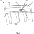
FIG. 4 illustrates a perspective side view of a stator vane shiplap seal assembly, in accordance with various embodiments. - Elements and steps in the figures are illustrated for simplicity and clarity and have not necessarily been rendered according to any particular sequence. For example, steps that may be performed concurrently or in different order are illustrated in the figures to help to improve understanding of embodiments of the present disclosure.
- The detailed description of exemplary embodiments herein makes reference to the accompanying drawings, which show exemplary embodiments by way of illustration. While these exemplary embodiments are described in sufficient detail to enable those skilled in the art to practice the disclosures, it should be understood that other embodiments may be realized and that logical changes and adaptations in design and construction may be made in accordance with this disclosure and the teachings herein. Thus, the detailed description herein is presented for purposes of illustration only and not of limitation.
- The scope of the disclosure is defined by the appended claims and their legal equivalents rather than by merely the examples described. For example, the steps recited in any of the method or process descriptions may be executed in any order and are not necessarily limited to the order presented. Furthermore, any reference to singular includes plural embodiments, and any reference to more than one component or step may include a singular embodiment or step. Also, any reference to attached, fixed, coupled, connected or the like may include permanent, removable, temporary, partial, full and/or any other possible attachment option. Additionally, any reference to without contact (or similar phrases) may also include reduced contact or minimal contact. Surface shading lines may be used throughout the figures to denote different parts but not necessarily to denote the same or different materials.
- As used herein, "aft" refers to the direction associated with the tail (e.g., the back end) of an aircraft, or generally, to the direction of exhaust of the gas turbine engine. As used herein, "forward" refers to the direction associated with the nose (e.g., the front end) of an aircraft, or generally, to the direction of flight or motion.
- In various embodiments, and with reference to
FIG. 1 , a gas turbine engine 100 (such as a turbofan gas turbine engine) is illustrated.Gas turbine engine 100 is disposed aboutaxial centerline axis 120, which may also be referred to as axis ofrotation 120.Gas turbine engine 100 may comprise afan 140,compressor sections combustion section 180, andturbine sections fan 140 may drive air intocompressor sections combustion section 180. Air compressed in thecompressor sections combustion section 180 and expanded across theturbine sections turbine sections high pressure rotors 192 andlow pressure rotors 194, which rotate in response to the expansion. Theturbine sections rotor blades 196 andstator vane assemblies 198, housed within anengine casing 195. Cooling air may be supplied to theturbine sections compressor sections bearings 115 may support spools in thegas turbine engine 100.FIG. 1 provides a general understanding of the sections in a gas turbine engine, and is not intended to limit the disclosure. The present disclosure may extend to all types of applications and to all types of turbine engines, including turbofan gas turbine engines and turbojet engines. - With reference to
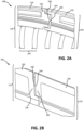
FIGs. 2A-2D , a stator vaneshiplap seal assembly 200 is disclosed. Stator vaneshiplap seal assembly 200 is configured to provide a seal between adjacent stator clusters. In this regard, stator vaneshiplap seal assembly 200 provides sealing against air flow leakage in both the axial direction and the radial direction (in relation to axis of rotation 120), in between adjacent stator clusters. Moreover, stator vaneshiplap seal assembly 200 may provide improved sealing against air flow leakage without the use of a feather seal, although a feather seal may also be implemented if so desired. - In accordance with the claims, stator vane
shiplap seal assembly 200 provides a seal geometry through the use of a compound shiplap connection between adjacent stator clusters. A shiplap joint comprises an end-to-end connection wherein a first end of the connection is configured with a protrusion and a groove, and a second end of the connection is configured with complimentary protrusion and groove. The protrusion of the first end aligns with the groove of the second end, and the groove of the first end aligns with the protrusion of the second end, when forming the shiplap joint. A compound shiplap configuration comprises at least two shiplap joints on the same end: a shiplap joint to seal air flow along the radial direction, and a shiplap joint to seal air along the axial direction. The compound shiplap configuration may minimize the inter-segment gap between adjacent stator shrouds by creating overlap between the adjacent stator shrouds, further tending to minimize air flow leakage. The compound shiplap configuration may also tend to minimize air flow leakage by providing a more tortuous sealing path from which air may escape. In this regard, the twists and turns exhibited in a compound shiplap may inhibit the amount of air that may be leaked at a given time. - In various embodiments, stator vane
shiplap seal assembly 200 may be located within any suitable location ingas turbine engine 100. Stator vaneshiplap seal assembly 200 may couple to the inside ofgas turbine engine 100 using any suitable method known in the art. For example, stator vaneshiplap seal assembly 200 may comprise a shroud tab located on a radially outward surface of stator vaneshiplap seal assembly 200, configured to couple with a slot on the inside ofgas turbine engine 100. Stator vaneshiplap seal assembly 200 may be made and assembled using any suitable method in the art. Stator vaneshiplap seal assembly 200 may also comprise any suitable material, such as a metallic material including, but not limited to, steel and/or an austenitic nickel-chromium-based alloy. - Stator vane
shiplap seal assembly 200 comprises at least onestator cluster 210. A plurality ofstator clusters 210 may be coupled together, end to end, to form a full ring stator vane shiplap seal assembly 200 (as discussed previously). In accordance with the claims,stator cluster 210 comprises ashiplap stator shroud 220 and at least onestator vane 290. Thestator vane 290 is coupled to the radially inward surface ofshiplap stator shroud 220, and disposed in an axial direction towards axis ofrotation 120.Stator vanes 290 may comprise any suitable type of stator vane, and may couple to shiplapstator shroud 220 using any suitable method. - In various embodiments,
shiplap stator shroud 220 may comprise any suitable stator shroud capable of coupling at one surface to the radially inward side of an engine casing, and operatively coupling at the opposite surface tostator vanes 290.Shiplap stator shroud 220 may also comprise any suitable anti-rotation mechanism on the surface coupled to the radially inward side of the engine casing, such as, for example, an anti-rotation slot and/or other similar type of anti-rotation mechanism. In accordance with the claims,shiplap stator shroud 220 comprises afemale end 230 and amale end 240.Female end 230 comprises the end surface ofshiplap stator shroud 220, opposite ofmale end 240.Male end 240 likewise comprises the opposite end surface ofshiplap stator shroud 220.Female end 230 is configured to operatively couple tomale end 240 of a second shiplap stator shroud. In this regard, stator vaneshiplap seal assembly 200 is formed by couplingfemale end 230 of a first shiplap stator shroud tomale end 240 of a second adjacent shiplap stator shroud. -
Female end 230 comprises a femaleforward shiplap surface 234 and a femaleaftward shiplap surface 238. Femaleforward shiplap surface 234 comprises a portion offemale end 230 located on an axially aftward edge ofshiplap stator shroud 220 and formed as a shiplap joint. Femaleaftward shiplap surface 238 comprises a portion offemale end 230 located on a radially aftward edge ofshiplap stator shroud 220 and formed as a shiplap joint. Femaleforward shiplap surface 234 and femaleaftward shiplap surface 238 may be formed into a shiplap joint using any suitable method. For example, femaleforward shiplap surface 234 and femaleafward shiplap surface 238 may be milled or be otherwise machined down to form a shiplap joint. Similarly, femaleforward shiplap surface 234 and femaleaftward shiplap surface 238 may be formed through electrical discharge machining ("EDM") wherein the desired shiplap joint is obtained by using electrical discharges to erode the metal surface offemale end 230. -
Male end 240 comprises a maleforward shiplap surface 244 and a maleaftward shiplap surface 248. Maleforward shiplap surface 244 comprises a portion ofmale end 240 located on an axially aftward edge ofshiplap stator shroud 220 and formed as a shiplap joint. Maleaftward shiplap surface 248 comprises a portion ofmale end 240 located on a radially aftward edge ofshiplap stator shroud 220 and formed as a shiplap joint. Maleforward shiplap surface 244 and maleaftward shiplap surface 248 may be formed into a complimentary shiplap joint using any suitable method. For example, maleforward shiplap surface 244 and maleaftward shiplap surface 248 may be milled or be otherwise machined down to form a shiplap joint. Similarly, maleforward shiplap surface 244 and maleaftward shiplap surface 248 may be formed through EDM, wherein the desired shiplap joint is obtained by using electrical discharges to erode the metal surface ofmale end 240. - Female
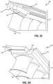
forward shiplap surface 234 is configured to operatively interface with maleforward shiplap surface 244 whenfemale end 230 is coupled tomale end 240. In this regard, femaleforward shiplap surface 234 is formed as a shiplap joint having a protrusion extending axially aftward from the surface offemale end 230, and maleforward shiplap surface 244 is formed as a shiplap joint comprising a void extending axially inward from the surface ofmale end 240. Femaleforward shiplap surface 234 is therefore complimentary to maleforward shiplap surface 244, such that the protrusion defining femaleforward shiplap surface 234 operatively fits within the void defining maleforward shiplap surface 244. Femaleforward shiplap surface 234 may also be formed as any suitable rabbet joint, i.e., a rectangular groove along a surface edge, with maleforward shiplap surface 244 formed as a complimentary rabbet joint having a rectangular edge opposite of the rectangular groove of femaleforward shiplap surface 234. - Female
aftward shiplap surface 238 is configured to operatively interface with maleaftward shiplap surface 248 whenfemale end 230 is coupled tomale end 240. In this regard, femaleaftward shiplap surface 238 is formed as a shiplap joint comprising a void extending axially inward from the surface offemale end 230, and maleaftward shiplap surface 248 is formed as a shiplap joint comprising a protrusion extending axially aftward from the surface ofmale end 240. Femaleaftward shiplap surface 238 is therefore complementary to maleaftward shiplap surface 248, such that the protrusion defining maleaftward shiplap surface 248 operatively fits within the void defining femaleaftward shiplap surface 238. Femaleaftward shiplap surface 238 may also be formed as any suitable rabbet joint, i.e., a rectangular groove along a surface edge, with maleaftward shiplap surface 248 formed as a complimentary rabbet joint having a rectangular edge opposite of the rectangular groove of femaleaftward shiplap surface 238. - The geometry of the complementary shiplap joints in female
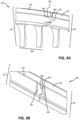
forward shiplap surface 234 and maleforward shiplap surface 244 and femaleaftward shiplap surface 238 and maleaftward shiplap surface 248 may be varied to any suitable size and shape capable of minimizing air flow leakage by creating a more tortuous leakage path. In various embodiments, and with reference toFIGs. 3A and 3B , an additional example of a shiplap stator vane assembly is provided. With respect toFIGs. 3A, 3B , and4 , elements with like element numbering as depicted inFIGs. 2A-2D are intended to be the same and will not be repeated for the sake of clarity. - In various embodiments and with reference to
FIG. 4 , stator vaneshiplap seal assembly 400 may also comprise afeather seal 480.Feather seal 480 may be configured to further minimize air flow leakage in stator vaneshiplap seal assembly 400. In this regard,feather seal 480 may be located in any location suitable to minimize air flow leakage in stator vaneshiplap seal assembly 400. For example, and in various embodiments, afeather seal slot 485 may be configured to fitfeather seal 480.Feather seal slot 485 may comprise a void machined intofemale end 430 andmale end 440.Feather seal slot 485 may comprise any shape and size suitable to fitfeather seal 480, such as, for example, a rectangular shape.Feather seal 480 may also be located within an inter-segment gap created by the coupling of adjacent shiplap stator shrouds. The use offeather seal 480 infeather seal slot 485 may further minimize air flow leakage in the radial direction (from axis of rotation 120).Feather seal 480 may comprise any shape, size, and material suitable to further minimize air flow leakage. For example,feather seal 480 may comprise a small flat metal part, machined to size to fit withinfeather seal slot 485.
Claims (5)
- A stator vane shiplap seal assembly (200; 300; 400), characterised by:
a first shiplap stator cluster (210; 310; 410) coupled to a second shiplap stator cluster (210; 310; 410), wherein each shiplap stator cluster (210; 310; 410) comprises:a shiplap stator shroud (220; 320; 420) having a radially outward surface and a radially inward surface, and a female end (230; 330; 430) circumferentially opposite a male end (240; 340; 440),wherein the female end (230; 330; 430) comprises a female forward shiplap surface (234; 334) and a female aftward shiplap surface (238; 338) along an axial direction, and the male end (240; 340; 440) comprises a male forward shiplap surface (244; 344) and a male aftward shiplap surface (248; 348) along the axial direction,wherein the female forward shiplap surface (234; 334) is complementary to the male forward shiplap surface (244; 344), forming a first shiplap seal in response to the first shiplap stator cluster (210; 310; 410) being coupled to the second shiplap stator cluster (210; 310; 410),wherein the female aftward shiplap surface (238; 338) is complementary to the male aftward shiplap surface (248; 348), forming a second shiplap seal in response to the first shiplap stator cluster (210; 310; 410) being coupled to the second shiplap stator cluster (210; 310; 410);wherein the female forward shiplap surface (234; 334) comprises a portion of the female end (230; 330; 430) formed as a shiplap joint having a circumferentially extending protrusion;wherein the male forward shiplap surface (244; 344) comprises a portion of the male end (240; 340; 440) formed as a shiplap joint comprising a circumferentially extending void;wherein the female aftward shiplap surface (238; 338) comprises a portion of the female end (230; 330; 430) formed as a shiplap joint comprising a circumferentially extending void; andwherein the male aftward shiplap surface (248; 348) comprises a portion of the male end (240; 340; 440) formed as a shiplap joint comprising a circumferentially extending protrusion; andwherein at least one stator vane (290; 390; 490) is coupled to the radially inward surface of the shiplap stator shroud (220; 320; 420). - The stator vane shiplap seal assembly of claim 1, wherein the radially outward surface of the shiplap stator shroud (220; 320; 420) is configured to operatively couple to a radially inward surface of a compressor section (160) of a gas turbine engine (100).
- The stator vane shiplap seal assembly of claim 1 or 2, further comprising a feather seal slot (485) machined into the female end (230; 330; 430) and the male end (240; 340; 440).
- The stator vane shiplap seal assembly of claim 3, further comprising a feather seal (480) located within the feather seal slot (485).
- A gas turbine engine (100) comprising:a compressor section (160); andthe stator vane shiplap seal assembly of any preceding claim in the compressor section (160).
Applications Claiming Priority (1)
| Application Number | Priority Date | Filing Date | Title |
|---|---|---|---|
| US15/047,396 US10113438B2 (en) | 2016-02-18 | 2016-02-18 | Stator vane shiplap seal assembly |
Publications (2)
| Publication Number | Publication Date |
|---|---|
| EP3244015A1 EP3244015A1 (en) | 2017-11-15 |
| EP3244015B1 true EP3244015B1 (en) | 2024-03-27 |
Family
ID=58046596
Family Applications (1)
| Application Number | Title | Priority Date | Filing Date |
|---|---|---|---|
| EP17156355.4A Active EP3244015B1 (en) | 2016-02-18 | 2017-02-15 | Stator vane shiplap seal assembly |
Country Status (2)
| Country | Link |
|---|---|
| US (1) | US10113438B2 (en) |
| EP (1) | EP3244015B1 (en) |
Families Citing this family (6)
| Publication number | Priority date | Publication date | Assignee | Title |
|---|---|---|---|---|
| US20180230839A1 (en) * | 2017-02-14 | 2018-08-16 | General Electric Company | Turbine engine shroud assembly |
| US11073032B2 (en) * | 2018-07-25 | 2021-07-27 | Rohr, Inc. | Cascade array vanes with assembly features |
| EP3498980B1 (en) * | 2017-12-15 | 2021-02-17 | Ansaldo Energia Switzerland AG | Shiplap seal arrangement |
| US20190309641A1 (en) * | 2018-04-04 | 2019-10-10 | United Technologies Corporation | Gas turbine engine having cantilevered stators with sealing members |
| US11156116B2 (en) | 2019-04-08 | 2021-10-26 | Honeywell International Inc. | Turbine nozzle with reduced leakage feather seals |
| GB202108717D0 (en) * | 2021-06-18 | 2021-08-04 | Rolls Royce Plc | Vane joint |
Family Cites Families (9)
| Publication number | Priority date | Publication date | Assignee | Title |
|---|---|---|---|---|
| US4767260A (en) * | 1986-11-07 | 1988-08-30 | United Technologies Corporation | Stator vane platform cooling means |
| JPH01310104A (en) | 1988-06-07 | 1989-12-14 | Nissan Motor Co Ltd | Stationary blade made of ceramics for gas turbine |
| JP4508482B2 (en) | 2001-07-11 | 2010-07-21 | 三菱重工業株式会社 | Gas turbine stationary blade |
| GB0505978D0 (en) | 2005-03-24 | 2005-04-27 | Alstom Technology Ltd | Interlocking turbine blades |
| JP4860941B2 (en) | 2005-04-27 | 2012-01-25 | 本田技研工業株式会社 | Rectifying member unit and manufacturing method thereof |
| US8511982B2 (en) | 2008-11-24 | 2013-08-20 | Alstom Technology Ltd. | Compressor vane diaphragm |
| DE102009029587A1 (en) | 2009-09-18 | 2011-03-24 | Man Diesel & Turbo Se | Rotor of a turbomachine |
| DE102010041808B4 (en) | 2010-09-30 | 2014-10-23 | Siemens Aktiengesellschaft | Blade segment, turbomachinery and process for their preparation |
| US9797262B2 (en) | 2013-07-26 | 2017-10-24 | United Technologies Corporation | Split damped outer shroud for gas turbine engine stator arrays |
-
2016
- 2016-02-18 US US15/047,396 patent/US10113438B2/en active Active
-
2017
- 2017-02-15 EP EP17156355.4A patent/EP3244015B1/en active Active
Also Published As
| Publication number | Publication date |
|---|---|
| US20170241283A1 (en) | 2017-08-24 |
| US10113438B2 (en) | 2018-10-30 |
| EP3244015A1 (en) | 2017-11-15 |
Similar Documents
| Publication | Publication Date | Title |
|---|---|---|
| EP3244015B1 (en) | Stator vane shiplap seal assembly | |
| US10612669B2 (en) | Shaped spring element for a non-contact seal device | |
| EP3249169B1 (en) | Engine air sealing by seals in series | |
| US9810086B2 (en) | Asymmetric radial spline seal for a gas turbine engine | |
| US9238977B2 (en) | Turbine shroud mounting and sealing arrangement | |
| EP3653843B1 (en) | Air seal interface with forward engagement features and active clearance control for a gas turbine engine | |
| EP2615256B1 (en) | Spring "t" seal of a gas turbine | |
| CN110325711B (en) | Spline of turbine engine | |
| EP2978938B1 (en) | Turbine engine assembly with l-shaped feather seal | |
| EP3653842B1 (en) | Air seal interface with aft engagement features and active clearance control for a gas turbine engine | |
| EP3043028B1 (en) | Mini blind stator leakage reduction | |
| US20180340437A1 (en) | Spline for a turbine engine | |
| US20180355741A1 (en) | Spline for a turbine engine | |
| US20140248126A1 (en) | Inter-module finger seal | |
| EP3112615B1 (en) | Compressor section with a particular arrangement to hold a vane | |
| US20190136700A1 (en) | Ceramic matrix composite tip shroud assembly for gas turbines | |
| EP3244014B1 (en) | Retaining ring assembly for a gas turbine engine | |
| US20180128118A1 (en) | Turbine airfoil attachment with multi-radial serration profile | |
| EP3693541B1 (en) | Gas turbine rotor disk having scallop shield feature | |
| EP3663538B1 (en) | Rotor overspeed protection assembly | |
| EP3543468B1 (en) | Turbine tip shroud assembly with plural shroud segments having inter-segment seal arrangement | |
| EP3112602B1 (en) | Break-in system for gapping and leakage control | |
| EP3851642B1 (en) | Combustor to vane sealing assembly and method of forming same | |
| US11352892B2 (en) | Seal element for sealing a joint between a rotor blade and a rotor disk |
Legal Events
| Date | Code | Title | Description |
|---|---|---|---|
| PUAI | Public reference made under article 153(3) epc to a published international application that has entered the european phase |
Free format text: ORIGINAL CODE: 0009012 |
|
| STAA | Information on the status of an ep patent application or granted ep patent |
Free format text: STATUS: THE APPLICATION HAS BEEN PUBLISHED |
|
| AK | Designated contracting states |
Kind code of ref document: A1 Designated state(s): AL AT BE BG CH CY CZ DE DK EE ES FI FR GB GR HR HU IE IS IT LI LT LU LV MC MK MT NL NO PL PT RO RS SE SI SK SM TR |
|
| AX | Request for extension of the european patent |
Extension state: BA ME |
|
| STAA | Information on the status of an ep patent application or granted ep patent |
Free format text: STATUS: REQUEST FOR EXAMINATION WAS MADE |
|
| 17P | Request for examination filed |
Effective date: 20180515 |
|
| RBV | Designated contracting states (corrected) |
Designated state(s): AL AT BE BG CH CY CZ DE DK EE ES FI FR GB GR HR HU IE IS IT LI LT LU LV MC MK MT NL NO PL PT RO RS SE SI SK SM TR |
|
| STAA | Information on the status of an ep patent application or granted ep patent |
Free format text: STATUS: EXAMINATION IS IN PROGRESS |
|
| STAA | Information on the status of an ep patent application or granted ep patent |
Free format text: STATUS: EXAMINATION IS IN PROGRESS |
|
| 17Q | First examination report despatched |
Effective date: 20201124 |
|
| RAP1 | Party data changed (applicant data changed or rights of an application transferred) |
Owner name: RAYTHEON TECHNOLOGIES CORPORATION |
|
| STAA | Information on the status of an ep patent application or granted ep patent |
Free format text: STATUS: EXAMINATION IS IN PROGRESS |
|
| GRAP | Despatch of communication of intention to grant a patent |
Free format text: ORIGINAL CODE: EPIDOSNIGR1 |
|
| STAA | Information on the status of an ep patent application or granted ep patent |
Free format text: STATUS: GRANT OF PATENT IS INTENDED |
|
| INTG | Intention to grant announced |
Effective date: 20230925 |
|
| RAP3 | Party data changed (applicant data changed or rights of an application transferred) |
Owner name: RTX CORPORATION |
|
| GRAS | Grant fee paid |
Free format text: ORIGINAL CODE: EPIDOSNIGR3 |
|
| GRAA | (expected) grant |
Free format text: ORIGINAL CODE: 0009210 |
|
| STAA | Information on the status of an ep patent application or granted ep patent |
Free format text: STATUS: THE PATENT HAS BEEN GRANTED |
|
| AK | Designated contracting states |
Kind code of ref document: B1 Designated state(s): AL AT BE BG CH CY CZ DE DK EE ES FI FR GB GR HR HU IE IS IT LI LT LU LV MC MK MT NL NO PL PT RO RS SE SI SK SM TR |
|
| REG | Reference to a national code |
Ref country code: GB Ref legal event code: FG4D |
|
| REG | Reference to a national code |
Ref country code: CH Ref legal event code: EP |
|
| REG | Reference to a national code |
Ref country code: DE Ref legal event code: R096 Ref document number: 602017080323 Country of ref document: DE |