EP3243729A1 - Lane-keeping system for automated vehicles - Google Patents
Lane-keeping system for automated vehicles Download PDFInfo
- Publication number
- EP3243729A1 EP3243729A1 EP17170164.2A EP17170164A EP3243729A1 EP 3243729 A1 EP3243729 A1 EP 3243729A1 EP 17170164 A EP17170164 A EP 17170164A EP 3243729 A1 EP3243729 A1 EP 3243729A1
- Authority
- EP
- European Patent Office
- Prior art keywords
- vehicle
- vector
- lane
- last
- roadway
- Prior art date
- Legal status (The legal status is an assumption and is not a legal conclusion. Google has not performed a legal analysis and makes no representation as to the accuracy of the status listed.)
- Granted
Links
Images


Classifications
-
- B—PERFORMING OPERATIONS; TRANSPORTING
- B62—LAND VEHICLES FOR TRAVELLING OTHERWISE THAN ON RAILS
- B62D—MOTOR VEHICLES; TRAILERS
- B62D15/00—Steering not otherwise provided for
- B62D15/02—Steering position indicators ; Steering position determination; Steering aids
- B62D15/025—Active steering aids, e.g. helping the driver by actively influencing the steering system after environment evaluation
-
- G—PHYSICS
- G05—CONTROLLING; REGULATING
- G05D—SYSTEMS FOR CONTROLLING OR REGULATING NON-ELECTRIC VARIABLES
- G05D1/00—Control of position, course, altitude or attitude of land, water, air or space vehicles, e.g. using automatic pilots
- G05D1/02—Control of position or course in two dimensions
- G05D1/021—Control of position or course in two dimensions specially adapted to land vehicles
- G05D1/0231—Control of position or course in two dimensions specially adapted to land vehicles using optical position detecting means
- G05D1/0246—Control of position or course in two dimensions specially adapted to land vehicles using optical position detecting means using a video camera in combination with image processing means
-
- B—PERFORMING OPERATIONS; TRANSPORTING
- B60—VEHICLES IN GENERAL
- B60W—CONJOINT CONTROL OF VEHICLE SUB-UNITS OF DIFFERENT TYPE OR DIFFERENT FUNCTION; CONTROL SYSTEMS SPECIALLY ADAPTED FOR HYBRID VEHICLES; ROAD VEHICLE DRIVE CONTROL SYSTEMS FOR PURPOSES NOT RELATED TO THE CONTROL OF A PARTICULAR SUB-UNIT
- B60W10/00—Conjoint control of vehicle sub-units of different type or different function
- B60W10/20—Conjoint control of vehicle sub-units of different type or different function including control of steering systems
-
- B—PERFORMING OPERATIONS; TRANSPORTING
- B60—VEHICLES IN GENERAL
- B60W—CONJOINT CONTROL OF VEHICLE SUB-UNITS OF DIFFERENT TYPE OR DIFFERENT FUNCTION; CONTROL SYSTEMS SPECIALLY ADAPTED FOR HYBRID VEHICLES; ROAD VEHICLE DRIVE CONTROL SYSTEMS FOR PURPOSES NOT RELATED TO THE CONTROL OF A PARTICULAR SUB-UNIT
- B60W30/00—Purposes of road vehicle drive control systems not related to the control of a particular sub-unit, e.g. of systems using conjoint control of vehicle sub-units
- B60W30/10—Path keeping
- B60W30/12—Lane keeping
-
- B—PERFORMING OPERATIONS; TRANSPORTING
- B60—VEHICLES IN GENERAL
- B60W—CONJOINT CONTROL OF VEHICLE SUB-UNITS OF DIFFERENT TYPE OR DIFFERENT FUNCTION; CONTROL SYSTEMS SPECIALLY ADAPTED FOR HYBRID VEHICLES; ROAD VEHICLE DRIVE CONTROL SYSTEMS FOR PURPOSES NOT RELATED TO THE CONTROL OF A PARTICULAR SUB-UNIT
- B60W50/00—Details of control systems for road vehicle drive control not related to the control of a particular sub-unit, e.g. process diagnostic or vehicle driver interfaces
- B60W50/02—Ensuring safety in case of control system failures, e.g. by diagnosing, circumventing or fixing failures
- B60W50/029—Adapting to failures or work around with other constraints, e.g. circumvention by avoiding use of failed parts
-
- B—PERFORMING OPERATIONS; TRANSPORTING
- B60—VEHICLES IN GENERAL
- B60W—CONJOINT CONTROL OF VEHICLE SUB-UNITS OF DIFFERENT TYPE OR DIFFERENT FUNCTION; CONTROL SYSTEMS SPECIALLY ADAPTED FOR HYBRID VEHICLES; ROAD VEHICLE DRIVE CONTROL SYSTEMS FOR PURPOSES NOT RELATED TO THE CONTROL OF A PARTICULAR SUB-UNIT
- B60W60/00—Drive control systems specially adapted for autonomous road vehicles
- B60W60/001—Planning or execution of driving tasks
- B60W60/0015—Planning or execution of driving tasks specially adapted for safety
-
- B—PERFORMING OPERATIONS; TRANSPORTING
- B60—VEHICLES IN GENERAL
- B60W—CONJOINT CONTROL OF VEHICLE SUB-UNITS OF DIFFERENT TYPE OR DIFFERENT FUNCTION; CONTROL SYSTEMS SPECIALLY ADAPTED FOR HYBRID VEHICLES; ROAD VEHICLE DRIVE CONTROL SYSTEMS FOR PURPOSES NOT RELATED TO THE CONTROL OF A PARTICULAR SUB-UNIT
- B60W60/00—Drive control systems specially adapted for autonomous road vehicles
- B60W60/005—Handover processes
- B60W60/0053—Handover processes from vehicle to occupant
-
- G—PHYSICS
- G05—CONTROLLING; REGULATING
- G05D—SYSTEMS FOR CONTROLLING OR REGULATING NON-ELECTRIC VARIABLES
- G05D1/00—Control of position, course, altitude or attitude of land, water, air or space vehicles, e.g. using automatic pilots
- G05D1/02—Control of position or course in two dimensions
- G05D1/021—Control of position or course in two dimensions specially adapted to land vehicles
- G05D1/0231—Control of position or course in two dimensions specially adapted to land vehicles using optical position detecting means
-
- G—PHYSICS
- G06—COMPUTING OR CALCULATING; COUNTING
- G06V—IMAGE OR VIDEO RECOGNITION OR UNDERSTANDING
- G06V20/00—Scenes; Scene-specific elements
- G06V20/50—Context or environment of the image
- G06V20/56—Context or environment of the image exterior to a vehicle by using sensors mounted on the vehicle
- G06V20/588—Recognition of the road, e.g. of lane markings; Recognition of the vehicle driving pattern in relation to the road
-
- G—PHYSICS
- G08—SIGNALLING
- G08G—TRAFFIC CONTROL SYSTEMS
- G08G1/00—Traffic control systems for road vehicles
- G08G1/16—Anti-collision systems
- G08G1/167—Driving aids for lane monitoring, lane changing, e.g. blind spot detection
-
- B—PERFORMING OPERATIONS; TRANSPORTING
- B60—VEHICLES IN GENERAL
- B60R—VEHICLES, VEHICLE FITTINGS, OR VEHICLE PARTS, NOT OTHERWISE PROVIDED FOR
- B60R2300/00—Details of viewing arrangements using cameras and displays, specially adapted for use in a vehicle
- B60R2300/80—Details of viewing arrangements using cameras and displays, specially adapted for use in a vehicle characterised by the intended use of the viewing arrangement
- B60R2300/804—Details of viewing arrangements using cameras and displays, specially adapted for use in a vehicle characterised by the intended use of the viewing arrangement for lane monitoring
-
- B—PERFORMING OPERATIONS; TRANSPORTING
- B60—VEHICLES IN GENERAL
- B60W—CONJOINT CONTROL OF VEHICLE SUB-UNITS OF DIFFERENT TYPE OR DIFFERENT FUNCTION; CONTROL SYSTEMS SPECIALLY ADAPTED FOR HYBRID VEHICLES; ROAD VEHICLE DRIVE CONTROL SYSTEMS FOR PURPOSES NOT RELATED TO THE CONTROL OF A PARTICULAR SUB-UNIT
- B60W50/00—Details of control systems for road vehicle drive control not related to the control of a particular sub-unit, e.g. process diagnostic or vehicle driver interfaces
- B60W2050/0062—Adapting control system settings
- B60W2050/0075—Automatic parameter input, automatic initialising or calibrating means
-
- B—PERFORMING OPERATIONS; TRANSPORTING
- B60—VEHICLES IN GENERAL
- B60W—CONJOINT CONTROL OF VEHICLE SUB-UNITS OF DIFFERENT TYPE OR DIFFERENT FUNCTION; CONTROL SYSTEMS SPECIALLY ADAPTED FOR HYBRID VEHICLES; ROAD VEHICLE DRIVE CONTROL SYSTEMS FOR PURPOSES NOT RELATED TO THE CONTROL OF A PARTICULAR SUB-UNIT
- B60W50/00—Details of control systems for road vehicle drive control not related to the control of a particular sub-unit, e.g. process diagnostic or vehicle driver interfaces
- B60W50/02—Ensuring safety in case of control system failures, e.g. by diagnosing, circumventing or fixing failures
- B60W50/0205—Diagnosing or detecting failures; Failure detection models
- B60W2050/0215—Sensor drifts or sensor failures
-
- B—PERFORMING OPERATIONS; TRANSPORTING
- B60—VEHICLES IN GENERAL
- B60W—CONJOINT CONTROL OF VEHICLE SUB-UNITS OF DIFFERENT TYPE OR DIFFERENT FUNCTION; CONTROL SYSTEMS SPECIALLY ADAPTED FOR HYBRID VEHICLES; ROAD VEHICLE DRIVE CONTROL SYSTEMS FOR PURPOSES NOT RELATED TO THE CONTROL OF A PARTICULAR SUB-UNIT
- B60W50/00—Details of control systems for road vehicle drive control not related to the control of a particular sub-unit, e.g. process diagnostic or vehicle driver interfaces
- B60W50/02—Ensuring safety in case of control system failures, e.g. by diagnosing, circumventing or fixing failures
- B60W50/029—Adapting to failures or work around with other constraints, e.g. circumvention by avoiding use of failed parts
- B60W2050/0292—Fail-safe or redundant systems, e.g. limp-home or backup systems
-
- B—PERFORMING OPERATIONS; TRANSPORTING
- B60—VEHICLES IN GENERAL
- B60W—CONJOINT CONTROL OF VEHICLE SUB-UNITS OF DIFFERENT TYPE OR DIFFERENT FUNCTION; CONTROL SYSTEMS SPECIALLY ADAPTED FOR HYBRID VEHICLES; ROAD VEHICLE DRIVE CONTROL SYSTEMS FOR PURPOSES NOT RELATED TO THE CONTROL OF A PARTICULAR SUB-UNIT
- B60W2420/00—Indexing codes relating to the type of sensors based on the principle of their operation
- B60W2420/40—Photo, light or radio wave sensitive means, e.g. infrared sensors
- B60W2420/403—Image sensing, e.g. optical camera
-
- B—PERFORMING OPERATIONS; TRANSPORTING
- B60—VEHICLES IN GENERAL
- B60W—CONJOINT CONTROL OF VEHICLE SUB-UNITS OF DIFFERENT TYPE OR DIFFERENT FUNCTION; CONTROL SYSTEMS SPECIALLY ADAPTED FOR HYBRID VEHICLES; ROAD VEHICLE DRIVE CONTROL SYSTEMS FOR PURPOSES NOT RELATED TO THE CONTROL OF A PARTICULAR SUB-UNIT
- B60W2520/00—Input parameters relating to overall vehicle dynamics
- B60W2520/10—Longitudinal speed
- B60W2520/105—Longitudinal acceleration
-
- B—PERFORMING OPERATIONS; TRANSPORTING
- B60—VEHICLES IN GENERAL
- B60W—CONJOINT CONTROL OF VEHICLE SUB-UNITS OF DIFFERENT TYPE OR DIFFERENT FUNCTION; CONTROL SYSTEMS SPECIALLY ADAPTED FOR HYBRID VEHICLES; ROAD VEHICLE DRIVE CONTROL SYSTEMS FOR PURPOSES NOT RELATED TO THE CONTROL OF A PARTICULAR SUB-UNIT
- B60W2520/00—Input parameters relating to overall vehicle dynamics
- B60W2520/12—Lateral speed
- B60W2520/125—Lateral acceleration
-
- B—PERFORMING OPERATIONS; TRANSPORTING
- B60—VEHICLES IN GENERAL
- B60W—CONJOINT CONTROL OF VEHICLE SUB-UNITS OF DIFFERENT TYPE OR DIFFERENT FUNCTION; CONTROL SYSTEMS SPECIALLY ADAPTED FOR HYBRID VEHICLES; ROAD VEHICLE DRIVE CONTROL SYSTEMS FOR PURPOSES NOT RELATED TO THE CONTROL OF A PARTICULAR SUB-UNIT
- B60W2520/00—Input parameters relating to overall vehicle dynamics
- B60W2520/14—Yaw
-
- B—PERFORMING OPERATIONS; TRANSPORTING
- B60—VEHICLES IN GENERAL
- B60W—CONJOINT CONTROL OF VEHICLE SUB-UNITS OF DIFFERENT TYPE OR DIFFERENT FUNCTION; CONTROL SYSTEMS SPECIALLY ADAPTED FOR HYBRID VEHICLES; ROAD VEHICLE DRIVE CONTROL SYSTEMS FOR PURPOSES NOT RELATED TO THE CONTROL OF A PARTICULAR SUB-UNIT
- B60W2520/00—Input parameters relating to overall vehicle dynamics
- B60W2520/16—Pitch
-
- B—PERFORMING OPERATIONS; TRANSPORTING
- B60—VEHICLES IN GENERAL
- B60W—CONJOINT CONTROL OF VEHICLE SUB-UNITS OF DIFFERENT TYPE OR DIFFERENT FUNCTION; CONTROL SYSTEMS SPECIALLY ADAPTED FOR HYBRID VEHICLES; ROAD VEHICLE DRIVE CONTROL SYSTEMS FOR PURPOSES NOT RELATED TO THE CONTROL OF A PARTICULAR SUB-UNIT
- B60W2520/00—Input parameters relating to overall vehicle dynamics
- B60W2520/18—Roll
-
- B—PERFORMING OPERATIONS; TRANSPORTING
- B60—VEHICLES IN GENERAL
- B60W—CONJOINT CONTROL OF VEHICLE SUB-UNITS OF DIFFERENT TYPE OR DIFFERENT FUNCTION; CONTROL SYSTEMS SPECIALLY ADAPTED FOR HYBRID VEHICLES; ROAD VEHICLE DRIVE CONTROL SYSTEMS FOR PURPOSES NOT RELATED TO THE CONTROL OF A PARTICULAR SUB-UNIT
- B60W2555/00—Input parameters relating to exterior conditions, not covered by groups B60W2552/00, B60W2554/00
- B60W2555/60—Traffic rules, e.g. speed limits or right of way
-
- B—PERFORMING OPERATIONS; TRANSPORTING
- B60—VEHICLES IN GENERAL
- B60W—CONJOINT CONTROL OF VEHICLE SUB-UNITS OF DIFFERENT TYPE OR DIFFERENT FUNCTION; CONTROL SYSTEMS SPECIALLY ADAPTED FOR HYBRID VEHICLES; ROAD VEHICLE DRIVE CONTROL SYSTEMS FOR PURPOSES NOT RELATED TO THE CONTROL OF A PARTICULAR SUB-UNIT
- B60W2556/00—Input parameters relating to data
- B60W2556/10—Historical data
-
- B—PERFORMING OPERATIONS; TRANSPORTING
- B60—VEHICLES IN GENERAL
- B60W—CONJOINT CONTROL OF VEHICLE SUB-UNITS OF DIFFERENT TYPE OR DIFFERENT FUNCTION; CONTROL SYSTEMS SPECIALLY ADAPTED FOR HYBRID VEHICLES; ROAD VEHICLE DRIVE CONTROL SYSTEMS FOR PURPOSES NOT RELATED TO THE CONTROL OF A PARTICULAR SUB-UNIT
- B60W2710/00—Output or target parameters relating to a particular sub-units
- B60W2710/20—Steering systems
-
- B—PERFORMING OPERATIONS; TRANSPORTING
- B60—VEHICLES IN GENERAL
- B60W—CONJOINT CONTROL OF VEHICLE SUB-UNITS OF DIFFERENT TYPE OR DIFFERENT FUNCTION; CONTROL SYSTEMS SPECIALLY ADAPTED FOR HYBRID VEHICLES; ROAD VEHICLE DRIVE CONTROL SYSTEMS FOR PURPOSES NOT RELATED TO THE CONTROL OF A PARTICULAR SUB-UNIT
- B60W2720/00—Output or target parameters relating to overall vehicle dynamics
- B60W2720/10—Longitudinal speed
-
- B—PERFORMING OPERATIONS; TRANSPORTING
- B60—VEHICLES IN GENERAL
- B60W—CONJOINT CONTROL OF VEHICLE SUB-UNITS OF DIFFERENT TYPE OR DIFFERENT FUNCTION; CONTROL SYSTEMS SPECIALLY ADAPTED FOR HYBRID VEHICLES; ROAD VEHICLE DRIVE CONTROL SYSTEMS FOR PURPOSES NOT RELATED TO THE CONTROL OF A PARTICULAR SUB-UNIT
- B60W2720/00—Output or target parameters relating to overall vehicle dynamics
- B60W2720/14—Yaw
-
- B—PERFORMING OPERATIONS; TRANSPORTING
- B60—VEHICLES IN GENERAL
- B60Y—INDEXING SCHEME RELATING TO ASPECTS CROSS-CUTTING VEHICLE TECHNOLOGY
- B60Y2200/00—Type of vehicle
- B60Y2200/10—Road Vehicles
-
- B—PERFORMING OPERATIONS; TRANSPORTING
- B60—VEHICLES IN GENERAL
- B60Y—INDEXING SCHEME RELATING TO ASPECTS CROSS-CUTTING VEHICLE TECHNOLOGY
- B60Y2300/00—Purposes or special features of road vehicle drive control systems
- B60Y2300/10—Path keeping
- B60Y2300/12—Lane keeping
Definitions
- This disclosure generally relates to a lane-keeping system for an automated vehicle, and more particularly relates to using historical vehicle motion information to operate an automated vehicle when a lane-marking is not detected by a camera.
- a lane-keeping system suitable for use on an automated vehicle includes a camera, an inertial-measurement-unit, and a controller.
- the camera is configured to detect a lane-marking of a roadway traveled by a vehicle.
- the inertial-measurement-unit is configured to determine relative-motion of the vehicle.
- the controller in communication with the camera and the inertial-measurement-unit.
- the controller is configured to: determine a last-position of the vehicle relative to the centerline of the roadway based on a the lane-marking, determine a current-vector used to steer the vehicle towards a centerline of the roadway based on the last-position, and determine an offset-vector indicative of motion of the vehicle relative to the centerline of the roadway.
- the controller is configured to: determine an offset-position relative to the last-position based on information from the inertial-measurement-unit, determine a correction-vector used to steer the vehicle from the offset-position towards the centerline of the roadway based on the last-position and the offset-vector, and steer the vehicle according to the correction-vector.
- a method for controlling an automated vehicle includes the step of receiving a video-signal from a camera.
- the method also includes the step of receiving a position-signal from an inertial-measurement-unit.
- the method also includes the step of detecting, by a controller, a lane-marking based on the video-signal.
- the method also includes the step of determining a last-position relative to a centerline of a roadway, based on the lane-marking.
- the method also includes the step of determining a current-vector based on the centerline of a roadway.
- the method also includes the step of determining an offset-vector, indicative of motion of the vehicle relative to the centerline, based on the position-signal.
- the method also includes the step of steering the vehicle according to the current-vector in an automated-mode when the lane marking is detected.
- the method also includes the step of determining an offset-position, relative to the last-position, based on the position-signal.
- the method also includes the step of determining a correction-vector, used to steer the vehicle from the offset-position towards the centerline of the roadway, based on the last-position and the offset-vector.
- the method also includes the step of steering the vehicle according to the correction-vector in an automated-mode when the lane-marking is not detected.
- the method also includes the step of steering the vehicle in a manual-mode, when the lane-marking is not detected, and after a time-threshold is achieved.
- Fig. 1 illustrates a non-limiting example of a lane-keeping system 10, hereafter referred to as the system 10, suitable for use on an automated vehicle, hereafter referred to as the vehicle 12.
- the system 10 is configured to operate (i.e. drive) the vehicle 12 in an automated-mode 14 whereby an operator 16 of the vehicle 12 is little more than a passenger. That is, the operator 16 is not substantively involved with the steering 18 or operation of the accelerator 20 and brakes 22 of the vehicle 12. It is contemplated that the vehicle 12 may also be operated in a manual-mode 24 where the operator 16 is fully responsible for operating the vehicle-controls 26, or in a partial-mode (not shown) where control of the vehicle is shared by the operator 16 and a controller 28 of the system 10.
- the controller 28 may include a processor (not specifically shown) such as a microprocessor or other control circuitry such as analog and/or digital control circuitry including an application specific integrated circuit (ASIC) for processing data as should be evident to those in the art.
- the controller 28 may include a memory 30, including non-volatile memory, such as electrically erasable programmable read-only memory (EEPROM) for storing one or more routines, thresholds, and captured data.
- EEPROM electrically erasable programmable read-only memory
- the one or more routines may be executed by the processor to perform steps for operating the vehicle 12 based on signals received by the controller 28 as described herein.
- the system 10 includes a camera 32 used to capture an image 34 of a roadway 36 traveled by the vehicle 12.
- Examples of the camera 32 suitable for use on the vehicle 12 are commercially available as will be recognized by those in the art, one such being the APTINA MT9V023 from Micron Technology, Inc. of Boise, Idaho, USA.
- the camera 32 may be mounted on the front of the vehicle 12, or mounted in the interior of the vehicle 12 at a location suitable for the camera 32 to view the area around the vehicle 12 through the windshield of the vehicle 12.
- the camera 32 is preferably a video type camera or camera that can capture images of the roadway 36 and surrounding area at a sufficient frame-rate, of ten frames per second, for example.
- the image 34 may include, but is not limited to, a lane-marking 38 on the left side and right side of a travel-lane of the roadway 36.
- the lane-marking 38 may include a solid-line, as is typically used to indicate the boundary of a travel-lane of the roadway 36.
- the lane-marking 38 may also include a dashed-line, as is also typically used to indicate the boundary of a travel-lane of the roadway 36.
- the lane-marking 38 may become non-existent or otherwise undetectable by the camera 32 for a number of reasons such as, but not limited to, fading of the lane-marking-paint, erosion of the road surface, snow or dirt on the roadway 36, precipitation or dirt on the lens of the camera 32, operational failure of the camera 32, etc.
- the system 10 also includes an inertial-measurement-unit 40, hereafter referred to as the IMU 40, used to determine a relative-motion 42 of the vehicle 12.
- the relative-motion 42 measured by the IMU 40 may include the vehicle's 12 current yaw rate, longitudinal acceleration, lateral acceleration, pitch rate, and roll rate.
- the IMU 40 is the 6DF-1N6-C2-HWL from Honeywell Sensing and Control, Golden Valley, Minnesota, USA.
- the system 10 may also include a speed-sensor 52 used to determine a speed of the vehicle 12.
- the speed-sensor 52 may include a wheel-speed-sensor typically found on automotive applications.
- Other sensors capable of determining the speed of the vehicle 12 may include, but are not limited to, a global positioning system (GPS) receiver, and a RADAR transceiver, and other devices as will be recognized by those skilled in the art.
- GPS global positioning system
- the controller is in electrical communication with the camera 32 and the IMU 40 so that the controller 28 can receive the image 34, via a video-signal 44, and the relative-motion 42 of the vehicle 12, via a position-signal 46.
- the position-signal 46 originates in the IMU 40 and may include the vehicle's 12 current yaw rate, longitudinal acceleration, lateral acceleration, pitch rate, and roll rate, which defines the relative-motion 42 of the vehicle 12, e.g. lateral-motion, longitudinal-motion, change in yaw-angle, etc. of the vehicle 12.
- the controller 28 is also in electrical communication with the speed-sensor 52 so that the controller 28 can receive an speed of the vehicle 12 via a speed-signal 53.
- the controller 28 is generally configured (e.g. programmed or hardwired) to determine a centerline 48 on the roadway 36 for the vehicle 12 based on the lane-marking 38 of the roadway 36 detected by the camera 32. That is, the image 34 detected or captured by the camera 32 is processed by the controller 28 using known techniques for image-analysis 50 to determine where along the roadway 36 the vehicle should be operated or be steered. Vision processing technologies, such as the EYE Q® platform from Moblieye Vision Technologies, Ltd. of Jerusalem, Israel, or other suitable devices may be used.
- the centerline 48 is preferably in the middle of the travel-lane defined by the lane-marking 38 of the roadway 36.
- Fig. 2a illustrates a non-limiting example of when the controller 28 is steering the vehicle 12 in the automated-mode 14 from point A at time T0 towards a desired point C located at the centerline 48 of the roadway 36.
- the controller 28 is using the lane-marking 38 as detected by the camera 32 to determine the centerline 48.
- Point C is located at a predetermined line-of-sight distance in front of the vehicle 12, as will be recognized by one skilled on the art of automated vehicle controls, and represents the desired position of the vehicle 12 at time T2, which is understood to be in the future relative to time T0.
- the controller 28 is further configured to determine a last-position 54 relative to the centerline 48 of the roadway 36 based on the lane-marking 38.
- the last-position 54 may be updated by the controller 28 based on a predetermined rate, between one millisecond (1ms) and 100ms for example, to account for changes in the curvature of the roadway 36 as the vehicle travels along the roadway 36.
- the update rate may be varied based on the speed of the vehicle 12.
- the last-position 54 and point A coincide or are coincident.
- the last-position 54 is shown to be located to the left of the centerline 48 of the roadway 36 at time T0 in Fig. 2 .
- the controller 28 is further configured to determine a current-vector 56, represented by the arrow labeled AC, which illustrates the speed and direction of the vehicle 12 being steered by the controller 28 from point A to the desired point C.
- the controller is further configured to determine an offset-vector 58 that indicates the actual motion of the vehicle 12 relative to the centerline 48 and/or the lane-marking 38 of the roadway 36, regardless of the desired value of the current-vector 56.
- the offset-vector 58 is represented by the arrow labeled AB, which illustrates the actual speed and actual direction of the vehicle 12 traveling from point A to point B.
- the offset-vector 58 may differ from the current-vector 56 due to crowning of the roadway 36, wind gusts, standing water, and other phenomena. Input from the IMU 40, the camera 32, and the speed-sensor 52 is used by the controller 28 to determine the offset-vector 58, as will be recognized by one skilled in the art.
- Fig. 2b shows a non-limiting example for when the lane-marking 38 is not detected by the camera 32, as illustrated in the figure by the discontinuity or termination of the lane-marking 38 after point A.
- the discontinuity of the lane-marking 38 may occur on either side, or both sides, of the roadway 36.
- the controller 28 is further configured to determine an offset-position 60 relative to the last-position 54, and based on the relative-motion 42 information received from the IMU 40 and based on the speed of the vehicle 12 received from the speed-sensor 52.
- the offset-position 60 is defined as the position attained by the vehicle 12 that is off the desired path of travel, or in other words, how far the vehicle 12 is off-course from the current-vector 56.
- the controller 28 is further configured to determine a correction-vector 62, illustrated by the arrow BC, used to steer the vehicle 12 from the offset-position 60 to the desired point C.
- the correction-vector 62 is defined as the vehicle's 12 direction and vehicle's 12 speed needed to steer the vehicle 12 back to the desired point C, as previously determined by the controller 28.
- the correction-vector 62 is based on the last-position 54 and the offset-vector 58, and is determined using the known method of vector algebra, where the correction-vector 62 is equal to the difference between the current-vector 56 and the offset-vector 58.
- the controller 28 then steers the vehicle 12 according to the correction-vector 62 until either the lane-marking 38 is detected by the camera 32, or until a time-threshold 64 ( Fig. 1 ) has been reached where the vehicle-operation is returned to manual-mode 24.
- the time-threshold 64 may vary according to the speed of the vehicle 12.
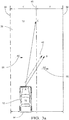
- Fig. 3b shows another embodiment where the controller is further configured to determine a last-vector 66, which is based on a temporal-history 68 ( Fig. 1 ) of the current-vector 56.
- the temporal-history 68 is defined as a series of data going back in time from the current data point.
- the last-vector 66 is stored in the memory 30 of the controller 28, thereby generating a data-buffer of the previous current-vector 56 data points.
- the last-vector 66 may be updated at a rate of between 1ms and 100ms.
- a predetermined number of the data points in the temporal-history 68 may be used to determine the last-vector 66 by known methods of data processing such as a running-average, an average of the ten most recent data points, an infinite-filter, and other methods known to one skilled in the art of data processing.
- the controller 28 is further configured to determine a correction-vector 62, illustrated by the arrow BC, based on the last-vector 66 and steer the vehicle 12 according to the correction-vector 62 until either the lane-marking 38 is detected by the camera 32, or until a time-threshold 64 has been reached where the vehicle-operation is returned to manual-mode 24.
- the correction-vector 62 is defined as the vehicle's 12 direction and vehicle's 12 speed needed to steer the vehicle 12 back to the desired point C, as previously determined by the controller 28.
- Fig. 4 illustrates a non-limiting example of a method 70 for controlling the vehicle 12.
- the method 70 is used in conjunction with the system 10 to steer a vehicle 12 in the automated-mode 14 and by the operator 16 in the manual-mode 24.
- Step 72 RECEIVE VIDEO-SIGNAL, may include receiving an image of a lane-marking 38 from a camera 32 suitable for use on the vehicle 12.
- the image 34 may include, but is not limited to, a lane-marking 38 on the left side and right side of a travel-lane of the roadway 36.
- the lane-marking 38 may include a solid-line, as is typically used to indicate the boundary of a travel-lane of the roadway 36.
- the lane-marking 38 may also include a dashed-line, as is also typically used to indicate the boundary of a travel-lane of the roadway 36.
- the lane-marking 38 may become non-existent or otherwise undetectable by the camera 32 for a number of reasons such as, but not limited to, fading of the lane-marking-paint, erosion of the road surface, snow or dirt on the roadway 36, precipitation or dirt on the lens of the camera 32, operational failure of the camera 32, etc.
- Examples of the camera 32 suitable for use on the vehicle 12 are commercially available as will be recognized by those skilled in the art, such as the APTINA MT9V023 from Micron Technology, Inc. of Boise, Idaho, USA.
- the camera 32 may be mounted on the front of the vehicle 12, or mounted in the interior of the vehicle 12 at a location suitable for the camera 32 to view the area around the vehicle 12 through the windshield of the vehicle 12.
- the camera 32 is preferably a video type camera or camera that can capture images of the roadway 36 and surrounding area at a sufficient frame-rate, of ten frames per second, for example.
- Step 74, RECEIVE POSITION-SIGNAL may include a signal from an inertial-measurement-unit (IMU) 40 used to determine the relative-motion 42 of the vehicle 12.
- the relative-motion 42 measured by the IMU 40 may include the vehicle's 12 current yaw rate, longitudinal and lateral acceleration, and pitch and roll rates.
- IMU 40 inertial-measurement-unit
- Step 75 RECEIVE SPEED-SIGNAL, may include a signal from a speed-sensor 52 used to determine the speed of the vehicle 12.
- the speed-sensor 52 may include a wheel-speed-sensor typically found on automotive applications.
- Other devices capable of determining the speed of the vehicle 12 may include, but are not limited to, a global positioning system (GPS) receiver, and a RADAR transmitter and receiver, and other devices as will be recognized by those skilled in the art.
- GPS global positioning system
- Step 76 DETECT LANE-MARKING, which may include detecting a lane-marking 38 of the roadway 36, by the controller 28, as captured by the camera 32.
- the controller 28 is configured (e.g. programmed or hardwired) to determine the centerline 48 on the roadway 36 for the vehicle 12 based on the lane-marking 38 of the roadway 36 detected by the camera 32. That is, the image 34 detected or captured by the camera 32 is processed by the controller 28 using known techniques for image-analysis 50 to determine where along the roadway 36 the vehicle should be operated or be steered. Vision processing technologies, such as the EYE Q® platform from Moblieye Vision Technologies, Ltd. of Jerusalem, Israel, or other suitable devices may be used.
- the centerline 48 is preferably in the middle of the lane-marking 38 of the roadway 36.
- Step 78 DETERMINE LAST-POSITION, may include determining a last-position 54 relative to the centerline 48 of a roadway 36 based on the lane-marking 38.
- the last-position 54 may be updated by the controller 28 based on a predetermined rate between one millisecond (1ms) and 100ms to account for changes in the curvature of the roadway 36 as the vehicle travels along the roadway 36.
- the update rate may be varied based on the speed of the vehicle 12.
- Step 80 DETERMINE CURRENT-VECTOR, may include determining a current-vector 56 which indicates the speed and direction of the vehicle 12 being steered by the controller 28 from point A to the desired point C ( Fig. 2 ).
- Step 81 DETERMINE LAST-VECTOR, which may include determining a last-vector based on the temporal-history 68 of the current-vector 56 stored in the memory 30 of the controller 28 thereby generating a data-buffer of the previous current-vector 56 data points.
- the last-vector 66 may be updated at a rate of between 1ms and 100ms.
- a predetermined number of the data points in the temporal-history 68 may be used to determine the last-vector 66 by known methods of data processing such as a running-average, an average of the ten most recent data points, an infinite-filter, and other methods known to one skilled in the art of data processing.
- Step 82 DETERMINE OFFSET-VECTOR, which may include determining an offset-vector 58 that indicates the actual motion of the vehicle 12 relative to the centerline 48 of the roadway 36, regardless of the desired value of the current-vector 56.
- the offset-vector 58 indicates the actual speed and actual direction of the vehicle 12 traveling from point A to point B ( Fig. 2 ).
- the offset-vector 58 may differ from the current-vector 56 due to crowning of the roadway 36, wind gusts, standing water, and other phenomena.
- Input from the IMU 40, the camera 32, and the speed-sensor 52 is used by the controller 28 to determine the offset-vector 58, as will be recognized by one skilled in the art.
- Step 84 may include steering the vehicle 12 in automated-mode 14 from point A at to a desired point C at the centerline 48 of the roadway 36, using the lane-marking 38 as detected by the camera 32.
- Step 86 DETERMINE OFFSET-POSITION, may include determining an offset-position 60 relative to the last-position 54 and based on the relative-motion 42 information received from the IMU 40 and the speed-sensor 52 when the lane-marking 38 is not detected by the camera 32.
- Step 88 DETERMINE CORRECTION-VECTOR, which may include determining a correction-vector 62, illustrated by the arrow BC ( Fig. 2b ), used to steer the vehicle 12 from the offset-position 60 to the desired point C at the centerline 48 of the roadway 36.
- the correction-vector 62 is based on the last-position 54 and the offset-vector 58, and is determined using the known method of vector algebra, where the correction-vector 62 is equal to the difference between the current-vector 56 and the offset-vector 58.
- the correction-vector 62 may be based on the last-vector 66 and the offset-vector 58.
- Step 90 DETERMINE IF TIME-THRESHOLD IS ACHIEVED, which may include determining if a time-threshold 64 is equal to a predefined time.
- the time-threshold 64 may vary according to the speed of the vehicle 12.
- Step 92 STEER VEHICLE BASED ON CORRECTION-VECTOR IN AUTOMATED-MODE, which may include steering the vehicle based on the correction-vector 62 in the automated-mode 14 when the time-threshold 64 has not been achieved.
- Step 94 STEER VEHICLE IN MANUAL-MODE, which may include steering the vehicle 12 in manual-mode 24 by the operator 16 when the time-threshold 64 has been achieved.
- a lane-keeping system (the system10), a controller 28 for the system 10 and a method 70 of controlling a vehicle 12 is provided.
- the system 10 described herein delays the disengagement of automated driving controls when lane-markings 38 are non-existent, or otherwise undetectable by the camera 32.
- the disengagement of automated driving controls even though the lane-markings are momentarily undetectable, can lead to significant customer dissatisfaction and annoyance.
Landscapes
- Engineering & Computer Science (AREA)
- Automation & Control Theory (AREA)
- Transportation (AREA)
- Mechanical Engineering (AREA)
- Physics & Mathematics (AREA)
- General Physics & Mathematics (AREA)
- Combustion & Propulsion (AREA)
- Chemical & Material Sciences (AREA)
- Human Computer Interaction (AREA)
- Electromagnetism (AREA)
- Aviation & Aerospace Engineering (AREA)
- Radar, Positioning & Navigation (AREA)
- Remote Sensing (AREA)
- Multimedia (AREA)
- Computer Vision & Pattern Recognition (AREA)
- Theoretical Computer Science (AREA)
- Traffic Control Systems (AREA)
- Control Of Driving Devices And Active Controlling Of Vehicle (AREA)
- Steering Control In Accordance With Driving Conditions (AREA)
Abstract
Description
- This disclosure generally relates to a lane-keeping system for an automated vehicle, and more particularly relates to using historical vehicle motion information to operate an automated vehicle when a lane-marking is not detected by a camera.
- It is known to operate, e.g. steer, an automated vehicle using a camera to detect features of a roadway such as lane-markings and curbs. However, in some instances those features may be inconsistent, degraded, or otherwise undetectable. In the absence of lane-markings, many systems simply disengage and give control back to the vehicle operator, even though lane-markings may be only momentarily undetected by the camera.
- In accordance with one embodiment, a lane-keeping system suitable for use on an automated vehicle is provided. The system includes a camera, an inertial-measurement-unit, and a controller. The camera is configured to detect a lane-marking of a roadway traveled by a vehicle. The inertial-measurement-unit is configured to determine relative-motion of the vehicle. The controller in communication with the camera and the inertial-measurement-unit. When the lane-marking is detected the controller is configured to: determine a last-position of the vehicle relative to the centerline of the roadway based on a the lane-marking, determine a current-vector used to steer the vehicle towards a centerline of the roadway based on the last-position, and determine an offset-vector indicative of motion of the vehicle relative to the centerline of the roadway. When the lane-marking is not detected the controller is configured to: determine an offset-position relative to the last-position based on information from the inertial-measurement-unit, determine a correction-vector used to steer the vehicle from the offset-position towards the centerline of the roadway based on the last-position and the offset-vector, and steer the vehicle according to the correction-vector.
- In another embodiment, a method for controlling an automated vehicle is provided. The method includes the step of receiving a video-signal from a camera. The method also includes the step of receiving a position-signal from an inertial-measurement-unit. The method also includes the step of detecting, by a controller, a lane-marking based on the video-signal. The method also includes the step of determining a last-position relative to a centerline of a roadway, based on the lane-marking. The method also includes the step of determining a current-vector based on the centerline of a roadway. The method also includes the step of determining an offset-vector, indicative of motion of the vehicle relative to the centerline, based on the position-signal. The method also includes the step of steering the vehicle according to the current-vector in an automated-mode when the lane marking is detected. The method also includes the step of determining an offset-position, relative to the last-position, based on the position-signal. The method also includes the step of determining a correction-vector, used to steer the vehicle from the offset-position towards the centerline of the roadway, based on the last-position and the offset-vector. The method also includes the step of steering the vehicle according to the correction-vector in an automated-mode when the lane-marking is not detected. The method also includes the step of steering the vehicle in a manual-mode, when the lane-marking is not detected, and after a time-threshold is achieved.
- Further features and advantages will appear more clearly on a reading of the following detailed description of the preferred embodiment, which is given by way of non-limiting example only and with reference to the accompanying drawings.
- The present invention will now be described, by way of example with reference to the accompanying drawings, in which:
-
Fig. 1 is a diagram of a lane-keeping system in accordance with one embodiment; -
Figs. 2a and2b are illustrations of motion on a roadway of a vehicle equipped with the system ofFig. 1 in accordance with one embodiment; -
Figs. 3a and3b are illustrations of motion on a roadway of a vehicle equipped with the system ofFig. 1 in accordance with one embodiment; and -
Fig. 4 is a flowchart of a method of operating the system ofFig. 1 in accordance with one embodiment. -
Fig. 1 illustrates a non-limiting example of a lane-keeping system 10, hereafter referred to as thesystem 10, suitable for use on an automated vehicle, hereafter referred to as thevehicle 12. In general, thesystem 10 is configured to operate (i.e. drive) thevehicle 12 in an automated-mode 14 whereby anoperator 16 of thevehicle 12 is little more than a passenger. That is, theoperator 16 is not substantively involved with thesteering 18 or operation of theaccelerator 20 andbrakes 22 of thevehicle 12. It is contemplated that thevehicle 12 may also be operated in a manual-mode 24 where theoperator 16 is fully responsible for operating the vehicle-controls 26, or in a partial-mode (not shown) where control of the vehicle is shared by theoperator 16 and a controller 28 of thesystem 10. - The controller 28 may include a processor (not specifically shown) such as a microprocessor or other control circuitry such as analog and/or digital control circuitry including an application specific integrated circuit (ASIC) for processing data as should be evident to those in the art. The controller 28 may include a
memory 30, including non-volatile memory, such as electrically erasable programmable read-only memory (EEPROM) for storing one or more routines, thresholds, and captured data. The one or more routines may be executed by the processor to perform steps for operating thevehicle 12 based on signals received by the controller 28 as described herein. - The
system 10 includes acamera 32 used to capture animage 34 of aroadway 36 traveled by thevehicle 12. Examples of thecamera 32 suitable for use on thevehicle 12 are commercially available as will be recognized by those in the art, one such being the APTINA MT9V023 from Micron Technology, Inc. of Boise, Idaho, USA. Thecamera 32 may be mounted on the front of thevehicle 12, or mounted in the interior of thevehicle 12 at a location suitable for thecamera 32 to view the area around thevehicle 12 through the windshield of thevehicle 12. Thecamera 32 is preferably a video type camera or camera that can capture images of theroadway 36 and surrounding area at a sufficient frame-rate, of ten frames per second, for example. - The
image 34 may include, but is not limited to, a lane-marking 38 on the left side and right side of a travel-lane of theroadway 36. The lane-marking 38 may include a solid-line, as is typically used to indicate the boundary of a travel-lane of theroadway 36. The lane-marking 38 may also include a dashed-line, as is also typically used to indicate the boundary of a travel-lane of theroadway 36. The lane-marking 38 may become non-existent or otherwise undetectable by thecamera 32 for a number of reasons such as, but not limited to, fading of the lane-marking-paint, erosion of the road surface, snow or dirt on theroadway 36, precipitation or dirt on the lens of thecamera 32, operational failure of thecamera 32, etc. - The
system 10 also includes an inertial-measurement-unit 40, hereafter referred to as the IMU 40, used to determine a relative-motion 42 of thevehicle 12. The relative-motion 42 measured by theIMU 40 may include the vehicle's 12 current yaw rate, longitudinal acceleration, lateral acceleration, pitch rate, and roll rate. One example of the several instances of the IMU 40 suitable for use on thevehicle 12 that are commercially available as will be recognized by those in the art, is the 6DF-1N6-C2-HWL from Honeywell Sensing and Control, Golden Valley, Minnesota, USA. - The
system 10 may also include a speed-sensor 52 used to determine a speed of thevehicle 12. The speed-sensor 52 may include a wheel-speed-sensor typically found on automotive applications. Other sensors capable of determining the speed of thevehicle 12 may include, but are not limited to, a global positioning system (GPS) receiver, and a RADAR transceiver, and other devices as will be recognized by those skilled in the art. - The controller is in electrical communication with the
camera 32 and the IMU 40 so that the controller 28 can receive theimage 34, via a video-signal 44, and the relative-motion 42 of thevehicle 12, via a position-signal 46. The position-signal 46 originates in theIMU 40 and may include the vehicle's 12 current yaw rate, longitudinal acceleration, lateral acceleration, pitch rate, and roll rate, which defines the relative-motion 42 of thevehicle 12, e.g. lateral-motion, longitudinal-motion, change in yaw-angle, etc. of thevehicle 12. The controller 28 is also in electrical communication with the speed-sensor 52 so that the controller 28 can receive an speed of thevehicle 12 via a speed-signal 53. - The controller 28 is generally configured (e.g. programmed or hardwired) to determine a
centerline 48 on theroadway 36 for thevehicle 12 based on the lane-marking 38 of theroadway 36 detected by thecamera 32. That is, theimage 34 detected or captured by thecamera 32 is processed by the controller 28 using known techniques for image-analysis 50 to determine where along theroadway 36 the vehicle should be operated or be steered. Vision processing technologies, such as the EYE Q® platform from Moblieye Vision Technologies, Ltd. of Jerusalem, Israel, or other suitable devices may be used. By way of example and not limitation, thecenterline 48 is preferably in the middle of the travel-lane defined by the lane-marking 38 of theroadway 36. -
Fig. 2a illustrates a non-limiting example of when the controller 28 is steering thevehicle 12 in the automated-mode 14 from point A at time T0 towards a desired point C located at thecenterline 48 of theroadway 36. The controller 28 is using the lane-marking 38 as detected by thecamera 32 to determine thecenterline 48. Point C is located at a predetermined line-of-sight distance in front of thevehicle 12, as will be recognized by one skilled on the art of automated vehicle controls, and represents the desired position of thevehicle 12 at time T2, which is understood to be in the future relative to time T0. The controller 28 is further configured to determine a last-position 54 relative to thecenterline 48 of theroadway 36 based on the lane-marking 38. The last-position 54 may be updated by the controller 28 based on a predetermined rate, between one millisecond (1ms) and 100ms for example, to account for changes in the curvature of theroadway 36 as the vehicle travels along theroadway 36. The update rate may be varied based on the speed of thevehicle 12. When the lane-marking 38 is detected by thecamera 32, the last-position 54 and point A coincide or are coincident. By way of example and not limitation, the last-position 54 is shown to be located to the left of thecenterline 48 of theroadway 36 at time T0 inFig. 2 . The controller 28 is further configured to determine a current-vector 56, represented by the arrow labeled AC, which illustrates the speed and direction of thevehicle 12 being steered by the controller 28 from point A to the desired point C. The controller is further configured to determine an offset-vector 58 that indicates the actual motion of thevehicle 12 relative to thecenterline 48 and/or the lane-marking 38 of theroadway 36, regardless of the desired value of the current-vector 56. The offset-vector 58 is represented by the arrow labeled AB, which illustrates the actual speed and actual direction of thevehicle 12 traveling from point A to point B. The offset-vector 58 may differ from the current-vector 56 due to crowning of theroadway 36, wind gusts, standing water, and other phenomena. Input from theIMU 40, thecamera 32, and the speed-sensor 52 is used by the controller 28 to determine the offset-vector 58, as will be recognized by one skilled in the art. -
Fig. 2b shows a non-limiting example for when the lane-marking 38 is not detected by thecamera 32, as illustrated in the figure by the discontinuity or termination of the lane-marking 38 after point A. The discontinuity of the lane-marking 38 may occur on either side, or both sides, of theroadway 36. At time T1, thevehicle 12 has moved from the last-position 54 to point B and the controller has determined the offset-vector 58 as described previously. The controller 28 is further configured to determine an offset-position 60 relative to the last-position 54, and based on the relative-motion 42 information received from theIMU 40 and based on the speed of thevehicle 12 received from the speed-sensor 52. The offset-position 60 is defined as the position attained by thevehicle 12 that is off the desired path of travel, or in other words, how far thevehicle 12 is off-course from the current-vector 56. The controller 28 is further configured to determine a correction-vector 62, illustrated by the arrow BC, used to steer thevehicle 12 from the offset-position 60 to the desired point C. The correction-vector 62 is defined as the vehicle's 12 direction and vehicle's 12 speed needed to steer thevehicle 12 back to the desired point C, as previously determined by the controller 28. The correction-vector 62 is based on the last-position 54 and the offset-vector 58, and is determined using the known method of vector algebra, where the correction-vector 62 is equal to the difference between the current-vector 56 and the offset-vector 58. The controller 28 then steers thevehicle 12 according to the correction-vector 62 until either the lane-marking 38 is detected by thecamera 32, or until a time-threshold 64 (Fig. 1 ) has been reached where the vehicle-operation is returned to manual-mode 24. The time-threshold 64 may vary according to the speed of thevehicle 12. -
Fig. 3b shows another embodiment where the controller is further configured to determine a last-vector 66, which is based on a temporal-history 68 (Fig. 1 ) of the current-vector 56. The temporal-history 68 is defined as a series of data going back in time from the current data point. The last-vector 66 is stored in thememory 30 of the controller 28, thereby generating a data-buffer of the previous current-vector 56 data points. The last-vector 66 may be updated at a rate of between 1ms and 100ms. A predetermined number of the data points in the temporal-history 68 may be used to determine the last-vector 66 by known methods of data processing such as a running-average, an average of the ten most recent data points, an infinite-filter, and other methods known to one skilled in the art of data processing. The controller 28 is further configured to determine a correction-vector 62, illustrated by the arrow BC, based on the last-vector 66 and steer thevehicle 12 according to the correction-vector 62 until either the lane-marking 38 is detected by thecamera 32, or until a time-threshold 64 has been reached where the vehicle-operation is returned to manual-mode 24. The correction-vector 62 is defined as the vehicle's 12 direction and vehicle's 12 speed needed to steer thevehicle 12 back to the desired point C, as previously determined by the controller 28. -
Fig. 4 illustrates a non-limiting example of amethod 70 for controlling thevehicle 12. In particular, themethod 70 is used in conjunction with thesystem 10 to steer avehicle 12 in the automated-mode 14 and by theoperator 16 in the manual-mode 24. -
Step 72, RECEIVE VIDEO-SIGNAL, may include receiving an image of a lane-marking 38 from acamera 32 suitable for use on thevehicle 12. Theimage 34 may include, but is not limited to, a lane-marking 38 on the left side and right side of a travel-lane of theroadway 36. The lane-marking 38 may include a solid-line, as is typically used to indicate the boundary of a travel-lane of theroadway 36. The lane-marking 38 may also include a dashed-line, as is also typically used to indicate the boundary of a travel-lane of theroadway 36. The lane-marking 38 may become non-existent or otherwise undetectable by thecamera 32 for a number of reasons such as, but not limited to, fading of the lane-marking-paint, erosion of the road surface, snow or dirt on theroadway 36, precipitation or dirt on the lens of thecamera 32, operational failure of thecamera 32, etc. Examples of thecamera 32 suitable for use on thevehicle 12 are commercially available as will be recognized by those skilled in the art, such as the APTINA MT9V023 from Micron Technology, Inc. of Boise, Idaho, USA. Thecamera 32 may be mounted on the front of thevehicle 12, or mounted in the interior of thevehicle 12 at a location suitable for thecamera 32 to view the area around thevehicle 12 through the windshield of thevehicle 12. Thecamera 32 is preferably a video type camera or camera that can capture images of theroadway 36 and surrounding area at a sufficient frame-rate, of ten frames per second, for example. -
Step 74, RECEIVE POSITION-SIGNAL, may include a signal from an inertial-measurement-unit (IMU) 40 used to determine the relative-motion 42 of thevehicle 12. The relative-motion 42 measured by theIMU 40 may include the vehicle's 12 current yaw rate, longitudinal and lateral acceleration, and pitch and roll rates. One example of the several instances of theIMU 40 suitable for use on thevehicle 12 that are commercially available as will be recognized by those in the art, is the 6DF-1N6-C2-HWL from Honeywell Sensing and Control, Golden Valley, Minnesota, USA. -
Step 75, RECEIVE SPEED-SIGNAL, may include a signal from a speed-sensor 52 used to determine the speed of thevehicle 12. The speed-sensor 52 may include a wheel-speed-sensor typically found on automotive applications. Other devices capable of determining the speed of thevehicle 12 may include, but are not limited to, a global positioning system (GPS) receiver, and a RADAR transmitter and receiver, and other devices as will be recognized by those skilled in the art. -
Step 76, DETECT LANE-MARKING, which may include detecting a lane-marking 38 of theroadway 36, by the controller 28, as captured by thecamera 32. The controller 28 is configured (e.g. programmed or hardwired) to determine thecenterline 48 on theroadway 36 for thevehicle 12 based on the lane-marking 38 of theroadway 36 detected by thecamera 32. That is, theimage 34 detected or captured by thecamera 32 is processed by the controller 28 using known techniques for image-analysis 50 to determine where along theroadway 36 the vehicle should be operated or be steered. Vision processing technologies, such as the EYE Q® platform from Moblieye Vision Technologies, Ltd. of Jerusalem, Israel, or other suitable devices may be used. Typically, thecenterline 48 is preferably in the middle of the lane-marking 38 of theroadway 36. -
Step 78, DETERMINE LAST-POSITION, may include determining a last-position 54 relative to thecenterline 48 of aroadway 36 based on the lane-marking 38. The last-position 54 may be updated by the controller 28 based on a predetermined rate between one millisecond (1ms) and 100ms to account for changes in the curvature of theroadway 36 as the vehicle travels along theroadway 36. The update rate may be varied based on the speed of thevehicle 12. -
Step 80, DETERMINE CURRENT-VECTOR, may include determining a current-vector 56 which indicates the speed and direction of thevehicle 12 being steered by the controller 28 from point A to the desired point C (Fig. 2 ). -
Step 81, DETERMINE LAST-VECTOR, which may include determining a last-vector based on the temporal-history 68 of the current-vector 56 stored in thememory 30 of the controller 28 thereby generating a data-buffer of the previous current-vector 56 data points. The last-vector 66 may be updated at a rate of between 1ms and 100ms. A predetermined number of the data points in the temporal-history 68 may be used to determine the last-vector 66 by known methods of data processing such as a running-average, an average of the ten most recent data points, an infinite-filter, and other methods known to one skilled in the art of data processing. -
Step 82, DETERMINE OFFSET-VECTOR, which may include determining an offset-vector 58 that indicates the actual motion of thevehicle 12 relative to thecenterline 48 of theroadway 36, regardless of the desired value of the current-vector 56. The offset-vector 58 indicates the actual speed and actual direction of thevehicle 12 traveling from point A to point B (Fig. 2 ). The offset-vector 58 may differ from the current-vector 56 due to crowning of theroadway 36, wind gusts, standing water, and other phenomena. Input from theIMU 40, thecamera 32, and the speed-sensor 52 is used by the controller 28 to determine the offset-vector 58, as will be recognized by one skilled in the art. -
Step 84, STEER VEHICLE BASED ON CURRENT-VECTOR IN AUTOMATED-MODE, may include steering thevehicle 12 in automated-mode 14 from point A at to a desired point C at thecenterline 48 of theroadway 36, using the lane-marking 38 as detected by thecamera 32. -
Step 86, DETERMINE OFFSET-POSITION, may include determining an offset-position 60 relative to the last-position 54 and based on the relative-motion 42 information received from theIMU 40 and the speed-sensor 52 when the lane-marking 38 is not detected by thecamera 32. -
Step 88, DETERMINE CORRECTION-VECTOR, which may include determining a correction-vector 62, illustrated by the arrow BC (Fig. 2b ), used to steer thevehicle 12 from the offset-position 60 to the desired point C at thecenterline 48 of theroadway 36. The correction-vector 62 is based on the last-position 54 and the offset-vector 58, and is determined using the known method of vector algebra, where the correction-vector 62 is equal to the difference between the current-vector 56 and the offset-vector 58. Alternatively, the correction-vector 62 may be based on the last-vector 66 and the offset-vector 58. -
Step 90, DETERMINE IF TIME-THRESHOLD IS ACHIEVED, which may include determining if a time-threshold 64 is equal to a predefined time. The time-threshold 64 may vary according to the speed of thevehicle 12. -
Step 92, STEER VEHICLE BASED ON CORRECTION-VECTOR IN AUTOMATED-MODE, which may include steering the vehicle based on the correction-vector 62 in the automated-mode 14 when the time-threshold 64 has not been achieved. -
Step 94, STEER VEHICLE IN MANUAL-MODE, which may include steering thevehicle 12 in manual-mode 24 by theoperator 16 when the time-threshold 64 has been achieved. - Accordingly, a lane-keeping system (the system10), a controller 28 for the
system 10 and amethod 70 of controlling avehicle 12 is provided. In contrast to prior systems, thesystem 10 described herein delays the disengagement of automated driving controls when lane-markings 38 are non-existent, or otherwise undetectable by thecamera 32. The disengagement of automated driving controls, even though the lane-markings are momentarily undetectable, can lead to significant customer dissatisfaction and annoyance. - While this invention has been described in terms of the preferred embodiments thereof, it is not intended to be so limited, but rather only to the extent set forth in the claims that follow.
Claims (7)
- A lane-keeping system (10) suitable for use on an automated vehicle (12), said system (10) comprising:a camera (32) configured to detect a lane-marking (38) of a roadway (36) traveled by a vehicle (12);an inertial-measurement-unit (40) configured to determine relative-motion (42) of the vehicle (12); anda controller (28) in communication with the camera (32) and the inertial-measurement-unit (40), wherein when the lane-marking (38) is detected said controller (28) is configured todetermine a last-position (54) of the vehicle (12) relative to a centerline (48) of the roadway (36) based on a the lane-marking (38),determine a current-vector (56) used to steer the vehicle (12) towards the centerline (48) of the roadway (36) based on the last-position (54), anddetermine an offset-vector (58) indicative of motion of the vehicle (12) relative to the centerline (48) of the roadway (36), and whereinwhen the lane-marking (38) is not detected said controller (28) is configured todetermine an offset-position (60) relative to the last-position (54) based on information from the inertial-measurement-unit (40),determine a correction-vector (62) used to steer the vehicle (12) from the offset-position (60) towards the centerline (48) of the roadway (36) based on the last-position (54) and the offset-vector (58), andsteer the vehicle (12) according to the correction-vector (62).
- The system (10) in accordance with claim 1, wherein the controller (28) is further configured to determine a last-vector (66) based on a temporal-history (68) of the current-vector (56), and the correction-vector (62) is further based on the last-vector (66).
- The system (10) in accordance with claim 1 or 2, wherein the system (10) includes a speed-sensor (52) configured to measure speed of the vehicle (12), and the offset-position (60) is also determined based on the speed.
- A method (70) for controlling an automated vehicle (12), said method (70) comprising:receiving (72) a video-signal (44) from a camera (32);receiving (74) a position-signal (46) from an inertial-measurement-unit (40);detecting (76), by a controller (28), a lane-marking (38) based on the video-signal (44);determining (78) a last-position (54) relative to a centerline (48) of a roadway (36) based on the lane-marking (38);determining (80) a current-vector (56) based on the centerline (48) of the roadway (36);determining (82) an offset-vector (58) indicative of motion of the vehicle (12) relative to the centerline (48) based on the position-signal (46);steering (84) the vehicle (12) according to the current-vector (56) in an automated-mode (14) when the lane-marking (38) is detected;determining (86) an offset-position (60) relative to the last-position (54) based on the position-signal (46);determining (88) a correction-vector (62) used to steer the vehicle (12) from the offset-position (60) towards the centerline (48) of the roadway (36) based on the last-position (54) and the offset-vector (58);steering (92) the vehicle (12) according to the correction-vector (62) in an automated-mode (14) when the lane-marking (38) is not detected; andsteering (94) the vehicle (12) in a manual-mode (24) when the lane-marking (38) is not detected and after a time-threshold (64) is achieved.
- The method (70) in accordance with claim 4, wherein the method (70) includes the step of receiving (75) a speed-signal (53) from a speed-sensor (52), and the step of determining (82) the offset-vector (58) is further based on a speed of the vehicle (12).
- The method (70) in accordance with claim 4 or 5, wherein the method (70) includes determining (81) a last-vector (66) based on a temporal-history (68) of the current-vector (56), and the correction-vector (62) is further based on the last-vector (66).
- The method (70) in accordance with claim 6, wherein the last-vector (66) is a running-average of the last-vector (66) data points stored in a memory (30) of the controller (28).
Applications Claiming Priority (1)
| Application Number | Priority Date | Filing Date | Title |
|---|---|---|---|
| US15/154,076 US10019014B2 (en) | 2016-05-13 | 2016-05-13 | Lane-keeping system for automated vehicles |
Publications (2)
| Publication Number | Publication Date |
|---|---|
| EP3243729A1 true EP3243729A1 (en) | 2017-11-15 |
| EP3243729B1 EP3243729B1 (en) | 2019-01-02 |
Family
ID=58709790
Family Applications (1)
| Application Number | Title | Priority Date | Filing Date |
|---|---|---|---|
| EP17170164.2A Active EP3243729B1 (en) | 2016-05-13 | 2017-05-09 | Lane-keeping system for automated vehicles |
Country Status (3)
| Country | Link |
|---|---|
| US (1) | US10019014B2 (en) |
| EP (1) | EP3243729B1 (en) |
| CN (1) | CN107364443B (en) |
Cited By (3)
| Publication number | Priority date | Publication date | Assignee | Title |
|---|---|---|---|---|
| EP3835908A4 (en) * | 2018-12-13 | 2022-01-19 | Huawei Technologies Co., Ltd. | AUTONOMOUS DRIVING METHOD, LEARNING METHOD AND ASSOCIATED APPARATUS |
| FR3114787A1 (en) * | 2020-10-07 | 2022-04-08 | Psa Automobiles Sa | Method and device for autonomous driving of a vehicle in order to keep the vehicle in the center of a traffic lane. |
| CN110239518B (en) * | 2019-05-20 | 2023-09-01 | 福瑞泰克智能系统有限公司 | Vehicle transverse position control method and device |
Families Citing this family (14)
| Publication number | Priority date | Publication date | Assignee | Title |
|---|---|---|---|---|
| US20180259961A1 (en) * | 2017-03-07 | 2018-09-13 | Delphi Technologies, Inc. | Lane-changing system for automated vehicles |
| US10529080B2 (en) * | 2017-06-23 | 2020-01-07 | Satori Worldwide, Llc | Automatic thoroughfare recognition and traffic counting |
| CN110562251A (en) * | 2018-06-05 | 2019-12-13 | 广州小鹏汽车科技有限公司 | A method and device for automatic driving |
| DE102018218835B4 (en) * | 2018-11-05 | 2025-11-13 | Hyundai Motor Company | Methods for at least partially unblocking a motor vehicle's field of vision, especially during lane changes |
| US10703365B1 (en) * | 2018-12-26 | 2020-07-07 | Automotive Research & Testing Center | Lane tracking method and lane tracking system for an autonomous vehicle |
| US11009881B2 (en) | 2019-04-05 | 2021-05-18 | Caterpillar Paving Products Inc. | Roadway center detection for autonomous vehicle control |
| US11514594B2 (en) | 2019-10-30 | 2022-11-29 | Vergence Automation, Inc. | Composite imaging systems using a focal plane array with in-pixel analog storage elements |
| CN111516673B (en) * | 2020-04-30 | 2022-08-09 | 重庆长安汽车股份有限公司 | Lane line fusion system and method based on intelligent camera and high-precision map positioning |
| US12230649B2 (en) | 2020-05-19 | 2025-02-18 | Vergence Automation, Inc. | AI system on chip (SOC) for robotics vision applications |
| JP2022125932A (en) * | 2021-02-17 | 2022-08-29 | 本田技研工業株式会社 | Yaw rate estimation device |
| US20220371585A1 (en) * | 2021-05-21 | 2022-11-24 | Robert Bosch Gmbh | Customizable lane biasing for an automated vehicle |
| DE102021002728A1 (en) * | 2021-05-26 | 2022-12-01 | Bomag Gmbh | METHOD OF CONTROLLING THE TRAVEL OPERATION OF A SELF-PROPELLED SOIL COMPACTION MACHINE AND SOIL COMPACTION MACHINE |
| US20240025400A1 (en) * | 2022-07-20 | 2024-01-25 | Ford Global Technologies, Llc | Far infrared detection of compacted snow for lane keeping |
| US12509074B2 (en) | 2023-03-23 | 2025-12-30 | Torc Robotics, Inc. | Systems and methods for high precision lane-keeping by autonomous vehicles |
Citations (2)
| Publication number | Priority date | Publication date | Assignee | Title |
|---|---|---|---|---|
| EP2333484A1 (en) * | 2008-09-25 | 2011-06-15 | Clarion Co., Ltd. | Lane determining device and navigation system |
| US8996197B2 (en) * | 2013-06-20 | 2015-03-31 | Ford Global Technologies, Llc | Lane monitoring with electronic horizon |
Family Cites Families (9)
| Publication number | Priority date | Publication date | Assignee | Title |
|---|---|---|---|---|
| DE102005024382A1 (en) * | 2005-05-27 | 2006-12-07 | Robert Bosch Gmbh | Lane departure warning for motor vehicles |
| US8392064B2 (en) * | 2008-05-27 | 2013-03-05 | The Board Of Trustees Of The Leland Stanford Junior University | Systems, methods and devices for adaptive steering control of automotive vehicles |
| CN102348592B (en) * | 2009-04-21 | 2014-08-06 | 丰田自动车株式会社 | Driving assistance apparatus |
| JP5594246B2 (en) * | 2011-07-20 | 2014-09-24 | 株式会社デンソー | Lane recognition device |
| US9139203B2 (en) * | 2011-11-04 | 2015-09-22 | GM Global Technology Operations LLC | Lane tracking system |
| KR101502510B1 (en) * | 2013-11-26 | 2015-03-13 | 현대모비스 주식회사 | Apparatus and method for controlling lane keeping of vehicle |
| KR101502511B1 (en) * | 2013-11-28 | 2015-03-13 | 현대모비스 주식회사 | Apparatus and method for generating virtual lane, and system for controlling lane keeping of vehicle with the said apparatus |
| JP6217412B2 (en) * | 2014-01-29 | 2017-10-25 | アイシン・エィ・ダブリュ株式会社 | Automatic driving support device, automatic driving support method and program |
| JP5991340B2 (en) * | 2014-04-28 | 2016-09-14 | トヨタ自動車株式会社 | Driving assistance device |
-
2016
- 2016-05-13 US US15/154,076 patent/US10019014B2/en active Active
-
2017
- 2017-05-09 EP EP17170164.2A patent/EP3243729B1/en active Active
- 2017-05-12 CN CN201710334229.2A patent/CN107364443B/en active Active
Patent Citations (2)
| Publication number | Priority date | Publication date | Assignee | Title |
|---|---|---|---|---|
| EP2333484A1 (en) * | 2008-09-25 | 2011-06-15 | Clarion Co., Ltd. | Lane determining device and navigation system |
| US8996197B2 (en) * | 2013-06-20 | 2015-03-31 | Ford Global Technologies, Llc | Lane monitoring with electronic horizon |
Cited By (4)
| Publication number | Priority date | Publication date | Assignee | Title |
|---|---|---|---|---|
| EP3835908A4 (en) * | 2018-12-13 | 2022-01-19 | Huawei Technologies Co., Ltd. | AUTONOMOUS DRIVING METHOD, LEARNING METHOD AND ASSOCIATED APPARATUS |
| CN110239518B (en) * | 2019-05-20 | 2023-09-01 | 福瑞泰克智能系统有限公司 | Vehicle transverse position control method and device |
| FR3114787A1 (en) * | 2020-10-07 | 2022-04-08 | Psa Automobiles Sa | Method and device for autonomous driving of a vehicle in order to keep the vehicle in the center of a traffic lane. |
| WO2022074307A1 (en) * | 2020-10-07 | 2022-04-14 | Psa Automobiles Sa | Method and device for autonomous driving of a vehicle in order to keep the vehicle at the centre of a traffic lane |
Also Published As
| Publication number | Publication date |
|---|---|
| CN107364443B (en) | 2019-09-10 |
| US10019014B2 (en) | 2018-07-10 |
| EP3243729B1 (en) | 2019-01-02 |
| CN107364443A (en) | 2017-11-21 |
| US20170329345A1 (en) | 2017-11-16 |
Similar Documents
| Publication | Publication Date | Title |
|---|---|---|
| EP3243729B1 (en) | Lane-keeping system for automated vehicles | |
| US11745659B2 (en) | Vehicular system for controlling vehicle | |
| US11377029B2 (en) | Vehicular trailering assist system with trailer state estimation | |
| EP3373094A1 (en) | Lane-changing system for automated vehicles | |
| US11312353B2 (en) | Vehicular control system with vehicle trajectory tracking | |
| EP2251238B1 (en) | Vehicle travel support device, vehicle, and vehicle travel support program | |
| CN107792068B (en) | Automated Vehicle Lane Change Control System | |
| US11093761B2 (en) | Lane position sensing and tracking in a vehicle | |
| EP3336582B1 (en) | Vision sensing compensation | |
| US10967864B2 (en) | Vehicle control device | |
| EP3190022B1 (en) | Lane extension for vision steered automated vehicle | |
| JP6941178B2 (en) | Automatic operation control device and method | |
| US12337827B2 (en) | Method for training a trajectory for a vehicle, and electronic vehicle guidance system | |
| US12194992B2 (en) | Vehicular automatic emergency braking system with cross-path threat determination | |
| WO2018172460A1 (en) | Driver assistance system for a vehicle for predicting a lane area ahead of the vehicle, vehicle and method | |
| EP4194298A1 (en) | Vehicle control device, vehicle control method, and vehicle control system | |
| JP2022154933A (en) | Vehicle control device, computer program for vehicle control and vehicle control method | |
| CN114987507A (en) | Method, device and storage medium for determining the spatial orientation of a trailer | |
| KR102660192B1 (en) | Lane Departure Prevention Apparatus | |
| US20190082096A1 (en) | Vehicle camera system | |
| EP4448360A1 (en) | Method for operating a vehicle, computer program product, control system and vehicle | |
| CN119261760A (en) | Lane display device and method thereof | |
| JP2008308100A (en) | Braking force controlling device |
Legal Events
| Date | Code | Title | Description |
|---|---|---|---|
| PUAI | Public reference made under article 153(3) epc to a published international application that has entered the european phase |
Free format text: ORIGINAL CODE: 0009012 |
|
| STAA | Information on the status of an ep patent application or granted ep patent |
Free format text: STATUS: THE APPLICATION HAS BEEN PUBLISHED |
|
| AK | Designated contracting states |
Kind code of ref document: A1 Designated state(s): AL AT BE BG CH CY CZ DE DK EE ES FI FR GB GR HR HU IE IS IT LI LT LU LV MC MK MT NL NO PL PT RO RS SE SI SK SM TR |
|
| AX | Request for extension of the european patent |
Extension state: BA ME |
|
| STAA | Information on the status of an ep patent application or granted ep patent |
Free format text: STATUS: REQUEST FOR EXAMINATION WAS MADE |
|
| 17P | Request for examination filed |
Effective date: 20180515 |
|
| RBV | Designated contracting states (corrected) |
Designated state(s): AL AT BE BG CH CY CZ DE DK EE ES FI FR GB GR HR HU IE IS IT LI LT LU LV MC MK MT NL NO PL PT RO RS SE SI SK SM TR |
|
| GRAP | Despatch of communication of intention to grant a patent |
Free format text: ORIGINAL CODE: EPIDOSNIGR1 |
|
| STAA | Information on the status of an ep patent application or granted ep patent |
Free format text: STATUS: GRANT OF PATENT IS INTENDED |
|
| RIC1 | Information provided on ipc code assigned before grant |
Ipc: G05D 1/02 20060101ALI20180605BHEP Ipc: B62D 15/02 20060101AFI20180605BHEP Ipc: G08G 1/16 20060101ALI20180605BHEP Ipc: G06K 9/00 20060101ALI20180605BHEP Ipc: B60W 30/12 20060101ALI20180605BHEP Ipc: B60W 10/20 20060101ALI20180605BHEP Ipc: B60W 30/10 20060101ALI20180605BHEP |
|
| INTG | Intention to grant announced |
Effective date: 20180702 |
|
| GRAS | Grant fee paid |
Free format text: ORIGINAL CODE: EPIDOSNIGR3 |
|
| GRAA | (expected) grant |
Free format text: ORIGINAL CODE: 0009210 |
|
| STAA | Information on the status of an ep patent application or granted ep patent |
Free format text: STATUS: THE PATENT HAS BEEN GRANTED |
|
| RAP1 | Party data changed (applicant data changed or rights of an application transferred) |
Owner name: APTIV TECHNOLOGIES LIMITED |
|
| AK | Designated contracting states |
Kind code of ref document: B1 Designated state(s): AL AT BE BG CH CY CZ DE DK EE ES FI FR GB GR HR HU IE IS IT LI LT LU LV MC MK MT NL NO PL PT RO RS SE SI SK SM TR |
|
| REG | Reference to a national code |
Ref country code: GB Ref legal event code: FG4D |
|
| REG | Reference to a national code |
Ref country code: CH Ref legal event code: EP Ref country code: AT Ref legal event code: REF Ref document number: 1083984 Country of ref document: AT Kind code of ref document: T Effective date: 20190115 |
|
| REG | Reference to a national code |
Ref country code: IE Ref legal event code: FG4D |
|
| REG | Reference to a national code |
Ref country code: DE Ref legal event code: R096 Ref document number: 602017001646 Country of ref document: DE |
|
| REG | Reference to a national code |
Ref country code: NL Ref legal event code: MP Effective date: 20190102 |
|
| REG | Reference to a national code |
Ref country code: LT Ref legal event code: MG4D |
|
| REG | Reference to a national code |
Ref country code: AT Ref legal event code: MK05 Ref document number: 1083984 Country of ref document: AT Kind code of ref document: T Effective date: 20190102 |
|
| PG25 | Lapsed in a contracting state [announced via postgrant information from national office to epo] |
Ref country code: NL Free format text: LAPSE BECAUSE OF FAILURE TO SUBMIT A TRANSLATION OF THE DESCRIPTION OR TO PAY THE FEE WITHIN THE PRESCRIBED TIME-LIMIT Effective date: 20190102 |
|
| PG25 | Lapsed in a contracting state [announced via postgrant information from national office to epo] |
Ref country code: ES Free format text: LAPSE BECAUSE OF FAILURE TO SUBMIT A TRANSLATION OF THE DESCRIPTION OR TO PAY THE FEE WITHIN THE PRESCRIBED TIME-LIMIT Effective date: 20190102 Ref country code: LT Free format text: LAPSE BECAUSE OF FAILURE TO SUBMIT A TRANSLATION OF THE DESCRIPTION OR TO PAY THE FEE WITHIN THE PRESCRIBED TIME-LIMIT Effective date: 20190102 Ref country code: FI Free format text: LAPSE BECAUSE OF FAILURE TO SUBMIT A TRANSLATION OF THE DESCRIPTION OR TO PAY THE FEE WITHIN THE PRESCRIBED TIME-LIMIT Effective date: 20190102 Ref country code: PL Free format text: LAPSE BECAUSE OF FAILURE TO SUBMIT A TRANSLATION OF THE DESCRIPTION OR TO PAY THE FEE WITHIN THE PRESCRIBED TIME-LIMIT Effective date: 20190102 Ref country code: NO Free format text: LAPSE BECAUSE OF FAILURE TO SUBMIT A TRANSLATION OF THE DESCRIPTION OR TO PAY THE FEE WITHIN THE PRESCRIBED TIME-LIMIT Effective date: 20190402 Ref country code: SE Free format text: LAPSE BECAUSE OF FAILURE TO SUBMIT A TRANSLATION OF THE DESCRIPTION OR TO PAY THE FEE WITHIN THE PRESCRIBED TIME-LIMIT Effective date: 20190102 Ref country code: PT Free format text: LAPSE BECAUSE OF FAILURE TO SUBMIT A TRANSLATION OF THE DESCRIPTION OR TO PAY THE FEE WITHIN THE PRESCRIBED TIME-LIMIT Effective date: 20190502 |
|
| PG25 | Lapsed in a contracting state [announced via postgrant information from national office to epo] |
Ref country code: IS Free format text: LAPSE BECAUSE OF FAILURE TO SUBMIT A TRANSLATION OF THE DESCRIPTION OR TO PAY THE FEE WITHIN THE PRESCRIBED TIME-LIMIT Effective date: 20190502 Ref country code: BG Free format text: LAPSE BECAUSE OF FAILURE TO SUBMIT A TRANSLATION OF THE DESCRIPTION OR TO PAY THE FEE WITHIN THE PRESCRIBED TIME-LIMIT Effective date: 20190402 Ref country code: GR Free format text: LAPSE BECAUSE OF FAILURE TO SUBMIT A TRANSLATION OF THE DESCRIPTION OR TO PAY THE FEE WITHIN THE PRESCRIBED TIME-LIMIT Effective date: 20190403 Ref country code: LV Free format text: LAPSE BECAUSE OF FAILURE TO SUBMIT A TRANSLATION OF THE DESCRIPTION OR TO PAY THE FEE WITHIN THE PRESCRIBED TIME-LIMIT Effective date: 20190102 Ref country code: RS Free format text: LAPSE BECAUSE OF FAILURE TO SUBMIT A TRANSLATION OF THE DESCRIPTION OR TO PAY THE FEE WITHIN THE PRESCRIBED TIME-LIMIT Effective date: 20190102 Ref country code: HR Free format text: LAPSE BECAUSE OF FAILURE TO SUBMIT A TRANSLATION OF THE DESCRIPTION OR TO PAY THE FEE WITHIN THE PRESCRIBED TIME-LIMIT Effective date: 20190102 |
|
| REG | Reference to a national code |
Ref country code: DE Ref legal event code: R097 Ref document number: 602017001646 Country of ref document: DE |
|
| PG25 | Lapsed in a contracting state [announced via postgrant information from national office to epo] |
Ref country code: CZ Free format text: LAPSE BECAUSE OF FAILURE TO SUBMIT A TRANSLATION OF THE DESCRIPTION OR TO PAY THE FEE WITHIN THE PRESCRIBED TIME-LIMIT Effective date: 20190102 Ref country code: RO Free format text: LAPSE BECAUSE OF FAILURE TO SUBMIT A TRANSLATION OF THE DESCRIPTION OR TO PAY THE FEE WITHIN THE PRESCRIBED TIME-LIMIT Effective date: 20190102 Ref country code: AL Free format text: LAPSE BECAUSE OF FAILURE TO SUBMIT A TRANSLATION OF THE DESCRIPTION OR TO PAY THE FEE WITHIN THE PRESCRIBED TIME-LIMIT Effective date: 20190102 Ref country code: SK Free format text: LAPSE BECAUSE OF FAILURE TO SUBMIT A TRANSLATION OF THE DESCRIPTION OR TO PAY THE FEE WITHIN THE PRESCRIBED TIME-LIMIT Effective date: 20190102 Ref country code: EE Free format text: LAPSE BECAUSE OF FAILURE TO SUBMIT A TRANSLATION OF THE DESCRIPTION OR TO PAY THE FEE WITHIN THE PRESCRIBED TIME-LIMIT Effective date: 20190102 Ref country code: AT Free format text: LAPSE BECAUSE OF FAILURE TO SUBMIT A TRANSLATION OF THE DESCRIPTION OR TO PAY THE FEE WITHIN THE PRESCRIBED TIME-LIMIT Effective date: 20190102 Ref country code: IT Free format text: LAPSE BECAUSE OF FAILURE TO SUBMIT A TRANSLATION OF THE DESCRIPTION OR TO PAY THE FEE WITHIN THE PRESCRIBED TIME-LIMIT Effective date: 20190102 Ref country code: DK Free format text: LAPSE BECAUSE OF FAILURE TO SUBMIT A TRANSLATION OF THE DESCRIPTION OR TO PAY THE FEE WITHIN THE PRESCRIBED TIME-LIMIT Effective date: 20190102 |
|
| PLBE | No opposition filed within time limit |
Free format text: ORIGINAL CODE: 0009261 |
|
| STAA | Information on the status of an ep patent application or granted ep patent |
Free format text: STATUS: NO OPPOSITION FILED WITHIN TIME LIMIT |
|
| PG25 | Lapsed in a contracting state [announced via postgrant information from national office to epo] |
Ref country code: SM Free format text: LAPSE BECAUSE OF FAILURE TO SUBMIT A TRANSLATION OF THE DESCRIPTION OR TO PAY THE FEE WITHIN THE PRESCRIBED TIME-LIMIT Effective date: 20190102 |
|
| 26N | No opposition filed |
Effective date: 20191003 |
|
| PG25 | Lapsed in a contracting state [announced via postgrant information from national office to epo] |
Ref country code: MC Free format text: LAPSE BECAUSE OF FAILURE TO SUBMIT A TRANSLATION OF THE DESCRIPTION OR TO PAY THE FEE WITHIN THE PRESCRIBED TIME-LIMIT Effective date: 20190102 |
|
| REG | Reference to a national code |
Ref country code: BE Ref legal event code: MM Effective date: 20190531 |
|
| PG25 | Lapsed in a contracting state [announced via postgrant information from national office to epo] |
Ref country code: SI Free format text: LAPSE BECAUSE OF FAILURE TO SUBMIT A TRANSLATION OF THE DESCRIPTION OR TO PAY THE FEE WITHIN THE PRESCRIBED TIME-LIMIT Effective date: 20190102 Ref country code: LU Free format text: LAPSE BECAUSE OF NON-PAYMENT OF DUE FEES Effective date: 20190509 |
|
| PG25 | Lapsed in a contracting state [announced via postgrant information from national office to epo] |
Ref country code: TR Free format text: LAPSE BECAUSE OF FAILURE TO SUBMIT A TRANSLATION OF THE DESCRIPTION OR TO PAY THE FEE WITHIN THE PRESCRIBED TIME-LIMIT Effective date: 20190102 |
|
| PG25 | Lapsed in a contracting state [announced via postgrant information from national office to epo] |
Ref country code: IE Free format text: LAPSE BECAUSE OF NON-PAYMENT OF DUE FEES Effective date: 20190509 |
|
| PG25 | Lapsed in a contracting state [announced via postgrant information from national office to epo] |
Ref country code: BE Free format text: LAPSE BECAUSE OF NON-PAYMENT OF DUE FEES Effective date: 20190531 |
|
| PG25 | Lapsed in a contracting state [announced via postgrant information from national office to epo] |
Ref country code: CH Free format text: LAPSE BECAUSE OF NON-PAYMENT OF DUE FEES Effective date: 20200531 Ref country code: LI Free format text: LAPSE BECAUSE OF NON-PAYMENT OF DUE FEES Effective date: 20200531 |
|
| PG25 | Lapsed in a contracting state [announced via postgrant information from national office to epo] |
Ref country code: CY Free format text: LAPSE BECAUSE OF FAILURE TO SUBMIT A TRANSLATION OF THE DESCRIPTION OR TO PAY THE FEE WITHIN THE PRESCRIBED TIME-LIMIT Effective date: 20190102 |
|
| PG25 | Lapsed in a contracting state [announced via postgrant information from national office to epo] |
Ref country code: MT Free format text: LAPSE BECAUSE OF FAILURE TO SUBMIT A TRANSLATION OF THE DESCRIPTION OR TO PAY THE FEE WITHIN THE PRESCRIBED TIME-LIMIT Effective date: 20190102 Ref country code: HU Free format text: LAPSE BECAUSE OF FAILURE TO SUBMIT A TRANSLATION OF THE DESCRIPTION OR TO PAY THE FEE WITHIN THE PRESCRIBED TIME-LIMIT; INVALID AB INITIO Effective date: 20170509 |
|
| PG25 | Lapsed in a contracting state [announced via postgrant information from national office to epo] |
Ref country code: MK Free format text: LAPSE BECAUSE OF FAILURE TO SUBMIT A TRANSLATION OF THE DESCRIPTION OR TO PAY THE FEE WITHIN THE PRESCRIBED TIME-LIMIT Effective date: 20190102 |
|
| P01 | Opt-out of the competence of the unified patent court (upc) registered |
Effective date: 20230420 |
|
| REG | Reference to a national code |
Ref country code: DE Ref legal event code: R081 Ref document number: 602017001646 Country of ref document: DE Owner name: APTIV TECHNOLOGIES AG, CH Free format text: FORMER OWNER: APTIV TECHNOLOGIES LTD., ST. MICHAEL, BB |
|
| PGFP | Annual fee paid to national office [announced via postgrant information from national office to epo] |
Ref country code: DE Payment date: 20250422 Year of fee payment: 9 |
|
| PGFP | Annual fee paid to national office [announced via postgrant information from national office to epo] |
Ref country code: FR Payment date: 20250404 Year of fee payment: 9 |
|
| PGFP | Annual fee paid to national office [announced via postgrant information from national office to epo] |
Ref country code: GB Payment date: 20260313 Year of fee payment: 10 |