EP3243684A1 - Vehicle occupant monitoring - Google Patents
Vehicle occupant monitoring Download PDFInfo
- Publication number
- EP3243684A1 EP3243684A1 EP16168971.6A EP16168971A EP3243684A1 EP 3243684 A1 EP3243684 A1 EP 3243684A1 EP 16168971 A EP16168971 A EP 16168971A EP 3243684 A1 EP3243684 A1 EP 3243684A1
- Authority
- EP
- European Patent Office
- Prior art keywords
- light
- control system
- vehicle
- electronic control
- vehicle occupant
- Prior art date
- Legal status (The legal status is an assumption and is not a legal conclusion. Google has not performed a legal analysis and makes no representation as to the accuracy of the status listed.)
- Withdrawn
Links
Images


Classifications
-
- B—PERFORMING OPERATIONS; TRANSPORTING
- B60—VEHICLES IN GENERAL
- B60K—ARRANGEMENT OR MOUNTING OF PROPULSION UNITS OR OF TRANSMISSIONS IN VEHICLES; ARRANGEMENT OR MOUNTING OF PLURAL DIVERSE PRIME-MOVERS IN VEHICLES; AUXILIARY DRIVES FOR VEHICLES; INSTRUMENTATION OR DASHBOARDS FOR VEHICLES; ARRANGEMENTS IN CONNECTION WITH COOLING, AIR INTAKE, GAS EXHAUST OR FUEL SUPPLY OF PROPULSION UNITS IN VEHICLES
- B60K35/00—Instruments specially adapted for vehicles; Arrangement of instruments in or on vehicles
- B60K35/20—Output arrangements, i.e. from vehicle to user, associated with vehicle functions or specially adapted therefor
- B60K35/28—Output arrangements, i.e. from vehicle to user, associated with vehicle functions or specially adapted therefor characterised by the type of the output information, e.g. video entertainment or vehicle dynamics information; characterised by the purpose of the output information, e.g. for attracting the attention of the driver
-
- B—PERFORMING OPERATIONS; TRANSPORTING
- B60—VEHICLES IN GENERAL
- B60K—ARRANGEMENT OR MOUNTING OF PROPULSION UNITS OR OF TRANSMISSIONS IN VEHICLES; ARRANGEMENT OR MOUNTING OF PLURAL DIVERSE PRIME-MOVERS IN VEHICLES; AUXILIARY DRIVES FOR VEHICLES; INSTRUMENTATION OR DASHBOARDS FOR VEHICLES; ARRANGEMENTS IN CONNECTION WITH COOLING, AIR INTAKE, GAS EXHAUST OR FUEL SUPPLY OF PROPULSION UNITS IN VEHICLES
- B60K28/00—Safety devices for propulsion-unit control, specially adapted for, or arranged in, vehicles, e.g. preventing fuel supply or ignition in the event of potentially dangerous conditions
- B60K28/02—Safety devices for propulsion-unit control, specially adapted for, or arranged in, vehicles, e.g. preventing fuel supply or ignition in the event of potentially dangerous conditions responsive to conditions relating to the driver
- B60K28/06—Safety devices for propulsion-unit control, specially adapted for, or arranged in, vehicles, e.g. preventing fuel supply or ignition in the event of potentially dangerous conditions responsive to conditions relating to the driver responsive to incapacity of driver
- B60K28/066—Safety devices for propulsion-unit control, specially adapted for, or arranged in, vehicles, e.g. preventing fuel supply or ignition in the event of potentially dangerous conditions responsive to conditions relating to the driver responsive to incapacity of driver actuating a signalling device
-
- B—PERFORMING OPERATIONS; TRANSPORTING
- B60—VEHICLES IN GENERAL
- B60K—ARRANGEMENT OR MOUNTING OF PROPULSION UNITS OR OF TRANSMISSIONS IN VEHICLES; ARRANGEMENT OR MOUNTING OF PLURAL DIVERSE PRIME-MOVERS IN VEHICLES; AUXILIARY DRIVES FOR VEHICLES; INSTRUMENTATION OR DASHBOARDS FOR VEHICLES; ARRANGEMENTS IN CONNECTION WITH COOLING, AIR INTAKE, GAS EXHAUST OR FUEL SUPPLY OF PROPULSION UNITS IN VEHICLES
- B60K35/00—Instruments specially adapted for vehicles; Arrangement of instruments in or on vehicles
- B60K35/10—Input arrangements, i.e. from user to vehicle, associated with vehicle functions or specially adapted therefor
-
- B—PERFORMING OPERATIONS; TRANSPORTING
- B60—VEHICLES IN GENERAL
- B60K—ARRANGEMENT OR MOUNTING OF PROPULSION UNITS OR OF TRANSMISSIONS IN VEHICLES; ARRANGEMENT OR MOUNTING OF PLURAL DIVERSE PRIME-MOVERS IN VEHICLES; AUXILIARY DRIVES FOR VEHICLES; INSTRUMENTATION OR DASHBOARDS FOR VEHICLES; ARRANGEMENTS IN CONNECTION WITH COOLING, AIR INTAKE, GAS EXHAUST OR FUEL SUPPLY OF PROPULSION UNITS IN VEHICLES
- B60K35/00—Instruments specially adapted for vehicles; Arrangement of instruments in or on vehicles
- B60K35/20—Output arrangements, i.e. from vehicle to user, associated with vehicle functions or specially adapted therefor
- B60K35/21—Output arrangements, i.e. from vehicle to user, associated with vehicle functions or specially adapted therefor using visual output, e.g. blinking lights or matrix displays
-
- B—PERFORMING OPERATIONS; TRANSPORTING
- B60—VEHICLES IN GENERAL
- B60W—CONJOINT CONTROL OF VEHICLE SUB-UNITS OF DIFFERENT TYPE OR DIFFERENT FUNCTION; CONTROL SYSTEMS SPECIALLY ADAPTED FOR HYBRID VEHICLES; ROAD VEHICLE DRIVE CONTROL SYSTEMS FOR PURPOSES NOT RELATED TO THE CONTROL OF A PARTICULAR SUB-UNIT
- B60W40/00—Estimation or calculation of non-directly measurable driving parameters for road vehicle drive control systems not related to the control of a particular sub unit, e.g. by using mathematical models
- B60W40/08—Estimation or calculation of non-directly measurable driving parameters for road vehicle drive control systems not related to the control of a particular sub unit, e.g. by using mathematical models related to drivers or passengers
-
- B—PERFORMING OPERATIONS; TRANSPORTING
- B60—VEHICLES IN GENERAL
- B60W—CONJOINT CONTROL OF VEHICLE SUB-UNITS OF DIFFERENT TYPE OR DIFFERENT FUNCTION; CONTROL SYSTEMS SPECIALLY ADAPTED FOR HYBRID VEHICLES; ROAD VEHICLE DRIVE CONTROL SYSTEMS FOR PURPOSES NOT RELATED TO THE CONTROL OF A PARTICULAR SUB-UNIT
- B60W50/00—Details of control systems for road vehicle drive control not related to the control of a particular sub-unit, e.g. process diagnostic or vehicle driver interfaces
- B60W50/08—Interaction between the driver and the control system
- B60W50/14—Means for informing the driver, warning the driver or prompting a driver intervention
-
- B—PERFORMING OPERATIONS; TRANSPORTING
- B60—VEHICLES IN GENERAL
- B60K—ARRANGEMENT OR MOUNTING OF PROPULSION UNITS OR OF TRANSMISSIONS IN VEHICLES; ARRANGEMENT OR MOUNTING OF PLURAL DIVERSE PRIME-MOVERS IN VEHICLES; AUXILIARY DRIVES FOR VEHICLES; INSTRUMENTATION OR DASHBOARDS FOR VEHICLES; ARRANGEMENTS IN CONNECTION WITH COOLING, AIR INTAKE, GAS EXHAUST OR FUEL SUPPLY OF PROPULSION UNITS IN VEHICLES
- B60K2360/00—Indexing scheme associated with groups B60K35/00 or B60K37/00 relating to details of instruments or dashboards
- B60K2360/16—Type of output information
- B60K2360/178—Warnings
-
- B—PERFORMING OPERATIONS; TRANSPORTING
- B60—VEHICLES IN GENERAL
- B60W—CONJOINT CONTROL OF VEHICLE SUB-UNITS OF DIFFERENT TYPE OR DIFFERENT FUNCTION; CONTROL SYSTEMS SPECIALLY ADAPTED FOR HYBRID VEHICLES; ROAD VEHICLE DRIVE CONTROL SYSTEMS FOR PURPOSES NOT RELATED TO THE CONTROL OF A PARTICULAR SUB-UNIT
- B60W40/00—Estimation or calculation of non-directly measurable driving parameters for road vehicle drive control systems not related to the control of a particular sub unit, e.g. by using mathematical models
- B60W40/08—Estimation or calculation of non-directly measurable driving parameters for road vehicle drive control systems not related to the control of a particular sub unit, e.g. by using mathematical models related to drivers or passengers
- B60W2040/0818—Inactivity or incapacity of driver
- B60W2040/0827—Inactivity or incapacity of driver due to sleepiness
-
- B—PERFORMING OPERATIONS; TRANSPORTING
- B60—VEHICLES IN GENERAL
- B60W—CONJOINT CONTROL OF VEHICLE SUB-UNITS OF DIFFERENT TYPE OR DIFFERENT FUNCTION; CONTROL SYSTEMS SPECIALLY ADAPTED FOR HYBRID VEHICLES; ROAD VEHICLE DRIVE CONTROL SYSTEMS FOR PURPOSES NOT RELATED TO THE CONTROL OF A PARTICULAR SUB-UNIT
- B60W2420/00—Indexing codes relating to the type of sensors based on the principle of their operation
- B60W2420/40—Photo, light or radio wave sensitive means, e.g. infrared sensors
- B60W2420/403—Image sensing, e.g. optical camera
-
- B—PERFORMING OPERATIONS; TRANSPORTING
- B60—VEHICLES IN GENERAL
- B60W—CONJOINT CONTROL OF VEHICLE SUB-UNITS OF DIFFERENT TYPE OR DIFFERENT FUNCTION; CONTROL SYSTEMS SPECIALLY ADAPTED FOR HYBRID VEHICLES; ROAD VEHICLE DRIVE CONTROL SYSTEMS FOR PURPOSES NOT RELATED TO THE CONTROL OF A PARTICULAR SUB-UNIT
- B60W2540/00—Input parameters relating to occupants
- B60W2540/229—Attention level, e.g. attentive to driving, reading or sleeping
-
- B—PERFORMING OPERATIONS; TRANSPORTING
- B60—VEHICLES IN GENERAL
- B60W—CONJOINT CONTROL OF VEHICLE SUB-UNITS OF DIFFERENT TYPE OR DIFFERENT FUNCTION; CONTROL SYSTEMS SPECIALLY ADAPTED FOR HYBRID VEHICLES; ROAD VEHICLE DRIVE CONTROL SYSTEMS FOR PURPOSES NOT RELATED TO THE CONTROL OF A PARTICULAR SUB-UNIT
- B60W30/00—Purposes of road vehicle drive control systems not related to the control of a particular sub-unit, e.g. of systems using conjoint control of vehicle sub-units
- B60W30/08—Active safety systems predicting or avoiding probable or impending collision or attempting to minimise its consequences
- B60W30/09—Taking automatic action to avoid collision, e.g. braking and steering
Definitions
- Embodiments presented herein relate to monitoring a vehicle occupant, and particularly to an electronic control system and a method for monitoring a vehicle occupant.
- Driver fatigue has been identified as a safety issue.
- Driver fatigue manifests itself in drowsiness, a state of diminished mental alertness, in turn impairing an individual's ability to operate a vehicle safely and, thereby, increasing the risk of human error that could lead to fatalities and injuries.
- Drowsiness is the body's reaction to fatigue and drowsiness slows reaction time, decreases awareness, and impairs judgment. Studies as have been done show that drivers tend to underreport drowsiness, either because they are not aware of being drowsy or underestimate the extent to which they are impaired by drowsiness. Incidence of impairing drowsiness is underestimated because it is so difficult to quantify and measure.
- Driver's drowsiness can be measured by two classes of phenomena: physical and physiological on the one hand and vehicle state variables on the other hand.
- Physical and physiological measurements include the measurement of brain wave or Electroencephalogram (EEG).
- EEG Electroencephalogram
- PERCLOS PERcent eyelid CLOSure
- Drowsiness detection systems have been developed which work based on measurement of physical and physiological features, and can provide very good detection accuracy.
- EEG electrospray elastomer
- Eye closure activity can also provide good detection accuracy, but capturing eye image unobtrusively can be expensive and challenging under certain conditions. Changes in light conditions, correction glasses, angle of face, and other conditions can seriously affect the performance of image processing systems.
- An object of embodiments herein is to provide efficient monitoring of a vehicle occupant.
- an electronic control system for monitoring a vehicle occupant.
- the electronic control system comprises a light emitter.
- the light emitter is arranged to emit light comprising a Fraunhofer line wavelength.
- the light is emitted inside a wavelength interval having a width of less than 50 nm, preferably less than 25 nm, even preferably less than 10 nm.
- the electronic control system comprises a light sensor.
- the light sensor is arranged to receive light having been emitted by the light emitter after having been reflected by the vehicle occupant.
- the light sensor is configured to sense the light only within the wavelength interval
- this electronic control system provides efficient monitoring of a vehicle occupant.
- this electronic control system enables oversaturation effects caused by natural sunlight to be avoided, or at least mitigated.
- a method for monitoring a vehicle occupant comprises emitting, by a light emitter, light comprising a Fraunhofer line wavelength.
- the light is emitted inside a wavelength interval having a width of less than 50 nm, preferably less than 25 nm, even preferably less than 10 nm.
- the method comprises receiving, by a light sensor, light having been emitted by the light emitter after having been reflected by the vehicle occupant.
- the method comprises sensing, by the light sensor, the light only within the wavelength interval.
- the embodiments disclosed herein relate to mechanisms for monitoring a vehicle occupant.
- an electronic control system and a method performed by the electronic control system.
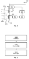
- Fig. 1 is a schematic diagram illustrating part of a vehicle interior according to an embodiment.
- the vehicle interior is part of a vehicle 100.
- the vehicle 100 is preferably an automotive vehicle.
- An electronic control system 200 is schematically illustrated as positioned at a dashboard of the vehicle 100.
- the electronic control system 200 can be positioned elsewhere in the vehicle interior.
- the electronic control system 200 can be positioned at the steering wheel, below or above the windshield, in a ceiling of the vehicle 100 or at an A-pillar of the vehicle 100.
- different regions of the vehicle interior (such as only the front seat, only the back seat, or the front seat and the back seat) can be monitored.
- the electronic control system 200 at least comprises a light emitter and a light sensor.
- the light emitter and the light sensor are directed to a vehicle occupant 300.
- the vehicle occupant 300 is a vehicle driver, but the vehicle occupant 300 could be a vehicle passenger.
- the light emitter is arranged to emit light 400a and the light sensor is arranged to receive light 400b as emitted by the light emitter and after having been reflected by the vehicle occupant 300.
- the electronic control system 200 with its light emitter and light sensor directed toward the vehicle driver or any of the other vehicle occupants, can be configured to detect and estimate driver drowsiness, driver gaze direction, occupant position, etc.
- the estimation can be used for safety applications such as attentiveness warnings, automatic braking and other safety related actions.
- the light sensor needs to receive light 400b as reflected by the vehicle occupant 300.
- Sunlight provides a problem for some light sensors. It is especially the varied intensity of light in the faces of the vehicle occupant 300 that cause difficulties for image processing performed as part of the detection and estimation in the electronic control system 200. An even illumination of the face can be achieved by reducing the exposure time and/or the active illumination (from lights/flashes). But the sun creates shadows from sun visors, pillars etc. and/or illuminates the face only from the side, which again causes difficulties for the image processing. Sunlight in most situations represents the strongest light source. Hence, for an optical light sensor there might be side effects due to very high intensive sunlight which can occur as oversaturation in the light sensor caused by the sunlight effect.
- the embodiments disclosed herein are based on, by means of the light emitter, creating an artificial interior illumination (inside the vehicle interior) which is not affected from the sunlight and not visible for humans, and where the light sensor is still sensitive enough in terms of signal to noise ratio for the electronic control system 200 to use the reflected light 400b for image processing.
- the embodiments disclosed herein are based on the light emitter emitting light of a very specific wave length within the vehicle interior and receiving the light with a light sensor only sensing that specific light. This would enable the electronic control system 200 to obtain images of the vehicle occupant 300 without experiencing the above problems caused by sunlight.
- the embodiments disclosed herein are based on the light sensor sensing light in the gaps in the sunlight spectrum known as Fraunhofer lines in order to fade potential saturation condition caused by the sunlight intensity. This requires the light emitter to be arranged to emit such artificial light.
- Fig. 2 is a schematic diagram showing functional units of the electronic control system 200 for monitoring the vehicle occupant 300 according to an embodiment.
- the electronic control system 200 comprises a light emitter 210.
- the light emitter 210 is arranged to emit light 400a.
- the light 400a comprises a Fraunhofer line wavelength.
- the light 400a is emitted inside a wavelength interval.
- the wavelength interval has a width of less than 50 nm, preferably less than 25 nm, even preferably less than 10 nm.
- the electronic control system 200 comprises a light sensor 220.
- the light sensor 220 is arranged to receive light 400b.
- the received light 400b has been emitted by the light emitter 210 and is by the light sensor 220 received after having been reflected by the vehicle occupant 300.
- the light sensor 220 is configured to sense light 400b only within the wavelength interval. In this respect, although the light sensor 220 may receive light outside the wavelength interval, it only registers received light 400b (and thus senses the light 400b) within the wavelength interval.
- such an electronic control system 200 can define a driver monitoring system comprising a light emitter 210 and a light sensor 220 and being characterized in that the emitted light 400a is within Fraunhofer line wavelengths and the light sensor 220 is adapted to sense such light 400b.
- Fraunhofer line wavelengths There are different examples of Fraunhofer line wavelengths. Three examples of Fraunhofer line wavelengths are wavelengths around 759 nm (denoted Fraunhofer Line A and caused by the oxygen in the atmosphere), around 823 nm (denoted Fraunhofer Line Z and caused by the oxygen in the atmosphere) and around 899 nm (denoted Fraunhofer Line y and caused by the oxygen in the atmosphere), and around 940 nm.
- the Fraunhofer line wavelength emitted by the light emitter 210 is one of 759 nm, 823 nm, 899 nm, and 940 nm.
- the light sensor 220 can thus be configured to sense light inside a wavelength interval comprising at least one of 759 nm, 823 nm, 899 nm, and 940 nm.
- the Fraunhofer line wavelength emitted by the light emitter 210 is 899 nm and hence preferably the light sensor 220 is configured to sense light inside a wavelength interval comprising 899 nm.
- the electronic control system 200 further comprises a diffuser 230.
- the diffuser 230 is arranged to diffuse the emitted light 400a before the light 400a is reflected by the vehicle occupant 300. Whether to use a diffuser 230 or not can depend on the light spreading properties of the light emitter 210.
- the electronic control system 200 further comprises a bandpass filter 240.
- the bandpass filter 240 is an optical bandpass filter.
- the bandpass filter 240 is arranged to filter the received light 400b such that the received light 400b only is sensed within the wavelength interval.
- the bandpass filter 240 has a passband frequency interval equal to the wavelength interval specified above.
- the bandpass filter 240 has a passband frequency interval comprising one of 759 nm, 823 nm, 899 nm, and 940 nm.
- the bandpass filter 240 lets through the received light 400b but reflects other light 400b, for example representing natural sunlight. This enables the use of a light sensor 220 that as such is sensitive to light also outside the wavelength interval specified above.
- the electronic control system 200 can be arranged such that the light emitter 210 and the light sensor 220 are arranged to face a vehicle interior. Different placements of the electronic control system 200 have also been described above. Thus, the light emitter 210 and the light sensor 220 can be positioned at a dashboard of the vehicle 100, at the steering wheel of the vehicle 100, below or above the windshield of the vehicle 100, in a ceiling of the vehicle 100 or at an A-pillar of the vehicle 100.
- the electronic control system 200 further comprises an image generator 250.
- the image generator 250 is configured to generate an image of the vehicle occupant 300 from the light 400b sensed by the light sensor 220.
- the electronic control system 200 could further comprise a movement estimator 260.
- the movement estimator 260 is configured to estimate movement of the vehicle occupant 300 in the image.
- the estimated movement of the vehicle occupant 300 could be used as input to a vehicle control system 270.
- the vehicle control system 270 can be configured to detect driver drowsiness and to perform actions, such as vehicle control, in response to having detected driver drowsiness.
- the electronic control system 200 further comprises a vehicle control system 270 configured to perform vehicle control based on the estimated movement.
- vehicle control systems 270 There are different examples of vehicle control systems 270.
- the vehicle control could relate to any of Adaptive Cruise Control (ACC) Automatic Emergency Braking (AEB) Autonomous Driving, AD, and warning indication provision to a user interface 280. Further description thereof is described below.
- ACC Adaptive Cruise Control
- AEB Automatic Emergency Braking
- AD Warning indication provision to a user interface 280. Further description thereof is described below.
- the vehicle control system 270 can by means of the movement estimator 260 be configured to obtain instructions as provided by the vehicle occupant 300 using a gesture-based user interface.
- the movement estimator 260 can be configured to classify the movement of the vehicle occupant 300 into one gesture in a set of predefined gestures. Each such predefined gesture can correspond to a particular user input command and hence, upon having classified which of the gestures the vehicle occupant 300 has performed, the vehicle control system 270 can perform an action corresponding to the user input command of the thus classified gesture.
- the light emitter 210 could be composed of an array of semiconductor-based laser diodes, such as a vertical-cavity surface-emitting laser (VCSEL) array with a wavelength close to 759 nm, 823 nm, 899 nm, or 940 nm.
- VCSEL arrays have a strongly reduced temperature drift in comparison to standard infrared (IR) light emitting diodes (LEDs).
- the light sensor 220 could be configured to sense the light 400b using contrast detection. Hence the light sensor 220 does not need to be configured to sense different colours but only different shades of luminance.
- the light sensor 220 should sense incoming light at a wavelength close to 759 nm, 823 nm, 899 nm, or 940 nm.
- the light sensor 220 can have an image sensor pixel resolution of 752 by 480 pixels.
- the light sensor 220 can have a global shutter mechanism. Having a global shutter mechanism prevents smearing effects which otherwise could appear as a result of objects moving within the image being captured.
- the light sensor 220 can be an APTINA Wide-VGA, MT9V024 digital image sensor, with a global shutter mechanism). This light sensor has especially an enhanced near-infrared (NIR) performance.
- NIR near-infrared
- the light emitter 210 and the light sensor 220 can be synchronized.
- the light sensor 220 can set its exposure time such that the light sensor 220 only senses receives light 400b during flashes when the light emitter 210 emits light 400a.
- FIG. 3 illustrating a method for monitoring a vehicle occupant 300 according to an embodiment.
- the light emitter 210 emits light 400a.
- the light 400a comprises a Fraunhofer line wavelength.
- the light is emitted inside a wavelength interval having a width of less than 50 nm, preferably less than 25 nm, even preferably less than 10 nm.
- the light sensor 220 receives light 400b.
- the received light 400b has been emitted by the light emitter 210 and is by the light sensor 220 received after having been reflected by the vehicle occupant 300.
- the light sensor 220 detects the received light 400b only within the wavelength interval.
- At least steps S102 and steps S106 can be controlled by the electronic control system 200.
- the electronic control system 200 can be configured to cause the light emitter 210 to perform step S102 and the light sensor 220 to perform step S106.
- Fig. 4 illustrating methods for monitoring a vehicle occupant 300 according to further embodiments. It is assumed that steps S102, S106, S110 are performed as disclosed above and a thus repeated description thereof is therefore omitted.
- the electronic control system 200 can comprise a diffuser 230.
- the method for monitoring the vehicle occupant 300 comprises step S104:
- the electronic control system 200 further comprises a bandpass filter 240 to filter the received light 400b.
- the method for monitoring the vehicle occupant 300 comprises step S108:
- the electronic control system 200 can comprise an image generator 250 and a movement estimator 260.
- the method for monitoring the vehicle occupant 300 comprises steps S112 and S114:
- the electronic control system 200 can be configured to perform once having estimated the movement of the vehicle occupant 300 as in step S114.
- the estimated movement of the vehicle occupant 300 can be used as input to a vehicle control system 270.
- the electronic control system 200 provides the estimated movement of the vehicle occupant 300 as input to the vehicle control system 270.
- the vehicle control system 270 is part of, or at least controlled by, the electronic control system 200.
- the electronic control system 200 is configured to perform step S116:
- vehicle control systems 270 There are different examples of vehicle control systems 270. As disclosed above, the vehicle control system 270 could be an Adaptive Cruise Control (ACC) system, an Automatic Emergency Braking (AEB) system, or an Autonomous Driving (AD) system.
- ACC Adaptive Cruise Control
- AEB Automatic Emergency Braking
- AD Autonomous Driving
- the electronic control system 200 is configured to perform at least one of steps S116a, S116b, and S116c as part of step S116:
- steps S116a-S116c could be combined with at least one other step of steps S116a-S116c.
- the electronic control system 200 is configured to provide warnings (such as sounds or visual alerts) to the vehicle driver of the automotive vehicle 100.
- the electronic control system 200 is configured to perform step S116d as part of step S116:
- the vehicle control system 270 can by means of the movement estimator 260 be configured to obtain instructions as provided by the vehicle occupant 300 using a gesture-based user interface.
- vehicle occupants 300 There could be different examples of vehicle occupants 300. As disclosed above, the vehicle occupant 300 could be a vehicle driver or a vehicle passenger.
- the herein disclosed electronic control system 200 could be part of the automotive vehicle 100.
- the automotive vehicle 100 comprises an electronic control system 200 as herein disclosed.
Landscapes
- Engineering & Computer Science (AREA)
- Transportation (AREA)
- Mechanical Engineering (AREA)
- Chemical & Material Sciences (AREA)
- Combustion & Propulsion (AREA)
- Automation & Control Theory (AREA)
- Physics & Mathematics (AREA)
- Mathematical Physics (AREA)
- Human Computer Interaction (AREA)
- Traffic Control Systems (AREA)
Abstract
There is provided mechanisms for monitoring a vehicle occupant (300). An electronic control system (200) comprises a light emitter (210). The light emitter is arranged to emit light comprising a Fraunhofer line wavelength. The light is emitted inside a wavelength interval having a width of less than 50 nm, preferably less than 25 nm, even preferably less than 10 nm. The electronic control system comprises a light sensor (220). The light sensor is arranged to receive light having been emitted by the light emitter after having been reflected by the vehicle occupant. The light sensor is configured to sense the light only within the wavelength interval.
Description
- Embodiments presented herein relate to monitoring a vehicle occupant, and particularly to an electronic control system and a method for monitoring a vehicle occupant.
- Driver fatigue has been identified as a safety issue. Driver fatigue manifests itself in drowsiness, a state of diminished mental alertness, in turn impairing an individual's ability to operate a vehicle safely and, thereby, increasing the risk of human error that could lead to fatalities and injuries.
- Drowsiness is the body's reaction to fatigue and drowsiness slows reaction time, decreases awareness, and impairs judgment. Studies as have been done show that drivers tend to underreport drowsiness, either because they are not aware of being drowsy or underestimate the extent to which they are impaired by drowsiness. Incidence of impairing drowsiness is underestimated because it is so difficult to quantify and measure.
- Driver's drowsiness can be measured by two classes of phenomena: physical and physiological on the one hand and vehicle state variables on the other hand. Physical and physiological measurements include the measurement of brain wave or Electroencephalogram (EEG). PERCLOS (PERcent eyelid CLOSure) is one of the most widely accepted measures in scientific literature for measurement and detection of drowsiness.
- Drowsiness detection systems have been developed which work based on measurement of physical and physiological features, and can provide very good detection accuracy. However, they have some shortcomings. The problem with an EEG is that it requires the use of electrodes to be attached to the scalp and that makes it very impractical to use. Eye closure activity can also provide good detection accuracy, but capturing eye image unobtrusively can be expensive and challenging under certain conditions. Changes in light conditions, correction glasses, angle of face, and other conditions can seriously affect the performance of image processing systems.
- Hence, there is still a need for improved mechanisms for monitoring a vehicle occupant.
- An object of embodiments herein is to provide efficient monitoring of a vehicle occupant.
- According to a first aspect there is presented an electronic control system for monitoring a vehicle occupant. The electronic control system comprises a light emitter. The light emitter is arranged to emit light comprising a Fraunhofer line wavelength. The light is emitted inside a wavelength interval having a width of less than 50 nm, preferably less than 25 nm, even preferably less than 10 nm. The electronic control system comprises a light sensor. The light sensor is arranged to receive light having been emitted by the light emitter after having been reflected by the vehicle occupant. The light sensor is configured to sense the light only within the wavelength interval Advantageously this electronic control system provides efficient monitoring of a vehicle occupant.
- Advantageously this electronic control system enables oversaturation effects caused by natural sunlight to be avoided, or at least mitigated.
- According to a second aspect there is presented a method for monitoring a vehicle occupant. The method comprises emitting, by a light emitter, light comprising a Fraunhofer line wavelength. The light is emitted inside a wavelength interval having a width of less than 50 nm, preferably less than 25 nm, even preferably less than 10 nm. The method comprises receiving, by a light sensor, light having been emitted by the light emitter after having been reflected by the vehicle occupant. The method comprises sensing, by the light sensor, the light only within the wavelength interval.
- It is to be noted that any feature of the first and second aspects may be applied to any other aspect, wherever appropriate. Likewise, any advantage of the first aspect may equally apply to the second aspect, respectively, and vice versa. Other objectives, features and advantages of the enclosed embodiments will be apparent from the following detailed disclosure, from the attached dependent claims as well as from the drawings.
- Generally, all terms used in the claims are to be interpreted according to their ordinary meaning in the technical field, unless explicitly defined otherwise herein. All references to "a/an/the element, apparatus, component, means, step, etc." are to be interpreted openly as referring to at least one instance of the element, apparatus, component, means, step, etc., unless explicitly stated otherwise. The steps of any method disclosed herein do not have to be performed in the exact order disclosed, unless explicitly stated.
- The inventive concept is now described, by way of example, with reference to the accompanying drawings, in which:
-
Fig. 1 is a schematic diagram illustrating part of a vehicle interior according to an embodiment; -
Fig. 2 is a schematic diagram showing functional units of a electronic control system according to an embodiment; and -
Figs. 3 and4 are flowcharts of methods according to embodiments. - The inventive concept will now be described more fully hereinafter with reference to the accompanying drawings, in which certain embodiments of the inventive concept are shown. This inventive concept may, however, be embodied in many different forms and should not be construed as limited to the embodiments set forth herein; rather, these embodiments are provided by way of example so that this disclosure will be thorough and complete, and will fully convey the scope of the inventive concept to those skilled in the art. Like numbers refer to like elements throughout the description. Any step or feature illustrated by dashed lines should be regarded as optional.
- The embodiments disclosed herein relate to mechanisms for monitoring a vehicle occupant. In order to obtain such mechanisms there is provided an electronic control system, and a method performed by the electronic control system.
-
Fig. 1 is a schematic diagram illustrating part of a vehicle interior according to an embodiment. The vehicle interior is part of avehicle 100. Thevehicle 100 is preferably an automotive vehicle. Anelectronic control system 200 is schematically illustrated as positioned at a dashboard of thevehicle 100. However, theelectronic control system 200 can be positioned elsewhere in the vehicle interior. For example theelectronic control system 200 can be positioned at the steering wheel, below or above the windshield, in a ceiling of thevehicle 100 or at an A-pillar of thevehicle 100. Depending on the placement of theelectronic control system 200 different regions of the vehicle interior (such as only the front seat, only the back seat, or the front seat and the back seat) can be monitored. As will be further disclosed below, theelectronic control system 200 at least comprises a light emitter and a light sensor. The light emitter and the light sensor are directed to avehicle occupant 300. In the illustrative example ofFig. 1 thevehicle occupant 300 is a vehicle driver, but thevehicle occupant 300 could be a vehicle passenger. Particularly, the light emitter is arranged to emitlight 400a and the light sensor is arranged to receivelight 400b as emitted by the light emitter and after having been reflected by thevehicle occupant 300. - The
electronic control system 200, with its light emitter and light sensor directed toward the vehicle driver or any of the other vehicle occupants, can be configured to detect and estimate driver drowsiness, driver gaze direction, occupant position, etc. The estimation can be used for safety applications such as attentiveness warnings, automatic braking and other safety related actions. In order to do so the light sensor needs to receivelight 400b as reflected by thevehicle occupant 300. - Sunlight provides a problem for some light sensors. It is especially the varied intensity of light in the faces of the
vehicle occupant 300 that cause difficulties for image processing performed as part of the detection and estimation in theelectronic control system 200. An even illumination of the face can be achieved by reducing the exposure time and/or the active illumination (from lights/flashes). But the sun creates shadows from sun visors, pillars etc. and/or illuminates the face only from the side, which again causes difficulties for the image processing. Sunlight in most situations represents the strongest light source. Hence, for an optical light sensor there might be side effects due to very high intensive sunlight which can occur as oversaturation in the light sensor caused by the sunlight effect. - In general terms, the embodiments disclosed herein are based on, by means of the light emitter, creating an artificial interior illumination (inside the vehicle interior) which is not affected from the sunlight and not visible for humans, and where the light sensor is still sensitive enough in terms of signal to noise ratio for the
electronic control system 200 to use the reflected light 400b for image processing. - In general terms, the embodiments disclosed herein are based on the light emitter emitting light of a very specific wave length within the vehicle interior and receiving the light with a light sensor only sensing that specific light. This would enable the
electronic control system 200 to obtain images of thevehicle occupant 300 without experiencing the above problems caused by sunlight. - Particularly, the embodiments disclosed herein are based on the light sensor sensing light in the gaps in the sunlight spectrum known as Fraunhofer lines in order to fade potential saturation condition caused by the sunlight intensity. This requires the light emitter to be arranged to emit such artificial light.
- Particular reference is now made to
Fig. 2. Fig. 2 is a schematic diagram showing functional units of theelectronic control system 200 for monitoring thevehicle occupant 300 according to an embodiment. - The
electronic control system 200 comprises alight emitter 210. Thelight emitter 210 is arranged to emit light 400a. The light 400a comprises a Fraunhofer line wavelength. Thelight 400a is emitted inside a wavelength interval. The wavelength interval has a width of less than 50 nm, preferably less than 25 nm, even preferably less than 10 nm. - The
electronic control system 200 comprises alight sensor 220. Thelight sensor 220 is arranged to receive light 400b. The received light 400b has been emitted by thelight emitter 210 and is by thelight sensor 220 received after having been reflected by thevehicle occupant 300. Thelight sensor 220 is configured to sense light 400b only within the wavelength interval. In this respect, although thelight sensor 220 may receive light outside the wavelength interval, it only registers received light 400b (and thus senses the light 400b) within the wavelength interval. - Hence, such an
electronic control system 200 can define a driver monitoring system comprising alight emitter 210 and alight sensor 220 and being characterized in that the emitted light 400a is within Fraunhofer line wavelengths and thelight sensor 220 is adapted to sensesuch light 400b. - Embodiments relating to further details of the
electronic control system 200 will now be disclosed. - There are different examples of Fraunhofer line wavelengths. Three examples of Fraunhofer line wavelengths are wavelengths around 759 nm (denoted Fraunhofer Line A and caused by the oxygen in the atmosphere), around 823 nm (denoted Fraunhofer Line Z and caused by the oxygen in the atmosphere) and around 899 nm (denoted Fraunhofer Line y and caused by the oxygen in the atmosphere), and around 940 nm. Hence, according to an embodiment the Fraunhofer line wavelength emitted by the
light emitter 210 is one of 759 nm, 823 nm, 899 nm, and 940 nm. Thelight sensor 220 can thus be configured to sense light inside a wavelength interval comprising at least one of 759 nm, 823 nm, 899 nm, and 940 nm. Preferably, the Fraunhofer line wavelength emitted by thelight emitter 210 is 899 nm and hence preferably thelight sensor 220 is configured to sense light inside a wavelength interval comprising 899 nm. - According to an embodiment the
electronic control system 200 further comprises adiffuser 230. Thediffuser 230 is arranged to diffuse the emitted light 400a before the light 400a is reflected by thevehicle occupant 300. Whether to use adiffuser 230 or not can depend on the light spreading properties of thelight emitter 210. - According to an embodiment the
electronic control system 200 further comprises abandpass filter 240. Thebandpass filter 240 is an optical bandpass filter. Thebandpass filter 240 is arranged to filter the received light 400b such that the received light 400b only is sensed within the wavelength interval. Hence, thebandpass filter 240 has a passband frequency interval equal to the wavelength interval specified above. Thus, according to an embodiment thebandpass filter 240 has a passband frequency interval comprising one of 759 nm, 823 nm, 899 nm, and 940 nm. As schematically illustrated inFig. 2 , thebandpass filter 240 lets through the received light 400b but reflectsother light 400b, for example representing natural sunlight. This enables the use of alight sensor 220 that as such is sensitive to light also outside the wavelength interval specified above. - There could be different ways to place the
electronic control system 200. As disclosed above, theelectronic control system 200 can be arranged such that thelight emitter 210 and thelight sensor 220 are arranged to face a vehicle interior. Different placements of theelectronic control system 200 have also been described above. Thus, thelight emitter 210 and thelight sensor 220 can be positioned at a dashboard of thevehicle 100, at the steering wheel of thevehicle 100, below or above the windshield of thevehicle 100, in a ceiling of thevehicle 100 or at an A-pillar of thevehicle 100. - According to an embodiment the
electronic control system 200 further comprises animage generator 250. Theimage generator 250 is configured to generate an image of thevehicle occupant 300 from the light 400b sensed by thelight sensor 220. Theelectronic control system 200 could further comprise amovement estimator 260. Themovement estimator 260 is configured to estimate movement of thevehicle occupant 300 in the image. - The estimated movement of the
vehicle occupant 300 could be used as input to avehicle control system 270. Thevehicle control system 270 can be configured to detect driver drowsiness and to perform actions, such as vehicle control, in response to having detected driver drowsiness. Hence according to an embodiment theelectronic control system 200 further comprises avehicle control system 270 configured to perform vehicle control based on the estimated movement. - There are different examples of
vehicle control systems 270. For example, the vehicle control could relate to any of Adaptive Cruise Control (ACC) Automatic Emergency Braking (AEB) Autonomous Driving, AD, and warning indication provision to auser interface 280. Further description thereof is described below. - Additionally or alternatively, the
vehicle control system 270 can by means of themovement estimator 260 be configured to obtain instructions as provided by thevehicle occupant 300 using a gesture-based user interface. In more detail, themovement estimator 260 can be configured to classify the movement of thevehicle occupant 300 into one gesture in a set of predefined gestures. Each such predefined gesture can correspond to a particular user input command and hence, upon having classified which of the gestures thevehicle occupant 300 has performed, thevehicle control system 270 can perform an action corresponding to the user input command of the thus classified gesture. - There are different examples of suitable
light emitters 210. For example, thelight emitter 210 could be composed of an array of semiconductor-based laser diodes, such as a vertical-cavity surface-emitting laser (VCSEL) array with a wavelength close to 759 nm, 823 nm, 899 nm, or 940 nm. VCSEL arrays have a strongly reduced temperature drift in comparison to standard infrared (IR) light emitting diodes (LEDs). - There are different examples of suitable
light sensors 220. For example, thelight sensor 220 could be configured to sense the light 400b using contrast detection. Hence thelight sensor 220 does not need to be configured to sense different colours but only different shades of luminance. Thelight sensor 220 should sense incoming light at a wavelength close to 759 nm, 823 nm, 899 nm, or 940 nm. Thelight sensor 220 can have an image sensor pixel resolution of 752 by 480 pixels. Thelight sensor 220 can have a global shutter mechanism. Having a global shutter mechanism prevents smearing effects which otherwise could appear as a result of objects moving within the image being captured. Thelight sensor 220 can be an APTINA Wide-VGA, MT9V024 digital image sensor, with a global shutter mechanism). This light sensor has especially an enhanced near-infrared (NIR) performance. - Further, the
light emitter 210 and thelight sensor 220 can be synchronized. For example, thelight sensor 220 can set its exposure time such that thelight sensor 220 only senses receives light 400b during flashes when thelight emitter 210 emits light 400a. - Reference is now made to
Fig. 3 illustrating a method for monitoring avehicle occupant 300 according to an embodiment. - S102: The
light emitter 210 emits light 400a. The light 400a comprises a Fraunhofer line wavelength. The light is emitted inside a wavelength interval having a width of less than 50 nm, preferably less than 25 nm, even preferably less than 10 nm. - S106: The
light sensor 220 receives light 400b. The received light 400b has been emitted by thelight emitter 210 and is by thelight sensor 220 received after having been reflected by thevehicle occupant 300. - S110: The
light sensor 220 detects the received light 400b only within the wavelength interval. - At least steps S102 and steps S106 can be controlled by the
electronic control system 200. Hence, theelectronic control system 200 can be configured to cause thelight emitter 210 to perform step S102 and thelight sensor 220 to perform step S106. - Reference is now made to
Fig. 4 illustrating methods for monitoring avehicle occupant 300 according to further embodiments. It is assumed that steps S102, S106, S110 are performed as disclosed above and a thus repeated description thereof is therefore omitted. - There may be different ways to manipulate the light 400a before it is reflected by the
vehicle occupant 300. For example, as disclosed above, theelectronic control system 200 can comprise adiffuser 230. Hence, according to an embodiment the method for monitoring thevehicle occupant 300 comprises step S104: - S104: The
diffuser 230 diffuses the emitted light 400a before the emitted light 400a is reflected by thevehicle occupant 300. Step S104 can be controlled by theelectronic control system 200. Hence, theelectronic control system 200 can be configured to selectively determine whether to diffuse the emitted light 400a or not. - Further, as disclosed above, to an embodiment the
electronic control system 200 further comprises abandpass filter 240 to filter the received light 400b. - Hence, according to an embodiment the method for monitoring the
vehicle occupant 300 comprises step S108: - S108: The
bandpass filter 240 filters the received light 400b such that the received light 400b only is sensed within the wavelength interval. - There may be different ways to process the light 400b sensed by the
light sensor 220. For example, as disclosed above, theelectronic control system 200 can comprise animage generator 250 and amovement estimator 260. Hence, according to an embodiment the method for monitoring thevehicle occupant 300 comprises steps S112 and S114: - S112: The
image generator 250 generates an image of thevehicle occupant 300 from the light 400b sensed by thelight sensor 220. How to generate an image from input from a light sensor is as such known in the art and further description thereof is therefore omitted. - S114: The
movement estimator 260 estimates movement of thevehicle occupant 300 in the thus generated image. How to estimate movement of an object in an image is as such known in the art and further description thereof is therefore omitted. - There are different operations that the
electronic control system 200 can be configured to perform once having estimated the movement of thevehicle occupant 300 as in step S114. For example, as disclosed above, the estimated movement of thevehicle occupant 300 can be used as input to avehicle control system 270. Hence, according to an embodiment theelectronic control system 200 provides the estimated movement of thevehicle occupant 300 as input to thevehicle control system 270. - According to some embodiments the
vehicle control system 270 is part of, or at least controlled by, theelectronic control system 200. Hence, according to an embodiment theelectronic control system 200 is configured to perform step S116: - S116: The
electronic control system 200 performs vehicle control using the at least onevehicle control system 270 and based on the estimated movement of thevehicle occupant 300. The vehicle control can depend on the level of drowsiness of thevehicle occupant 300. - There are different examples of
vehicle control systems 270. As disclosed above, thevehicle control system 270 could be an Adaptive Cruise Control (ACC) system, an Automatic Emergency Braking (AEB) system, or an Autonomous Driving (AD) system. - Hence, according to an embodiment the
electronic control system 200 is configured to perform at least one of steps S116a, S116b, and S116c as part of step S116: - S116a: The
electronic control system 200 performs Adaptive Cruise Control (ACC). Theelectronic control system 200 is thereby configured to adjust the speed of theautomotive vehicle 100 depending, for example, on a level of drowsiness detected for thevehicle occupant 300. - S116b: The
electronic control system 200 performs Automatic Emergency Braking (AEB). Theelectronic control system 200 is thereby configured to control a braking system of theautomotive vehicle 100 to avoid collision which otherwise might be caused due to drowsiness of thevehicle occupant 300. - S116c: The
electronic control system 200 performs Autonomous Driving (AD). Theelectronic control system 200 is thereby configured to control navigation of theautomotive vehicle 100 without human input. - Any given step of steps S116a-S116c could be combined with at least one other step of steps S116a-S116c.
- Additionally or alternatively, the
electronic control system 200 is configured to provide warnings (such as sounds or visual alerts) to the vehicle driver of theautomotive vehicle 100. Hence, according to an embodiment theelectronic control system 200 is configured to perform step S116d as part of step S116: - S116d: The
electronic control system 200 provides a warning indication to theuser interface 280. - Step S116d could be combined with any of step S116a-S116c.
- Additionally or alternatively, as disclosed above, the
vehicle control system 270 can by means of themovement estimator 260 be configured to obtain instructions as provided by thevehicle occupant 300 using a gesture-based user interface. - There could be different examples of
vehicle occupants 300. As disclosed above, thevehicle occupant 300 could be a vehicle driver or a vehicle passenger. - The herein disclosed
electronic control system 200 could be part of theautomotive vehicle 100. Hence, according to an embodiment theautomotive vehicle 100 comprises anelectronic control system 200 as herein disclosed. - The inventive concept has mainly been described above with reference to a few embodiments. However, as is readily appreciated by a person skilled in the art, other embodiments than the ones disclosed above are equally possible within the scope of the inventive concept, as defined by the appended patent claims.
Claims (15)
- An electronic control system (200) for monitoring a vehicle occupant (300), the electronic control system (200) comprising:a light emitter (210) arranged to emit light (400a) comprising a Fraunhofer line wavelength, wherein the light is emitted inside a wavelength interval having a width of less than 50 nm, preferably less than 25 nm, even preferably less than 10 nm; anda light sensor (220) arranged to receive light (400b) having been emitted by the light emitter (210) after having been reflected by the vehicle occupant (300), and configured to sense said light (400b) only within said wavelength interval.
- The electronic control system (200) according to claim 1, wherein the Fraunhofer line wavelength is one of 759 nm, 823 nm, 899 nm, and 940 nm.
- The electronic control system (200) according to any of the preceding claims, further comprising:a diffuser (230) arranged to diffuse said emitted light (400a) before being reflected by the vehicle occupant (300).
- The electronic control system (200) according to any of the preceding claims, further comprising:a bandpass filter (240) arranged to filter said received light (400b) such that said received light (400b) only is sensed within said wavelength interval.
- The electronic control system (200) according to any of the preceding claims, wherein the light emitter (210) and the light sensor (220) are arranged to face a vehicle interior.
- The electronic control system (200) according to according to any of the preceding claims, further comprising:an image generator (250) configured to generate an image of the vehicle occupant (300) from the light (400b) sensed by the light sensor (220); anda movement estimator (260) configured to estimate movement of the vehicle occupant (300) in said image.
- The electronic control system (200) according to claim 6, further comprising:a vehicle control system (270) configured to perform vehicle control based on the estimated movement.
- The electronic control system (200) according to claim 7, wherein vehicle control comprises at least one of Adaptive Cruise Control, ACC, Automatic Emergency Braking, AEB, Autonomous Driving, AD, and warning indication provision to a user interface (280).
- An automotive vehicle (100) comprising an electronic control system (200) according to according to any of the preceding claims.
- A method for monitoring a vehicle occupant (300), the method comprising:emitting (S102), by a light emitter (210), light comprising a Fraunhofer line wavelength, wherein the light is emitted inside a wavelength interval having a width of less than 50 nm, preferably less than 25 nm, even preferably less than 10 nm;receiving (S106), by a light sensor (220), light (400b) having been emitted by the light emitter (210) after having been reflected by the vehicle occupant (300); andsensing (S110), by said light sensor (220), said light (400b) only within said wavelength interval.
- The method according to claim 10, further comprising:diffusing (S104), by a diffuser (230), said emitted light (400a) before being reflected by the vehicle occupant (300).
- The method according to claim 10, further comprising:filtering (S108), by a bandpass filter (240), said received light (400b) such that said received light (400b) only is sensed within said wavelength interval.
- The method according to claim 10 or 11, further comprising:generating (S112), by an image generator (250), an image of the vehicle occupant (300) from the light (400b) sensed by the light sensor (220); andestimating movement (S114), by a movement estimator (260), of the vehicle occupant (300) in said image.
- The method according to claim 12, further comprising:performing vehicle control (S116), by a vehicle control system (270), based on the estimated movement.
- The method according to claim 14, wherein performing vehicle control comprises at least one of:performing (S116a) Adaptive Cruise Control, ACC;performing (S116b) Automatic Emergency Braking, AEB;performing (S116c) Autonomous Driving, AD; andproviding (S116d) a warning indication to a user interface (280).
Priority Applications (1)
| Application Number | Priority Date | Filing Date | Title |
|---|---|---|---|
| EP16168971.6A EP3243684A1 (en) | 2016-05-10 | 2016-05-10 | Vehicle occupant monitoring |
Applications Claiming Priority (1)
| Application Number | Priority Date | Filing Date | Title |
|---|---|---|---|
| EP16168971.6A EP3243684A1 (en) | 2016-05-10 | 2016-05-10 | Vehicle occupant monitoring |
Publications (1)
| Publication Number | Publication Date |
|---|---|
| EP3243684A1 true EP3243684A1 (en) | 2017-11-15 |
Family
ID=55967111
Family Applications (1)
| Application Number | Title | Priority Date | Filing Date |
|---|---|---|---|
| EP16168971.6A Withdrawn EP3243684A1 (en) | 2016-05-10 | 2016-05-10 | Vehicle occupant monitoring |
Country Status (1)
| Country | Link |
|---|---|
| EP (1) | EP3243684A1 (en) |
Cited By (1)
| Publication number | Priority date | Publication date | Assignee | Title |
|---|---|---|---|---|
| DE102017130628A1 (en) | 2017-12-20 | 2019-07-11 | Autoliv Development Ab | System, method and computer program product for increasing driving safety in traffic |
Citations (3)
| Publication number | Priority date | Publication date | Assignee | Title |
|---|---|---|---|---|
| EP1653248A1 (en) * | 2004-10-28 | 2006-05-03 | Delphi Technologies, Inc. | Actively-illuminating optical sensing system for an automobile |
| US20150042477A1 (en) * | 2009-03-30 | 2015-02-12 | Tobii Technology Ab | Eye closure detection using structured illumination |
| DE102014216053A1 (en) * | 2014-08-13 | 2016-02-18 | Bayerische Motoren Werke Aktiengesellschaft | Adjustment of the illumination wavelength during eye detection |
-
2016
- 2016-05-10 EP EP16168971.6A patent/EP3243684A1/en not_active Withdrawn
Patent Citations (3)
| Publication number | Priority date | Publication date | Assignee | Title |
|---|---|---|---|---|
| EP1653248A1 (en) * | 2004-10-28 | 2006-05-03 | Delphi Technologies, Inc. | Actively-illuminating optical sensing system for an automobile |
| US20150042477A1 (en) * | 2009-03-30 | 2015-02-12 | Tobii Technology Ab | Eye closure detection using structured illumination |
| DE102014216053A1 (en) * | 2014-08-13 | 2016-02-18 | Bayerische Motoren Werke Aktiengesellschaft | Adjustment of the illumination wavelength during eye detection |
Cited By (1)
| Publication number | Priority date | Publication date | Assignee | Title |
|---|---|---|---|---|
| DE102017130628A1 (en) | 2017-12-20 | 2019-07-11 | Autoliv Development Ab | System, method and computer program product for increasing driving safety in traffic |
Similar Documents
| Publication | Publication Date | Title |
|---|---|---|
| CN105144199B (en) | Imaging device-based occupant monitoring system supporting multiple functions | |
| US11713048B2 (en) | Integration of occupant monitoring systems with vehicle control systems | |
| US10787189B2 (en) | Occupant monitoring systems and methods | |
| US10864918B2 (en) | Vehicle and method for supporting driving safety thereof | |
| US10277837B2 (en) | System and method for monitoring a driver of a vehicle | |
| KR101687125B1 (en) | Object recognition in low-lux and high-lux conditions | |
| US20150238087A1 (en) | Biological information measurement device and input device utilizing same | |
| EP2312551A1 (en) | Driver awareness degree judgment device, method, and program | |
| WO2015175435A1 (en) | Driver health and fatigue monitoring system and method | |
| WO2019200434A9 (en) | Infrared light source protective system | |
| EP3912149B1 (en) | Method and system for monitoring a person using infrared and visible light | |
| US20160046295A1 (en) | Method and device for determining a reaction time of a vehicle driver | |
| US20220258771A1 (en) | Method to detect driver readiness for vehicle takeover requests | |
| JP2008204107A (en) | Careless warning device, vehicle equipment control method of careless warning device, and vehicle control device program | |
| JP6433383B2 (en) | Floodlight device | |
| EP3243684A1 (en) | Vehicle occupant monitoring | |
| CN109204323B (en) | System and method for dealing with light source damage | |
| US20190156133A1 (en) | Vehicle driving support apparatus and vehicle driving support program | |
| JP2009031004A (en) | Drinking determination device and program | |
| US12298393B2 (en) | Flight time sensor and surveillance system comprising such a sensor | |
| US20260036881A1 (en) | Reflector design for red glow mitigation | |
| Mohan et al. | Eye gaze estimation invisible and ir spectrum for driver monitoring system | |
| JP7509157B2 (en) | Driver monitoring device, driver monitoring computer program, and driver monitoring method | |
| US20250113418A1 (en) | Vehicular cabin monitoring system with light control based on occupant location | |
| JP7795650B2 (en) | Interior monitoring system and method of operation thereof, and vehicle equipped with such an interior monitoring system |
Legal Events
| Date | Code | Title | Description |
|---|---|---|---|
| PUAI | Public reference made under article 153(3) epc to a published international application that has entered the european phase |
Free format text: ORIGINAL CODE: 0009012 |
|
| AK | Designated contracting states |
Kind code of ref document: A1 Designated state(s): AL AT BE BG CH CY CZ DE DK EE ES FI FR GB GR HR HU IE IS IT LI LT LU LV MC MK MT NL NO PL PT RO RS SE SI SK SM TR |
|
| AX | Request for extension of the european patent |
Extension state: BA ME |
|
| STAA | Information on the status of an ep patent application or granted ep patent |
Free format text: STATUS: THE APPLICATION IS DEEMED TO BE WITHDRAWN |
|
| 18D | Application deemed to be withdrawn |
Effective date: 20180516 |