EP3243662A1 - Fluid ejection device - Google Patents
Fluid ejection device Download PDFInfo
- Publication number
- EP3243662A1 EP3243662A1 EP17159251.2A EP17159251A EP3243662A1 EP 3243662 A1 EP3243662 A1 EP 3243662A1 EP 17159251 A EP17159251 A EP 17159251A EP 3243662 A1 EP3243662 A1 EP 3243662A1
- Authority
- EP
- European Patent Office
- Prior art keywords
- piezoelectric element
- drive waveform
- drive
- fluid ejection
- ejection device
- Prior art date
- Legal status (The legal status is an assumption and is not a legal conclusion. Google has not performed a legal analysis and makes no representation as to the accuracy of the status listed.)
- Granted
Links
Images



Classifications
-
- B—PERFORMING OPERATIONS; TRANSPORTING
- B05—SPRAYING OR ATOMISING IN GENERAL; APPLYING FLUENT MATERIALS TO SURFACES, IN GENERAL
- B05B—SPRAYING APPARATUS; ATOMISING APPARATUS; NOZZLES
- B05B17/00—Apparatus for spraying or atomising liquids or other fluent materials, not covered by the preceding groups
- B05B17/04—Apparatus for spraying or atomising liquids or other fluent materials, not covered by the preceding groups operating with special methods
- B05B17/06—Apparatus for spraying or atomising liquids or other fluent materials, not covered by the preceding groups operating with special methods using ultrasonic or other kinds of vibrations
- B05B17/0607—Apparatus for spraying or atomising liquids or other fluent materials, not covered by the preceding groups operating with special methods using ultrasonic or other kinds of vibrations generated by electrical means, e.g. piezoelectric transducers
- B05B17/0653—Details
- B05B17/0669—Excitation frequencies
-
- B—PERFORMING OPERATIONS; TRANSPORTING
- B05—SPRAYING OR ATOMISING IN GENERAL; APPLYING FLUENT MATERIALS TO SURFACES, IN GENERAL
- B05B—SPRAYING APPARATUS; ATOMISING APPARATUS; NOZZLES
- B05B12/00—Arrangements for controlling delivery; Arrangements for controlling the spray area
-
- B—PERFORMING OPERATIONS; TRANSPORTING
- B05—SPRAYING OR ATOMISING IN GENERAL; APPLYING FLUENT MATERIALS TO SURFACES, IN GENERAL
- B05B—SPRAYING APPARATUS; ATOMISING APPARATUS; NOZZLES
- B05B17/00—Apparatus for spraying or atomising liquids or other fluent materials, not covered by the preceding groups
- B05B17/04—Apparatus for spraying or atomising liquids or other fluent materials, not covered by the preceding groups operating with special methods
- B05B17/06—Apparatus for spraying or atomising liquids or other fluent materials, not covered by the preceding groups operating with special methods using ultrasonic or other kinds of vibrations
- B05B17/0607—Apparatus for spraying or atomising liquids or other fluent materials, not covered by the preceding groups operating with special methods using ultrasonic or other kinds of vibrations generated by electrical means, e.g. piezoelectric transducers
- B05B17/0653—Details
- B05B17/0676—Feeding means
-
- B—PERFORMING OPERATIONS; TRANSPORTING
- B05—SPRAYING OR ATOMISING IN GENERAL; APPLYING FLUENT MATERIALS TO SURFACES, IN GENERAL
- B05C—APPARATUS FOR APPLYING FLUENT MATERIALS TO SURFACES, IN GENERAL
- B05C5/00—Apparatus in which liquid or other fluent material is projected, poured or allowed to flow on to the surface of the work
-
- B—PERFORMING OPERATIONS; TRANSPORTING
- B41—PRINTING; LINING MACHINES; TYPEWRITERS; STAMPS
- B41J—TYPEWRITERS; SELECTIVE PRINTING MECHANISMS, i.e. MECHANISMS PRINTING OTHERWISE THAN FROM A FORME; CORRECTION OF TYPOGRAPHICAL ERRORS
- B41J2/00—Typewriters or selective printing mechanisms characterised by the printing or marking process for which they are designed
- B41J2/005—Typewriters or selective printing mechanisms characterised by the printing or marking process for which they are designed characterised by bringing liquid or particles selectively into contact with a printing material
- B41J2/01—Ink jet
- B41J2/015—Ink jet characterised by the jet generation process
- B41J2/04—Ink jet characterised by the jet generation process generating single droplets or particles on demand
- B41J2/045—Ink jet characterised by the jet generation process generating single droplets or particles on demand by pressure, e.g. electromechanical transducers
- B41J2/04501—Control methods or devices therefor, e.g. driver circuits, control circuits
- B41J2/04581—Control methods or devices therefor, e.g. driver circuits, control circuits controlling heads based on piezoelectric elements
-
- B—PERFORMING OPERATIONS; TRANSPORTING
- B41—PRINTING; LINING MACHINES; TYPEWRITERS; STAMPS
- B41J—TYPEWRITERS; SELECTIVE PRINTING MECHANISMS, i.e. MECHANISMS PRINTING OTHERWISE THAN FROM A FORME; CORRECTION OF TYPOGRAPHICAL ERRORS
- B41J2/00—Typewriters or selective printing mechanisms characterised by the printing or marking process for which they are designed
- B41J2/005—Typewriters or selective printing mechanisms characterised by the printing or marking process for which they are designed characterised by bringing liquid or particles selectively into contact with a printing material
- B41J2/01—Ink jet
- B41J2/015—Ink jet characterised by the jet generation process
- B41J2/04—Ink jet characterised by the jet generation process generating single droplets or particles on demand
- B41J2/045—Ink jet characterised by the jet generation process generating single droplets or particles on demand by pressure, e.g. electromechanical transducers
- B41J2/04501—Control methods or devices therefor, e.g. driver circuits, control circuits
- B41J2/04588—Control methods or devices therefor, e.g. driver circuits, control circuits using a specific waveform
-
- H—ELECTRICITY
- H02—GENERATION; CONVERSION OR DISTRIBUTION OF ELECTRIC POWER
- H02N—ELECTRIC MACHINES NOT OTHERWISE PROVIDED FOR
- H02N2/00—Electric machines in general using piezoelectric effect, electrostriction or magnetostriction
-
- H—ELECTRICITY
- H02—GENERATION; CONVERSION OR DISTRIBUTION OF ELECTRIC POWER
- H02N—ELECTRIC MACHINES NOT OTHERWISE PROVIDED FOR
- H02N2/00—Electric machines in general using piezoelectric effect, electrostriction or magnetostriction
- H02N2/0005—Electric machines in general using piezoelectric effect, electrostriction or magnetostriction producing non-specific motion; Details common to machines covered by H02N2/02 - H02N2/16
- H02N2/0075—Electrical details, e.g. drive or control circuits or methods
-
- H—ELECTRICITY
- H10—SEMICONDUCTOR DEVICES; ELECTRIC SOLID-STATE DEVICES NOT OTHERWISE PROVIDED FOR
- H10N—ELECTRIC SOLID-STATE DEVICES NOT OTHERWISE PROVIDED FOR
- H10N30/00—Piezoelectric or electrostrictive devices
- H10N30/80—Constructional details
- H10N30/802—Circuitry or processes for operating piezoelectric or electrostrictive devices not otherwise provided for, e.g. drive circuits
-
- B—PERFORMING OPERATIONS; TRANSPORTING
- B41—PRINTING; LINING MACHINES; TYPEWRITERS; STAMPS
- B41J—TYPEWRITERS; SELECTIVE PRINTING MECHANISMS, i.e. MECHANISMS PRINTING OTHERWISE THAN FROM A FORME; CORRECTION OF TYPOGRAPHICAL ERRORS
- B41J2/00—Typewriters or selective printing mechanisms characterised by the printing or marking process for which they are designed
- B41J2/005—Typewriters or selective printing mechanisms characterised by the printing or marking process for which they are designed characterised by bringing liquid or particles selectively into contact with a printing material
- B41J2/01—Ink jet
- B41J2/135—Nozzles
- B41J2/14—Structure thereof only for on-demand ink jet heads
- B41J2002/14338—Multiple pressure elements per ink chamber
-
- B—PERFORMING OPERATIONS; TRANSPORTING
- B41—PRINTING; LINING MACHINES; TYPEWRITERS; STAMPS
- B41J—TYPEWRITERS; SELECTIVE PRINTING MECHANISMS, i.e. MECHANISMS PRINTING OTHERWISE THAN FROM A FORME; CORRECTION OF TYPOGRAPHICAL ERRORS
- B41J2202/00—Embodiments of or processes related to ink-jet or thermal heads
- B41J2202/01—Embodiments of or processes related to ink-jet heads
- B41J2202/05—Heads having a valve
Definitions
- the present invention relates to a fluid ejection device.
- JP-T-2014-525831 the term "JP-T" as used herein means a published Japanese translation of a PCT patent application.
- An advantage of some aspects of the invention is to solve at least a part of the problems described above, and the invention can be implemented as the following forms.
- the invention can be implemented in a variety of forms such as a fluid ejection system, or a method of ejecting a fluid.
- Fig. 1 is a schematic configuration diagram of a fluid ejection system 200 including a fluid ejection device 100 according to a first embodiment of the invention.
- the fluid ejection device 100 is, for example, a device used for a printer, and a device for discharging a minute amount of a variety of fluent materials in a range from a fluent material low in viscosity such as water, a solvent, or a reagent to a fluent material high in viscosity such as a solder paste, a silver paste, or an adhesive at high speed irrespective of presence or absence of a filler.
- the fluid ejection system 200 is provided with the fluid ejection device 100, a fluent material reservoir 11, a flow channel 12, a pressurizing section 13, a drive signal supply section 60, and a control section 70.
- the fluid ejection device 100 is provided with a fluent material chamber 10, a moving object 20, a nozzle part 30, an actuator 40, and a biasing member 80. It should be noted that the fluid ejection system 200 can also be figured out as (considered to be) a fluid ejection device in a broad sense.
- the fluent material chamber 10 there is reserved a fluent material.
- the fluent material chamber 10 is supplied with the fluent material from the fluent material reservoir 11 through the flow channel 12.
- the fluent material reserved in the fluent material reservoir 11 is pressurized by the pressurizing section 13, and is thus supplied to the flow channel 12.
- a tip part of the moving object 20 capable of reciprocating in the fluent material chamber 10.
- the nozzle part 30 at a position opposed to the tip side of the moving object 20.
- the nozzle part 30 has a discharge port 31 communicating with the fluent material chamber 10.
- the tip part of the moving object 20 is capable of having contact with an inner wall 32 on the periphery of the discharge port 31 from the fluent material chamber 10 side.
- the inner wall 32 is tilted to form a tapered shape. Due to the collision of the moving object 20 to the part having the tapered shape, the fluent material in the fluent material chamber 10 is discharged from the nozzle part 30.
- the moving object 20 is, for example, a rod-like member having a tip shaped like a plane or a sphere, or having a tip provided with a projection.
- the moving object 20 is provided with the biasing member 80 in a back end part.
- the biasing member 80 biases the moving object 20 in a direction from the discharge port 31 toward the actuator 40. More specifically, the biasing member 80 is disposed so as to be sandwiched between a flange part 21 disposed on the back end part of the moving object 20 and a wall surface 14 on the actuator 40 side of the fluent material chamber 10, and therefore, the biasing member 80 biases the moving object 20 toward the actuator 40.
- the biasing member 80 Due to the biasing force by the biasing member 80, a preliminary load is applied to the actuator 40 (a first piezoelectric element 40a, a second piezoelectric element 40b).
- the biasing member 80 is formed of a compression coil spring. It should be noted that the biasing member 80 can also be formed of a different elastic member such as a rubber spring.
- the actuator 40 is provided with the first piezoelectric element 40a and the second piezoelectric element 40b connected in series to each other. An end of the second piezoelectric element 40b has contact with the back end part of the moving object 20. An end part of the first piezoelectric element 40a located on an opposite side to the moving object 20 side is fixed to a housing 101 of the fluid ejection device 100. The actuator 40 reciprocates the moving object 20 to thereby discharge the fluent material from the discharge port 31.
- the first piezoelectric element 40a and the second piezoelectric element 40b are each a piezoelectric element having a rod-like shape or a block-like shape expanding and contracting in the longitudinal direction.
- the first piezoelectric element 40a and the second piezoelectric element 40b are piezoelectric elements having the same characteristics. Specifically, the first piezoelectric element 40a and the second piezoelectric element 40b are the same in resonance frequency, expansion speed, and maximum amount of displacement.
- the first piezoelectric element 40a and the second piezoelectric element 40b are bonded to each other with an adhesive.
- the adhesive there can be used, for example, epoxy resin or acrylic adhesive.
- a signal amplifying section 50a is connected to the first piezoelectric element 40a, and a signal amplifying section 50b is connected to the second piezoelectric element 40b.
- the drive signal supply section 60 is connected to the signal amplifying sections 50a, 50b and the control section 70.
- the signal amplifying sections 50a, 50b output signals for driving the piezoelectric elements 40a, 40b connected to the signal amplifying sections 50a, 50b, respectively.
- the drive signal supply section 60 generates drive signals for driving the actuator 40.
- the drive signal supply section 60 is provided with a first drive signal supply section 60a and a second drive signal supply section 60b.
- the first drive signal supply section 60a generates the drive signal to be supplied to the first piezoelectric element 40a.
- the second drive signal supply section 60b generates the drive signal to be supplied to the second piezoelectric element 40b.
- the drive signals generated by the drive signal supply sections 60a, 60b are amplified by the respective signal amplifying sections 50a, 50b, and are then applied to the respective piezoelectric elements 40a, 40b. Generation of the drive signals by the drive signal supply sections 60a, 60b is controlled by the control section 70.
- Fig. 2 is a diagram showing schematic shapes of a first drive waveform w1 and a second drive waveform w2 output to the respective piezoelectric elements 40a, 40b in the present embodiment.
- the first drive signal supply section 60a is capable of outputting the first drive waveform w1 and the second drive waveform w2 to the first piezoelectric element 40a
- the second drive signal supply section 60b is capable of outputting the first drive waveform w1 and the second drive waveform w2 to the second piezoelectric element 40b.
- the drive signal supply section 60 outputs the second drive waveform w2 from the second drive signal supply section 60b to the second piezoelectric element 40b in the case of outputting the first drive waveform w1 from the first drive signal supply section 60a to the first piezoelectric element 40a, and outputs the first drive waveform w1 from the second drive signal supply section 60b to the second piezoelectric element 40b in the case of outputting the second drive waveform w2 from the first drive signal supply section 60a to the first piezoelectric element 40a.
- the drive signal supply section 60 starts outputting the second drive waveform w2 after outputting the first drive waveform w1 with respect to each of the first piezoelectric element 40a and the second piezoelectric element 40b. Therefore, in the present embodiment, it results that the first piezoelectric element 40a and the second piezoelectric element 40b each have the first drive waveform w1 and the second drive waveform w2 alternately output to it.
- the first drive waveform to be output to the first piezoelectric element 40a and the first drive waveform to be output to the second piezoelectric element 40b are the same as each other, and the second drive waveform to be output to the first piezoelectric element 40a and the second drive waveform to be output to the second piezoelectric element 40b are the same as each other.
- the second drive waveform w2 has a voltage change part PR steeper than a voltage change part included in the first drive waveform w1.
- the moving speed of the moving object 20 is increased due to the rapid expansion of the first piezoelectric element 40a or the second piezoelectric element 40b, and thus, the fluent material 15 is discharged from the discharge port 31.
- Fig. 3 is an explanatory diagram showing the state change occurring until the fluent material 15 is discharged when applying the first drive waveform w1 to the first piezoelectric element 40a and applying the second drive waveform w2 to the second piezoelectric element 40b.
- the horizontal axis of each of the graphs represents time ( ⁇ s), and the vertical axis of the graphs represents the displacement amounts ( ⁇ m) and the voltages of the piezoelectric elements 40a, 40b.
- the graph shown in the highest area represents a composite displacement amount obtained by combining the displacement amount of the first piezoelectric element 40a and the displacement amount of the second piezoelectric element 40b with each other.
- the drive waveforms are simplified on the assumption that the drive waveforms behave similarly to the displacement amounts of the respective piezoelectric elements. Further, in order to show the operation of the fluid ejection device 100 in a simplified manner, in the lower part of the drawing, there is shown a condition in which the actuator 40 has direct contact with the discharge port 31 to discharge the fluent material 15.
- the period from the timing t0 to the timing t1 corresponds to the state in which voltages are applied to both of the piezoelectric elements 40a, 40b, and both of the piezoelectric elements 40a, 40b are expanded to the maximum.
- the first piezoelectric element 40a and the second piezoelectric element 40b are contracted due to fall of both of the first drive waveform w1 and the second drive waveform w2.
- the first piezoelectric element 40a and the second piezoelectric element 40b are contracted to the minimum.
- the fluent material chamber 10 is filled with the fluent material 15 from the fluent material reservoir 11.
- the first piezoelectric element 40a is expanded due to gradual rise of the first drive waveform w1.
- the first piezoelectric element 40a expands to the maximum displacement amount, and then, the steep voltage change part PR of the second drive waveform w2 is applied to the second piezoelectric element 40b.
- the second piezoelectric element 40b located on the tip side is rapidly expanded due to application of the steep voltage change part PR in the second drive waveform w2 to the second piezoelectric element 40b. Therefore, at the timing t5, the moving object 20 (not shown in Fig. 3 ) thus accelerated collides with the inner wall 32, and thus, the fluent material 15 is discharged from the discharge port 31.
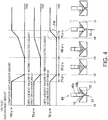
- Fig. 4 is an explanatory diagram showing the state change occurring until the fluent material 15 is discharged when applying the second drive waveform w2 to the first piezoelectric element 40a and applying the first drive waveform w1 to the second piezoelectric element 40b.
- the second piezoelectric element 40b expands first, and then the first piezoelectric element 40a expands. Even in such an operation, due to the rapid expansion of the first piezoelectric element 40a located on the back end side, the fluent material 15 is discharged from the discharge port 31.
- the operation shown in Fig. 3 and the operation shown in Fig. 4 are repeatedly performed alternately once for each term in the first piezoelectric element 40a and the second piezoelectric element 40b.
- the fluid ejection device 100 related to the present embodiment described hereinabove since the plurality of piezoelectric elements 40a, 40b is connected in series to each other, it is possible to increase the displacement amount of the moving object 20 without using the amplification mechanism. As a result, the size of the actuator 40 can be reduced. Further, since it is possible to output the second drive waveform w2 having the steep voltage change part PR to each of the first piezoelectric element 40a and the second piezoelectric element 40b, it is possible to prevent that the first piezoelectric element 40a alone is deteriorated. Therefore, the durability of the piezoelectric element 40a is improved.
- the tip part of the moving object 20 is made to come closer to the inner wall 32 on the periphery of the discharge port 31, and then the tip part of the moving object 20 is made to collide with the inner wall 32 using the steep voltage change part PR of the second drive waveform w2. Therefore, since it is possible to make the moving object 20 collide with the inner wall 32 at high speed while keeping the sufficient stroke amount for filling the chamber with the fluent material 15, it is possible to discharge the material high in viscosity.
- the output of the (voltage change part PR of the) second drive waveform w2 is started after outputting (and preferably finishing outputting) the (voltage change part of the) first drive waveform w1 to each of the piezoelectric elements 40a, 40b, it is possible to reduce the generation of the unwanted vibration in the actuator 40 compared to the case in which the first drive waveform w1 and a part of the second drive waveform w2 are output in an overlapping manner.
- the resonance frequencies of the first piezoelectric element 40a and the second piezoelectric element 40b are equal to each other, it is possible to make the first piezoelectric element 40a and the second piezoelectric element 40b perform the expansion and contraction actions substantially the same as each other. Therefore, the control of the expansion and contraction action of the actuator 40 becomes easy.
- the first drive waveform w1 to be output to the first piezoelectric element 40a and the first drive waveform w1 to be output to the second piezoelectric element 40b are the same as each other, and the second drive waveform w2 to be output to the first piezoelectric element 40a and the second drive waveform w2 to be output to the second piezoelectric element 40b are the same as each other, it is possible to use the drive waveforms common to the first piezoelectric element 40a and the second piezoelectric element 40b. Therefore, the control of the expansion and contraction action of the actuator 40 becomes easy.
- the durability of the piezoelectric elements 40a, 40b is improved.
- Fig. 5 is a schematic configuration diagram of a fluid ejection device 100A according to a second embodiment of the invention.
- the fluid ejection device 100A according to the present embodiment is different from the first embodiment in the point that the piezoelectric elements 40a, 40b are connected to each other via a contact part 90, and is the same as the first embodiment in the rest of the configuration.
- the fluid ejection device 100A is provided with the contact part 90 shaped like a true sphere.
- the end surfaces of the first piezoelectric element 40a and the second piezoelectric element 40b having contact with the contact part 90 are each recessed to form a tapered shape such as a cone. Therefore, the contact part 90 and each of the piezoelectric elements 40a, 40b have line contact with each other.
- the contact part 90 is a rigid body, and is formed of metal or ceramic.
- the first piezoelectric element 40a and the second piezoelectric element 40b are not required to be equal to each other in resonance frequency, expansion speed, or maximum displacement amount.
- the first drive waveform and the second drive waveform applied to the first piezoelectric element 40a, and the first drive waveform and the second drive waveform applied to the second piezoelectric element 40b can also be different drive waveforms from each other in accordance with the resonance frequencies, the expansion speeds, and the maximum displacement amounts of the respective piezoelectric elements so that the piezoelectric elements behave in the same way.
- the moving object 20 and the second piezoelectric element 40b can also be bonded with an adhesive without disposing the biasing member 80.
- the application operations shown in Fig. 3 and Fig. 4 can be switched alternately every time, or can also be switched after performing each of the application operations two or more times. Further, it is not required to make uniform the number of times of the operation shown in Fig. 3 and the number of times of the operation shown in Fig. 4 .
- each of the first piezoelectric element 40a and the second piezoelectric element 40b having contact with the contact part 90 it is also possible to use a flat surface or another surface as the end surface of each of the first piezoelectric element 40a and the second piezoelectric element 40b having contact with the contact part 90 to thereby make the contact part 90 and each of the piezoelectric elements 40a, 40b have point contact with each other. Further, it is also possible to make one have point contact with each other, and the other have line contact with each other.
- the invention is not limited to the embodiments and the modified examples described above, but can be implemented with a variety of configurations within the scope of the invention as defined by the claims.
- the technical features in the embodiments and the modified examples corresponding to the technical features in the aspects described in the SUMMARY section can arbitrarily be replaced or combined in order to solve the problems described above, or in order to achieve all or a part of the advantages described above.
- the technical feature can arbitrarily be eliminated unless described in the specification as an essential element.
Landscapes
- Particle Formation And Scattering Control In Inkjet Printers (AREA)
- Coating Apparatus (AREA)
Abstract
Description
- The present invention relates to a fluid ejection device.
- There has been known a fluid ejection device adapted to discharge to fly a droplet material using reciprocation of a moving object. In many cases, an actuator using a piezoelectric element or the like is used as a drive source for translating the moving object. Since the piezoelectric element can generate only a small amount of displacement, the amount of displacement is amplified via an amplification mechanism in the technology described in, for example,
JP-T-2014-525831 - However, if the amplification mechanism is used, the configuration becomes complicated, and there is a possibility of incurring growth in size of the drive device. Therefore, there has been desired a technology capable of providing a sufficient amount of displacement of a moving object without using the amplification mechanism in a fluid ejection device for discharging a droplet using reciprocation of the moving object.
- An advantage of some aspects of the invention is to solve at least a part of the problems described above, and the invention can be implemented as the following forms.
- (1) According to an aspect of the invention, a fluid ejection device is provided. The fluid ejection device is a fluid ejection device adapted to eject a fluent material, the fluid ejection device including a fluent material chamber supplied with the fluent material, a moving object, which can reciprocate in the fluent material chamber, a nozzle part having a discharge port communicating with the fluent material chamber, and an inner wall on a periphery of the discharge port on which a tip part of the moving object can contact from the fluent material chamber side, an actuator having contact with a back end part of the moving object to reciprocate the moving object to thereby discharge the fluent material from the discharge port, and a drive signal supply section adapted to output a signal used to drive the actuator, wherein the actuator includes a first piezoelectric element and a second piezoelectric element connected in series to each other, an end of the second piezoelectric element having contact (which may be indirect contact) with the back end part of the moving object, the drive signal supply section is capable of outputting a first drive waveform and a second drive waveform having a voltage change part steeper than a voltage change part included in the first drive waveform respectively to the first piezoelectric element and the second piezoelectric element, and the drive signal supply section outputs the second drive waveform to the second piezoelectric element in a case of outputting the first drive waveform to the first piezoelectric element, and outputs the first drive waveform to the second piezoelectric element in a case of outputting the second drive waveform to the first piezoelectric element. According to the fluid ejection device having such a configuration, since the actuator for reciprocating the moving object is formed of a plurality of piezoelectric elements connected in series to each other, the sufficient displacement amount of the moving object can be obtained without using an amplification mechanism. Further, since it is possible to output the second drive waveform having the steep voltage change part to each of the first piezoelectric element and the second piezoelectric element, it is possible to prevent that the first piezoelectric element alone is deteriorated. Therefore, the durability of the actuator is improved.
- (2) In the fluid ejection device according to the aspect of the invention, the drive signal supply section may make the tip part of the moving object come closer to the inner wall using at least a part of the first drive waveform, and the tip part of the moving object collide with the inner wall using the steeper voltage change part of the second drive waveform. According to such a configuration, since it is possible to make the moving object collide with the inner wall at high speed while keeping the sufficient stroke amount for filling the chamber with the fluent material, it is possible to discharge the material high in viscosity.
- (3) In the fluid ejection device according to the aspect of the invention, the drive signal supply section may start outputting the second drive waveform after outputting the first drive waveform with respect to each of the first piezoelectric element and the second piezoelectric element. According to such a configuration, it is possible to reduce the generation of the unwanted vibration in the actuator compared to the case in which the first drive waveform and a part of the second drive waveform are output in an overlapping manner.
- (4) In the fluid ejection device according to the aspect of the invention, that the drive signal supply section may be provided with a first drive signal supply section adapted to output the first drive waveform and the second drive waveform to the first piezoelectric element, and a second drive signal supply section adapted to output the first drive waveform and the second drive waveform to the second piezoelectric element. According to such a configuration, since it is possible to supply the drive signals individually to the first piezoelectric element and the second piezoelectric element, even if the first piezoelectric element and the second piezoelectric element are different in characteristics, it is possible to make the elements perform the expansion and contraction actions corresponding to the respective characteristics.
- (5) In the fluid ejection device according to the aspect of the invention, the first piezoelectric element and the second piezoelectric element may be equal in resonance frequency to each other. According to such a configuration, it is possible to make the first piezoelectric element and the second piezoelectric element perform substantially the same expansion and contraction action as each other. Therefore, the control of the expansion and contraction action of the actuator becomes easy.
- (6) In the fluid ejection device according to the aspect of the invention, the first drive waveform to be output to the first piezoelectric element and the first drive waveform to be output to the second piezoelectric element may be the same as each other, and the second drive waveform to be output to the first piezoelectric element and the second drive waveform to be output to the second piezoelectric element may be the same as each other. According to such a configuration, since it is possible to use the drive waveforms common to the first piezoelectric element and the second piezoelectric element, it becomes easy to control the expansion and contraction action of the actuator.
- (7) In the fluid ejection device according to the aspect of the invention, the piezoelectric elements as a plurality of piezoelectric elements may be connected to each other via a contact part, and the contact part may have one of point contact and line contact with each of the first piezoelectric element and the second piezoelectric element. According to such a configuration, since the mutual heat generation of the piezoelectric elements does not affect each other, the durability of the piezoelectric elements is improved.
- (8) The fluid ejection device according to the aspect of the invention may further include a biasing member adapted to bias the moving object in a direction from the discharge port toward the actuator. According to such a configuration, since the preliminary load can be applied by the biasing member to the piezoelectric elements, the durability of the piezoelectric elements is improved.
- It should be noted that the invention can be implemented in a variety of forms such as a fluid ejection system, or a method of ejecting a fluid.
- Embodiments of the invention will now be described by way of example only with reference to the accompanying drawings, wherein like numbers reference like elements.
-
Fig. 1 is a schematic configuration diagram of a fluid ejection system including a fluid ejection device according to a first embodiment of the invention. -
Fig. 2 is a diagram showing a schematic shape of a drive waveform. -
Fig. 3 is an explanatory diagram showing changes in state until a fluent material is discharged. -
Fig. 4 is an explanatory diagram showing changes in state until a fluent material is discharged. -
Fig. 5 is a schematic configuration diagram of a fluid ejection device according to a second embodiment. -
Fig. 1 is a schematic configuration diagram of afluid ejection system 200 including afluid ejection device 100 according to a first embodiment of the invention. Thefluid ejection device 100 is, for example, a device used for a printer, and a device for discharging a minute amount of a variety of fluent materials in a range from a fluent material low in viscosity such as water, a solvent, or a reagent to a fluent material high in viscosity such as a solder paste, a silver paste, or an adhesive at high speed irrespective of presence or absence of a filler. - The
fluid ejection system 200 is provided with thefluid ejection device 100, afluent material reservoir 11, aflow channel 12, a pressurizingsection 13, a drivesignal supply section 60, and acontrol section 70. Thefluid ejection device 100 is provided with afluent material chamber 10, a movingobject 20, anozzle part 30, anactuator 40, and abiasing member 80. It should be noted that thefluid ejection system 200 can also be figured out as (considered to be) a fluid ejection device in a broad sense. - In the
fluent material chamber 10, there is reserved a fluent material. Thefluent material chamber 10 is supplied with the fluent material from thefluent material reservoir 11 through theflow channel 12. The fluent material reserved in thefluent material reservoir 11 is pressurized by the pressurizingsection 13, and is thus supplied to theflow channel 12. In thefluent material chamber 10, there is disposed a tip part of themoving object 20 capable of reciprocating in thefluent material chamber 10. Further, on one side surface of thefluent material chamber 10, there is disposed thenozzle part 30 at a position opposed to the tip side of themoving object 20. - The
nozzle part 30 has adischarge port 31 communicating with thefluent material chamber 10. The tip part of themoving object 20 is capable of having contact with aninner wall 32 on the periphery of thedischarge port 31 from thefluent material chamber 10 side. Theinner wall 32 is tilted to form a tapered shape. Due to the collision of themoving object 20 to the part having the tapered shape, the fluent material in thefluent material chamber 10 is discharged from thenozzle part 30. - The
moving object 20 is, for example, a rod-like member having a tip shaped like a plane or a sphere, or having a tip provided with a projection. Themoving object 20 is provided with thebiasing member 80 in a back end part. Thebiasing member 80 biases themoving object 20 in a direction from thedischarge port 31 toward theactuator 40. More specifically, thebiasing member 80 is disposed so as to be sandwiched between aflange part 21 disposed on the back end part of themoving object 20 and awall surface 14 on theactuator 40 side of thefluent material chamber 10, and therefore, thebiasing member 80 biases themoving object 20 toward theactuator 40. Due to the biasing force by thebiasing member 80, a preliminary load is applied to the actuator 40 (a firstpiezoelectric element 40a, a secondpiezoelectric element 40b). In the present embodiment, thebiasing member 80 is formed of a compression coil spring. It should be noted that thebiasing member 80 can also be formed of a different elastic member such as a rubber spring. - The
actuator 40 is provided with the firstpiezoelectric element 40a and the secondpiezoelectric element 40b connected in series to each other. An end of the secondpiezoelectric element 40b has contact with the back end part of themoving object 20. An end part of the firstpiezoelectric element 40a located on an opposite side to the movingobject 20 side is fixed to ahousing 101 of thefluid ejection device 100. Theactuator 40 reciprocates the movingobject 20 to thereby discharge the fluent material from thedischarge port 31. - In the present embodiment, the first
piezoelectric element 40a and the secondpiezoelectric element 40b are each a piezoelectric element having a rod-like shape or a block-like shape expanding and contracting in the longitudinal direction. In the present embodiment, the firstpiezoelectric element 40a and the secondpiezoelectric element 40b are piezoelectric elements having the same characteristics. Specifically, the firstpiezoelectric element 40a and the secondpiezoelectric element 40b are the same in resonance frequency, expansion speed, and maximum amount of displacement. The firstpiezoelectric element 40a and the secondpiezoelectric element 40b are bonded to each other with an adhesive. As the adhesive, there can be used, for example, epoxy resin or acrylic adhesive. - A
signal amplifying section 50a is connected to the firstpiezoelectric element 40a, and asignal amplifying section 50b is connected to the secondpiezoelectric element 40b. The drivesignal supply section 60 is connected to thesignal amplifying sections control section 70. Thesignal amplifying sections piezoelectric elements signal amplifying sections - The drive
signal supply section 60 generates drive signals for driving theactuator 40. In the present embodiment, the drivesignal supply section 60 is provided with a first drivesignal supply section 60a and a second drivesignal supply section 60b. The first drivesignal supply section 60a generates the drive signal to be supplied to the firstpiezoelectric element 40a. The second drivesignal supply section 60b generates the drive signal to be supplied to the secondpiezoelectric element 40b. The drive signals generated by the drivesignal supply sections signal amplifying sections piezoelectric elements signal supply sections control section 70. -
Fig. 2 is a diagram showing schematic shapes of a first drive waveform w1 and a second drive waveform w2 output to the respectivepiezoelectric elements control section 70, the first drivesignal supply section 60a is capable of outputting the first drive waveform w1 and the second drive waveform w2 to the firstpiezoelectric element 40a, and the second drivesignal supply section 60b is capable of outputting the first drive waveform w1 and the second drive waveform w2 to the secondpiezoelectric element 40b. Further, the drivesignal supply section 60 outputs the second drive waveform w2 from the second drivesignal supply section 60b to the secondpiezoelectric element 40b in the case of outputting the first drive waveform w1 from the first drivesignal supply section 60a to the firstpiezoelectric element 40a, and outputs the first drive waveform w1 from the second drivesignal supply section 60b to the secondpiezoelectric element 40b in the case of outputting the second drive waveform w2 from the first drivesignal supply section 60a to the firstpiezoelectric element 40a. - Further, the drive
signal supply section 60 starts outputting the second drive waveform w2 after outputting the first drive waveform w1 with respect to each of the firstpiezoelectric element 40a and the secondpiezoelectric element 40b. Therefore, in the present embodiment, it results that the firstpiezoelectric element 40a and the secondpiezoelectric element 40b each have the first drive waveform w1 and the second drive waveform w2 alternately output to it. - In the present embodiment, the first drive waveform to be output to the first
piezoelectric element 40a and the first drive waveform to be output to the secondpiezoelectric element 40b are the same as each other, and the second drive waveform to be output to the firstpiezoelectric element 40a and the second drive waveform to be output to the secondpiezoelectric element 40b are the same as each other. The second drive waveform w2 has a voltage change part PR steeper than a voltage change part included in the first drive waveform w1. When the steep voltage change part PR is applied to the firstpiezoelectric element 40a or the secondpiezoelectric element 40b, the moving speed of the movingobject 20 is increased due to the rapid expansion of the firstpiezoelectric element 40a or the secondpiezoelectric element 40b, and thus, thefluent material 15 is discharged from thedischarge port 31. -
Fig. 3 is an explanatory diagram showing the state change occurring until thefluent material 15 is discharged when applying the first drive waveform w1 to the firstpiezoelectric element 40a and applying the second drive waveform w2 to the secondpiezoelectric element 40b. The horizontal axis of each of the graphs represents time (µs), and the vertical axis of the graphs represents the displacement amounts (µm) and the voltages of thepiezoelectric elements piezoelectric element 40a and the displacement amount of the secondpiezoelectric element 40b with each other. It should be noted that the drive waveforms are simplified on the assumption that the drive waveforms behave similarly to the displacement amounts of the respective piezoelectric elements. Further, in order to show the operation of thefluid ejection device 100 in a simplified manner, in the lower part of the drawing, there is shown a condition in which theactuator 40 has direct contact with thedischarge port 31 to discharge thefluent material 15. - The period from the timing t0 to the timing t1 corresponds to the state in which voltages are applied to both of the
piezoelectric elements piezoelectric elements piezoelectric element 40a and the secondpiezoelectric element 40b are contracted due to fall of both of the first drive waveform w1 and the second drive waveform w2. At the timing t2, the firstpiezoelectric element 40a and the secondpiezoelectric element 40b are contracted to the minimum. - In the period (50 µs) from the timing t2 to the timing t3, there is no variation in any of the drive waveforms w1, w2 and the first
piezoelectric element 40a and the secondpiezoelectric element 40b. In this period, thefluent material chamber 10 is filled with thefluent material 15 from thefluent material reservoir 11. - In the period (100 µs) from the timing t3 to the timing t4, the first
piezoelectric element 40a is expanded due to gradual rise of the first drive waveform w1. At the timing t4, the firstpiezoelectric element 40a expands to the maximum displacement amount, and then, the steep voltage change part PR of the second drive waveform w2 is applied to the secondpiezoelectric element 40b. - In the period (25 µs) from the timing t4 to the timing t5, the second
piezoelectric element 40b located on the tip side is rapidly expanded due to application of the steep voltage change part PR in the second drive waveform w2 to the secondpiezoelectric element 40b. Therefore, at the timing t5, the moving object 20 (not shown inFig. 3 ) thus accelerated collides with theinner wall 32, and thus, thefluent material 15 is discharged from thedischarge port 31. -
Fig. 4 is an explanatory diagram showing the state change occurring until thefluent material 15 is discharged when applying the second drive waveform w2 to the firstpiezoelectric element 40a and applying the first drive waveform w1 to the secondpiezoelectric element 40b. As shown inFig. 4 , in the case of applying the second drive waveform w2 to the firstpiezoelectric element 40a and applying the first drive waveform w1 to the secondpiezoelectric element 40b, the secondpiezoelectric element 40b expands first, and then the firstpiezoelectric element 40a expands. Even in such an operation, due to the rapid expansion of the firstpiezoelectric element 40a located on the back end side, thefluent material 15 is discharged from thedischarge port 31. - In the present embodiment, the operation shown in
Fig. 3 and the operation shown inFig. 4 are repeatedly performed alternately once for each term in the firstpiezoelectric element 40a and the secondpiezoelectric element 40b. - According to the
fluid ejection device 100 related to the present embodiment described hereinabove, since the plurality ofpiezoelectric elements object 20 without using the amplification mechanism. As a result, the size of theactuator 40 can be reduced. Further, since it is possible to output the second drive waveform w2 having the steep voltage change part PR to each of the firstpiezoelectric element 40a and the secondpiezoelectric element 40b, it is possible to prevent that the firstpiezoelectric element 40a alone is deteriorated. Therefore, the durability of thepiezoelectric element 40a is improved. - Further, in the present embodiment, due to the first drive waveform w1, the tip part of the moving
object 20 is made to come closer to theinner wall 32 on the periphery of thedischarge port 31, and then the tip part of the movingobject 20 is made to collide with theinner wall 32 using the steep voltage change part PR of the second drive waveform w2. Therefore, since it is possible to make the movingobject 20 collide with theinner wall 32 at high speed while keeping the sufficient stroke amount for filling the chamber with thefluent material 15, it is possible to discharge the material high in viscosity. - Further, in the present embodiment, since the output of the (voltage change part PR of the) second drive waveform w2 is started after outputting (and preferably finishing outputting) the (voltage change part of the) first drive waveform w1 to each of the
piezoelectric elements actuator 40 compared to the case in which the first drive waveform w1 and a part of the second drive waveform w2 are output in an overlapping manner. - Further, since in the present embodiment, it is possible to supply the drive signals individually from the drive
signal supply sections piezoelectric element 40a and the secondpiezoelectric element 40b, even if the firstpiezoelectric element 40a and the secondpiezoelectric element 40b are different in characteristics, it is possible to make the elements perform the expansion and contraction actions corresponding to the respective characteristics. - Further, in the present embodiment, since the resonance frequencies of the first
piezoelectric element 40a and the secondpiezoelectric element 40b are equal to each other, it is possible to make the firstpiezoelectric element 40a and the secondpiezoelectric element 40b perform the expansion and contraction actions substantially the same as each other. Therefore, the control of the expansion and contraction action of theactuator 40 becomes easy. - Further, in the present embodiment, since the first drive waveform w1 to be output to the first
piezoelectric element 40a and the first drive waveform w1 to be output to the secondpiezoelectric element 40b are the same as each other, and the second drive waveform w2 to be output to the firstpiezoelectric element 40a and the second drive waveform w2 to be output to the secondpiezoelectric element 40b are the same as each other, it is possible to use the drive waveforms common to the firstpiezoelectric element 40a and the secondpiezoelectric element 40b. Therefore, the control of the expansion and contraction action of theactuator 40 becomes easy. - Further, in the present embodiment, since the preliminary load is applied by the biasing
member 80 to thepiezoelectric elements piezoelectric elements -
Fig. 5 is a schematic configuration diagram of afluid ejection device 100A according to a second embodiment of the invention. Thefluid ejection device 100A according to the present embodiment is different from the first embodiment in the point that thepiezoelectric elements contact part 90, and is the same as the first embodiment in the rest of the configuration. - The
fluid ejection device 100A according to the present embodiment is provided with thecontact part 90 shaped like a true sphere. The end surfaces of the firstpiezoelectric element 40a and the secondpiezoelectric element 40b having contact with thecontact part 90 are each recessed to form a tapered shape such as a cone. Therefore, thecontact part 90 and each of thepiezoelectric elements contact part 90 is a rigid body, and is formed of metal or ceramic. - According to the
fluid ejection device 100 related to the present embodiment described hereinabove, since mutual heat generation of thepiezoelectric elements piezoelectric elements - In each of the embodiments described above, the first
piezoelectric element 40a and the secondpiezoelectric element 40b are not required to be equal to each other in resonance frequency, expansion speed, or maximum displacement amount. The first drive waveform and the second drive waveform applied to the firstpiezoelectric element 40a, and the first drive waveform and the second drive waveform applied to the secondpiezoelectric element 40b can also be different drive waveforms from each other in accordance with the resonance frequencies, the expansion speeds, and the maximum displacement amounts of the respective piezoelectric elements so that the piezoelectric elements behave in the same way. - In each of the embodiments described above, the moving
object 20 and the secondpiezoelectric element 40b can also be bonded with an adhesive without disposing the biasingmember 80. - In each of the embodiments described above, the application operations shown in
Fig. 3 andFig. 4 can be switched alternately every time, or can also be switched after performing each of the application operations two or more times. Further, it is not required to make uniform the number of times of the operation shown inFig. 3 and the number of times of the operation shown inFig. 4 . - In the second embodiment, it is also possible to use a flat surface or another surface as the end surface of each of the first
piezoelectric element 40a and the secondpiezoelectric element 40b having contact with thecontact part 90 to thereby make thecontact part 90 and each of thepiezoelectric elements - The invention is not limited to the embodiments and the modified examples described above, but can be implemented with a variety of configurations within the scope of the invention as defined by the claims. For example, the technical features in the embodiments and the modified examples corresponding to the technical features in the aspects described in the SUMMARY section can arbitrarily be replaced or combined in order to solve the problems described above, or in order to achieve all or a part of the advantages described above. Further, the technical feature can arbitrarily be eliminated unless described in the specification as an essential element.
Claims (8)
- A fluid ejection device (200) adapted to eject a fluent material comprising:a fluent material chamber (10) configured to be supplied with the fluent material;a moving object (20), which can reciprocate in the fluent material chamber;a nozzle part (30) having a discharge port (31) communicating with the fluent material chamber, and an inner wall (32) on a periphery of the discharge port on which a tip part of the moving object can contact from the fluent material chamber side;an actuator (40) having contact with a back end part of the moving object to reciprocate the moving object to thereby discharge the fluent material from the discharge port; anda drive signal supply section (60a, 60b) adapted to output a signal used to drive the actuator,wherein the actuator includes a first piezoelectric element (40a) and a second piezoelectric element (40b) connected in series to each other, an end of the second piezoelectric element having contact with the back end part of the moving object,the drive signal supply section is capable of outputting a first drive waveform (w1) and a second drive waveform (w2) having a voltage change part (PR) steeper than a voltage change part included in the first drive waveform to the first piezoelectric element and the second piezoelectric element, andthe drive signal supply section is configured to output the second drive waveform to the second piezoelectric element in a case of outputting the first drive waveform to the first piezoelectric element, and outputs the first drive waveform to the second piezoelectric element in a case of outputting the second drive waveform to the first piezoelectric element.
- The fluid ejection device according to Claim 1, wherein
the drive signal supply section is configured to makethe tip part of the moving object come closer to the inner wall using at least a part of the first drive waveform, andthe tip part of the moving object collide with the inner wall using the steeper voltage change part of the second drive waveform. - The fluid ejection device according to Claim 1 or Claim 2, wherein
the drive signal supply section is configured to start outputting the second drive waveform after outputting the first drive waveform with respect to each of the first piezoelectric element and the second piezoelectric element. - The fluid ejection device according to any one of the preceding claims, wherein
the drive signal supply section is provided with a first drive signal supply section (60a) adapted to output the first drive waveform and the second drive waveform to the first piezoelectric element, and a second drive signal supply section (60b) adapted to output the first drive waveform and the second drive waveform to the second piezoelectric element. - The fluid ejection device according to any one of the preceding claims, wherein
the first piezoelectric element and the second piezoelectric element are equal in resonance frequency to each other. - The fluid ejection device according to any one of the preceding claims, wherein
the first drive waveform to be output to the first piezoelectric element and the first drive waveform to be output to the second piezoelectric element are the same as each other, and
the second drive waveform to be output to the first piezoelectric element and the second drive waveform to be output to the second piezoelectric element are the same as each other. - The fluid ejection device according to any one of the preceding claims, wherein
the piezoelectric elements as a plurality of piezoelectric elements are connected to each other via a contact part (90), and
the contact part has one of point contact and line contact with each of the first piezoelectric element and the second piezoelectric element. - The fluid ejection device according to any one of the preceding claims, further comprising:a biasing member (80) adapted to bias the moving object in a direction from the discharge port toward the actuator.
Applications Claiming Priority (1)
| Application Number | Priority Date | Filing Date | Title |
|---|---|---|---|
| JP2016040814A JP6623846B2 (en) | 2016-03-03 | 2016-03-03 | Fluid ejection device |
Publications (2)
| Publication Number | Publication Date |
|---|---|
| EP3243662A1 true EP3243662A1 (en) | 2017-11-15 |
| EP3243662B1 EP3243662B1 (en) | 2019-04-17 |
Family
ID=58228041
Family Applications (1)
| Application Number | Title | Priority Date | Filing Date |
|---|---|---|---|
| EP17159251.2A Active EP3243662B1 (en) | 2016-03-03 | 2017-03-03 | Fluid ejection device |
Country Status (4)
| Country | Link |
|---|---|
| US (1) | US10144031B2 (en) |
| EP (1) | EP3243662B1 (en) |
| JP (1) | JP6623846B2 (en) |
| CN (1) | CN107149996B (en) |
Families Citing this family (4)
| Publication number | Priority date | Publication date | Assignee | Title |
|---|---|---|---|---|
| JP6707907B2 (en) | 2016-03-03 | 2020-06-10 | セイコーエプソン株式会社 | Fluid ejection device |
| CN107442313B (en) * | 2017-09-19 | 2019-08-02 | 深圳市华星光电技术有限公司 | A kind of spray equipment, paint finishing and spraying method |
| KR102663958B1 (en) | 2018-06-25 | 2024-05-09 | 노드슨 코포레이션 | System and method for controlling spray dispenser position |
| JP7820696B2 (en) * | 2022-03-03 | 2026-02-26 | 株式会社リコー | Drive control device, head unit, liquid ejection device |
Citations (2)
| Publication number | Priority date | Publication date | Assignee | Title |
|---|---|---|---|---|
| US20060256164A1 (en) * | 2005-05-13 | 2006-11-16 | Atsushi Hirota | An Inkjet Printer And A Method Of Manufacturing An Inkjet Printer |
| DE102011108799A1 (en) * | 2011-07-29 | 2013-01-31 | Vermes Microdispensing GmbH | Dosing system and dosing process |
Family Cites Families (12)
| Publication number | Priority date | Publication date | Assignee | Title |
|---|---|---|---|---|
| US4362407A (en) | 1981-09-08 | 1982-12-07 | Piezo Electric Products, Inc. | Piezoelectric printer and piezoelectric multilam actuator used therein |
| JPH04365384A (en) | 1991-06-13 | 1992-12-17 | Nec Corp | mechanical amplification mechanism |
| GB9616521D0 (en) | 1996-08-06 | 1996-09-25 | Lucas Ind Plc | Injector |
| DE19646511C1 (en) | 1996-11-12 | 1998-05-14 | Marco Systemanalyse Entw | Piezo actuator drive or adjustment element |
| US6902255B1 (en) | 1998-10-16 | 2005-06-07 | Silverbrook Research Pty Ltd | Inkjet printers |
| DE19918976A1 (en) * | 1999-04-27 | 2000-11-02 | Bosch Gmbh Robert | Fuel injector and method for actuating it |
| JP2002361862A (en) | 2001-06-01 | 2002-12-18 | Hitachi Koki Co Ltd | Inkjet print head |
| DE102005009147A1 (en) | 2005-03-01 | 2006-09-07 | Robert Bosch Gmbh | Fuel injector for internal combustion engines |
| KR101592443B1 (en) | 2007-05-18 | 2016-02-18 | 무사시 엔지니어링 가부시키가이샤 | Liquid material discharge method and apparatus |
| JP5334271B2 (en) * | 2011-06-03 | 2013-11-06 | 富士フイルム株式会社 | Liquid ejection head drive device, liquid ejection device, and ink jet recording apparatus |
| JP4907738B1 (en) * | 2011-06-14 | 2012-04-04 | 株式会社根本杏林堂 | Injection device and method for controlling ultrasonic motor |
| CN104549829B (en) * | 2014-12-16 | 2017-04-12 | 摩易国际股份有限公司 | Control and management method for intelligent atomizer |
-
2016
- 2016-03-03 JP JP2016040814A patent/JP6623846B2/en active Active
-
2017
- 2017-02-27 US US15/443,250 patent/US10144031B2/en active Active
- 2017-03-01 CN CN201710119600.3A patent/CN107149996B/en active Active
- 2017-03-03 EP EP17159251.2A patent/EP3243662B1/en active Active
Patent Citations (3)
| Publication number | Priority date | Publication date | Assignee | Title |
|---|---|---|---|---|
| US20060256164A1 (en) * | 2005-05-13 | 2006-11-16 | Atsushi Hirota | An Inkjet Printer And A Method Of Manufacturing An Inkjet Printer |
| DE102011108799A1 (en) * | 2011-07-29 | 2013-01-31 | Vermes Microdispensing GmbH | Dosing system and dosing process |
| JP2014525831A (en) | 2011-07-29 | 2014-10-02 | フェルメス マイクロディスペンシング ゲゼルシャフト ミット ベシュレンクテル ハフツンク | Dosing system and dosing method |
Also Published As
| Publication number | Publication date |
|---|---|
| US10144031B2 (en) | 2018-12-04 |
| CN107149996B (en) | 2021-02-26 |
| JP2017154099A (en) | 2017-09-07 |
| US20170252770A1 (en) | 2017-09-07 |
| CN107149996A (en) | 2017-09-12 |
| JP6623846B2 (en) | 2019-12-25 |
| EP3243662B1 (en) | 2019-04-17 |
Similar Documents
| Publication | Publication Date | Title |
|---|---|---|
| EP3243662B1 (en) | Fluid ejection device | |
| US12257625B2 (en) | Method and device for rapid three-dimensional workpiece from a molten material | |
| US12076782B2 (en) | Manufacturing of a three-dimensional workpiece from a liquid material | |
| JP5861405B2 (en) | Inkjet recording device | |
| JP5458808B2 (en) | Inkjet recording apparatus and inkjet recording method | |
| CN106457824A (en) | Inkjet head driving method and inkjet printing apparatus | |
| US11173706B2 (en) | Droplet discharge head | |
| JP2011037257A (en) | Device and method for discharging liquid | |
| JP6575534B2 (en) | Droplet discharge head driving method and droplet discharge apparatus | |
| CN113226569B (en) | Method and related system for controlling an injector | |
| CN104174549B (en) | liquid dispensing device | |
| EP3225396B1 (en) | Fluid ejection device | |
| CN110461608A (en) | droplet ejection device | |
| JP3884443B2 (en) | Liquid dispensing apparatus, liquid dispensing method, and liquid discharge head | |
| JP4492131B2 (en) | Droplet discharge head driving method and droplet discharge apparatus | |
| JP3522267B2 (en) | Recording method using ink jet recording apparatus and recording head suitable for the recording method | |
| US20250303704A1 (en) | Liquid discharge device and liquid discharge head | |
| US20250303703A1 (en) | Liquid discharge device and liquid discharge head | |
| US20250303692A1 (en) | Liquid discharge device and liquid discharge head | |
| JP5947865B2 (en) | Valve for metering of filled and pasty media | |
| JP2009074463A (en) | Control method for micro pump and drive circuit for micro pump | |
| JP2015214157A (en) | Ink jet recording device | |
| JP2014184315A (en) | Block of injection unit for liquid injection device, injection unit for liquid injection device, and surgical instrument |
Legal Events
| Date | Code | Title | Description |
|---|---|---|---|
| PUAI | Public reference made under article 153(3) epc to a published international application that has entered the european phase |
Free format text: ORIGINAL CODE: 0009012 |
|
| STAA | Information on the status of an ep patent application or granted ep patent |
Free format text: STATUS: THE APPLICATION HAS BEEN PUBLISHED |
|
| AK | Designated contracting states |
Kind code of ref document: A1 Designated state(s): AL AT BE BG CH CY CZ DE DK EE ES FI FR GB GR HR HU IE IS IT LI LT LU LV MC MK MT NL NO PL PT RO RS SE SI SK SM TR |
|
| AX | Request for extension of the european patent |
Extension state: BA ME |
|
| STAA | Information on the status of an ep patent application or granted ep patent |
Free format text: STATUS: REQUEST FOR EXAMINATION WAS MADE |
|
| 17P | Request for examination filed |
Effective date: 20180425 |
|
| RBV | Designated contracting states (corrected) |
Designated state(s): AL AT BE BG CH CY CZ DE DK EE ES FI FR GB GR HR HU IE IS IT LI LT LU LV MC MK MT NL NO PL PT RO RS SE SI SK SM TR |
|
| GRAP | Despatch of communication of intention to grant a patent |
Free format text: ORIGINAL CODE: EPIDOSNIGR1 |
|
| STAA | Information on the status of an ep patent application or granted ep patent |
Free format text: STATUS: GRANT OF PATENT IS INTENDED |
|
| INTG | Intention to grant announced |
Effective date: 20180927 |
|
| GRAS | Grant fee paid |
Free format text: ORIGINAL CODE: EPIDOSNIGR3 |
|
| GRAA | (expected) grant |
Free format text: ORIGINAL CODE: 0009210 |
|
| STAA | Information on the status of an ep patent application or granted ep patent |
Free format text: STATUS: THE PATENT HAS BEEN GRANTED |
|
| AK | Designated contracting states |
Kind code of ref document: B1 Designated state(s): AL AT BE BG CH CY CZ DE DK EE ES FI FR GB GR HR HU IE IS IT LI LT LU LV MC MK MT NL NO PL PT RO RS SE SI SK SM TR |
|
| REG | Reference to a national code |
Ref country code: GB Ref legal event code: FG4D |
|
| REG | Reference to a national code |
Ref country code: CH Ref legal event code: EP |
|
| REG | Reference to a national code |
Ref country code: DE Ref legal event code: R096 Ref document number: 602017003272 Country of ref document: DE |
|
| REG | Reference to a national code |
Ref country code: AT Ref legal event code: REF Ref document number: 1121101 Country of ref document: AT Kind code of ref document: T Effective date: 20190515 Ref country code: IE Ref legal event code: FG4D |
|
| REG | Reference to a national code |
Ref country code: NL Ref legal event code: MP Effective date: 20190417 |
|
| REG | Reference to a national code |
Ref country code: LT Ref legal event code: MG4D |
|
| PG25 | Lapsed in a contracting state [announced via postgrant information from national office to epo] |
Ref country code: NL Free format text: LAPSE BECAUSE OF FAILURE TO SUBMIT A TRANSLATION OF THE DESCRIPTION OR TO PAY THE FEE WITHIN THE PRESCRIBED TIME-LIMIT Effective date: 20190417 |
|
| PG25 | Lapsed in a contracting state [announced via postgrant information from national office to epo] |
Ref country code: PT Free format text: LAPSE BECAUSE OF FAILURE TO SUBMIT A TRANSLATION OF THE DESCRIPTION OR TO PAY THE FEE WITHIN THE PRESCRIBED TIME-LIMIT Effective date: 20190817 Ref country code: AL Free format text: LAPSE BECAUSE OF FAILURE TO SUBMIT A TRANSLATION OF THE DESCRIPTION OR TO PAY THE FEE WITHIN THE PRESCRIBED TIME-LIMIT Effective date: 20190417 Ref country code: ES Free format text: LAPSE BECAUSE OF FAILURE TO SUBMIT A TRANSLATION OF THE DESCRIPTION OR TO PAY THE FEE WITHIN THE PRESCRIBED TIME-LIMIT Effective date: 20190417 Ref country code: NO Free format text: LAPSE BECAUSE OF FAILURE TO SUBMIT A TRANSLATION OF THE DESCRIPTION OR TO PAY THE FEE WITHIN THE PRESCRIBED TIME-LIMIT Effective date: 20190717 Ref country code: FI Free format text: LAPSE BECAUSE OF FAILURE TO SUBMIT A TRANSLATION OF THE DESCRIPTION OR TO PAY THE FEE WITHIN THE PRESCRIBED TIME-LIMIT Effective date: 20190417 Ref country code: LT Free format text: LAPSE BECAUSE OF FAILURE TO SUBMIT A TRANSLATION OF THE DESCRIPTION OR TO PAY THE FEE WITHIN THE PRESCRIBED TIME-LIMIT Effective date: 20190417 Ref country code: SE Free format text: LAPSE BECAUSE OF FAILURE TO SUBMIT A TRANSLATION OF THE DESCRIPTION OR TO PAY THE FEE WITHIN THE PRESCRIBED TIME-LIMIT Effective date: 20190417 Ref country code: HR Free format text: LAPSE BECAUSE OF FAILURE TO SUBMIT A TRANSLATION OF THE DESCRIPTION OR TO PAY THE FEE WITHIN THE PRESCRIBED TIME-LIMIT Effective date: 20190417 |
|
| PG25 | Lapsed in a contracting state [announced via postgrant information from national office to epo] |
Ref country code: RS Free format text: LAPSE BECAUSE OF FAILURE TO SUBMIT A TRANSLATION OF THE DESCRIPTION OR TO PAY THE FEE WITHIN THE PRESCRIBED TIME-LIMIT Effective date: 20190417 Ref country code: PL Free format text: LAPSE BECAUSE OF FAILURE TO SUBMIT A TRANSLATION OF THE DESCRIPTION OR TO PAY THE FEE WITHIN THE PRESCRIBED TIME-LIMIT Effective date: 20190417 Ref country code: LV Free format text: LAPSE BECAUSE OF FAILURE TO SUBMIT A TRANSLATION OF THE DESCRIPTION OR TO PAY THE FEE WITHIN THE PRESCRIBED TIME-LIMIT Effective date: 20190417 Ref country code: GR Free format text: LAPSE BECAUSE OF FAILURE TO SUBMIT A TRANSLATION OF THE DESCRIPTION OR TO PAY THE FEE WITHIN THE PRESCRIBED TIME-LIMIT Effective date: 20190718 Ref country code: BG Free format text: LAPSE BECAUSE OF FAILURE TO SUBMIT A TRANSLATION OF THE DESCRIPTION OR TO PAY THE FEE WITHIN THE PRESCRIBED TIME-LIMIT Effective date: 20190717 |
|
| REG | Reference to a national code |
Ref country code: AT Ref legal event code: MK05 Ref document number: 1121101 Country of ref document: AT Kind code of ref document: T Effective date: 20190417 |
|
| PG25 | Lapsed in a contracting state [announced via postgrant information from national office to epo] |
Ref country code: IS Free format text: LAPSE BECAUSE OF FAILURE TO SUBMIT A TRANSLATION OF THE DESCRIPTION OR TO PAY THE FEE WITHIN THE PRESCRIBED TIME-LIMIT Effective date: 20190817 |
|
| REG | Reference to a national code |
Ref country code: DE Ref legal event code: R097 Ref document number: 602017003272 Country of ref document: DE |
|
| PG25 | Lapsed in a contracting state [announced via postgrant information from national office to epo] |
Ref country code: AT Free format text: LAPSE BECAUSE OF FAILURE TO SUBMIT A TRANSLATION OF THE DESCRIPTION OR TO PAY THE FEE WITHIN THE PRESCRIBED TIME-LIMIT Effective date: 20190417 Ref country code: RO Free format text: LAPSE BECAUSE OF FAILURE TO SUBMIT A TRANSLATION OF THE DESCRIPTION OR TO PAY THE FEE WITHIN THE PRESCRIBED TIME-LIMIT Effective date: 20190417 Ref country code: CZ Free format text: LAPSE BECAUSE OF FAILURE TO SUBMIT A TRANSLATION OF THE DESCRIPTION OR TO PAY THE FEE WITHIN THE PRESCRIBED TIME-LIMIT Effective date: 20190417 Ref country code: SK Free format text: LAPSE BECAUSE OF FAILURE TO SUBMIT A TRANSLATION OF THE DESCRIPTION OR TO PAY THE FEE WITHIN THE PRESCRIBED TIME-LIMIT Effective date: 20190417 Ref country code: EE Free format text: LAPSE BECAUSE OF FAILURE TO SUBMIT A TRANSLATION OF THE DESCRIPTION OR TO PAY THE FEE WITHIN THE PRESCRIBED TIME-LIMIT Effective date: 20190417 Ref country code: DK Free format text: LAPSE BECAUSE OF FAILURE TO SUBMIT A TRANSLATION OF THE DESCRIPTION OR TO PAY THE FEE WITHIN THE PRESCRIBED TIME-LIMIT Effective date: 20190417 |
|
| PLBE | No opposition filed within time limit |
Free format text: ORIGINAL CODE: 0009261 |
|
| STAA | Information on the status of an ep patent application or granted ep patent |
Free format text: STATUS: NO OPPOSITION FILED WITHIN TIME LIMIT |
|
| PG25 | Lapsed in a contracting state [announced via postgrant information from national office to epo] |
Ref country code: SM Free format text: LAPSE BECAUSE OF FAILURE TO SUBMIT A TRANSLATION OF THE DESCRIPTION OR TO PAY THE FEE WITHIN THE PRESCRIBED TIME-LIMIT Effective date: 20190417 Ref country code: IT Free format text: LAPSE BECAUSE OF FAILURE TO SUBMIT A TRANSLATION OF THE DESCRIPTION OR TO PAY THE FEE WITHIN THE PRESCRIBED TIME-LIMIT Effective date: 20190417 |
|
| 26N | No opposition filed |
Effective date: 20200120 |
|
| PG25 | Lapsed in a contracting state [announced via postgrant information from national office to epo] |
Ref country code: TR Free format text: LAPSE BECAUSE OF FAILURE TO SUBMIT A TRANSLATION OF THE DESCRIPTION OR TO PAY THE FEE WITHIN THE PRESCRIBED TIME-LIMIT Effective date: 20190417 |
|
| PG25 | Lapsed in a contracting state [announced via postgrant information from national office to epo] |
Ref country code: SI Free format text: LAPSE BECAUSE OF FAILURE TO SUBMIT A TRANSLATION OF THE DESCRIPTION OR TO PAY THE FEE WITHIN THE PRESCRIBED TIME-LIMIT Effective date: 20190417 |
|
| PG25 | Lapsed in a contracting state [announced via postgrant information from national office to epo] |
Ref country code: MC Free format text: LAPSE BECAUSE OF FAILURE TO SUBMIT A TRANSLATION OF THE DESCRIPTION OR TO PAY THE FEE WITHIN THE PRESCRIBED TIME-LIMIT Effective date: 20190417 |
|
| REG | Reference to a national code |
Ref country code: CH Ref legal event code: PL |
|
| REG | Reference to a national code |
Ref country code: BE Ref legal event code: MM Effective date: 20200331 |
|
| PG25 | Lapsed in a contracting state [announced via postgrant information from national office to epo] |
Ref country code: LU Free format text: LAPSE BECAUSE OF NON-PAYMENT OF DUE FEES Effective date: 20200303 |
|
| PG25 | Lapsed in a contracting state [announced via postgrant information from national office to epo] |
Ref country code: CH Free format text: LAPSE BECAUSE OF NON-PAYMENT OF DUE FEES Effective date: 20200331 Ref country code: IE Free format text: LAPSE BECAUSE OF NON-PAYMENT OF DUE FEES Effective date: 20200303 Ref country code: LI Free format text: LAPSE BECAUSE OF NON-PAYMENT OF DUE FEES Effective date: 20200331 |
|
| PG25 | Lapsed in a contracting state [announced via postgrant information from national office to epo] |
Ref country code: BE Free format text: LAPSE BECAUSE OF NON-PAYMENT OF DUE FEES Effective date: 20200331 |
|
| PG25 | Lapsed in a contracting state [announced via postgrant information from national office to epo] |
Ref country code: MT Free format text: LAPSE BECAUSE OF FAILURE TO SUBMIT A TRANSLATION OF THE DESCRIPTION OR TO PAY THE FEE WITHIN THE PRESCRIBED TIME-LIMIT Effective date: 20190417 Ref country code: CY Free format text: LAPSE BECAUSE OF FAILURE TO SUBMIT A TRANSLATION OF THE DESCRIPTION OR TO PAY THE FEE WITHIN THE PRESCRIBED TIME-LIMIT Effective date: 20190417 |
|
| PG25 | Lapsed in a contracting state [announced via postgrant information from national office to epo] |
Ref country code: MK Free format text: LAPSE BECAUSE OF FAILURE TO SUBMIT A TRANSLATION OF THE DESCRIPTION OR TO PAY THE FEE WITHIN THE PRESCRIBED TIME-LIMIT Effective date: 20190417 |
|
| PGFP | Annual fee paid to national office [announced via postgrant information from national office to epo] |
Ref country code: GB Payment date: 20260202 Year of fee payment: 10 |
|
| PGFP | Annual fee paid to national office [announced via postgrant information from national office to epo] |
Ref country code: DE Payment date: 20260128 Year of fee payment: 10 |
|
| PGFP | Annual fee paid to national office [announced via postgrant information from national office to epo] |
Ref country code: FR Payment date: 20260209 Year of fee payment: 10 |