JP5458808B2 - Inkjet recording apparatus and inkjet recording method - Google Patents
Inkjet recording apparatus and inkjet recording method Download PDFInfo
- Publication number
- JP5458808B2 JP5458808B2 JP2009251786A JP2009251786A JP5458808B2 JP 5458808 B2 JP5458808 B2 JP 5458808B2 JP 2009251786 A JP2009251786 A JP 2009251786A JP 2009251786 A JP2009251786 A JP 2009251786A JP 5458808 B2 JP5458808 B2 JP 5458808B2
- Authority
- JP
- Japan
- Prior art keywords
- pulse
- pressure chamber
- ink
- preliminary
- pressure
- Prior art date
- Legal status (The legal status is an assumption and is not a legal conclusion. Google has not performed a legal analysis and makes no representation as to the accuracy of the status listed.)
- Expired - Fee Related
Links
Images


Classifications
-
- B—PERFORMING OPERATIONS; TRANSPORTING
- B41—PRINTING; LINING MACHINES; TYPEWRITERS; STAMPS
- B41J—TYPEWRITERS; SELECTIVE PRINTING MECHANISMS, i.e. MECHANISMS PRINTING OTHERWISE THAN FROM A FORME; CORRECTION OF TYPOGRAPHICAL ERRORS
- B41J2/00—Typewriters or selective printing mechanisms characterised by the printing or marking process for which they are designed
- B41J2/005—Typewriters or selective printing mechanisms characterised by the printing or marking process for which they are designed characterised by bringing liquid or particles selectively into contact with a printing material
- B41J2/01—Ink jet
- B41J2/015—Ink jet characterised by the jet generation process
- B41J2/04—Ink jet characterised by the jet generation process generating single droplets or particles on demand
- B41J2/045—Ink jet characterised by the jet generation process generating single droplets or particles on demand by pressure, e.g. electromechanical transducers
- B41J2/04501—Control methods or devices therefor, e.g. driver circuits, control circuits
- B41J2/04596—Non-ejecting pulses
-
- B—PERFORMING OPERATIONS; TRANSPORTING
- B41—PRINTING; LINING MACHINES; TYPEWRITERS; STAMPS
- B41J—TYPEWRITERS; SELECTIVE PRINTING MECHANISMS, i.e. MECHANISMS PRINTING OTHERWISE THAN FROM A FORME; CORRECTION OF TYPOGRAPHICAL ERRORS
- B41J2/00—Typewriters or selective printing mechanisms characterised by the printing or marking process for which they are designed
- B41J2/005—Typewriters or selective printing mechanisms characterised by the printing or marking process for which they are designed characterised by bringing liquid or particles selectively into contact with a printing material
- B41J2/01—Ink jet
- B41J2/015—Ink jet characterised by the jet generation process
- B41J2/04—Ink jet characterised by the jet generation process generating single droplets or particles on demand
- B41J2/045—Ink jet characterised by the jet generation process generating single droplets or particles on demand by pressure, e.g. electromechanical transducers
- B41J2/04501—Control methods or devices therefor, e.g. driver circuits, control circuits
- B41J2/04543—Block driving
-
- B—PERFORMING OPERATIONS; TRANSPORTING
- B41—PRINTING; LINING MACHINES; TYPEWRITERS; STAMPS
- B41J—TYPEWRITERS; SELECTIVE PRINTING MECHANISMS, i.e. MECHANISMS PRINTING OTHERWISE THAN FROM A FORME; CORRECTION OF TYPOGRAPHICAL ERRORS
- B41J2/00—Typewriters or selective printing mechanisms characterised by the printing or marking process for which they are designed
- B41J2/005—Typewriters or selective printing mechanisms characterised by the printing or marking process for which they are designed characterised by bringing liquid or particles selectively into contact with a printing material
- B41J2/01—Ink jet
- B41J2/015—Ink jet characterised by the jet generation process
- B41J2/04—Ink jet characterised by the jet generation process generating single droplets or particles on demand
- B41J2/045—Ink jet characterised by the jet generation process generating single droplets or particles on demand by pressure, e.g. electromechanical transducers
- B41J2/04501—Control methods or devices therefor, e.g. driver circuits, control circuits
- B41J2/04581—Control methods or devices therefor, e.g. driver circuits, control circuits controlling heads based on piezoelectric elements
-
- B—PERFORMING OPERATIONS; TRANSPORTING
- B41—PRINTING; LINING MACHINES; TYPEWRITERS; STAMPS
- B41J—TYPEWRITERS; SELECTIVE PRINTING MECHANISMS, i.e. MECHANISMS PRINTING OTHERWISE THAN FROM A FORME; CORRECTION OF TYPOGRAPHICAL ERRORS
- B41J2/00—Typewriters or selective printing mechanisms characterised by the printing or marking process for which they are designed
- B41J2/005—Typewriters or selective printing mechanisms characterised by the printing or marking process for which they are designed characterised by bringing liquid or particles selectively into contact with a printing material
- B41J2/01—Ink jet
- B41J2/015—Ink jet characterised by the jet generation process
- B41J2/04—Ink jet characterised by the jet generation process generating single droplets or particles on demand
- B41J2/045—Ink jet characterised by the jet generation process generating single droplets or particles on demand by pressure, e.g. electromechanical transducers
- B41J2/04501—Control methods or devices therefor, e.g. driver circuits, control circuits
- B41J2/04588—Control methods or devices therefor, e.g. driver circuits, control circuits using a specific waveform
-
- B—PERFORMING OPERATIONS; TRANSPORTING
- B41—PRINTING; LINING MACHINES; TYPEWRITERS; STAMPS
- B41J—TYPEWRITERS; SELECTIVE PRINTING MECHANISMS, i.e. MECHANISMS PRINTING OTHERWISE THAN FROM A FORME; CORRECTION OF TYPOGRAPHICAL ERRORS
- B41J2202/00—Embodiments of or processes related to ink-jet or thermal heads
- B41J2202/01—Embodiments of or processes related to ink-jet heads
- B41J2202/10—Finger type piezoelectric elements
Abstract
Description
本発明は、インクジェット記録装置及びインクジェット記録方法に関するものである。 The present invention relates to an ink jet recording apparatus and an ink jet recording method.
インクジェット記録装置では、高品位の記録を実現するには記録ドット径を小さくする必要がある。記録ドット径を小さくする方法として、従来から、ノズル開口に連通する圧力室を膨張させてから収縮させるという、「引き打ち」方式を用いることが知られている(特許文献1、2参照)。この方式によれば、インク滴の質量を少なくできるので、記録ドット径を小さくすることが可能である。
In the ink jet recording apparatus, it is necessary to reduce the recording dot diameter in order to realize high quality recording. As a method for reducing the recording dot diameter, it is conventionally known to use a “pulling” method in which a pressure chamber communicating with a nozzle opening is expanded and then contracted (see
特許文献1、2では、収縮パルスによりインクメニスカスを一度押し出した後、「引き打ち」方式によりノズル内の奥深くに引き込んでから吐出する方法が開示されている。
また、圧力発生手段としての圧電素子を使用した記録ヘッドには、特許文献1に記載されている振動板を使用する方式(例えば積層ピエゾ方式、撓みモード方式)と、特許文献2に記載されている振動板を使用せずに圧力室の隔壁をせん断変形させるせん断モード方式とがある。
In addition, a recording head using a piezoelectric element as a pressure generating means includes a method using a diaphragm described in Patent Document 1 (for example, a laminated piezo method, a flexure mode method) and a method described in
特許文献1及び2に記載の駆動信号は、メニスカスを押し出す収縮パルスにスロープ波形を使用するためにアナログ回路が必要となり、駆動回路構成が複雑化する。また、駆動周期が長くなるため駆動周波数を高くすることができない。
The drive signals described in
また、特許文献1に記載されている振動板を介して圧力室の容積を変化させる積層ピエゾ方式は、圧電素子を圧力室の外に設けるため圧電素子の形状や大きさに余り制限を受けず、強力な素子を使用して強い圧力を発生させることが可能で、インク滴の吐出性や吐出制御性に優れる。しかし、構造が複雑になるので、大きなヘッドの製造は難しく、100チャネル程度が限度である。
Further, in the laminated piezo method in which the volume of the pressure chamber is changed via the diaphragm described in
一方、特許文献2に記載されているせん断モード方式のヘッドは、圧電素子に圧力室となる溝を掘り込んだ簡単な構造なので、数百チャネル持つ大きなヘッドを製造することが可能である。しかし、特にせん断モード方式の記録ヘッドに矩形波の駆動信号を用いると、圧力室内の圧力波振動の影響により微小液滴を吐出するのは困難である。
On the other hand, since the shear mode type head described in
圧力発生手段としての圧電素子を使用した記録ヘッド、特にせん断モード方式の記録ヘッドにおいて、メニスカスを押し出す収縮パルスに矩形波を使用して圧力波の発生を抑えながら吐出前のメニスカス位置を効果的に引き込んで微小液滴を吐出するためには、駆動方法に工夫が必要になる。 In a recording head using a piezoelectric element as a pressure generating means, especially a shear mode type recording head, a rectangular wave is used for the contraction pulse that pushes out the meniscus, and the meniscus position before ejection is effectively controlled while suppressing the generation of the pressure wave. In order to pull in and discharge microdroplets, it is necessary to devise a driving method.
そこで、本発明の課題は、駆動回路の簡素化を図ることが可能な矩形波の駆動信号を用いて、安定した小液滴吐出を可能とする記録ヘッドを備えるインクジェット記録装置及びインクジェット記録方法を提供することである。 Accordingly, an object of the present invention is to provide an ink jet recording apparatus and an ink jet recording method including a recording head that can stably discharge a small droplet by using a rectangular wave driving signal capable of simplifying a driving circuit. Is to provide.
上記課題は、以下の構成により解決される。 The above problem is solved by the following configuration.
1.圧力室と圧力室の容積を変化させる圧力発生手段とを有し、該圧力発生手段を駆動することにより圧力室内のインクをインク滴としてノズルから吐出せしめる記録ヘッドを備えるインクジェット記録装置において、
インク滴を吐出させるために圧力発生手段に印加する駆動信号が、圧力室の容積を収縮させた後に膨張させる予備パルスと、該予備パルスの直後に印加されるとともに圧力室の容積を膨張させた後に収縮させる第1のパルスを有する吐出パルスと、を含み、
前記第1のパルスの始端が前記予備パルスの終端に直接接続されていて、
前記予備パルスはパルス幅が2AL(ALは圧力室における圧力波の音響的共振周期の1/2)以上の矩形波であることを特徴とするインクジェット記録装置。
1. In an inkjet recording apparatus comprising a pressure head and a pressure generating means for changing the volume of the pressure chamber, and having a recording head that discharges ink in the pressure chamber as ink droplets from a nozzle by driving the pressure generating means.
A drive signal applied to the pressure generating means for ejecting the ink droplets is applied after the volume of the pressure chamber is contracted and expanded, and immediately after the preliminary pulse , the volume of the pressure chamber is expanded. An ejection pulse having a first pulse to be subsequently contracted,
The beginning of the first pulse is directly connected to the end of the preliminary pulse;
2. The ink jet recording apparatus according to
2.前記予備パルスのパルス幅が3.5AL以上、6AL以下であることを特徴とする1に記載のインクジェット記録装置。 2. 2. The ink jet recording apparatus according to 1, wherein a pulse width of the preliminary pulse is 3.5 AL or more and 6 AL or less.
3.前記予備パルスのパルス幅が3.5AL以上、4.5AL以下であることを特徴とする2に記載のインクジェット記録装置。 3. 3. The ink jet recording apparatus according to 2, wherein a pulse width of the preliminary pulse is 3.5 AL or more and 4.5 AL or less.
4.前記吐出パルスは、前記第1のパルスから1AL時間後に、前記圧力室の容積を収縮させた後に膨張させる第2のパルスを更に有することを特徴とする1〜3のいずれか1項に記載のインクジェット記録装置。
4). 4. The discharge pulse according to
5.前記第1のパルスの駆動電圧をVon、前記予備パルスの駆動電圧をVoffとしたとき、|Von|>|Voff|であることを特徴とする1〜4のいずれか1項に記載のインクジェット記録装置。
5. The inkjet recording according to any one of
6.|Von|/|Voff|=2であることを特徴とする5に記載のインクジェット記録装置。 6). 6. The ink jet recording apparatus according to 5, wherein | Von | / | Voff | = 2.
7.前記第2のパルスの駆動電圧が前記予備パルスの駆動電圧Voffと同電圧であることを特徴とする4〜6のいずれか1項に記載のインクジェット記録装置。
7). The inkjet recording apparatus according to any one of
8.インク滴を吐出しない時に、圧力室の圧力発生手段に対して前記予備パルスと前記第2のパルスの何れか一方のみ、あるいは、両方を印加してノズル内のインクメニスカスをノズルからインク滴を吐出させない程度に微振動させることを特徴とする4〜7のいずれか1項に記載のインクジェット記録装置。 8). When ink droplets are not ejected, only one or both of the preliminary pulse and the second pulse are applied to the pressure generating means of the pressure chamber, and the ink meniscus in the nozzle is ejected from the nozzle. 8. The ink jet recording apparatus according to any one of 4 to 7, wherein the ink jet recording apparatus is slightly vibrated to such an extent that it does not occur.
9.画像記録領域内でインク滴を吐出しない圧力室の圧力発生手段に対して前記予備パルスと前記第2のパルスの何れか一方のみ、あるいは、両方を印加してノズル内のインクメニスカスをノズルからインク滴を吐出させない程度に微振動させることを特徴とする8に記載のインクジェット記録装置。 9. Only one or both of the preliminary pulse and the second pulse are applied to the pressure generating means of the pressure chamber that does not eject ink droplets in the image recording area, and the ink meniscus in the nozzle is ejected from the nozzle. 9. The ink jet recording apparatus according to 8, wherein the ink jet recording apparatus is vibrated to such an extent that droplets are not discharged.
10.前記第1のパルスのパルス幅が1ALであることを特徴とする1〜9のいずれか1項に記載のインクジェット記録装置。 10. 10. The inkjet recording apparatus according to any one of 1 to 9, wherein a pulse width of the first pulse is 1AL.
11.前記圧力発生手段である圧電素子が隣接する圧力室の隔壁の少なくとも一部を形成し、且つせん断モードで変形する圧電素子であることを特徴とする1〜10のいずれか1項に記載のインクジェット記録装置。
11. 11. The inkjet according to
12.圧力室と圧力室の容積を変化させる圧力発生手段とを有し、該圧力発生手段を駆動することにより圧力室内のインクをインク滴としてノズルから吐出せしめる記録ヘッドを用いたインクジェット記録方法であって、
圧力室の容積を収縮させた後に膨張させる予備パルスと、該予備パルスの直後に印加されるとともに圧力室の容積を膨張させた後に収縮させる第1のパルスを有する吐出パルスと、を含む駆動信号を圧力発生手段に印加してインク滴を吐出させる工程を有し、
前記第1のパルスの始端が前記予備パルスの終端に直接接続されていて、
前記予備パルスはパルス幅が2AL(ALは圧力室における圧力波の音響的共振周期の1/2)以上の矩形波であることを特徴とするインクジェット記録方法。
12 An ink jet recording method using a recording head having a pressure chamber and pressure generating means for changing the volume of the pressure chamber, and discharging the ink in the pressure chamber as ink droplets from a nozzle by driving the pressure generating means. ,
A drive signal including a preliminary pulse that expands after the volume of the pressure chamber is contracted, and a discharge pulse that is applied immediately after the preliminary pulse and has a first pulse that contracts after the volume of the pressure chamber is expanded Applying a pressure to the pressure generating means to eject ink droplets,
The beginning of the first pulse is directly connected to the end of the preliminary pulse;
2. The ink jet recording method according to
13.前記予備パルスのパルス幅が3.5AL以上、6AL以下であることを特徴とする12に記載のインクジェット記録方法。 13. 13. The ink jet recording method according to 12, wherein a pulse width of the preliminary pulse is 3.5 AL or more and 6 AL or less.
14.前記予備パルスのパルス幅が3.5AL以上、4.5AL以下であることを特徴とする13に記載のインクジェット記録方法。 14 14. The ink jet recording method according to 13, wherein a pulse width of the preliminary pulse is 3.5 AL or more and 4.5 AL or less.
15.前記吐出パルスは、前記第1のパルスから1AL時間後に、前記圧力室の容積を収縮させた後に膨張させる第2のパルスを更に有することを特徴とする12〜14のいずれか1項に記載のインクジェット記録方法。
15. 15. The discharge pulse according to any one of
16.前記第1のパルスの駆動電圧をVon、前記予備パルスの駆動電圧をVoffとしたとき、|Von|>|Voff|であることを特徴とする12〜15のいずれか1項に記載のインクジェット記録方法。 16. 16. Ink jet recording according to any one of 12 to 15, wherein | Von |> | Voff |, where Von is the driving voltage of the first pulse and Voff is the driving voltage of the preliminary pulse. Method.
17.|Von|/|Voff|=2であることを特徴とする16に記載のインクジェット記録方法。 17. 17. The inkjet recording method according to 16, wherein | Von | / | Voff | = 2.
18.前記第2のパルスの駆動電圧が前記予備パルスの駆動電圧Voffと同電圧であることを特徴とする15〜17のいずれか1項に記載のインクジェット記録方法。 18. 18. The inkjet recording method according to any one of 15 to 17, wherein the driving voltage of the second pulse is the same voltage as the driving voltage Voff of the preliminary pulse.
19.インク滴を吐出しない時に、圧力室の圧力発生手段に対して前記予備パルスと前記第2のパルスの何れか一方のみ、あるいは、両方を印加してノズル内のインクメニスカスをノズルからインク滴を吐出させない程度に微振動させる工程を更に有することを特徴とする15〜18のいずれか1項に記載のインクジェット記録方法。 19. When ink droplets are not ejected, only one or both of the preliminary pulse and the second pulse are applied to the pressure generating means of the pressure chamber, and the ink meniscus in the nozzle is ejected from the nozzle. The ink jet recording method according to any one of 15 to 18, further comprising a step of finely vibrating to such an extent that it does not occur.
20.前記微振動させる工程は、画像記録領域内でインク滴を吐出しない圧力室の圧力発生手段に対して前記予備パルスと前記第2のパルスの何れか一方のみ、あるいは、両方を印加してノズル内のインクメニスカスをノズルからインク滴を吐出させない程度に微振動させることを特徴とする19に記載のインクジェット記録方法。 20. The step of finely oscillating includes applying only one or both of the preliminary pulse and the second pulse to the pressure generating means of the pressure chamber that does not eject ink droplets in the image recording area. 20. The ink jet recording method according to 19, wherein the ink meniscus is slightly vibrated to such an extent that no ink droplet is ejected from the nozzle.
21.前記第1のパルスのパルス幅が1ALであることを特徴とする12〜20のいずれか1項に記載のインクジェット記録方法。 21. 21. The ink jet recording method according to any one of 12 to 20, wherein a pulse width of the first pulse is 1AL.
22.前記圧力発生手段である圧電素子が隣接する圧力室の隔壁の少なくとも一部を形成し、且つせん断モードで変形する圧電素子であることを特徴とする12〜21のいずれか1項に記載のインクジェット記録方法。
22. The inkjet according to any one of
本発明によれば、駆動回路の簡素化を図ることが可能な矩形波の駆動信号を用いて、安定した小液滴吐出を可能とする記録ヘッドを備えるインクジェット記録装置及びインクジェット記録方法を提供することができる。 According to the present invention, there are provided an ink jet recording apparatus and an ink jet recording method including a recording head capable of stably discharging a small droplet by using a rectangular wave driving signal capable of simplifying a driving circuit. be able to.
以下に本発明に関する実施の形態の例を示すが、本発明の態様はこれらに限定されるものではない。 Although the example of embodiment regarding this invention is shown below, the aspect of this invention is not limited to these.
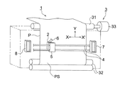
図1は、本発明に係るインクジェット記録装置の概略構成を示す図である。インクジェット記録装置1において、記録媒体Pは、搬送機構3の搬送ローラ対32に挟持され、更に、搬送モータ33によって回転駆動される搬送ローラ31により図示Y方向に搬送されるようになっている。
FIG. 1 is a diagram showing a schematic configuration of an ink jet recording apparatus according to the present invention. In the
搬送ローラ31と搬送ローラ対32の間には、記録媒体Pの記録面PSと対向するようにせん断モード方式の記録ヘッド2が設けられている。この記録ヘッド2は、記録媒体Pの幅方向に亘って掛け渡されたガイドレール4に沿って、不図示の駆動手段によって、上記記録媒体Pの搬送方向(副走査方向)と略直交する図示X−X’方向(主走査方向)に沿って往復移動可能に設けられたキャリッジ5に、ノズル面側が記録媒体Pの記録面PSと対向するように配置されて搭載されており、圧力室の隔壁に形成された電極(不図示)がフレキシブルケーブル6を介して、後述する吐出パルスや予備パルスを生成するための回路が設けられる駆動信号生成手段100(図3参照)に電気的に接続されている。
Between the
かかる記録ヘッド2は、キャリッジ5の移動に伴って記録媒体Pの記録面PSを図示X−X’方向に移動し、この移動過程でインク滴を吐出することによって所望のインクジェット画像を記録するようになっている。
The
なお、図中、7はインク受け器であり、記録ヘッド2が画像記録領域外、即ち、非記録時のホームポジション等の待機位置に設けられている。記録ヘッド2がこの待機位置にある時、ノズル開口で増粘したインクをインクリフレッシュのためにこのインク受け器7に向けてインク滴を少量はき捨てるようにする。記録ヘッド2がこの待機位置において長期間作動停止している時は、図示しないが、記録ヘッド2のノズル面にキャップを被せることにより保護するようになっている。また、8は記録媒体Pを挟んで上記インク受け器7の反対位置に設けられたインク受け器であり、往復両方向で記録するとき、往動から復動に切り替えるときに、上記同様にはき捨てられたインク滴を受け入れる。
In the figure,
このように、本実施形態におけるインク滴の吐出とは、画像記録のための吐出とインクリフレッシュのための画像記録領域外でのはき捨て等が挙げられる。本実施形態においては、インク滴の非吐出時、即ち、このようなインク滴の吐出を行わないときにノズル内のインクメニスカスをノズルからインク滴を吐出させない程度に微振動させる。 As described above, the ejection of ink droplets in this embodiment includes ejection for image recording and discarding outside the image recording area for ink refreshing. In the present embodiment, when ink droplets are not ejected, that is, when such ink droplets are not ejected, the ink meniscus in the nozzle is vibrated to such an extent that the ink droplet is not ejected from the nozzle.
ここで画像記録領域内とは、画像データが記録ヘッドに供給され、画像データに基づいて記録ヘッドのノズルからインク滴を吐出して記録が行われる領域であり、例えば記録媒体としてA4の大きさの紙の全面に記録する場合等は、A4の大きさの紙全面が画像記録領域となる。 Here, the image recording area is an area in which image data is supplied to the recording head and ink droplets are ejected from the nozzles of the recording head based on the image data. When recording on the entire surface of the paper, the entire surface of A4 size paper is the image recording area.
また、画像記録領域外とは、画像記録領域以外の領域であり、基本的には画像データが記録ヘッドには供給されず、すべてのノズルから画像データに基づくインク滴の吐出は行われない。また、非吐出画素とは画像記録領域内において、インク滴の吐出を行わない画素を指す。 Further, the area outside the image recording area is an area other than the image recording area. Basically, image data is not supplied to the recording head, and ink droplets are not ejected from all nozzles based on the image data. The non-ejection pixel refers to a pixel that does not eject ink droplets in the image recording area.
インクジェット用の液体インクは、色材やポリマー等を含むため吐出をごく短時間、例えば秒のオーダー停止しただけで、ノズル開口から極微量の水分や溶剤が蒸発し被膜を形成するため粘度が急上昇する。このことにより、ごく短時間の吐出中断時にもノズル詰まりが起こり易くなる。 Inkjet liquid ink contains coloring materials, polymers, etc., so that the viscosity rapidly increases because a very small amount of water or solvent evaporates from the nozzle opening to form a film just after the discharge is stopped for a very short time, for example, seconds. To do. As a result, nozzle clogging easily occurs even when discharge is interrupted for a very short time.
そこで、本実施形態では、インク滴を吐出しない時に、ノズル内のインクメニスカスをノズルからインク滴を吐出させない程度に微振動させることにより、ノズル内のインクを効率良く攪拌させ、低温・低湿環境下でもデキャップ特性の改善効果が高く、安定吐出を可能としている。 Therefore, in this embodiment, when ink droplets are not ejected, the ink meniscus in the nozzle is vibrated slightly to the extent that ink droplets are not ejected from the nozzle, so that the ink in the nozzle is efficiently stirred, and the environment is maintained in a low-temperature, low-humidity environment. However, the effect of improving the decap characteristics is high, enabling stable ejection.
ここで、デキャップ特性とは、ノズル面開放状態の場合にインクメニスカス乾燥によってインクが増粘する、いわゆるデキャップ現象による初発速度の低下量を示す。 Here, the decap characteristic indicates the amount of decrease in the initial speed due to the so-called decap phenomenon, in which the ink is thickened by ink meniscus drying when the nozzle surface is open.
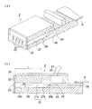
図2、図3は、せん断モード方式の記録ヘッド2の一例を示す図であり、図2(a)は概観斜視図、(b)は断面図、図3はインク吐出時の作動を示す図である。同図において、21はインクチューブ、22はノズル形成部材、23はノズル、24はカバープレート、25はインク供給口、26は基板、27は隔壁、Lは圧力室の長さ、Dは圧力室の深さ、Wは圧力室の幅である。そして、圧力室28が隔壁27、カバープレート24及び基板26によって形成されている。
2 and 3 are diagrams showing an example of a shear mode
記録ヘッド2は、ここでは図3に示すように、カバープレート24と基板26の間に、圧力発生手段であるPZT等の圧電材料からなる複数の隔壁27A、27B、27C、27Dで隔てられた圧力室28が多数並設されたせん断モード方式の記録ヘッドを示している。図3では多数の圧力室28の一部である3本(28A、28B、28C)が示されている。圧力室28の一端(以下、これをノズル端という場合がある)はノズル形成部材22に形成されたノズル23につながり、他端(以下、これをマニホールド端という場合がある)はインク供給口25を経て、インクチューブ21によって図示されていないインクタンクに接続されている。そして、各圧力室28内の隔壁27表面には両隔壁27の上方から基板26の底面に亘って繋がる電極29A、29B、29Cが密着形成され、各電極29A、29B、29Cは、異方導電性フィルム78とフレキシブルケーブル6を介して、駆動信号生成手段100に接続している。
Here, as shown in FIG. 3, the
また、圧力室28は、圧力室28の出口側(図2における左側)の深溝部28aと、該深溝部28aから圧力室28の入口側(図2における右側)に行くに従って徐々に浅くなる浅溝部28bとを有している。
Further, the
本実施形態において示したように、せん断モードで変形する圧電材料により構成される場合には、後述する矩形波をより効果的に利用することができ、駆動電圧を低下させ、より効率的な駆動が可能となる。 As shown in the present embodiment, when the piezoelectric material is deformed in the shear mode, a rectangular wave described later can be used more effectively, lowering the driving voltage and more efficient driving. Is possible.
駆動信号生成手段100は、複数の駆動パルスを含む一連の駆動信号を各画素周期毎に発生する駆動信号発生回路と、各圧力室毎に前記駆動信号発生回路から供給された駆動信号の中から各画素の画像データに応じて駆動パルスを選択して各圧力室に供給する駆動パルス選択回路とからなり、各画素の画像データに応じて圧力発生手段としての隔壁27を駆動するための駆動パルスを供給する。この駆動パルスには、予備パルスと吐出パルスとを含んでいる。
The drive
画像データを受信すると、制御部(図示せず)が搬送ローラのモータ及びキャリッジの駆動手段をそれぞれ制御すると共に、駆動信号発生回路に少なくとも予備パルスと吐出パルスを含む駆動パルスを有する駆動信号を発生させる。さらに、制御部は、上記画像データに基づいて、駆動パルス選択回路に選択すべき駆動パルスの情報を出力する。そして、駆動パルス選択回路は、上記情報に基づいて、駆動パルスを選択して隔壁27に供給する。これにより、記録ヘッド2のノズル23から、一画素周期内にインク滴が吐出可能になっている。
When the image data is received, a control unit (not shown) controls the motor of the conveyance roller and the driving unit of the carriage, and generates a drive signal having a drive pulse including at least a preliminary pulse and an ejection pulse in the drive signal generation circuit. Let Further, the control unit outputs information on the drive pulse to be selected to the drive pulse selection circuit based on the image data. Then, the drive pulse selection circuit selects a drive pulse based on the information and supplies it to the
各隔壁27は、ここでは図3の矢印で示すように分極方向が異なる2枚の圧電材料27a、27bによって構成されているが、圧電材料は例えば符号27aの部分のみであってもよく、隔壁27の少なくとも一部にあればよい。
Here, each
本発明において、インク滴を吐出させるために圧力発生手段に印加する駆動信号が、圧力室の容積を膨張させた後に収縮させる第1のパルスを有する吐出パルスと、該吐出パルスの直前に印加され圧力室の容積を収縮させた後に膨張させる予備パルスとを含み、前記予備パルスはパルス幅が2AL(ALは圧力室における圧力波の音響的共振周期の1/2)以上の矩形波であることを特徴とする。 In the present invention, the drive signal applied to the pressure generating means for ejecting the ink droplets is applied immediately before the ejection pulse having the first pulse for contracting after expanding the volume of the pressure chamber. A preliminary pulse that expands after contracting the volume of the pressure chamber, and the preliminary pulse is a rectangular wave having a pulse width of 2AL (AL is 1/2 of the acoustic resonance period of the pressure wave in the pressure chamber) or more. It is characterized by.
なお、AL(Acoustic Length)とは、圧力室における圧力波の音響的共振周期の1/2である。またパルス幅とは、電圧の立ち上がり始めから10%と立ち下がり始めから10%との間の時間と定義する。このALは、圧力発生手段である隔壁27に矩形波の電圧パルスを印加して吐出するインク滴の速度を測定し、矩形波の電圧値を一定にして矩形波のパルス幅を変化させたときに、インク滴の飛翔速度が最大になるパルス幅として求められる。さらにここで矩形波は、駆動電圧の10%と90%との間の立ち上がり時間、立ち下がり時間のいずれもがALの1/2以内、好ましくは1/4以内であるような波形である。
Note that AL (Acoustic Length) is ½ of the acoustic resonance period of the pressure wave in the pressure chamber. The pulse width is defined as the time between 10% from the start of voltage rise and 10% from the start of voltage fall. This AL is obtained when a rectangular wave voltage pulse is applied to the
また、直前とは、予備パルス印加後の吐出パルスによるインク滴の吐出において小液滴化に効果が見られる範囲の時間を指し、好ましくは、本実施形態において用いる図10(b)〜(f)に示す駆動信号のように予備パルスに引き続いて吐出パルスを印加することで、予備パルスによる引き打ち効果を高めることが可能な構成である。 Further, the term “immediately before” refers to a time within a range in which the effect of reducing ink droplets in the ejection of ink droplets by ejection pulses after application of a preliminary pulse is applied. Preferably, FIGS. 10B to 10F used in the present embodiment. In this configuration, the ejection pulse can be enhanced by applying the ejection pulse subsequent to the preliminary pulse as shown in FIG.
図10(d)は、本発明における駆動信号の一例を示している。この例では、駆動信号は予備パルスと吐出パルス各1種の駆動パルスで構成されたものを例に説明する。 FIG. 10 (d) shows an example of the drive signal in the present invention. In this example, a description will be given by taking an example in which the drive signal is composed of one kind of drive pulse for each of the preliminary pulse and the ejection pulse.
各隔壁27表面に密着形成された電極29A、29B、29Cに駆動信号生成手段100の制御により図10(d)に示すような、駆動電圧(波高値)Von、パルス幅1ALで正電圧の第1のパルスと、第1のパルスから1AL時間後に印加され駆動電圧(波高値)Voff、パルス幅1ALで負電圧の第2のパルスとからなる吐出パルスと、吐出パルスの直前に印加され駆動電圧(波高値)Voff、パルス幅4ALで負電圧の予備パルスが印加されると、以下に例示する動作によってインク滴をノズル23から吐出する。ここで、第1のパルス、第2のパルス、予備パルスはいずれも矩形波である。なお、図3ではノズルは省略してある。
The
まず、電極29A、29B、29Cのいずれにも駆動パルスが印加されない時は、隔壁27A、27B、27Cのいずれも変形しないが、図3(a)に示す状態において、電極29A及び29Cを接地すると共に電極29Bに予備パルスを印加すると、隔壁27B、27Cを構成する圧電材料の分極方向に直角な方向の電界が生じ、各隔壁27B、27C共に、それぞれ隔壁27a、27bの接合面にズリ変形を生じ、図3(c)に示すように隔壁27B、27Cは互いに内側に向けて変形し、圧力室28Bの容積を収縮して圧力室28B内に正の圧力が生じる。これにより圧力室28Bを満たしているインクの一部によるノズル内のインクメニスカスがノズルから押し出される方向に変化する。この正の圧力はインク滴をノズルから吐出する程に大きくはなく、インク滴がノズルから吐出することはない。
First, when no drive pulse is applied to any of the
その後、電位を0に戻して、隔壁27B、27Cを図3(c)に示す収縮位置から図3(a)に示す中立位置に戻し、次いで、図3(b)に示すように、隔壁27B、27Cを互いに逆方向に変形するように第1のパルスを印加して、圧力室28Bの容積を急激に膨張すると、圧力室28B内に大きな負の圧力が生じる。これによりノズルから押し出されていたインクメニスカスはノズル内に大きく引き込まれる。
Thereafter, the potential is returned to 0, and the
その後、電位を0に戻すと、隔壁27B、27Cは図3(b)に示す膨張位置から図3(a)に示す中立位置に戻り、圧力室28B内に正の圧力が生じる。これにより、それまでノズル内に大きく引き込まれていたインクメニスカスは、その一部がノズルから押し出され、その後インクメニスカスから分断されて微小なインク滴として吐出する。
Thereafter, when the potential is returned to 0, the
さらに1AL時間後、続いて第2のパルスが印加されると、図3(c)に示すように隔壁27B、27Cは互いに内側に向けて変形し、圧力室28Bの容積を収縮して圧力室28B内に正の圧力が生じ、圧力室内の圧力波残響をキャンセルする。
Further, after 1 AL time, when the second pulse is applied subsequently, as shown in FIG. 3C, the
その後、電位を0に戻すと、隔壁27B、27Cは図3(c)に示す収縮位置から図3(a)に示す中立位置に戻り、圧力室28B内に負の圧力が生じ、圧力室内の圧力波残響をキャンセルする。他の各圧力室も予備パルスと吐出パルスの印加によって上記と同様に動作する。
Thereafter, when the potential is returned to 0, the
以上のように、予備パルスはそのパルス自体ではインク滴を吐出させるまでに至らないレベルの非吐出パルスであり、本実施形態においては、第1のパルスの駆動電圧Von、予備パルスの駆動電圧Voffは、|Von|>|Voff|に設定されている。 As described above, the preliminary pulse is a non-ejection pulse at a level that does not cause the ink droplet to be ejected by the pulse itself. In the present embodiment, the driving voltage Von of the first pulse and the driving voltage Voff of the preliminary pulse are used. Is set to | Von |> | Voff |.
予備パルスは1滴のインク滴を吐出する駆動信号の先頭にあって、インク滴を吐出させるまでに至らない状態に圧力室を収縮する。第1のパルスは、予備パルスに引き続き印加され、インクメニスカスをノズルの内部に大きく後退させた後押し出して微小インク滴を吐出させる。第2のパルスは、第1のパルスのあとで、第1のパルスに対し逆位相の圧力波を発生することにより、圧力室内の圧力波残響をキャンセルする。これにより、駆動周期を短くして駆動周波数を上げても安定に微小のインク滴を吐出できる。 The preliminary pulse is at the head of the drive signal for ejecting one ink droplet, and contracts the pressure chamber so that the ink droplet is not ejected. The first pulse is applied subsequently to the preliminary pulse, and after the ink meniscus is largely retracted into the nozzle, it is pushed out to eject a minute ink droplet. The second pulse cancels the pressure wave reverberation in the pressure chamber by generating a pressure wave having a phase opposite to that of the first pulse after the first pulse. As a result, even if the driving cycle is shortened and the driving frequency is increased, minute ink droplets can be stably ejected.
そして、予備パルスはパルス幅が2AL(ALは圧力室における圧力波の音響的共振周期の1/2)以上であることにより、せん断モード方式の記録ヘッドに駆動回路の簡素化を図ることが可能な矩形波の予備パルスを用いて、圧力室内の圧力波振動の影響を抑えながらノズル内のメニスカス位置を大きく引き込むことが可能になり、微小液滴を吐出することができる。 The preliminary pulse has a pulse width of 2AL (AL is 1/2 of the acoustic resonance period of the pressure wave in the pressure chamber) or more, so that the drive circuit can be simplified in the shear mode type recording head. By using a preparatory pulse of a rectangular wave, it is possible to largely draw the meniscus position in the nozzle while suppressing the influence of pressure wave vibration in the pressure chamber, and it is possible to discharge micro droplets.
その理由は、予備パルスの印加開始時の収縮により生じた正の圧力波は圧力室を伝播する際に時間の経過とともに減衰していくので、ALの2倍以上経過して減衰を待ってから予備パルスの印加解除及び第1のパルスの印加開始による膨張を加えることにより、圧力室内の圧力波振動の影響を抑えながらノズル内のメニスカス位置を大きく引き込むことが可能になり、微小液滴を吐出することができるものと考えられる。 The reason is that the positive pressure wave generated by the contraction at the start of the application of the preliminary pulse attenuates with the passage of time when propagating through the pressure chamber. By applying the expansion by releasing the application of the preliminary pulse and starting the application of the first pulse, it becomes possible to draw the meniscus position in the nozzle greatly while suppressing the influence of the pressure wave vibration in the pressure chamber, and discharge a minute droplet. It is thought that it can be done.
また、矩形波は台形波などのスロープ波に比べて、駆動パルスの長さが短くて済むので矩形波の予備パルスを組み込んでも印刷速度が大きく低下することがない。更に、矩形波は、簡単なデジタル回路を用いることで容易に生成可能であるため、台形波に比べて、回路構成も簡素化できる利点がある。 Further, since the rectangular wave has a shorter drive pulse length than the slope wave such as a trapezoidal wave, the printing speed is not greatly reduced even if the rectangular wave preliminary pulse is incorporated. Furthermore, since the rectangular wave can be easily generated by using a simple digital circuit, there is an advantage that the circuit configuration can be simplified as compared with the trapezoidal wave.
さらに、吐出パルスに矩形波を用いることにより、すべての駆動パルスを矩形波のみで構成でき、駆動回路の更なる簡素化を図ることが可能になる。また、駆動電圧を低減する効果も得られる。 Furthermore, by using a rectangular wave for the ejection pulse, all the driving pulses can be configured only by the rectangular wave, and the driving circuit can be further simplified. In addition, an effect of reducing the driving voltage can be obtained.
図5に示す例では、第1のパルスの駆動電圧Vonと第2のパルスの駆動電圧Voffは、|Von|>|Voff|とすることが好ましい。|Von|>|Voff|の関係とすると、特に吐出するインクの粘度が高い場合において吐出後のノズル内のインクメニスカスの定常状態への復帰を促進する効果があり、高速安定吐出が可能となり、好ましい態様である。また、引き打ちによる小液滴化効果を大きくすると共に、第2のパルスによるキャンセル効果を高めることができる。なお、この駆動電圧Vonと駆動電圧Voffの基準電圧は0とは限らない。この駆動電圧Vonと駆動電圧Voffは、それぞれ基準電圧からの差分の電圧である。更に、|Von|/|Voff|=2とすることがより好ましい。第1のパルスによって生じた圧力波が、第1のパルスから1AL時間後に印加する第2のパルスによって生ずる圧力波に適正にキャンセルされるためには、|Von|/|Voff|を圧力波振動の減衰率に合わせる必要がある。インクジェットヘッドで吐出する標準的な粘度範囲のインクの場合、この減衰率がおよそ0.5であるため、駆動電圧比である|Von|/|Voff|は、2付近が望ましい。 In the example shown in FIG. 5, the drive voltage Von of the first pulse and the drive voltage Voff of the second pulse are preferably set to | Von |> | Voff |. The relationship of | Von |> | Voff | has an effect of promoting the return of the ink meniscus in the nozzle after ejection to a steady state, particularly when the viscosity of the ejected ink is high, and enables high-speed stable ejection. This is a preferred embodiment. In addition, it is possible to increase the effect of reducing droplets by the strike and to enhance the cancellation effect by the second pulse. Note that the reference voltage of the drive voltage Von and the drive voltage Voff is not necessarily zero. The drive voltage Von and the drive voltage Voff are respectively differential voltages from the reference voltage. Furthermore, it is more preferable that | Von | / | Voff | = 2. In order for the pressure wave generated by the first pulse to be appropriately canceled by the pressure wave generated by the second pulse applied 1 AL time after the first pulse, | Von | / | Voff | It is necessary to match the attenuation rate. In the case of ink having a standard viscosity range ejected by an ink jet head, the attenuation rate is about 0.5, and therefore, the drive voltage ratio | Von | / | Voff |
また、予備パルスは、前記吐出パルスの第2のパルスの駆動電圧Voffと同電圧に設定している。これは、吐出パルス及び予備パルスを発生するための駆動信号生成手段100における電源電圧数を少なくして回路コストを下げることができるために好ましい態様である。 The preliminary pulse is set to the same voltage as the drive voltage Voff of the second pulse of the ejection pulse. This is a preferable mode because the circuit cost can be reduced by reducing the number of power supply voltages in the drive signal generating means 100 for generating the ejection pulse and the preliminary pulse.
このように少なくとも一部が圧電材料で構成された隔壁27によって隔てられた複数の圧力室28を有する記録ヘッド2を駆動する場合、一つの圧力室の隔壁が吐出の動作をすると、隣の圧力室が影響を受けるため、通常、複数の圧力室28のうち、互いに1本以上の圧力室28を挟んで離れている圧力室28をまとめて1つの組となすようにして、2つ以上の組に分割し、各組毎にインク吐出動作を時分割で順次行うように駆動制御される。
When the
例えば、全圧力室28を駆動してベタ画像を出力する場合には、圧力室28を2つおきに選んで3相に分けて吐出する、いわゆる3サイクル吐出法が行われる。また、別の圧力室構成として、圧力室と該圧力室の少なくとも両隣にインクを含まない、即ちインクの吐出を行わない空気室(ダミーチャネル)を交互に設けて、インク滴を吐出した圧力室の影響が、その隣の圧力室に伝わらないようにする方法がある。この場合、各圧力室は同じタイミングでインク滴の吐出を行うことができる。本発明は上記いずれの方法にも適用可能であるが、特に後者の場合、インク滴をより安定して吐出可能となるために好ましい。
For example, when all the
かかる3サイクル吐出動作について図4を用いて更に説明する。図4に示す例では、記録ヘッドは圧力室がA1、B1、C1、A2、B2、C2、A3、B3、C3の9つの圧力室28で構成されているとして説明する。また、このときのA、B、Cの各組の圧力室28に印加される駆動パルスのタイミングチャートを図5に示す。
Such a 3-cycle discharge operation will be further described with reference to FIG. In the example shown in FIG. 4, the recording head is described on the assumption that the pressure chambers are composed of nine pressure chambers A1, B1, C1, A2, B2, C2, A3, B3, and C3. In addition, FIG. 5 shows a timing chart of drive pulses applied to the
インク吐出時には、まずA組(A1、A2、A3)の各圧力室の電極に電圧を印加し、その両隣のB組、C組の圧力室の電極を接地する。A組の圧力室に予備パルスと吐出パルスを印加すると、吐出したいA組の圧力室から微小インク滴が吐出される。 At the time of ink ejection, first, a voltage is applied to the electrodes of the pressure chambers of the A group (A1, A2, A3), and the electrodes of the B group and C group of the pressure chambers adjacent to both are grounded. When a preliminary pulse and an ejection pulse are applied to the A set of pressure chambers, minute ink droplets are ejected from the A set of pressure chambers to be ejected.
続いてB組(B1、B2、B3)の各圧力室28、更に続いてC組(C1、C2、C3)の各圧力室28へと上記同様に動作する。
Subsequently, the operation is performed in the same manner as described above for each
かかるせん断モード方式の記録ヘッドでは、隔壁の変形は壁の両側に設けられる電極に掛かる電圧差で起こるので、インク吐出を行う圧力室の電極に負電圧を掛ける代わりに、図6に示すように、インク吐出を行う圧力室の電極を接地して、その両隣の圧力室の電極に正電圧を掛けるようにしても同様に動作させることができる。この後者の方法によれば、図5の駆動信号を印加した場合と全く同一の効果を奏することができる上に、正電圧のみによって回路構成が可能であるため、回路設計上有利である。 In such a shear mode type recording head, the deformation of the partition wall is caused by a voltage difference applied to the electrodes provided on both sides of the wall. Therefore, instead of applying a negative voltage to the electrode of the pressure chamber for ink ejection, as shown in FIG. The same operation can be performed by grounding the electrode of the pressure chamber for discharging ink and applying a positive voltage to the electrodes of the pressure chambers on both sides thereof. According to this latter method, the same effect as that when the drive signal of FIG. 5 is applied can be obtained, and a circuit configuration can be made only with a positive voltage, which is advantageous in terms of circuit design.
次に、図7を用いて、かかるせん断モード方式の記録ヘッド2において、画像記録領域内で、インク滴を吐出しない圧力室のノズル内のインクメニスカスに微振動を与える動作について説明する。ここでも上記同様に3サイクル吐出動作を行うものについて説明する。また、ここでは、A組、B組、C組の圧力室がいずれも吐出を行わず、A組→B組→C組の順にメニスカスに微振動を与える場合について説明する。
Next, with reference to FIGS. 7A and 7B, an operation of giving a slight vibration to the ink meniscus in the nozzle of the pressure chamber that does not eject ink droplets in the image recording area in the shear
本実施形態においてノズルからインク滴を吐出させない程度に微振動させる微振動パルスとして、予備パルスと第2のパルスの何れか一方のみ、あるいは、両方を印加する。ここでは、図6に示す予備パルスと第2のパルスを利用する。また、微振動パルスは矩形波からなることが好ましい。 In the present embodiment, only one or both of the preliminary pulse and the second pulse are applied as the fine vibration pulse for causing the ink droplets to vibrate so as not to be ejected from the nozzle. Here, the preliminary pulse and the second pulse shown in FIG. 6 are used. Moreover, it is preferable that the fine vibration pulse is a rectangular wave.
微振動パルスに矩形波を用いることで、台形波を使用する方法に比べてメニスカスを微振動させる効率が良く、低い駆動電圧で振動させることができる上に、簡単なデジタル回路で駆動回路を設計できる効果がある。 By using a square wave for the micro-vibration pulse, the efficiency of micro-vibration of the meniscus can be improved compared to the method using a trapezoidal wave, and the drive circuit can be designed with a simple digital circuit. There is an effect that can be done.
例えば、図7に示す例では、画像記録領域内において、始めにA組の圧力室の電極を接地し、B組及びC組の圧力室の電極に4AL幅の正電圧の矩形波からなる予備パルスと1AL幅の正電圧の矩形波からなる第2のパルスのみを印加している。これによりA組の圧力室のノズル内のメニスカスは、ノズルからインク滴を吐出させない程度に押し出させるように微振動が与えられ、B組及びC組の各圧力室は片側の隔壁のみが変位して、A組の圧力室の半分の強度の微振動が与えられる。 For example, in the example shown in FIG. 7, in the image recording area, first, the electrodes of the A set of pressure chambers are grounded, and the electrodes of the B set and C set of pressure chambers are preliminarily made of a rectangular wave with a positive voltage of 4 AL width. Only a second pulse composed of a pulse and a rectangular wave with a positive voltage of 1 AL width is applied. As a result, the meniscus in the nozzles of the A set of pressure chambers is finely oscillated so as not to eject ink droplets from the nozzles, and each of the pressure chambers of the B set and C set is displaced by only one partition. Thus, a slight vibration with half the strength of the A set of pressure chambers is applied.
A組の圧力室の微振動が終了し、続いてB組の圧力室を微振動させる場合も同様に、B組の圧力室の電極を接地してからA組及びC組の圧力室の電極にそれぞれ4AL幅の正電圧の矩形波からなる予備パルスと1AL幅の正電圧の矩形波からなる第2のパルスのみを印加し、メニスカスを微振動させる。C組の圧力室の予備パルスと第2のパルスの印加及び微振動も同様に行われる。 Similarly, when the fine vibration of the A set of pressure chambers is finished and then the B set of pressure chambers are finely vibrated, the electrodes of the B set pressure chambers are grounded, and then the electrodes of the A set and C set pressure chambers are ground. Only a preliminary pulse consisting of a square wave with a positive voltage of 4 AL width and a second pulse consisting of a rectangular wave with a positive voltage of 1 AL width are applied to each to slightly vibrate the meniscus. The application of the preliminary pulse and the second pulse in the C pressure chambers and the fine vibration are performed in the same manner.
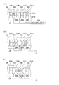
続いて、各画素内における駆動パルスの選択方法について、図8及び図9を用いて説明する。図8及び図9のON波形およびOFF波形は、駆動信号発生回路が生成する2種類の駆動信号を示す。 Next, a method for selecting a drive pulse in each pixel will be described with reference to FIGS. The ON waveform and the OFF waveform in FIGS. 8 and 9 indicate two types of drive signals generated by the drive signal generation circuit.
この駆動信号におけるOFF波形は、予備パルスと吐出パルスの第2のパルスに対応し、ON波形は吐出パルスの第1のパルスに対応している。また、図示していないが、ON波形としてはGND(アース電位)も選択することができるようになっている。ここで、予備パルスの駆動電圧が吐出パルスを構成する第2のパルスの駆動電圧Voffと同電圧に設定されているため、ON波形及びOFF波形は、それぞれ単一の電源電圧、Von及びVoffをデジタル的にスイッチングするのみで波形を生成することができる。 The OFF waveform in this drive signal corresponds to the second pulse of the preliminary pulse and the ejection pulse, and the ON waveform corresponds to the first pulse of the ejection pulse. Although not shown, GND (ground potential) can be selected as the ON waveform. Here, since the drive voltage of the preliminary pulse is set to the same voltage as the drive voltage Voff of the second pulse that constitutes the ejection pulse, the ON waveform and the OFF waveform have a single power supply voltage, Von and Voff, respectively. Waveforms can be generated only by digital switching.
ON波形およびOFF波形は、各圧力室の駆動パルス選択回路にそれぞれ供給されており、各圧力室の画像データに応じたパルス選択ゲート信号の制御により、各圧力室の電極へ選択的に供給される。 The ON waveform and the OFF waveform are respectively supplied to the driving pulse selection circuit of each pressure chamber, and are selectively supplied to the electrodes of each pressure chamber by controlling the pulse selection gate signal according to the image data of each pressure chamber. The
駆動パルス選択回路は、パルス選択ゲート信号がHighのときにはON波形あるいはGND(アース電位)を電極に供給し、パルス選択ゲート信号がLowのときにはOFF波形を電極に供給する。具体的には、Highの場合、吐出画素(印字画素)にはON波形を、非吐出画素(非印字画素)にはGND(アース電位)を供給する。 The drive pulse selection circuit supplies an ON waveform or GND (ground potential) to the electrode when the pulse selection gate signal is High, and supplies an OFF waveform to the electrode when the pulse selection gate signal is Low. Specifically, in the case of High, an ON waveform is supplied to ejection pixels (printing pixels), and GND (ground potential) is supplied to non-ejection pixels (non-printing pixels).
まず、A組、B組、C組の圧力室のいずれもインク吐出を行う場合について図8を用いて説明する。 First, the case where ink is ejected in any of the pressure chambers of the A group, the B group, and the C group will be described with reference to FIG.
3サイクル駆動であるので、まず吐出タイミングとなるA組の圧力室に画像データが供給されパルス選択ゲート信号がHighになり、B組、C組の圧力室は吐出タイミングではないので画像データが供給されずパルス選択ゲート信号がLowになる。次に吐出タイミングとなるB組の圧力室に画像データが供給されパルス選択ゲート信号がHighになり、A組、C組の圧力室は吐出タイミングではないので画像データが供給されずパルス選択ゲート信号がLowになる。次に吐出タイミングとなるC組の圧力室に画像データが供給されパルス選択ゲート信号がHighになり、A組、B組の圧力室は吐出タイミングではないので画像データが供給されずパルス選択ゲート信号がLowになる。以降は同様の動作が繰り返される。 Since it is a 3-cycle drive, first, image data is supplied to the A set of pressure chambers at the discharge timing, the pulse selection gate signal becomes High, and the B and C pressure chambers are not at the discharge timing, so the image data is supplied. The pulse selection gate signal goes low. Next, image data is supplied to the B pressure chambers at the discharge timing, and the pulse selection gate signal becomes High. Since the A and C pressure chambers are not at the discharge timing, no image data is supplied and the pulse selection gate signal is supplied. Becomes Low. Next, the image data is supplied to the C pressure chambers at the discharge timing, and the pulse selection gate signal becomes High. Since the A and B pressure chambers are not at the discharge timing, the image data is not supplied and the pulse selection gate signal is supplied. Becomes Low. Thereafter, the same operation is repeated.
図8は、A組、B組、C組の各圧力室駆動の1周期分を表記しているが、以降は、A組圧力室駆動のタイミングを例として説明する。 FIG. 8 shows one cycle of each pressure chamber drive of the A group, the B group, and the C group. Hereinafter, the timing of the A group pressure chamber drive will be described as an example.
予備パルスの印加前の期間および吐出パルス印加後の期間には、それぞれパルス分割信号が印加される。画素に吐出の画像データが与えられると、それに応じてパルス分割信号に同期したパルス選択ゲート信号がHighとなる。A組圧力室に対応するパルス選択ゲート信号がHighである期間(図8の(1))は、A組圧力室の電極には駆動信号のON波形が印加され、このとき、B組およびC組圧力室に対応するパルス選択ゲート信号はLowであるから、B組およびC組の圧力室の電極にはOFF波形が印加されて、A組圧力室の両側の隔壁が変位し、A組の圧力室のノズルからインク滴が吐出する。B組、C組圧力室駆動のタイミングも同様に動作する。 A pulse division signal is applied in the period before the application of the preliminary pulse and the period after the application of the ejection pulse. When ejection image data is given to the pixel, the pulse selection gate signal synchronized with the pulse division signal becomes High accordingly. During the period when the pulse selection gate signal corresponding to the A set pressure chamber is High ((1) in FIG. 8), the ON waveform of the drive signal is applied to the electrode of the A set pressure chamber. Since the pulse selection gate signal corresponding to the set pressure chamber is Low, an OFF waveform is applied to the electrodes of the B set and C set pressure chambers, and the partition walls on both sides of the A set pressure chamber are displaced, and Ink droplets are ejected from the nozzles of the pressure chamber. The timing for driving the B-group and C-group pressure chambers also operates in the same manner.
次に、A組、B組、C組の圧力室がいずれもインク吐出を行わず、A組→B組→C組の順にメニスカスに微振動を与える場合について図9を用いて説明する。 Next, the case where none of the pressure chambers of the A group, the B group, and the C group performs ink ejection and gives a slight vibration to the meniscus in the order of A group → B group → C group will be described with reference to FIG.
予備パルスの印加前の期間および吐出パルス印加後の期間には、それぞれパルス分割信号が印加される。画素に非吐出の画像データが与えられると、それに応じてパルス分割信号に同期したパルス選択ゲート信号がHighとなる。A組圧力室に対応するパルス選択ゲート信号がHighである期間(図9の(1))は、A組圧力室の電極には駆動信号としてGNDが供給され、このとき、B組およびC組圧力室に対応するパルス選択ゲート信号はLowであるから、B組およびC組の圧力室の電極にはOFF波形が印加されて、A組圧力室の両側の隔壁が変位し、A組の圧力室のノズル内のインクメニスカスに微振動が与えられる。B組、C組圧力室駆動のタイミングも同様に動作する。 A pulse division signal is applied in the period before the application of the preliminary pulse and the period after the application of the ejection pulse. When non-ejection image data is given to the pixel, the pulse selection gate signal synchronized with the pulse division signal becomes High accordingly. During the period when the pulse selection gate signal corresponding to the A set pressure chamber is High ((1) in FIG. 9), GND is supplied to the electrodes of the A set pressure chamber as a drive signal. Since the pulse selection gate signal corresponding to the pressure chamber is Low, the OFF waveform is applied to the electrodes of the pressure chambers of the B group and the C group, the partition walls on both sides of the A group pressure chamber are displaced, and the pressure of the A group A slight vibration is applied to the ink meniscus in the nozzle of the chamber. The timing for driving the B-group and C-group pressure chambers also operates in the same manner.
このように、非吐出画素にも常に、OFF波形を印加していることで、ノズル開口付近のインクの増粘を効果的に抑制することができる。 As described above, by always applying the OFF waveform to the non-ejection pixels, it is possible to effectively suppress the thickening of the ink near the nozzle opening.
また、予備パルスと第2のパルスを微振動パルスに利用し、微振動パルスの駆動電圧を電圧の低いVoff電圧に設定することで、微振動が強く掛かりすぎることがなく、インク滴をノズルから吐出させない程度の微振動を効率良く掛けることができる。 In addition, by using the preliminary pulse and the second pulse as the micro-vibration pulse and setting the drive voltage of the micro-vibration pulse to a low Voff voltage, the micro-vibration is not excessively applied and the ink droplets are discharged from the nozzle. It is possible to efficiently apply a slight vibration that does not cause ejection.
以上の実施の形態例の説明では、画像記録領域内の非吐出画素に対応してインク滴を吐出しない圧力室の隔壁の電極に予備パルスと第2のパルスからなる微振動パルスを駆動信号生成手段100から出力する場合について説明したが、第1の実施の形態例において、画像記録領域以外でも同様にして駆動信号生成手段100から微振動パルスを出力することが好ましい。
In the above description of the embodiment, a micro-vibration pulse consisting of a preliminary pulse and a second pulse is generated on the electrode of the partition wall of the pressure chamber that does not eject ink droplets corresponding to the non-ejection pixels in the image recording area. Although the case of outputting from the
例えば、記録紙の画像記録領域内で微振動パルスを出力すると共に、画像記録領域外でも微振動パルスを出力させる。 For example, the fine vibration pulse is outputted within the image recording area of the recording paper, and the fine vibration pulse is outputted even outside the image recording area.
このようにすることで、画像記録領域外での吐出ノズルの乾燥を有効に防止でき、画像記録領域の記録開始点や各ラインの開始点において良好なインク液滴の吐出を行うことが可能になる。 In this way, it is possible to effectively prevent the discharge nozzles from drying out of the image recording area, and it is possible to perform good ink droplet discharge at the recording start point of the image recording area and the start point of each line. Become.
なお画像記録領域外における記録ヘッドの基本的な駆動方法は、上記実施形態例の画像記録領域内の駆動と同様であるので説明は省略する。画像記録領域外においては、画像データがないので、例えば、図7のような微振動パルスを用いて、ヘッドが画像記録領域外の例えば待機ポジションにある時に全ノズルに微振動を掛けてノズル開口面のインク粘度を下げてやると、どのノズルも第1滴から安定したインク滴の吐出が可能となる。 The basic driving method of the recording head outside the image recording area is the same as the driving in the image recording area of the above-described embodiment, and the description thereof will be omitted. Since there is no image data outside the image recording area, for example, a slight vibration pulse as shown in FIG. 7 is used to apply a slight vibration to all nozzles when the head is at a standby position outside the image recording area. If the ink viscosity of the surface is lowered, any nozzle can stably discharge ink droplets from the first droplet.
また、キャリッジ往復走査の戻りにおいて、単に戻り動作だけであれば微振動パルスのみを駆動信号生成手段100から出力させる。単なる戻り動作でなく記録を実行する場合には上述した実施の形態例と同様な動作をさせるようにする。 Further, in the return of the carriage reciprocating scanning, only the fine vibration pulse is output from the drive signal generating means 100 if only the return operation is performed. When recording is performed instead of a simple return operation, an operation similar to that of the above-described embodiment is performed.
前記実施形態例における吐出パルス、予備パルスは、他の波形にすることも可能である。図10の(b)〜(c)、(e)〜(f)に例を示す。 The ejection pulse and the preparatory pulse in the above-described embodiment can have other waveforms. Examples are shown in (b) to (c) and (e) to (f) of FIG.
例えば、吐出パルスとしては、圧力室の容積を膨張させた後に収縮させる第1のパルスを有していればよく、図10の(e)に示すように、第1のパルスに引き続いて圧力室の容積を収縮させた後に膨張させる第2のパルスを印加して液滴を吐出させるようなパルスでも、図10の(f)に示すように、第1のパルスのみにより液滴を吐出させるような片極の吐出パルスでもよい。 For example, the discharge pulse may have a first pulse that is contracted after the volume of the pressure chamber is expanded. As shown in FIG. 10 (e), the pressure chamber follows the first pulse. Even in a pulse in which a second pulse that is expanded after contracting the volume of the liquid is applied to eject a droplet, the droplet is ejected only by the first pulse as shown in FIG. A simple unipolar discharge pulse may be used.
図10の(e)の場合の微振動パルスは、パルス幅が4ALの予備パルスとパルス幅が2ALの第2のパルスのみとなる。図10の(f)の場合の微振動パルスは、パルス幅が4ALの予備パルスのみとなる。 The micro-vibration pulse in the case of (e) in FIG. 10 is only a preliminary pulse having a pulse width of 4AL and a second pulse having a pulse width of 2AL. The fine vibration pulse in the case of (f) in FIG. 10 is only a preliminary pulse having a pulse width of 4AL.
また、予備パルスは、パルス幅が、2AL(ALは圧力室における圧力波の音響的共振周期の1/2)以上である矩形波であればよく、図10の(b)、(c)に示すように、パルス幅2ALや3ALにしてもよい。後述する実施例に示すように,3.5AL以上にすると小液滴効果を高めることが可能になり好ましい。 Further, the preliminary pulse may be a rectangular wave having a pulse width of 2AL (AL is 1/2 of the acoustic resonance period of the pressure wave in the pressure chamber) or more, as shown in FIGS. 10 (b) and 10 (c). As shown, the pulse width may be 2AL or 3AL. As shown in the examples described later, it is preferable to use 3.5 AL or more because the small droplet effect can be enhanced.
予備パルスのパルス幅の上限は、高周波駆動を行う観点から10AL以下が好ましい。また、後述する実施例に示すように,予備パルスのパルス幅が2AL以上の範囲において、パルス幅が大きいほど、吐出動作前のメニスカス振動を抑制できるため、液滴質量は小さくなる傾向にある。このように、予備パルスのパルス幅が大きい方が本発明の効果が大きくなるということになるが、パルス幅が6ALに近づくにつれてパルス幅の増加に対する液滴質量の減少の割合は小さくなっており、パルス幅の増加による駆動周波数の低下を考慮すると6AL以下がより好ましく、4.5AL以下が最も好ましい。 The upper limit of the pulse width of the preliminary pulse is preferably 10 AL or less from the viewpoint of performing high frequency driving. Further, as shown in the examples described later, in the range where the pulse width of the preliminary pulse is 2AL or more, the larger the pulse width, the more meniscus vibration before the discharge operation can be suppressed, and thus the droplet mass tends to be smaller. As described above, the effect of the present invention becomes larger when the pulse width of the preliminary pulse is larger. However, as the pulse width approaches 6AL, the ratio of the decrease in droplet mass to the increase in pulse width decreases. Considering a decrease in driving frequency due to an increase in pulse width, 6 AL or less is more preferable, and 4.5 AL or less is most preferable.
以下、本発明の実施例を挙げて説明するが、本発明はこれらの例に限定されるものではない。
<実施例1>
図2に示すせん断モード方式の記録ヘッド(ノズル数:256、ノズル径:23μm、AL:3.0μs)の各圧力室を3群に分け、図6に示す駆動信号を基本として、予備パルスのパルス幅(予備パルス幅)を図12及び図13に示すように変化させながら、以下の条件で3サイクル駆動を行い、吐出したインク滴の飛翔速度が6m/sとなる駆動電圧(Von)で吐出したインク滴の液滴質量を測定した。
Examples of the present invention will be described below, but the present invention is not limited to these examples.
<Example 1>
Each pressure chamber of the shear mode type recording head (nozzle number: 256, nozzle diameter: 23 μm, AL: 3.0 μs) shown in FIG. 2 is divided into three groups, and based on the drive signal shown in FIG. While changing the pulse width (preliminary pulse width) as shown in FIG. 12 and FIG. 13, three-cycle driving is performed under the following conditions, and the driving voltage (Von) at which the ejection speed of the ejected ink droplet is 6 m / s. The droplet mass of the ejected ink droplet was measured.
なお、吐出パルスは、図6に示すように、圧力室の容積を膨張させた後に収縮させて元の容積に戻す矩形波からなる第1のパルスと、第1のパルスから1AL時間後に印加され圧力室の容積を収縮させた後に膨張させて元の容積に戻す矩形波からなる第2のパルスからなるパルスであり、第1のパルス、第2のパルスともパルス幅は1ALである。
インク:溶剤系顔料インク
粘度6.0mPa・s 表面張力35.5mN/m at25℃
駆動周期:15AL
駆動電圧比:|Von|/|Voff|=2
液滴質量の測定方法
予備パルスのパルス幅を変化させた条件で、各ノズルから125000発の液滴を吐出して、採取したインクを計量し、1滴当たりの液滴質量に換算した。
As shown in FIG. 6, the ejection pulse is applied after a first pulse consisting of a rectangular wave that expands the volume of the pressure chamber and then contracts back to the original volume, and 1 AL time after the first pulse. This is a pulse composed of a second pulse consisting of a rectangular wave which is expanded and then returned to the original volume after contracting the volume of the pressure chamber, and the pulse width of both the first pulse and the second pulse is 1AL.
Ink: solvent-based pigment ink viscosity 6.0 mPa · s surface tension 35.5 mN / m at 25 ° C.
Drive cycle: 15AL
Drive voltage ratio: | Von | / | Voff | = 2
Droplet Mass Measurement Method Under the conditions where the pulse width of the preliminary pulse was changed, 125000 droplets were ejected from each nozzle, and the collected ink was weighed and converted into a droplet mass per droplet.
以上の結果について、予備パルス幅と液滴質量のグラフを図12に、予備パルス幅と吐出したインク滴の飛翔速度が6m/sとなる駆動電圧(Von)のグラフを図13に示す。 FIG. 12 is a graph of the preliminary pulse width and droplet mass, and FIG. 13 is a graph of the drive voltage (Von) at which the flying speed of the ejected ink droplet is 6 m / s.
図12に示すように予備パルスのパルス幅が2AL以上となる本発明では、液滴質量が格段に微小化していることが確認された。また、3.5AL以上では更に著しく微小化している。 As shown in FIG. 12, in the present invention in which the pulse width of the preliminary pulse is 2 AL or more, it was confirmed that the droplet mass was remarkably reduced. Moreover, it is further remarkably miniaturized at 3.5 AL or more.
更に、図13に示すように予備パルスのパルス幅が2AL以上となる本発明では、駆動電圧の低減効果が得られ、予備パルスのパルス幅を4AL以上にすると駆動電圧の低減効果が大きいことが確認された。
<実施例2>
実施例1と同一の記録ヘッドとインクにおいて、予備パルス幅を2ALあるいは4ALとし、駆動周期を図11に示す様に変化させたときの液滴質量を実施例1と同様に評価した。
Further, as shown in FIG. 13, in the present invention in which the pulse width of the preliminary pulse is 2AL or more, an effect of reducing the driving voltage is obtained, and when the pulse width of the preliminary pulse is 4AL or more, the effect of reducing the driving voltage is large. confirmed.
<Example 2>
In the same recording head and ink as in Example 1, the preliminary pulse width was set to 2AL or 4AL, and the droplet mass when the drive period was changed as shown in FIG.
駆動周期と液滴質量のグラフを図11に示す。 A graph of the driving period and the droplet mass is shown in FIG.
図11に示すように、駆動周期が長くなるにつれて小滴化する傾向が見られ、いずれの駆動周期においても、予備パルスのパルス幅が4ALのほうが、2ALよりも液滴質量が格段に微小化(約7%以上)していることが確認された。
<実施例3>
実施例1と同一の記録ヘッドにおいて、水系顔料インクを用いて、予備パルス幅を4ALとし、駆動周期を図14に示す様に変化させたときの、飛翔速度5m/s及び6m/sのときの液滴質量を実施例1と同様に評価した。
As shown in FIG. 11, there is a tendency for droplets to become smaller as the drive cycle becomes longer. In any drive cycle, the droplet mass is significantly smaller when the pulse width of the preliminary pulse is 4AL than when it is 2AL. (About 7% or more) was confirmed.
<Example 3>
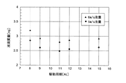
When the flying speed is 5 m / s and 6 m / s in the same recording head as in Example 1, using a water-based pigment ink, setting the preliminary pulse width to 4 AL, and changing the driving cycle as shown in FIG. The droplet mass was evaluated in the same manner as in Example 1.
駆動周期と液滴質量のグラフを図14に示す。 A graph of the driving period and the droplet mass is shown in FIG.
図14に示すように、駆動周期が長くなるにつれて小滴化する傾向が見られ、いずれの駆動周期においても、飛翔速度5m/sのほうが、6m/sよりも液滴質量が微小化していることが確認された。
<実施例4>
実施例1と同一の記録ヘッドとインクにおいて、予備パルスのパルス幅を4ALとし、非吐出画素の圧力室に予備パルスと第2のパルスからなる微振動パルスを印加する図7に示すような駆動パターンで3サイクル駆動を行い、その後図6に示す駆動信号を印加して全ノズルからインク滴を吐出させた。11℃、35%RHの低温・低湿環境におけるデキャップ特性の改善効果について評価した。
As shown in FIG. 14, there is a tendency for droplets to become smaller as the driving cycle becomes longer, and in any driving cycle, the droplet mass is smaller than that at 6 m / s at the flying speed of 5 m / s. It was confirmed.
<Example 4>
In the same recording head and ink as in the first embodiment, the pulse width of the preliminary pulse is set to 4AL, and the fine vibration pulse composed of the preliminary pulse and the second pulse is applied to the pressure chamber of the non-ejection pixel as shown in FIG. Three cycles of driving were performed with the pattern, and then a driving signal shown in FIG. 6 was applied to eject ink droplets from all nozzles. The effect of improving the decap characteristics in a low temperature and low humidity environment of 11 ° C. and 35% RH was evaluated.
デキャップ特性は任意の1ノズルについて、下記の方法を用いて測定した。 The decap characteristic was measured for any one nozzle using the following method.
デキャップ特性の測定方法
予備パルス及び吐出パルスは、実施例1と同一のパルスを用い、定常駆動時のインク滴の飛翔速度が6m/sとなる電圧に駆動電圧(Von=12.4V)を固定し、非吐出画素に微振動パルスを印加しないでその後インク滴を吐出させた条件と、全ての非吐出画素に図7の微振動パルスを印加しその後インク滴を吐出させた条件について、非吐出画素の画素数を増加させながらインク滴を吐出した時の初発速度の変化を測定した。そのときの速度変化が小さい程、大きな改善効果ありと認められる。
Measuring method of decap characteristics The same pulse as the first embodiment is used as the preliminary pulse and the ejection pulse, and the driving voltage (Von = 12.4V) is fixed to a voltage at which the flying speed of the ink droplet during steady driving is 6 m / s. The non-ejection is performed for the condition in which the ink droplet is ejected without applying the micro-vibration pulse to the non-ejection pixel and the condition in which the micro-oscillation pulse in FIG. 7 is applied to all the non-ejection pixels and then the ink droplet is ejected. Changes in the initial velocity when ink droplets were ejected while increasing the number of pixels were measured. The smaller the speed change at that time, the greater the improvement effect.
非吐出画素に微振動パルスを印加しない場合は、非吐出画素の画素数の増加にともなって初発の液滴の飛翔速度が大きく低下した。 When the fine vibration pulse was not applied to the non-ejection pixel, the flying speed of the first droplet greatly decreased as the number of non-ejection pixels increased.
非吐出画素に微振動パルスを印加した場合は、非吐出画素の画素数を増加させても初発の液滴の飛翔速度は、ほぼ6m/sであり速度低下は見られず、低温・低湿環境のデキャップ現象の防止に有効であることが確認された。また、液滴質量は2.6ngであり、定常駆動時と同じであることが確認された。 When a micro-vibration pulse is applied to a non-ejection pixel, even if the number of pixels of the non-ejection pixel is increased, the flying speed of the first droplet is almost 6 m / s, and no speed reduction is observed. It was confirmed that it is effective in preventing the decap phenomenon. The droplet mass was 2.6 ng, which was the same as that during steady driving.
非吐出画素に微振動パルスを印加するため、画像記録領域内端部のみ吐出等のパターンでも、安定した液滴形成が可能となる。また、実施例3の水系インクについてもほぼ同様の結果が得られた。 Since the micro-vibration pulse is applied to the non-ejection pixel, it is possible to form a stable droplet even with a pattern such as ejection only at the inner end of the image recording area. In addition, almost the same results were obtained with the water-based ink of Example 3.
1 インクジェット記録装置
2 記録ヘッド
4 ガイドレール
5 キャリッジ
6 フレキシブルケーブル
7、8 インク受け器
21 インクチューブ
22 ノズル形成部材
23 ノズル
24 カバープレート
25 インク供給口
26 基板
27 隔壁
28 圧力室
3 搬送機構
31 搬送ローラ
32 搬送ローラ対
33 搬送モータ
100 駆動信号生成手段
P 記録媒体
PS 記録面
DESCRIPTION OF
Claims (22)
インク滴を吐出させるために圧力発生手段に印加する駆動信号が、圧力室の容積を収縮させた後に膨張させる予備パルスと、該予備パルスの直後に印加されるとともに圧力室の容積を膨張させた後に収縮させる第1のパルスを有する吐出パルスと、を含み、
前記第1のパルスの始端が前記予備パルスの終端に直接接続されていて、
前記予備パルスはパルス幅が2AL(ALは圧力室における圧力波の音響的共振周期の1/2)以上の矩形波であることを特徴とするインクジェット記録装置。 In an inkjet recording apparatus comprising a pressure head and a pressure generating means for changing the volume of the pressure chamber, and having a recording head that discharges ink in the pressure chamber as ink droplets from a nozzle by driving the pressure generating means.
A drive signal applied to the pressure generating means for ejecting the ink droplets is applied after the volume of the pressure chamber is contracted and expanded, and immediately after the preliminary pulse , the volume of the pressure chamber is expanded. An ejection pulse having a first pulse to be subsequently contracted,
The beginning of the first pulse is directly connected to the end of the preliminary pulse;
2. The ink jet recording apparatus according to claim 1, wherein the preliminary pulse is a rectangular wave having a pulse width of 2AL (AL is 1/2 of an acoustic resonance period of the pressure wave in the pressure chamber) or more.
圧力室の容積を収縮させた後に膨張させる予備パルスと、該予備パルスの直後に印加されるとともに圧力室の容積を膨張させた後に収縮させる第1のパルスを有する吐出パルスと、を含む駆動信号を圧力発生手段に印加してインク滴を吐出させる工程を有し、
前記第1のパルスの始端が前記予備パルスの終端に直接接続されていて、
前記予備パルスはパルス幅が2AL(ALは圧力室における圧力波の音響的共振周期の1/2)以上の矩形波であることを特徴とするインクジェット記録方法。 An ink jet recording method using a recording head having a pressure chamber and pressure generating means for changing the volume of the pressure chamber, and discharging the ink in the pressure chamber as ink droplets from a nozzle by driving the pressure generating means. ,
A drive signal including a preliminary pulse that expands after the volume of the pressure chamber is contracted, and a discharge pulse that is applied immediately after the preliminary pulse and has a first pulse that contracts after the volume of the pressure chamber is expanded Applying a pressure to the pressure generating means to eject ink droplets,
The beginning of the first pulse is directly connected to the end of the preliminary pulse;
2. The ink jet recording method according to claim 1, wherein the preliminary pulse is a rectangular wave having a pulse width of 2AL (AL is 1/2 of the acoustic resonance period of the pressure wave in the pressure chamber) or more.
Priority Applications (1)
| Application Number | Priority Date | Filing Date | Title |
|---|---|---|---|
| JP2009251786A JP5458808B2 (en) | 2008-11-07 | 2009-11-02 | Inkjet recording apparatus and inkjet recording method |
Applications Claiming Priority (3)
| Application Number | Priority Date | Filing Date | Title |
|---|---|---|---|
| JP2008286249 | 2008-11-07 | ||
| JP2008286249 | 2008-11-07 | ||
| JP2009251786A JP5458808B2 (en) | 2008-11-07 | 2009-11-02 | Inkjet recording apparatus and inkjet recording method |
Publications (3)
| Publication Number | Publication Date |
|---|---|
| JP2010131988A JP2010131988A (en) | 2010-06-17 |
| JP2010131988A5 JP2010131988A5 (en) | 2012-11-29 |
| JP5458808B2 true JP5458808B2 (en) | 2014-04-02 |
Family
ID=41564007
Family Applications (1)
| Application Number | Title | Priority Date | Filing Date |
|---|---|---|---|
| JP2009251786A Expired - Fee Related JP5458808B2 (en) | 2008-11-07 | 2009-11-02 | Inkjet recording apparatus and inkjet recording method |
Country Status (4)
| Country | Link |
|---|---|
| US (1) | US8231194B2 (en) |
| EP (1) | EP2184168B1 (en) |
| JP (1) | JP5458808B2 (en) |
| AT (1) | ATE545506T1 (en) |
Families Citing this family (10)
| Publication number | Priority date | Publication date | Assignee | Title |
|---|---|---|---|---|
| WO2012081472A1 (en) * | 2010-12-16 | 2012-06-21 | コニカミノルタホールディングス株式会社 | Inkjet recording device and method for generating drive waveform signal |
| JP5861514B2 (en) * | 2012-03-14 | 2016-02-16 | コニカミノルタ株式会社 | Inkjet recording device |
| JP5861513B2 (en) * | 2012-03-14 | 2016-02-16 | コニカミノルタ株式会社 | Inkjet recording device |
| US9555628B2 (en) * | 2012-06-06 | 2017-01-31 | Panasonic Intellectual Property Management Co., Ltd. | Inkjet device, and method for manufacturing organic EL device |
| JP5768036B2 (en) * | 2012-12-11 | 2015-08-26 | 株式会社東芝 | Inkjet head drive apparatus and drive method |
| JP6365005B2 (en) * | 2013-07-30 | 2018-08-01 | セイコーエプソン株式会社 | Liquid ejecting apparatus and method for controlling liquid ejecting apparatus |
| DE102014112939A1 (en) | 2014-09-09 | 2016-03-10 | Océ Printing Systems GmbH & Co. KG | Prefire in front of pixels in an inspection mode |
| CN106335279B (en) * | 2015-07-06 | 2018-02-06 | 株式会社东芝 | Ink gun and ink-jet printer |
| CN106608100B (en) * | 2015-10-27 | 2018-09-25 | 东芝泰格有限公司 | Ink gun and ink-jet printer |
| JP2022111742A (en) * | 2021-01-20 | 2022-08-01 | 東芝テック株式会社 | Liquid discharge head |
Family Cites Families (8)
| Publication number | Priority date | Publication date | Assignee | Title |
|---|---|---|---|---|
| GB9405137D0 (en) | 1994-03-16 | 1994-04-27 | Xaar Ltd | Improvements relating to pulsed droplet deposition apparatus |
| JPH11268226A (en) | 1998-03-20 | 1999-10-05 | Dainippon Printing Co Ltd | Transfer film for lithographic press plate, forming method of lithographic press plate using the same, and lithographic press plate having formed printing area |
| JPH11268266A (en) | 1998-03-26 | 1999-10-05 | Seiko Epson Corp | Method for driving ink-jet recording apparatus |
| JP4570316B2 (en) | 2002-08-23 | 2010-10-27 | コニカミノルタホールディングス株式会社 | Ink droplet ejection device |
| JP4534504B2 (en) * | 2003-02-12 | 2010-09-01 | コニカミノルタホールディングス株式会社 | Droplet discharge apparatus and droplet discharge head driving method |
| US7195327B2 (en) * | 2003-02-12 | 2007-03-27 | Konica Minolta Holdings, Inc. | Droplet ejection apparatus and its drive method |
| JP4474987B2 (en) * | 2004-04-23 | 2010-06-09 | コニカミノルタホールディングス株式会社 | Driving method of droplet discharge head |
| JP2007022073A (en) | 2005-06-16 | 2007-02-01 | Toshiba Tec Corp | Inkjet head driving method and driver |
-
2009
- 2009-10-29 EP EP09252499A patent/EP2184168B1/en not_active Not-in-force
- 2009-10-29 US US12/608,221 patent/US8231194B2/en active Active
- 2009-10-29 AT AT09252499T patent/ATE545506T1/en active
- 2009-11-02 JP JP2009251786A patent/JP5458808B2/en not_active Expired - Fee Related
Also Published As
| Publication number | Publication date |
|---|---|
| JP2010131988A (en) | 2010-06-17 |
| EP2184168B1 (en) | 2012-02-15 |
| US8231194B2 (en) | 2012-07-31 |
| ATE545506T1 (en) | 2012-03-15 |
| US20100118073A1 (en) | 2010-05-13 |
| EP2184168A1 (en) | 2010-05-12 |
Similar Documents
| Publication | Publication Date | Title |
|---|---|---|
| JP5458808B2 (en) | Inkjet recording apparatus and inkjet recording method | |
| WO2000044564A1 (en) | Ink jet recording head driving method and ink jet recording device | |
| JP5867072B2 (en) | Droplet ejection device and method for driving droplet ejection device | |
| JP4534504B2 (en) | Droplet discharge apparatus and droplet discharge head driving method | |
| JP6575534B2 (en) | Droplet discharge head driving method and droplet discharge apparatus | |
| JP6149863B2 (en) | Ink jet head driving method, ink jet head driving apparatus, and ink jet recording apparatus | |
| JP4631285B2 (en) | Inkjet recording apparatus and inkjet recording method | |
| JP5440412B2 (en) | Ink jet recording apparatus and recording head driving method | |
| US7862135B2 (en) | Method of driving liquid ejecting head and liquid ejecting apparatus | |
| JP4196704B2 (en) | Inkjet recording device | |
| JP5282301B2 (en) | Liquid ejection device | |
| JP4570316B2 (en) | Ink droplet ejection device | |
| JP5304498B2 (en) | Inkjet recording device | |
| JP4474988B2 (en) | Driving method of droplet discharge head | |
| JP5440392B2 (en) | Inkjet recording device | |
| JP4449473B2 (en) | Inkjet recording device | |
| JP4207551B2 (en) | Inkjet recording device | |
| JP6512036B2 (en) | Liquid discharge device | |
| JP3362732B2 (en) | Inkjet head driving method | |
| JP7188551B2 (en) | Method for driving droplet ejection head | |
| JP3785058B2 (en) | Ink jet apparatus and ink jet head driving method | |
| JP4474986B2 (en) | Driving method of droplet discharge head | |
| JP6680129B2 (en) | Ink jet recording apparatus and ink jet recording method | |
| JP4656207B2 (en) | Inkjet recording device | |
| JP2016087918A (en) | Driving method of inkjet head and inkjet recording device |
Legal Events
| Date | Code | Title | Description |
|---|---|---|---|
| A521 | Request for written amendment filed |
Free format text: JAPANESE INTERMEDIATE CODE: A523 Effective date: 20121015 |
|
| A621 | Written request for application examination |
Free format text: JAPANESE INTERMEDIATE CODE: A621 Effective date: 20121015 |
|
| RD02 | Notification of acceptance of power of attorney |
Free format text: JAPANESE INTERMEDIATE CODE: A7422 Effective date: 20121015 |
|
| A711 | Notification of change in applicant |
Free format text: JAPANESE INTERMEDIATE CODE: A712 Effective date: 20130417 |
|
| A131 | Notification of reasons for refusal |
Free format text: JAPANESE INTERMEDIATE CODE: A131 Effective date: 20130702 |
|
| A131 | Notification of reasons for refusal |
Free format text: JAPANESE INTERMEDIATE CODE: A131 Effective date: 20130924 |
|
| A521 | Request for written amendment filed |
Free format text: JAPANESE INTERMEDIATE CODE: A523 Effective date: 20131125 |
|
| TRDD | Decision of grant or rejection written | ||
| A01 | Written decision to grant a patent or to grant a registration (utility model) |
Free format text: JAPANESE INTERMEDIATE CODE: A01 Effective date: 20131217 |
|
| A61 | First payment of annual fees (during grant procedure) |
Free format text: JAPANESE INTERMEDIATE CODE: A61 Effective date: 20131230 |
|
| R150 | Certificate of patent or registration of utility model |
Ref document number: 5458808 Country of ref document: JP Free format text: JAPANESE INTERMEDIATE CODE: R150 Free format text: JAPANESE INTERMEDIATE CODE: R150 |
|
| LAPS | Cancellation because of no payment of annual fees |