EP3243431A1 - A strap for a portable pulse measuring device and a portable pulse measuring device - Google Patents
A strap for a portable pulse measuring device and a portable pulse measuring device Download PDFInfo
- Publication number
- EP3243431A1 EP3243431A1 EP17179049.6A EP17179049A EP3243431A1 EP 3243431 A1 EP3243431 A1 EP 3243431A1 EP 17179049 A EP17179049 A EP 17179049A EP 3243431 A1 EP3243431 A1 EP 3243431A1
- Authority
- EP
- European Patent Office
- Prior art keywords
- strap
- measuring device
- pulse measuring
- indicator
- portable pulse
- Prior art date
- Legal status (The legal status is an assumption and is not a legal conclusion. Google has not performed a legal analysis and makes no representation as to the accuracy of the status listed.)
- Granted
Links
- 238000005259 measurement Methods 0.000 description 6
- 210000000707 wrist Anatomy 0.000 description 5
- 238000009940 knitting Methods 0.000 description 4
- 230000003287 optical effect Effects 0.000 description 3
- 230000017531 blood circulation Effects 0.000 description 2
- 238000009532 heart rate measurement Methods 0.000 description 2
- 238000005516 engineering process Methods 0.000 description 1
- 230000031700 light absorption Effects 0.000 description 1
- 239000000463 material Substances 0.000 description 1
- 238000000034 method Methods 0.000 description 1
- 238000012806 monitoring device Methods 0.000 description 1
Images

Classifications
-
- G—PHYSICS
- G04—HOROLOGY
- G04G—ELECTRONIC TIME-PIECES
- G04G17/00—Structural details; Housings
- G04G17/02—Component assemblies
-
- A—HUMAN NECESSITIES
- A61—MEDICAL OR VETERINARY SCIENCE; HYGIENE
- A61B—DIAGNOSIS; SURGERY; IDENTIFICATION
- A61B5/00—Measuring for diagnostic purposes; Identification of persons
- A61B5/68—Arrangements of detecting, measuring or recording means, e.g. sensors, in relation to patient
- A61B5/6801—Arrangements of detecting, measuring or recording means, e.g. sensors, in relation to patient specially adapted to be attached to or worn on the body surface
- A61B5/6843—Monitoring or controlling sensor contact pressure
-
- A—HUMAN NECESSITIES
- A61—MEDICAL OR VETERINARY SCIENCE; HYGIENE
- A61B—DIAGNOSIS; SURGERY; IDENTIFICATION
- A61B5/00—Measuring for diagnostic purposes; Identification of persons
- A61B5/02—Detecting, measuring or recording pulse, heart rate, blood pressure or blood flow; Combined pulse/heart-rate/blood pressure determination; Evaluating a cardiovascular condition not otherwise provided for, e.g. using combinations of techniques provided for in this group with electrocardiography or electroauscultation; Heart catheters for measuring blood pressure
- A61B5/024—Detecting, measuring or recording pulse rate or heart rate
-
- A—HUMAN NECESSITIES
- A44—HABERDASHERY; JEWELLERY
- A44B—BUTTONS, PINS, BUCKLES, SLIDE FASTENERS, OR THE LIKE
- A44B11/00—Buckles; Similar fasteners for interconnecting straps or the like, e.g. for safety belts
-
- A—HUMAN NECESSITIES
- A61—MEDICAL OR VETERINARY SCIENCE; HYGIENE
- A61B—DIAGNOSIS; SURGERY; IDENTIFICATION
- A61B5/00—Measuring for diagnostic purposes; Identification of persons
- A61B5/02—Detecting, measuring or recording pulse, heart rate, blood pressure or blood flow; Combined pulse/heart-rate/blood pressure determination; Evaluating a cardiovascular condition not otherwise provided for, e.g. using combinations of techniques provided for in this group with electrocardiography or electroauscultation; Heart catheters for measuring blood pressure
- A61B5/024—Detecting, measuring or recording pulse rate or heart rate
- A61B5/02416—Detecting, measuring or recording pulse rate or heart rate using photoplethysmograph signals, e.g. generated by infrared radiation
- A61B5/02422—Detecting, measuring or recording pulse rate or heart rate using photoplethysmograph signals, e.g. generated by infrared radiation within occluders
-
- A—HUMAN NECESSITIES
- A61—MEDICAL OR VETERINARY SCIENCE; HYGIENE
- A61B—DIAGNOSIS; SURGERY; IDENTIFICATION
- A61B5/00—Measuring for diagnostic purposes; Identification of persons
- A61B5/02—Detecting, measuring or recording pulse, heart rate, blood pressure or blood flow; Combined pulse/heart-rate/blood pressure determination; Evaluating a cardiovascular condition not otherwise provided for, e.g. using combinations of techniques provided for in this group with electrocardiography or electroauscultation; Heart catheters for measuring blood pressure
- A61B5/024—Detecting, measuring or recording pulse rate or heart rate
- A61B5/02438—Detecting, measuring or recording pulse rate or heart rate with portable devices, e.g. worn by the patient
-
- G—PHYSICS
- G04—HOROLOGY
- G04G—ELECTRONIC TIME-PIECES
- G04G21/00—Input or output devices integrated in time-pieces
- G04G21/02—Detectors of external physical values, e.g. temperature
- G04G21/025—Detectors of external physical values, e.g. temperature for measuring physiological data
-
- A—HUMAN NECESSITIES
- A61—MEDICAL OR VETERINARY SCIENCE; HYGIENE
- A61B—DIAGNOSIS; SURGERY; IDENTIFICATION
- A61B5/00—Measuring for diagnostic purposes; Identification of persons
- A61B5/68—Arrangements of detecting, measuring or recording means, e.g. sensors, in relation to patient
- A61B5/6801—Arrangements of detecting, measuring or recording means, e.g. sensors, in relation to patient specially adapted to be attached to or worn on the body surface
- A61B5/6813—Specially adapted to be attached to a specific body part
- A61B5/6824—Arm or wrist
Definitions
- the invention relates to a strap for a portable pulse measuring device and to a portable pulse measuring device comprising a strap.
- Pulse can be measured using, for example, portable pulse measuring devices.
- a portable pulse measuring device may measure pulse optically.
- Another possibility is to use a separate heart rate belt around one's chest, and the belt then transmits measured pulse signals wirelessly to a monitoring device, for example, attached on a wrist or to an application running in a mobile phone.
- the optical pulse measurement is based on the fact that light is emitted by a light source towards body tissue and at least one detector is configured to detect the intensity of reflected light after propagation through the human body tissue.
- the optical measurement is based on light absorption changes caused by blood flow in a lighted area. If the shape of the lighted area changes during the measurement, for example, due to movement of the pulse measuring device, the measurement is disturbed. Thus, for example, movements of a hand and of a human cause errors to the measurement in many ways.
- the portable pulse device needs to be as stable as possible in relation to skin and needs to minimize mechanical changes in tissue area during movement.
- One solution is to tighten a strap of pulse a measuring device more.
- the problem is that a user may tighten the strap too much, which in turn is uncomfortable and prevents blood flow in tissue.
- too loose tightening of the strap allows the portable pulse measuring device to move too much in relation, for example, to a wrist and body tissue.
- a strap for a portable pulse measuring device comprising an indicator configured to indicate tightness of the strap.
- the strap is a stretchable strap comprising a non-stretchable sliding part built-in in the stretchable strap, wherein the stretchable strap comprises a section through which the indicator on the non-stretchable sliding part is visible.
- the strap is a stretchable strap comprising a stretchable sliding part built-in in the stretchable strap, the stretchable sliding part being less stretchable than the stretchable strap, wherein the stretchable strap comprises a section through which the indicator on the stretchable sliding part is visible.
- the indicator is provided by knitting the strap such that it provides a meter showing the level of tightness of the strap.
- a portable pulse measuring device comprising a strap configured to fasten the portable pulse measuring device on a human; and a mechanical indicator configured to indicate tightness of the strap.
- the mechanical indicator is arranged into a link part connected to a main body of the portable pulse measuring device and to which the strap is attached.
- the link part comprises a window in which the mechanical indicator is movable to indicate the tightness of the strap.
- the link part comprises a rotating part to which the strap is attached.
- the indicator is attached to the rotating part such the when the rotating part rotates, the indicator moves in the window.
- the link part comprises a sliding part to which the strap is attached.
- the indicator is attached to the sliding part such that when the sliding part moves, the indicator moves in the window.
- a strap for a portable pulse measuring device wherein the strap comprises an indicator configured to indicate tightness of the strap, wherein the strap is a stretchable strap comprising a non-stretchable sliding part built-in in the stretchable strap and wherein the stretchable strap comprises a section through which the indicator on the non-stretchable sliding part is visible.
- a strap for a portable pulse measuring device comprising: an indicator configured to indicate tightness of the strap, wherein the strap is a stretchable strap comprising a stretchable sliding part built-in in the stretchable strap, the stretchable sliding part being less stretchable than the stretchable stra and wherein the stretchable strap comprises a section through which the indicator on the stretchable sliding part is visible.
- a strap for a portable pulse measuring device wherein the strap comprises an indicator configured to indicate tightness of the strap, wherein the indicator is provided by knitting the strap such that it provides a meter showing the level of tightness of the strap.
- a portable pulse measuring device comprising a strap configured to fasten the portable pulse measuring device on a human; and a link part, wherein the strap is connected to the link part and wherein the link part comprises a mechanical indicator configured to indicate tightness of the strap.
- a portable pulse measuring device comprising a strap according to any of the above aspects to fasten the portable pulse measuring device on a human.
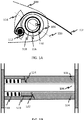
- Figure 1A discloses an arrangement comprising a mechanical indicator configured to indicate tightness of a strap 102 of a portable pulse measuring device according to one embodiment of the invention.
- a link part 100 of the portable pulse measuring device provides an attachment point to a strap 102.
- the link part 100 may be removably attachable to a main body (not shown) of the portable pulse measuring device, or alternatively, the link part 100 may be an integral part of the main body.
- the link part 100 includes a fixed axle 106.
- a sliding part and a resilient member, for example a spring 108, are arranged around the fixed axle 104. Instead of the spring, any other resilient member may be used.
- a rotation blocker 110 is attached to the sliding part 108 in order to prevent the sliding part 108 to rotate around the fixed axle 106.
- a rotating non-sliding part 104 is arranged as an outmost element and the strap 102 is in contact with the rotating non-sliding part 104 in a section of its circumference, as illustrated in Figure 1A .
- Reference number 112 indicates that the strap 102 is attached to the rotating non-sliding part 104.
- the link part 100 includes a window 114, for example a hole, in which an indicator is movable and the location of the indicator in the hole 114 depends on the tightness of the strap 102 when a user of the portable pulse measuring device fastens the device, for example, around his wrist.
- the indicator is attached to the rotating non-sliding part 104 and thus it moves when the rotating non-sliding part 104 rotates.
- the indicator may be a peg which moves in the window 114.
- the indicator is a plate movable in the window 114 and it comprises a scale.
- a pointer has been arranged in the link part 100. When the plate moves as a result of pulling the strap, the pointer points to a certain point in the scale on the plate.
- the hole 114 may take a form of a slot which is radially arranged in relation to the fixed axle 106.
- Reference number 116 refers to a cross-section which is illustrated in more detail in Figure 1B .
- the window 114 is a hole in the link part.
- the link part 100 comprises transparent section through which the indicator can be seen.
- the link part 100 may be partly or wholly made of plastic and it may be partly or wholly transparent.
- Figure 1B discloses a cross-section view of the arrangement of Figure 1A .
- the rotating non-sliding part 104 partially directly surrounds the fixed axle 106 and is arranged to be rotatable about the fixed axle 106.
- the remaining part of the fixed axle 106 not directly surrounded by the rotating non-sliding part 104 is occupied by a spring 118 and a non-rotating sliding part 120.
- the spring 118 presses the sliding non-rotating part 120 and the sliding non-rotating part 120 generates a rotating force for the rotating non-sliding part 104 and thus the rotating non-sliding part 104 turns to its relaxed position.
- Figure 2 discloses an arrangement comprising a mechanical indicator configured to indicate tightness of a strap 202 of a portable pulse measuring device according to one embodiment of the invention.
- Figure 1A disclosed a turning force indicator
- Figure 2 discloses a sliding force indicator.
- a link part 200 of the portable pulse measuring device provides an attachment point to the strap 202.
- the link part 200 may be removably attachable to a main body (not shown) of the portable pulse measuring device or alternatively the link part 200 may be an integral part of the main body.
- the link part 200 includes a fixed axle 216.
- a rotating part 214 is arranged to be rotatably attached to the fixed axle 216.
- the strap 202 is arranged to be partially in contact with the rotating part 214 on the circumference of the rotating part 214, as disclosed in Figure 2 .
- a sliding part 204 is arranged in the link part 200 and the strap 202 is attached to the sliding part 204.
- a first spring blocker 208 is arranged in the link part 200 and a second spring blocker is arranged in the sliding part 204.
- a spring 206 is arranged between the first spring blocker 208 and the second spring blocker 210.
- the sliding part 204 comprises guiders which keep the sliding part 204 on its sliding track in the link part 200. When the strap 202 is pulled, the sliding part 204 moves and the spring 206 compresses. Instead of the spring 206, any other resilient member may be used.
- the link part 200 also includes a window 212 through which an indicator 218 in the sliding part 204 or attached to the sliding part 204 can be seen.
- the window 212 is a hole in the link part 200.
- the link part 200 comprises a transparent section through which the indicator in the sliding part 204 or attached to the sliding part 204 can be seen.
- the link part 200 may be partly or wholly made of plastic. Furthermore, it may be partly or wholly transparent.
- Figure 2 discloses that the sliding part includes three patterns for indicating the tightness of the strap 202. Only one pattern can be seen in whole at a time through the window 212 in the link part 200. It is evident that Figure 2 discloses only one example of a possible indicator.
- an elongated slot may be arranged in the link part 200 and an indicator attached to the sliding part 204 moves in the elongated slot and indicates the current tightness of the strap 202.
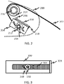
- Figure 3 discloses a strap 300 for a portable pulse measuring device according to one embodiment of the invention.
- the strap 300 and a sliding part 302 are attached to a fixation part 304 via which they can be attached to a portable pulse measuring device body part.
- an indicator 310 indicating tightness of the strap 300 is included in the strap 300 itself.
- the strap 300 is stretchable.
- a sliding part 302 that is not stretchable, or has different stretching properties than the stretchable strap 300, is built-in in the stretchable strap 300.
- the sliding part 302 is configured in the stretchable strap 300 so that when the strap 300 stretches, the sliding part 302 remains unstretched.
- a cavity may be arranged in the strap 300 for the sliding part so that the sliding part 302 does not move when the strap 300 is stretched.
- the sliding part 302 has been equipped with one or more patterns, i.e. indicators 310, to indicate the tightness of the strap.
- the strap When the strap is pulled (i.e. when a user fastens the portable pulse measuring device comprising the strap, for example, onto his wrist and tightens the strap), the strap stretches and an indicator hole 308 moves in relation to the non-stretchable sliding part 302. A pattern indicating the tightness of the strap 300 is then visible via the hole 308.
- the strap 300 is a stretchable strap comprising a sliding part 302 built-in in the stretchable strap 300.
- the sliding part 302 is stretchable but less stretchable than the stretchable strap 300.
- the strap 300 when the strap 300 is pulled (i.e. when a user fastens the portable pulse measuring device comprising the strap, for example, onto his wrist and tightens the strap), the strap 300 stretches, and at the same time, also the sliding part 302 stretches but less than the strap 300.
- An indicator hole 308 arranged in the strap 300 moves in relation to the sliding part 302, and an indicator 310 is visible through the indicator hole 308.
- Figure 4 discloses a strap 400 for a portable pulse measuring device according to one embodiment of the invention.
- the strap 400 of the embodiment of Figure 4 is stretchable.
- the strap 400 has been specially configured so that when the strap 400 is stretched, it shows a meter 404 showing the tension level of the strap 400.
- the strap 400 may include a numerical scale 402 or some other type of a scale or pattern to provide information about the tension/tightness of the strap 400.
- the meter 404 can be achieved, for example, by a special knitting of the strap 400 wholly or partially. When the strap 400 is stretched, the special knitting enables the meter 404 to be seen indicating the tension/tightness of the strap 400.
- a benefit of the embodiments disclosed in Figures 1A, 1B and 2-4 is that the guided adjustment of tightness of the strap enables the use of the portable pulse measuring device in various operating situations. Moreover, the solution enables optimal strap tightness and avoids excessive loosening or tightening. Furthermore, the disclosed solution also takes into account physiological variations between individuals. Furthermore, the embodiments disclosed in Figures 1A, 1B and 2-4 are also advantageous when measuring pulse with pulse measuring devices that use optical pulse measurement techniques since undesired movements of the device may cause disturbances in the measurements. With the disclosed embodiments it is possible to ensure optimal strap tightness of the strap.
Landscapes
- Health & Medical Sciences (AREA)
- Life Sciences & Earth Sciences (AREA)
- Cardiology (AREA)
- Physics & Mathematics (AREA)
- General Health & Medical Sciences (AREA)
- Biophysics (AREA)
- Medical Informatics (AREA)
- Animal Behavior & Ethology (AREA)
- Biomedical Technology (AREA)
- Heart & Thoracic Surgery (AREA)
- Pathology (AREA)
- Molecular Biology (AREA)
- Surgery (AREA)
- Engineering & Computer Science (AREA)
- Veterinary Medicine (AREA)
- Public Health (AREA)
- Physiology (AREA)
- Dentistry (AREA)
- Vascular Medicine (AREA)
- General Physics & Mathematics (AREA)
- Measuring Pulse, Heart Rate, Blood Pressure Or Blood Flow (AREA)
- Purses, Travelling Bags, Baskets, Or Suitcases (AREA)
Abstract
Description
- The invention relates to a strap for a portable pulse measuring device and to a portable pulse measuring device comprising a strap.
- Pulse can be measured using, for example, portable pulse measuring devices. A portable pulse measuring device may measure pulse optically. Another possibility is to use a separate heart rate belt around one's chest, and the belt then transmits measured pulse signals wirelessly to a monitoring device, for example, attached on a wrist or to an application running in a mobile phone.
- The optical pulse measurement is based on the fact that light is emitted by a light source towards body tissue and at least one detector is configured to detect the intensity of reflected light after propagation through the human body tissue. There are several challenges when measuring pulse optically. The optical measurement is based on light absorption changes caused by blood flow in a lighted area. If the shape of the lighted area changes during the measurement, for example, due to movement of the pulse measuring device, the measurement is disturbed. Thus, for example, movements of a hand and of a human cause errors to the measurement in many ways. In order to avoid problems in the measurement, the portable pulse device needs to be as stable as possible in relation to skin and needs to minimize mechanical changes in tissue area during movement.
- There are many ways to address the above problems. One solution is to tighten a strap of pulse a measuring device more. The problem, however, is that a user may tighten the strap too much, which in turn is uncomfortable and prevents blood flow in tissue. In turn, too loose tightening of the strap allows the portable pulse measuring device to move too much in relation, for example, to a wrist and body tissue.
- It is possible to solve the above problems by design, for example, by making the device light, by optimizing the friction between skin and the device by material selection, or by making the device or strap of the device wider. Although these aspects may alleviate the problems in some cases, the basic problem still remains - how to provide an optimal strap tightening for a strap of a pulse measuring device.
- According to one aspect, there is provided a strap for a portable pulse measuring device. The strap comprises an indicator configured to indicate tightness of the strap.
- In one embodiment the strap is a stretchable strap comprising a non-stretchable sliding part built-in in the stretchable strap, wherein the stretchable strap comprises a section through which the indicator on the non-stretchable sliding part is visible.
- In one embodiment the strap is a stretchable strap comprising a stretchable sliding part built-in in the stretchable strap, the stretchable sliding part being less stretchable than the stretchable strap, wherein the stretchable strap comprises a section through which the indicator on the stretchable sliding part is visible.
- In one embodiment the indicator is provided by knitting the strap such that it provides a meter showing the level of tightness of the strap.
- According to another aspect, there is provided a portable pulse measuring device comprising a strap configured to fasten the portable pulse measuring device on a human; and a mechanical indicator configured to indicate tightness of the strap.
- In one embodiment the mechanical indicator is arranged into a link part connected to a main body of the portable pulse measuring device and to which the strap is attached.
- In one embodiment the link part comprises a window in which the mechanical indicator is movable to indicate the tightness of the strap.
- In one embodiment the link part comprises a rotating part to which the strap is attached. The indicator is attached to the rotating part such the when the rotating part rotates, the indicator moves in the window.
- In one embodiment the link part comprises a sliding part to which the strap is attached. The indicator is attached to the sliding part such that when the sliding part moves, the indicator moves in the window.
- According to another aspect, there is provided a strap for a portable pulse measuring device, wherein the strap comprises an indicator configured to indicate tightness of the strap, wherein the strap is a stretchable strap comprising a non-stretchable sliding part built-in in the stretchable strap and wherein the stretchable strap comprises a section through which the indicator on the non-stretchable sliding part is visible.
- According to another aspect, there is provided a strap for a portable pulse measuring device, wherein the strap comprises: an indicator configured to indicate tightness of the strap, wherein the strap is a stretchable strap comprising a stretchable sliding part built-in in the stretchable strap, the stretchable sliding part being less stretchable than the stretchable stra and wherein the stretchable strap comprises a section through which the indicator on the stretchable sliding part is visible.
- According to another aspect, there is provided a strap for a portable pulse measuring device, wherein the strap comprises an indicator configured to indicate tightness of the strap, wherein the indicator is provided by knitting the strap such that it provides a meter showing the level of tightness of the strap.
- According to another aspect, there is provided a portable pulse measuring device comprising a strap configured to fasten the portable pulse measuring device on a human; and a link part, wherein the strap is connected to the link part and wherein the link part comprises a mechanical indicator configured to indicate tightness of the strap.
- According to another aspect, there is provided a portable pulse measuring device comprising a strap according to any of the above aspects to fasten the portable pulse measuring device on a human.
- The accompanying drawings, which are included to provide a further understanding of the invention and constitute a part of this specification, illustrate embodiments of the invention and together with the description help to explain the principles of the invention. In the drawings:
-
Figure 1A discloses an arrangement comprising a mechanical indicator configured to indicate tightness of a strap of a portable pulse measuring device according to one embodiment of the invention. -
Figure 1B discloses a cross-section view of the arrangement ofFigure 1A . -
Figure 2 discloses an arrangement comprising a mechanical indicator configured to indicate tightness of a strap of a portable pulse measuring device according to one embodiment of the invention. -
Figure 3 discloses a strap for a portable pulse measuring device according to one embodiment of the invention. -
Figure 4 discloses a strap for a portable pulse measuring device according to one embodiment of the invention. -
Figure 1A discloses an arrangement comprising a mechanical indicator configured to indicate tightness of astrap 102 of a portable pulse measuring device according to one embodiment of the invention. - A
link part 100 of the portable pulse measuring device provides an attachment point to astrap 102. Thelink part 100 may be removably attachable to a main body (not shown) of the portable pulse measuring device, or alternatively, thelink part 100 may be an integral part of the main body. Thelink part 100 includes afixed axle 106. A sliding part and a resilient member, for example aspring 108, are arranged around thefixed axle 104. Instead of the spring, any other resilient member may be used. Arotation blocker 110 is attached to thesliding part 108 in order to prevent thesliding part 108 to rotate around thefixed axle 106. A rotatingnon-sliding part 104 is arranged as an outmost element and thestrap 102 is in contact with the rotatingnon-sliding part 104 in a section of its circumference, as illustrated inFigure 1A .Reference number 112 indicates that thestrap 102 is attached to the rotatingnon-sliding part 104. Thelink part 100 includes awindow 114, for example a hole, in which an indicator is movable and the location of the indicator in thehole 114 depends on the tightness of thestrap 102 when a user of the portable pulse measuring device fastens the device, for example, around his wrist. - In one embodiment, the indicator is attached to the
rotating non-sliding part 104 and thus it moves when therotating non-sliding part 104 rotates. The indicator may be a peg which moves in thewindow 114. In another embodiment, the indicator is a plate movable in thewindow 114 and it comprises a scale. A pointer has been arranged in thelink part 100. When the plate moves as a result of pulling the strap, the pointer points to a certain point in the scale on the plate. - As illustrated in
Figure 1A , thehole 114 may take a form of a slot which is radially arranged in relation to thefixed axle 106.Reference number 116 refers to a cross-section which is illustrated in more detail inFigure 1B . - In one embodiment, the
window 114 is a hole in the link part. In another embodiment, thelink part 100 comprises transparent section through which the indicator can be seen. For example, thelink part 100 may be partly or wholly made of plastic and it may be partly or wholly transparent. -
Figure 1B discloses a cross-section view of the arrangement ofFigure 1A . As illustrated inFigure 1B the rotatingnon-sliding part 104 partially directly surrounds the fixedaxle 106 and is arranged to be rotatable about the fixedaxle 106. The remaining part of the fixedaxle 106 not directly surrounded by the rotatingnon-sliding part 104 is occupied by aspring 118 and anon-rotating sliding part 120. - When the
strap 102 is pulled the rotatingnon-sliding part 104 rotates around the fixedaxle 106. Aninclined surface 122 of the rotatingnon-sliding part 104 faces towards aninclined surface 124 of the slidingnon-rotating part 120. When the rotatingnon-sliding part 104 rotates it presses the slidingnon-rotating part 120, and due to theinclined surfaces non-rotating part 120 moves and compresses thespring 118. Although not illustrated inFigure 1B , this action also moves the indicator in thehole 114. When the pulling stops and the tightness of thestrap 102 is reduced, thespring 118 presses the slidingnon-rotating part 120 and the slidingnon-rotating part 120 generates a rotating force for the rotatingnon-sliding part 104 and thus the rotatingnon-sliding part 104 turns to its relaxed position. -
Figure 2 discloses an arrangement comprising a mechanical indicator configured to indicate tightness of astrap 202 of a portable pulse measuring device according to one embodiment of the invention. WhereasFigure 1A disclosed a turning force indicatorFigure 2 discloses a sliding force indicator. - A
link part 200 of the portable pulse measuring device provides an attachment point to thestrap 202. Thelink part 200 may be removably attachable to a main body (not shown) of the portable pulse measuring device or alternatively thelink part 200 may be an integral part of the main body. Thelink part 200 includes a fixedaxle 216. Arotating part 214 is arranged to be rotatably attached to the fixedaxle 216. Thestrap 202 is arranged to be partially in contact with therotating part 214 on the circumference of therotating part 214, as disclosed inFigure 2 . A slidingpart 204 is arranged in thelink part 200 and thestrap 202 is attached to the slidingpart 204. - A
first spring blocker 208 is arranged in thelink part 200 and a second spring blocker is arranged in the slidingpart 204. Aspring 206 is arranged between thefirst spring blocker 208 and thesecond spring blocker 210. In one embodiment, the slidingpart 204 comprises guiders which keep the slidingpart 204 on its sliding track in thelink part 200. When thestrap 202 is pulled, the slidingpart 204 moves and thespring 206 compresses. Instead of thespring 206, any other resilient member may be used. - The
link part 200 also includes awindow 212 through which anindicator 218 in the slidingpart 204 or attached to the slidingpart 204 can be seen. In one embodiment, thewindow 212 is a hole in thelink part 200. In another embodiment, thelink part 200 comprises a transparent section through which the indicator in the slidingpart 204 or attached to the slidingpart 204 can be seen. For example, thelink part 200 may be partly or wholly made of plastic. Furthermore, it may be partly or wholly transparent. - As an example of the indicator,
Figure 2 discloses that the sliding part includes three patterns for indicating the tightness of thestrap 202. Only one pattern can be seen in whole at a time through thewindow 212 in thelink part 200. It is evident thatFigure 2 discloses only one example of a possible indicator. In another embodiment, an elongated slot may be arranged in thelink part 200 and an indicator attached to the slidingpart 204 moves in the elongated slot and indicates the current tightness of thestrap 202. -
Figure 3 discloses astrap 300 for a portable pulse measuring device according to one embodiment of the invention. Thestrap 300 and a slidingpart 302 are attached to afixation part 304 via which they can be attached to a portable pulse measuring device body part. In the embodiment disclosed inFigure 3 , an indicator 310 indicating tightness of thestrap 300 is included in thestrap 300 itself. Thestrap 300 is stretchable. A slidingpart 302 that is not stretchable, or has different stretching properties than thestretchable strap 300, is built-in in thestretchable strap 300. The slidingpart 302 is configured in thestretchable strap 300 so that when thestrap 300 stretches, the slidingpart 302 remains unstretched. In other words, to achieve this functionality a cavity may be arranged in thestrap 300 for the sliding part so that the slidingpart 302 does not move when thestrap 300 is stretched. The slidingpart 302 has been equipped with one or more patterns, i.e. indicators 310, to indicate the tightness of the strap. - When the strap is pulled (i.e. when a user fastens the portable pulse measuring device comprising the strap, for example, onto his wrist and tightens the strap), the strap stretches and an indicator hole 308 moves in relation to the
non-stretchable sliding part 302. A pattern indicating the tightness of thestrap 300 is then visible via the hole 308. - In another embodiment of
Figure 3 , thestrap 300 is a stretchable strap comprising a slidingpart 302 built-in in thestretchable strap 300. The slidingpart 302, however, is stretchable but less stretchable than thestretchable strap 300. In other words, when thestrap 300 is pulled (i.e. when a user fastens the portable pulse measuring device comprising the strap, for example, onto his wrist and tightens the strap), thestrap 300 stretches, and at the same time, also the slidingpart 302 stretches but less than thestrap 300. An indicator hole 308 arranged in thestrap 300 moves in relation to the slidingpart 302, and an indicator 310 is visible through the indicator hole 308. -
Figure 4 discloses astrap 400 for a portable pulse measuring device according to one embodiment of the invention. As in the embodiment ofFigure 3 , thestrap 400 of the embodiment ofFigure 4 is stretchable. Thestrap 400 has been specially configured so that when thestrap 400 is stretched, it shows ameter 404 showing the tension level of thestrap 400. Thestrap 400 may include anumerical scale 402 or some other type of a scale or pattern to provide information about the tension/tightness of thestrap 400. Themeter 404 can be achieved, for example, by a special knitting of thestrap 400 wholly or partially. When thestrap 400 is stretched, the special knitting enables themeter 404 to be seen indicating the tension/tightness of thestrap 400. - A benefit of the embodiments disclosed in
Figures 1A, 1B and2-4 is that the guided adjustment of tightness of the strap enables the use of the portable pulse measuring device in various operating situations. Moreover, the solution enables optimal strap tightness and avoids excessive loosening or tightening. Furthermore, the disclosed solution also takes into account physiological variations between individuals. Furthermore, the embodiments disclosed inFigures 1A, 1B and2-4 are also advantageous when measuring pulse with pulse measuring devices that use optical pulse measurement techniques since undesired movements of the device may cause disturbances in the measurements. With the disclosed embodiments it is possible to ensure optimal strap tightness of the strap. - It is obvious to a person skilled in the art that with the advancement of technology, the basic idea of the invention may be implemented in various ways. The invention and its embodiments are thus not limited to the examples described above, instead they may vary within the scope of the claims.
Claims (4)
- A portable pulse measuring device comprising:a main body comprising a link part;a strap configured to fasten the portable pulse measuring device on a human; andwherein the strap is connected to the link part and wherein the link part comprises a mechanical indicator configured to indicate tightness of the strap.
- The portable pulse measuring device according to claim 1, wherein the link part comprises a window in which the mechanical indicator is movable to indicate the tightness of the strap.
- The portable pulse measuring device according to claim 2, wherein the link part comprises a rotating part to which the strap is attached, and wherein the indicator is attached to the rotating part such the when the rotating part rotates, the indicator moves in the window.
- The portable pulse measuring device according to claim 2, wherein the link part comprises a sliding part to which the strap is attached, and wherein the indicator is attached to the sliding part such that when the sliding part moves, the indicator moves in the window.
Applications Claiming Priority (3)
| Application Number | Priority Date | Filing Date | Title |
|---|---|---|---|
| FI20135640A FI126165B (en) | 2013-06-11 | 2013-06-11 | Strap for portable heart rate monitor and portable heart rate monitor |
| PCT/FI2014/050471 WO2014199017A1 (en) | 2013-06-11 | 2014-06-11 | A strap for a portable pulse measuring device and a portable pulse measuring device |
| EP14811340.0A EP3007617A4 (en) | 2013-06-11 | 2014-06-11 | A strap for a portable pulse measuring device and a portable pulse measuring device |
Related Parent Applications (1)
| Application Number | Title | Priority Date | Filing Date |
|---|---|---|---|
| EP14811340.0A Division EP3007617A4 (en) | 2013-06-11 | 2014-06-11 | A strap for a portable pulse measuring device and a portable pulse measuring device |
Publications (2)
| Publication Number | Publication Date |
|---|---|
| EP3243431A1 true EP3243431A1 (en) | 2017-11-15 |
| EP3243431B1 EP3243431B1 (en) | 2021-04-28 |
Family
ID=52021704
Family Applications (2)
| Application Number | Title | Priority Date | Filing Date |
|---|---|---|---|
| EP14811340.0A Withdrawn EP3007617A4 (en) | 2013-06-11 | 2014-06-11 | A strap for a portable pulse measuring device and a portable pulse measuring device |
| EP17179049.6A Active EP3243431B1 (en) | 2013-06-11 | 2014-06-11 | A strap for a portable pulse measuring device and a portable pulse measuring device |
Family Applications Before (1)
| Application Number | Title | Priority Date | Filing Date |
|---|---|---|---|
| EP14811340.0A Withdrawn EP3007617A4 (en) | 2013-06-11 | 2014-06-11 | A strap for a portable pulse measuring device and a portable pulse measuring device |
Country Status (7)
| Country | Link |
|---|---|
| US (2) | US20160143586A1 (en) |
| EP (2) | EP3007617A4 (en) |
| JP (1) | JP2016521610A (en) |
| KR (1) | KR20160018764A (en) |
| CN (1) | CN105338891B (en) |
| FI (1) | FI126165B (en) |
| WO (1) | WO2014199017A1 (en) |
Families Citing this family (3)
| Publication number | Priority date | Publication date | Assignee | Title |
|---|---|---|---|---|
| EP2822463B1 (en) * | 2012-03-05 | 2020-04-01 | Polar Electro Oy | Optical detection of motion effects |
| CN104755936B (en) | 2012-08-30 | 2018-04-27 | 图尔库大学 | The method of the personalized cancer of the brain therapy of selection |
| US20160066842A1 (en) * | 2014-09-09 | 2016-03-10 | Polar Electro Oy | Wrist-worn apparatus for optical heart rate measurement |
Citations (5)
| Publication number | Priority date | Publication date | Assignee | Title |
|---|---|---|---|---|
| US20020151775A1 (en) * | 1998-02-16 | 2002-10-17 | Yutaka Kondo | Biometric measuring device |
| EP1552993A1 (en) * | 2004-01-09 | 2005-07-13 | SABELT S.p.A. | A device for indicating the correct tensioning of a restraining strap of a safety device |
| US20080312682A1 (en) * | 2005-09-23 | 2008-12-18 | Iden Shams | Pressure Indicating Device |
| US20090168612A1 (en) * | 2004-12-01 | 2009-07-02 | Eta Sa Manufacture Horlogere Suisse | Element for indicating the fastening tension of a band, particularly for a bracelet for a portable device |
| US20100146683A1 (en) * | 2005-09-15 | 2010-06-17 | Shlomo Laniado | Quick Release Fastener |
Family Cites Families (13)
| Publication number | Priority date | Publication date | Assignee | Title |
|---|---|---|---|---|
| US5485848A (en) * | 1991-01-31 | 1996-01-23 | Jackson; Sandra R. | Portable blood pressure measuring device and method of measuring blood pressure |
| JPH05329117A (en) * | 1992-05-28 | 1993-12-14 | Sanyo Electric Co Ltd | Band type information detection device |
| JP2002034616A (en) * | 2000-07-28 | 2002-02-05 | Seiko Instruments Inc | Arm-holder for information device portable on arm |
| JP2003220041A (en) * | 2002-01-31 | 2003-08-05 | Seiko Instruments Inc | Band structure and biological information-observing device using the same |
| GB0329164D0 (en) * | 2003-12-17 | 2004-01-21 | Britax Roemer Kindersicherheit Gmbh | Belt tension indicator |
| ATE354985T1 (en) * | 2004-04-23 | 2006-03-15 | Swatch Group Man Serv Ag | LENGTH ADJUSTMENT DEVICE OF A STRAP, PARTICULARLY FOR A WATCH STRAP |
| EP1765253A4 (en) * | 2004-06-09 | 2009-08-19 | Flowmedic Ltd | A portable self-contained device for enhancing circulation |
| US8235921B2 (en) * | 2005-05-01 | 2012-08-07 | Flow Medic Limited | Computerized portable device for the enhancement of circulation |
| JP5230156B2 (en) * | 2006-09-21 | 2013-07-10 | レスメド・リミテッド | Headgear stretched for breathing mask |
| US9114223B2 (en) * | 2009-10-23 | 2015-08-25 | Koninklijke Philips N.V. | Strapping force indicator accessory |
| WO2011094875A1 (en) * | 2010-02-05 | 2011-08-11 | Solianis Holding Ag | Wearable sensor device |
| GB2482222B (en) * | 2011-06-03 | 2012-07-04 | Speedo Int Ltd | Strap |
| US8852095B2 (en) * | 2011-10-27 | 2014-10-07 | Covidien Lp | Headband for use with medical sensor |
-
2013
- 2013-06-11 FI FI20135640A patent/FI126165B/en active IP Right Grant
-
2014
- 2014-06-11 WO PCT/FI2014/050471 patent/WO2014199017A1/en active Application Filing
- 2014-06-11 CN CN201480033103.6A patent/CN105338891B/en active Active
- 2014-06-11 EP EP14811340.0A patent/EP3007617A4/en not_active Withdrawn
- 2014-06-11 JP JP2016518553A patent/JP2016521610A/en active Pending
- 2014-06-11 EP EP17179049.6A patent/EP3243431B1/en active Active
- 2014-06-11 KR KR1020167000541A patent/KR20160018764A/en not_active Application Discontinuation
- 2014-06-11 US US14/895,390 patent/US20160143586A1/en not_active Abandoned
-
2017
- 2017-06-06 US US15/615,636 patent/US20170265811A1/en not_active Abandoned
Patent Citations (5)
| Publication number | Priority date | Publication date | Assignee | Title |
|---|---|---|---|---|
| US20020151775A1 (en) * | 1998-02-16 | 2002-10-17 | Yutaka Kondo | Biometric measuring device |
| EP1552993A1 (en) * | 2004-01-09 | 2005-07-13 | SABELT S.p.A. | A device for indicating the correct tensioning of a restraining strap of a safety device |
| US20090168612A1 (en) * | 2004-12-01 | 2009-07-02 | Eta Sa Manufacture Horlogere Suisse | Element for indicating the fastening tension of a band, particularly for a bracelet for a portable device |
| US20100146683A1 (en) * | 2005-09-15 | 2010-06-17 | Shlomo Laniado | Quick Release Fastener |
| US20080312682A1 (en) * | 2005-09-23 | 2008-12-18 | Iden Shams | Pressure Indicating Device |
Also Published As
| Publication number | Publication date |
|---|---|
| CN105338891B (en) | 2018-01-05 |
| EP3007617A4 (en) | 2017-04-26 |
| US20170265811A1 (en) | 2017-09-21 |
| KR20160018764A (en) | 2016-02-17 |
| CN105338891A (en) | 2016-02-17 |
| EP3007617A1 (en) | 2016-04-20 |
| JP2016521610A (en) | 2016-07-25 |
| WO2014199017A1 (en) | 2014-12-18 |
| FI126165B (en) | 2016-07-29 |
| FI20135640A (en) | 2014-12-12 |
| EP3243431B1 (en) | 2021-04-28 |
| US20160143586A1 (en) | 2016-05-26 |
Similar Documents
| Publication | Publication Date | Title |
|---|---|---|
| FI126623B (en) | Biometric monitor strap | |
| EP2555676B1 (en) | Wearable sensor device | |
| US11147475B2 (en) | Device for measuring the circumference of an object | |
| US20170172476A1 (en) | Body worn measurement device | |
| US20170020453A1 (en) | Biological information detection device | |
| US20170265811A1 (en) | Strap for a portable pulse measuring device and a portable pulse measuring device | |
| US20070276265A1 (en) | Optical vital sign detection method and measurement device | |
| US20120029367A1 (en) | Heart rate waterproof measuring apparatus | |
| JP2008168054A (en) | Band for wrist-mounted type living body measuring apparatus | |
| US20200000351A1 (en) | Smart watch accessory for improved ppg heart rate reading | |
| EP3319519A1 (en) | Gear for holding a physiological sensor | |
| WO2016003268A2 (en) | Method and device for measuring a health status and physiological parameters of an user at rest and under movement | |
| CN104367310A (en) | Wearable heart rate detection device | |
| JP2009082627A (en) | Biological information measuring apparatus | |
| JP2019118460A (en) | Arterial oxygen saturation measuring apparatus | |
| KR20060045089A (en) | Sensor for measuring blood flow variation and method for measuring heart rate and portable apparatus thereof | |
| JP2013034511A (en) | Sensor device attachment belt | |
| CN105919580B (en) | A kind of cuff for sphygmomanometers | |
| KR20160088045A (en) | Portable Body Temperature and Pulse Measuring Device | |
| CN205964030U (en) | Wrist strap for sphygmomanometer | |
| JP2008018148A (en) | Heart rate meter | |
| EP3528698A1 (en) | Wearable sensing device | |
| RU113647U1 (en) | DEVICE FOR MEASURING DYNAMICS OF Edema | |
| US20230157555A1 (en) | Blood-volume-based cuff-less non-invasive blood pressure monitoring | |
| JP2010264112A (en) | Biological information measuring probe |
Legal Events
| Date | Code | Title | Description |
|---|---|---|---|
| PUAI | Public reference made under article 153(3) epc to a published international application that has entered the european phase |
Free format text: ORIGINAL CODE: 0009012 |
|
| STAA | Information on the status of an ep patent application or granted ep patent |
Free format text: STATUS: THE APPLICATION HAS BEEN PUBLISHED |
|
| AC | Divisional application: reference to earlier application |
Ref document number: 3007617 Country of ref document: EP Kind code of ref document: P |
|
| AK | Designated contracting states |
Kind code of ref document: A1 Designated state(s): AL AT BE BG CH CY CZ DE DK EE ES FI FR GB GR HR HU IE IS IT LI LT LU LV MC MK MT NL NO PL PT RO RS SE SI SK SM TR |
|
| STAA | Information on the status of an ep patent application or granted ep patent |
Free format text: STATUS: REQUEST FOR EXAMINATION WAS MADE |
|
| RBV | Designated contracting states (corrected) |
Designated state(s): AL AT BE BG CH CY CZ DE DK EE ES FI FR GB GR HR HU IE IS IT LI LT LU LV MC MK MT NL NO PL PT RO RS SE SI SK SM TR |
|
| 17P | Request for examination filed |
Effective date: 20180515 |
|
| STAA | Information on the status of an ep patent application or granted ep patent |
Free format text: STATUS: EXAMINATION IS IN PROGRESS |
|
| 17Q | First examination report despatched |
Effective date: 20200625 |
|
| REG | Reference to a national code |
Ref country code: DE Ref legal event code: R079 Ref document number: 602014077097 Country of ref document: DE Free format text: PREVIOUS MAIN CLASS: A61B0005024000 Ipc: G04B0037120000 |
|
| GRAP | Despatch of communication of intention to grant a patent |
Free format text: ORIGINAL CODE: EPIDOSNIGR1 |
|
| STAA | Information on the status of an ep patent application or granted ep patent |
Free format text: STATUS: GRANT OF PATENT IS INTENDED |
|
| RIC1 | Information provided on ipc code assigned before grant |
Ipc: G04B 37/12 20060101AFI20201029BHEP Ipc: G04G 21/02 20100101ALI20201029BHEP |
|
| INTG | Intention to grant announced |
Effective date: 20201130 |
|
| GRAS | Grant fee paid |
Free format text: ORIGINAL CODE: EPIDOSNIGR3 |
|
| GRAA | (expected) grant |
Free format text: ORIGINAL CODE: 0009210 |
|
| STAA | Information on the status of an ep patent application or granted ep patent |
Free format text: STATUS: THE PATENT HAS BEEN GRANTED |
|
| AC | Divisional application: reference to earlier application |
Ref document number: 3007617 Country of ref document: EP Kind code of ref document: P |
|
| AK | Designated contracting states |
Kind code of ref document: B1 Designated state(s): AL AT BE BG CH CY CZ DE DK EE ES FI FR GB GR HR HU IE IS IT LI LT LU LV MC MK MT NL NO PL PT RO RS SE SI SK SM TR |
|
| REG | Reference to a national code |
Ref country code: GB Ref legal event code: FG4D |
|
| REG | Reference to a national code |
Ref country code: CH Ref legal event code: EP |
|
| REG | Reference to a national code |
Ref country code: DE Ref legal event code: R096 Ref document number: 602014077097 Country of ref document: DE |
|
| REG | Reference to a national code |
Ref country code: AT Ref legal event code: REF Ref document number: 1387775 Country of ref document: AT Kind code of ref document: T Effective date: 20210515 |
|
| REG | Reference to a national code |
Ref country code: IE Ref legal event code: FG4D |
|
| REG | Reference to a national code |
Ref country code: LT Ref legal event code: MG9D |
|
| REG | Reference to a national code |
Ref country code: AT Ref legal event code: MK05 Ref document number: 1387775 Country of ref document: AT Kind code of ref document: T Effective date: 20210428 |
|
| PG25 | Lapsed in a contracting state [announced via postgrant information from national office to epo] |
Ref country code: FI Free format text: LAPSE BECAUSE OF FAILURE TO SUBMIT A TRANSLATION OF THE DESCRIPTION OR TO PAY THE FEE WITHIN THE PRESCRIBED TIME-LIMIT Effective date: 20210428 Ref country code: LT Free format text: LAPSE BECAUSE OF FAILURE TO SUBMIT A TRANSLATION OF THE DESCRIPTION OR TO PAY THE FEE WITHIN THE PRESCRIBED TIME-LIMIT Effective date: 20210428 Ref country code: AT Free format text: LAPSE BECAUSE OF FAILURE TO SUBMIT A TRANSLATION OF THE DESCRIPTION OR TO PAY THE FEE WITHIN THE PRESCRIBED TIME-LIMIT Effective date: 20210428 Ref country code: BG Free format text: LAPSE BECAUSE OF FAILURE TO SUBMIT A TRANSLATION OF THE DESCRIPTION OR TO PAY THE FEE WITHIN THE PRESCRIBED TIME-LIMIT Effective date: 20210728 Ref country code: HR Free format text: LAPSE BECAUSE OF FAILURE TO SUBMIT A TRANSLATION OF THE DESCRIPTION OR TO PAY THE FEE WITHIN THE PRESCRIBED TIME-LIMIT Effective date: 20210428 Ref country code: NL Free format text: LAPSE BECAUSE OF FAILURE TO SUBMIT A TRANSLATION OF THE DESCRIPTION OR TO PAY THE FEE WITHIN THE PRESCRIBED TIME-LIMIT Effective date: 20210428 |
|
| PG25 | Lapsed in a contracting state [announced via postgrant information from national office to epo] |
Ref country code: RS Free format text: LAPSE BECAUSE OF FAILURE TO SUBMIT A TRANSLATION OF THE DESCRIPTION OR TO PAY THE FEE WITHIN THE PRESCRIBED TIME-LIMIT Effective date: 20210428 Ref country code: SE Free format text: LAPSE BECAUSE OF FAILURE TO SUBMIT A TRANSLATION OF THE DESCRIPTION OR TO PAY THE FEE WITHIN THE PRESCRIBED TIME-LIMIT Effective date: 20210428 Ref country code: PL Free format text: LAPSE BECAUSE OF FAILURE TO SUBMIT A TRANSLATION OF THE DESCRIPTION OR TO PAY THE FEE WITHIN THE PRESCRIBED TIME-LIMIT Effective date: 20210428 Ref country code: NO Free format text: LAPSE BECAUSE OF FAILURE TO SUBMIT A TRANSLATION OF THE DESCRIPTION OR TO PAY THE FEE WITHIN THE PRESCRIBED TIME-LIMIT Effective date: 20210728 Ref country code: PT Free format text: LAPSE BECAUSE OF FAILURE TO SUBMIT A TRANSLATION OF THE DESCRIPTION OR TO PAY THE FEE WITHIN THE PRESCRIBED TIME-LIMIT Effective date: 20210830 Ref country code: GR Free format text: LAPSE BECAUSE OF FAILURE TO SUBMIT A TRANSLATION OF THE DESCRIPTION OR TO PAY THE FEE WITHIN THE PRESCRIBED TIME-LIMIT Effective date: 20210729 Ref country code: IS Free format text: LAPSE BECAUSE OF FAILURE TO SUBMIT A TRANSLATION OF THE DESCRIPTION OR TO PAY THE FEE WITHIN THE PRESCRIBED TIME-LIMIT Effective date: 20210828 Ref country code: LV Free format text: LAPSE BECAUSE OF FAILURE TO SUBMIT A TRANSLATION OF THE DESCRIPTION OR TO PAY THE FEE WITHIN THE PRESCRIBED TIME-LIMIT Effective date: 20210428 |
|
| REG | Reference to a national code |
Ref country code: NL Ref legal event code: MP Effective date: 20210428 |
|
| PG25 | Lapsed in a contracting state [announced via postgrant information from national office to epo] |
Ref country code: SK Free format text: LAPSE BECAUSE OF FAILURE TO SUBMIT A TRANSLATION OF THE DESCRIPTION OR TO PAY THE FEE WITHIN THE PRESCRIBED TIME-LIMIT Effective date: 20210428 Ref country code: SM Free format text: LAPSE BECAUSE OF FAILURE TO SUBMIT A TRANSLATION OF THE DESCRIPTION OR TO PAY THE FEE WITHIN THE PRESCRIBED TIME-LIMIT Effective date: 20210428 Ref country code: RO Free format text: LAPSE BECAUSE OF FAILURE TO SUBMIT A TRANSLATION OF THE DESCRIPTION OR TO PAY THE FEE WITHIN THE PRESCRIBED TIME-LIMIT Effective date: 20210428 Ref country code: ES Free format text: LAPSE BECAUSE OF FAILURE TO SUBMIT A TRANSLATION OF THE DESCRIPTION OR TO PAY THE FEE WITHIN THE PRESCRIBED TIME-LIMIT Effective date: 20210428 Ref country code: EE Free format text: LAPSE BECAUSE OF FAILURE TO SUBMIT A TRANSLATION OF THE DESCRIPTION OR TO PAY THE FEE WITHIN THE PRESCRIBED TIME-LIMIT Effective date: 20210428 Ref country code: DK Free format text: LAPSE BECAUSE OF FAILURE TO SUBMIT A TRANSLATION OF THE DESCRIPTION OR TO PAY THE FEE WITHIN THE PRESCRIBED TIME-LIMIT Effective date: 20210428 Ref country code: CZ Free format text: LAPSE BECAUSE OF FAILURE TO SUBMIT A TRANSLATION OF THE DESCRIPTION OR TO PAY THE FEE WITHIN THE PRESCRIBED TIME-LIMIT Effective date: 20210428 Ref country code: MC Free format text: LAPSE BECAUSE OF FAILURE TO SUBMIT A TRANSLATION OF THE DESCRIPTION OR TO PAY THE FEE WITHIN THE PRESCRIBED TIME-LIMIT Effective date: 20210428 |
|
| REG | Reference to a national code |
Ref country code: DE Ref legal event code: R097 Ref document number: 602014077097 Country of ref document: DE Ref country code: CH Ref legal event code: PL |
|
| PLBE | No opposition filed within time limit |
Free format text: ORIGINAL CODE: 0009261 |
|
| STAA | Information on the status of an ep patent application or granted ep patent |
Free format text: STATUS: NO OPPOSITION FILED WITHIN TIME LIMIT |
|
| REG | Reference to a national code |
Ref country code: BE Ref legal event code: MM Effective date: 20210630 |
|
| PG25 | Lapsed in a contracting state [announced via postgrant information from national office to epo] |
Ref country code: LU Free format text: LAPSE BECAUSE OF NON-PAYMENT OF DUE FEES Effective date: 20210611 |
|
| 26N | No opposition filed |
Effective date: 20220131 |
|
| PG25 | Lapsed in a contracting state [announced via postgrant information from national office to epo] |
Ref country code: LI Free format text: LAPSE BECAUSE OF NON-PAYMENT OF DUE FEES Effective date: 20210630 Ref country code: IE Free format text: LAPSE BECAUSE OF NON-PAYMENT OF DUE FEES Effective date: 20210611 Ref country code: CH Free format text: LAPSE BECAUSE OF NON-PAYMENT OF DUE FEES Effective date: 20210630 |
|
| PG25 | Lapsed in a contracting state [announced via postgrant information from national office to epo] |
Ref country code: IS Free format text: LAPSE BECAUSE OF FAILURE TO SUBMIT A TRANSLATION OF THE DESCRIPTION OR TO PAY THE FEE WITHIN THE PRESCRIBED TIME-LIMIT Effective date: 20210828 Ref country code: AL Free format text: LAPSE BECAUSE OF FAILURE TO SUBMIT A TRANSLATION OF THE DESCRIPTION OR TO PAY THE FEE WITHIN THE PRESCRIBED TIME-LIMIT Effective date: 20210428 |
|
| PG25 | Lapsed in a contracting state [announced via postgrant information from national office to epo] |
Ref country code: IT Free format text: LAPSE BECAUSE OF FAILURE TO SUBMIT A TRANSLATION OF THE DESCRIPTION OR TO PAY THE FEE WITHIN THE PRESCRIBED TIME-LIMIT Effective date: 20210428 Ref country code: BE Free format text: LAPSE BECAUSE OF NON-PAYMENT OF DUE FEES Effective date: 20210630 |
|
| PG25 | Lapsed in a contracting state [announced via postgrant information from national office to epo] |
Ref country code: HU Free format text: LAPSE BECAUSE OF FAILURE TO SUBMIT A TRANSLATION OF THE DESCRIPTION OR TO PAY THE FEE WITHIN THE PRESCRIBED TIME-LIMIT; INVALID AB INITIO Effective date: 20140611 |
|
| PG25 | Lapsed in a contracting state [announced via postgrant information from national office to epo] |
Ref country code: CY Free format text: LAPSE BECAUSE OF FAILURE TO SUBMIT A TRANSLATION OF THE DESCRIPTION OR TO PAY THE FEE WITHIN THE PRESCRIBED TIME-LIMIT Effective date: 20210428 |
|
| PG25 | Lapsed in a contracting state [announced via postgrant information from national office to epo] |
Ref country code: MK Free format text: LAPSE BECAUSE OF FAILURE TO SUBMIT A TRANSLATION OF THE DESCRIPTION OR TO PAY THE FEE WITHIN THE PRESCRIBED TIME-LIMIT Effective date: 20210428 |
|
| PG25 | Lapsed in a contracting state [announced via postgrant information from national office to epo] |
Ref country code: TR Free format text: LAPSE BECAUSE OF FAILURE TO SUBMIT A TRANSLATION OF THE DESCRIPTION OR TO PAY THE FEE WITHIN THE PRESCRIBED TIME-LIMIT Effective date: 20210428 |
|
| PGFP | Annual fee paid to national office [announced via postgrant information from national office to epo] |
Ref country code: GB Payment date: 20240523 Year of fee payment: 11 |
|
| PGFP | Annual fee paid to national office [announced via postgrant information from national office to epo] |
Ref country code: DE Payment date: 20240516 Year of fee payment: 11 |
|
| PGFP | Annual fee paid to national office [announced via postgrant information from national office to epo] |
Ref country code: FR Payment date: 20240523 Year of fee payment: 11 |