EP3243404A1 - Device for treating the hair, and related method - Google Patents
Device for treating the hair, and related method Download PDFInfo
- Publication number
- EP3243404A1 EP3243404A1 EP16305566.8A EP16305566A EP3243404A1 EP 3243404 A1 EP3243404 A1 EP 3243404A1 EP 16305566 A EP16305566 A EP 16305566A EP 3243404 A1 EP3243404 A1 EP 3243404A1
- Authority
- EP
- European Patent Office
- Prior art keywords
- sealing element
- support
- hair
- shell
- treatment plate
- Prior art date
- Legal status (The legal status is an assumption and is not a legal conclusion. Google has not performed a legal analysis and makes no representation as to the accuracy of the status listed.)
- Granted
Links
Images


Classifications
-
- A—HUMAN NECESSITIES
- A45—HAND OR TRAVELLING ARTICLES
- A45D—HAIRDRESSING OR SHAVING EQUIPMENT; EQUIPMENT FOR COSMETICS OR COSMETIC TREATMENTS, e.g. FOR MANICURING OR PEDICURING
- A45D1/00—Curling-tongs, i.e. tongs for use when hot; Curling-irons, i.e. irons for use when hot; Accessories therefor
- A45D1/02—Curling-tongs, i.e. tongs for use when hot; Curling-irons, i.e. irons for use when hot; Accessories therefor with means for internal heating, e.g. by liquid fuel
- A45D1/04—Curling-tongs, i.e. tongs for use when hot; Curling-irons, i.e. irons for use when hot; Accessories therefor with means for internal heating, e.g. by liquid fuel by electricity
-
- A—HUMAN NECESSITIES
- A45—HAND OR TRAVELLING ARTICLES
- A45D—HAIRDRESSING OR SHAVING EQUIPMENT; EQUIPMENT FOR COSMETICS OR COSMETIC TREATMENTS, e.g. FOR MANICURING OR PEDICURING
- A45D1/00—Curling-tongs, i.e. tongs for use when hot; Curling-irons, i.e. irons for use when hot; Accessories therefor
- A45D1/06—Curling-tongs, i.e. tongs for use when hot; Curling-irons, i.e. irons for use when hot; Accessories therefor with two or more jaws
-
- A—HUMAN NECESSITIES
- A45—HAND OR TRAVELLING ARTICLES
- A45D—HAIRDRESSING OR SHAVING EQUIPMENT; EQUIPMENT FOR COSMETICS OR COSMETIC TREATMENTS, e.g. FOR MANICURING OR PEDICURING
- A45D1/00—Curling-tongs, i.e. tongs for use when hot; Curling-irons, i.e. irons for use when hot; Accessories therefor
- A45D1/06—Curling-tongs, i.e. tongs for use when hot; Curling-irons, i.e. irons for use when hot; Accessories therefor with two or more jaws
- A45D1/14—Curling-tongs, i.e. tongs for use when hot; Curling-irons, i.e. irons for use when hot; Accessories therefor with two or more jaws the jaws being separable from each other
-
- A—HUMAN NECESSITIES
- A45—HAND OR TRAVELLING ARTICLES
- A45D—HAIRDRESSING OR SHAVING EQUIPMENT; EQUIPMENT FOR COSMETICS OR COSMETIC TREATMENTS, e.g. FOR MANICURING OR PEDICURING
- A45D2/00—Hair-curling or hair-waving appliances ; Appliances for hair dressing treatment not otherwise provided for
- A45D2/001—Hair straightening appliances
Definitions
- the present invention concerns a device for treating the hair, comprising two arms that are able to move relative to one another between a first opened configuration for inserting hair between the arms and a second closed configuration for treating the hair, at least one of the arms comprising :
- Such a device is intended in particular for taking care of human keratinic fibers or for shaping the hair, for example for straightening the hair.
- the iron is used on wet hair or hair that is covered with a haircare cosmetic product.
- cosmetic product is understood to mean any product as defined in Regulation (EC) No 1223/2009 of the European Parliament and Council of 30 November 2009 relating to cosmetic products.
- the water evaporates and generates steam.
- the cosmetic product fluidizes and flows along the straightening heating plates.
- EP 1 661 480 discloses an iron provided with one sealing gasket securing the iron heating plate, in order to improve the stream cutoff.
- the gasket is fitted around the heating plate of the iron.
- One aim of the invention is to improve reliability of a hair treatment device and make the treatment of hair risk-free for the user handling the device, even when the treatment is carried out on wet hair and/or on hair onto which a fluid cosmetic product has been applied.
- the subject-matter of the invention is a device for treating the hair as defined above, characterized in that the second sealing element is sandwiched between the support and the shell.
- the device according to the invention ensures in particular tightness of the handling portion, in order to entirely protect the electrical elements housed inside the device.
- the combination of the first sealing element around the treatment plate and of the second sealing element interposed between the support and the shell of the arm ensures a good resistance against water or cosmetic product ingress, in particular by preventing any runoff from passing into the arms of the device while it is being used.
- runoff should be understood as a discharge of fluid from the hair, in particular under the effect of a wringing pressure and/or heat produced by the device for treating the hair.
- the aforementioned second sealing element allows insulating and sealing the proximal end of the arm, by which the user handles the device, from the distal end of the arm.
- the device according to the invention may comprise one or more of the following features, taken solely or according to any technically possible combination.
- the support has an outer face supporting the treatment plate, the outer face delimiting the housing receiving the at least one electrical heating element, the first sealing element being disposed at the perimeter of the housing, the support having an inner face opposite to the outer face and defining an inner volume with the shell, the second sealing element being disposed in said inner volume.
- the first sealing element directly protects the electrical heating element housed in the distal end of the support while the second sealing element prevents ingress of water and/or cosmetic product from the inner space below the support towards the housing in order to protect in particular the proximal end of the arm.
- This configuration also makes it possible to prevent any risk of short-circuit in the device, in particular when electrical elements are housed both in the distal end and in the proximal end of the arm.
- each arm has a first sealing element and a second sealing element.
- Such a provision is also applicable when electrical elements are housed in each of the arms of the device.
- the second sealing element is located along the perimeter of an inner face of the shell.
- the second sealing element has a closed ring shape.
- This special shape is particularly adapted for an adequate placement along the perimeter of an inner face of the shell.
- the second sealing element is a gasket.
- the arm comprises a third sealing element.
- the arm may comprise a number of sealing elements arranged among the various components of the arm.
- the third sealing element is located between a fastening element and the support or the shell.
- This configuration allows avoiding any runoff between a fastening element, for example a screw, and the support, or eventually between a fastening element and the shell.
- the configuration of the device and the arrangement of the seals make it possible to obtain a water or cosmetic product resistant device that meets precise standards, such as standard IPX4 in which the device is subjected to sprayed water and must maintain its proper operating state.
- the sealing element is made of a silicone elastomer or a rubber polymer.
- the arm has a proximal end linked to the other arm and a distal end, the second sealing element being located in an area of an inner face of the shell, and separating said proximal end and said distal end of the arm.
- This configuration allows avoiding any runoff between the support and the shell to leak into the proximal end of the arm, causing irreversible damages.
- the second sealing element is a block.
- This special shape is fitted for an adequate placement in an area of an inner face of the shell, and adapted to fill the empty space between the proximal end and the distal end of the arm.
- the invention also concerns a cosmetic method for treating hair comprising the steps of :
- a first device 10 for treating the hair according to the invention is illustrated in figure 1 .
- the device 10 for treating the hair is a straightening iron. It comprises two arms 12, 14 and a hinge 18 connecting the arms 12, 14 at their respective proximal ends 16.
- the arms 12, 14 are able to move relative to one another around the hinge 18 between a first opened configuration for inserting hair between the arms 12, 14, shown in figure 1 , and a second closed configuration for treating the hair.
- each arm 12, 14, advantageously comprises a shell 22, a support 24 housed in the shell 22, a treatment plate 26 supported by the support 24, and at least an electrical heating element 25 inserted between the support 24 and the treatment plate 26. It advantageously comprises a cover plate 56, as shown in figure 4 .
- the arm 12, 14 further comprises a first sealing element 28 sandwiched between the support 24 and the treatment plate 26 and a second sealing element 30 sandwiched between the support 24 and the shell 22.
- the shell 22 comprises a hollow wall, defining an outer face 32 corresponding to the external surface of the arm 12, 14 and an inner hollow face 34.
- the shell 22 comprises several sockets 36 protruding on the inner face 34 of the shell 22 to receive the support 24.
- the shell 22 has here a pseudo rectangular shape. In a variant, it may have an ovoid shape or another shape.
- the support 24, as shown in figure 3 is housed in the shell 22.
- the support 24 here comprises a first peripheral plate 24A and a second central supporting plate 24B fixed at the center of the first peripheral plate 24A.
- the support 24 has an inner face 38 facing the inner face 34 of the shell 22.
- the first peripheral plate 24A of the support 24 comprises a central opening designed to receive the treatment plate 26, partially the first sealing element 28, and the second plate 24B.
- the second central supporting plate 24B is located in the central opening of the first peripheral plate 24A. It defines an outer face 42 designed to support the treatment plate 26.
- the outer face 42 defines a housing receiving the electrical heating element 25.
- the housing is delimited by an inner face 48 of the treatment plate 26, by side walls extending substantially perpendicularly to the treatment plate 26, and by the outer face 42 of the second central supporting plate 24B of the support 24.
- the second central supporting plate 24B is, for example, secured to the first peripheral plate 24A by clipping or by bonding with an adhesive.
- the second central supporting plate 24B has side tongues 43 located in the upper part of the second central supporting plate 24B.
- the side tongues 43 fasten an inner flange of the treatment plate 26 with the second central supporting plate 24B and compress the first sealing element 28 between the inner flange of the treatment plate 26 and the outer surface of the second central supporting plate 24B.
- the treatment plate 26 has an outer face 50 which comes into contact with a hair lock during the hair treatment.
- the treatment plate 26 also has an inner face 48, opposite to the outer face 50, defining the upper side of the housing.
- the treatment plate 26 can be made of metal, for example aluminum, or of ceramic.
- the electrical heating element 25 is pressed against the inner face 48 of the treatment plate 26.
- the arm 12, 14 comprises a spring 49 located into the housing between the electrical heating element 25 and the outer face 42 of the second central supporting plate 24B, to press the electrical heating element against the inner face 48 of the treatment plate 26.
- the spring 49 is an inclined flexible blade.
- the electrical heating element 25 is for example a heating resistance. It is preferably contacting the inner face 48 of the treatment plate 26 to ensure a temperature increase of the treatment plate 26.
- an electric insulator 27 for example a micanite cardboard taking the form of a thin leaf having electrical insulation properties and a thermal conductivity allowing heat transfer between the heating element 25 and the treatment plate 26, is placed around or/and surrounds the electrical heating element 25, in order to electrically protect the latter.
- the arm 12, 14 comprises fastening elements 52 to secure the treatment plate 26 and the support 24 together.
- the fastening elements 52 are for example, screws or snap rings.
- the first sealing element 28 is placed at the perimeter of the housing, between the treatment plate 26, the first peripheral plate 24A and the second central supporting plate 24B of the support 24.
- the first sealing element 28 is fitted to surround the treatment plate 26. It is at least partially covered by the cover 56.
- the first sealing element 28 is preferably a gasket, for example made of a silicone, a rubber or a polymeric elastomer.
- the second sealing element 30 is placed in the inner volume defined between the inner face 38 of the first peripheral plate 24A of the support 24 and the inner face 34 of the shell 22.
- the second sealing element 30 is located along the perimeter of the inner face 34 of the shell 22 at the bottom of the inner face 34.
- the second sealing element 30 has a closed ring shape. It here comprises a "U"-shaped sealing segment 30A and a transverse sealing segment 30B, closing the "U"-shaped sealing segment 30A.
- the "U"-shaped sealing segment 30A is made in one single piece of material with the transverse sealing segment 30B.
- the "U"-shaped sealing element 30A follows the shape of the perimeter of the distal end 20 of the arm 12, 14.
- the transverse sealing segment 30B is placed in contact with the inner face 42 of the first peripheral plate 24A of the support 24, for closing the "U"-shaped sealing segment 30A.
- the transverse sealing segment 30B comprises at least a passage opening for receiving an electrical cord of the electrical heating element 25.
- the "U"-shaped sealing segment 30A and the transverse sealing segment 30B are respectively secured to the inner face 34 of the shell 22 and the inner face 42 of the first peripheral plate 24A by bonding.
- the arm 12, 14 comprises at least a third sealing element 54, for example a sealing washer.
- the third sealing element 54 is here disposed between a fastening element 52 and the support 24.
- the third sealing element 54 could also be placed between a fastening element 52 and the shell 22.
- the third sealing element is made in one single piece of material with the "U"-shaped second sealing segment 30A.
- the sealing elements 28, 30, 52 are advantageously made of a silicone elastomer or a rubber polymer.
- the cover plate 56 as illustrated in figures 4 and 5 is applied above the outer face 42 of the first peripheral plate 24A. It covers the first peripheral plate 24A around the treatment plate 26. It extends to a peripheral edge of the shell 22.
- the method comprises the steps of applying water and/or cosmetic composition to the hair and then passing the device 10 over the hair.
- the user wets a hair lock and/or applies a cosmetic product on the hair lock.
- the user subsequently activates the device 10 to electrically power the electric heating element 25.
- the treatment plate 26 is heated via the electrical heating element 25, for example at a temperature comprised between 50°C and 230 °C. Preferentially, the temperature is comprised between 80°C and 180 °C.
- the first sealing element 28 prevents any runoff to leak inside the device 10 via the space between the treatment plate 26 and the support 24 or the cover plate 56 disposed above the support 24.
- the second sealing element 30 prevents liquids to leak into the inner part of the device 10 via a peripheral space between the support 24 or the cover plate 56, and/or the shell 22.
- the second sealing element 30 avoids any runoff to penetrate into the proximal end 16 of the arm 12, 14 and thus insulates the electrical elements housed in this proximal end 16.
- the device 10 is completely secured from fluid infiltration both into the distal end 20 and the proximal end 16 of the arm 12, 14.
- all electrical elements housed inside the device 10 are protected against irreversible damages, like short circuits.
- the first sealing element 28 is placed around the treatment plate 26 and/or has a different shape.
- the second sealing element 30 has another shape.
- it is "U"-shaped.
- a second device 110 for treating the hair, according to the invention is illustrated in figures 6 and 7 .
- the device 110 for treating the hair is a straightening iron. It comprises two arms 112, 114 and a hinge 118 connecting the arms 112, 114 at their respective proximal ends 116.
- the arms 112, 114 are able to move relative to one another around the hinge 118 between a first opened configuration for inserting hair between the arms 112, 114 and a second closed configuration for treating the hair.
- each arm 112, 114 comprises a shell 122, a support 124 housed in the shell 122, a treatment plate 126 supported by the support 124, and at least an electrical heating element 125 inserted between the support 124 and the treatment plate 126. It advantageously comprises a cover plate 156.
- the arm 112, 114 further comprises a first sealing element 128 sandwiched between the support 124 and the treatment plate 126 and a second sealing element 130 sandwiched between the support 124 and the shell 122.
- the shell 122 comprises a hollow wall, defining an outer face 132 corresponding to the external surface of the arm 112, 114 and an inner hollow face 134.
- the shell 122 comprises several sockets 136 protruding on the inner face 134 of the shell 122 to receive the support 124.
- the shell 122 has here a pseudo rectangular shape. In a variant it may have ovoid-shaped or another shape.
- the support 124 is housed in the shell 122.
- the support 124 comprises a plate having an inner face 138 facing the inner face 134 of the shell 122.
- the inner faces 134, 138 delimit between them an inner volume between the support 124 and the shell 122.
- the support 124 further has an outer face 142, designed to support the treatment plate 126.
- the outer face 142 defines a housing receiving the electrical heating element 125.
- the housing is delimited by an inner face 148 of the treatment plate 126, by side walls extending substantially perpendicularly to the treatment plate 126, and by the outer face 142 of the support 124.
- the treatment plate 126 has an outer face 150 which comes into contact with a hair lock during the hair treatment.
- the treatment plate 126 also has an inner face 148, opposite to the outer face 150, defining the upper side of the housing.
- the treatment plate 126 can be made of metal, for example aluminum, or of ceramic.
- the electrical heating element 125 is for example a heating resistance. It is preferably contacting the inner face 148 of the treatment plate 126 to ensure a temperature increase of the treatment plate 126.
- an electric insulator 127 for example a micanite cardboard having electrical insulation properties and a thermal conductivity allowing heat transfer between the heating element 125 and the treatment plate 126, is placed above the electrical heating element 125, in order to electrically protect the latter.
- the electric insulator 127 can take the form of a thin leaf placed around or/and surrounding the heating element 125.
- the arm 112, 114 comprises fastening elements 152 to secure the treatment plate 126 and the support 124 together.
- the fastening elements 152 are for example, screws or snap rings.
- the first sealing element 128 is placed at the perimeter of the housing, and is fitted to surround the treatment plate 126.
- the first sealing element 128 is preferably a gasket, for example made of a silicone, a rubber or a polymeric elastomer.
- the second sealing element 130 is placed in the inner volume defined between the inner face 138 of the support 124 and the inner face 134 of the shell 122.
- the second sealing element 130 is located in an area of the inner volume, which separates the proximal end 116 and the distal end 120 of the arm 112, 114.
- the second sealing element 130 is a block.
- the block has a pseudo rectangular shape. It has more generally a complementary shape into the inner face 134 of the shell 122. It is placed in the inner volume in contact with the support 124 on its upper surface and in contact with the shell 122 on its lower and lateral surface.
- the block fills at least one transverse section of the inner volume. It thus defines a proximal compartment and a distal compartment in the inner volume, which are tightly sealed one from another.
- the block extends below the proximal end 116 of the housing. Its length taken along a longitudinal axis of the arm 112, 114 is smaller than 20% of the length of the arm 112, 114.
- the block comprises at least a passage opening for receiving an electrical cord of the electrical heating element 125.
- At least one socket 136 passes through the block.
- the arm 112, 114 comprises at least a third sealing element 154, for example a sealing washer.
- the third sealing element 154 is here disposed between a fastening element 152 and the support 124. In a variant, the third sealing element 154 could also be placed between a fastening element 152 and the shell 122.
- the sealing elements 128, 130, 152 are advantageously made of a silicone elastomer or a rubber polymer.
- the cover plate 156 as illustrated in figure 6 is applied above the outer face 142 of the support 124. It covers the support 124 around the treatment plate 126. It extends to a peripheral edge of the shell 122.
- the method comprises the steps of applying water and/or cosmetic composition to the hair and passing the device 110 over the hair.
- the user wets a hair lock and/or applies a cosmetic product on the hair lock.
- the user subsequently activates the device 110 to electrically power the electric heating element 125.
- the treatment plate 126 is heated via the electrical heating element 125, for example at a temperature comprised between 50 °C and 230 °C. Preferentially, the temperature is comprised between 80°C and 180 °C.
- the water evaporates and creates steam.
- the cosmetic product fluidizes and streams along the distal end 120 of the arm 112, 114.
- the first sealing element 128 prevents any runoff to leak inside the device 110 via the space between the treatment plate 126 and the support 124 or the cover plate 156 disposed above the support 124.
- the second sealing element 130 avoids any runoff to penetrate into the proximal end 116 of the arm 112, 114 and thus insulates the electrical elements housed in this proximal end 116.
- the device 110 is completely secured from fluid infiltration both into the distal end 120 and the proximal end 116 of the arm 112, 114.
- all electrical elements housed inside the device 110 are protected against irreversible damages, like short circuits.
- the first sealing element 128 is placed between the support 124 and the treatment plate 126 and/or has a different shape.
- the zone of the device which is in contact with hair and/or water and/or formula is generally watertight and it can particularly meet the requirements of standards IPX4.
- IPX4 International Organization for Microwave Access
- the invention is not limited to a straightening iron as the device for treating the hair.
- the device may be any appliance for taking care of, shaping, dyeing or bleaching the hair and/or any electrical iron in which runoff is likely to occur and so which requires sealing elements with respect to this runoff.
Landscapes
- Hair Curling (AREA)
- Devices For Medical Bathing And Washing (AREA)
- Cleaning And Drying Hair (AREA)
Abstract
- a shell,
- a support housed in said shell,
- a treatment plate supported by the support,
- an electrical heating element received in a housing defined between the support and an inner face of the treatment plate,
- a first sealing element sandwiched between the support and the treatment plate,
- a second sealing element,
wherein the second sealing element is sandwiched between the support and the shell.
Description
- The present invention concerns a device for treating the hair, comprising two arms that are able to move relative to one another between a first opened configuration for inserting hair between the arms and a second closed configuration for treating the hair, at least one of the arms comprising :
- a shell,
- a support housed in said shell,
- a treatment plate supported by the support,
- an electrical heating element received in a housing defined between the support and an inner face of the treatment plate,
- a first sealing element sandwiched between the support and the treatment plate,
- a second sealing element.
- Such a device is intended in particular for taking care of human keratinic fibers or for shaping the hair, for example for straightening the hair.
- During a treatment of the hair by a professional or a consumer, it is known to use irons with straightening heating plates which are moved along the length of the hair.
- In some cases, the iron is used on wet hair or hair that is covered with a haircare cosmetic product.
- More generally, the expression "cosmetic product" is understood to mean any product as defined in Regulation (EC) No 1223/2009 of the European Parliament and Council of 30 November 2009 relating to cosmetic products.
- During the passage of the iron on the hair, the water evaporates and generates steam. The cosmetic product fluidizes and flows along the straightening heating plates.
- Significant malfunctions of the iron may occur if the steam or if the haircare cosmetic product passes into the electrical components of the iron, and creates short-circuits.
- In order to partially offset this problem,
EP 1 661 480 discloses an iron provided with one sealing gasket securing the iron heating plate, in order to improve the stream cutoff. The gasket is fitted around the heating plate of the iron. - Such an iron is not entirely satisfactory. In some cases, the sealing around the heating plate is not sufficient to prevent steam or heated cosmetic product to enter the inner volume of the iron, for example in the handling portion of the iron. The reliability of the iron may then be affected adversely.
- One aim of the invention is to improve reliability of a hair treatment device and make the treatment of hair risk-free for the user handling the device, even when the treatment is carried out on wet hair and/or on hair onto which a fluid cosmetic product has been applied.
- To this aim, the subject-matter of the invention is a device for treating the hair as defined above, characterized in that the second sealing element is sandwiched between the support and the shell.
- The device according to the invention ensures in particular tightness of the handling portion, in order to entirely protect the electrical elements housed inside the device.
- The combination of the first sealing element around the treatment plate and of the second sealing element interposed between the support and the shell of the arm, ensures a good resistance against water or cosmetic product ingress, in particular by preventing any runoff from passing into the arms of the device while it is being used.
- The term "runoff" should be understood as a discharge of fluid from the hair, in particular under the effect of a wringing pressure and/or heat produced by the device for treating the hair.
- The aforementioned second sealing element allows insulating and sealing the proximal end of the arm, by which the user handles the device, from the distal end of the arm.
- The device according to the invention may comprise one or more of the following features, taken solely or according to any technically possible combination.
- According to a particular arrangement, the support has an outer face supporting the treatment plate, the outer face delimiting the housing receiving the at least one electrical heating element, the first sealing element being disposed at the perimeter of the housing, the support having an inner face opposite to the outer face and defining an inner volume with the shell, the second sealing element being disposed in said inner volume.
- The first sealing element directly protects the electrical heating element housed in the distal end of the support while the second sealing element prevents ingress of water and/or cosmetic product from the inner space below the support towards the housing in order to protect in particular the proximal end of the arm.
- This configuration also makes it possible to prevent any risk of short-circuit in the device, in particular when electrical elements are housed both in the distal end and in the proximal end of the arm.
- Advantageously, each arm has a first sealing element and a second sealing element.
- Such a provision is also applicable when electrical elements are housed in each of the arms of the device.
- According to one embodiment, the second sealing element is located along the perimeter of an inner face of the shell.
- This allows avoiding any runoff between the support and the shell to leak into the proximal end of the arm, causing irreversible damages.
- Advantageously, the second sealing element has a closed ring shape.
- This special shape is particularly adapted for an adequate placement along the perimeter of an inner face of the shell.
- Advantageously, the second sealing element is a gasket.
- According to a particular arrangement, the arm comprises a third sealing element.
- The arm may comprise a number of sealing elements arranged among the various components of the arm.
- In particular, the third sealing element is located between a fastening element and the support or the shell.
- This configuration allows avoiding any runoff between a fastening element, for example a screw, and the support, or eventually between a fastening element and the shell.
- The configuration of the device and the arrangement of the seals make it possible to obtain a water or cosmetic product resistant device that meets precise standards, such as standard IPX4 in which the device is subjected to sprayed water and must maintain its proper operating state.
- For example, the sealing element is made of a silicone elastomer or a rubber polymer.
- According to one embodiment, the arm has a proximal end linked to the other arm and a distal end, the second sealing element being located in an area of an inner face of the shell, and separating said proximal end and said distal end of the arm.
- This configuration allows avoiding any runoff between the support and the shell to leak into the proximal end of the arm, causing irreversible damages.
- Advantageously, the second sealing element is a block.
- This special shape is fitted for an adequate placement in an area of an inner face of the shell, and adapted to fill the empty space between the proximal end and the distal end of the arm.
- The invention also concerns a cosmetic method for treating hair comprising the steps of :
- providing a device as defined above,
- applying water and/or a cosmetic composition to the hair,
- heating the treatment plate with the electrical heating element, and
- passing the treatment plate of the device over the hair.
- The invention will be better understood upon reading of the following description, given solely as an example, and made in reference to the appended drawings, in which:
-
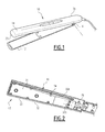
figure 1 is a perspective view of a device according to the invention; -
figure 2 is a perspective view of a shell of the device offigure 1 ; -
figure 3 is a view similar tofigure 2 with a support and a treating plate arranged in the device according to the invention; -
figure 4 is a view similar tofigure 3 with a cover plate arranged in the device according to the invention; -
figure 5 is a transverse cross-section offigure 4 ; -
figure 6 is an exploded view of another device according to the invention; -
figure 7 is a transverse cross-section of the device offigure 6 . - A
first device 10 for treating the hair according to the invention is illustrated infigure 1 . - In this example, the
device 10 for treating the hair is a straightening iron. It comprises twoarms hinge 18 connecting thearms proximal ends 16. Thearms hinge 18 between a first opened configuration for inserting hair between thearms figure 1 , and a second closed configuration for treating the hair. - As shown in
figures 2 and3 , at least one of thearms arm shell 22, asupport 24 housed in theshell 22, atreatment plate 26 supported by thesupport 24, and at least anelectrical heating element 25 inserted between thesupport 24 and thetreatment plate 26. It advantageously comprises acover plate 56, as shown infigure 4 . - The
arm first sealing element 28 sandwiched between thesupport 24 and thetreatment plate 26 and asecond sealing element 30 sandwiched between thesupport 24 and theshell 22. - As illustrated in
figure 2 , theshell 22 comprises a hollow wall, defining anouter face 32 corresponding to the external surface of thearm hollow face 34. Theshell 22 comprisesseveral sockets 36 protruding on theinner face 34 of theshell 22 to receive thesupport 24. - The
shell 22 has here a pseudo rectangular shape. In a variant, it may have an ovoid shape or another shape. - The
support 24, as shown infigure 3 , is housed in theshell 22. Thesupport 24 here comprises a firstperipheral plate 24A and a second central supportingplate 24B fixed at the center of the firstperipheral plate 24A. - The
support 24 has aninner face 38 facing theinner face 34 of theshell 22. - The first
peripheral plate 24A of thesupport 24 comprises a central opening designed to receive thetreatment plate 26, partially thefirst sealing element 28, and thesecond plate 24B. - As shown in
figure 5 , the second central supportingplate 24B is located in the central opening of the firstperipheral plate 24A. It defines anouter face 42 designed to support thetreatment plate 26. Theouter face 42 defines a housing receiving theelectrical heating element 25. - The housing is delimited by an
inner face 48 of thetreatment plate 26, by side walls extending substantially perpendicularly to thetreatment plate 26, and by theouter face 42 of the second central supportingplate 24B of thesupport 24. - The second central supporting
plate 24B is, for example, secured to the firstperipheral plate 24A by clipping or by bonding with an adhesive. - The second central supporting
plate 24B hasside tongues 43 located in the upper part of the second central supportingplate 24B. Theside tongues 43 fasten an inner flange of thetreatment plate 26 with the second central supportingplate 24B and compress thefirst sealing element 28 between the inner flange of thetreatment plate 26 and the outer surface of the second central supportingplate 24B. - The
treatment plate 26 has anouter face 50 which comes into contact with a hair lock during the hair treatment. Thetreatment plate 26 also has aninner face 48, opposite to theouter face 50, defining the upper side of the housing. - The
treatment plate 26 can be made of metal, for example aluminum, or of ceramic. - The
electrical heating element 25 is pressed against theinner face 48 of thetreatment plate 26. In the example offigure 5 , thearm spring 49 located into the housing between theelectrical heating element 25 and theouter face 42 of the second central supportingplate 24B, to press the electrical heating element against theinner face 48 of thetreatment plate 26. For example, thespring 49 is an inclined flexible blade. - The
electrical heating element 25 is for example a heating resistance. It is preferably contacting theinner face 48 of thetreatment plate 26 to ensure a temperature increase of thetreatment plate 26. - In the example of
figure 5 , anelectric insulator 27, for example a micanite cardboard taking the form of a thin leaf having electrical insulation properties and a thermal conductivity allowing heat transfer between theheating element 25 and thetreatment plate 26, is placed around or/and surrounds theelectrical heating element 25, in order to electrically protect the latter. - Advantageously, the
arm fastening elements 52 to secure thetreatment plate 26 and thesupport 24 together. Thefastening elements 52 are for example, screws or snap rings. - The
first sealing element 28 is placed at the perimeter of the housing, between thetreatment plate 26, the firstperipheral plate 24A and the second central supportingplate 24B of thesupport 24. Thefirst sealing element 28 is fitted to surround thetreatment plate 26. It is at least partially covered by thecover 56. - The
first sealing element 28 is preferably a gasket, for example made of a silicone, a rubber or a polymeric elastomer. - The
second sealing element 30 is placed in the inner volume defined between theinner face 38 of the firstperipheral plate 24A of thesupport 24 and theinner face 34 of theshell 22. - Advantageously, as shown in
figure 2 , thesecond sealing element 30 is located along the perimeter of theinner face 34 of theshell 22 at the bottom of theinner face 34. - In the embodiment shown in
figure 2 , thesecond sealing element 30 has a closed ring shape. It here comprises a "U"-shapedsealing segment 30A and atransverse sealing segment 30B, closing the "U"-shapedsealing segment 30A. In another variant, the "U"-shapedsealing segment 30A is made in one single piece of material with thetransverse sealing segment 30B. - The "U"-shaped
sealing element 30A follows the shape of the perimeter of thedistal end 20 of thearm - The
transverse sealing segment 30B is placed in contact with theinner face 42 of the firstperipheral plate 24A of thesupport 24, for closing the "U"-shapedsealing segment 30A. - Advantageously, the
transverse sealing segment 30B comprises at least a passage opening for receiving an electrical cord of theelectrical heating element 25. - Advantageously, the "U"-shaped
sealing segment 30A and thetransverse sealing segment 30B are respectively secured to theinner face 34 of theshell 22 and theinner face 42 of the firstperipheral plate 24A by bonding. - Advantageously, the
arm third sealing element 54, for example a sealing washer. - The
third sealing element 54 is here disposed between afastening element 52 and thesupport 24. In a variant, thethird sealing element 54 could also be placed between afastening element 52 and theshell 22. In another variant, the third sealing element is made in one single piece of material with the "U"-shapedsecond sealing segment 30A. - The sealing
elements - The
cover plate 56, as illustrated infigures 4 and 5 is applied above theouter face 42 of the firstperipheral plate 24A. It covers the firstperipheral plate 24A around thetreatment plate 26. It extends to a peripheral edge of theshell 22. - An example of cosmetic method carried out with the
device 10 according to the invention will be now described. - The method comprises the steps of applying water and/or cosmetic composition to the hair and then passing the
device 10 over the hair. - Initially, in the application step, the user wets a hair lock and/or applies a cosmetic product on the hair lock.
- The user subsequently activates the
device 10 to electrically power theelectric heating element 25. Thetreatment plate 26 is heated via theelectrical heating element 25, for example at a temperature comprised between 50°C and 230 °C. Preferentially, the temperature is comprised between 80°C and 180 °C. - The user then introduces a hair lock between the two
arms device 10 in the opened position and closes it manually in order to pinch the hair lock against thetreatment plate 26. - When the wet hair lock comes into contact with the
hot treatment plate 26, the water evaporates and creates steam. The cosmetic product fluidizes and streams along thedistal end 20 of thearm - The
first sealing element 28 prevents any runoff to leak inside thedevice 10 via the space between thetreatment plate 26 and thesupport 24 or thecover plate 56 disposed above thesupport 24. - When a significant runoff occurs, the
second sealing element 30 prevents liquids to leak into the inner part of thedevice 10 via a peripheral space between thesupport 24 or thecover plate 56, and/or theshell 22. - In case of liquid infiltration into the
arm second sealing element 30 avoids any runoff to penetrate into theproximal end 16 of thearm proximal end 16. - As a result, the
device 10 is completely secured from fluid infiltration both into thedistal end 20 and theproximal end 16 of thearm device 10 are protected against irreversible damages, like short circuits. - In a variant, the
first sealing element 28 is placed around thetreatment plate 26 and/or has a different shape. - In another variant, the
second sealing element 30 has another shape. For example it is "U"-shaped. - A
second device 110 for treating the hair, according to the invention is illustrated infigures 6 and 7 . - Just like the first device according to the invention, the
device 110 for treating the hair is a straightening iron. It comprises twoarms hinge 118 connecting thearms arms hinge 118 between a first opened configuration for inserting hair between thearms - At least one of the
arms arm shell 122, asupport 124 housed in theshell 122, atreatment plate 126 supported by thesupport 124, and at least anelectrical heating element 125 inserted between thesupport 124 and thetreatment plate 126. It advantageously comprises acover plate 156. - The
arm first sealing element 128 sandwiched between thesupport 124 and thetreatment plate 126 and asecond sealing element 130 sandwiched between thesupport 124 and theshell 122. - As illustrated in
figure 6 , theshell 122 comprises a hollow wall, defining anouter face 132 corresponding to the external surface of thearm hollow face 134. Theshell 122 comprisesseveral sockets 136 protruding on theinner face 134 of theshell 122 to receive thesupport 124. - The
shell 122 has here a pseudo rectangular shape. In a variant it may have ovoid-shaped or another shape. - The
support 124 is housed in theshell 122. Thesupport 124 comprises a plate having aninner face 138 facing theinner face 134 of theshell 122. - The inner faces 134, 138 delimit between them an inner volume between the
support 124 and theshell 122. Thesupport 124 further has anouter face 142, designed to support thetreatment plate 126. Theouter face 142 defines a housing receiving theelectrical heating element 125. - The housing is delimited by an
inner face 148 of thetreatment plate 126, by side walls extending substantially perpendicularly to thetreatment plate 126, and by theouter face 142 of thesupport 124. - The
treatment plate 126 has anouter face 150 which comes into contact with a hair lock during the hair treatment. Thetreatment plate 126 also has aninner face 148, opposite to theouter face 150, defining the upper side of the housing. - The
treatment plate 126 can be made of metal, for example aluminum, or of ceramic. - The
electrical heating element 125 is for example a heating resistance. It is preferably contacting theinner face 148 of thetreatment plate 126 to ensure a temperature increase of thetreatment plate 126. - In the example of
figure 7 , anelectric insulator 127, for example a micanite cardboard having electrical insulation properties and a thermal conductivity allowing heat transfer between theheating element 125 and thetreatment plate 126, is placed above theelectrical heating element 125, in order to electrically protect the latter. In another embodiment, theelectric insulator 127 can take the form of a thin leaf placed around or/and surrounding theheating element 125. - Advantageously, the
arm fastening elements 152 to secure thetreatment plate 126 and thesupport 124 together. Thefastening elements 152 are for example, screws or snap rings. - The
first sealing element 128 is placed at the perimeter of the housing, and is fitted to surround thetreatment plate 126. - The
first sealing element 128 is preferably a gasket, for example made of a silicone, a rubber or a polymeric elastomer. - The
second sealing element 130 is placed in the inner volume defined between theinner face 138 of thesupport 124 and theinner face 134 of theshell 122. - Advantageously, the
second sealing element 130 is located in an area of the inner volume, which separates theproximal end 116 and thedistal end 120 of thearm - In the embodiment shown in
figure 6 , thesecond sealing element 130 is a block. - As shown in
figure 6 , the block has a pseudo rectangular shape. It has more generally a complementary shape into theinner face 134 of theshell 122. It is placed in the inner volume in contact with thesupport 124 on its upper surface and in contact with theshell 122 on its lower and lateral surface. - The block fills at least one transverse section of the inner volume. It thus defines a proximal compartment and a distal compartment in the inner volume, which are tightly sealed one from another.
- In the example of
figure 6 , the block extends below theproximal end 116 of the housing. Its length taken along a longitudinal axis of thearm arm - Advantageously, the block comprises at least a passage opening for receiving an electrical cord of the
electrical heating element 125. - Advantageously at least one
socket 136 passes through the block. - Advantageously, the
arm third sealing element 154, for example a sealing washer. - The
third sealing element 154 is here disposed between afastening element 152 and thesupport 124. In a variant, thethird sealing element 154 could also be placed between afastening element 152 and theshell 122. - The sealing
elements - In one embodiment, the
cover plate 156, as illustrated infigure 6 is applied above theouter face 142 of thesupport 124. It covers thesupport 124 around thetreatment plate 126. It extends to a peripheral edge of theshell 122. - An example of cosmetic method carried out with the
device 110 according to the invention will be now described. - The method comprises the steps of applying water and/or cosmetic composition to the hair and passing the
device 110 over the hair. - In the application step, the user wets a hair lock and/or applies a cosmetic product on the hair lock.
- The user subsequently activates the
device 110 to electrically power theelectric heating element 125. Thetreatment plate 126 is heated via theelectrical heating element 125, for example at a temperature comprised between 50 °C and 230 °C. Preferentially, the temperature is comprised between 80°C and 180 °C. - The user then introduces a hair lock between the two
arms device 110 in the opened position and closes it manually in order to pinch the hair lock against thetreatment plate 126. - When the wet hair lock comes into contact with the
hot treatment plate 126, the water evaporates and creates steam. The cosmetic product fluidizes and streams along thedistal end 120 of thearm - The
first sealing element 128 prevents any runoff to leak inside thedevice 110 via the space between thetreatment plate 126 and thesupport 124 or thecover plate 156 disposed above thesupport 124. - In case of liquid infiltration into the
arm second sealing element 130 avoids any runoff to penetrate into theproximal end 116 of thearm proximal end 116. - As a result, the
device 110 is completely secured from fluid infiltration both into thedistal end 120 and theproximal end 116 of thearm device 110 are protected against irreversible damages, like short circuits. - In a variant, the
first sealing element 128 is placed between thesupport 124 and thetreatment plate 126 and/or has a different shape. - The zone of the device which is in contact with hair and/or water and/or formula is generally watertight and it can particularly meet the requirements of standards IPX4. Such a device can be used quite safely on hair that is very wet or covered with cosmetic product. It ensures reliability to the use and makes the treatment of hair risk-free for the user handling the device.
- The invention is not limited to a straightening iron as the device for treating the hair. The device may be any appliance for taking care of, shaping, dyeing or bleaching the hair and/or any electrical iron in which runoff is likely to occur and so which requires sealing elements with respect to this runoff.
- The expression "comprising a" is synonymous with "comprising at least one".
Claims (10)
- Device (10) for treating the hair, comprising two arms (12, 14) that are able to move relative to one another between a first opened configuration for inserting hair between the arms (12, 14) and a second closed configuration for treating the hair, at least one of the arms (12, 14) comprising :- a shell (22),- a support (24) housed in said shell (22),- a treatment plate (26) supported by the support (24),- an electrical heating element (25) received in a housing defined between the support (24) and an inner face (48) of the treatment plate (26),- a first sealing element (28) sandwiched between the support (24) and the treatment plate (26),- a second sealing element (30),characterized in that the second sealing element (30) is sandwiched between the support (24) and the shell (22).
- Device according to claim 1, characterized in that the support (24) has an outer face (42) supporting the treatment plate (26), the outer face (42) delimiting the housing receiving the at least one electrical heating element (25), the first sealing element (28) being disposed at the perimeter of the housing, the support (24) having an inner face (38) opposite to the outer face (42) and defining an inner volume with the shell (22), the second sealing element (30) being disposed in said inner volume.
- Device according to any one of the preceding claims, characterized in that each arm (12, 14) has a first sealing element (28) and a second sealing element (30).
- Device according to any one of the preceding claims, characterized in that the second sealing element (30) is located along the perimeter of an inner face (34) of the shell (22).
- Device according to any one of the preceding claims, characterized in that the second sealing element (30) has a closed ring shape.
- Device according to any one of the preceding claims, characterized in that the second sealing element (30) is a gasket.
- Device according to any one of the preceding claims, characterized in that the arm (12, 14) comprises a third sealing element (54).
- Device according to claim 7, characterized in that the third sealing element (54) is located between a fastening element (52) and the support (24) or the shell (22).
- Device according to any one of the preceding claims, characterized in that the sealing element (28, 30, 54) is made of a silicone elastomer or a rubber polymer.
- Cosmetic method for treating hair comprising the steps of :- providing a device (10) according to any one of the preceding claims,- applying water and/or a cosmetic composition to the hair,- heating the treatment plate (26) with the electrical heating element (25), and- passing the treatment plate (26) of the device (10) over the hair.
Priority Applications (8)
| Application Number | Priority Date | Filing Date | Title |
|---|---|---|---|
| ES16305566T ES2713418T3 (en) | 2016-05-13 | 2016-05-13 | Device for treating hair and related procedure |
| EP16305566.8A EP3243404B1 (en) | 2016-05-13 | 2016-05-13 | Device for treating the hair, and related method |
| PT16305566T PT3243404T (en) | 2016-05-13 | 2016-05-13 | Device for treating the hair, and related method |
| BR112018073266-4A BR112018073266B1 (en) | 2016-05-13 | 2017-05-12 | DEVICE FOR HAIR TREATMENT AND COSMETIC METHOD FOR HAIR TREATMENT |
| JP2018559747A JP6735852B2 (en) | 2016-05-13 | 2017-05-12 | Device for treating hair and related methods |
| US16/099,764 US11744342B2 (en) | 2016-05-13 | 2017-05-12 | Device for treating the hair, and related method |
| CN201780029375.2A CN109068823B (en) | 2016-05-13 | 2017-05-12 | Apparatus and related method for treating hair |
| PCT/EP2017/061461 WO2017194737A1 (en) | 2016-05-13 | 2017-05-12 | Device for treating the hair, and related method |
Applications Claiming Priority (1)
| Application Number | Priority Date | Filing Date | Title |
|---|---|---|---|
| EP16305566.8A EP3243404B1 (en) | 2016-05-13 | 2016-05-13 | Device for treating the hair, and related method |
Publications (2)
| Publication Number | Publication Date |
|---|---|
| EP3243404A1 true EP3243404A1 (en) | 2017-11-15 |
| EP3243404B1 EP3243404B1 (en) | 2018-11-28 |
Family
ID=56507540
Family Applications (1)
| Application Number | Title | Priority Date | Filing Date |
|---|---|---|---|
| EP16305566.8A Active EP3243404B1 (en) | 2016-05-13 | 2016-05-13 | Device for treating the hair, and related method |
Country Status (8)
| Country | Link |
|---|---|
| US (1) | US11744342B2 (en) |
| EP (1) | EP3243404B1 (en) |
| JP (1) | JP6735852B2 (en) |
| CN (1) | CN109068823B (en) |
| BR (1) | BR112018073266B1 (en) |
| ES (1) | ES2713418T3 (en) |
| PT (1) | PT3243404T (en) |
| WO (1) | WO2017194737A1 (en) |
Families Citing this family (2)
| Publication number | Priority date | Publication date | Assignee | Title |
|---|---|---|---|---|
| FR3075576B1 (en) * | 2017-12-22 | 2021-08-27 | Seb Sa | IMPROVED WATERPROOFING HAIR TREATMENT DEVICE |
| GB2614263A (en) * | 2021-12-22 | 2023-07-05 | Jemella Ltd | Apparatus and method for drying and styling hair |
Citations (2)
| Publication number | Priority date | Publication date | Assignee | Title |
|---|---|---|---|---|
| EP1661480A1 (en) | 2003-08-01 | 2006-05-31 | Phild Co., Ltd. | Hair iron |
| WO2015091043A2 (en) * | 2013-12-19 | 2015-06-25 | L'oreal | Device for treating the hair, comprising a seal |
Family Cites Families (22)
| Publication number | Priority date | Publication date | Assignee | Title |
|---|---|---|---|---|
| GB8610888D0 (en) | 1986-05-03 | 1986-06-11 | Int Computers Ltd | Variable delay circuit |
| JP3609064B2 (en) * | 2002-05-28 | 2005-01-12 | 服部ヒーティング工業株式会社 | Iron |
| US7178531B2 (en) * | 2002-06-26 | 2007-02-20 | The Procter & Gamble Company | Device for achieving smooth and straight hair |
| AU2002315710B8 (en) * | 2002-06-26 | 2006-08-24 | Matsushita Electric Works, Ltd. | Hair iron |
| US20080178900A1 (en) * | 2004-12-20 | 2008-07-31 | Jason Blyden | Hair iron |
| CA2508607C (en) * | 2005-05-30 | 2007-09-11 | Camco Inc. | Clothes dryer door assembly |
| FR2913317B1 (en) * | 2007-03-07 | 2011-02-11 | Seb Sa | HAIRSTYLING APPARATUS |
| CN201349663Y (en) * | 2008-11-26 | 2009-11-25 | 深圳市奋达电器有限公司 | Hair straightener |
| KR200456291Y1 (en) * | 2009-09-08 | 2011-10-26 | 주식회사 아인스엠앤엠 | A cosmetic apparatus for hair treatment |
| JP2011097999A (en) * | 2009-11-04 | 2011-05-19 | Panasonic Electric Works Co Ltd | Hair iron |
| ITMI20091946A1 (en) | 2009-11-06 | 2011-05-07 | Tenacta Group Spa | DEVICE FOR CURLING AND / OR MODELING HAIR |
| FR2967018B1 (en) * | 2010-11-05 | 2014-04-25 | Seb Sa | PERISTALTIC PUMP HAIRSTYLING APPARATUS |
| FR2974485B1 (en) * | 2011-04-29 | 2014-02-28 | Seb Sa | HAND HAIRSTONE APPARATUS WITH COSMETIC PRODUCT DELIVERY SYSTEM |
| DE102011079642A1 (en) * | 2011-07-22 | 2013-01-24 | BSH Bosch und Siemens Hausgeräte GmbH | The hair styling appliance |
| JP5903617B2 (en) * | 2011-10-03 | 2016-04-13 | パナソニックIpマネジメント株式会社 | Curling iron |
| CN202618704U (en) * | 2012-06-14 | 2012-12-26 | 浙江百特电器有限公司 | Curling device |
| FR2997271B1 (en) * | 2012-10-26 | 2016-01-01 | Oreal | DEVICE FOR TREATING THE HAIR |
| WO2015161134A1 (en) * | 2014-04-16 | 2015-10-22 | Spectrum Brands, Inc. | Heated appliance |
| FR3020930B1 (en) * | 2014-05-14 | 2016-06-24 | Seb Sa | STEAM HAIRSTAPPING APPARATUS WITH MEANS OF CONTAINING STEAM |
| US10912363B1 (en) * | 2014-09-05 | 2021-02-09 | Bruce S. Kanter | Hair treatment device for coloring hair |
| CN105077953B (en) * | 2015-08-07 | 2018-04-03 | 温州市拉博电器有限公司 | A kind of curler |
| CN205018485U (en) * | 2015-09-24 | 2016-02-10 | 朱世旺 | Novel scissors type electricity splint |
-
2016
- 2016-05-13 PT PT16305566T patent/PT3243404T/en unknown
- 2016-05-13 ES ES16305566T patent/ES2713418T3/en active Active
- 2016-05-13 EP EP16305566.8A patent/EP3243404B1/en active Active
-
2017
- 2017-05-12 WO PCT/EP2017/061461 patent/WO2017194737A1/en not_active Ceased
- 2017-05-12 BR BR112018073266-4A patent/BR112018073266B1/en active IP Right Grant
- 2017-05-12 JP JP2018559747A patent/JP6735852B2/en not_active Expired - Fee Related
- 2017-05-12 US US16/099,764 patent/US11744342B2/en active Active
- 2017-05-12 CN CN201780029375.2A patent/CN109068823B/en active Active
Patent Citations (2)
| Publication number | Priority date | Publication date | Assignee | Title |
|---|---|---|---|---|
| EP1661480A1 (en) | 2003-08-01 | 2006-05-31 | Phild Co., Ltd. | Hair iron |
| WO2015091043A2 (en) * | 2013-12-19 | 2015-06-25 | L'oreal | Device for treating the hair, comprising a seal |
Also Published As
| Publication number | Publication date |
|---|---|
| CN109068823B (en) | 2021-07-20 |
| BR112018073266B1 (en) | 2023-01-10 |
| US11744342B2 (en) | 2023-09-05 |
| PT3243404T (en) | 2019-03-19 |
| JP2019514614A (en) | 2019-06-06 |
| CN109068823A (en) | 2018-12-21 |
| WO2017194737A1 (en) | 2017-11-16 |
| EP3243404B1 (en) | 2018-11-28 |
| ES2713418T3 (en) | 2019-05-21 |
| JP6735852B2 (en) | 2020-08-05 |
| US20190116952A1 (en) | 2019-04-25 |
| BR112018073266A2 (en) | 2019-02-19 |
Similar Documents
| Publication | Publication Date | Title |
|---|---|---|
| US10925368B2 (en) | Device for treating the hair, comprising a seal | |
| US12313294B2 (en) | PTC heater | |
| EP3243404B1 (en) | Device for treating the hair, and related method | |
| JP6240668B2 (en) | Electric heaters that make hot water and / or steam | |
| CA2949611A1 (en) | Lunchbox | |
| US5118927A (en) | Precooked food warmer utilizing immersible sword like heat transfer members | |
| JP4412283B2 (en) | hair iron | |
| RU2017133670A (en) | COSMETIC DEVICE | |
| JPS61259700A (en) | Method and apparatus for closing evaporation chamber of steam iron | |
| US20120177429A1 (en) | Applicator device for fusible products | |
| KR101846945B1 (en) | Hair iron with waterproof | |
| JPH0436745Y2 (en) | ||
| KR100340454B1 (en) | Cooker | |
| KR100746445B1 (en) | Electric pressure cooker | |
| US1282476A (en) | Electric fluid-heater. | |
| RU2329342C2 (en) | Steam iron with plastic skirt incorporating evaporation chamber | |
| KR20150122974A (en) | hair iron | |
| RU2814134C2 (en) | Device for hair treatment with increased tightness and efficiency | |
| ES2741350T3 (en) | Temperature dependent switch with insulating washer | |
| KR200430656Y1 (en) | Electric pressure thermal cooker | |
| US20160201681A1 (en) | Electric pump | |
| KR0130300Y1 (en) | Electric rice cooker | |
| US1946847A (en) | Hair waving apparatus | |
| JPH0355394Y2 (en) | ||
| US1692875A (en) | Protective housing for electrical devices |
Legal Events
| Date | Code | Title | Description |
|---|---|---|---|
| PUAI | Public reference made under article 153(3) epc to a published international application that has entered the european phase |
Free format text: ORIGINAL CODE: 0009012 |
|
| STAA | Information on the status of an ep patent application or granted ep patent |
Free format text: STATUS: THE APPLICATION HAS BEEN PUBLISHED |
|
| AK | Designated contracting states |
Kind code of ref document: A1 Designated state(s): AL AT BE BG CH CY CZ DE DK EE ES FI FR GB GR HR HU IE IS IT LI LT LU LV MC MK MT NL NO PL PT RO RS SE SI SK SM TR |
|
| AX | Request for extension of the european patent |
Extension state: BA ME |
|
| STAA | Information on the status of an ep patent application or granted ep patent |
Free format text: STATUS: REQUEST FOR EXAMINATION WAS MADE |
|
| 17P | Request for examination filed |
Effective date: 20180330 |
|
| RBV | Designated contracting states (corrected) |
Designated state(s): AL AT BE BG CH CY CZ DE DK EE ES FI FR GB GR HR HU IE IS IT LI LT LU LV MC MK MT NL NO PL PT RO RS SE SI SK SM TR |
|
| INTG | Intention to grant announced |
Effective date: 20180611 |
|
| GRAP | Despatch of communication of intention to grant a patent |
Free format text: ORIGINAL CODE: EPIDOSNIGR1 |
|
| STAA | Information on the status of an ep patent application or granted ep patent |
Free format text: STATUS: GRANT OF PATENT IS INTENDED |
|
| GRAS | Grant fee paid |
Free format text: ORIGINAL CODE: EPIDOSNIGR3 |
|
| GRAA | (expected) grant |
Free format text: ORIGINAL CODE: 0009210 |
|
| STAA | Information on the status of an ep patent application or granted ep patent |
Free format text: STATUS: THE PATENT HAS BEEN GRANTED |
|
| AK | Designated contracting states |
Kind code of ref document: B1 Designated state(s): AL AT BE BG CH CY CZ DE DK EE ES FI FR GB GR HR HU IE IS IT LI LT LU LV MC MK MT NL NO PL PT RO RS SE SI SK SM TR |
|
| REG | Reference to a national code |
Ref country code: CH Ref legal event code: EP |
|
| REG | Reference to a national code |
Ref country code: AT Ref legal event code: REF Ref document number: 1069205 Country of ref document: AT Kind code of ref document: T Effective date: 20181215 |
|
| REG | Reference to a national code |
Ref country code: DE Ref legal event code: R096 Ref document number: 602016007586 Country of ref document: DE |
|
| REG | Reference to a national code |
Ref country code: IE Ref legal event code: FG4D |
|
| REG | Reference to a national code |
Ref country code: PT Ref legal event code: SC4A Ref document number: 3243404 Country of ref document: PT Date of ref document: 20190319 Kind code of ref document: T Free format text: AVAILABILITY OF NATIONAL TRANSLATION Effective date: 20190228 |
|
| REG | Reference to a national code |
Ref country code: NL Ref legal event code: FP |
|
| REG | Reference to a national code |
Ref country code: LT Ref legal event code: MG4D |
|
| REG | Reference to a national code |
Ref country code: AT Ref legal event code: MK05 Ref document number: 1069205 Country of ref document: AT Kind code of ref document: T Effective date: 20181128 |
|
| PG25 | Lapsed in a contracting state [announced via postgrant information from national office to epo] |
Ref country code: FI Free format text: LAPSE BECAUSE OF FAILURE TO SUBMIT A TRANSLATION OF THE DESCRIPTION OR TO PAY THE FEE WITHIN THE PRESCRIBED TIME-LIMIT Effective date: 20181128 Ref country code: IS Free format text: LAPSE BECAUSE OF FAILURE TO SUBMIT A TRANSLATION OF THE DESCRIPTION OR TO PAY THE FEE WITHIN THE PRESCRIBED TIME-LIMIT Effective date: 20190328 Ref country code: NO Free format text: LAPSE BECAUSE OF FAILURE TO SUBMIT A TRANSLATION OF THE DESCRIPTION OR TO PAY THE FEE WITHIN THE PRESCRIBED TIME-LIMIT Effective date: 20190228 Ref country code: AT Free format text: LAPSE BECAUSE OF FAILURE TO SUBMIT A TRANSLATION OF THE DESCRIPTION OR TO PAY THE FEE WITHIN THE PRESCRIBED TIME-LIMIT Effective date: 20181128 Ref country code: HR Free format text: LAPSE BECAUSE OF FAILURE TO SUBMIT A TRANSLATION OF THE DESCRIPTION OR TO PAY THE FEE WITHIN THE PRESCRIBED TIME-LIMIT Effective date: 20181128 Ref country code: LT Free format text: LAPSE BECAUSE OF FAILURE TO SUBMIT A TRANSLATION OF THE DESCRIPTION OR TO PAY THE FEE WITHIN THE PRESCRIBED TIME-LIMIT Effective date: 20181128 Ref country code: BG Free format text: LAPSE BECAUSE OF FAILURE TO SUBMIT A TRANSLATION OF THE DESCRIPTION OR TO PAY THE FEE WITHIN THE PRESCRIBED TIME-LIMIT Effective date: 20190228 Ref country code: LV Free format text: LAPSE BECAUSE OF FAILURE TO SUBMIT A TRANSLATION OF THE DESCRIPTION OR TO PAY THE FEE WITHIN THE PRESCRIBED TIME-LIMIT Effective date: 20181128 |
|
| REG | Reference to a national code |
Ref country code: ES Ref legal event code: FG2A Ref document number: 2713418 Country of ref document: ES Kind code of ref document: T3 Effective date: 20190521 |
|
| PG25 | Lapsed in a contracting state [announced via postgrant information from national office to epo] |
Ref country code: AL Free format text: LAPSE BECAUSE OF FAILURE TO SUBMIT A TRANSLATION OF THE DESCRIPTION OR TO PAY THE FEE WITHIN THE PRESCRIBED TIME-LIMIT Effective date: 20181128 Ref country code: SE Free format text: LAPSE BECAUSE OF FAILURE TO SUBMIT A TRANSLATION OF THE DESCRIPTION OR TO PAY THE FEE WITHIN THE PRESCRIBED TIME-LIMIT Effective date: 20181128 Ref country code: RS Free format text: LAPSE BECAUSE OF FAILURE TO SUBMIT A TRANSLATION OF THE DESCRIPTION OR TO PAY THE FEE WITHIN THE PRESCRIBED TIME-LIMIT Effective date: 20181128 |
|
| REG | Reference to a national code |
Ref country code: GR Ref legal event code: EP Ref document number: 20190400623 Country of ref document: GR Effective date: 20190509 |
|
| PG25 | Lapsed in a contracting state [announced via postgrant information from national office to epo] |
Ref country code: CZ Free format text: LAPSE BECAUSE OF FAILURE TO SUBMIT A TRANSLATION OF THE DESCRIPTION OR TO PAY THE FEE WITHIN THE PRESCRIBED TIME-LIMIT Effective date: 20181128 Ref country code: PL Free format text: LAPSE BECAUSE OF FAILURE TO SUBMIT A TRANSLATION OF THE DESCRIPTION OR TO PAY THE FEE WITHIN THE PRESCRIBED TIME-LIMIT Effective date: 20181128 Ref country code: DK Free format text: LAPSE BECAUSE OF FAILURE TO SUBMIT A TRANSLATION OF THE DESCRIPTION OR TO PAY THE FEE WITHIN THE PRESCRIBED TIME-LIMIT Effective date: 20181128 |
|
| REG | Reference to a national code |
Ref country code: DE Ref legal event code: R097 Ref document number: 602016007586 Country of ref document: DE |
|
| PG25 | Lapsed in a contracting state [announced via postgrant information from national office to epo] |
Ref country code: EE Free format text: LAPSE BECAUSE OF FAILURE TO SUBMIT A TRANSLATION OF THE DESCRIPTION OR TO PAY THE FEE WITHIN THE PRESCRIBED TIME-LIMIT Effective date: 20181128 Ref country code: SM Free format text: LAPSE BECAUSE OF FAILURE TO SUBMIT A TRANSLATION OF THE DESCRIPTION OR TO PAY THE FEE WITHIN THE PRESCRIBED TIME-LIMIT Effective date: 20181128 Ref country code: RO Free format text: LAPSE BECAUSE OF FAILURE TO SUBMIT A TRANSLATION OF THE DESCRIPTION OR TO PAY THE FEE WITHIN THE PRESCRIBED TIME-LIMIT Effective date: 20181128 Ref country code: SK Free format text: LAPSE BECAUSE OF FAILURE TO SUBMIT A TRANSLATION OF THE DESCRIPTION OR TO PAY THE FEE WITHIN THE PRESCRIBED TIME-LIMIT Effective date: 20181128 |
|
| PLBE | No opposition filed within time limit |
Free format text: ORIGINAL CODE: 0009261 |
|
| STAA | Information on the status of an ep patent application or granted ep patent |
Free format text: STATUS: NO OPPOSITION FILED WITHIN TIME LIMIT |
|
| PG25 | Lapsed in a contracting state [announced via postgrant information from national office to epo] |
Ref country code: SI Free format text: LAPSE BECAUSE OF FAILURE TO SUBMIT A TRANSLATION OF THE DESCRIPTION OR TO PAY THE FEE WITHIN THE PRESCRIBED TIME-LIMIT Effective date: 20181128 |
|
| 26N | No opposition filed |
Effective date: 20190829 |
|
| REG | Reference to a national code |
Ref country code: CH Ref legal event code: PL |
|
| PG25 | Lapsed in a contracting state [announced via postgrant information from national office to epo] |
Ref country code: CH Free format text: LAPSE BECAUSE OF NON-PAYMENT OF DUE FEES Effective date: 20190531 Ref country code: LI Free format text: LAPSE BECAUSE OF NON-PAYMENT OF DUE FEES Effective date: 20190531 Ref country code: MC Free format text: LAPSE BECAUSE OF FAILURE TO SUBMIT A TRANSLATION OF THE DESCRIPTION OR TO PAY THE FEE WITHIN THE PRESCRIBED TIME-LIMIT Effective date: 20181128 |
|
| PG25 | Lapsed in a contracting state [announced via postgrant information from national office to epo] |
Ref country code: TR Free format text: LAPSE BECAUSE OF FAILURE TO SUBMIT A TRANSLATION OF THE DESCRIPTION OR TO PAY THE FEE WITHIN THE PRESCRIBED TIME-LIMIT Effective date: 20181128 |
|
| PG25 | Lapsed in a contracting state [announced via postgrant information from national office to epo] |
Ref country code: IE Free format text: LAPSE BECAUSE OF NON-PAYMENT OF DUE FEES Effective date: 20190513 |
|
| PG25 | Lapsed in a contracting state [announced via postgrant information from national office to epo] |
Ref country code: CY Free format text: LAPSE BECAUSE OF FAILURE TO SUBMIT A TRANSLATION OF THE DESCRIPTION OR TO PAY THE FEE WITHIN THE PRESCRIBED TIME-LIMIT Effective date: 20181128 |
|
| PG25 | Lapsed in a contracting state [announced via postgrant information from national office to epo] |
Ref country code: MT Free format text: LAPSE BECAUSE OF FAILURE TO SUBMIT A TRANSLATION OF THE DESCRIPTION OR TO PAY THE FEE WITHIN THE PRESCRIBED TIME-LIMIT Effective date: 20181128 Ref country code: HU Free format text: LAPSE BECAUSE OF FAILURE TO SUBMIT A TRANSLATION OF THE DESCRIPTION OR TO PAY THE FEE WITHIN THE PRESCRIBED TIME-LIMIT; INVALID AB INITIO Effective date: 20160513 |
|
| PG25 | Lapsed in a contracting state [announced via postgrant information from national office to epo] |
Ref country code: MK Free format text: LAPSE BECAUSE OF FAILURE TO SUBMIT A TRANSLATION OF THE DESCRIPTION OR TO PAY THE FEE WITHIN THE PRESCRIBED TIME-LIMIT Effective date: 20181128 |
|
| PGFP | Annual fee paid to national office [announced via postgrant information from national office to epo] |
Ref country code: NL Payment date: 20250317 Year of fee payment: 10 |
|
| PGFP | Annual fee paid to national office [announced via postgrant information from national office to epo] |
Ref country code: FR Payment date: 20250310 Year of fee payment: 10 |
|
| PGFP | Annual fee paid to national office [announced via postgrant information from national office to epo] |
Ref country code: GB Payment date: 20250320 Year of fee payment: 10 |
|
| PGFP | Annual fee paid to national office [announced via postgrant information from national office to epo] |
Ref country code: LU Payment date: 20250429 Year of fee payment: 10 |
|
| PGFP | Annual fee paid to national office [announced via postgrant information from national office to epo] |
Ref country code: DE Payment date: 20250319 Year of fee payment: 10 |
|
| PGFP | Annual fee paid to national office [announced via postgrant information from national office to epo] |
Ref country code: ES Payment date: 20250605 Year of fee payment: 10 |
|
| PGFP | Annual fee paid to national office [announced via postgrant information from national office to epo] |
Ref country code: BE Payment date: 20250410 Year of fee payment: 10 Ref country code: IT Payment date: 20250422 Year of fee payment: 10 |
|
| PGFP | Annual fee paid to national office [announced via postgrant information from national office to epo] |
Ref country code: PT Payment date: 20250508 Year of fee payment: 10 |
|
| PGFP | Annual fee paid to national office [announced via postgrant information from national office to epo] |
Ref country code: GR Payment date: 20250416 Year of fee payment: 10 |