EP3242380A1 - Motor and clutch actuator including same - Google Patents
Motor and clutch actuator including same Download PDFInfo
- Publication number
- EP3242380A1 EP3242380A1 EP15875473.9A EP15875473A EP3242380A1 EP 3242380 A1 EP3242380 A1 EP 3242380A1 EP 15875473 A EP15875473 A EP 15875473A EP 3242380 A1 EP3242380 A1 EP 3242380A1
- Authority
- EP
- European Patent Office
- Prior art keywords
- housing
- motor
- sensor
- mounting part
- control part
- Prior art date
- Legal status (The legal status is an assumption and is not a legal conclusion. Google has not performed a legal analysis and makes no representation as to the accuracy of the status listed.)
- Granted
Links
Images





Classifications
-
- H—ELECTRICITY
- H02—GENERATION; CONVERSION OR DISTRIBUTION OF ELECTRIC POWER
- H02K—DYNAMO-ELECTRIC MACHINES
- H02K7/00—Arrangements for handling mechanical energy structurally associated with dynamo-electric machines, e.g. structural association with mechanical driving motors or auxiliary dynamo-electric machines
- H02K7/14—Structural association with mechanical loads, e.g. with hand-held machine tools or fans
-
- F—MECHANICAL ENGINEERING; LIGHTING; HEATING; WEAPONS; BLASTING
- F16—ENGINEERING ELEMENTS AND UNITS; GENERAL MEASURES FOR PRODUCING AND MAINTAINING EFFECTIVE FUNCTIONING OF MACHINES OR INSTALLATIONS; THERMAL INSULATION IN GENERAL
- F16D—COUPLINGS FOR TRANSMITTING ROTATION; CLUTCHES; BRAKES
- F16D25/00—Fluid-actuated clutches
- F16D25/08—Fluid-actuated clutches with fluid-actuated member not rotating with a clutching member
-
- F—MECHANICAL ENGINEERING; LIGHTING; HEATING; WEAPONS; BLASTING
- F16—ENGINEERING ELEMENTS AND UNITS; GENERAL MEASURES FOR PRODUCING AND MAINTAINING EFFECTIVE FUNCTIONING OF MACHINES OR INSTALLATIONS; THERMAL INSULATION IN GENERAL
- F16D—COUPLINGS FOR TRANSMITTING ROTATION; CLUTCHES; BRAKES
- F16D25/00—Fluid-actuated clutches
- F16D25/08—Fluid-actuated clutches with fluid-actuated member not rotating with a clutching member
- F16D25/082—Fluid-actuated clutches with fluid-actuated member not rotating with a clutching member the line of action of the fluid-actuated members co-inciding with the axis of rotation
-
- F—MECHANICAL ENGINEERING; LIGHTING; HEATING; WEAPONS; BLASTING
- F16—ENGINEERING ELEMENTS AND UNITS; GENERAL MEASURES FOR PRODUCING AND MAINTAINING EFFECTIVE FUNCTIONING OF MACHINES OR INSTALLATIONS; THERMAL INSULATION IN GENERAL
- F16D—COUPLINGS FOR TRANSMITTING ROTATION; CLUTCHES; BRAKES
- F16D25/00—Fluid-actuated clutches
- F16D25/12—Details not specific to one of the before-mentioned types
-
- F—MECHANICAL ENGINEERING; LIGHTING; HEATING; WEAPONS; BLASTING
- F16—ENGINEERING ELEMENTS AND UNITS; GENERAL MEASURES FOR PRODUCING AND MAINTAINING EFFECTIVE FUNCTIONING OF MACHINES OR INSTALLATIONS; THERMAL INSULATION IN GENERAL
- F16D—COUPLINGS FOR TRANSMITTING ROTATION; CLUTCHES; BRAKES
- F16D29/00—Clutches and systems of clutches involving both fluid and magnetic actuation
- F16D29/005—Clutches and systems of clutches involving both fluid and magnetic actuation with a fluid pressure piston driven by an electric motor
-
- G—PHYSICS
- G01—MEASURING; TESTING
- G01D—MEASURING NOT SPECIALLY ADAPTED FOR A SPECIFIC VARIABLE; ARRANGEMENTS FOR MEASURING TWO OR MORE VARIABLES NOT COVERED IN A SINGLE OTHER SUBCLASS; TARIFF METERING APPARATUS; MEASURING OR TESTING NOT OTHERWISE PROVIDED FOR
- G01D11/00—Component parts of measuring arrangements not specially adapted for a specific variable
- G01D11/24—Housings ; Casings for instruments
- G01D11/245—Housings for sensors
-
- G—PHYSICS
- G01—MEASURING; TESTING
- G01D—MEASURING NOT SPECIALLY ADAPTED FOR A SPECIFIC VARIABLE; ARRANGEMENTS FOR MEASURING TWO OR MORE VARIABLES NOT COVERED IN A SINGLE OTHER SUBCLASS; TARIFF METERING APPARATUS; MEASURING OR TESTING NOT OTHERWISE PROVIDED FOR
- G01D5/00—Mechanical means for transferring the output of a sensing member; Means for converting the output of a sensing member to another variable where the form or nature of the sensing member does not constrain the means for converting; Transducers not specially adapted for a specific variable
- G01D5/12—Mechanical means for transferring the output of a sensing member; Means for converting the output of a sensing member to another variable where the form or nature of the sensing member does not constrain the means for converting; Transducers not specially adapted for a specific variable using electric or magnetic means
- G01D5/14—Mechanical means for transferring the output of a sensing member; Means for converting the output of a sensing member to another variable where the form or nature of the sensing member does not constrain the means for converting; Transducers not specially adapted for a specific variable using electric or magnetic means influencing the magnitude of a current or voltage
- G01D5/142—Mechanical means for transferring the output of a sensing member; Means for converting the output of a sensing member to another variable where the form or nature of the sensing member does not constrain the means for converting; Transducers not specially adapted for a specific variable using electric or magnetic means influencing the magnitude of a current or voltage using Hall-effect devices
- G01D5/145—Mechanical means for transferring the output of a sensing member; Means for converting the output of a sensing member to another variable where the form or nature of the sensing member does not constrain the means for converting; Transducers not specially adapted for a specific variable using electric or magnetic means influencing the magnitude of a current or voltage using Hall-effect devices influenced by the relative movement between the Hall device and magnetic fields
-
- H—ELECTRICITY
- H02—GENERATION; CONVERSION OR DISTRIBUTION OF ELECTRIC POWER
- H02K—DYNAMO-ELECTRIC MACHINES
- H02K11/00—Structural association of dynamo-electric machines with electric components or with devices for shielding, monitoring or protection
- H02K11/20—Structural association of dynamo-electric machines with electric components or with devices for shielding, monitoring or protection for measuring, monitoring, testing, protecting or switching
-
- H—ELECTRICITY
- H02—GENERATION; CONVERSION OR DISTRIBUTION OF ELECTRIC POWER
- H02K—DYNAMO-ELECTRIC MACHINES
- H02K11/00—Structural association of dynamo-electric machines with electric components or with devices for shielding, monitoring or protection
- H02K11/20—Structural association of dynamo-electric machines with electric components or with devices for shielding, monitoring or protection for measuring, monitoring, testing, protecting or switching
- H02K11/21—Devices for sensing speed or position, or actuated thereby
- H02K11/215—Magnetic effect devices, e.g. Hall-effect or magneto-resistive elements
-
- H—ELECTRICITY
- H02—GENERATION; CONVERSION OR DISTRIBUTION OF ELECTRIC POWER
- H02K—DYNAMO-ELECTRIC MACHINES
- H02K11/00—Structural association of dynamo-electric machines with electric components or with devices for shielding, monitoring or protection
- H02K11/30—Structural association with control circuits or drive circuits
-
- H—ELECTRICITY
- H02—GENERATION; CONVERSION OR DISTRIBUTION OF ELECTRIC POWER
- H02K—DYNAMO-ELECTRIC MACHINES
- H02K11/00—Structural association of dynamo-electric machines with electric components or with devices for shielding, monitoring or protection
- H02K11/30—Structural association with control circuits or drive circuits
- H02K11/33—Drive circuits, e.g. power electronics
-
- H—ELECTRICITY
- H02—GENERATION; CONVERSION OR DISTRIBUTION OF ELECTRIC POWER
- H02K—DYNAMO-ELECTRIC MACHINES
- H02K11/00—Structural association of dynamo-electric machines with electric components or with devices for shielding, monitoring or protection
- H02K11/30—Structural association with control circuits or drive circuits
- H02K11/38—Control circuits or drive circuits associated with geared commutator motors of the worm-and-wheel type
-
- H—ELECTRICITY
- H02—GENERATION; CONVERSION OR DISTRIBUTION OF ELECTRIC POWER
- H02K—DYNAMO-ELECTRIC MACHINES
- H02K17/00—Asynchronous induction motors; Asynchronous induction generators
- H02K17/02—Asynchronous induction motors
- H02K17/32—Structural association of asynchronous induction motors with auxiliary mechanical devices, e.g. with clutches or brakes
-
- H—ELECTRICITY
- H02—GENERATION; CONVERSION OR DISTRIBUTION OF ELECTRIC POWER
- H02K—DYNAMO-ELECTRIC MACHINES
- H02K5/00—Casings; Enclosures; Supports
- H02K5/04—Casings or enclosures characterised by the shape, form or construction thereof
- H02K5/22—Auxiliary parts of casings not covered by groups H02K5/06-H02K5/20, e.g. shaped to form connection boxes or terminal boxes
-
- H—ELECTRICITY
- H02—GENERATION; CONVERSION OR DISTRIBUTION OF ELECTRIC POWER
- H02K—DYNAMO-ELECTRIC MACHINES
- H02K7/00—Arrangements for handling mechanical energy structurally associated with dynamo-electric machines, e.g. structural association with mechanical driving motors or auxiliary dynamo-electric machines
- H02K7/10—Structural association with clutches, brakes, gears, pulleys or mechanical starters
- H02K7/108—Structural association with clutches, brakes, gears, pulleys or mechanical starters with friction clutches
-
- H—ELECTRICITY
- H02—GENERATION; CONVERSION OR DISTRIBUTION OF ELECTRIC POWER
- H02K—DYNAMO-ELECTRIC MACHINES
- H02K7/00—Arrangements for handling mechanical energy structurally associated with dynamo-electric machines, e.g. structural association with mechanical driving motors or auxiliary dynamo-electric machines
- H02K7/10—Structural association with clutches, brakes, gears, pulleys or mechanical starters
- H02K7/11—Structural association with clutches, brakes, gears, pulleys or mechanical starters with dynamo-electric clutches
-
- H—ELECTRICITY
- H02—GENERATION; CONVERSION OR DISTRIBUTION OF ELECTRIC POWER
- H02K—DYNAMO-ELECTRIC MACHINES
- H02K7/00—Arrangements for handling mechanical energy structurally associated with dynamo-electric machines, e.g. structural association with mechanical driving motors or auxiliary dynamo-electric machines
- H02K7/10—Structural association with clutches, brakes, gears, pulleys or mechanical starters
- H02K7/116—Structural association with clutches, brakes, gears, pulleys or mechanical starters with gears
-
- F—MECHANICAL ENGINEERING; LIGHTING; HEATING; WEAPONS; BLASTING
- F16—ENGINEERING ELEMENTS AND UNITS; GENERAL MEASURES FOR PRODUCING AND MAINTAINING EFFECTIVE FUNCTIONING OF MACHINES OR INSTALLATIONS; THERMAL INSULATION IN GENERAL
- F16D—COUPLINGS FOR TRANSMITTING ROTATION; CLUTCHES; BRAKES
- F16D25/00—Fluid-actuated clutches
- F16D25/08—Fluid-actuated clutches with fluid-actuated member not rotating with a clutching member
- F16D2025/081—Hydraulic devices that initiate movement of pistons in secondary cylinders for actuating clutches, i.e. primary cylinders
-
- H—ELECTRICITY
- H02—GENERATION; CONVERSION OR DISTRIBUTION OF ELECTRIC POWER
- H02K—DYNAMO-ELECTRIC MACHINES
- H02K7/00—Arrangements for handling mechanical energy structurally associated with dynamo-electric machines, e.g. structural association with mechanical driving motors or auxiliary dynamo-electric machines
- H02K7/06—Means for converting reciprocating motion into rotary motion or vice versa
Definitions
- the present invention relates to a motor, and more particularly, to a motor including a sensor connecting part configured to measure a state of an actuator, and a clutch actuator including the motor.
- a rotary shaft of a motor is connected to an actuator to transmit a driving force thereto.
- the motor and the actuator can be integrally manufactured according to characteristics of the actuator.
- a driving shaft of the actuator and a rotary shaft of the motor can be integrally formed by forming the motor and the actuator together in one housing or using a tube-type rotor.
- a control module configured to control the motor according to a state of the actuator can be provided.
- the motor having such a structure has a problem in that a size of the motor is increased due to the tube-type rotor.
- sensors configured to measure the state of the actuator are connected to the control module, but an operation of connecting the sensors to the control module is difficult and a connecting structure thereof is complex, and thus there is a problem in that reliability of sensed information is reduced.
- the driving shaft of the actuator and the rotary shaft of the motor are integrally formed, there are problems in that precise position control is difficult, and compatibility of component replacement is reduced.
- a large-sized bearing is installed at a side of the motor to overcome a load acting on the actuator, there is a problem in that the size of the motor is increased.
- the present invention is directed to providing a motor in which a driving shaft of an actuator and a rotary shaft of the motor are separately formed, a size thereof may be decreased, and sensors may be easily connected to a control module, and a clutch actuator including the motor.
- a motor including a housing, a control part coupled to the housing, a stator assembly coupled to an inside of the housing and connected to the control part, a rotor disposed inside the stator, a rotary shaft coupled to the rotor, and a sensor connecting part including a body mounted on the housing and having a sensor mounting part, and a terminal included in the body and connected to the sensor mounting part and the control part, wherein the sensor mounting part is disposed outside the housing.
- the sensor mounting part may be disposed in front of the housing to which another component is connected.
- the control part may be disposed at a rear of the housing.
- the body may be directly connected to the control part so that the terminal is electrically connected to the control part.
- the sensor mounting part may include a first mounting part disposed to face a center of a shaft of the rotary shaft and a second mounting part disposed on a front end of the body.
- the motor may further include a displacement sensor mounted on the first mounting part, and a pressure sensor mounted on the second mounting part.
- the second mounting part may include a coupling slot in which an inlet is formed to face forward.
- the housing may include a mounting slot to which a body of the sensor connecting block is detachably coupled.
- the body may include a first body having the sensor mounting part and a second body inserted into the mounting slot and coupled to the control part.
- the first body and the second body may be coupled to be stepped.
- a connecting fin connected to the terminal and coupled to the control part may be formed on an end of the second body.
- the second body may be disposed between the stator assembly and an inner surface of the housing.
- the control part may be coupled to a rear surface of the housing.
- a power terminal of the stator may be directly connected to the control part.
- the rotor may be integrally molded with and is coupled to the first sensor magnet.
- a second sensor magnet may be coupled to a rear end of the rotary shaft, and the control part may include a hall sensor disposed to face the second sensor magnet.
- a power terminal, a neutral terminal connected to the power terminal and a coil, and a bearing may be integrally molded to form the stator assembly.
- a clutch actuator including a motor having a housing, a control part coupled to the housing, a stator assembly coupled to an inside of the housing and connected to the control part, a rotor disposed inside the stator, a rotary shaft coupled to the rotor, a body mounted on the housing and having a sensor mounting part, and a terminal included in the body and connected to the sensor mounting part and the control part, wherein the sensor mounting part is disposed outside the housing, a cover including a cylinder having an inlet and an outlet, and a piston connected to the rotary shaft to reciprocate in the cylinder.
- the sensor mounting part may include a first mounting part disposed to face a center of a shaft of the rotary shaft, and a second mounting part disposed on a front end of the body.
- the piston may include a displacement sensor magnet and a displacement sensor mounted on the first mounting part.
- the front end of the body may communicate with the outlet and include a pressure sensor mounted on the second mounting part.
- the clutch actuator may further include a lead screw configured to connect the piston and the rotary shaft.
- the cover may include a bearing configured to support the lead screw.
- the present invention since mounted sensors are disposed outside a housing and a sensor connecting block mounted on the housing and directly connected to a control part is provided, a configuration and an operation of connecting the sensors to the control module are simplified, and thus there are advantageous effects in that efficiency of an assembly operation is increased and reliability of sensing information is improved.
- a rotary shaft of a motor and a driving shaft of an actuator are separately provided and the rotary shaft of the motor is provided as a solid body, there is an advantageous effect in that a size of the motor can be decreased.
- a rear surface of a housing is formed as a control part so that the housing and the control part are integrally formed, there are advantageous effects in that an assembly structure thereof can be simplified and a size of a motor can be decreased.
- a size of a bearing installed at a motor is relatively decreased, and thus there is an advantageous effect in that a size of the motor is decreased.
- a sensor connecting block is detachably coupled to a housing to be directly connected to a control part, there is an advantageous effect in that an assembly thereof is facilitated.
- FIG. 1 is a view illustrating a clutch actuator according to one exemplary embodiment of the present invention.
- FIG. 1 is a view clearly illustrating main features for a clear conceptual understanding of the present invention, and thus various modifications are expected and the scope of the present invention is not limited to specific shapes illustrated in the drawing.
- the clutch actuator may include a motor 10, a cover 20, a piston 30, and a lead screw 40.
- the motor 10 When the motor 10 is driven, the lead screw 40 rotates and the piston 30 linearly moves as the lead screw 40 rotates.
- An accommodation space S for a fluid is provided inside the cover 20, and the piston 30 is located in the accommodation space S.
- an inlet 21 and an outlet 22 in communication with the accommodation space S may be formed in the cover 20.
- a working fluid is supplied to the accommodation space S through the inlet 21, and the working fluid is discharged from the accommodation space S through the outlet 22.
- a working fluid pushed by the piston 30 and discharged through the outlet 22 may operate a clutch mounted on a vehicle.
- a displacement sensor magnet 50 may be installed at the lead screw 40.
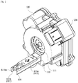
- FIG. 2 is a view illustrating a motor illustrated in FIG. 1
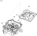
- FIG. 3 is an exploded view of the motor illustrated in FIG. 2
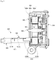
- FIG. 4 is a side cross-sectional view of the motor illustrated in FIG. 2 .
- FIGS. 2 to 4 are views clearly illustrating main features for a clear conceptual understanding of the present invention, and thus various modifications are expected and the scope of the present invention is not limited to specific shapes illustrated in the drawings.
- the motor 10 may include a housing 100, a control part 200, a stator assembly 300, a rotor 400, a rotary shaft 500, and a sensor connecting part 600.
- the housing 100 is formed in a cylindrical shape so that a space in which the stator assembly 300, the rotor 400, and the like may be installed is provided therein.
- the housing 100 is formed to be coupled to the cover 20.
- a shape or material of the housing 100 may be variously changed, a metal material capable of easily withstanding a high temperature may be selected for the housing 100 because the housing 100 is installed in a vehicle.
- one portion of the housing 100 that is, a front surface of the housing 100 connected to an actuator, may be made of aluminum.
- the entire housing 100 may be made of aluminum.
- the actuator may be coupled to a side of the front surface of the housing 100, and the control part 200 may be coupled to a side of a rear surface of the housing 100.
- a mounting slot 110 into which the sensor connecting part 600 is detachably inserted may be formed in the front surface of the housing 100.
- a center hole 111 forming a space in which the rotary shaft 500 is located and the lead screw 40 is connected to the rotary shaft 500 may be provide at the center of the housing 100, and the mounting slot 110 may be formed under the center hole 111.
- the control part 200 controls driving of the motor 10 on the basis of a state of the actuator transmitted from the sensor connecting part 600 and an external driving signal.
- a control part 200 may be integrally formed with the housing by being disposed at a rear of the housing 100 as a rear cover of the housing 100.
- FIG. 5 is a view illustrating a control part disposed on a rear surface of a housing.
- a housing terminal 120 may be provided on the rear surface of the housing 100.
- the housing terminal 120 may be disposed on a corner portion of the housing 100.
- the housing terminal 120 may be electrically connected to an external power source.
- a terminal insertion part 210 corresponding to such a housing terminal 120 may be formed on a corner portion of the control part 200.
- the control part 200 may be coupled to the rear surface of the housing 100 so that the housing terminal 120 is inserted into the terminal insertion part 210.
- the stator assembly 300 may include a stator core 300a (see FIG. 4 ), and a coil 300b (see FIG. 4 ) configured to form a rotating magnetic field may be wound around the stator core 300a.
- the coil 300b wound around the stator core 300a may be insulated by being surrounded by an insulator 300c (see FIG. 4 ).
- FIG. 6 is a view illustrating a stator assembly.
- the stator assembly 300 may be implemented to include a bus bar and a bearing therein.
- the stator assembly 300 may be formed by the stator core 300a (see FIG. 4 ), the coil 300b, and the insulator 300c being integrally molded together so that a power terminal 310 and a connecting terminal of a neutral terminal 320 are exposed to the outside.
- the stator assembly 300 may be formed by a bearing B2 being also integrally molded therewith together in a center thereof.
- a connecting terminal of one side of the power terminal 310 is extended in a radial direction to be fused and connected to the neutral terminal 320.
- a connecting terminal of the other side of the power terminal 310 may be formed to protrude upward to be directly connected to the control part 200.
- FIG. 7 is a view illustrating a stator assembly that is directly connected to a control part.
- power terminals 310 which protrude upward and have three phases may be assembled by being inserted into portions B of the control part 200 and then fixed at portions B by a soldering.
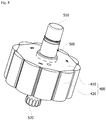
- FIG. 8 is a view illustrating a rotor.
- the rotor 400 is rotatably disposed inside the stator assembly 300.
- the rotor 400 is rotated by electromagnetic interaction with the stator assembly 300 due to a magnet 420 being mounted on a rotor core 410 thereof.
- a coil is wound around the stator assembly 300 so that the stator assembly 300 has a magnetic pole, and the rotor 400 is rotatable due to a magnetic field formed by the coil wound around the stator assembly 300.
- the rotary shaft 500 may be coupled to the center of the rotor 400. Accordingly, when the rotor 400 rotates, the rotary shaft 500 also rotates.
- the rotor 400 may be implemented to include the magnet 420 included in the rotor core 410 or to be attached to a circumferential surface of the rotor core 410 as illustrated in FIG. 8 .
- a sensor magnet 510 may be installed on a front end of one side of the rotary shaft 500.
- the sensor magnet 510 is for measuring a rotational speed of the motor 10.
- a spline groove 520 for connecting to the lead screw 40 (see FIG. 1 ) may be formed on a front end of the other end of the rotary shaft 500.
- the magnet 420 is mounted on the rotor core 410
- the sensor magnet 510 is mounted on the rotary shaft 500
- the rotor 400 coupled to the rotary shaft 500 may be formed by over-molding with plastic.
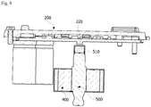
- FIG. 9 is a view illustrating a sensor magnet of a rotary shaft and a hall sensor of a control part disposed to face each other.
- a hall sensor 220 is provided at the control part 200, and the sensor magnet 510 is disposed to face the hall sensor 220.
- the control part 200 may directly measure the rotational speed of the motor 10 using the hall sensor 220.
- FIG. 10 is a view illustrating a sensor connecting part that is connected to a control part.
- the sensor connecting part 600 serves to transmit measurement information of a sensor installed in front of the housing 100 in which the actuator is mounted to the control part 200 disposed at a rear of the housing 100.
- the sensor connecting part 600 serves to secure a sensing space in which a state of the actuator may be easily measured in front of the housing 100.
- Such a sensor connecting part 600 may include a body 610 and a terminal 620.
- the body 610 serves to spatially connect the front of the housing 100 at which sensors are located to the rear of the housing 100 at which the control part 200 is located.
- a body 610 may mainly include a first body 610A and a second body 610B.
- the first body 610A and the second body 610B may be connected to be stepped, and may be divided and described only according to shapes and functional features thereof but may be a single unit in which the first body 610A and the second body 610B are connected.
- the first body 610A and the second body 610B may be implemented as blocks having hexagonal shapes.
- the first body 610A is a portion exposed in front of the housing 100
- the second body 610B is a portion located in the housing 100.
- the sensor mounting part 611 may be provided on the first body 610A.
- the sensor mounting part 611 may include a first mounting part 611 a and a second mounting part 611b.
- the first mounting part 611 a may be disposed on an upper surface of the first body 610A to face the center of the rotary shaft 500.
- the first mounting part 611a may be electrically connected to the terminal 620.
- a displacement sensor 700 may be mounted on the first mounting part 611a.
- the displacement sensor 700 may interact with the displacement sensor magnet 50 attached to the lead screw 40 to detect a position of the piston 30.
- the second mounting part 611b may be disposed on a front end of the first body 610A. In addition, the second mounting part 611b may be electrically connected to the terminal 620.
- the second mounting part 611b may be formed in a similar shape as the coupling slot 611ba (see FIG. 2 ) such that an inlet is formed to face forward.
- a pressure sensor 800 may be mounted on such a second mounting part 611b. As illustrated in FIG. 1 , the pressure sensor 800 is connected to the outlet 22 configured to discharge a working fluid to detect a hydraulic pressure applied to a clutch.
- the second body 610B may be located between the stator assembly 300 and an inner surface of the housing 100. Accordingly, a thickness of the second body 610B may be less than that of the first body 610A. In addition, the second body 610B may be physically connected to the control part 200.
- a connecting fin 610Ba connected to the terminal 620 and inserted into a connecting terminal of the control part 200 may be formed on an end of the second body 610B.
- the terminal 620 is disposed in the first body 610A and the second body 610B and is connected to the first mounting part 611 a, the second mounting part 611b, and the connecting fin 610Ba. Such a terminal 620 transmits position information of the lead screw 40 measured by the displacement sensor 700 and pressure information of the working fluid measured by the pressure sensor 800 to the control part 200.
- Such a sensor connecting part 600 is detachably coupled to the housing 100 in a form in which the sensor connecting part 600 is inserted into the housing 100 and directly connected to the control part, and thus connects the sensors such as the displacement sensor 700 and the pressure sensor 800, to the control part 200 with a simple structure.
- the sensor connecting part 600 is located inside the cover 20 in a state of being mounted on the housing 100, dustproofing and waterproofing reliability can be improved.
Landscapes
- Engineering & Computer Science (AREA)
- Power Engineering (AREA)
- General Engineering & Computer Science (AREA)
- Microelectronics & Electronic Packaging (AREA)
- Physics & Mathematics (AREA)
- Mechanical Engineering (AREA)
- General Physics & Mathematics (AREA)
- Fluid Mechanics (AREA)
- Connection Of Motors, Electrical Generators, Mechanical Devices, And The Like (AREA)
Abstract
Description
- The present invention relates to a motor, and more particularly, to a motor including a sensor connecting part configured to measure a state of an actuator, and a clutch actuator including the motor.
- A rotary shaft of a motor is connected to an actuator to transmit a driving force thereto. At this time, the motor and the actuator can be integrally manufactured according to characteristics of the actuator. For example, a driving shaft of the actuator and a rotary shaft of the motor can be integrally formed by forming the motor and the actuator together in one housing or using a tube-type rotor. In addition, a control module configured to control the motor according to a state of the actuator can be provided.
- However, the motor having such a structure has a problem in that a size of the motor is increased due to the tube-type rotor. In addition, sensors configured to measure the state of the actuator are connected to the control module, but an operation of connecting the sensors to the control module is difficult and a connecting structure thereof is complex, and thus there is a problem in that reliability of sensed information is reduced.
- Particularly, since the driving shaft of the actuator and the rotary shaft of the motor are integrally formed, there are problems in that precise position control is difficult, and compatibility of component replacement is reduced. In addition, since a large-sized bearing is installed at a side of the motor to overcome a load acting on the actuator, there is a problem in that the size of the motor is increased.
- The present invention is directed to providing a motor in which a driving shaft of an actuator and a rotary shaft of the motor are separately formed, a size thereof may be decreased, and sensors may be easily connected to a control module, and a clutch actuator including the motor.
- The scope of the present invention is not limited to the above-described objects, and other unmentioned objects may be clearly understood by those skilled in the art from the following descriptions.
- One aspect of the present invention provides a motor including a housing, a control part coupled to the housing, a stator assembly coupled to an inside of the housing and connected to the control part, a rotor disposed inside the stator, a rotary shaft coupled to the rotor, and a sensor connecting part including a body mounted on the housing and having a sensor mounting part, and a terminal included in the body and connected to the sensor mounting part and the control part, wherein the sensor mounting part is disposed outside the housing.
- The sensor mounting part may be disposed in front of the housing to which another component is connected.
- The control part may be disposed at a rear of the housing.
- The body may be directly connected to the control part so that the terminal is electrically connected to the control part.
- The sensor mounting part may include a first mounting part disposed to face a center of a shaft of the rotary shaft and a second mounting part disposed on a front end of the body.
- The motor may further include a displacement sensor mounted on the first mounting part, and a pressure sensor mounted on the second mounting part.
- The second mounting part may include a coupling slot in which an inlet is formed to face forward.
- The housing may include a mounting slot to which a body of the sensor connecting block is detachably coupled.
- The body may include a first body having the sensor mounting part and a second body inserted into the mounting slot and coupled to the control part.
- The first body and the second body may be coupled to be stepped.
- A connecting fin connected to the terminal and coupled to the control part may be formed on an end of the second body.
- The second body may be disposed between the stator assembly and an inner surface of the housing.
- The control part may be coupled to a rear surface of the housing.
- A power terminal of the stator may be directly connected to the control part.
- The rotor may be integrally molded with and is coupled to the first sensor magnet.
- A second sensor magnet may be coupled to a rear end of the rotary shaft, and the control part may include a hall sensor disposed to face the second sensor magnet.
- A power terminal, a neutral terminal connected to the power terminal and a coil, and a bearing may be integrally molded to form the stator assembly.
- Another aspect of the present invention provides a clutch actuator including a motor having a housing, a control part coupled to the housing, a stator assembly coupled to an inside of the housing and connected to the control part, a rotor disposed inside the stator, a rotary shaft coupled to the rotor, a body mounted on the housing and having a sensor mounting part, and a terminal included in the body and connected to the sensor mounting part and the control part, wherein the sensor mounting part is disposed outside the housing, a cover including a cylinder having an inlet and an outlet, and a piston connected to the rotary shaft to reciprocate in the cylinder.
- The sensor mounting part may include a first mounting part disposed to face a center of a shaft of the rotary shaft, and a second mounting part disposed on a front end of the body.
- The piston may include a displacement sensor magnet and a displacement sensor mounted on the first mounting part.
- The front end of the body may communicate with the outlet and include a pressure sensor mounted on the second mounting part.
- The clutch actuator may further include a lead screw configured to connect the piston and the rotary shaft.
- The cover may include a bearing configured to support the lead screw.
- According to one embodiment of the present invention, since mounted sensors are disposed outside a housing and a sensor connecting block mounted on the housing and directly connected to a control part is provided, a configuration and an operation of connecting the sensors to the control module are simplified, and thus there are advantageous effects in that efficiency of an assembly operation is increased and reliability of sensing information is improved.
- In addition, according to one embodiment of the present invention, since a rotary shaft of a motor and a driving shaft of an actuator are separately provided, there is an advantageous effect in that compatibility for component replacement is improved.
- In addition, according to one embodiment of the present invention, since a rotary shaft of a motor and a driving shaft of an actuator are separately provided and the rotary shaft of the motor is provided as a solid body, there is an advantageous effect in that a size of the motor can be decreased.
- In addition, according to one embodiment of the present invention, since a rear surface of a housing is formed as a control part so that the housing and the control part are integrally formed, there are advantageous effects in that an assembly structure thereof can be simplified and a size of a motor can be decreased.
- In addition, according to one embodiment of the present invention, since a bearing on which a load of an actuator is applied is installed at the actuator to support a lead screw, a size of a bearing installed at a motor is relatively decreased, and thus there is an advantageous effect in that a size of the motor is decreased.
- In addition, according to one embodiment of the present invention, since a sensor connecting block is detachably coupled to a housing to be directly connected to a control part, there is an advantageous effect in that an assembly thereof is facilitated.
-
-
FIG. 1 is a view illustrating a clutch actuator according to one exemplary embodiment of the present invention. -
FIG. 2 is a view illustrating a motor illustrated inFIG. 1 . -
FIG. 3 is an exploded view of the motor illustrated inFIG. 2 . -
FIG. 4 is a side cross-sectional view of the motor illustrated inFIG. 2 . -
FIG. 5 is a view illustrating a control part disposed on a rear surface of a housing. -
FIG. 6 is a view illustrating a stator assembly. -
FIG. 7 is a view illustrating a stator assembly that is directly connected to a control part. -
FIG. 8 is a view illustrating a rotor. -
FIG. 9 is a view illustrating a sensor magnet of a rotary shaft and a hall sensor of a control part disposed to face each other. -
FIG. 10 is a view illustrating a sensor connecting part that is connected to a control part. - Hereinafter, exemplary embodiments of the present invention will be described in detail with reference to the accompanying drawings. Purposes, specific advantages, and novel features of the present invention will be made clear from the exemplary embodiments and the following detailed description in connection with the accompanying drawings. Terms and words used in this specification and claims thereof are not to be interpreted as limited to commonly used meanings or meanings in dictionaries, and should be interpreted as having meanings and concepts which are consistent with the technological scope of the present invention based on the principle that the inventors have appropriately defined concepts of terms in order to describe the present invention in the best way. In the description of the present invention, when it is determined that detailed descriptions of related well-known functions unnecessarily obscure the gist of the present invention, the detailed descriptions will be omitted.
- It should be understood that, although the terms including ordinal numbers such as second, first, and the like may be used herein in reference to elements of the present invention, such elements are not to be construed as limited by these terms. These terms are only used to distinguish one element from another. For example, a second element could be termed a first element, and a first element could be termed a second element, without departing from the scope of the present invention. Herein, the term "and/or" includes any and all combinations of one or more referents.
-
FIG. 1 is a view illustrating a clutch actuator according to one exemplary embodiment of the present invention.FIG. 1 is a view clearly illustrating main features for a clear conceptual understanding of the present invention, and thus various modifications are expected and the scope of the present invention is not limited to specific shapes illustrated in the drawing. - Referring to
FIG. 1 , the clutch actuator according to one exemplary embodiment of the present invention may include amotor 10, acover 20, apiston 30, and alead screw 40. When themotor 10 is driven, thelead screw 40 rotates and thepiston 30 linearly moves as thelead screw 40 rotates. An accommodation space S for a fluid is provided inside thecover 20, and thepiston 30 is located in the accommodation space S. In addition, aninlet 21 and anoutlet 22 in communication with the accommodation space S may be formed in thecover 20. A working fluid is supplied to the accommodation space S through theinlet 21, and the working fluid is discharged from the accommodation space S through theoutlet 22. A working fluid pushed by thepiston 30 and discharged through theoutlet 22 may operate a clutch mounted on a vehicle. Meanwhile, adisplacement sensor magnet 50 may be installed at thelead screw 40. -
FIG. 2 is a view illustrating a motor illustrated inFIG. 1 ,FIG. 3 is an exploded view of the motor illustrated inFIG. 2 , andFIG. 4 is a side cross-sectional view of the motor illustrated inFIG. 2 .FIGS. 2 to 4 are views clearly illustrating main features for a clear conceptual understanding of the present invention, and thus various modifications are expected and the scope of the present invention is not limited to specific shapes illustrated in the drawings. - Referring to
FIGS. 1 to 4 , themotor 10 according to the exemplary embodiment of the present invention may include ahousing 100, acontrol part 200, astator assembly 300, arotor 400, arotary shaft 500, and asensor connecting part 600. - The
housing 100 is formed in a cylindrical shape so that a space in which thestator assembly 300, therotor 400, and the like may be installed is provided therein. Thehousing 100 is formed to be coupled to thecover 20. Here, although a shape or material of thehousing 100 may be variously changed, a metal material capable of easily withstanding a high temperature may be selected for thehousing 100 because thehousing 100 is installed in a vehicle. For example, one portion of thehousing 100, that is, a front surface of thehousing 100 connected to an actuator, may be made of aluminum. Alternatively, theentire housing 100 may be made of aluminum. - The actuator may be coupled to a side of the front surface of the
housing 100, and thecontrol part 200 may be coupled to a side of a rear surface of thehousing 100. In addition, a mountingslot 110 into which thesensor connecting part 600 is detachably inserted may be formed in the front surface of thehousing 100. - A
center hole 111 forming a space in which therotary shaft 500 is located and thelead screw 40 is connected to therotary shaft 500 may be provide at the center of thehousing 100, and the mountingslot 110 may be formed under thecenter hole 111. - The
control part 200 controls driving of themotor 10 on the basis of a state of the actuator transmitted from thesensor connecting part 600 and an external driving signal. Such acontrol part 200 may be integrally formed with the housing by being disposed at a rear of thehousing 100 as a rear cover of thehousing 100. -
FIG. 5 is a view illustrating a control part disposed on a rear surface of a housing. - Referring to
FIG. 5 , ahousing terminal 120 may be provided on the rear surface of thehousing 100. Thehousing terminal 120 may be disposed on a corner portion of thehousing 100. Thehousing terminal 120 may be electrically connected to an external power source. Meanwhile, aterminal insertion part 210 corresponding to such ahousing terminal 120 may be formed on a corner portion of thecontrol part 200. Thecontrol part 200 may be coupled to the rear surface of thehousing 100 so that thehousing terminal 120 is inserted into theterminal insertion part 210. - The
stator assembly 300 may include astator core 300a (seeFIG. 4 ), and acoil 300b (seeFIG. 4 ) configured to form a rotating magnetic field may be wound around thestator core 300a. Thecoil 300b wound around thestator core 300a may be insulated by being surrounded by aninsulator 300c (seeFIG. 4 ). -
FIG. 6 is a view illustrating a stator assembly. - Referring to
FIG. 6 , thestator assembly 300 may be implemented to include a bus bar and a bearing therein. Thestator assembly 300 may be formed by thestator core 300a (seeFIG. 4 ), thecoil 300b, and theinsulator 300c being integrally molded together so that apower terminal 310 and a connecting terminal of aneutral terminal 320 are exposed to the outside. Thestator assembly 300 may be formed by a bearing B2 being also integrally molded therewith together in a center thereof. A connecting terminal of one side of thepower terminal 310 is extended in a radial direction to be fused and connected to theneutral terminal 320. In addition, a connecting terminal of the other side of thepower terminal 310 may be formed to protrude upward to be directly connected to thecontrol part 200. -
FIG. 7 is a view illustrating a stator assembly that is directly connected to a control part. - Referring to
FIG. 7 ,power terminals 310 which protrude upward and have three phases may be assembled by being inserted into portions B of thecontrol part 200 and then fixed at portions B by a soldering. -
FIG. 8 is a view illustrating a rotor. - The
rotor 400 is rotatably disposed inside thestator assembly 300. Therotor 400 is rotated by electromagnetic interaction with thestator assembly 300 due to amagnet 420 being mounted on arotor core 410 thereof. For example, a coil is wound around thestator assembly 300 so that thestator assembly 300 has a magnetic pole, and therotor 400 is rotatable due to a magnetic field formed by the coil wound around thestator assembly 300. Therotary shaft 500 may be coupled to the center of therotor 400. Accordingly, when therotor 400 rotates, therotary shaft 500 also rotates. - The
rotor 400 may be implemented to include themagnet 420 included in therotor core 410 or to be attached to a circumferential surface of therotor core 410 as illustrated inFIG. 8 . In addition, asensor magnet 510 may be installed on a front end of one side of therotary shaft 500. Thesensor magnet 510 is for measuring a rotational speed of themotor 10. Meanwhile, aspline groove 520 for connecting to the lead screw 40 (seeFIG. 1 ) may be formed on a front end of the other end of therotary shaft 500. - In this way, the
magnet 420 is mounted on therotor core 410, thesensor magnet 510 is mounted on therotary shaft 500, and then therotor 400 coupled to therotary shaft 500 may be formed by over-molding with plastic. -
FIG. 9 is a view illustrating a sensor magnet of a rotary shaft and a hall sensor of a control part disposed to face each other. - Referring to
FIG. 9 , ahall sensor 220 is provided at thecontrol part 200, and thesensor magnet 510 is disposed to face thehall sensor 220. Thecontrol part 200 may directly measure the rotational speed of themotor 10 using thehall sensor 220. -
FIG. 10 is a view illustrating a sensor connecting part that is connected to a control part. - Referring to
FIGS. 2 ,4 , and10 , thesensor connecting part 600 serves to transmit measurement information of a sensor installed in front of thehousing 100 in which the actuator is mounted to thecontrol part 200 disposed at a rear of thehousing 100. In addition, thesensor connecting part 600 serves to secure a sensing space in which a state of the actuator may be easily measured in front of thehousing 100. - Such a
sensor connecting part 600 may include abody 610 and a terminal 620. - The
body 610 serves to spatially connect the front of thehousing 100 at which sensors are located to the rear of thehousing 100 at which thecontrol part 200 is located. Such abody 610 may mainly include afirst body 610A and asecond body 610B. Thefirst body 610A and thesecond body 610B may be connected to be stepped, and may be divided and described only according to shapes and functional features thereof but may be a single unit in which thefirst body 610A and thesecond body 610B are connected. - The
first body 610A and thesecond body 610B may be implemented as blocks having hexagonal shapes. In addition, when thesensor connecting part 600 is coupled to thehousing 100 through the mountingslot 110, thefirst body 610A is a portion exposed in front of thehousing 100, and thesecond body 610B is a portion located in thehousing 100. - The
sensor mounting part 611 may be provided on thefirst body 610A. Thesensor mounting part 611 may include a first mountingpart 611 a and a second mountingpart 611b. - The first mounting
part 611 a may be disposed on an upper surface of thefirst body 610A to face the center of therotary shaft 500. The first mountingpart 611a may be electrically connected to the terminal 620. - A
displacement sensor 700 may be mounted on the first mountingpart 611a. Thedisplacement sensor 700 may interact with thedisplacement sensor magnet 50 attached to thelead screw 40 to detect a position of thepiston 30. - The second mounting
part 611b may be disposed on a front end of thefirst body 610A. In addition, the second mountingpart 611b may be electrically connected to the terminal 620. - The second mounting
part 611b may be formed in a similar shape as the coupling slot 611ba (seeFIG. 2 ) such that an inlet is formed to face forward. Apressure sensor 800 may be mounted on such a second mountingpart 611b. As illustrated inFIG. 1 , thepressure sensor 800 is connected to theoutlet 22 configured to discharge a working fluid to detect a hydraulic pressure applied to a clutch. - The
second body 610B may be located between thestator assembly 300 and an inner surface of thehousing 100. Accordingly, a thickness of thesecond body 610B may be less than that of thefirst body 610A. In addition, thesecond body 610B may be physically connected to thecontrol part 200. - A connecting fin 610Ba connected to the terminal 620 and inserted into a connecting terminal of the
control part 200 may be formed on an end of thesecond body 610B. - The terminal 620 is disposed in the
first body 610A and thesecond body 610B and is connected to the first mountingpart 611 a, the second mountingpart 611b, and the connecting fin 610Ba. Such a terminal 620 transmits position information of thelead screw 40 measured by thedisplacement sensor 700 and pressure information of the working fluid measured by thepressure sensor 800 to thecontrol part 200. - Such a
sensor connecting part 600 is detachably coupled to thehousing 100 in a form in which thesensor connecting part 600 is inserted into thehousing 100 and directly connected to the control part, and thus connects the sensors such as thedisplacement sensor 700 and thepressure sensor 800, to thecontrol part 200 with a simple structure. In addition, since thesensor connecting part 600 is located inside thecover 20 in a state of being mounted on thehousing 100, dustproofing and waterproofing reliability can be improved. - The motor and the clutch actuator including the motor according to one exemplary embodiment of the present invention have been specifically described above with reference to the accompanying drawings.
- While the present invention has been particularly described with reference to exemplary embodiments, those skilled in the art should understand that various changes in form and details may be made without departing from the spirit and scope of the present invention. Therefore, the exemplary embodiments should be considered in a descriptive sense only and not for purposes of limitation. The scope of the present invention is defined not by the detailed description of the present invention but by the appended claims, and encompasses all modifications and equivalents that fall within the scope of the appended claims.
[Reference Numerals] 10: MOTOR 20: COVER 21: INLET 22: OUTLET 30: PISTON 40: LEAD SCREW 50: DISPLACEMENT SENSOR MAGNET 100: HOUSING 110: MOUNTING SLOT 111: CENTER HOLE 120: HOUSING TERMINAL 200: CONTROL PART 210: TERMINAL INSERTION PART 220: HALL SENSOR 300: STATOR ASSEMBLY 300A: STATOR CORE 300B: COIL 300C: INSULATOR 310: POWER TERMINAL 320: NEUTRAL TERMINAL 400: ROTOR 410: ROTOR CORE 420: MAGNET 500: ROTARY SHAFT 510: SENSOR MAGNET 520: SPLINE GROOVE 600: SENSOR CONNECTING PART 610: BODY 610A: FIRST BODY 610B: SECOND BODY 611: SENSOR MOUNTING PART 611A: FIRST MOUNTING PART 611B: SECOND MOUNTING PART 620: TERMINAL 700: DISPLACEMENT SENSOR 800: PRESSURE SENSOR
Claims (23)
- A motor comprising:a housing;a control part coupled to the housing;a stator assembly coupled to an inside of the housing and connected to the control part;a rotor disposed inside the stator;a rotary shaft coupled to the rotor; anda sensor connecting part including a body mounted on the housing and having a sensor mounting part, and a terminal included in the body and connected to the sensor mounting part and the control part,wherein the sensor mounting part is disposed outside the housing.
- The motor of claim 1, wherein the sensor mounting part is disposed in front of the housing to which another component is connected.
- The motor of claim 2, wherein the control part is disposed at a rear of the housing.
- The motor of claim 3, wherein the body is directly connected to the control part so that the terminal is electrically connected to the control part.
- The motor of claim 4, wherein the sensor mounting part includes:a first mounting part disposed to face a center of a shaft of the rotary shaft; anda second mounting part disposed on a front end of the body.
- The motor of claim 5, further comprising:a displacement sensor mounted on the first mounting part; anda pressure sensor mounted on the second mounting part.
- The motor of claim 6, wherein the second mounting part includes a coupling slot in which an inlet is formed to face forward.
- The motor of claim 1, wherein the housing includes a mounting slot to which a body of the sensor connecting block is detachably coupled.
- The motor of claim 8, wherein the body includes:a first body having the sensor mounting part; anda second body inserted into the mounting slot and coupled to the control part.
- The motor of claim 9, wherein the first body and the second body are coupled to be stepped.
- The motor of claim 8, wherein a connecting fin connected to the terminal and coupled to the control part is formed on an end of the second body.
- The motor of claim 1, wherein the second body is disposed between the stator assembly and an inner surface of the housing.
- The motor of claim 1, wherein the control part is coupled to a rear surface of the housing.
- The motor of claim 1, wherein a power terminal of the stator is directly connected to the control part.
- The motor of claim 1, wherein the rotor is integrally molded with and is coupled to the first sensor magnet.
- The motor of claim 1, wherein:a second sensor magnet is coupled to a rear end of the rotary shaft; andthe control part includes a hall sensor disposed to face the second sensor magnet.
- The motor of claim 1, wherein a power terminal, a neutral terminal connected to the power terminal and a coil, and a bearing are integrally molded to form the stator assembly.
- A clutch actuator comprising:a motor including a housing, a control part coupled to the housing, a stator assembly coupled to an inside of the housing and connected to the control part, a rotor disposed inside the stator, a rotary shaft coupled to the rotor, a body mounted on the housing and having a sensor mounting part, and a terminal included in the body and connected to the sensor mounting part and the control part, wherein the sensor mounting part is disposed outside the housing;a cover including a cylinder having an inlet and an outlet; anda piston connected to the rotary shaft to reciprocate in the cylinder.
- The clutch actuator of claim 18, wherein the sensor mounting part includes:a first mounting part disposed to face a center of a shaft of the rotary shaft; anda second mounting part disposed on a front end of the body.
- The clutch actuator of claim 19, wherein the piston includes:a displacement sensor magnet; anda displacement sensor mounted on the first mounting part.
- The clutch actuator of claim 20, wherein the front end of the body communicates with the outlet and includes a pressure sensor mounted on the second mounting part.
- The clutch actuator of claim 18, further comprising a lead screw configured to connect the piston and the rotary shaft.
- The clutch actuator of claim 22, wherein the cover includes a bearing configured to support the lead screw.
Applications Claiming Priority (2)
| Application Number | Priority Date | Filing Date | Title |
|---|---|---|---|
| KR1020140192403A KR102319204B1 (en) | 2014-12-29 | 2014-12-29 | Motor and Clutch actuator having the same |
| PCT/KR2015/008242 WO2016108379A1 (en) | 2014-12-29 | 2015-08-06 | Motor and clutch actuator including same |
Publications (3)
| Publication Number | Publication Date |
|---|---|
| EP3242380A1 true EP3242380A1 (en) | 2017-11-08 |
| EP3242380A4 EP3242380A4 (en) | 2018-07-25 |
| EP3242380B1 EP3242380B1 (en) | 2019-12-11 |
Family
ID=56284501
Family Applications (1)
| Application Number | Title | Priority Date | Filing Date |
|---|---|---|---|
| EP15875473.9A Active EP3242380B1 (en) | 2014-12-29 | 2015-08-06 | Motor and clutch actuator including same |
Country Status (6)
| Country | Link |
|---|---|
| US (1) | US10644567B2 (en) |
| EP (1) | EP3242380B1 (en) |
| JP (1) | JP6793124B2 (en) |
| KR (1) | KR102319204B1 (en) |
| CN (1) | CN107148724B (en) |
| WO (1) | WO2016108379A1 (en) |
Cited By (1)
| Publication number | Priority date | Publication date | Assignee | Title |
|---|---|---|---|---|
| WO2019001652A1 (en) * | 2017-06-28 | 2019-01-03 | Linak A/S | Linear actuator |
Families Citing this family (9)
| Publication number | Priority date | Publication date | Assignee | Title |
|---|---|---|---|---|
| US11067140B2 (en) * | 2017-05-03 | 2021-07-20 | Schaeffler Technologies AG & Co. KG | Method for operating an actuator arrangement for a clutch operating system, and actuator arrangement |
| KR102510334B1 (en) * | 2017-08-03 | 2023-03-15 | 엘지이노텍 주식회사 | Rotor and Motor having the same |
| CN111095737B (en) * | 2017-08-03 | 2022-08-30 | Lg伊诺特有限公司 | Rotor and motor including the same |
| DE102018219979A1 (en) * | 2018-11-22 | 2020-05-28 | Robert Bosch Gmbh | Electromotive drive device, brake actuator |
| CN110868013B (en) * | 2019-10-24 | 2021-06-08 | 深圳帆美智能科技有限公司 | Linear actuator and control method thereof |
| KR102116859B1 (en) * | 2019-12-27 | 2020-05-29 | 주식회사 컨트로맥스 | Jitter prevention system of Electro-mechanical actuator |
| NO347355B1 (en) * | 2020-11-24 | 2023-09-25 | Electrical Subsea & Drilling As | Device by actuator |
| WO2022114961A1 (en) * | 2020-11-24 | 2022-06-02 | Electrical Subsea & Drilling As | Actuator device |
| DE102021133952A1 (en) | 2021-12-21 | 2023-06-22 | Synapticon GmbH | Motor device with a multifunctional intermediate unit, which is arranged between a motor unit and a servo drive unit of the motor device |
Family Cites Families (27)
| Publication number | Priority date | Publication date | Assignee | Title |
|---|---|---|---|---|
| JP2862053B2 (en) | 1993-04-02 | 1999-02-24 | 三菱電機株式会社 | Motor with drive control device |
| JP3040052B2 (en) | 1994-05-09 | 2000-05-08 | 株式会社フジユニバンス | Transfer device |
| GB9619175D0 (en) * | 1996-09-13 | 1996-10-23 | Lucas Ind Plc | Electrical power-assisted steering systems |
| JPH10129445A (en) | 1996-10-25 | 1998-05-19 | Nisshinbo Ind Inc | Hydraulic controller |
| DE19701739A1 (en) * | 1997-01-20 | 1998-07-23 | Bosch Gmbh Robert | Actuator |
| US6593674B2 (en) * | 2001-02-26 | 2003-07-15 | Woodward Governor Company | Vibration isolator and actuator incorporating same for isolating integral electronics |
| JP2005176526A (en) | 2003-12-12 | 2005-06-30 | Nsk Ltd | Electric actuator |
| JP4615405B2 (en) * | 2004-11-22 | 2011-01-19 | 日立オートモティブシステムズ株式会社 | Motor control device, power steering device and braking force control device |
| KR20060101609A (en) | 2005-03-21 | 2006-09-26 | 임재옥 | Small motor reducer |
| DE102007045815A1 (en) * | 2007-09-25 | 2009-04-09 | Magna Powertrain Ag & Co Kg | gear unit |
| JP5195360B2 (en) | 2008-01-24 | 2013-05-08 | 株式会社アドヴィックス | Brake hydraulic pressure control device |
| KR200470310Y1 (en) | 2008-12-15 | 2013-12-06 | 엘지이노텍 주식회사 | Sensor of steering apparatus for a car |
| DE112010004215A5 (en) | 2009-10-29 | 2012-08-23 | Schaeffler Technologies AG & Co. KG | HYDROSTATAKTOR |
| JP5417132B2 (en) | 2009-11-26 | 2014-02-12 | Ntn株式会社 | Electric actuator |
| CN102118078A (en) * | 2009-12-30 | 2011-07-06 | 德昌电机(深圳)有限公司 | Motor driving assembly |
| DE112011101281B4 (en) * | 2010-04-12 | 2022-03-03 | Schaeffler Technologies AG & Co. KG | hydrostatic actuator |
| EP2580850B1 (en) * | 2010-06-14 | 2021-11-10 | Black & Decker, Inc. | Control unit for brushless motor in a power tool |
| JP2012147519A (en) * | 2011-01-07 | 2012-08-02 | Mitsuba Corp | Motor device |
| JP5775853B2 (en) * | 2011-11-16 | 2015-09-09 | 日本電産テクノモータ株式会社 | Molded motor |
| US9190888B2 (en) | 2012-04-13 | 2015-11-17 | Globe Motors, Inc. | Method of positioning a sensor within a motor assembly |
| EA020935B1 (en) * | 2012-05-11 | 2015-02-27 | Зао "Диаконт" | Electromechanical driving actuator with damping device |
| DE102013201473A1 (en) | 2013-01-30 | 2014-07-31 | Schaeffler Technologies Gmbh & Co. Kg | Actuating system for clutch of motor vehicle, has gear box including driven threaded spindle which is operatively connected with piston by hydrostatic clutch actuator nut, and sensor element which detects position of nut |
| US8985253B2 (en) * | 2013-02-05 | 2015-03-24 | Honda Motor Co., Ltd. | Generators and vehicles having auxiliary power generation systems |
| WO2015192040A1 (en) * | 2014-06-13 | 2015-12-17 | Tolomatic, Inc. | Coupled capacitive and magnetic servo motor systems |
| EP3206284A4 (en) * | 2014-10-07 | 2018-10-03 | Nidec Sankyo Corporation | Tubular motor, brushless motor control method, and motor with brake |
| US10227872B2 (en) * | 2015-10-22 | 2019-03-12 | Nidec Motor Corporation | Internal bearing plate for gearmotor assembly |
| US20180062479A1 (en) * | 2016-08-24 | 2018-03-01 | Cts Corporation | Modular Vehicle Engine Component Actuator |
-
2014
- 2014-12-29 KR KR1020140192403A patent/KR102319204B1/en active Active
-
2015
- 2015-08-06 EP EP15875473.9A patent/EP3242380B1/en active Active
- 2015-08-06 CN CN201580071821.7A patent/CN107148724B/en active Active
- 2015-08-06 WO PCT/KR2015/008242 patent/WO2016108379A1/en not_active Ceased
- 2015-08-06 JP JP2017535438A patent/JP6793124B2/en active Active
- 2015-08-06 US US15/540,945 patent/US10644567B2/en active Active
Cited By (1)
| Publication number | Priority date | Publication date | Assignee | Title |
|---|---|---|---|---|
| WO2019001652A1 (en) * | 2017-06-28 | 2019-01-03 | Linak A/S | Linear actuator |
Also Published As
| Publication number | Publication date |
|---|---|
| US10644567B2 (en) | 2020-05-05 |
| KR20160080503A (en) | 2016-07-08 |
| WO2016108379A1 (en) | 2016-07-07 |
| JP2018502546A (en) | 2018-01-25 |
| EP3242380B1 (en) | 2019-12-11 |
| EP3242380A4 (en) | 2018-07-25 |
| CN107148724B (en) | 2019-11-08 |
| US20170358970A1 (en) | 2017-12-14 |
| JP6793124B2 (en) | 2020-12-02 |
| KR102319204B1 (en) | 2021-10-29 |
| CN107148724A (en) | 2017-09-08 |
Similar Documents
| Publication | Publication Date | Title |
|---|---|---|
| EP3242380B1 (en) | Motor and clutch actuator including same | |
| US11201525B2 (en) | Motor and pump assembly for a brake system | |
| CN103124666B (en) | The deflector comprising electrical motor, control unit and sensing device and the electric power steering system of being furnished with deflector | |
| CN105993117B (en) | motor | |
| US20110273121A1 (en) | Electric Machine Component Temperature Monitoring | |
| US20210277894A1 (en) | Pump device | |
| JP2013530669A (en) | Pump magnet housing with integrated sensor element | |
| CN102944345A (en) | Portable tool with wireless measured value transmission | |
| US20190234404A1 (en) | Pump device | |
| WO2016068073A1 (en) | Drive device | |
| JP7432706B2 (en) | Brushless DC electric motor for automotive wiper system | |
| JP2020515214A (en) | Brushless electromechanical | |
| CN108662038B (en) | Actuator and electronic clutch system using same | |
| JP4475710B2 (en) | Linear drive | |
| JP7281641B2 (en) | Motor unit and electric oil pump | |
| CN111226384B (en) | Electric motor vehicle fluid pump | |
| US20180172476A1 (en) | Sensor arrangement having a modular structure | |
| US20190032656A1 (en) | Electric oil pump | |
| US11005351B2 (en) | Automotive electric fluidic pump | |
| JP7158457B2 (en) | axial piston pump | |
| CN105840579A (en) | Fluid handling device | |
| CN203457023U (en) | Stepper motor | |
| KR102361356B1 (en) | Displacement measurement apparatus and motor including the same | |
| JP2006322779A (en) | Rotor and motor | |
| WO2025194484A1 (en) | Electric oil pump |
Legal Events
| Date | Code | Title | Description |
|---|---|---|---|
| STAA | Information on the status of an ep patent application or granted ep patent |
Free format text: STATUS: THE INTERNATIONAL PUBLICATION HAS BEEN MADE |
|
| PUAI | Public reference made under article 153(3) epc to a published international application that has entered the european phase |
Free format text: ORIGINAL CODE: 0009012 |
|
| STAA | Information on the status of an ep patent application or granted ep patent |
Free format text: STATUS: REQUEST FOR EXAMINATION WAS MADE |
|
| 17P | Request for examination filed |
Effective date: 20170629 |
|
| AK | Designated contracting states |
Kind code of ref document: A1 Designated state(s): AL AT BE BG CH CY CZ DE DK EE ES FI FR GB GR HR HU IE IS IT LI LT LU LV MC MK MT NL NO PL PT RO RS SE SI SK SM TR |
|
| AX | Request for extension of the european patent |
Extension state: BA ME |
|
| DAV | Request for validation of the european patent (deleted) | ||
| DAX | Request for extension of the european patent (deleted) | ||
| A4 | Supplementary search report drawn up and despatched |
Effective date: 20180625 |
|
| RIC1 | Information provided on ipc code assigned before grant |
Ipc: H02K 17/32 20060101ALI20180619BHEP Ipc: F16H 25/20 20060101ALN20180619BHEP Ipc: H02K 7/11 20060101ALI20180619BHEP Ipc: H02K 11/20 20160101ALI20180619BHEP Ipc: H02K 7/116 20060101ALI20180619BHEP Ipc: F16D 29/00 20060101ALI20180619BHEP Ipc: H02K 11/00 20160101AFI20180619BHEP Ipc: H02K 7/06 20060101ALN20180619BHEP Ipc: F15B 7/08 20060101ALN20180619BHEP Ipc: H02K 5/22 20060101ALI20180619BHEP Ipc: H02K 11/38 20160101ALI20180619BHEP Ipc: H02K 7/108 20060101ALI20180619BHEP |
|
| RIC1 | Information provided on ipc code assigned before grant |
Ipc: H02K 11/38 20160101ALI20190520BHEP Ipc: H02K 7/11 20060101ALI20190520BHEP Ipc: F16H 25/20 20060101ALN20190520BHEP Ipc: G01D 5/14 20060101ALN20190520BHEP Ipc: H02K 11/20 20160101ALI20190520BHEP Ipc: H02K 7/108 20060101ALI20190520BHEP Ipc: H02K 7/116 20060101ALI20190520BHEP Ipc: H02K 11/215 20160101ALI20190520BHEP Ipc: H02K 17/32 20060101ALI20190520BHEP Ipc: H02K 11/00 20160101AFI20190520BHEP Ipc: F16D 29/00 20060101ALI20190520BHEP Ipc: H02K 11/33 20160101ALI20190520BHEP Ipc: H02K 7/06 20060101ALN20190520BHEP Ipc: F16D 25/08 20060101ALI20190520BHEP Ipc: H02K 5/22 20060101ALI20190520BHEP Ipc: F15B 7/08 20060101ALN20190520BHEP |
|
| GRAP | Despatch of communication of intention to grant a patent |
Free format text: ORIGINAL CODE: EPIDOSNIGR1 |
|
| STAA | Information on the status of an ep patent application or granted ep patent |
Free format text: STATUS: GRANT OF PATENT IS INTENDED |
|
| INTG | Intention to grant announced |
Effective date: 20190703 |
|
| GRAS | Grant fee paid |
Free format text: ORIGINAL CODE: EPIDOSNIGR3 |
|
| GRAA | (expected) grant |
Free format text: ORIGINAL CODE: 0009210 |
|
| STAA | Information on the status of an ep patent application or granted ep patent |
Free format text: STATUS: THE PATENT HAS BEEN GRANTED |
|
| AK | Designated contracting states |
Kind code of ref document: B1 Designated state(s): AL AT BE BG CH CY CZ DE DK EE ES FI FR GB GR HR HU IE IS IT LI LT LU LV MC MK MT NL NO PL PT RO RS SE SI SK SM TR |
|
| REG | Reference to a national code |
Ref country code: GB Ref legal event code: FG4D |
|
| REG | Reference to a national code |
Ref country code: CH Ref legal event code: EP |
|
| REG | Reference to a national code |
Ref country code: AT Ref legal event code: REF Ref document number: 1213164 Country of ref document: AT Kind code of ref document: T Effective date: 20191215 |
|
| REG | Reference to a national code |
Ref country code: DE Ref legal event code: R096 Ref document number: 602015043646 Country of ref document: DE |
|
| REG | Reference to a national code |
Ref country code: IE Ref legal event code: FG4D |
|
| REG | Reference to a national code |
Ref country code: NL Ref legal event code: MP Effective date: 20191211 |
|
| REG | Reference to a national code |
Ref country code: LT Ref legal event code: MG4D |
|
| PG25 | Lapsed in a contracting state [announced via postgrant information from national office to epo] |
Ref country code: NO Free format text: LAPSE BECAUSE OF FAILURE TO SUBMIT A TRANSLATION OF THE DESCRIPTION OR TO PAY THE FEE WITHIN THE PRESCRIBED TIME-LIMIT Effective date: 20200311 Ref country code: GR Free format text: LAPSE BECAUSE OF FAILURE TO SUBMIT A TRANSLATION OF THE DESCRIPTION OR TO PAY THE FEE WITHIN THE PRESCRIBED TIME-LIMIT Effective date: 20200312 Ref country code: BG Free format text: LAPSE BECAUSE OF FAILURE TO SUBMIT A TRANSLATION OF THE DESCRIPTION OR TO PAY THE FEE WITHIN THE PRESCRIBED TIME-LIMIT Effective date: 20200311 Ref country code: FI Free format text: LAPSE BECAUSE OF FAILURE TO SUBMIT A TRANSLATION OF THE DESCRIPTION OR TO PAY THE FEE WITHIN THE PRESCRIBED TIME-LIMIT Effective date: 20191211 Ref country code: LT Free format text: LAPSE BECAUSE OF FAILURE TO SUBMIT A TRANSLATION OF THE DESCRIPTION OR TO PAY THE FEE WITHIN THE PRESCRIBED TIME-LIMIT Effective date: 20191211 Ref country code: LV Free format text: LAPSE BECAUSE OF FAILURE TO SUBMIT A TRANSLATION OF THE DESCRIPTION OR TO PAY THE FEE WITHIN THE PRESCRIBED TIME-LIMIT Effective date: 20191211 Ref country code: SE Free format text: LAPSE BECAUSE OF FAILURE TO SUBMIT A TRANSLATION OF THE DESCRIPTION OR TO PAY THE FEE WITHIN THE PRESCRIBED TIME-LIMIT Effective date: 20191211 |
|
| PG25 | Lapsed in a contracting state [announced via postgrant information from national office to epo] |
Ref country code: HR Free format text: LAPSE BECAUSE OF FAILURE TO SUBMIT A TRANSLATION OF THE DESCRIPTION OR TO PAY THE FEE WITHIN THE PRESCRIBED TIME-LIMIT Effective date: 20191211 Ref country code: RS Free format text: LAPSE BECAUSE OF FAILURE TO SUBMIT A TRANSLATION OF THE DESCRIPTION OR TO PAY THE FEE WITHIN THE PRESCRIBED TIME-LIMIT Effective date: 20191211 |
|
| PG25 | Lapsed in a contracting state [announced via postgrant information from national office to epo] |
Ref country code: AL Free format text: LAPSE BECAUSE OF FAILURE TO SUBMIT A TRANSLATION OF THE DESCRIPTION OR TO PAY THE FEE WITHIN THE PRESCRIBED TIME-LIMIT Effective date: 20191211 |
|
| PG25 | Lapsed in a contracting state [announced via postgrant information from national office to epo] |
Ref country code: PT Free format text: LAPSE BECAUSE OF FAILURE TO SUBMIT A TRANSLATION OF THE DESCRIPTION OR TO PAY THE FEE WITHIN THE PRESCRIBED TIME-LIMIT Effective date: 20200506 Ref country code: RO Free format text: LAPSE BECAUSE OF FAILURE TO SUBMIT A TRANSLATION OF THE DESCRIPTION OR TO PAY THE FEE WITHIN THE PRESCRIBED TIME-LIMIT Effective date: 20191211 Ref country code: CZ Free format text: LAPSE BECAUSE OF FAILURE TO SUBMIT A TRANSLATION OF THE DESCRIPTION OR TO PAY THE FEE WITHIN THE PRESCRIBED TIME-LIMIT Effective date: 20191211 Ref country code: ES Free format text: LAPSE BECAUSE OF FAILURE TO SUBMIT A TRANSLATION OF THE DESCRIPTION OR TO PAY THE FEE WITHIN THE PRESCRIBED TIME-LIMIT Effective date: 20191211 Ref country code: NL Free format text: LAPSE BECAUSE OF FAILURE TO SUBMIT A TRANSLATION OF THE DESCRIPTION OR TO PAY THE FEE WITHIN THE PRESCRIBED TIME-LIMIT Effective date: 20191211 Ref country code: EE Free format text: LAPSE BECAUSE OF FAILURE TO SUBMIT A TRANSLATION OF THE DESCRIPTION OR TO PAY THE FEE WITHIN THE PRESCRIBED TIME-LIMIT Effective date: 20191211 |
|
| PG25 | Lapsed in a contracting state [announced via postgrant information from national office to epo] |
Ref country code: SM Free format text: LAPSE BECAUSE OF FAILURE TO SUBMIT A TRANSLATION OF THE DESCRIPTION OR TO PAY THE FEE WITHIN THE PRESCRIBED TIME-LIMIT Effective date: 20191211 Ref country code: SK Free format text: LAPSE BECAUSE OF FAILURE TO SUBMIT A TRANSLATION OF THE DESCRIPTION OR TO PAY THE FEE WITHIN THE PRESCRIBED TIME-LIMIT Effective date: 20191211 Ref country code: IS Free format text: LAPSE BECAUSE OF FAILURE TO SUBMIT A TRANSLATION OF THE DESCRIPTION OR TO PAY THE FEE WITHIN THE PRESCRIBED TIME-LIMIT Effective date: 20200411 |
|
| REG | Reference to a national code |
Ref country code: DE Ref legal event code: R097 Ref document number: 602015043646 Country of ref document: DE |
|
| REG | Reference to a national code |
Ref country code: AT Ref legal event code: MK05 Ref document number: 1213164 Country of ref document: AT Kind code of ref document: T Effective date: 20191211 |
|
| PLBE | No opposition filed within time limit |
Free format text: ORIGINAL CODE: 0009261 |
|
| STAA | Information on the status of an ep patent application or granted ep patent |
Free format text: STATUS: NO OPPOSITION FILED WITHIN TIME LIMIT |
|
| PG25 | Lapsed in a contracting state [announced via postgrant information from national office to epo] |
Ref country code: DK Free format text: LAPSE BECAUSE OF FAILURE TO SUBMIT A TRANSLATION OF THE DESCRIPTION OR TO PAY THE FEE WITHIN THE PRESCRIBED TIME-LIMIT Effective date: 20191211 |
|
| 26N | No opposition filed |
Effective date: 20200914 |
|
| PG25 | Lapsed in a contracting state [announced via postgrant information from national office to epo] |
Ref country code: SI Free format text: LAPSE BECAUSE OF FAILURE TO SUBMIT A TRANSLATION OF THE DESCRIPTION OR TO PAY THE FEE WITHIN THE PRESCRIBED TIME-LIMIT Effective date: 20191211 Ref country code: AT Free format text: LAPSE BECAUSE OF FAILURE TO SUBMIT A TRANSLATION OF THE DESCRIPTION OR TO PAY THE FEE WITHIN THE PRESCRIBED TIME-LIMIT Effective date: 20191211 |
|
| PG25 | Lapsed in a contracting state [announced via postgrant information from national office to epo] |
Ref country code: IT Free format text: LAPSE BECAUSE OF FAILURE TO SUBMIT A TRANSLATION OF THE DESCRIPTION OR TO PAY THE FEE WITHIN THE PRESCRIBED TIME-LIMIT Effective date: 20191211 |
|
| PG25 | Lapsed in a contracting state [announced via postgrant information from national office to epo] |
Ref country code: PL Free format text: LAPSE BECAUSE OF FAILURE TO SUBMIT A TRANSLATION OF THE DESCRIPTION OR TO PAY THE FEE WITHIN THE PRESCRIBED TIME-LIMIT Effective date: 20191211 |
|
| PG25 | Lapsed in a contracting state [announced via postgrant information from national office to epo] |
Ref country code: MC Free format text: LAPSE BECAUSE OF FAILURE TO SUBMIT A TRANSLATION OF THE DESCRIPTION OR TO PAY THE FEE WITHIN THE PRESCRIBED TIME-LIMIT Effective date: 20191211 |
|
| REG | Reference to a national code |
Ref country code: CH Ref legal event code: PL |
|
| GBPC | Gb: european patent ceased through non-payment of renewal fee |
Effective date: 20200806 |
|
| PG25 | Lapsed in a contracting state [announced via postgrant information from national office to epo] |
Ref country code: LU Free format text: LAPSE BECAUSE OF NON-PAYMENT OF DUE FEES Effective date: 20200806 Ref country code: LI Free format text: LAPSE BECAUSE OF NON-PAYMENT OF DUE FEES Effective date: 20200831 Ref country code: CH Free format text: LAPSE BECAUSE OF NON-PAYMENT OF DUE FEES Effective date: 20200831 |
|
| REG | Reference to a national code |
Ref country code: BE Ref legal event code: MM Effective date: 20200831 |
|
| PG25 | Lapsed in a contracting state [announced via postgrant information from national office to epo] |
Ref country code: BE Free format text: LAPSE BECAUSE OF NON-PAYMENT OF DUE FEES Effective date: 20200831 Ref country code: IE Free format text: LAPSE BECAUSE OF NON-PAYMENT OF DUE FEES Effective date: 20200806 Ref country code: GB Free format text: LAPSE BECAUSE OF NON-PAYMENT OF DUE FEES Effective date: 20200806 |
|
| PG25 | Lapsed in a contracting state [announced via postgrant information from national office to epo] |
Ref country code: TR Free format text: LAPSE BECAUSE OF FAILURE TO SUBMIT A TRANSLATION OF THE DESCRIPTION OR TO PAY THE FEE WITHIN THE PRESCRIBED TIME-LIMIT Effective date: 20191211 Ref country code: MT Free format text: LAPSE BECAUSE OF FAILURE TO SUBMIT A TRANSLATION OF THE DESCRIPTION OR TO PAY THE FEE WITHIN THE PRESCRIBED TIME-LIMIT Effective date: 20191211 Ref country code: CY Free format text: LAPSE BECAUSE OF FAILURE TO SUBMIT A TRANSLATION OF THE DESCRIPTION OR TO PAY THE FEE WITHIN THE PRESCRIBED TIME-LIMIT Effective date: 20191211 |
|
| PG25 | Lapsed in a contracting state [announced via postgrant information from national office to epo] |
Ref country code: MK Free format text: LAPSE BECAUSE OF FAILURE TO SUBMIT A TRANSLATION OF THE DESCRIPTION OR TO PAY THE FEE WITHIN THE PRESCRIBED TIME-LIMIT Effective date: 20191211 |
|
| PGFP | Annual fee paid to national office [announced via postgrant information from national office to epo] |
Ref country code: DE Payment date: 20250721 Year of fee payment: 11 |
|
| PGFP | Annual fee paid to national office [announced via postgrant information from national office to epo] |
Ref country code: FR Payment date: 20250725 Year of fee payment: 11 |