EP3242279A1 - Monitoring system and method - Google Patents
Monitoring system and method Download PDFInfo
- Publication number
- EP3242279A1 EP3242279A1 EP16168550.8A EP16168550A EP3242279A1 EP 3242279 A1 EP3242279 A1 EP 3242279A1 EP 16168550 A EP16168550 A EP 16168550A EP 3242279 A1 EP3242279 A1 EP 3242279A1
- Authority
- EP
- European Patent Office
- Prior art keywords
- zone
- person
- exclusion zone
- warning
- exclusion
- Prior art date
- Legal status (The legal status is an assumption and is not a legal conclusion. Google has not performed a legal analysis and makes no representation as to the accuracy of the status listed.)
- Granted
Links
Images


Classifications
-
- G—PHYSICS
- G08—SIGNALLING
- G08B—SIGNALLING SYSTEMS, e.g. PERSONAL CALLING SYSTEMS; ORDER TELEGRAPHS; ALARM SYSTEMS
- G08B21/00—Alarms responsive to a single specified undesired or abnormal condition and not otherwise provided for
- G08B21/18—Status alarms
- G08B21/22—Status alarms responsive to presence or absence of persons
Definitions
- the invention relates to a monitoring system for monitoring a first person's position and a corresponding method.
- ankle monitors also known as tether or ankle bracelet.
- Such ankle monitors are homing devices, which can e.g. be used to monitor a position of a person, when the ankle monitor is worn by the person, e.g. on the ankle.
- Ankle monitors usually comprise a position sensor, like e.g. a GPS-sensor, to determine the person's position.
- a position sensor like e.g. a GPS-sensor
- ankle monitors can be used at least in two configurations. In a first configuration, a zone is defined, which the person may not leave. As soon as the person leaves the defined zone an alarm is sent e.g. to the next police patrol.
- the ankle monitor can be used to monitor that the person does not enter a predefined spatial zone.
- This configuration can e.g. be used to protect stalker victims from the stalker, e.g. after a court has issued a restraining order or protective order.
- the present invention provides a monitoring system with the features of claim 1 and a monitoring method with the features of claim 7.
- the monitoring system for monitoring a first person's position comprises a first position sensor configured to monitor the first person's position and provide a respective first position signal.
- the monitoring system further comprises a position monitor configured to monitor based on the first position signal if the first person enters a spatially defined warning zone or a spatially defined exclusion zone, which is a sub-zone of the warning zone.
- the position monitor is configured to provide a warning signal if the first person enters the warning zone and provide a disobey signal if the first person enters the exclusion zone.
- the monitoring system further comprises a modification unit, which is configured to spatially modify the warning zone and/or the exclusion zone based on the distance of at least one mobile support unit, like e.g. a police officer, a police patrol, other security personnel, or e.g. an ambulance, from the warning zone and/or the exclusion zone.
- the monitoring method for monitoring a first person's position comprises the steps of monitoring the first person's position and provide a respective first position signal, and monitoring based on the first position signal if the first person enters a spatially defined warning zone or a spatially defined exclusion zone, which is a sub-zone of the warning zone.
- the method further comprises providing a warning signal if the first person enters the warning zone and provide a disobey signal if the first person enters the exclusion zone, and spatially modifying the warning zone and/or the exclusion zone based on the distance of at least one mobile support unit from the warning zone and/or the exclusion zone.
- the monitoring system can be used e.g. to monitor a person that for certain reasons may not enter a specific area or zone. Such a person can e.g. be an offender who may not approach his former victim up to more than a certain distance.
- zone refers to a geographic or spatial area or zone.
- Such zones can be defined e.g. in a component of the monitoring system, e.g. the position monitor.
- geographic coordinates can be stored in the position monitor, which define the zones.
- a further possibility is to store a center of a zone as a geographic coordinate and a corresponding radius.
- the first position sensor and/or the position monitor can e.g. be provided in an ankle monitor, tether or ankle bracelet. It is also possible to integrate the modification unit in the ankle monitor, tether or ankle bracelet. Alternatively, some or all of these components can also be implemented in other devices, like e.g. a mobile phone or another unit, which can be carried by the first person or fixed to the first person's body. Alternatively only the first position sensor can be provided in the ankle monitor and the position monitor and the modification unit can e.g. be provided in a server or a control room.
- a violation of the exclusion zone by the first person is signaled by the position monitor via the disobey signal.
- the disobey signal when received e.g. by security personnel, requires immediate action e.g. by the police, because the disobey signal indicates that the first person violated the imposed stipulations.
- the present invention provides another zone, the so-called warning zone.
- the warning zone will usually be spatially larger than the exclusion zone and comprise the exclusion zone, i.e. the exclusion zone is a subset of the warning zone. If the first person enters the warning zone, the position monitor generates the warning signal.
- the warning signal indicates to the first person that he/she is progressing towards the exclusion zone.
- the warning signal can e.g. be provided to the mobile support units as well as the first person and gives the first person the chance to turn away from the exclusion zone.
- the present invention uses the finding that it is difficult to define fixed areas or zones as the warning zone and the exclusion zone, which may excessively limit the first person's freedom of movement, especially e.g. in small cities or villages.
- defining a very small warning zone and a very small exclusion zone may put the person or object to be protected in risk.
- the present invention therefore provides adaptive zones, i.e. the size of the warning zone and the exclusion zone are adaptively varied according to a position of a mobile support unit to the warning zone and/or the exclusion zone, i.e. the person or object to be protected.
- the components of the monitoring system can be provided in a computer or processor, e.g. as functions or computer programs.
- any type of position sensor e.g. a GPS sensor
- position sensors can be used, which are already present in the mobile support units. For example, police cars, ambulances and single police officers may already carry GPS sensors and their positions may therefore be known.
- the size of the warning zone and the exclusion zone may therefore vary such that the mobile support unit will reach the exclusion zone in time before the first person can deal any damage.
- the present invention therefore allows providing the first person with the maximum freedom, while increasing the safety of the protectee.
- the modification unit can be configured to spatially increase the warning zone and/or the exclusion zone if the mobile support units are located at a distance from the exclusion zone, which is higher than a predetermined threshold value.
- the predetermined threshold value can e.g. define a distance, where it is safe to suppose that the support unit will reach the exclusion zone in time to apprehend the first person for violating the exclusion zone, before the first person reaches the center of the exclusion zone, i.e. the person or object to be protected.
- the amount of increase of the sizes of the warning zone and/or the exclusion zone can be linearly related to the distance of the support unit. If e.g.
- the size of the warning zone can e.g. be calculated as 2km/1km * (minimum size).
- An analogous scheme can be applied for the exclusion zone.
- maximum sizes can be provided for the warning zone and/or the exclusion zone.
- a table may be provided, which provides specific sizes of the warning zone and/or the exclusion zone for specific distances of the mobile support units.
- the modification unit can be configured to retrieve traffic information and calculate a travel time for the mobile support units to the exclusion zone. Further, the modification unit can be configured to modify the size of the warning zone and/or the exclusion zone based on the calculated travel time. In one example, a mean speed of movement can be assumed for the first person. The sizes of the warning zone and/or the exclusion zone can be adapted such that the mobile support units will reach the exclusion zone or it's center in the travel time and at the same time as the first person if he/she approaches the exclusion zone. If for example the modification unit calculates that a police patrol is 5 minutes away from the center of the exclusion zone. The speed of movement of the first person may be assumed to be 5km/h (1,39m/s).
- the radius of the warning zone may be set to about 417m.
- an additional security margin e.g. +5% - +10%, may be added to the determined size.
- the mobile support unit must move towards the center of the exclusion zone as soon as the warning signal is provided.
- the radius of the exclusion zone can be set to the calculated value and the size of the warning zone may be the size of the exclusion zone multiplied by a given fixed or variable factor. The factor may e.g. increase with increasing size of the exclusion zone. This will always provide the mobile support unit with enough time to arrive at the center of the exclusion zone before the first person.
- the necessary traffic information can e.g. be retrieved from publically available data sources via the internet.
- certain navigation system publishers also provide real time traffic information via their services, which can be retrieved via public APIs, such as via a google maps API.
- Such information can also be retrieved from official databases, as e.g. police operated databases or databases of traffic institutes. Calculating the travel time can e.g. simply comprise a route calculation, online or offline.
- the first position sensor can be configured to determine the direction of movement and speed of movement of the first person.
- the modification unit can be configured to calculate the time of travel of the first person to the center of the exclusion zone based on the determined direction of movement and speed of movement.
- the modification unit can be configured to adapt the size of the warning zone and/or exclusion zone based on the travel time of the mobile support units to the exclusion zone and the time of travel of the first person to the center of the exclusion zone.
- the size of the exclusion zone can e.g. be set such that a mobile support unit will reach the center of the exclusion zone before the first person, if the mobile support unit initiates movement as soon as the disobey signal is received. If for example a police patrol is 5 minutes away from the center of the exclusion zone, the size of the exclusion zone will be set such that the first person will need 5 minutes to arrive at the center of the exclusion zone with the determined speed.
- the monitoring system can comprise a second position sensor configured to monitor the position of a protectee, e.g. a person or an object, wherein the modification unit is configured to set the center of the exclusion zone to the position of the protectee.
- Monitoring the position of a protectee allows automatically following the protectee with the warning zone and the exclusion zone. This provides full freedom of movement to the protectee and at the same time maximum security.
- the first position sensor and/or the second position sensor can comprise wireless position sensors, as e.g. GPS sensors, Cell Phone based position sensors, Bluetooth based position sensor, like iBeacons.
- the first position sensor and/or the second position sensor can each comprise a communication interface, e.g. a GSM interface, UMTS interface, LTE interface, WIFI interface or the like, and can be configured provide the position information to a data server.
- the data server may e.g. be accessible via the internet and may comprise the modification unit. This allows centrally fusing the data of the position sensors as well as the position information of the support units and centrally performing all necessary calculations.
- the data server may e.g. be a police operated server, which may also be coupled with a police control room.
- the position sensors may use e.g. a smartphone as data gateway.
- the position sensors can e.g. be coupled to the smartphone via Bluetooth and use a so-called tethering function of the smartphone.
- Fig. 1 shows a schematic block diagram of the monitoring system 1.
- the monitoring system 1 monitors a first person 2 in order to protect a protectee 3.
- the first person 1 might e.g. be an offender under a restraining order or protective order, while the protectee 3 might be his former victim.
- An exclusion zone 5 defines a circle-shaped area, which the first person 2 may not enter.
- warning zone 4 defines a circle-shaped area, which includes the exclusion zone 5.
- the exclusion zone 5 and the warning zone 4 have the same center point and the radius of the warning zone 4 is larger than the radius of the exclusion zone 5.
- the warning zone 4 serves to generate an advance warning, if the first person 2 advances the protectee 3. On the one hand, this serves to give the first person 2 the chance to turn away from the protectee 3, e.g. if the first person 2 advanced the protectee 3 accidentally. On the other hand, such an advance warning can also alert the protectee 3 and any mobile support units 11, like e.g. police officers.
- a first position sensor 6 monitors the position of the first person 2.
- the first position sensor 6 is a GPS-based position sensor 6.
- the first position sensor 6 may also use other information to identify the current position of the first person 2.
- the first position sensor 6 may e.g. also use cell phone signals, iBeacons or the like.
- the first position sensor 6 then wirelessly transmits the position of the first person 2 in a first position signal 7 to the position monitor 8.
- the position monitor 8 may e.g. be located in a police control room and comprise detailed information about the warning zone 4 and the exclusion zone 5.
- the protectee 3 doesn't have a position monitor and the warning zone 4 and the exclusion zone 5 may e.g. be located at a fixed position, like e.g. the protectee's house or the protectee 3 may be an immobile object.
- the protectee 3 may also ware a position sensor (see Figs. 2 and 3 ). In such a case the position monitor 8 will move the warning zone 4 and the exclusion zone 5 with the protectee 3 such that the protectee 3 is the center point of the warning zone 4 and the exclusion zone 5.
- the position monitor 8 will not only keep track of the warning zone 4 and the exclusion zone 5. In Addition, the position monitor 8 will also monitor if the first person 2 enters the warning zone 4 or the exclusion zone 5. If the position monitor 8 detects that the first person 2 enters the warning zone 4, the position monitor 8 generates a warning signal 9, which it transmits to mobile support units 11, like police officers or ambulances, near the protectee 3. Even if it is not displayed in Fig. 1 the position monitor 8 can provide the warning signal 9 to the first person 2, e.g. wirelessly via a cell phone network or the like. This will allow the first person 2 to turn around and leave the warning zone 4. In addition, the position monitor 8 can also provide the warning signal 9 to the protectee.
- the position monitor 8 will issue the disobey command 10, which signals the violation of the exclusion zone 5, to the mobile support units 11.
- the disobey signal 10 can also be provided to the first person 2 and/or the protectee 3.
- the position monitor 8 not only monitors the position of the second person 2 and the protectee 3. In addition the position monitor 8 also retrieves information about the positions of the mobile support units 11 (although only one is shown, more are hinted at by three dots) and calculates the distance 13 of the mobile support units 11 to the protectee 3. This information can either be directly provided by dedicated position sensors on the mobile support units 11, e.g. via a cell phone network, or via a central database, like e.g. a police server.
- the position monitor 8 can provide the information about the distance 13 to the modification unit 12.
- the modification unit 12 will use this information to adapt the sizes of the warning zone 4 and the exclusion zone 5, the modifications 14 indicated in Fig. 1 by dashed lines.
- Adapting the size of the warning zone 4 and/or the exclusion zone 5 refers e.g. to adapting respective geographic coordinates or a center point coordinate and a radius in a memory of the position monitor 8. Any other form of storing and managing the warning zone 4 and/or the exclusion zone 5 can be used.
- the modification unit 12 comprises minimum sizes for the warning zone 4 and the exclusion zone 5.
- the modification unit 12 will not modify the warning zone 4 and the exclusion zone 5 to be smaller than these minimum sizes in any case.
- the modification unit 12 will increase the size, e.g. the radius of the warning zone 4 and the exclusion zone 5.
- the increase factor can e.g. be linearly calculated based on the distance 13 and the threshold value.
- the threshold value can e.g. be 1 km.
- the increase factor can e.g. be the distance 13 divided by the threshold value. If for example the mobile support unit 11 were 3km away from the protectee 3, the increase factor would be 3.
- the modification unit 12 would modify the warning zone 4 and the exclusion zone 5 to be three times the minimum size.
- a maximum limit can also be defined for the sizes of the warning zone 4 and the exclusion zone 5.
- the position monitor 8 and/or the modification unit 12 can also adapt the sizes of the warning zone 4 and the exclusion zone 5 according to a time of arrival of the mobile support units 11 at the protectee 3.
- the position monitor 8 and/or the modification unit 12 may e.g. assume a certain speed of movement for the mobile support units 11, e.g. based on the type of mobile support unit 11, e.g. "walking officer", "police vehicle", ambulance". This information about the type of mobile support unit 11 or a value of the mean speed of movement can be provided by the mobile support unit 11 or via the data server already mentioned above.
- the position monitor 8 and/or the modification unit 12 will then set the size of the warning zone 4 and the exclusion zone 5 such that at least one of the mobile support units 11 will arrive at the protectee 3 before the first person 2 does.
- a mean speed of the first person 2 can also be assumed.
- the speed of the first person 2 can be determined based on the position signal 7.
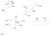
- Fig. 2 shows another embodiment of a monitoring system 100, where a first person 101 is monitored by a first position sensor 105.
- a second person, the protectee 102 wears a second position sensor 107, which helps the position monitor determine the position of the protectee 102 and setting the warning zone 103 and the exclusion zone 104.
- Fig. 2 two streets 108 and 109 are shown, which are schematically directed to the protectee 102. This means that the streets 108, 109 either directly or indirectly can bring the police patrol 112 and the ambulance 113 to the protectee 102. On the street 109 before the police patrol 112 there are two cars 110, 111, which in this case represent a traffic jam.
- Traffic data services which provide real time traffic data or information e.g. via data servers (see Fig. 3 ).
- Such services can be public services, e.g. provided by the authorities or private services provided e.g. by navigation system manufacturers.
- the position monitor and/or the modification unit (not explicitly shown in Fig. 2 ) know the position of the mobile support units 113, 112 and the position of the protectee 102, they can retrieve the relevant traffic information either from a public or private service and calculate a travel time for the mobile support units 113, 112 to the protectee 102.
- the position monitor and/or the modification unit determine the movement 106 of the first person 101 based on the signals of the first position sensor 105.
- the movement 106 can e.g. comprise a direction of movement and a speed of movement. Based on this information the position monitor and/or the modification unit can calculate a time of arrival for the first person 101 at the protectee 102.
- the position monitor and/or the modification unit can now set the size of the warning zone 103 and the size of the exclusion zone 104 such that the mobile support units 112, 113 will always arrive at the protectee 101 before the first person 101. For example, if the position monitor and/or the modification unit determine that the next police officer is 10 minutes away from the protectee 102, they will set the size of the exclusion zone such that the first person 101 will need a minimum of 10 minutes to arrive at the protectee 102. A certain safety margin can be added to the so determined size. With this configuration a disobey message will be dispatched to the police officer when the first person 101 enters the exclusion zone 104 and will give the police officer enough time to arrive at the protectee 102 before the first person 101.
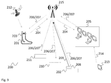
- FIG. 3 another monitoring system 200 is shown.
- the first position sensor 203 is GPS based and receives respective signals from satellite 212. Other types of position determination are also possible.
- the first position sensor 203 uses a cellular network 215, like a GSM network, to transmit data to position monitor 205.
- the position monitor 205 is a control room of the police, which can e.g. host a server running an application, which implements the position monitor 205 and/or the modification unit (not separately shown).
- the second person 202 or protectee 202 wears a second position sensor 208, which also uses the cellular network 215 to transmit its position to the position monitor 205 and/or modification unit.
- the position monitor 205 and/or the modification unit will use this information to observe if the first person 201 enters the warning zone or the exclusion zone (not explicitly shown in Fig. 3 ) and issue respective warning signals 206 or disobey signals 207.
- Two mobile support units 210, 211 use the cellular network 215 to receive the warning signals 206 or disobey signals 207. It is understood, that although not shown, the positions of the mobile support units 210, 211 can be transmitted to the control room 205 via the same cellular network or any other wireless data transmission.
- the position monitor 205 can e.g. retrieve traffic information 214 from a traffic server 213 and use this information to calculate the travel time for each of the mobile support units 210, 211 to the protectee 202. The position monitor 205 and/or the modification unit will then use this information to adequately set the size of the warning zone and/or the restriction zone.
- Fig. 4 shows a flow diagram of an embodiment of a method for monitoring a first person's position.
- the method starts with monitoring S1 the first person's position and provide a respective first position signal 7, 204.
- a second step S2 comprises monitoring S2 based on the first position signal 7, 204 if the first person 2, 101, 201 enters a spatially defined warning zone 4, 103 or a spatially defined exclusion zone 5, 104, which is a sub-zone of the warning zone 4, 103.
- a warning signal 9, 206 is provided S3 if the first person 2, 101, 201 enters the warning zone 4, 103 and a disobey signal 10, 207 is provided if the first person 2, 101, 201 enters the exclusion zone 5, 104.
- step S4 the warning zone 4, 103 and/or the exclusion zone 5, 104 are spatially modified S4 based on the distance 13 of at least one mobile support unit 11, 112, 113, 210, 211 from the warning zone 4, 103 and/or the exclusion zone 5, 104.
- Spatially modifying can e.g. comprises spatially increasing the warning zone 4, 103 and/or the exclusion zone 5, 104 if the mobile support units 11, 112, 113, 210, 211 are located at a distance 13 from the exclusion zone 5, 104, which is higher than a predetermined threshold value.
- spatially modifying may comprise retrieving traffic information 214 and calculating a travel time for the mobile support units 11, 112, 113, 210, 211 to the exclusion zone 5, 104. The size of the warning zone 4, 103 and/or the exclusion zone 5, 104 can then be modified based on the calculated travel time.
- Monitoring the first person's position can comprise determining the direction of movement and speed of movement of the first person 2, 101, 201. If this information is known spatially, modifying can comprise calculating the time of travel of the first person 2, 101, 201 to the center of the exclusion zone 5, 104 based on the determined direction of movement and speed of movement. The size of the warning zone 4, 103 and/or exclusion zone 5, 104 can then be adapted based on the travel time of the mobile support units 11, 112, 113, 210, 211 to the exclusion zone 5, 104 and the time of travel of the first person 2, 101, 201 to the center of the exclusion zone 5, 104.
- the center of the exclusion zone 5, 104 may be variable.
- the method can therefore comprise monitoring the position of the protectee 3, 102, 202 and setting the center of the exclusion zone 5, 104 to the position of the protectee 3, 102, 202.
- the first position and/or the second position can be determined wirelessly. Further, the first position and/or the second position can each be transmitted to a data server, especially on which monitoring, providing a warning signal 9, 206 and spatially modifying are performed.
- the present invention provides a monitoring system 1, 100, 200 for monitoring a first person's position.
- the monitoring system 1, 100, 200 comprises a first position sensor 6, 105, 203 configured to monitor the first person's position and provide a respective first position signal 7, 204.
- the monitoring system 1, 100, 200 comprises a position monitor 8, 205 configured to monitor based on the first position signal 7, 204 if the first person 2, 101, 201 enters a spatially defined warning zone 4, 103 or a spatially defined exclusion zone 5, 104, which is a sub-zone of the warning zone 4, 103.
- the position monitor 8, 205 is configured to provide a warning signal 9, 206 if the first person 2, 101, 201 enters the warning zone 4, 103 and provide a disobey signal 10, 207 if the first person 2, 101, 201 enters the exclusion zone 5, 104.
- the monitoring system 1, 100, 200 comprises a modification unit 12, which is configured to spatially modify the warning zone 4, 103 and/or the exclusion zone 5, 104 based on the distance 13 of at least one mobile support unit 11, 112, 113, 210, 211 from the warning zone 4, 103 and/or the exclusion zone 5, 104.
- the present invention further provides a corresponding method.
Landscapes
- Business, Economics & Management (AREA)
- Emergency Management (AREA)
- Physics & Mathematics (AREA)
- General Physics & Mathematics (AREA)
- Alarm Systems (AREA)
- Measurement Of Velocity Or Position Using Acoustic Or Ultrasonic Waves (AREA)
Abstract
Description
- The invention relates to a monitoring system for monitoring a first person's position and a corresponding method.
- Although applicable to any system that needs to track a person's position the present invention will mainly be described in conjunction with so called ankle monitors, also known as tether or ankle bracelet. Such ankle monitors are homing devices, which can e.g. be used to monitor a position of a person, when the ankle monitor is worn by the person, e.g. on the ankle.
- Ankle monitors usually comprise a position sensor, like e.g. a GPS-sensor, to determine the person's position. As such, ankle monitors can be used at least in two configurations. In a first configuration, a zone is defined, which the person may not leave. As soon as the person leaves the defined zone an alarm is sent e.g. to the next police patrol.
- In a second configuration, the ankle monitor can be used to monitor that the person does not enter a predefined spatial zone. This configuration can e.g. be used to protect stalker victims from the stalker, e.g. after a court has issued a restraining order or protective order.
- In order to use an ankle monitor in the second configuration the areas have to be defined which the monitored person may and must not enter.
- Document
US 8,493,219 B2 discloses a method for initially defining such areas by monitoring the person's movement paths during a learning period and then set the respective areas based on the monitored paths. However, this scheme provides little flexibility. - Accordingly, there is a need for an improved position monitoring for offenders.
- The present invention provides a monitoring system with the features of claim 1 and a monitoring method with the features of claim 7.
- The monitoring system for monitoring a first person's position comprises a first position sensor configured to monitor the first person's position and provide a respective first position signal. The monitoring system further comprises a position monitor configured to monitor based on the first position signal if the first person enters a spatially defined warning zone or a spatially defined exclusion zone, which is a sub-zone of the warning zone. The position monitor is configured to provide a warning signal if the first person enters the warning zone and provide a disobey signal if the first person enters the exclusion zone. Finally, the monitoring system further comprises a modification unit, which is configured to spatially modify the warning zone and/or the exclusion zone based on the distance of at least one mobile support unit, like e.g. a police officer, a police patrol, other security personnel, or e.g. an ambulance, from the warning zone and/or the exclusion zone.
- The monitoring method for monitoring a first person's position comprises the steps of monitoring the first person's position and provide a respective first position signal, and monitoring based on the first position signal if the first person enters a spatially defined warning zone or a spatially defined exclusion zone, which is a sub-zone of the warning zone. The method further comprises providing a warning signal if the first person enters the warning zone and provide a disobey signal if the first person enters the exclusion zone, and spatially modifying the warning zone and/or the exclusion zone based on the distance of at least one mobile support unit from the warning zone and/or the exclusion zone.
- The monitoring system can be used e.g. to monitor a person that for certain reasons may not enter a specific area or zone. Such a person can e.g. be an offender who may not approach his former victim up to more than a certain distance. It is understood that the term zone refers to a geographic or spatial area or zone. Such zones can be defined e.g. in a component of the monitoring system, e.g. the position monitor. For example, geographic coordinates can be stored in the position monitor, which define the zones. A further possibility is to store a center of a zone as a geographic coordinate and a corresponding radius.
- The first position sensor and/or the position monitor can e.g. be provided in an ankle monitor, tether or ankle bracelet. It is also possible to integrate the modification unit in the ankle monitor, tether or ankle bracelet. Alternatively, some or all of these components can also be implemented in other devices, like e.g. a mobile phone or another unit, which can be carried by the first person or fixed to the first person's body. Alternatively only the first position sensor can be provided in the ankle monitor and the position monitor and the modification unit can e.g. be provided in a server or a control room.
- A violation of the exclusion zone by the first person is signaled by the position monitor via the disobey signal. The disobey signal, when received e.g. by security personnel, requires immediate action e.g. by the police, because the disobey signal indicates that the first person violated the imposed stipulations.
- It is beneficial to provide the first person and eventually security units, like e.g. police officers, ambulances or the like, or a person or object, which is protected by the exclusion zone, with a warning prior to the disobey signal. Therefore, the present invention provides another zone, the so-called warning zone. The warning zone will usually be spatially larger than the exclusion zone and comprise the exclusion zone, i.e. the exclusion zone is a subset of the warning zone. If the first person enters the warning zone, the position monitor generates the warning signal. The warning signal indicates to the first person that he/she is progressing towards the exclusion zone. The warning signal can e.g. be provided to the mobile support units as well as the first person and gives the first person the chance to turn away from the exclusion zone.
- The present invention uses the finding that it is difficult to define fixed areas or zones as the warning zone and the exclusion zone, which may excessively limit the first person's freedom of movement, especially e.g. in small cities or villages. On the other hand, defining a very small warning zone and a very small exclusion zone may put the person or object to be protected in risk.
- The present invention therefore provides adaptive zones, i.e. the size of the warning zone and the exclusion zone are adaptively varied according to a position of a mobile support unit to the warning zone and/or the exclusion zone, i.e. the person or object to be protected.
- It is understood, that at least some of the components of the monitoring system can be provided in a computer or processor, e.g. as functions or computer programs.
- Further, any type of position sensor, e.g. a GPS sensor, can determine the position of the first person and the mobile support units. In addition, position sensors can be used, which are already present in the mobile support units. For example, police cars, ambulances and single police officers may already carry GPS sensors and their positions may therefore be known.
- The size of the warning zone and the exclusion zone may therefore vary such that the mobile support unit will reach the exclusion zone in time before the first person can deal any damage. The present invention therefore allows providing the first person with the maximum freedom, while increasing the safety of the protectee.
- Further embodiments of the present invention are subject of the further subclaims and of the following description, referring to the drawings.
- In one embodiment, the modification unit can be configured to spatially increase the warning zone and/or the exclusion zone if the mobile support units are located at a distance from the exclusion zone, which is higher than a predetermined threshold value. The predetermined threshold value can e.g. define a distance, where it is safe to suppose that the support unit will reach the exclusion zone in time to apprehend the first person for violating the exclusion zone, before the first person reaches the center of the exclusion zone, i.e. the person or object to be protected. The amount of increase of the sizes of the warning zone and/or the exclusion zone can be linearly related to the distance of the support unit. If e.g. the predetermined threshold value is 1 km and the mobile support unit is 2km away from the exclusion zone, the size of the warning zone can e.g. be calculated as 2km/1km * (minimum size). An analogous scheme can be applied for the exclusion zone. Further, maximum sizes can be provided for the warning zone and/or the exclusion zone. As an alternative a table may be provided, which provides specific sizes of the warning zone and/or the exclusion zone for specific distances of the mobile support units.
- In one embodiment, the modification unit can be configured to retrieve traffic information and calculate a travel time for the mobile support units to the exclusion zone. Further, the modification unit can be configured to modify the size of the warning zone and/or the exclusion zone based on the calculated travel time. In one example, a mean speed of movement can be assumed for the first person. The sizes of the warning zone and/or the exclusion zone can be adapted such that the mobile support units will reach the exclusion zone or it's center in the travel time and at the same time as the first person if he/she approaches the exclusion zone. If for example the modification unit calculates that a police patrol is 5 minutes away from the center of the exclusion zone. The speed of movement of the first person may be assumed to be 5km/h (1,39m/s). The first person will therefore cover a distance of about 1,39m/s*300s=417m in five minutes. This means that the radius of the warning zone may be set to about 417m. Further, in general an additional security margin of e.g. +5% - +10%, may be added to the determined size. In this case, the mobile support unit must move towards the center of the exclusion zone as soon as the warning signal is provided. As an alternative, the radius of the exclusion zone can be set to the calculated value and the size of the warning zone may be the size of the exclusion zone multiplied by a given fixed or variable factor. The factor may e.g. increase with increasing size of the exclusion zone. This will always provide the mobile support unit with enough time to arrive at the center of the exclusion zone before the first person. The necessary traffic information can e.g. be retrieved from publically available data sources via the internet. For example, certain navigation system publishers also provide real time traffic information via their services, which can be retrieved via public APIs, such as via a google maps API. Such information can also be retrieved from official databases, as e.g. police operated databases or databases of traffic institutes. Calculating the travel time can e.g. simply comprise a route calculation, online or offline.
- In one embodiment, the first position sensor can be configured to determine the direction of movement and speed of movement of the first person. Further, the modification unit can be configured to calculate the time of travel of the first person to the center of the exclusion zone based on the determined direction of movement and speed of movement. Finally, the modification unit can be configured to adapt the size of the warning zone and/or exclusion zone based on the travel time of the mobile support units to the exclusion zone and the time of travel of the first person to the center of the exclusion zone. The size of the exclusion zone can e.g. be set such that a mobile support unit will reach the center of the exclusion zone before the first person, if the mobile support unit initiates movement as soon as the disobey signal is received. If for example a police patrol is 5 minutes away from the center of the exclusion zone, the size of the exclusion zone will be set such that the first person will need 5 minutes to arrive at the center of the exclusion zone with the determined speed.
- In one embodiment, the monitoring system can comprise a second position sensor configured to monitor the position of a protectee, e.g. a person or an object, wherein the modification unit is configured to set the center of the exclusion zone to the position of the protectee. Monitoring the position of a protectee allows automatically following the protectee with the warning zone and the exclusion zone. This provides full freedom of movement to the protectee and at the same time maximum security.
- In one embodiment, the first position sensor and/or the second position sensor can comprise wireless position sensors, as e.g. GPS sensors, Cell Phone based position sensors, Bluetooth based position sensor, like iBeacons. Further, the first position sensor and/or the second position sensor can each comprise a communication interface, e.g. a GSM interface, UMTS interface, LTE interface, WIFI interface or the like, and can be configured provide the position information to a data server. The data server may e.g. be accessible via the internet and may comprise the modification unit. This allows centrally fusing the data of the position sensors as well as the position information of the support units and centrally performing all necessary calculations. The data server may e.g. be a police operated server, which may also be coupled with a police control room. In another embodiment, the position sensors may use e.g. a smartphone as data gateway. The position sensors can e.g. be coupled to the smartphone via Bluetooth and use a so-called tethering function of the smartphone.
- For a more complete understanding of the present invention and advantages thereof, reference is now made to the following description taken in conjunction with the accompanying drawings. The invention is explained in more detail below using exemplary embodiments, which are specified in the schematic figures of the drawings, in which:
- Fig. 1
- shows a block diagram of an embodiment of a monitoring system according to the present patent application;
- Fig. 2
- shows a block diagram of another embodiment of a monitoring system according to the present patent application;
- Fig. 3
- shows a block diagram of another embodiment of a monitoring system according to the present patent application; and
- Fig. 4
- shows a flow diagram of an embodiment of a method according to the present patent application.
- In the figures like reference signs denote like elements unless stated otherwise.
-
Fig. 1 shows a schematic block diagram of the monitoring system 1. The monitoring system 1 monitors afirst person 2 in order to protect a protectee 3. The first person 1 might e.g. be an offender under a restraining order or protective order, while the protectee 3 might be his former victim. - An
exclusion zone 5 defines a circle-shaped area, which thefirst person 2 may not enter. Further, warning zone 4 defines a circle-shaped area, which includes theexclusion zone 5. InFig. 1 theexclusion zone 5 and the warning zone 4 have the same center point and the radius of the warning zone 4 is larger than the radius of theexclusion zone 5. - The warning zone 4 serves to generate an advance warning, if the
first person 2 advances the protectee 3. On the one hand, this serves to give thefirst person 2 the chance to turn away from the protectee 3, e.g. if thefirst person 2 advanced the protectee 3 accidentally. On the other hand, such an advance warning can also alert the protectee 3 and anymobile support units 11, like e.g. police officers. - A first position sensor 6 monitors the position of the
first person 2. The first position sensor 6 is a GPS-based position sensor 6. The first position sensor 6 may also use other information to identify the current position of thefirst person 2. The first position sensor 6 may e.g. also use cell phone signals, iBeacons or the like. - The first position sensor 6 then wirelessly transmits the position of the
first person 2 in a first position signal 7 to theposition monitor 8. The position monitor 8 may e.g. be located in a police control room and comprise detailed information about the warning zone 4 and theexclusion zone 5. InFig. 1 the protectee 3 doesn't have a position monitor and the warning zone 4 and theexclusion zone 5 may e.g. be located at a fixed position, like e.g. the protectee's house or the protectee 3 may be an immobile object. As a matter of course, the protectee 3 may also ware a position sensor (seeFigs. 2 and3 ). In such a case the position monitor 8 will move the warning zone 4 and theexclusion zone 5 with the protectee 3 such that the protectee 3 is the center point of the warning zone 4 and theexclusion zone 5. - The position monitor 8 will not only keep track of the warning zone 4 and the
exclusion zone 5. In Addition, the position monitor 8 will also monitor if thefirst person 2 enters the warning zone 4 or theexclusion zone 5. If the position monitor 8 detects that thefirst person 2 enters the warning zone 4, the position monitor 8 generates a warning signal 9, which it transmits tomobile support units 11, like police officers or ambulances, near the protectee 3. Even if it is not displayed inFig. 1 the position monitor 8 can provide the warning signal 9 to thefirst person 2, e.g. wirelessly via a cell phone network or the like. This will allow thefirst person 2 to turn around and leave the warning zone 4. In addition, the position monitor 8 can also provide the warning signal 9 to the protectee. If thefirst person 2 will not turn around and enter theexclusion zone 5, the position monitor 8 will issue the disobey command 10, which signals the violation of theexclusion zone 5, to themobile support units 11. As with the warning signal 9 the disobey signal 10 can also be provided to thefirst person 2 and/or the protectee 3. - The position monitor 8 not only monitors the position of the
second person 2 and the protectee 3. In addition the position monitor 8 also retrieves information about the positions of the mobile support units 11 (although only one is shown, more are hinted at by three dots) and calculates thedistance 13 of themobile support units 11 to the protectee 3. This information can either be directly provided by dedicated position sensors on themobile support units 11, e.g. via a cell phone network, or via a central database, like e.g. a police server. - If the
first person 2 should actually try to reach the protectee 3, it is crucial to provide themobile support units 11 with enough time to reach the protectee 3 before thefirst person 2 does. Therefore, the position monitor 8 can provide the information about thedistance 13 to themodification unit 12. Themodification unit 12 will use this information to adapt the sizes of the warning zone 4 and theexclusion zone 5, themodifications 14 indicated inFig. 1 by dashed lines. Adapting the size of the warning zone 4 and/or theexclusion zone 5 refers e.g. to adapting respective geographic coordinates or a center point coordinate and a radius in a memory of theposition monitor 8. Any other form of storing and managing the warning zone 4 and/or theexclusion zone 5 can be used. - In one embodiment, the
modification unit 12 comprises minimum sizes for the warning zone 4 and theexclusion zone 5. Themodification unit 12 will not modify the warning zone 4 and theexclusion zone 5 to be smaller than these minimum sizes in any case. However, if thedistance 13 is larger than a predefined threshold value, themodification unit 12 will increase the size, e.g. the radius of the warning zone 4 and theexclusion zone 5. The increase factor can e.g. be linearly calculated based on thedistance 13 and the threshold value. The threshold value can e.g. be 1 km. The increase factor can e.g. be thedistance 13 divided by the threshold value. If for example themobile support unit 11 were 3km away from the protectee 3, the increase factor would be 3. In this case, themodification unit 12 would modify the warning zone 4 and theexclusion zone 5 to be three times the minimum size. Another possible formula would be e.g. (increase factor) = (distance 13)/(threshold) * factor, wherein the factor can e.g. be any value between 0,01 and 10. A maximum limit can also be defined for the sizes of the warning zone 4 and theexclusion zone 5. - The position monitor 8 and/or the
modification unit 12 can also adapt the sizes of the warning zone 4 and theexclusion zone 5 according to a time of arrival of themobile support units 11 at the protectee 3. The position monitor 8 and/or themodification unit 12 may e.g. assume a certain speed of movement for themobile support units 11, e.g. based on the type ofmobile support unit 11, e.g. "walking officer", "police vehicle", ambulance". This information about the type ofmobile support unit 11 or a value of the mean speed of movement can be provided by themobile support unit 11 or via the data server already mentioned above. The position monitor 8 and/or themodification unit 12 will then set the size of the warning zone 4 and theexclusion zone 5 such that at least one of themobile support units 11 will arrive at the protectee 3 before thefirst person 2 does. A mean speed of thefirst person 2 can also be assumed. As an alternative, the speed of thefirst person 2 can be determined based on the position signal 7. -
Fig. 2 shows another embodiment of amonitoring system 100, where afirst person 101 is monitored by afirst position sensor 105. A second person, theprotectee 102, wears asecond position sensor 107, which helps the position monitor determine the position of theprotectee 102 and setting thewarning zone 103 and theexclusion zone 104. - In
Fig. 2 twostreets protectee 102. This means that thestreets ambulance 113 to theprotectee 102. On thestreet 109 before the police patrol 112 there are twocars - Today a plurality of traffic data services exist, which provide real time traffic data or information e.g. via data servers (see
Fig. 3 ). Such services can be public services, e.g. provided by the authorities or private services provided e.g. by navigation system manufacturers. - Because the position monitor and/or the modification unit (not explicitly shown in
Fig. 2 ) know the position of themobile support units 113, 112 and the position of theprotectee 102, they can retrieve the relevant traffic information either from a public or private service and calculate a travel time for themobile support units 113, 112 to theprotectee 102. - Further, the position monitor and/or the modification unit determine the
movement 106 of thefirst person 101 based on the signals of thefirst position sensor 105. Themovement 106 can e.g. comprise a direction of movement and a speed of movement. Based on this information the position monitor and/or the modification unit can calculate a time of arrival for thefirst person 101 at theprotectee 102. - The position monitor and/or the modification unit can now set the size of the
warning zone 103 and the size of theexclusion zone 104 such that themobile support units 112, 113 will always arrive at theprotectee 101 before thefirst person 101. For example, if the position monitor and/or the modification unit determine that the next police officer is 10 minutes away from theprotectee 102, they will set the size of the exclusion zone such that thefirst person 101 will need a minimum of 10 minutes to arrive at theprotectee 102. A certain safety margin can be added to the so determined size. With this configuration a disobey message will be dispatched to the police officer when thefirst person 101 enters theexclusion zone 104 and will give the police officer enough time to arrive at theprotectee 102 before thefirst person 101. - In
Fig. 3 anothermonitoring system 200 is shown. InFig. 3 only the ankle of thefirst person 201 is shown wearing thefirst position sensor 203. Thefirst position sensor 203 is GPS based and receives respective signals fromsatellite 212. Other types of position determination are also possible. Thefirst position sensor 203 uses acellular network 215, like a GSM network, to transmit data to position monitor 205. InFig. 3 the position monitor 205 is a control room of the police, which can e.g. host a server running an application, which implements the position monitor 205 and/or the modification unit (not separately shown). Further, thesecond person 202 orprotectee 202 wears asecond position sensor 208, which also uses thecellular network 215 to transmit its position to the position monitor 205 and/or modification unit. - The position monitor 205 and/or the modification unit will use this information to observe if the
first person 201 enters the warning zone or the exclusion zone (not explicitly shown inFig. 3 ) and issue respective warning signals 206 or disobey signals 207. - Two
mobile support units cellular network 215 to receive the warning signals 206 or disobey signals 207. It is understood, that although not shown, the positions of themobile support units control room 205 via the same cellular network or any other wireless data transmission. - As already explained above, the position monitor 205 can e.g. retrieve
traffic information 214 from atraffic server 213 and use this information to calculate the travel time for each of themobile support units protectee 202. The position monitor 205 and/or the modification unit will then use this information to adequately set the size of the warning zone and/or the restriction zone. -
Fig. 4 shows a flow diagram of an embodiment of a method for monitoring a first person's position. The method starts with monitoring S1 the first person's position and provide a respectivefirst position signal 7, 204. A second step S2 comprises monitoring S2 based on thefirst position signal 7, 204 if thefirst person warning zone 4, 103 or a spatially definedexclusion zone warning zone 4, 103. A warning signal 9, 206 is provided S3 if thefirst person warning zone 4, 103 and a disobey signal 10, 207 is provided if thefirst person exclusion zone warning zone 4, 103 and/or theexclusion zone distance 13 of at least onemobile support unit warning zone 4, 103 and/or theexclusion zone - Spatially modifying can e.g. comprises spatially increasing the
warning zone 4, 103 and/or theexclusion zone mobile support units distance 13 from theexclusion zone traffic information 214 and calculating a travel time for themobile support units exclusion zone warning zone 4, 103 and/or theexclusion zone - Monitoring the first person's position can comprise determining the direction of movement and speed of movement of the
first person first person exclusion zone warning zone 4, 103 and/orexclusion zone mobile support units exclusion zone first person exclusion zone - The center of the
exclusion zone protectee exclusion zone protectee - Although specific embodiments have been illustrated and described herein, it will be appreciated by those of ordinary skill in the art that a variety of alternate and/or equivalent implementations exist. It should be appreciated that the exemplary embodiment or exemplary embodiments are only examples, and are not intended to limit the scope, applicability, or configuration in any way. Rather, the foregoing summary and detailed description will provide those skilled in the art with a convenient road map for implementing at least one exemplary embodiment, it being understood that various changes may be made in the function and arrangement of elements described in an exemplary embodiment without departing from the scope as set forth in the appended claims and their legal equivalents. Generally, this application is intended to cover any adaptations or variations of the specific embodiments discussed herein.
- The present invention provides a
monitoring system monitoring system first position sensor first position signal 7, 204. Further, themonitoring system position monitor first position signal 7, 204 if thefirst person warning zone 4, 103 or a spatially definedexclusion zone warning zone 4, 103. The position monitor 8, 205 is configured to provide a warning signal 9, 206 if thefirst person warning zone 4, 103 and provide a disobey signal 10, 207 if thefirst person exclusion zone monitoring system modification unit 12, which is configured to spatially modify thewarning zone 4, 103 and/or theexclusion zone distance 13 of at least onemobile support unit warning zone 4, 103 and/or theexclusion zone -
- 1, 100, 200
- monitoring system
- 2, 101, 201
- first person
- 3, 102, 202
- protectee
- 4, 103
- warning zone
- 5, 104
- exclusion zone
- 6, 105, 203
- first position sensor
- 7, 204
- first position signal
- 8, 205
- position monitor
- 9, 206
- warning signal
- 10, 207
- disobey signal
- 11, 112, 113, 210, 211
- mobile support unit
- 12
- modification unit
- 13
- distance
- 14
- modification
- 106
- movement
- 107, 208
- second position sensor
- 209
- second position signal
- 108, 109
- streets
- 110, 111
- vehicles
- 114, 115
- size variation
- 212
- satellite
- 213
- traffic server
- 214
- traffic information
- 215
- cellular network
- S1 - S4
- method steps
Claims (12)
- Monitoring system (1, 100, 200) for monitoring a first person's position, the system comprising:a first position sensor (6, 105, 203) configured to monitor the first person's position and provide a respective first position signal (7, 204),a position monitor (8, 205) configured to monitor based on the first position signal (7, 204) if the first person (2, 101, 201) enters a spatially defined warning zone (4, 103) or a spatially defined exclusion zone (5, 104), which is a sub-zone of the warning zone (4, 103), wherein the position monitor (8, 205) is configured to provide a warning signal (9, 206) if the first person (2, 101, 201) enters the warning zone (4, 103) and provide a disobey signal (10, 207) if the first person (2, 101, 201) enters the exclusion zone (5, 104), anda modification unit (12), which is configured to spatially modify the warning zone (4, 103) and/or the exclusion zone (5, 104) based on the distance (13) of at least one mobile support unit (11, 112, 113, 210, 211) from the warning zone (4, 103) and/or the exclusion zone (5, 104).
- Monitoring system (1, 100, 200) according to claim 1, wherein the modification unit (12) is configured to spatially increase the warning zone (4, 103) and/or the exclusion zone (5, 104) if the mobile support units (11, 112, 113, 210, 211) are located at a distance (13) from the exclusion zone (5, 104), which is higher than a predetermined threshold value.
- Monitoring system (1, 100, 200) according to any one of the preceding claims, wherein the modification unit (12) is configured to retrieve traffic information (214) and calculate a travel time for the mobile support units (11, 112, 113, 210, 211) to the exclusion zone (5, 104), and
wherein the modification unit (12) is configured to modify the size of the warning zone (4, 103) and/or the exclusion zone (5, 104) based on the calculated travel time. - Monitoring system (1, 100, 200) according to claim 3, wherein the first position sensor (6, 105, 203) is configured to determine the direction of movement and speed of movement of the first person (2, 101, 201), and
wherein the modification unit (12) is configured to calculate the time of travel of the first person (2, 101, 201) to the center of the exclusion zone (5, 104) based on the determined direction of movement and speed of movement, and
wherein the modification unit (12) is configured to adapt the size of the warning zone (4, 103) and/or exclusion zone (5, 104) based on the travel time of the mobile support units (11, 112, 113, 210, 211) to the exclusion zone (5, 104) and the time of travel of the first person (2, 101, 201) to the center of the exclusion zone (5, 104). - Monitoring system (1, 100, 200) according to any one of the preceding claims, comprising a second position sensor (107, 208) configured to monitor the position of a protectee (3, 102, 202), wherein the modification unit (12) is configured to set the center of the exclusion zone (5, 104) to the position of the protectee (3, 102, 202).
- Monitoring system (1, 100, 200) according any one of the preceding claims, wherein the first position sensor (6, 105, 203) and/or the second position sensor (107, 208) comprise wireless position sensors, and/or
wherein the first position sensor (6, 105, 203) and/or the second position sensor (107, 208) each comprise a communication interface, and are configured provide the position information to a data server. - Monitoring method for monitoring a first person's position, the method comprising the steps of:monitoring (S1) the first person's position and provide a respective first position signal (7, 204),monitoring (S2) based on the first position signal (7, 204) if the first person (2, 101, 201) enters a spatially defined warning zone (4, 103) or a spatially defined exclusion zone (5, 104), which is a sub-zone of the warning zone (4, 103),providing (S3) a warning signal (9, 206) if the first person (2, 101, 201) enters the warning zone (4, 103) and provide a disobey signal (10, 207) if the first person (2, 101, 201) enters the exclusion zone (5, 104), andspatially (S4) modifying the warning zone (4, 103) and/or the exclusion zone (5, 104) based on the distance (13) of at least one mobile support unit (11, 112, 113, 210, 211) from the warning zone (4, 103) and/or the exclusion zone (5, 104).
- Monitoring method according to claim 7, wherein spatially modify comprises spatially increasing the warning zone (4, 103) and/or the exclusion zone (5, 104) if the mobile support units (11, 112, 113, 210, 211) are located at a distance (13) from the exclusion zone (5, 104), which is higher than a predetermined threshold value.
- Monitoring method according to any one of the preceding claims 7 and 8, wherein spatially modifying comprises retrieving traffic information (214) and calculating a travel time for the mobile support units (11, 112, 113, 210, 211) to the exclusion zone (5, 104), and modifying the size of the warning zone (4, 103) and/or the exclusion zone (5, 104) based on the calculated travel time.
- Monitoring method according to claim 9, wherein monitoring the first person's position comprises determining the direction of movement and speed of movement of the first person (2, 101, 201), and
wherein spatially modifying comprises calculating the time of travel of the first person (2, 101, 201) to the center of the exclusion zone (5, 104) based on the determined direction of movement and speed of movement, and
adapting the size of the warning zone (4, 103) and/or exclusion zone (5, 104) based on the travel time of the mobile support units (11, 112, 113, 210, 211) to the exclusion zone (5, 104) and the time of travel of the first person (2, 101, 201) to the center of the exclusion zone (5, 104). - Monitoring method according to any one of the preceding claims 7 to 10, comprising monitoring the position of a protectee (3, 102, 202) and setting the center of the exclusion zone (5, 104) to the position of the protectee (3, 102, 202).
- Monitoring method according any one of the preceding claims 7 to 11, wherein the first position and/or the second position are determined wirelessly, and/or wherein the first position and/or the second position each are transmitted to a data server, especially wherein monitoring, providing a warning signal (9, 206) and spatially modifying are performed on the data server.
Priority Applications (3)
| Application Number | Priority Date | Filing Date | Title |
|---|---|---|---|
| TR2018/11236T TR201811236T4 (en) | 2016-05-06 | 2016-05-06 | Monitoring system and method. |
| EP16168550.8A EP3242279B1 (en) | 2016-05-06 | 2016-05-06 | Monitoring system and method |
| TR2017/02260A TR201702260A2 (en) | 2016-05-06 | 2017-02-15 | Monitoring system and method. |
Applications Claiming Priority (1)
| Application Number | Priority Date | Filing Date | Title |
|---|---|---|---|
| EP16168550.8A EP3242279B1 (en) | 2016-05-06 | 2016-05-06 | Monitoring system and method |
Publications (2)
| Publication Number | Publication Date |
|---|---|
| EP3242279A1 true EP3242279A1 (en) | 2017-11-08 |
| EP3242279B1 EP3242279B1 (en) | 2018-07-18 |
Family
ID=55919694
Family Applications (1)
| Application Number | Title | Priority Date | Filing Date |
|---|---|---|---|
| EP16168550.8A Active EP3242279B1 (en) | 2016-05-06 | 2016-05-06 | Monitoring system and method |
Country Status (2)
| Country | Link |
|---|---|
| EP (1) | EP3242279B1 (en) |
| TR (2) | TR201811236T4 (en) |
Citations (7)
| Publication number | Priority date | Publication date | Assignee | Title |
|---|---|---|---|---|
| US5461390A (en) * | 1994-05-27 | 1995-10-24 | At&T Ipm Corp. | Locator device useful for house arrest and stalker detection |
| US20110133937A1 (en) * | 2009-12-03 | 2011-06-09 | Bi Incorporated | Systems and Methods for Disrupting Criminal Activity |
| WO2013103782A1 (en) * | 2012-01-06 | 2013-07-11 | 3M Innovative Properties Company | Released offender geospatial location information trend analysis |
| WO2013103776A1 (en) * | 2012-01-06 | 2013-07-11 | 3M Innovative Properties Company | Released offender geospatial location information clearinghouse |
| US8493219B2 (en) | 2008-11-14 | 2013-07-23 | Bi Incorporated | Systems and methods for adaptive monitoring and tracking of a target having a learning period |
| US20150061864A1 (en) * | 2009-12-03 | 2015-03-05 | Bi Incorporated | Systems and Methods for Contact Avoidance |
| US20160110987A1 (en) * | 2014-10-21 | 2016-04-21 | Anytransactions, Inc. | Personal monitor and tracking system |
-
2016
- 2016-05-06 EP EP16168550.8A patent/EP3242279B1/en active Active
- 2016-05-06 TR TR2018/11236T patent/TR201811236T4/en unknown
-
2017
- 2017-02-15 TR TR2017/02260A patent/TR201702260A2/en unknown
Patent Citations (7)
| Publication number | Priority date | Publication date | Assignee | Title |
|---|---|---|---|---|
| US5461390A (en) * | 1994-05-27 | 1995-10-24 | At&T Ipm Corp. | Locator device useful for house arrest and stalker detection |
| US8493219B2 (en) | 2008-11-14 | 2013-07-23 | Bi Incorporated | Systems and methods for adaptive monitoring and tracking of a target having a learning period |
| US20110133937A1 (en) * | 2009-12-03 | 2011-06-09 | Bi Incorporated | Systems and Methods for Disrupting Criminal Activity |
| US20150061864A1 (en) * | 2009-12-03 | 2015-03-05 | Bi Incorporated | Systems and Methods for Contact Avoidance |
| WO2013103782A1 (en) * | 2012-01-06 | 2013-07-11 | 3M Innovative Properties Company | Released offender geospatial location information trend analysis |
| WO2013103776A1 (en) * | 2012-01-06 | 2013-07-11 | 3M Innovative Properties Company | Released offender geospatial location information clearinghouse |
| US20160110987A1 (en) * | 2014-10-21 | 2016-04-21 | Anytransactions, Inc. | Personal monitor and tracking system |
Also Published As
| Publication number | Publication date |
|---|---|
| TR201702260A2 (en) | 2017-11-21 |
| EP3242279B1 (en) | 2018-07-18 |
| TR201811236T4 (en) | 2018-08-27 |
Similar Documents
| Publication | Publication Date | Title |
|---|---|---|
| US20250140112A1 (en) | Systems and methods for alerting persons of approaching vehicles | |
| US11830366B2 (en) | Using geofences to restrict vehicle operation | |
| Anand et al. | Emergency traffic management for ambulance using wireless communication | |
| US9070290B2 (en) | Apparatus and system for monitoring and managing traffic flow | |
| US10431093B2 (en) | System and method for collision avoidance | |
| WO2011095974A1 (en) | Methods and systems of collision avoidance and/or alerting for users of mobile communication devices | |
| EP2659470B1 (en) | Real-time drive assistance method | |
| US11107302B2 (en) | Methods and systems for emergency event management | |
| US9668095B1 (en) | Systems and methods for supporting zones in a monitoring system | |
| Sumayya et al. | Vanet based vehicle tracking module for safe and efficient road transportation system | |
| CN104742860A (en) | Vehicle alarm method and vehicle alarm system | |
| KR101498931B1 (en) | Crime prevention monitoring method for electronic ankle bracelet wearers | |
| US8896441B2 (en) | System and method for tracking people | |
| AU2015238429B2 (en) | Navigation system and method | |
| KR20120125092A (en) | Person in charge matching system for prevent and transaction accident | |
| EP3242279B1 (en) | Monitoring system and method | |
| Aung et al. | Vehicle accident detection on highway and communication to the closest rescue service | |
| KR102890372B1 (en) | User protection and assistance system for dementia patients and the elderly using mobile beacons | |
| EP3807857A1 (en) | A road tunnel security system | |
| CN108305486A (en) | A kind of state of an illness processing path planing method of first-aid system | |
| KR20030022613A (en) | System for preventing occurrence of a missing child | |
| JP6541767B1 (en) | Vehicle movement adjustment device, vehicle movement adjustment method and program | |
| Aung et al. | Location tracking of accident detection on expressway for informing nearest rescue service | |
| WO2020162861A2 (en) | Smart road application | |
| EP2991006A1 (en) | Method for providing local risk level information |
Legal Events
| Date | Code | Title | Description |
|---|---|---|---|
| PUAI | Public reference made under article 153(3) epc to a published international application that has entered the european phase |
Free format text: ORIGINAL CODE: 0009012 |
|
| STAA | Information on the status of an ep patent application or granted ep patent |
Free format text: STATUS: REQUEST FOR EXAMINATION WAS MADE |
|
| 17P | Request for examination filed |
Effective date: 20170317 |
|
| AK | Designated contracting states |
Kind code of ref document: A1 Designated state(s): AL AT BE BG CH CY CZ DE DK EE ES FI FR GB GR HR HU IE IS IT LI LT LU LV MC MK MT NL NO PL PT RO RS SE SI SK SM TR |
|
| AX | Request for extension of the european patent |
Extension state: BA ME |
|
| GRAP | Despatch of communication of intention to grant a patent |
Free format text: ORIGINAL CODE: EPIDOSNIGR1 |
|
| STAA | Information on the status of an ep patent application or granted ep patent |
Free format text: STATUS: GRANT OF PATENT IS INTENDED |
|
| INTG | Intention to grant announced |
Effective date: 20180118 |
|
| GRAS | Grant fee paid |
Free format text: ORIGINAL CODE: EPIDOSNIGR3 |
|
| GRAA | (expected) grant |
Free format text: ORIGINAL CODE: 0009210 |
|
| STAA | Information on the status of an ep patent application or granted ep patent |
Free format text: STATUS: THE PATENT HAS BEEN GRANTED |
|
| AK | Designated contracting states |
Kind code of ref document: B1 Designated state(s): AL AT BE BG CH CY CZ DE DK EE ES FI FR GB GR HR HU IE IS IT LI LT LU LV MC MK MT NL NO PL PT RO RS SE SI SK SM TR |
|
| REG | Reference to a national code |
Ref country code: GB Ref legal event code: FG4D |
|
| REG | Reference to a national code |
Ref country code: CH Ref legal event code: EP |
|
| REG | Reference to a national code |
Ref country code: IE Ref legal event code: FG4D |
|
| REG | Reference to a national code |
Ref country code: AT Ref legal event code: REF Ref document number: 1020182 Country of ref document: AT Kind code of ref document: T Effective date: 20180815 |
|
| REG | Reference to a national code |
Ref country code: DE Ref legal event code: R096 Ref document number: 602016004064 Country of ref document: DE |
|
| REG | Reference to a national code |
Ref country code: NL Ref legal event code: MP Effective date: 20180718 |
|
| REG | Reference to a national code |
Ref country code: LT Ref legal event code: MG4D |
|
| REG | Reference to a national code |
Ref country code: AT Ref legal event code: MK05 Ref document number: 1020182 Country of ref document: AT Kind code of ref document: T Effective date: 20180718 |
|
| PG25 | Lapsed in a contracting state [announced via postgrant information from national office to epo] |
Ref country code: NL Free format text: LAPSE BECAUSE OF FAILURE TO SUBMIT A TRANSLATION OF THE DESCRIPTION OR TO PAY THE FEE WITHIN THE PRESCRIBED TIME-LIMIT Effective date: 20180718 |
|
| PG25 | Lapsed in a contracting state [announced via postgrant information from national office to epo] |
Ref country code: NO Free format text: LAPSE BECAUSE OF FAILURE TO SUBMIT A TRANSLATION OF THE DESCRIPTION OR TO PAY THE FEE WITHIN THE PRESCRIBED TIME-LIMIT Effective date: 20181018 Ref country code: GR Free format text: LAPSE BECAUSE OF FAILURE TO SUBMIT A TRANSLATION OF THE DESCRIPTION OR TO PAY THE FEE WITHIN THE PRESCRIBED TIME-LIMIT Effective date: 20181019 Ref country code: AT Free format text: LAPSE BECAUSE OF FAILURE TO SUBMIT A TRANSLATION OF THE DESCRIPTION OR TO PAY THE FEE WITHIN THE PRESCRIBED TIME-LIMIT Effective date: 20180718 Ref country code: LT Free format text: LAPSE BECAUSE OF FAILURE TO SUBMIT A TRANSLATION OF THE DESCRIPTION OR TO PAY THE FEE WITHIN THE PRESCRIBED TIME-LIMIT Effective date: 20180718 Ref country code: BG Free format text: LAPSE BECAUSE OF FAILURE TO SUBMIT A TRANSLATION OF THE DESCRIPTION OR TO PAY THE FEE WITHIN THE PRESCRIBED TIME-LIMIT Effective date: 20181018 Ref country code: PL Free format text: LAPSE BECAUSE OF FAILURE TO SUBMIT A TRANSLATION OF THE DESCRIPTION OR TO PAY THE FEE WITHIN THE PRESCRIBED TIME-LIMIT Effective date: 20180718 Ref country code: IS Free format text: LAPSE BECAUSE OF FAILURE TO SUBMIT A TRANSLATION OF THE DESCRIPTION OR TO PAY THE FEE WITHIN THE PRESCRIBED TIME-LIMIT Effective date: 20181118 Ref country code: SE Free format text: LAPSE BECAUSE OF FAILURE TO SUBMIT A TRANSLATION OF THE DESCRIPTION OR TO PAY THE FEE WITHIN THE PRESCRIBED TIME-LIMIT Effective date: 20180718 Ref country code: RS Free format text: LAPSE BECAUSE OF FAILURE TO SUBMIT A TRANSLATION OF THE DESCRIPTION OR TO PAY THE FEE WITHIN THE PRESCRIBED TIME-LIMIT Effective date: 20180718 Ref country code: FI Free format text: LAPSE BECAUSE OF FAILURE TO SUBMIT A TRANSLATION OF THE DESCRIPTION OR TO PAY THE FEE WITHIN THE PRESCRIBED TIME-LIMIT Effective date: 20180718 |
|
| PG25 | Lapsed in a contracting state [announced via postgrant information from national office to epo] |
Ref country code: AL Free format text: LAPSE BECAUSE OF FAILURE TO SUBMIT A TRANSLATION OF THE DESCRIPTION OR TO PAY THE FEE WITHIN THE PRESCRIBED TIME-LIMIT Effective date: 20180718 Ref country code: LV Free format text: LAPSE BECAUSE OF FAILURE TO SUBMIT A TRANSLATION OF THE DESCRIPTION OR TO PAY THE FEE WITHIN THE PRESCRIBED TIME-LIMIT Effective date: 20180718 Ref country code: HR Free format text: LAPSE BECAUSE OF FAILURE TO SUBMIT A TRANSLATION OF THE DESCRIPTION OR TO PAY THE FEE WITHIN THE PRESCRIBED TIME-LIMIT Effective date: 20180718 |
|
| REG | Reference to a national code |
Ref country code: DE Ref legal event code: R097 Ref document number: 602016004064 Country of ref document: DE |
|
| PG25 | Lapsed in a contracting state [announced via postgrant information from national office to epo] |
Ref country code: EE Free format text: LAPSE BECAUSE OF FAILURE TO SUBMIT A TRANSLATION OF THE DESCRIPTION OR TO PAY THE FEE WITHIN THE PRESCRIBED TIME-LIMIT Effective date: 20180718 Ref country code: IT Free format text: LAPSE BECAUSE OF FAILURE TO SUBMIT A TRANSLATION OF THE DESCRIPTION OR TO PAY THE FEE WITHIN THE PRESCRIBED TIME-LIMIT Effective date: 20180718 Ref country code: ES Free format text: LAPSE BECAUSE OF FAILURE TO SUBMIT A TRANSLATION OF THE DESCRIPTION OR TO PAY THE FEE WITHIN THE PRESCRIBED TIME-LIMIT Effective date: 20180718 Ref country code: RO Free format text: LAPSE BECAUSE OF FAILURE TO SUBMIT A TRANSLATION OF THE DESCRIPTION OR TO PAY THE FEE WITHIN THE PRESCRIBED TIME-LIMIT Effective date: 20180718 Ref country code: CZ Free format text: LAPSE BECAUSE OF FAILURE TO SUBMIT A TRANSLATION OF THE DESCRIPTION OR TO PAY THE FEE WITHIN THE PRESCRIBED TIME-LIMIT Effective date: 20180718 |
|
| PLBE | No opposition filed within time limit |
Free format text: ORIGINAL CODE: 0009261 |
|
| STAA | Information on the status of an ep patent application or granted ep patent |
Free format text: STATUS: NO OPPOSITION FILED WITHIN TIME LIMIT |
|
| PG25 | Lapsed in a contracting state [announced via postgrant information from national office to epo] |
Ref country code: SK Free format text: LAPSE BECAUSE OF FAILURE TO SUBMIT A TRANSLATION OF THE DESCRIPTION OR TO PAY THE FEE WITHIN THE PRESCRIBED TIME-LIMIT Effective date: 20180718 Ref country code: SM Free format text: LAPSE BECAUSE OF FAILURE TO SUBMIT A TRANSLATION OF THE DESCRIPTION OR TO PAY THE FEE WITHIN THE PRESCRIBED TIME-LIMIT Effective date: 20180718 Ref country code: DK Free format text: LAPSE BECAUSE OF FAILURE TO SUBMIT A TRANSLATION OF THE DESCRIPTION OR TO PAY THE FEE WITHIN THE PRESCRIBED TIME-LIMIT Effective date: 20180718 |
|
| 26N | No opposition filed |
Effective date: 20190423 |
|
| PG25 | Lapsed in a contracting state [announced via postgrant information from national office to epo] |
Ref country code: SI Free format text: LAPSE BECAUSE OF FAILURE TO SUBMIT A TRANSLATION OF THE DESCRIPTION OR TO PAY THE FEE WITHIN THE PRESCRIBED TIME-LIMIT Effective date: 20180718 |
|
| REG | Reference to a national code |
Ref country code: CH Ref legal event code: PL |
|
| PG25 | Lapsed in a contracting state [announced via postgrant information from national office to epo] |
Ref country code: MC Free format text: LAPSE BECAUSE OF FAILURE TO SUBMIT A TRANSLATION OF THE DESCRIPTION OR TO PAY THE FEE WITHIN THE PRESCRIBED TIME-LIMIT Effective date: 20180718 Ref country code: LI Free format text: LAPSE BECAUSE OF NON-PAYMENT OF DUE FEES Effective date: 20190531 Ref country code: CH Free format text: LAPSE BECAUSE OF NON-PAYMENT OF DUE FEES Effective date: 20190531 |
|
| REG | Reference to a national code |
Ref country code: BE Ref legal event code: MM Effective date: 20190531 |
|
| PG25 | Lapsed in a contracting state [announced via postgrant information from national office to epo] |
Ref country code: LU Free format text: LAPSE BECAUSE OF NON-PAYMENT OF DUE FEES Effective date: 20190506 |
|
| PG25 | Lapsed in a contracting state [announced via postgrant information from national office to epo] |
Ref country code: IE Free format text: LAPSE BECAUSE OF NON-PAYMENT OF DUE FEES Effective date: 20190506 |
|
| PG25 | Lapsed in a contracting state [announced via postgrant information from national office to epo] |
Ref country code: BE Free format text: LAPSE BECAUSE OF NON-PAYMENT OF DUE FEES Effective date: 20190531 |
|
| PG25 | Lapsed in a contracting state [announced via postgrant information from national office to epo] |
Ref country code: FR Free format text: LAPSE BECAUSE OF NON-PAYMENT OF DUE FEES Effective date: 20190531 Ref country code: PT Free format text: LAPSE BECAUSE OF FAILURE TO SUBMIT A TRANSLATION OF THE DESCRIPTION OR TO PAY THE FEE WITHIN THE PRESCRIBED TIME-LIMIT Effective date: 20181118 |
|
| PG25 | Lapsed in a contracting state [announced via postgrant information from national office to epo] |
Ref country code: CY Free format text: LAPSE BECAUSE OF FAILURE TO SUBMIT A TRANSLATION OF THE DESCRIPTION OR TO PAY THE FEE WITHIN THE PRESCRIBED TIME-LIMIT Effective date: 20180718 |
|
| PG25 | Lapsed in a contracting state [announced via postgrant information from national office to epo] |
Ref country code: HU Free format text: LAPSE BECAUSE OF FAILURE TO SUBMIT A TRANSLATION OF THE DESCRIPTION OR TO PAY THE FEE WITHIN THE PRESCRIBED TIME-LIMIT; INVALID AB INITIO Effective date: 20160506 Ref country code: MT Free format text: LAPSE BECAUSE OF FAILURE TO SUBMIT A TRANSLATION OF THE DESCRIPTION OR TO PAY THE FEE WITHIN THE PRESCRIBED TIME-LIMIT Effective date: 20180718 |
|
| PG25 | Lapsed in a contracting state [announced via postgrant information from national office to epo] |
Ref country code: MK Free format text: LAPSE BECAUSE OF FAILURE TO SUBMIT A TRANSLATION OF THE DESCRIPTION OR TO PAY THE FEE WITHIN THE PRESCRIBED TIME-LIMIT Effective date: 20180718 |
|
| PGFP | Annual fee paid to national office [announced via postgrant information from national office to epo] |
Ref country code: GB Payment date: 20260526 Year of fee payment: 11 |
|
| PGFP | Annual fee paid to national office [announced via postgrant information from national office to epo] |
Ref country code: DE Payment date: 20260625 Year of fee payment: 11 |
|
| PGFP | Annual fee paid to national office [announced via postgrant information from national office to epo] |
Ref country code: TR Payment date: 20260504 Year of fee payment: 11 |