EP3242166B1 - Mécanisme de déclenchement d'une animation - Google Patents
Mécanisme de déclenchement d'une animation Download PDFInfo
- Publication number
- EP3242166B1 EP3242166B1 EP17169441.7A EP17169441A EP3242166B1 EP 3242166 B1 EP3242166 B1 EP 3242166B1 EP 17169441 A EP17169441 A EP 17169441A EP 3242166 B1 EP3242166 B1 EP 3242166B1
- Authority
- EP
- European Patent Office
- Prior art keywords
- animation
- triggering
- mobile
- kinematically connected
- control mobile
- Prior art date
- Legal status (The legal status is an assumption and is not a legal conclusion. Google has not performed a legal analysis and makes no representation as to the accuracy of the status listed.)
- Active
Links
Images


Classifications
-
- G—PHYSICS
- G04—HOROLOGY
- G04B—MECHANICALLY-DRIVEN CLOCKS OR WATCHES; MECHANICAL PARTS OF CLOCKS OR WATCHES IN GENERAL; TIME PIECES USING THE POSITION OF THE SUN, MOON OR STARS
- G04B47/00—Time-pieces combined with other articles which do not interfere with the running or the time-keeping of the time-piece
- G04B47/04—Time-pieces combined with other articles which do not interfere with the running or the time-keeping of the time-piece with attached ornaments or amusement apparatus
- G04B47/044—Movable decorations and parts thereof
-
- G—PHYSICS
- G04—HOROLOGY
- G04B—MECHANICALLY-DRIVEN CLOCKS OR WATCHES; MECHANICAL PARTS OF CLOCKS OR WATCHES IN GENERAL; TIME PIECES USING THE POSITION OF THE SUN, MOON OR STARS
- G04B45/00—Time pieces of which the indicating means or cases provoke special effects, e.g. aesthetic effects
- G04B45/0038—Figures or parts thereof moved by the clockwork
- G04B45/0046—Figures or parts thereof moved by the clockwork with oscillating motion, in pocket- or wrist watches
Definitions
- the subject of the present invention is a mechanism for triggering an animation making it possible to animate an object (character, figurine, animal, flower, etc.).
- the mechanism for triggering an animation according to the invention is intended in particular to equip a timepiece, in particular a wristwatch.
- Animation mechanisms are known and make it possible to set a character, a figurine, an animal or even a flower in motion. These mechanisms are particularly used in jewelry or watchmaking. In general, when they are integrated into a movement of a timepiece, they are arranged to trigger the animation at determined times (passing of the hour for example) or on demand via an operable control device by the user.
- the document CH403368A describes a mechanism for triggering an animation which can be used alone, for example to be integrated into a piece of jewelry, and which comprises an oscillating mass whose rotation in a first direction causes the triggering of the mechanism for triggering an animation.
- the animation is not triggered when the oscillating mass rotates in a second direction opposite to the first.
- the movements of the object to be animated depend solely on the movements of the oscillating mass.
- the document WO 2012/123306 describes an animation triggering mechanism for a timepiece for simulating the dealing of cards in a game of blackjack or poker.
- the mechanism comprises a system for rotating and randomly stopping several disks bearing figures of playing cards and cooperating with apertures in the dial of the timepiece.
- the system allows the discs to stop in random positions and includes a spring member which is armed by the action of a pusher actuated by the user.
- the energy provided by the pressure of the cocking pusher the body comes out and is then released and transmitted to a transmission board.
- the transmission plate engages with each of the discs for their rotation.
- Each of the discs is subjected to the action of a jumper arranged to stop it and define its stopped position.
- the different springs of the jumpers have different behaviors and the discs are therefore braked differently, which makes it possible to vary the card draw combinations and make them random.
- the document EP 2 352 068 A1 discloses a power reserve display mechanism and a tachometer in a watch provided with a barrel and an oscillating weight.
- the object of the present invention is to produce a new mechanism for triggering an animation making it possible to animate an object (character, figurine, animal, etc.), in particular for a timepiece, and in which the movements of the object to be animated can be controlled randomly, in particular according to the speed and the random or quasi-random movements of an oscillating mass, for example a mass for winding the movement of the timepiece.
- the mechanism for triggering an animation according to the invention is intended to set in motion an object to be animated such as a character, an animal, a flower or any other decorative element in order to obtain an entertaining effect. Since the invention does not relate directly to the object to be animated, its shape and its movements, these are not illustrated and will not be described in more detail below.
- the mechanism for triggering an animation is intended to trigger the movements of the object to be animated at almost random moments which depend in particular on the speed and displacements of an unbalanced oscillating mass mounted freely in rotation with respect to to the mechanism for triggering an animation.
- this oscillating mass is also arranged to wind up a drive member supplying the energy necessary for the mechanism for triggering an animation.
- the mechanism for triggering an animation according to the invention is intended in particular to equip a timepiece.
- the mechanism for triggering an animation according to the invention could also be fitted to a jewel or any other appropriate object.
- the mechanism for triggering an animation 100 equips a timepiece provided with a self-winding movement comprising an oscillating winding weight.
- the mechanism for triggering an animation 100 comprises a motor member which is, in the illustrated embodiment, an animation barrel 1.
- the animation barrel 1 is separate from the main barrel of the movement of the piece of watchmaking and is intended exclusively for the mechanism for triggering an animation 100.
- the motor member could be the barrel of the movement of the timepiece or any other appropriate motor member whether or not it is dedicated exclusively to the mechanism for triggering an animation 100.
- the animation barrel 1 is wound by an unbalanced oscillating mass 10 and an appropriate winding mechanism.
- the mechanism for triggering an animation 100 comprises a control mobile intended to control the triggering of the movements of the object to be animated.
- the control wheel set is pivoted in rotation about an axis of rotation whose position is independent of the position of the axis of rotation of the unbalanced oscillating weight 10.
- the control wheel set is a control 2 having the shape of a star whose teeth are distributed irregularly on its circumference.
- the control cam 2 is intended to cooperate with a trigger rocker 3 for triggering the animation.
- the animation barrel 1 is kinematically connected to the control cam 2 to supply the energy necessary for triggering the animation.
- the energy of the animation barrel 1 and the kinematic chain connecting it to the control cam 2 therefore determines a basic speed for the control cam 2 which imposes a rhythm for the triggering of the animation in the absence of movements of the oscillating mass 10.
- this basic speed of the control cam 2 can be such that the triggering of the animation via the control cam 2, whose toothing is irregular, and the trigger rocker 3 takes place every 3 +/- 1 minutes or about twenty times per hour.
- the triggering of the animation can also be driven by the movement of the timepiece and take place at predetermined times, for example every hour.
- control cam 2 is kinematically linked with a mobile transmission 16 to which the movements of the oscillating mass 10 are transmitted.
- This mobile transmission 16 can be controlled by the movements of the oscillating mass 10 whatever its direction of rotation, and it can either rotate in both directions or in one direction like a reversing mobile in an automatic winding mechanism.
- the transmission wheel set 16 can be controlled by the movements of the oscillating weight 10 in a single direction of rotation.
- the mechanism for triggering an animation 100 comprises a planetary gear system, the output of which determines the speed of rotation of the control cam 2.
- the system of planetary gear has two independent inputs: a first input is connected to the motor member of the mechanism for triggering an animation 100 (see the figure 5 ) while the second input is connected to the oscillating mass (see the figure 6 ).
- the first input of the planetary system is connected to the drum of the animation barrel 1 while the second input is connected to the oscillating mass 10.
- the planetary gear system of the animation trigger mechanism 100 comprises a first planetary mobile 6 which constitutes the first input of the system and which is connected by a kinematic chain to the drum of the barrel of animation 1 as shown in figure 5 .
- This first planetary wheel set 6 is arranged to serve as a planetary carrier for a first planetary wheel 7.1 and a second planetary wheel 7.2 pivoted on diametrically opposite radii of the first planetary wheel set 6.
- the first and second planetary wheels 7.1, 7.2 mesh with a sun gear 4 , which is integral with the control cam 2, at diametrically opposite points.
- This sun gear 4 therefore constitutes the output of the planetary gear system.
- Satellites 7.1 and 7.2 are meshed with the internal toothing 5.1 of a second planetary mobile having here the shape of a crown 5.
- the external toothing 5.2 of the crown 5 constitutes the second input of the planetary system and is kinematically connected via a kinematic chain with the oscillating weight 10.
- the movements of the crown 5 depend on the movements and the speed of the oscillating weight 10.
- the oscillating weight 10 and the winding mechanism are arranged to wind the animation barrel 1 only in one direction of rotation of the oscillating weight 10.
- the oscillating weight 10 is connected to the mobile transmission 16 by a clutch mechanism comprising a clutch rocker 12 carrying a clutch pinion 14.
- the clutch rocker 12 moves and the clutch pinion 14 is either in an engaged position in which it cooperates with the mobile transmission 16 ( figure 7a ) or in a disengaged position in which it is not engaged with the mobile transmission 16 ( figure 7b ).
- the mobile transmission 16 therefore rotates according to the movements of the oscillating weight 10 in its winding direction.
- the transmission wheel set 16 is linked to the external toothing 5.2 of the ring gear 5 by a cog 18 which itself may also include another planetary gear, as illustrated in the figure 6 .
- the crown 5 is driven via the transmission wheel set 16 and the gear train 18 engages with its external toothing 5.2, with the consequence of varying the base speed of the control cam 2 (determined by the animation barrel 1) at the output of the planetary gear system.
- the animation trigger times then become random when the timepiece is worn on a user's wrist.
- the speed of the control cam 2 is therefore determined by the driving force of the animation barrel 1 transmitted to the sun gear 4 and to the cam of control 2 by the first planetary wheel set 6 and the first and second satellites 7.1, 7.2 and by the movements of the oscillating weight 10 transmitted by the transmission wheel set 16 and the gear train 18 to the crown 5.
- the triggering of the animation therefore depends of the speed and movements of the oscillating weight 10 (in one direction at least in the illustrated embodiment) and this triggering then becomes essentially random in the case of a wristwatch.
- the figure 8 illustrates a variant of the control cam which in this case is a star 2' whose teeth are distributed irregularly around its circumference and have irregular heights.
- a control cam 2' makes it possible to trigger the animation for durations proportional to the height of its teeth, which makes it possible to further reinforce the random nature of the mechanism.
- control wheel is cut irregularly to accentuate the randomness of the animation.
- control wheel could be cut in a regular manner, the planetary gear system and the random or quasi-random movements of the oscillating weight guaranteeing the randomness of the animation.
- the mechanism for triggering an animation according to the invention can be used to animate any kind of object in various fields such as jewelry or watchmaking.
- the random character of the animation is obtained by a simple but effective mechanism which adapts to a large number of situations. For example, in the form of execution with a rocker 3 coming to feel a control cam 2, the triggering of the animation can be instantaneous, while leaving the possibility of triggering the triggering mechanism of an animation at the request through an appropriate mechanism.
Landscapes
- Physics & Mathematics (AREA)
- General Physics & Mathematics (AREA)
- Toys (AREA)
Description
- La présente invention a pour objet un mécanisme de déclenchement d'une animation permettant d'animer un objet (personnage, figurine, animal, fleur...). Le mécanisme de déclenchement d'une animation selon l'invention est notamment destiné à équiper une pièce d'horlogerie, en particulier une montre-bracelet.
- De nombreux mécanismes d'animation sont connus et permettent de mettre en mouvement un personnage, une figurine, un animal ou encore une fleur. Ces mécanismes sont particulièrement utilisés en joaillerie ou en horlogerie. En général, lorsqu'ils sont intégrés à un mouvement d'une pièce d'horlogerie, ils sont agencés pour déclencher l'animation à des moments déterminés (passage de l'heure par exemple) ou à la demande via un organe de commande actionnable par l'utilisateur.
- Le document
CH403368A - Le document
WO 2012/123306 décrit un mécanisme de déclenchement d'une animation pour une pièce d'horlogerie permettant de simuler la distribution de cartes dans un jeu de black jack ou de poker. Le mécanisme comprend un système de mise en rotation et d'arrêt aléatoire de plusieurs disques portant des figures de cartes à jouer et coopérant avec des guichets du cadran de la pièce d'horlogerie. Le système permet aux disques de s'arrêter dans des positions aléatoires et comprend un organe ressort qui est armé par l'action d'un poussoir actionné par l'utilisateur. L'énergie fournie par la pression du poussoir arme l'organe ressort et est ensuite libérée et transmise à une planche de transmission. La planche de transmission est en prise avec chacun des disques pour leur mise en rotation. Chacun des disques est soumis à l'action d'un sautoir agencé pour l'arrêter et définir sa position arrêtée. Les différents ressorts des sautoirs ont des comportements différents et les disques sont donc freinés de manière différente ce qui permet de varier les combinaisons de tirage des cartes et de les rendre aléatoires. - Le document
EP 2 352 068 A1 divulgue un mécanisme d'affichage de la réserve de marche et un compte-tour dans une montre pourvue d'un barillet et d'une masse oscillante. - Le but de la présente invention est de réaliser un nouveau mécanisme de déclenchement d'une animation permettant d'animer un objet (personnage, figurine, animal...), notamment pour une pièce d'horlogerie, et dans lequel les mouvements de l'objet à animer peuvent être commandés de façon aléatoire, notamment en fonction de la vitesse et des mouvements aléatoires ou quasi-aléatoires d'une masse oscillante, par exemple une masse de remontage du mouvement de la pièce d'horlogerie.
- La présente invention a pour objet un mécanisme de déclenchement d'une animation selon la revendication 1.
- Les figures annexées illustrent schématiquement et à titre d'exemple une forme d'exécution d'un mécanisme de déclenchement d'une animation selon l'invention.
- La
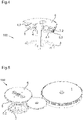
figure 1 est une vue éclatée du mécanisme de déclenchement d'une animation selon l'invention. - La
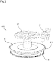
figure 2 est une vue en perspective du mécanisme de déclenchement d'une animation selon l'invention. - La
figure 3 illustre le mécanisme de déclenchement d'une animation selon l'invention vu face au mobile de commande du mécanisme. - La
figure 4 est une vue en coupe du mécanisme de déclenchement d'une animation selon l'invention. - La
figure 5 est une vue en perspective d'une partie du mécanisme de déclenchement d'une animation selon l'invention avec son barillet. - La
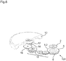
figure 6 est une vue en perspective d'une autre partie du mécanisme de déclenchement d'une animation selon l'invention avec la masse oscillante balourdée. - Les
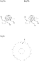
figures 7a et 7b illustrent le mobile d'embrayage et le mobile de transmission liés à la masse oscillante balourdée dans deux positions distinctes. - La
figure 8 illustre une variante du mobile de commande du mécanisme de déclenchement d'une animation illustré aux figures précédentes. - Le mécanisme de déclenchement d'une animation selon l'invention est destiné à mettre en mouvement un objet à animer tel qu'un personnage, un animal, une fleur ou tout autre élément décoratif afin d'obtenir un effet divertissant. L'invention ne portant pas directement sur l'objet à animer, sa forme et ses mouvements, ceux-ci ne sont pas illustrés et ne seront pas décrits plus en détail ci-après.
- Le mécanisme de déclenchement d'une animation selon l'invention est destiné à déclencher les mouvements de l'objet à animer à des moments quasi aléatoires qui dépendent notamment de la vitesse et des déplacements d'une masse oscillante balourdée montée libre en rotation par rapport au mécanisme de déclenchement d'une animation. De préférence, cette masse oscillante est également agencée pour remonter un organe moteur fournissant l'énergie nécessaire au mécanisme de déclenchement d'une animation.
- Le mécanisme de déclenchement d'une animation selon l'invention est notamment destiné à équiper une pièce d'horlogerie. En variante, le mécanisme de déclenchement d'une animation selon l'invention pourrait également équiper un bijou ou tout autre objet approprié.
- Dans la forme d'exécution illustrée aux figures, le mécanisme de déclenchement d'une animation 100 selon l'invention équipe une pièce d'horlogerie munie d'un mouvement à remontage automatique comprenant une masse oscillante de remontage.
- Le mécanisme de déclenchement d'une animation 100 comprend un organe moteur qui est dans la forme d'exécution illustrée, un barillet d'animation 1. De préférence, le barillet d'animation 1 est distinct du barillet principal du mouvement de la pièce d'horlogerie et est destiné exclusivement au mécanisme de déclenchement d'une animation 100. En variante, l'organe moteur pourrait être le barillet du mouvement de la pièce d'horlogerie ou tout autre organe moteur approprié qu'il soit dédié exclusivement ou non au mécanisme de déclenchement d'une animation 100.
- Dans la forme d'exécution illustrée, le barillet d'animation 1 est remonté par une masse oscillante balourdée 10 et un mécanisme de remontage approprié.
- Le mécanisme de déclenchement d'une animation 100 comprend un mobile de commande destiné à commander le déclenchement des mouvements de l'objet à animer. Le mobile de commande est pivoté en rotation selon un axe de rotation dont la position est indépendante de la position de l'axe de rotation de la masse oscillante balourdée 10. Dans la forme d'exécution illustrée, le mobile de commande est une came de commande 2 ayant la forme d'une étoile dont les dents sont réparties de manière irrégulière sur sa circonférence. La came de commande 2 est destinée à coopérer avec une bascule de déclenchement 3 pour le déclenchement de l'animation.
- Le barillet d'animation 1 est relié cinématiquement à la came de commande 2 pour fournir l'énergie nécessaire au déclenchement de l'animation. L'énergie du barillet d'animation 1 et la chaîne cinématique le reliant à la came de commande 2 détermine donc une vitesse de base pour la came de commande 2 qui impose un rythme pour le déclenchement de l'animation en l'absence de mouvements de la masse oscillante 10. Par exemple, cette vitesse de base de la came de commande 2 peut être telle que le déclenchement de l'animation via la came de commande 2, dont la denture est irrégulière, et la bascule de déclenchement 3 a lieu toutes les 3 +/- 1 minutes soit environ vingt fois par heure. En variante, le déclenchement de l'animation peut également être entraîné par le mouvement de la pièce d'horlogerie et avoir lieu à des moments prédéterminés, par exemple à chaque heure.
- Selon l'invention, la came de commande 2 est liée cinématiquement avec un mobile de transmission 16 auquel sont transmis les mouvements de la masse oscillante 10. Ce mobile de transmission 16 peut être commandé par les mouvements de la masse oscillante 10 quel que soit son sens de rotation, et il peut soit tourner dans les deux sens soit en un seul sens comme un mobile d'inversion dans un mécanisme de remontage automatique. Alternativement, le mobile de transmission 16 peut être commandé par les mouvements de la masse oscillante 10 dans un seul sens de rotation.
- Selon la forme d'exécution illustrée de l'invention, le mécanisme de déclenchement d'une animation 100 comprend un système d'engrenage planétaire dont la sortie détermine la vitesse de rotation de la came de commande 2. De préférence, le système d'engrenage planétaire présente deux entrées indépendantes : une première entrée est reliée à l'organe moteur du mécanisme de déclenchement d'une animation 100 (voir la
figure 5 ) tandis que la seconde entrée est reliée à la masse oscillante (voir lafigure 6 ). Dans la forme d'exécution illustrée, la première entrée du système planétaire est reliée au tambour du barillet d'animation 1 tandis que la seconde entrée est reliée à la masse oscillante 10. - Dans la forme d'exécution illustrée, le système d'engrenage planétaire du mécanisme de déclenchement d'une animation 100 comprend un premier mobile planétaire 6 qui constitue la première entrée du système et qui est relié par une chaîne cinématique au tambour du barillet d'animation 1 comme illustré à la
figure 5 . Ce premier mobile planétaire 6 est agencé pour servir de porte-satellite à un premier satellite 7.1 et à un second satellite 7.2 pivotés sur des rayons diamétralement opposés du premier mobile planétaire 6. Les premier et second satellites 7.1, 7.2 engrènent avec un pignon solaire 4, qui est solidaire de la came de commande 2, en des points diamétralement opposés. Ce pignon solaire 4 constitue donc la sortie du système d'engrenage planétaire. Les satellites 7.1 et 7.2 sont en prise avec la denture intérieure 5.1 d'un second mobile planétaire ayant ici la forme d'une couronne 5. La denture extérieure 5.2 de la couronne 5 constitue la seconde entrée du système planétaire et est reliée cinématiquement via une chaîne cinématique avec la masse oscillante 10. Ainsi, les mouvements de la couronne 5 dépendent des déplacements et de la vitesse de la masse oscillante 10. - Dans la présente forme d'exécution, la masse oscillante 10 et le mécanisme de remontage sont agencés pour remonter le barillet d'animation 1 seulement dans un sens de rotation de la masse oscillante 10. Comme illustré en particulier à
figure 6 , la masse oscillante 10 est reliée au mobile de transmission 16 par un mécanisme d'embrayage comprenant une bascule d'embrayage 12 portant un pignon d'embrayage 14. Selon le sens de rotation de la masse oscillante 10, la bascule d'embrayage 12 se déplace et le pignon d'embrayage 14 est soit dans une position embrayée dans laquelle il coopère avec le mobile de transmission 16 (figure 7a ) soit dans une position débrayée dans laquelle il n'est pas en prise avec le mobile de transmission 16 (figure 7b ). Ainsi, le mobile de transmission 16 tourne donc en fonction des déplacements de la masse oscillante 10 dans son sens de remontage. Le mobile de transmission 16 est lié à la denture extérieure 5.2 de la couronne 5 par un rouage 18 qui lui aussi peut comprendre un autre engrenage planétaire, comme illustré sur lafigure 6 . - Ainsi, lorsque la masse oscillante 10 tourne et alimente le barillet d'animation 1, la couronne 5 est entraînée via le mobile de transmission 16 et le rouage 18 en prise avec sa denture extérieure 5.2, avec pour conséquence de varier la vitesse de base de la came de commande 2 (déterminée par le barillet d'animation 1) en sortie du système d'engrenage planétaire. Les moments de déclenchement de l'animation deviennent alors aléatoires quand la pièce d'horlogerie est portée au poignet d'un utilisateur.
- La vitesse de la came de commande 2 est donc déterminée par la force motrice du barillet d'animation 1 transmise au pignon solaire 4 et à la came de commande 2 par le premier mobile planétaire 6 et les premier et second satellites 7.1, 7.2 et par les mouvements de la masse oscillante 10 transmis par le mobile de transmission 16 et le rouage 18 à la couronne 5. Le déclenchement de l'animation dépend donc de la vitesse et des mouvements de la masse oscillante 10 (dans un sens du moins dans la forme d'exécution illustrée) et ce déclenchement devient alors essentiellement aléatoire dans le cas d'une montre-bracelet.
- La
figure 8 illustre une variante de la came de commande qui est dans ce cas une étoile 2' dont les dents sont réparties irrégulièrement à sa circonférence et ont des hauteurs irrégulières. Une telle came de commande 2' permet de déclencher l'animation pendant des durées proportionnelles à la hauteur de ses dents ce qui permet de renforcer encore le caractère aléatoire du mécanisme. - Dans la forme d'exécution illustrée, le mobile de commande est taillé de manière irrégulière pour accentuer le caractère aléatoire de l'animation. En variante, le mobile de commande pourrait être taillé de manière régulière, le système d'engrenage planétaire et les mouvements aléatoires ou quasi-aléatoires de la masse oscillante garantissant le caractère aléatoire de l'animation.
- Le mécanisme de déclenchement d'une animation selon l'invention peut être utilisé pour animer toute sorte d'objet dans des domaines variés comme la joaillerie ou l'horlogerie. Le caractère aléatoire de l'animation est obtenu par un mécanisme simple mais efficace et qui s'adapte à un grand nombre de situations. Par exemple, dans la forme d'exécution avec une bascule 3 venant palper une came de commande 2, le déclenchement de l'animation peut être instantané, tout en laissant la possibilité d'un déclenchement du mécanisme de déclenchement d'une animation à la demande via un mécanisme approprié.
Claims (14)
- Mécanisme de déclenchement d'une animation (100) permettant de mettre en mouvement un objet à animer afin d'obtenir un effet divertissant, l'objet à animer étant un élément décoratif , par exemple un personnage, une figurine, un animal ou une fleur, le mécanisme comprenant un mobile de commande (2) et une bascule de déclenchement (3), le mobile de commande (2) étant destiné à coopérer avec la bascule de déclenchement (3) pour le déclenchement de l'animation de l'objet à des moments quasi-aléatoires, un organe moteur (1) relié cinématiquement au mobile de commande (2) et une masse oscillante balourdée (10) montée libre en rotation par rapport au mécanisme de déclenchement de ladite animation, dans lequel le mobile de commande (2) est relié cinématiquement à l'organe moteur (1) afin de lui imposer une vitesse de rotation de base, le mobile de commande (2) étant également relié cinématiquement à un mobile de transmission (16) auquel sont transmis des mouvements de la masse oscillante balourdée (10) pour que la vitesse du mobile de commande (2) et ainsi les moments de déclenchement de l'animation de l'objet varient en fonction des mouvements de la masse oscillante balourdée (10).
- Mécanisme de déclenchement d'une animation (100) selon la revendication 1, caractérisé par le fait que la position de l'axe de rotation du mobile de commande (2) est indépendante de la position de l'axe de rotation de la masse oscillante balourdée (10).
- Mécanisme de déclenchement d'une animation (100) selon la revendication 1 ou 2, caractérisé par le fait que la masse oscillante balourdée (10) est une masse de remontage reliée cinématiquement à l'organe moteur (1) pour remonter ce dernier automatiquement.
- Mécanisme de déclenchement d'une animation (100) selon l'une des revendications précédentes, caractérisé par le fait qu'il comprend un système d'engrenage planétaire ayant une première entrée (6) reliée cinématiquement à l'organe moteur (1), une deuxième entrée (5) reliée cinématiquement à la masse oscillante balourdée (10) et une sortie (4) reliée cinématiquement au mobile de commande (2).
- Mécanisme de déclenchement d'une animation (100) selon la revendication 4, caractérisé par le fait que l'organe moteur est un barillet (1) dont le tambour est relié cinématiquement au système d'engrenage planétaire.
- Mécanisme de déclenchement d'une animation (100) selon l'une des revendications précédentes, caractérisé par le fait que le mobile de commande (2) est taillé aléatoirement.
- Mécanisme selon l'une de revendications précédentes, caractérisé par le fait que le mobile de commande est une came de commande (2).
- Mécanisme selon la revendication précédente 7, caractérisé par le fait que la came de commande (2) est une étoile dont les dents sont réparties de manière irrégulière sur sa circonférence.
- Mécanisme selon la revendication précédente 8, caractérisé par le fait que la hauteur des dents de l'étoile (2') est également irrégulière.
- Mécanisme selon l'une des revendications 4 à 9 quand les revendications 6 et 7 dépendent de la revendication 4, caractérisé par le fait que le
système d'engrenage planétaire comprend un pignon solaire (4) solidaire du mobile de commande (2), un premier mobile planétaire (6) relié cinématiquement à l'organe moteur (1) et un deuxième mobile planétaire (5) dont la denture extérieure (5.2) est reliée cinématiquement à la masse oscillante balourdée (10) et dont la denture intérieure (5.1) est en prise avec des premier et second satellites (7.1, 7.2) pivotés sur ledit premier mobile planétaire (6), lesdits premier et second satellites (7.1, 7.2) engrenant également avec le pignon solaire (4). - Mécanisme selon l'une des revendications précédentes, caractérisé par le fait que le mécanisme est en outre agencé pour que seuls les mouvements de la masse oscillante balourdée (10) dans un sens de rotation déterminé soient transmis au mobile de transmission (16) et donc au mobile de commande (2) pour faire varier la vitesse de ce dernier et les moments de déclenchement de l'animation de l'objet.
- Mécanisme selon l'une des revendications 1 à 10, caractérisé par le fait que le mécanisme est en outre agencé pour que tous les mouvements de la masse oscillante balourdée (10), quel que soit son sens de rotation, soient transmis au mobile de transmission (16) et donc au mobile de commande (2) pour faire varier la vitesse de ce dernier et les moments de déclenchement de l'animation de l'objet.
- Mécanisme selon l'une des revendications précédentes, caractérisé par le fait que l'élément décoratif est un personnage, une figurine, un animal ou une fleur.
- Pièce d'horlogerie comprenant un mécanisme de déclenchement d'une animation (100) selon l'une des revendications précédentes, la pièce d'horlogerie étant une montre-bracelet.
Applications Claiming Priority (1)
| Application Number | Priority Date | Filing Date | Title |
|---|---|---|---|
| CH000598/2016A CH712439B1 (fr) | 2016-05-06 | 2016-05-06 | Mécanisme d'animation et pièce d'horlogerie comprenant un tel mécanisme. |
Publications (2)
| Publication Number | Publication Date |
|---|---|
| EP3242166A1 EP3242166A1 (fr) | 2017-11-08 |
| EP3242166B1 true EP3242166B1 (fr) | 2022-06-15 |
Family
ID=55963105
Family Applications (1)
| Application Number | Title | Priority Date | Filing Date |
|---|---|---|---|
| EP17169441.7A Active EP3242166B1 (fr) | 2016-05-06 | 2017-05-04 | Mécanisme de déclenchement d'une animation |
Country Status (2)
| Country | Link |
|---|---|
| EP (1) | EP3242166B1 (fr) |
| CH (1) | CH712439B1 (fr) |
Families Citing this family (2)
| Publication number | Priority date | Publication date | Assignee | Title |
|---|---|---|---|---|
| CH717249A1 (fr) * | 2020-03-20 | 2021-09-30 | Cartier Int Ag | Système de démarrage et d'arrêt d'une fonction et montre comportant un tel système. |
| CH717672B1 (fr) * | 2020-07-21 | 2023-08-31 | Richemont Int Sa | Mécanisme de déclenchement d'une animation pour pièce d'horlogerie ou de bijouterie. |
Family Cites Families (8)
| Publication number | Priority date | Publication date | Assignee | Title |
|---|---|---|---|---|
| CH403368A (fr) | 1962-09-05 | 1965-11-30 | Kaufman Samuel Jack | Dispositif pour entraîner un mobile en rotation |
| EP1672441A1 (fr) * | 2004-12-14 | 2006-06-21 | Giuseppe Chines | Cadran de montre avec masses oscillantes |
| ATE421718T1 (de) * | 2006-02-22 | 2009-02-15 | Blancpain Sa | Selbstaufzuguhr mit einem gangreserveanzeiger |
| FR2921164B1 (fr) * | 2007-09-19 | 2009-12-04 | Grisogono Sa De | Module d'affichage sequentiel,notamment pour le masquage ou la visualisation sequentielle d'une complication d'horlogerie |
| CH699455B1 (fr) * | 2008-09-05 | 2013-03-28 | Montres Paul Picot S A Soc D | Mécanisme d'affichage d'une information périodique. |
| CH702592A1 (fr) * | 2010-01-27 | 2011-07-29 | Frederic Jouvenot | Mécanisme d'affichage de la réserve de marche. |
| EP2360535B1 (fr) * | 2010-02-24 | 2012-12-05 | Blancpain S.A. | Masse oscillante pour montre à remontage automatique, comportant un dispositif indicateur de la réserve de marche intégré dans ladite masse oscillante |
| CH704622B1 (fr) | 2011-03-14 | 2016-03-15 | Christophe Claret S A | Pièce d'horlogerie. |
-
2016
- 2016-05-06 CH CH000598/2016A patent/CH712439B1/fr unknown
-
2017
- 2017-05-04 EP EP17169441.7A patent/EP3242166B1/fr active Active
Also Published As
| Publication number | Publication date |
|---|---|
| EP3242166A1 (fr) | 2017-11-08 |
| CH712439B1 (fr) | 2023-10-31 |
| CH712439A1 (fr) | 2017-11-15 |
Similar Documents
| Publication | Publication Date | Title |
|---|---|---|
| EP2214065B1 (fr) | Mouvement d'horlogerie muni d'une alarme vibrante | |
| EP0973076B1 (fr) | Montre à tourbillon | |
| EP0756217B1 (fr) | Mécanisme de quantième annuel pour pièce d'horlogerie | |
| EP3612897B1 (fr) | Dispositif de blocage pour l'horlogerie | |
| EP2527930B1 (fr) | Montre comprenant un mécanisme d'affichage d'une animation | |
| EP3874331B1 (fr) | Masse oscillante à géométrie variable pour mécanisme horloger | |
| EP1607807B1 (fr) | Pièce d'horlogerie à effets esthétiques spéciaux | |
| EP3242166A1 (fr) | Mécanisme de déclenchement d'une animation | |
| CH707181B1 (fr) | Dispositif horloger comprenant un organe de commande lié cinématiquement à une roue de seconde sautante. | |
| WO2021023710A1 (fr) | Piece de joaillerie ou bijouterie comprenant un mecanisme d'animation d'un objet | |
| EP3475764B1 (fr) | Mouvement d'horlogerie | |
| EP1784691A1 (fr) | Mecanisme d'affichage de chiffres, figures ou signes animes sur un cadran de piece d'horlogerie | |
| EP3772674B1 (fr) | Pièce de joaillerie ou de bijouterie comportant un mécanisme d`animation d'un objet | |
| CH700035B1 (fr) | Mouvement d'horlogerie muni d'un mécanisme d'embrayage inertiel. | |
| CH707182A2 (fr) | Dispositif horloger. | |
| EP2177959B1 (fr) | Mécanisme d'entraînement d'aiguilles | |
| EP2990880B1 (fr) | Mouvement d'horlogerie | |
| CH707183A2 (fr) | Dispositif horloger. | |
| CH716486A2 (fr) | Mécanisme d'animation d'un objet pour pièce de joaillerie ou de bijouterie. | |
| CH699143B1 (fr) | Mécanisme d'affichage. | |
| FR2921164A1 (fr) | Module d'affichage sequentiel,notamment pour le masquage ou la visualisation sequentielle d'une complication d'horlogerie | |
| EP2990881B1 (fr) | Mouvement d'horlogerie | |
| EP2990879B1 (fr) | Mouvement d'horlogerie | |
| EP3783444A1 (fr) | Mecanisme horloger comprenant un dispositif de blocage | |
| CH93849A (fr) | Indicateur de temps. |
Legal Events
| Date | Code | Title | Description |
|---|---|---|---|
| PUAI | Public reference made under article 153(3) epc to a published international application that has entered the european phase |
Free format text: ORIGINAL CODE: 0009012 |
|
| STAA | Information on the status of an ep patent application or granted ep patent |
Free format text: STATUS: THE APPLICATION HAS BEEN PUBLISHED |
|
| AK | Designated contracting states |
Kind code of ref document: A1 Designated state(s): AL AT BE BG CH CY CZ DE DK EE ES FI FR GB GR HR HU IE IS IT LI LT LU LV MC MK MT NL NO PL PT RO RS SE SI SK SM TR |
|
| AX | Request for extension of the european patent |
Extension state: BA ME |
|
| STAA | Information on the status of an ep patent application or granted ep patent |
Free format text: STATUS: REQUEST FOR EXAMINATION WAS MADE |
|
| 17P | Request for examination filed |
Effective date: 20180426 |
|
| RBV | Designated contracting states (corrected) |
Designated state(s): AL AT BE BG CH CY CZ DE DK EE ES FI FR GB GR HR HU IE IS IT LI LT LU LV MC MK MT NL NO PL PT RO RS SE SI SK SM TR |
|
| STAA | Information on the status of an ep patent application or granted ep patent |
Free format text: STATUS: EXAMINATION IS IN PROGRESS |
|
| 17Q | First examination report despatched |
Effective date: 20200309 |
|
| RIN1 | Information on inventor provided before grant (corrected) |
Inventor name: STRAUMANN, KURT Inventor name: MAGNIN-FEYSOT, ERIC Inventor name: MEIER, WILLY Inventor name: BERNARD, RAINER Inventor name: STALDER, NICOLAS |
|
| GRAP | Despatch of communication of intention to grant a patent |
Free format text: ORIGINAL CODE: EPIDOSNIGR1 |
|
| STAA | Information on the status of an ep patent application or granted ep patent |
Free format text: STATUS: GRANT OF PATENT IS INTENDED |
|
| INTG | Intention to grant announced |
Effective date: 20220408 |
|
| GRAS | Grant fee paid |
Free format text: ORIGINAL CODE: EPIDOSNIGR3 |
|
| GRAA | (expected) grant |
Free format text: ORIGINAL CODE: 0009210 |
|
| STAA | Information on the status of an ep patent application or granted ep patent |
Free format text: STATUS: THE PATENT HAS BEEN GRANTED |
|
| AK | Designated contracting states |
Kind code of ref document: B1 Designated state(s): AL AT BE BG CH CY CZ DE DK EE ES FI FR GB GR HR HU IE IS IT LI LT LU LV MC MK MT NL NO PL PT RO RS SE SI SK SM TR |
|
| REG | Reference to a national code |
Ref country code: CH Ref legal event code: EP Ref country code: GB Ref legal event code: FG4D Free format text: NOT ENGLISH |
|
| REG | Reference to a national code |
Ref country code: IE Ref legal event code: FG4D Free format text: LANGUAGE OF EP DOCUMENT: FRENCH |
|
| REG | Reference to a national code |
Ref country code: DE Ref legal event code: R096 Ref document number: 602017058459 Country of ref document: DE |
|
| REG | Reference to a national code |
Ref country code: AT Ref legal event code: REF Ref document number: 1498736 Country of ref document: AT Kind code of ref document: T Effective date: 20220715 |
|
| REG | Reference to a national code |
Ref country code: LT Ref legal event code: MG9D |
|
| REG | Reference to a national code |
Ref country code: NL Ref legal event code: MP Effective date: 20220615 |
|
| PG25 | Lapsed in a contracting state [announced via postgrant information from national office to epo] |
Ref country code: SE Free format text: LAPSE BECAUSE OF FAILURE TO SUBMIT A TRANSLATION OF THE DESCRIPTION OR TO PAY THE FEE WITHIN THE PRESCRIBED TIME-LIMIT Effective date: 20220615 Ref country code: NO Free format text: LAPSE BECAUSE OF FAILURE TO SUBMIT A TRANSLATION OF THE DESCRIPTION OR TO PAY THE FEE WITHIN THE PRESCRIBED TIME-LIMIT Effective date: 20220915 Ref country code: LT Free format text: LAPSE BECAUSE OF FAILURE TO SUBMIT A TRANSLATION OF THE DESCRIPTION OR TO PAY THE FEE WITHIN THE PRESCRIBED TIME-LIMIT Effective date: 20220615 Ref country code: HR Free format text: LAPSE BECAUSE OF FAILURE TO SUBMIT A TRANSLATION OF THE DESCRIPTION OR TO PAY THE FEE WITHIN THE PRESCRIBED TIME-LIMIT Effective date: 20220615 Ref country code: GR Free format text: LAPSE BECAUSE OF FAILURE TO SUBMIT A TRANSLATION OF THE DESCRIPTION OR TO PAY THE FEE WITHIN THE PRESCRIBED TIME-LIMIT Effective date: 20220916 Ref country code: FI Free format text: LAPSE BECAUSE OF FAILURE TO SUBMIT A TRANSLATION OF THE DESCRIPTION OR TO PAY THE FEE WITHIN THE PRESCRIBED TIME-LIMIT Effective date: 20220615 Ref country code: BG Free format text: LAPSE BECAUSE OF FAILURE TO SUBMIT A TRANSLATION OF THE DESCRIPTION OR TO PAY THE FEE WITHIN THE PRESCRIBED TIME-LIMIT Effective date: 20220915 |
|
| REG | Reference to a national code |
Ref country code: AT Ref legal event code: MK05 Ref document number: 1498736 Country of ref document: AT Kind code of ref document: T Effective date: 20220615 |
|
| PG25 | Lapsed in a contracting state [announced via postgrant information from national office to epo] |
Ref country code: RS Free format text: LAPSE BECAUSE OF FAILURE TO SUBMIT A TRANSLATION OF THE DESCRIPTION OR TO PAY THE FEE WITHIN THE PRESCRIBED TIME-LIMIT Effective date: 20220615 Ref country code: LV Free format text: LAPSE BECAUSE OF FAILURE TO SUBMIT A TRANSLATION OF THE DESCRIPTION OR TO PAY THE FEE WITHIN THE PRESCRIBED TIME-LIMIT Effective date: 20220615 |
|
| PG25 | Lapsed in a contracting state [announced via postgrant information from national office to epo] |
Ref country code: NL Free format text: LAPSE BECAUSE OF FAILURE TO SUBMIT A TRANSLATION OF THE DESCRIPTION OR TO PAY THE FEE WITHIN THE PRESCRIBED TIME-LIMIT Effective date: 20220615 |
|
| PG25 | Lapsed in a contracting state [announced via postgrant information from national office to epo] |
Ref country code: SM Free format text: LAPSE BECAUSE OF FAILURE TO SUBMIT A TRANSLATION OF THE DESCRIPTION OR TO PAY THE FEE WITHIN THE PRESCRIBED TIME-LIMIT Effective date: 20220615 Ref country code: SK Free format text: LAPSE BECAUSE OF FAILURE TO SUBMIT A TRANSLATION OF THE DESCRIPTION OR TO PAY THE FEE WITHIN THE PRESCRIBED TIME-LIMIT Effective date: 20220615 Ref country code: RO Free format text: LAPSE BECAUSE OF FAILURE TO SUBMIT A TRANSLATION OF THE DESCRIPTION OR TO PAY THE FEE WITHIN THE PRESCRIBED TIME-LIMIT Effective date: 20220615 Ref country code: PT Free format text: LAPSE BECAUSE OF FAILURE TO SUBMIT A TRANSLATION OF THE DESCRIPTION OR TO PAY THE FEE WITHIN THE PRESCRIBED TIME-LIMIT Effective date: 20221017 Ref country code: ES Free format text: LAPSE BECAUSE OF FAILURE TO SUBMIT A TRANSLATION OF THE DESCRIPTION OR TO PAY THE FEE WITHIN THE PRESCRIBED TIME-LIMIT Effective date: 20220615 Ref country code: EE Free format text: LAPSE BECAUSE OF FAILURE TO SUBMIT A TRANSLATION OF THE DESCRIPTION OR TO PAY THE FEE WITHIN THE PRESCRIBED TIME-LIMIT Effective date: 20220615 Ref country code: CZ Free format text: LAPSE BECAUSE OF FAILURE TO SUBMIT A TRANSLATION OF THE DESCRIPTION OR TO PAY THE FEE WITHIN THE PRESCRIBED TIME-LIMIT Effective date: 20220615 Ref country code: AT Free format text: LAPSE BECAUSE OF FAILURE TO SUBMIT A TRANSLATION OF THE DESCRIPTION OR TO PAY THE FEE WITHIN THE PRESCRIBED TIME-LIMIT Effective date: 20220615 |
|
| PG25 | Lapsed in a contracting state [announced via postgrant information from national office to epo] |
Ref country code: PL Free format text: LAPSE BECAUSE OF FAILURE TO SUBMIT A TRANSLATION OF THE DESCRIPTION OR TO PAY THE FEE WITHIN THE PRESCRIBED TIME-LIMIT Effective date: 20220615 Ref country code: IS Free format text: LAPSE BECAUSE OF FAILURE TO SUBMIT A TRANSLATION OF THE DESCRIPTION OR TO PAY THE FEE WITHIN THE PRESCRIBED TIME-LIMIT Effective date: 20221015 |
|
| REG | Reference to a national code |
Ref country code: DE Ref legal event code: R097 Ref document number: 602017058459 Country of ref document: DE |
|
| PG25 | Lapsed in a contracting state [announced via postgrant information from national office to epo] |
Ref country code: AL Free format text: LAPSE BECAUSE OF FAILURE TO SUBMIT A TRANSLATION OF THE DESCRIPTION OR TO PAY THE FEE WITHIN THE PRESCRIBED TIME-LIMIT Effective date: 20220615 |
|
| PLBE | No opposition filed within time limit |
Free format text: ORIGINAL CODE: 0009261 |
|
| STAA | Information on the status of an ep patent application or granted ep patent |
Free format text: STATUS: NO OPPOSITION FILED WITHIN TIME LIMIT |
|
| PG25 | Lapsed in a contracting state [announced via postgrant information from national office to epo] |
Ref country code: DK Free format text: LAPSE BECAUSE OF FAILURE TO SUBMIT A TRANSLATION OF THE DESCRIPTION OR TO PAY THE FEE WITHIN THE PRESCRIBED TIME-LIMIT Effective date: 20220615 |
|
| 26N | No opposition filed |
Effective date: 20230316 |
|
| PG25 | Lapsed in a contracting state [announced via postgrant information from national office to epo] |
Ref country code: SI Free format text: LAPSE BECAUSE OF FAILURE TO SUBMIT A TRANSLATION OF THE DESCRIPTION OR TO PAY THE FEE WITHIN THE PRESCRIBED TIME-LIMIT Effective date: 20220615 |
|
| PG25 | Lapsed in a contracting state [announced via postgrant information from national office to epo] |
Ref country code: MC Free format text: LAPSE BECAUSE OF FAILURE TO SUBMIT A TRANSLATION OF THE DESCRIPTION OR TO PAY THE FEE WITHIN THE PRESCRIBED TIME-LIMIT Effective date: 20220615 |
|
| REG | Reference to a national code |
Ref country code: BE Ref legal event code: MM Effective date: 20230531 |
|
| PG25 | Lapsed in a contracting state [announced via postgrant information from national office to epo] |
Ref country code: MC Free format text: LAPSE BECAUSE OF FAILURE TO SUBMIT A TRANSLATION OF THE DESCRIPTION OR TO PAY THE FEE WITHIN THE PRESCRIBED TIME-LIMIT Effective date: 20220615 Ref country code: LU Free format text: LAPSE BECAUSE OF NON-PAYMENT OF DUE FEES Effective date: 20230504 Ref country code: IT Free format text: LAPSE BECAUSE OF FAILURE TO SUBMIT A TRANSLATION OF THE DESCRIPTION OR TO PAY THE FEE WITHIN THE PRESCRIBED TIME-LIMIT Effective date: 20220615 |
|
| REG | Reference to a national code |
Ref country code: IE Ref legal event code: MM4A |
|
| PG25 | Lapsed in a contracting state [announced via postgrant information from national office to epo] |
Ref country code: IE Free format text: LAPSE BECAUSE OF NON-PAYMENT OF DUE FEES Effective date: 20230504 |
|
| PG25 | Lapsed in a contracting state [announced via postgrant information from national office to epo] |
Ref country code: IE Free format text: LAPSE BECAUSE OF NON-PAYMENT OF DUE FEES Effective date: 20230504 |
|
| PG25 | Lapsed in a contracting state [announced via postgrant information from national office to epo] |
Ref country code: BE Free format text: LAPSE BECAUSE OF NON-PAYMENT OF DUE FEES Effective date: 20230531 |
|
| REG | Reference to a national code |
Ref country code: DE Ref legal event code: R081 Ref document number: 602017058459 Country of ref document: DE Owner name: RICHEMONT INTERNATIONAL SA, CH Free format text: FORMER OWNER: VAN CLEEF&ARPELS SA, VILLARS-SUR-GLANE, CH |
|
| PG25 | Lapsed in a contracting state [announced via postgrant information from national office to epo] |
Ref country code: BG Free format text: LAPSE BECAUSE OF FAILURE TO SUBMIT A TRANSLATION OF THE DESCRIPTION OR TO PAY THE FEE WITHIN THE PRESCRIBED TIME-LIMIT Effective date: 20220615 |
|
| REG | Reference to a national code |
Ref country code: GB Ref legal event code: 732E Free format text: REGISTERED BETWEEN 20241024 AND 20241030 |
|
| PG25 | Lapsed in a contracting state [announced via postgrant information from national office to epo] |
Ref country code: BG Free format text: LAPSE BECAUSE OF FAILURE TO SUBMIT A TRANSLATION OF THE DESCRIPTION OR TO PAY THE FEE WITHIN THE PRESCRIBED TIME-LIMIT Effective date: 20220615 |
|
| PGFP | Annual fee paid to national office [announced via postgrant information from national office to epo] |
Ref country code: DE Payment date: 20250521 Year of fee payment: 9 |
|
| PGFP | Annual fee paid to national office [announced via postgrant information from national office to epo] |
Ref country code: GB Payment date: 20250521 Year of fee payment: 9 |
|
| PGFP | Annual fee paid to national office [announced via postgrant information from national office to epo] |
Ref country code: FR Payment date: 20250528 Year of fee payment: 9 |
|
| PGFP | Annual fee paid to national office [announced via postgrant information from national office to epo] |
Ref country code: CH Payment date: 20250601 Year of fee payment: 9 |
|
| PG25 | Lapsed in a contracting state [announced via postgrant information from national office to epo] |
Ref country code: CY Free format text: LAPSE BECAUSE OF FAILURE TO SUBMIT A TRANSLATION OF THE DESCRIPTION OR TO PAY THE FEE WITHIN THE PRESCRIBED TIME-LIMIT; INVALID AB INITIO Effective date: 20170504 |
|
| PG25 | Lapsed in a contracting state [announced via postgrant information from national office to epo] |
Ref country code: HU Free format text: LAPSE BECAUSE OF FAILURE TO SUBMIT A TRANSLATION OF THE DESCRIPTION OR TO PAY THE FEE WITHIN THE PRESCRIBED TIME-LIMIT; INVALID AB INITIO Effective date: 20170504 |
|
| PG25 | Lapsed in a contracting state [announced via postgrant information from national office to epo] |
Ref country code: TR Free format text: LAPSE BECAUSE OF FAILURE TO SUBMIT A TRANSLATION OF THE DESCRIPTION OR TO PAY THE FEE WITHIN THE PRESCRIBED TIME-LIMIT Effective date: 20220615 |