EP3242130A1 - Sample collection, thermal analysis, and sample injection apparatus and method, and trace detection device - Google Patents
Sample collection, thermal analysis, and sample injection apparatus and method, and trace detection device Download PDFInfo
- Publication number
- EP3242130A1 EP3242130A1 EP15860000.7A EP15860000A EP3242130A1 EP 3242130 A1 EP3242130 A1 EP 3242130A1 EP 15860000 A EP15860000 A EP 15860000A EP 3242130 A1 EP3242130 A1 EP 3242130A1
- Authority
- EP
- European Patent Office
- Prior art keywords
- sample
- thermal desorption
- piston
- chamber
- adsorption cavity
- Prior art date
- Legal status (The legal status is an assumption and is not a legal conclusion. Google has not performed a legal analysis and makes no representation as to the accuracy of the status listed.)
- Granted
Links
- 238000002347 injection Methods 0.000 title claims abstract description 55
- 239000007924 injection Substances 0.000 title claims abstract description 55
- 238000001514 detection method Methods 0.000 title claims abstract description 28
- 238000000034 method Methods 0.000 title claims abstract description 12
- 238000002076 thermal analysis method Methods 0.000 title 1
- 238000003795 desorption Methods 0.000 claims abstract description 116
- 238000001179 sorption measurement Methods 0.000 claims abstract description 89
- 238000004891 communication Methods 0.000 claims abstract description 46
- 239000007789 gas Substances 0.000 claims description 40
- 238000005070 sampling Methods 0.000 claims description 29
- 238000001816 cooling Methods 0.000 claims description 21
- 239000003463 adsorbent Substances 0.000 claims description 14
- 210000002445 nipple Anatomy 0.000 claims description 14
- 238000009413 insulation Methods 0.000 claims description 13
- 239000012159 carrier gas Substances 0.000 claims description 11
- 239000002274 desiccant Substances 0.000 claims description 10
- 238000010438 heat treatment Methods 0.000 claims description 9
- 238000007789 sealing Methods 0.000 claims description 8
- 238000005086 pumping Methods 0.000 claims description 6
- 239000012141 concentrate Substances 0.000 claims description 2
- 238000001871 ion mobility spectroscopy Methods 0.000 description 21
- 239000000126 substance Substances 0.000 description 13
- 238000004094 preconcentration Methods 0.000 description 8
- 238000004458 analytical method Methods 0.000 description 7
- 238000005516 engineering process Methods 0.000 description 7
- 239000000356 contaminant Substances 0.000 description 6
- 150000001875 compounds Chemical class 0.000 description 5
- 239000000203 mixture Substances 0.000 description 5
- 238000000926 separation method Methods 0.000 description 4
- 239000000463 material Substances 0.000 description 3
- 239000004810 polytetrafluoroethylene Substances 0.000 description 3
- 229920001343 polytetrafluoroethylene Polymers 0.000 description 3
- 239000000243 solution Substances 0.000 description 3
- 229920000742 Cotton Polymers 0.000 description 2
- 230000009471 action Effects 0.000 description 2
- 238000011161 development Methods 0.000 description 2
- 238000010586 diagram Methods 0.000 description 2
- 239000003814 drug Substances 0.000 description 2
- 229940079593 drug Drugs 0.000 description 2
- 150000002500 ions Chemical class 0.000 description 2
- 230000005012 migration Effects 0.000 description 2
- 238000013508 migration Methods 0.000 description 2
- 238000012544 monitoring process Methods 0.000 description 2
- 238000002203 pretreatment Methods 0.000 description 2
- 230000035945 sensitivity Effects 0.000 description 2
- 230000002411 adverse Effects 0.000 description 1
- 230000005540 biological transmission Effects 0.000 description 1
- 239000000919 ceramic Substances 0.000 description 1
- 238000006243 chemical reaction Methods 0.000 description 1
- 231100000481 chemical toxicant Toxicity 0.000 description 1
- 239000000112 cooling gas Substances 0.000 description 1
- 230000007547 defect Effects 0.000 description 1
- 230000007613 environmental effect Effects 0.000 description 1
- 239000002360 explosive Substances 0.000 description 1
- 238000004817 gas chromatography Methods 0.000 description 1
- 238000002290 gas chromatography-mass spectrometry Methods 0.000 description 1
- 238000002309 gasification Methods 0.000 description 1
- 239000003779 heat-resistant material Substances 0.000 description 1
- 238000007689 inspection Methods 0.000 description 1
- 238000004519 manufacturing process Methods 0.000 description 1
- 239000011159 matrix material Substances 0.000 description 1
- 238000012986 modification Methods 0.000 description 1
- 230000004048 modification Effects 0.000 description 1
- 230000003533 narcotic effect Effects 0.000 description 1
- 239000013618 particulate matter Substances 0.000 description 1
- 238000002360 preparation method Methods 0.000 description 1
- 230000004044 response Effects 0.000 description 1
- 239000002904 solvent Substances 0.000 description 1
- 238000010408 sweeping Methods 0.000 description 1
- 239000003440 toxic substance Substances 0.000 description 1
- XLYOFNOQVPJJNP-UHFFFAOYSA-N water Substances O XLYOFNOQVPJJNP-UHFFFAOYSA-N 0.000 description 1
Images


Classifications
-
- G—PHYSICS
- G01—MEASURING; TESTING
- G01N—INVESTIGATING OR ANALYSING MATERIALS BY DETERMINING THEIR CHEMICAL OR PHYSICAL PROPERTIES
- G01N1/00—Sampling; Preparing specimens for investigation
- G01N1/02—Devices for withdrawing samples
-
- G—PHYSICS
- G01—MEASURING; TESTING
- G01N—INVESTIGATING OR ANALYSING MATERIALS BY DETERMINING THEIR CHEMICAL OR PHYSICAL PROPERTIES
- G01N1/00—Sampling; Preparing specimens for investigation
- G01N1/02—Devices for withdrawing samples
- G01N1/22—Devices for withdrawing samples in the gaseous state
- G01N1/2202—Devices for withdrawing samples in the gaseous state involving separation of sample components during sampling
- G01N1/2214—Devices for withdrawing samples in the gaseous state involving separation of sample components during sampling by sorption
-
- G—PHYSICS
- G01—MEASURING; TESTING
- G01N—INVESTIGATING OR ANALYSING MATERIALS BY DETERMINING THEIR CHEMICAL OR PHYSICAL PROPERTIES
- G01N1/00—Sampling; Preparing specimens for investigation
- G01N1/02—Devices for withdrawing samples
- G01N1/22—Devices for withdrawing samples in the gaseous state
- G01N1/2202—Devices for withdrawing samples in the gaseous state involving separation of sample components during sampling
- G01N1/2211—Devices for withdrawing samples in the gaseous state involving separation of sample components during sampling with cyclones
-
- G—PHYSICS
- G01—MEASURING; TESTING
- G01N—INVESTIGATING OR ANALYSING MATERIALS BY DETERMINING THEIR CHEMICAL OR PHYSICAL PROPERTIES
- G01N1/00—Sampling; Preparing specimens for investigation
- G01N1/02—Devices for withdrawing samples
- G01N1/22—Devices for withdrawing samples in the gaseous state
- G01N1/2273—Atmospheric sampling
-
- G—PHYSICS
- G01—MEASURING; TESTING
- G01N—INVESTIGATING OR ANALYSING MATERIALS BY DETERMINING THEIR CHEMICAL OR PHYSICAL PROPERTIES
- G01N1/00—Sampling; Preparing specimens for investigation
- G01N1/28—Preparing specimens for investigation including physical details of (bio-)chemical methods covered elsewhere, e.g. G01N33/50, C12Q
- G01N1/40—Concentrating samples
- G01N1/405—Concentrating samples by adsorption or absorption
-
- G—PHYSICS
- G01—MEASURING; TESTING
- G01N—INVESTIGATING OR ANALYSING MATERIALS BY DETERMINING THEIR CHEMICAL OR PHYSICAL PROPERTIES
- G01N30/00—Investigating or analysing materials by separation into components using adsorption, absorption or similar phenomena or using ion-exchange, e.g. chromatography or field flow fractionation
- G01N30/02—Column chromatography
- G01N30/04—Preparation or injection of sample to be analysed
- G01N30/06—Preparation
- G01N30/08—Preparation using an enricher
-
- H—ELECTRICITY
- H01—ELECTRIC ELEMENTS
- H01J—ELECTRIC DISCHARGE TUBES OR DISCHARGE LAMPS
- H01J49/00—Particle spectrometers or separator tubes
- H01J49/02—Details
- H01J49/04—Arrangements for introducing or extracting samples to be analysed, e.g. vacuum locks; Arrangements for external adjustment of electron- or ion-optical components
- H01J49/0422—Arrangements for introducing or extracting samples to be analysed, e.g. vacuum locks; Arrangements for external adjustment of electron- or ion-optical components for gaseous samples
-
- H—ELECTRICITY
- H01—ELECTRIC ELEMENTS
- H01J—ELECTRIC DISCHARGE TUBES OR DISCHARGE LAMPS
- H01J49/00—Particle spectrometers or separator tubes
- H01J49/02—Details
- H01J49/04—Arrangements for introducing or extracting samples to be analysed, e.g. vacuum locks; Arrangements for external adjustment of electron- or ion-optical components
- H01J49/0459—Arrangements for introducing or extracting samples to be analysed, e.g. vacuum locks; Arrangements for external adjustment of electron- or ion-optical components for solid samples
-
- H—ELECTRICITY
- H01—ELECTRIC ELEMENTS
- H01J—ELECTRIC DISCHARGE TUBES OR DISCHARGE LAMPS
- H01J49/00—Particle spectrometers or separator tubes
- H01J49/02—Details
- H01J49/04—Arrangements for introducing or extracting samples to be analysed, e.g. vacuum locks; Arrangements for external adjustment of electron- or ion-optical components
- H01J49/0468—Arrangements for introducing or extracting samples to be analysed, e.g. vacuum locks; Arrangements for external adjustment of electron- or ion-optical components with means for heating or cooling the sample
-
- G—PHYSICS
- G01—MEASURING; TESTING
- G01N—INVESTIGATING OR ANALYSING MATERIALS BY DETERMINING THEIR CHEMICAL OR PHYSICAL PROPERTIES
- G01N1/00—Sampling; Preparing specimens for investigation
- G01N1/28—Preparing specimens for investigation including physical details of (bio-)chemical methods covered elsewhere, e.g. G01N33/50, C12Q
- G01N1/38—Diluting, dispersing or mixing samples
-
- G—PHYSICS
- G01—MEASURING; TESTING
- G01N—INVESTIGATING OR ANALYSING MATERIALS BY DETERMINING THEIR CHEMICAL OR PHYSICAL PROPERTIES
- G01N1/00—Sampling; Preparing specimens for investigation
- G01N1/28—Preparing specimens for investigation including physical details of (bio-)chemical methods covered elsewhere, e.g. G01N33/50, C12Q
- G01N1/42—Low-temperature sample treatment, e.g. cryofixation
-
- G—PHYSICS
- G01—MEASURING; TESTING
- G01N—INVESTIGATING OR ANALYSING MATERIALS BY DETERMINING THEIR CHEMICAL OR PHYSICAL PROPERTIES
- G01N30/00—Investigating or analysing materials by separation into components using adsorption, absorption or similar phenomena or using ion-exchange, e.g. chromatography or field flow fractionation
- G01N30/02—Column chromatography
- G01N30/04—Preparation or injection of sample to be analysed
- G01N30/06—Preparation
- G01N30/12—Preparation by evaporation
- G01N2030/126—Preparation by evaporation evaporating sample
- G01N2030/128—Thermal desorption analysis
Definitions
- Embodiments of the present invention generally relate to the field of safety detection technology, and in particular, to sample injection device and method for sample collection and sample thermal desorption, and a trace detection apparatus, which are capable of performing real-time collection and pre-concentration of volatile substance, semi-volatile substance, surface contaminant or the like, and which are suitable for fast sample collection and injection for Gas Chromatograph (GC), Ion Mobility Spectrometry (IMS), Gas Chromatography-Ion Mobility Spectrometry (GC-IMS) combination spectrometer or the like.
- GC Gas Chromatograph
- IMS Ion Mobility Spectrometry
- GC-IMS Gas Chromatography-Ion Mobility Spectrometry
- IMS Ion Mobility Spectrometry
- the IMS as a detection instrument alone, encounters the following problems: (1) due to problems on the manufacturing process, currently commercial IMS only has a resolution ratio of about 30, which is difficult in differentiating chemical compounds having similar migration rates from one another; (2) ions from some chemical compounds undergo complicate reaction and annihilate each other in the ionization zone; (3) the IMS has a relatively lower dynamic range, so that, when there is/are one or several type(s) of chemical compounds with greatly large concentration(s), generations of ions of other types of chemical compounds will be adversely affected, which results in missed detection. Based on the above reasons, it is prone to trigger of false alarm or failing of alarm when a complex mixture having many types of chemical compounds is detected by the IMS.
- Gas chromatography - ion mobility spectrometry (GC-IMS) combination technology has an excellently separation ability on complicated sample, and is capable of performing a pre-separation on the mixture, to separate the mixture into single components to be detected by the IMS. This combination technology will greatly enhance accuracy of the detection on the mixture.
- Conventional GC's analysis time is in order of magnitude of ten minutes or more, so it is difficult to meet demands on on-site fast detection.
- fast GC technology has been developed rapidly, and its separation time (of tens of seconds - minutes) is greatly shortened compared to conventional GC.
- Fast GC-IMS inherits the separation ability of the GC, and on the other hand, succeeds to high sensitivity, fast response speed characteristics of the IMS, accordingly, it is capable of detecting complex components of the sample with a detection limit that is superior to the ppb order of magnitude and a detection time from a few minutes to tens of minutes.
- the fast GC-IMS reflects full advantages in the aspects of miniaturization and portable, is very suitable for on-site fast detection of a sample including complex components. This technology will play a powerful role in fields including anti-terrorism and riot control, drug smudging, environmental monitoring, food safety, and so on.
- Sample injector is an integral part of a trace analytical instrument.
- Main sampling modes for a separate IMS comprise a wipe sampling thermal desorption mode and a direct sampling thermal desorption mode.
- the wipe sampling mode generally includes: wiping a substance to be detected by using a high temperature resistant wiping paper with a certain flexibility, and then, the sampling paper is put into a slot of the thermal desorption sample injector so that the substance adhered to the sampling paper is thermally desorbed by heating.
- This mode is only suitable for the sampling on surface contaminants, but is not suitable for the direct sampling on volatile or semi-volatile substances.
- the GC has sample injection requirements, which are different from those of the IMS, including rapid gasification of the sample's components, and rapid, accurate and quantitative application on the GC's column head after being mixed with the carrier gas. Accordingly, the existing IMS sample injection methods are not suitable for the GC-IMS in principle or in the sampling efficiency.
- split/ splitless sampling modes are used generally for solution samples; in these modes, however, not only interference of sample matrix on analysis needs to be considered, but also interference of sample solvents on analysis needs to be considered. Meanwhile, the sample further needs to be subject to a complicated pre-treatment, which is not suitable for on-site fast detection. Although a currently widely used head space sample injection does not require a complicated pre-treatment, it still “destructively" obtains a certain amount of sample, so it is not suitable for fast on-site detection for the trace gas without unpacking.
- the present invention is provided.
- a sample injection device for sample collection and sample thermal desorption, comprising: a sample collection structure; a piston type adsorber having an adsorption cavity that is capable of being arranged to be in communication with the sample collection structure and configured to adsorb a sample collected by the sample collection structure; a piston cylinder defining a piston chamber that is configured for accommodating the piston type adsorber and configured to be in communication with the adsorption cavity; a thermal desorption chamber that is configured to be in communication with the adsorption cavity and the piston chamber and is configured to thermally desorb the sample adsorbed in the adsorption cavity; and a pump that is configured to be in communication with the piston chamber via a conduit and is configured to pump a sample diffused in an ambient gas into the adsorption cavity through the sample collection structure; wherein the piston type adsorber is configured to be movable between a sample collecting position where the adsorption cavity is located outside the thermal desorption chamber and in communication with the sample collection structure so as
- the sample collection structure may comprise a sample collection opening, a filter structure mounted onto or over the sample collection opening and a connection tube connecting the sample collection opening to the piston cylinder; and the piston cylinder may comprise a cylinder body that is mounted to the thermal desorption chamber and is provided with a sampling connection gas nipple being in communication with the piston chamber, and one end of the connection tube is configured to be mounted hermetically and detachably to the sampling connection gas nipple.
- a desiccant for adsorption of moisture in the sample may be placed within the connection tube.
- connection tube comprises a retractable hose.
- the piston type adsorber may comprise a piston rod body and the adsorption cavity connected to a distal end of the piston rod body, and the adsorption cavity comprises a net-like structure filled with adsorbents therein.
- the adsorption cavity may comprise an adsorption passage configured to be in communication with the sample collection structure to receive the collected sample when the piston type adsorber is located at the sample collecting position.
- the piston type adsorber may further comprise a thermal insulation pad detachably connected to one end of the adsorption cavity away from the piston rod body.
- the piston rod body may comprise a cooling passage and a plurality of through holes formed in a lower part of the piston rod body;
- the cooling passage may be configured to be in direct communication with the ambient gas when the piston type adsorber is located at the sample collecting position, and in communication with the ambient gas via a cooling through hole formed in the piston cylinder when the piston type adsorber is located at the sample desorbing position, and the plurality of through holes are configured to be in communication with the cooling passage and the piston chamber.
- the above sample injection device may further comprise a plurality of sealing rings provided around the piston type adsorber such that the piston type adsorber is hermetically accommodated within the piston cylinder.
- the piston cylinder may comprise a guide rail provided within the thermal desorption chamber to guide a movement of the piston type adsorber within the thermal desorption chamber.
- the thermal desorption chamber may comprise a chamber body and a liner provided on an inner wall of the chamber body, and an outer wall of the chamber body may be covered with a heating structure.
- the thermal desorption chamber may be further provided with a carrier gas inlet, a gas outlet and an analyzer interface.
- the above sample injection device may further comprise a thermal insulation structure provided between the piston cylinder and the thermal desorption chamber. O-rings may be provided among the three components, to form a hermetical desorption chamber.
- a trace detection apparatus comprising: the abovementioned sample injection device for sample collection and sample thermal desorption; and a sample analyzer connected to the sample injection device.
- a method of collecting and desorbing a sample by using the abovementioned sample injection device comprising steps of: positioning the piston type adsorber into the sample collecting position so that the adsorption cavity is in communication with the sample collection structure; pumping a sample diffused in the ambient gas into the adsorption cavity through the sample collection structure by starting up the pump; maintaining a temperature inside thermal desorption chamber at a constant high temperature by using a thermal desorption temperature-controlling system; and moving and positioning the piston type adsorber into the sample desorbing position so that the adsorption cavity is located within the thermal desorption chamber and the sample adsorbed within the adsorption cavity is thermally desorbed within the thermal desorption chamber at the high temperature.
- the pump may be kept working to continuously pump the sample and to pre-concentrate the sample within the adsorption cavity.
- the pump may be started up to pump gas so that a portion of the piston type adsorber outside the thermal desorption chamber is kept at a room temperature.
- a sample injection device for sample collection and sample thermal desorption comprising: a sample collection structure; a piston type adsorber having an adsorption cavity that is capable of being arranged to be in communication with the sample collection structure and configured to adsorb the sample collected by a sample collection structure; a piston cylinder defining a piston chamber that is configured for accommodating the piston type adsorber and configured to be in communication with the adsorption cavity; a thermal desorption chamber that is configured to be in communication with the adsorption cavity and the piston chamber and is configured to thermally desorb the sample adsorbed in the adsorption cavity; and a pump that is configured to be in communication with the piston chamber via a conduit and is configured to pump a sample diffused in an ambient gas into the adsorption cavity through the sample collection structure; wherein the piston type adsorber is configured to be movable between a sample collecting position where the adsorption cavity is located outside the thermal desorption chamber and in communication with the sample collection structure so
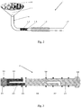
- Fig. 1 schematically shows a configuration of a sample injection device for sample collection and sample thermal desorption according to an exemplary embodiment of the present invention.
- the sample injection device for sample collection and sample thermal desorption mainly comprises a sample collection structure 1, a piston type adsorber 2, a piston cylinder 3, a thermal desorption chamber 4 and a pump 5. Structures and operations of these components will be described in detail hereafter.
- Fig. 2 shows schematically an example of a sample collection structure according to the present invention.
- the sample collection structure 1 mainly comprises a sample collection opening 1-1, a filter structure 1-2 mounted to the sample collection opening 1-1, and a connection tube 1-3 connecting the sample collection opening 1-1 with the piston cylinder 3.
- the sample collection opening 1-1 may have a trumpet shape, and will be placed in an ambient gas where a sample to be collected is leaked or where a sample having surface contaminants is present during sampling, thereby effectively enlarging a sample collecting area and facilitating fast collection of the sample.
- the filter structure 1-2 such as a filter screen, mounted to a front end of the sample collection opening 1-1, may prevent the tube from being blocked due to entrance of large particulate matter(s).
- the sample collection opening 1-1 is connected to and in communication with the piston cylinder 3 through the connection tube 1-2.
- Desiccant 1-4 which is able to adsorb water and moisture contained in the collected sample during the sample collection, may be placed within the connection tube 1-2, in order to protect the chromatographic column and the migration tube of the analytic instrument.
- the desiccant may be contained in a desiccant bag.
- Structure 1-5 for fixation of the desiccant or the desiccant bag, such as a protrusion, may be provided in the connection tube, preventing movement of the desiccant or the desiccant bag under the pumping action of the pump.
- connection tube 1-2 comprises a retractable hose or bellows 1-6.
- This retractable hose or bellows 1-6 may be stretched and/or rotated during sampling, to adjust an orientation of the sample collection opening 1-1, thereby greatly facilitating the sample collection implemented by a user.
- a distal end 1-7 of the connection tube 1-2 is configured for being connected hermetically and detachably to the piston cylinder 3.
- Fig. 3 shows schematically an example of a piston type adsorber according to the present invention.
- the piston type adsorber 2 is in a form of wholly cylindrical piston that may be reciprocated within the piston cylinder 3, and mainly comprises a piston rod body 2-1 and an adsorption cavity 2-2 connected to a distal end of the piston rod body 2-1.
- the piston rod body 2-1 may be made of a chemically stable heat resistant material, such as PTFE.
- the adsorption cavity 2-2 may comprise a net-like structure filled with adsorbents 2-3 therein, that is, mesh holes are formed in walls of the cavity and the adsorbents 2-3 are filled within the cavity.
- Adsorbent materials having different adsorption characteristics may be added selectively in accordance with different detection demands. Such on-demand selection enhances selective adsorption on the sample to be detected, to a certain extent. It will be understood that, a diameter of the adsorbent filled should be greater than a size or diameter of the mesh hole.
- the adsorption cavity 2-2 may be in a partially hollow form, that is, it may comprise an adsorption passage 2-6, which is L-shaped or walking stick-shaped and has an opening in the wall of the cavity.
- the adsorption passage is configured to be in communication with the sample collection structure during sampling, so as to receive the sample adsorbed via the connection tube 1-3.
- the piston rod body 2-1 may comprise a cooling passage 2-7 and a plurality of through holes 2-8 formed in a lower part of the piston rod body.
- the cooling passage 2-7 is configured to be in direct communication with the ambient gas when the piston type adsorber is located at the sample collecting position, and to be in communication with the ambient gas through a cooling through hole formed in the piston cylinder when the piston type adsorber is located at the sample desorbing position.
- the cooling passage 2-7 may also be L-shaped or walking stick-shaped and have an opening to the ambient gas.
- the through holes 2-8 are configured to communicate with the cooling passage 2-7 and interior of the piston chamber 3.
- This hollow piston rod body will reduce mass of the piston type adsorber and facilitate rapid heating and cooling of the adsorber, and on the other hand, may communicate the pump 5 with a cooling gas inlet 3-5 at an upper part of the piston cylinder 3 (see Figs. 1 and 4 ) during smaple injection, such that he upper part of the adsorber may be air-cooled by pumping of the pump, which speeds up a cooling rate at the upper part of the piston type adsorber and helps to rapidly cool down the adsorption cavity at the lower part of the piston type adsorber together with the adsorbents therein, facilitating adsorption of the sample.
- the piston type adsorber 2 may further comprise a thermal insulation pad 2-4 detachably connected to one end of the adsorption cavity 2-2 away from the piston rod body 2-1. That is, the adsorption cavity 2-2 is disposed between the piston rod body 2-1 and the thermal insulation pad 2-4.
- the piston type adsorber may be pulled out or the piston cylinder may be unscrewed, and then the thermal insulation pad located at bottom of the adsorber is unscrewed and removed, so that the adsorbents within the adsorption cavity may be replaced.
- the thermal insulation pad may be made of a PTFE material.
- Provision of the thermal insulation pad will reduce thermal transmission from the thermal desorption chamber to the adsorption cavity, effectively ensuring that the adsorption cavity as well as the adsorbents is kept cool, e.g., at near room temperature, during sampling/collection at the piston type adsorber, facilitating adsorption and collection of the sample.
- a plurality of sealing rings 2-5 is fitted over the piston type adsorber 2, such as over an outer surface of the piston type adsorber 2, such that the piston type adsorber 2 is hermetically received in the piston cylinder 3.
- the sealing rings 2-5 are arranged such that when the piston type adsorber 2 reciprocates between a highest position (for example, a sample collecting position) and a lowest position (for example, a sample desorbing position) within the piston cylinder 3, the piston type adsorber 2 is kept in a seal contact with an inner wall of the piston cylinder 3 via the sealing rings 2-5, as shown in Figs. 1 and 4 .
- some of the sealing rings 2-5 are disposed at positions near the opening of the adsorption passage 2-6 and at positions near the opening of the cooling passage 2-7, as shown in Fig. 3 .
- a push-and-pull handle 2-9 may be disposed at a distal end of the piston rod body 2-1 of the piston type adsorber 2, and is configured for moving the piston type adsorber 2 reciprocally within the piston cylinder 3 by means of push and pull actions implemented by the user.
- the piston cylinder 3 mainly comprises a cylinder body 3-1, and a piston chamber 3-2 for receiving the piston type adsorber 2 and being in communication with the adsorption cavity 2-2.
- the cylinder body 3-1 may be made of PTFE material having high strength, good heat resistance and stable chemical properties, and defines at least a portion of the piston chamber 3-2.
- the cylinder body 3-1 is mounted on the thermal desorption chamber 4 and is provided with a sampling connection gas nipple 3-3 in communication with the piston chamber 3-2.
- connection tube 1-3 of the sample collection structure 1 may be mounted or inserted hermetically and detachably to the sampling connection gas nipple 3-3, so that a communication between an inner sample passage of the sample collection structure 1 and the piston chamber 3-2 is achieved.
- a valve for controlling on/off of this communication may be provided in the sampling connection gas nipple 3-3.
- the cylinder body 3-1 is further provided with a pump connection gas nipple 3-4, and the pump 5 is connected to the gas nipple 3-4 through a conduct 5-1 so as to be in communication with the piston chamber 3-2.
- the pump 5, the conduit 5-1, the pump connection gas nipple 3-4, the piston chamber 3-2, the sampling connection gas nipple 3-3, the connection tube 1-3, and the sample collection opening 1-1 constitute a communication path.
- a sample to be sampled e.g., volatile or semi-volatile substance, or surface contaminants
- the pump 5 works continuously so that the sample is adsorbed/pre-concentrated in the adsorption cavity.
- the whole piston type adsorber is kept at room temperature.
- the piston cylinder 3 may further comprise a guide rail 3-6 provided within the thermal desorption chamber 4 to guide a movement of the piston type adsorber 2 within the thermal desorption chamber 2, thereby effectively preventing the piston type adsorber 2 from shaking, and improving degree of the firmness.
- the guide rail 3-6 is connected to the cylinder body 3-1 and defines a portion of the piston chamber 3-2.
- Form of the guide rail 3-6 is not limited. In an example, there may be two parallel rod-like rails, or the guide rail may be in a cylindrical form.
- the thermal desorption chamber 4 mainly comprises a chamber body 4-1, and an internal space defined by the chamber body 4-1 and adapted for thermal desorption of the sample.
- the chamber body 4-1 is formed with a carrier gas inlet 4-2, a shunting and/or sweeping gas outlet 4-3, and an interface 4-4 for connection to an analytical instrument such as chromatographic column, IMS or the like.
- a liner 4-5 having stable chemical performance may be embedded hermetically in the chamber body of the thermal desorption chamber 4 and will effectively prevent a direct contact between the sample and a metallic wall of the thermal desorption chamber.
- the liner 4-5 may be replaced regularly, which can avoid a direct pollution of the thermal desorption chamber by the sample, reduce a sample distortion rate, and enhance accuracy and reliability of the sample detection.
- An outer wall of the chamber body of the thermal desorption chamber 204 may be provided with a heating structure or a heating film, for heating the thermal desorption chamber 4.
- the thermal desorption chamber 3-10 may be provided with a temperature sensor, for example on the outer surface of the chamber body, for real time detecting and monitoring the temperature within the thermal desorption chamber.
- the outer wall of the chamber body of the thermal desorption chamber 204 may be covered with a thermal insulation cotton for thermally insulating the thermal desorption chamber, so as to reduce the power consumption.
- the heating structure, the temperature sensor and/or the thermal insulation cotton are components of a thermal desorption temperature controlling system, which keep the temperature of the thermal desorption chamber at a constant temperature, e.g., 80°C ⁇ 300°C, under the control of a controller.
- the thermal desorption chamber may adopt a programmed heating mode, which reduces the power consumption.
- Thermal insulation structure 4-6 for example, porous ceramic thermal insulation disc, may be provided or inserted between the thermal desorption chamber 204 and the piston cylinder 203, and can effectively insulate a heat exchange between the thermal desorption chamber and the upper part of the piston type adsorber (e.g., the piston rod body) during desorption of the sample, and can also effectively insulate a heat exchange between the thermal desorption chamber and the piston type adsorber and a heat exchange between the thermal desorption chamber and the upper part of the piston cylinder during collection of the sample. This ensures the whole piston type adsorber is kept at the room temperature during collection of the sample, facilitating collection of the sample.
- the piston type adsorber e.g., the piston rod body
- the thermal desorption temperature controlling system is operated firstly to maintain the temperature in the thermal desorption chamber at a suitably constant high temperature (80°C ⁇ 300°C).
- the piston type adsorber adsorbed with the sample is pushed quickly into the thermal desorption chamber at the high temperature.
- the adsorbents pushed into the thermal desorption chamber are heated rapidly so that the sample adsorbed in the adsorption cavity will be thermal desorbed instantly at the high temperature.
- the desorbed sample will be mixed with preheated carrier gas introduced the carrier gas inlet of the thermal desorption chamber through, and finally is taken by the carrier gas into the detection device or the analytical instrument for detection or analysis.
- the pump 5, the piston chamber 3-2, the plurality of through holes 2-8 formed in the piston rod body, the cooling passage 2-7, and the cooling air inlet 3-5 formed in the piston cylinder 3 constitute a communication path while the adsorption cavity is pushed into the thermal desorption chamber. Accordingly, the upper part (including the piston rod body) of the piston type adsorber outside the thermal desorption chamber will be air cooled by the air exhaust operation of the pump 5, which facilitates a next sample adsorption and enrichment or pre-concentration.
- This sample injection device for sample collection and sample thermal desorption has the sample enrichment or pre-concentration function and thus may be used directly as an IMS instrument or GC, or be served as a sample injector for chemical substance trace analytical instruments including IMS-GC, GC-MS, etc., and it needs not to give unnecessary details herein.
- the piston type adsorber 2 is pulled to be positioned at the sample collecting position as shown in Fig. 1 , such that the adsorption cavity 2-2 is in communication with the sample collection structure 1.
- the pump 5, the conduit 5-1, the pump connection gas nipple 3-4, a portion of the piston chamber 3-2 (including the portion surrounding the adsorption cavity), the sampling connection gas nipple 3-3, the connection tube 1-3 and the sample collection opening 1-1 constitute a communication path by means of the sealing rings 2-5.
- the pump 5 is started up, so that a sample to be sampled (for example, volatile substances, semi-volatile substances or surface contaminants) in the ambient gas is suctioned into the adsorption cavity 2-2, and is adsorbed/pre-concentrated in the adsorption cavity 2-2.
- a sample to be sampled for example, volatile substances, semi-volatile substances or surface contaminants
- the pump 5 may operate continuously so that the sample is enriched or pre-concentrated within the adsorption cavity.
- the whole piston type adsorber may be kept at a room temperature.
- the thermal desorption temperature controlling system is started up, so that the temperature of the thermal desorption chamber 4 is kept at a constant high temperature.
- the piston type adsorber 2 is moved rapidly to be positioned at the sample desorbing position as shown in Fig. 4 , so that the adsorption cavity 2-2 is positioned within the thermal desorption chamber 4.
- the adsorption cavity 2-2 may be sealed by the sealing rings 2-5 within the lower part of the piston chamber 3-2, so that it is sealed within the thermal desorption chamber 4.
- the adsorbents that are pushed into the thermal desorption chamber 4 are heated up rapidly so that the sample adsorbed in the adsorption cavity 2-2 is desorbed instantly at high temperature.
- the desorbed sample is mixed with a pre-heated carrier gas 4-2 imported from the carrier gas inlet 4-2 of the thermal desorption chamber 4, and finally, is brought by the carrier gas into a detection device or analytical instrument (not shown), for detection or analysis.
- the pump 5, the conduit 5-1, the pump connection gas nipple 3-4, a portion of the piston chamber 3-2 (namely the portion outside the thermal desorption chamber 4), the plurality of through holes 2-8 formed in the piston rod body 2-1, the cooling passage 2-7, and the cooling air inlet 3-5 in the piston cylinder 3 constitute a path or space that is in communication with the ambient gas. Accordingly, the upper half part of the piston type adsorber 2 outside the thermal desorption chamber 4 is air-cooled by the suction function of the pump 5, so that temperature of the part of the piston type adsorber positioned outside the thermal desorption chamber is maintained at a room temperature, facilitating a next sample adsorption and enrichment or pre-concentration.
- samples of volatile or semi-volatile substances or surface contaminants may be obtained by performing direct sample adsorption and collection on a surface to be detected or in the ambient gas atmosphere.
- the obtained sample may be thermally desorbed within the thermal desorption chamber, and then is brought by the carrier gas into a chromatograph or IMS spectrometer for detection or analysis.
- the sample injection device for sample collection and sample thermal desorption the sample will be pre-concentrated or enriched in the adsorption cavity or onto the adsorbents therein by a continuous pumping operation of a suction pump.
- Pre-concentration of the sample may lower the requirements on a lower detection limit of the detector such as IMS and the like, and reduce difficulty and cost of instrument development.
- sample injection device for sample collection and sample thermal desorption self air suction and cooling will be achieved, which facilitates a next sample adsorption and collection or pre-concentration.
- the sample injection device of the present invention integrates sample collection, pre-concentration and thermal desorption functions, needs no external head space equipment, requires no preparation of solution and no unpacking for sampling, saves space and time, facilitates miniaturization and portable development of the instrument, increases the throughout of the instrument, and, is very advantageous to on-site rapid detections at airport, customs and so on.
Landscapes
- Life Sciences & Earth Sciences (AREA)
- Health & Medical Sciences (AREA)
- Chemical & Material Sciences (AREA)
- Analytical Chemistry (AREA)
- Physics & Mathematics (AREA)
- Pathology (AREA)
- Biochemistry (AREA)
- General Health & Medical Sciences (AREA)
- General Physics & Mathematics (AREA)
- Immunology (AREA)
- Molecular Biology (AREA)
- Biomedical Technology (AREA)
- Engineering & Computer Science (AREA)
- Sampling And Sample Adjustment (AREA)
- Other Investigation Or Analysis Of Materials By Electrical Means (AREA)
- Spectroscopy & Molecular Physics (AREA)
- Chemical Kinetics & Catalysis (AREA)
- Electrochemistry (AREA)
Abstract
Description
- Embodiments of the present invention generally relate to the field of safety detection technology, and in particular, to sample injection device and method for sample collection and sample thermal desorption, and a trace detection apparatus, which are capable of performing real-time collection and pre-concentration of volatile substance, semi-volatile substance, surface contaminant or the like, and which are suitable for fast sample collection and injection for Gas Chromatograph (GC), Ion Mobility Spectrometry (IMS), Gas Chromatography-Ion Mobility Spectrometry (GC-IMS) combination spectrometer or the like.
- Ion Mobility Spectrometry (IMS) technology has advantages of simple structure, high sensitivity, and fast analysis speed. It is able to achieve a fast trace (in ppb order of magnitude) detection on a substance under atmospheric pressure or near atmospheric pressure, and is very suitable for in-field use. Accordingly, IMS is widely applied for detection or inspection in various aspects including toxic chemical, narcotic drugs, explosives, environments, etc.. However, during detection of mixtures, the IMS, as a detection instrument alone, encounters the following problems: (1) due to problems on the manufacturing process, currently commercial IMS only has a resolution ratio of about 30, which is difficult in differentiating chemical compounds having similar migration rates from one another; (2) ions from some chemical compounds undergo complicate reaction and annihilate each other in the ionization zone; (3) the IMS has a relatively lower dynamic range, so that, when there is/are one or several type(s) of chemical compounds with greatly large concentration(s), generations of ions of other types of chemical compounds will be adversely affected, which results in missed detection. Based on the above reasons, it is prone to trigger of false alarm or failing of alarm when a complex mixture having many types of chemical compounds is detected by the IMS.
- Gas chromatography - ion mobility spectrometry (GC-IMS) combination technology has an excellently separation ability on complicated sample, and is capable of performing a pre-separation on the mixture, to separate the mixture into single components to be detected by the IMS. This combination technology will greatly enhance accuracy of the detection on the mixture. Conventional GC's analysis time is in order of magnitude of ten minutes or more, so it is difficult to meet demands on on-site fast detection. In recent years, fast GC technology has been developed rapidly, and its separation time (of tens of seconds - minutes) is greatly shortened compared to conventional GC. Fast GC-IMS, on one hand, inherits the separation ability of the GC, and on the other hand, succeeds to high sensitivity, fast response speed characteristics of the IMS, accordingly, it is capable of detecting complex components of the sample with a detection limit that is superior to the ppb order of magnitude and a detection time from a few minutes to tens of minutes. In addition, the fast GC-IMS reflects full advantages in the aspects of miniaturization and portable, is very suitable for on-site fast detection of a sample including complex components. This technology will play a powerful role in fields including anti-terrorism and riot control, drug smudging, environmental monitoring, food safety, and so on.
- Sample injector is an integral part of a trace analytical instrument. Main sampling modes for a separate IMS comprise a wipe sampling thermal desorption mode and a direct sampling thermal desorption mode. The wipe sampling mode generally includes: wiping a substance to be detected by using a high temperature resistant wiping paper with a certain flexibility, and then, the sampling paper is put into a slot of the thermal desorption sample injector so that the substance adhered to the sampling paper is thermally desorbed by heating. This mode is only suitable for the sampling on surface contaminants, but is not suitable for the direct sampling on volatile or semi-volatile substances. In addition, the GC has sample injection requirements, which are different from those of the IMS, including rapid gasification of the sample's components, and rapid, accurate and quantitative application on the GC's column head after being mixed with the carrier gas. Accordingly, the existing IMS sample injection methods are not suitable for the GC-IMS in principle or in the sampling efficiency.
- For a conventional GC sample injector, split/ splitless sampling modes are used generally for solution samples; in these modes, however, not only interference of sample matrix on analysis needs to be considered, but also interference of sample solvents on analysis needs to be considered. Meanwhile, the sample further needs to be subject to a complicated pre-treatment, which is not suitable for on-site fast detection. Although a currently widely used head space sample injection does not require a complicated pre-treatment, it still "destructively" obtains a certain amount of sample, so it is not suitable for fast on-site detection for the trace gas without unpacking.
- In a word, conventional IMS and GC technologies have low efficiency in sample collection and sample injection, low collection speed, and requires unpacking, which is not suitable for fast GC-IMS on-site detection.
- In order to overcome at least one of the abovementioned problems and defects existing in the prior art, the present invention is provided.
- According to an aspect of the present invention, there is provided a sample injection device for sample collection and sample thermal desorption, comprising: a sample collection structure; a piston type adsorber having an adsorption cavity that is capable of being arranged to be in communication with the sample collection structure and configured to adsorb a sample collected by the sample collection structure; a piston cylinder defining a piston chamber that is configured for accommodating the piston type adsorber and configured to be in communication with the adsorption cavity; a thermal desorption chamber that is configured to be in communication with the adsorption cavity and the piston chamber and is configured to thermally desorb the sample adsorbed in the adsorption cavity; and a pump that is configured to be in communication with the piston chamber via a conduit and is configured to pump a sample diffused in an ambient gas into the adsorption cavity through the sample collection structure; wherein the piston type adsorber is configured to be movable between a sample collecting position where the adsorption cavity is located outside the thermal desorption chamber and in communication with the sample collection structure so as to adsorb the sample collected by the sample collection structure and a sample desorbing position where the adsorption cavity is located inside the thermal desorption chamber so that the adsorbed sample is thermally desorbed in the thermal desorption chamber.
- In the above sample injection device for sample collection and sample thermal desorption, the sample collection structure may comprise a sample collection opening, a filter structure mounted onto or over the sample collection opening and a connection tube connecting the sample collection opening to the piston cylinder; and the piston cylinder may comprise a cylinder body that is mounted to the thermal desorption chamber and is provided with a sampling connection gas nipple being in communication with the piston chamber, and one end of the connection tube is configured to be mounted hermetically and detachably to the sampling connection gas nipple.
- In the above sample injection device for sample collection and sample thermal desorption, a desiccant for adsorption of moisture in the sample may be placed within the connection tube.
- In the above sample injection device for sample collection and sample thermal desorption, at least a portion of the connection tube comprises a retractable hose.
- In the above sample injection device for sample collection and sample thermal desorption, the piston type adsorber may comprise a piston rod body and the adsorption cavity connected to a distal end of the piston rod body, and the adsorption cavity comprises a net-like structure filled with adsorbents therein.
- In the above sample injection device for sample collection and sample thermal desorption, the adsorption cavity may comprise an adsorption passage configured to be in communication with the sample collection structure to receive the collected sample when the piston type adsorber is located at the sample collecting position.
- In the above sample injection device for sample collection and sample thermal desorption, the piston type adsorber may further comprise a thermal insulation pad detachably connected to one end of the adsorption cavity away from the piston rod body.
- In the above sample injection device for sample collection and sample thermal desorption, the piston rod body may comprise a cooling passage and a plurality of through holes formed in a lower part of the piston rod body; the cooling passage may be configured to be in direct communication with the ambient gas when the piston type adsorber is located at the sample collecting position, and in communication with the ambient gas via a cooling through hole formed in the piston cylinder when the piston type adsorber is located at the sample desorbing position, and the plurality of through holes are configured to be in communication with the cooling passage and the piston chamber.
- The above sample injection device may further comprise a plurality of sealing rings provided around the piston type adsorber such that the piston type adsorber is hermetically accommodated within the piston cylinder.
- In the above sample injection device for sample collection and sample thermal desorption, the piston cylinder may comprise a guide rail provided within the thermal desorption chamber to guide a movement of the piston type adsorber within the thermal desorption chamber.
- In the above sample injection device for sample collection and sample thermal desorption, the thermal desorption chamber may comprise a chamber body and a liner provided on an inner wall of the chamber body, and an outer wall of the chamber body may be covered with a heating structure.
- In the above sample injection device for sample collection and sample thermal desorption, the thermal desorption chamber may be further provided with a carrier gas inlet, a gas outlet and an analyzer interface.
- The above sample injection device may further comprise a thermal insulation structure provided between the piston cylinder and the thermal desorption chamber. O-rings may be provided among the three components, to form a hermetical desorption chamber.
- According to another aspect of the present invention, there is provided a trace detection apparatus comprising: the abovementioned sample injection device for sample collection and sample thermal desorption; and a sample analyzer connected to the sample injection device.
- According to still another aspect of the present invention, there is provided a method of collecting and desorbing a sample by using the abovementioned sample injection device, the method comprising steps of: positioning the piston type adsorber into the sample collecting position so that the adsorption cavity is in communication with the sample collection structure; pumping a sample diffused in the ambient gas into the adsorption cavity through the sample collection structure by starting up the pump; maintaining a temperature inside thermal desorption chamber at a constant high temperature by using a thermal desorption temperature-controlling system; and moving and positioning the piston type adsorber into the sample desorbing position so that the adsorption cavity is located within the thermal desorption chamber and the sample adsorbed within the adsorption cavity is thermally desorbed within the thermal desorption chamber at the high temperature.
- In the abovementioned method, the pump may be kept working to continuously pump the sample and to pre-concentrate the sample within the adsorption cavity.
- In the abovementioned method, during the sample adsorbed by the adsorption cavity being thermally desorbed within the thermal desorption chamber at high temperature, the pump may be started up to pump gas so that a portion of the piston type adsorber outside the thermal desorption chamber is kept at a room temperature.
- Other objects and advantages of the present invention will become apparent and more readily appreciated from the following detailed description of the present invention, taken in conjunction with accompanying drawings.
- Features and advantages of the present invention will be more readily appreciated with respect to the accompanying drawings, which are illustrative and should not be construed as limitations to the present invention, and in which:
-
Fig. 1 is a block diagram schematically showing configuration of a sample injection device for sample collection and sample thermal desorption according to an exemplary embodiment of the present invention, in a sample collecting state; -
Fig. 2 shows schematically an example of arrangement of a sample collection structure in the sample injection device for sample collection and sample thermal desorption shown inFig. 1 ; -
Fig. 3 shows schematically an example of arrangement of a piston type adsorber in the sample injection device for sample collection and sample thermal desorption shown inFig. 1 ; and -
Fig. 4 is a block diagram schematically showing configuration of a sample injection device for sample collection and sample thermal desorption according to an exemplary embodiment of the present invention, in a sample desorbing and injection state. - Technical solutions of the present invention will be described hereinafter clearly and completely in embodiments with reference to the attached drawings. Obviously, the illustrated embodiments are some of embodiments of the present invention, rather than being construed as all of embodiments of the present invention. Based on the described embodiments of the present invention, any others embodiments obtained by those skilled in the art without inventive labor fall into the scope of the present invention.
- In addition, in the following detailed description, for purposes of explanation, numerous specific details are set forth in order to provide a thorough understanding of the embodiments of the present disclosure. It will be apparent, however, that one or more embodiments may be practiced without these specific details. In other instances, well-known structures and devices are schematically shown in order to simplify the drawing.
- According to a general concept of the present invention, there is provided a sample injection device for sample collection and sample thermal desorption comprising: a sample collection structure; a piston type adsorber having an adsorption cavity that is capable of being arranged to be in communication with the sample collection structure and configured to adsorb the sample collected by a sample collection structure; a piston cylinder defining a piston chamber that is configured for accommodating the piston type adsorber and configured to be in communication with the adsorption cavity; a thermal desorption chamber that is configured to be in communication with the adsorption cavity and the piston chamber and is configured to thermally desorb the sample adsorbed in the adsorption cavity; and a pump that is configured to be in communication with the piston chamber via a conduit and is configured to pump a sample diffused in an ambient gas into the adsorption cavity through the sample collection structure; wherein the piston type adsorber is configured to be movable between a sample collecting position where the adsorption cavity is located outside the thermal desorption chamber and in communication with the sample collection structure so as to adsorb the sample collected by the sample collection structure and a sample desorbing position where the adsorption cavity is located inside the thermal desorption chamber so that the adsorbed sample is thermally desorbed in the thermal desorption chamber.
-
Fig. 1 schematically shows a configuration of a sample injection device for sample collection and sample thermal desorption according to an exemplary embodiment of the present invention. As shown, the sample injection device for sample collection and sample thermal desorption mainly comprises asample collection structure 1, apiston type adsorber 2, apiston cylinder 3, a thermal desorption chamber 4 and apump 5. Structures and operations of these components will be described in detail hereafter. -
Fig. 2 shows schematically an example of a sample collection structure according to the present invention. InFig. 2 , thesample collection structure 1 mainly comprises a sample collection opening 1-1, a filter structure 1-2 mounted to the sample collection opening 1-1, and a connection tube 1-3 connecting the sample collection opening 1-1 with thepiston cylinder 3. The sample collection opening 1-1 may have a trumpet shape, and will be placed in an ambient gas where a sample to be collected is leaked or where a sample having surface contaminants is present during sampling, thereby effectively enlarging a sample collecting area and facilitating fast collection of the sample. The filter structure 1-2, such as a filter screen, mounted to a front end of the sample collection opening 1-1, may prevent the tube from being blocked due to entrance of large particulate matter(s). The sample collection opening 1-1 is connected to and in communication with thepiston cylinder 3 through the connection tube 1-2. - Desiccant 1-4, which is able to adsorb water and moisture contained in the collected sample during the sample collection, may be placed within the connection tube 1-2, in order to protect the chromatographic column and the migration tube of the analytic instrument. The desiccant may be contained in a desiccant bag. Structure 1-5 for fixation of the desiccant or the desiccant bag, such as a protrusion, may be provided in the connection tube, preventing movement of the desiccant or the desiccant bag under the pumping action of the pump.
- At least a portion of the connection tube 1-2, such as a portion after the desiccant, comprises a retractable hose or bellows 1-6. This retractable hose or bellows 1-6 may be stretched and/or rotated during sampling, to adjust an orientation of the sample collection opening 1-1, thereby greatly facilitating the sample collection implemented by a user. A distal end 1-7 of the connection tube 1-2 is configured for being connected hermetically and detachably to the
piston cylinder 3. -
Fig. 3 shows schematically an example of a piston type adsorber according to the present invention. As shown, thepiston type adsorber 2 is in a form of wholly cylindrical piston that may be reciprocated within thepiston cylinder 3, and mainly comprises a piston rod body 2-1 and an adsorption cavity 2-2 connected to a distal end of the piston rod body 2-1. The piston rod body 2-1 may be made of a chemically stable heat resistant material, such as PTFE. - In an example, the adsorption cavity 2-2 may comprise a net-like structure filled with adsorbents 2-3 therein, that is, mesh holes are formed in walls of the cavity and the adsorbents 2-3 are filled within the cavity. Adsorbent materials having different adsorption characteristics may be added selectively in accordance with different detection demands. Such on-demand selection enhances selective adsorption on the sample to be detected, to a certain extent. It will be understood that, a diameter of the adsorbent filled should be greater than a size or diameter of the mesh hole. Referring to
Fig. 3 , the adsorption cavity 2-2 may be in a partially hollow form, that is, it may comprise an adsorption passage 2-6, which is L-shaped or walking stick-shaped and has an opening in the wall of the cavity. As described hereafter, the adsorption passage is configured to be in communication with the sample collection structure during sampling, so as to receive the sample adsorbed via the connection tube 1-3. As a result, not only the sample will enter the adsorbents easily, but also a contact area between the sample and the adsorbents is increased, which helps adsorption of the sample. - In an example, the piston rod body 2-1 may comprise a cooling passage 2-7 and a plurality of through holes 2-8 formed in a lower part of the piston rod body. As described hereafter, the cooling passage 2-7 is configured to be in direct communication with the ambient gas when the piston type adsorber is located at the sample collecting position, and to be in communication with the ambient gas through a cooling through hole formed in the piston cylinder when the piston type adsorber is located at the sample desorbing position. The cooling passage 2-7 may also be L-shaped or walking stick-shaped and have an opening to the ambient gas. The through holes 2-8 are configured to communicate with the cooling passage 2-7 and interior of the
piston chamber 3. This hollow piston rod body, on one hand, will reduce mass of the piston type adsorber and facilitate rapid heating and cooling of the adsorber, and on the other hand, may communicate thepump 5 with a cooling gas inlet 3-5 at an upper part of the piston cylinder 3 (seeFigs. 1 and4 ) during smaple injection, such that he upper part of the adsorber may be air-cooled by pumping of the pump, which speeds up a cooling rate at the upper part of the piston type adsorber and helps to rapidly cool down the adsorption cavity at the lower part of the piston type adsorber together with the adsorbents therein, facilitating adsorption of the sample. - According to an embodiment of the present invention, the
piston type adsorber 2 may further comprise a thermal insulation pad 2-4 detachably connected to one end of the adsorption cavity 2-2 away from the piston rod body 2-1. That is, the adsorption cavity 2-2 is disposed between the piston rod body 2-1 and the thermal insulation pad 2-4. Exemplarily, the piston type adsorber may be pulled out or the piston cylinder may be unscrewed, and then the thermal insulation pad located at bottom of the adsorber is unscrewed and removed, so that the adsorbents within the adsorption cavity may be replaced. The thermal insulation pad may be made of a PTFE material. Provision of the thermal insulation pad will reduce thermal transmission from the thermal desorption chamber to the adsorption cavity, effectively ensuring that the adsorption cavity as well as the adsorbents is kept cool, e.g., at near room temperature, during sampling/collection at the piston type adsorber, facilitating adsorption and collection of the sample. - In an embodiment, a plurality of sealing rings 2-5 is fitted over the
piston type adsorber 2, such as over an outer surface of thepiston type adsorber 2, such that thepiston type adsorber 2 is hermetically received in thepiston cylinder 3. Preferably, the sealing rings 2-5 are arranged such that when thepiston type adsorber 2 reciprocates between a highest position (for example, a sample collecting position) and a lowest position (for example, a sample desorbing position) within thepiston cylinder 3, thepiston type adsorber 2 is kept in a seal contact with an inner wall of thepiston cylinder 3 via the sealing rings 2-5, as shown inFigs. 1 and4 . Exemplarily, some of the sealing rings 2-5 are disposed at positions near the opening of the adsorption passage 2-6 and at positions near the opening of the cooling passage 2-7, as shown inFig. 3 . - A push-and-pull handle 2-9 may be disposed at a distal end of the piston rod body 2-1 of the
piston type adsorber 2, and is configured for moving thepiston type adsorber 2 reciprocally within thepiston cylinder 3 by means of push and pull actions implemented by the user. - Referring to
Figs. 1 and4 , thepiston cylinder 3 mainly comprises a cylinder body 3-1, and a piston chamber 3-2 for receiving thepiston type adsorber 2 and being in communication with the adsorption cavity 2-2. The cylinder body 3-1 may be made of PTFE material having high strength, good heat resistance and stable chemical properties, and defines at least a portion of the piston chamber 3-2. The cylinder body 3-1 is mounted on the thermal desorption chamber 4 and is provided with a sampling connection gas nipple 3-3 in communication with the piston chamber 3-2. As mentioned above, a distal end of the connection tube 1-3 of thesample collection structure 1 may be mounted or inserted hermetically and detachably to the sampling connection gas nipple 3-3, so that a communication between an inner sample passage of thesample collection structure 1 and the piston chamber 3-2 is achieved. A valve for controlling on/off of this communication may be provided in the sampling connection gas nipple 3-3. - The cylinder body 3-1 is further provided with a pump connection gas nipple 3-4, and the
pump 5 is connected to the gas nipple 3-4 through a conduct 5-1 so as to be in communication with the piston chamber 3-2. As such, during the sampling/collection or pre-concentration, thepump 5, the conduit 5-1, the pump connection gas nipple 3-4, the piston chamber 3-2, the sampling connection gas nipple 3-3, the connection tube 1-3, and the sample collection opening 1-1 constitute a communication path. Once thepump 5 is started-up, a sample to be sampled (e.g., volatile or semi-volatile substance, or surface contaminants) contained in the ambient gas will be pumped into the adsorption cavity 2-2, and is adsorbed/pre-concentrated in the adsorption cavity 2-2. During sampling, thepump 5 works continuously so that the sample is adsorbed/pre-concentrated in the adsorption cavity. During sampling, the whole piston type adsorber is kept at room temperature. - The
piston cylinder 3 may further comprise a guide rail 3-6 provided within the thermal desorption chamber 4 to guide a movement of thepiston type adsorber 2 within thethermal desorption chamber 2, thereby effectively preventing thepiston type adsorber 2 from shaking, and improving degree of the firmness. The guide rail 3-6 is connected to the cylinder body 3-1 and defines a portion of the piston chamber 3-2. Form of the guide rail 3-6 is not limited. In an example, there may be two parallel rod-like rails, or the guide rail may be in a cylindrical form. - Referring to
Figs. 1 and4 , the thermal desorption chamber 4 mainly comprises a chamber body 4-1, and an internal space defined by the chamber body 4-1 and adapted for thermal desorption of the sample. The chamber body 4-1 is formed with a carrier gas inlet 4-2, a shunting and/or sweeping gas outlet 4-3, and an interface 4-4 for connection to an analytical instrument such as chromatographic column, IMS or the like. - A liner 4-5 having stable chemical performance may be embedded hermetically in the chamber body of the thermal desorption chamber 4 and will effectively prevent a direct contact between the sample and a metallic wall of the thermal desorption chamber. The liner 4-5 may be replaced regularly, which can avoid a direct pollution of the thermal desorption chamber by the sample, reduce a sample distortion rate, and enhance accuracy and reliability of the sample detection. An outer wall of the chamber body of the thermal desorption chamber 204 may be provided with a heating structure or a heating film, for heating the thermal desorption chamber 4. The thermal desorption chamber 3-10 may be provided with a temperature sensor, for example on the outer surface of the chamber body, for real time detecting and monitoring the temperature within the thermal desorption chamber. In addition, the outer wall of the chamber body of the thermal desorption chamber 204 may be covered with a thermal insulation cotton for thermally insulating the thermal desorption chamber, so as to reduce the power consumption. The heating structure, the temperature sensor and/or the thermal insulation cotton are components of a thermal desorption temperature controlling system, which keep the temperature of the thermal desorption chamber at a constant temperature, e.g., 80°C∼ 300°C, under the control of a controller. The thermal desorption chamber may adopt a programmed heating mode, which reduces the power consumption.
- Thermal insulation structure 4-6, for example, porous ceramic thermal insulation disc, may be provided or inserted between the thermal desorption chamber 204 and the piston cylinder 203, and can effectively insulate a heat exchange between the thermal desorption chamber and the upper part of the piston type adsorber (e.g., the piston rod body) during desorption of the sample, and can also effectively insulate a heat exchange between the thermal desorption chamber and the piston type adsorber and a heat exchange between the thermal desorption chamber and the upper part of the piston cylinder during collection of the sample. This ensures the whole piston type adsorber is kept at the room temperature during collection of the sample, facilitating collection of the sample.
- When it is needed to thermal desorb the sample, the thermal desorption temperature controlling system is operated firstly to maintain the temperature in the thermal desorption chamber at a suitably constant high temperature (80°C∼300°C). The piston type adsorber adsorbed with the sample is pushed quickly into the thermal desorption chamber at the high temperature. The adsorbents pushed into the thermal desorption chamber are heated rapidly so that the sample adsorbed in the adsorption cavity will be thermal desorbed instantly at the high temperature. The desorbed sample will be mixed with preheated carrier gas introduced the carrier gas inlet of the thermal desorption chamber through, and finally is taken by the carrier gas into the detection device or the analytical instrument for detection or analysis.
- As described above, the
pump 5, the piston chamber 3-2, the plurality of through holes 2-8 formed in the piston rod body, the cooling passage 2-7, and the cooling air inlet 3-5 formed in thepiston cylinder 3 constitute a communication path while the adsorption cavity is pushed into the thermal desorption chamber. Accordingly, the upper part (including the piston rod body) of the piston type adsorber outside the thermal desorption chamber will be air cooled by the air exhaust operation of thepump 5, which facilitates a next sample adsorption and enrichment or pre-concentration. - This sample injection device for sample collection and sample thermal desorption has the sample enrichment or pre-concentration function and thus may be used directly as an IMS instrument or GC, or be served as a sample injector for chemical substance trace analytical instruments including IMS-GC, GC-MS, etc., and it needs not to give unnecessary details herein.
- Operations of the abovementioned sample injection device for sample collection and sample thermal desorption will be described hereafter with reference to
Fig. 1 andFig. 4 . First of all, thepiston type adsorber 2 is pulled to be positioned at the sample collecting position as shown inFig. 1 , such that the adsorption cavity 2-2 is in communication with thesample collection structure 1. At this time, thepump 5, the conduit 5-1, the pump connection gas nipple 3-4, a portion of the piston chamber 3-2 (including the portion surrounding the adsorption cavity), the sampling connection gas nipple 3-3, the connection tube 1-3 and the sample collection opening 1-1 constitute a communication path by means of the sealing rings 2-5. Then, thepump 5 is started up, so that a sample to be sampled (for example, volatile substances, semi-volatile substances or surface contaminants) in the ambient gas is suctioned into the adsorption cavity 2-2, and is adsorbed/pre-concentrated in the adsorption cavity 2-2. During sampling, thepump 5 may operate continuously so that the sample is enriched or pre-concentrated within the adsorption cavity. During the sampling, the whole piston type adsorber may be kept at a room temperature. - After that, the thermal desorption temperature controlling system is started up, so that the temperature of the thermal desorption chamber 4 is kept at a constant high temperature. Then, the
piston type adsorber 2 is moved rapidly to be positioned at the sample desorbing position as shown inFig. 4 , so that the adsorption cavity 2-2 is positioned within the thermal desorption chamber 4. The adsorption cavity 2-2 may be sealed by the sealing rings 2-5 within the lower part of the piston chamber 3-2, so that it is sealed within the thermal desorption chamber 4. Here, the adsorbents that are pushed into the thermal desorption chamber 4 are heated up rapidly so that the sample adsorbed in the adsorption cavity 2-2 is desorbed instantly at high temperature. The desorbed sample is mixed with a pre-heated carrier gas 4-2 imported from the carrier gas inlet 4-2 of the thermal desorption chamber 4, and finally, is brought by the carrier gas into a detection device or analytical instrument (not shown), for detection or analysis. - During desorption of the sample within the thermal desorption chamber, the
pump 5, the conduit 5-1, the pump connection gas nipple 3-4, a portion of the piston chamber 3-2 (namely the portion outside the thermal desorption chamber 4), the plurality of through holes 2-8 formed in the piston rod body 2-1, the cooling passage 2-7, and the cooling air inlet 3-5 in thepiston cylinder 3 constitute a path or space that is in communication with the ambient gas. Accordingly, the upper half part of thepiston type adsorber 2 outside the thermal desorption chamber 4 is air-cooled by the suction function of thepump 5, so that temperature of the part of the piston type adsorber positioned outside the thermal desorption chamber is maintained at a room temperature, facilitating a next sample adsorption and enrichment or pre-concentration. - With the abovementioned sample injection device for sample collection and sample thermal desorption according to the embodiments of the present invention, samples of volatile or semi-volatile substances or surface contaminants may be obtained by performing direct sample adsorption and collection on a surface to be detected or in the ambient gas atmosphere. The obtained sample may be thermally desorbed within the thermal desorption chamber, and then is brought by the carrier gas into a chromatograph or IMS spectrometer for detection or analysis. With the abovementioned sample injection device for sample collection and sample thermal desorption, the sample will be pre-concentrated or enriched in the adsorption cavity or onto the adsorbents therein by a continuous pumping operation of a suction pump. Pre-concentration of the sample may lower the requirements on a lower detection limit of the detector such as IMS and the like, and reduce difficulty and cost of instrument development. Meanwhile, with the abovementioned sample injection device for sample collection and sample thermal desorption, self air suction and cooling will be achieved, which facilitates a next sample adsorption and collection or pre-concentration. The sample injection device of the present invention integrates sample collection, pre-concentration and thermal desorption functions, needs no external head space equipment, requires no preparation of solution and no unpacking for sampling, saves space and time, facilitates miniaturization and portable development of the instrument, increases the throughout of the instrument, and, is very advantageous to on-site rapid detections at airport, customs and so on.
- Although these embodiments of the present invention have been shown and described, it would be appreciated by those skilled in the art that various changes or modifications may be made in these embodiments without departing from the principles and spirit of the present invention, the scope of which is defined in the claims and their equivalents.
Claims (17)
- A sample injection device for sample collection and sample thermal desorption, comprising:a sample collection structure;a piston type adsorber having an adsorption cavity that is capable of being arranged to be in communication with the sample collection structure and configured to adsorb a sample collected by the sample collection structure;a piston cylinder defining a piston chamber that is configured for accommodating the piston type adsorber and configured to be in communication with the adsorption cavity;a thermal desorption chamber that is configured to be in communication with the adsorption cavity and the piston chamber and is configured to thermally desorb the sample adsorbed in the adsorption cavity; anda pump that is configured to be in communication with the piston chamber via a conduit and is configured to pump a sample diffused in an ambient gas into the adsorption cavity through the sample collection structure;wherein, the piston type adsorber is configured to be movable between a sample collecting position where the adsorption cavity is located outside the thermal desorption chamber and in communication with the sample collection structure so as to adsorb the sample collected by the sample collection structure and a sample desorbing position where the adsorption cavity is located inside the thermal desorption chamber so that the adsorbed sample is thermally desorbed in the thermal desorption chamber.
- The sample injection device of claim 1, wherein
the sample collection structure comprises a sample collection opening, a filter structure mounted over the sample collection opening, and a connection tube connecting the sample collection opening to the piston cylinder; and
the piston cylinder comprises a cylinder body that is mounted to the thermal desorption chamber and is provided with a sampling connection gas nipple configured to be in communication with the piston chamber, and one end of the connection tube is configured to be mounted hermetically and detachably to the sampling connection gas nipple. - The sample injection device of claim 2, wherein a desiccant for adsorption of moisture in the collected sample is placed within the connection tube.
- The sample injection device of claim 2, wherein at least a portion of the connection tube comprises a retractable hose.
- The sample injection device of any one of claims 1-4, wherein the piston type adsorber comprises a piston rod body and the adsorption cavity connected to a distal end of the piston rod body, and the adsorption cavity comprises a net-like structure filled with adsorbents therein.
- The sample injection device of claim 5, wherein the adsorption cavity comprises an adsorption passage configured to be in communication with the sample collection structure to receive the collected sample when the piston type adsorber is located at the sample collecting position.
- The sample injection device of claim 5, wherein the piston type adsorber further comprises a thermal insulation pad detachably connected to one end of the adsorption cavity away from the piston rod body.
- The sample injection device of claim 5, wherein
the piston rod body comprises a cooling passage and a plurality of through holes formed in a lower part of the piston rod body,
the cooling passage is configured to be in direct communication with the ambient gas when the piston type adsorber is located at the sample collecting position, and in communication with the ambient gas via a cooling through hole formed in the piston cylinder when the piston type adsorber is located at the sample desorbing position, and
the plurality of through holes are configured to be in communication with the cooling passage and the piston chamber. - The sample injection device of claim 5, further comprising a plurality of sealing rings provided around the piston type adsorber such that the piston type adsorber is hermetically accommodated within the piston cylinder.
- The sample injection device of any one of claims 1-4, wherein the piston cylinder comprises a guide rail provided within the thermal desorption chamber to guide a movement of the piston type adsorber within the thermal desorption chamber.
- The sample injection device of any one of claims 1-4, wherein the thermal desorption chamber comprises a chamber body and a liner provided on an inner wall of the chamber body, and an outer wall of the chamber body is covered with a heating structure.
- The sample injection device of claim 11, wherein the thermal desorption chamber is further provided with a carrier gas inlet, a gas outlet and an analyzer interface.
- The sample injection device of any one of claims 1-4, further comprising a thermal insulation structure provided between the piston cylinder and the thermal desorption chamber.
- A trace detection apparatus comprising:the sample injection device for sample collection and sample thermal desorption according to any one of claims 1-13; anda sample analyzer connected to the sample injection device.
- A method of collecting and desorbing a sample by using the sample injection device of claim 1, the method comprising steps of:positioning the piston type adsorber into the sample collecting position so that the adsorption cavity is in communication with the sample collection structure;pumping a sample diffused in the ambient gas into the adsorption cavity through the sample collection structure by starting up the pump;maintaining a temperature inside thermal desorption chamber at a constant high temperature by using a thermal desorption temperature-controlling system; andmoving and positioning the piston type adsorber into the sample desorbing position so that the adsorption cavity is located within the thermal desorption chamber and the sample adsorbed within the adsorption cavity is thermally desorbed within the thermal desorption chamber at the high temperature.
- The method of claim 15, wherein the step of pumping a sample diffused in the ambient gas into the adsorption cavity through the sample collection structure by starting up the pump comprises:keeping the pump working to continuously pump the sample and to pre-concentrate the sample within the adsorption cavity.
- The method of claim 15 or 16, wherein during the sample adsorbed by the adsorption cavity being thermally desorbed within the thermal desorption chamber at the high temperature, the pump is started up to pump gas so that a portion of the piston type adsorber outside the thermal desorption chamber is kept at a room temperature.
Applications Claiming Priority (2)
| Application Number | Priority Date | Filing Date | Title |
|---|---|---|---|
| CN201410852020.1A CN104483423B (en) | 2014-12-31 | 2014-12-31 | Sample collection and thermal desorption sampling device and method and trace detection equipment |
| PCT/CN2015/099185 WO2016107515A1 (en) | 2014-12-31 | 2015-12-28 | Sample collection, thermal analysis, and sample injection apparatus and method, and trace detection device |
Publications (3)
| Publication Number | Publication Date |
|---|---|
| EP3242130A1 true EP3242130A1 (en) | 2017-11-08 |
| EP3242130A4 EP3242130A4 (en) | 2018-09-05 |
| EP3242130B1 EP3242130B1 (en) | 2021-11-24 |
Family
ID=52757991
Family Applications (1)
| Application Number | Title | Priority Date | Filing Date |
|---|---|---|---|
| EP15860000.7A Not-in-force EP3242130B1 (en) | 2014-12-31 | 2015-12-28 | Sample collection, thermal analysis, and sample injection apparatus and method, and trace detection device |
Country Status (6)
| Country | Link |
|---|---|
| US (1) | US10215666B2 (en) |
| EP (1) | EP3242130B1 (en) |
| JP (1) | JP6286042B2 (en) |
| CN (1) | CN104483423B (en) |
| HK (1) | HK1208904A1 (en) |
| WO (1) | WO2016107515A1 (en) |
Cited By (3)
| Publication number | Priority date | Publication date | Assignee | Title |
|---|---|---|---|---|
| CN114383903A (en) * | 2021-12-24 | 2022-04-22 | 同方威视技术股份有限公司 | Trace gas sampling equipment and detection system |
| WO2022141890A1 (en) * | 2020-12-30 | 2022-07-07 | 苏州博客利科技有限公司 | Formaldehyde adsorption removal device convenient and quick to assemble and disassemble |
| US11614389B2 (en) | 2017-12-04 | 2023-03-28 | Lg Energy Solution, Ltd. | Automated apparatus for sample pyrolysis |
Families Citing this family (46)
| Publication number | Priority date | Publication date | Assignee | Title |
|---|---|---|---|---|
| CN104483423B (en) * | 2014-12-31 | 2016-03-09 | 同方威视技术股份有限公司 | Sample collection and thermal desorption sampling device and method and trace detection equipment |
| JP6366657B2 (en) * | 2015-11-20 | 2018-08-01 | 株式会社日立ハイテクサイエンス | Generated gas analyzer and generated gas analysis method |
| CN105486743B (en) * | 2015-12-29 | 2019-05-03 | 同方威视技术股份有限公司 | Security Inspection Equipment and Methods |
| US10502664B2 (en) * | 2016-03-08 | 2019-12-10 | Entech Instruments Inc. | Vacuum-assisted sample extraction device and method |
| CN105738543B (en) * | 2016-03-21 | 2018-10-26 | 苏州微木智能系统有限公司 | A kind of safety check apparatus and safety check check all-in-one machine |
| JP6990455B2 (en) * | 2016-09-08 | 2022-01-12 | アグネス オブチョースカ | Equipment for analyzing the elemental composition of liquid samples and how to use them |
| CN106645513B (en) * | 2016-12-07 | 2023-11-03 | 同方威视技术股份有限公司 | Preparation and feeding device for standard sample for calibrating trace analysis instrument |
| CN108614001B (en) * | 2016-12-09 | 2021-09-21 | 中国科学院大连化学物理研究所 | Microcell thermal desorption device for determining release amount of semi-volatile organic pollutants and application |
| CN107543859B (en) * | 2017-03-22 | 2020-04-07 | 中国检验检疫科学研究院 | Rapid screening method for 4 primary aromatic amines in toy |
| CN108802161A (en) * | 2017-05-04 | 2018-11-13 | 瑞湾科技(珠海)有限公司 | A kind of method and apparatus of mass spectrum Thermal desorption sample introduction |
| CN109141973B (en) * | 2017-06-28 | 2021-09-21 | 西安市宇驰检测技术有限公司 | Device and method for collecting acid mist in atmosphere of fixed pollution source |
| CN109425648B (en) * | 2017-08-28 | 2022-05-24 | 瑞湾科技(珠海)有限公司 | Sample analysis method and device for rapid thermal desorption sample injection |
| CN107991278B (en) * | 2017-12-28 | 2024-04-26 | 湖南华南光电科技股份有限公司 | Heating sample injection structure of trace explosive detector based on fluorescence quenching technology |
| CN108132166B (en) * | 2017-12-29 | 2024-03-12 | 清华大学 | Sampling adsorbers, thermal analysis chamber devices, sampling modules and analysis equipment |
| CN108132167B (en) * | 2018-01-19 | 2024-01-16 | 吉林大学 | Biomimetic adsorption sampling components for heavy metal detection in oilfield produced water |
| CN108318300A (en) * | 2018-02-28 | 2018-07-24 | 北京市北分仪器技术有限责任公司 | A kind of vehicle-mounted gas detector sampling probe |
| EP3742969B1 (en) | 2018-03-06 | 2025-04-09 | Entech Instruments Inc. | Ventilator-coupled sampling device and method |
| CN108414291A (en) * | 2018-04-16 | 2018-08-17 | 安徽省贝斯泰检测科技有限公司 | A kind of industrial wastewater sampler and its application method |
| CN110501209A (en) * | 2018-05-16 | 2019-11-26 | 中国石油化工股份有限公司 | A kind of heat for soil adsorbed hydrocarbon to be desorbed releases pipe and gas preparation method |
| CN109030086B (en) * | 2018-06-20 | 2020-11-03 | 黄山市杭华化工科技有限公司 | Automatic sampling device for reaction kettle |
| GB201810219D0 (en) * | 2018-06-21 | 2018-08-08 | Micromass Ltd | Ion source |
| KR102136672B1 (en) * | 2018-06-28 | 2020-07-22 | 주식회사 케이엔알 | Multiple sampling device |
| US12158454B2 (en) | 2018-07-31 | 2024-12-03 | Entech Instruments Inc. | Hybrid capillary/packed trap and method of use |
| US11479373B2 (en) * | 2018-08-14 | 2022-10-25 | Honeybee Robotics, Llc | Sample collection system for interplanetary vehicle |
| CN109738243B (en) * | 2019-01-26 | 2021-10-19 | 吉首大学 | A high-altitude sampler for black carbon collection |
| JP7296246B2 (en) * | 2019-05-09 | 2023-06-22 | 株式会社日立製作所 | Dangerous substance detection device, dangerous substance detection system, and dangerous substance detection method |
| CN112114024A (en) * | 2019-06-19 | 2020-12-22 | 中国科学院大连化学物理研究所 | Sample injection device and method for improving ion mobility spectrometry quantitative analysis accuracy and application thereof |
| CN110174295B (en) * | 2019-07-02 | 2024-11-22 | 中国科学院西北生态环境资源研究院 | Sample pyrolysis device and gas collection device |
| CN110411791B (en) * | 2019-07-22 | 2021-09-14 | 武汉科技大学 | A particulate matter collection device for analyzing trace element high temperature enrichment performance |
| CN111076988B (en) * | 2019-11-15 | 2022-04-05 | 中国科学院亚热带农业生态研究所 | A device for automatic collection, replacement and sampling of respiration gas of soil microorganisms |
| CN117074504A (en) * | 2020-05-29 | 2023-11-17 | 同方威视技术股份有限公司 | Thermal desorption equipment and ion mobility spectrometer detection equipment |
| US11237083B1 (en) | 2020-07-16 | 2022-02-01 | The Government of the United States of America, as represented by the Secretary of Homeland Security | High volume sampling trap thermal extraction device |
| EP4179286A1 (en) | 2020-08-11 | 2023-05-17 | Entech Instruments Inc. | System and method of matrix accelerated vacuum-assisted sorbent extraction for improved sample preparation prior to gcms analysis |
| KR102468851B1 (en) * | 2020-08-27 | 2022-11-21 | 경상국립대학교산학협력단 | Cryogenic thermal desorption analysis apparatus using bellows |
| CN112198004B (en) * | 2020-09-29 | 2022-10-25 | 山东海钻节能环保科技有限公司 | Online airtight buffer memory sampler |
| CN112284825B (en) * | 2020-10-19 | 2023-10-13 | 华兰生物工程重庆有限公司 | Volatile matter sealing sampling equipment capable of being used independently |
| CN113532906B (en) * | 2021-07-08 | 2022-07-26 | 上海交通大学 | A sediment in-situ fixed sampler |
| CN116371032A (en) * | 2021-12-24 | 2023-07-04 | 中国石油天然气集团有限公司 | Solid-liquid mixture sampling device |
| KR102793034B1 (en) * | 2022-01-07 | 2025-04-09 | 이철희 | automating device of the sample pre-processing process |
| CN114572494B (en) * | 2022-03-03 | 2024-08-06 | 中国科学院国家天文台 | Unblocking equipment and unblocking methods |
| CN114577553A (en) * | 2022-03-25 | 2022-06-03 | 中海石油气电集团有限责任公司 | Piston type gas collecting device |
| CN114894595B (en) * | 2022-05-26 | 2024-12-06 | 北京纳通医用机器人科技有限公司 | Thermal desorption components and lung cancer detectors |
| CN117415034B (en) * | 2023-12-19 | 2024-03-12 | 无锡星微科技有限公司杭州分公司 | High-precision wafer sorting machine |
| CN117686285B (en) * | 2024-02-04 | 2024-05-14 | 克拉玛依市城投油砂矿勘探有限责任公司 | A steam pipeline dryness sampling device |
| CN119469944B (en) * | 2025-01-09 | 2025-04-08 | 深圳市索奥检测技术有限公司 | Concentrated sampling equipment for environmental atmosphere detection |
| TWI919776B (en) | 2025-02-12 | 2026-03-21 | 國立陽明交通大學 | Gas detection system and suction type sampling device |
Family Cites Families (37)
| Publication number | Priority date | Publication date | Assignee | Title |
|---|---|---|---|---|
| US4128008A (en) * | 1977-05-04 | 1978-12-05 | Xonics, Inc. | Concentration valve for a gas detecting apparatus, or the like |
| JPS5925453U (en) | 1982-08-11 | 1984-02-17 | 三菱重工業株式会社 | Sample collection tube holder |
| DE3616208C1 (en) * | 1986-05-14 | 1987-08-27 | Geesthacht Gkss Forschung | Device for sample application by thermal desorption |
| JPH02115742A (en) | 1988-10-25 | 1990-04-27 | Kurita Water Ind Ltd | Measuring instrument for malordorous gas |
| CH679886A5 (en) | 1989-09-04 | 1992-04-30 | Topic Ag | |
| RU2102742C1 (en) * | 1995-10-31 | 1998-01-20 | Маковская Нелли Владимировна | Method of gas-chromatography mixture analysis |
| US5668373A (en) * | 1996-04-26 | 1997-09-16 | Trustees Of Tufts College | Methods and apparatus for analysis of complex mixtures |
| US6134945A (en) * | 1997-12-18 | 2000-10-24 | Gerstel Gmbh | Method for applying samples to be analyzed by gas chromatography and sampling tube |
| JP2002503808A (en) | 1998-02-11 | 2002-02-05 | ヘイリー、ローレンス・ブイ | Handheld detection system using GC / IMS |
| CN2570784Y (en) * | 2002-09-16 | 2003-09-03 | 张天龙 | Heat analysis arrangement for air total-volatility organic analyzing |
| JP2004212073A (en) | 2002-12-27 | 2004-07-29 | Hitachi Ltd | Dangerous goods detection device and dangerous goods detection method |
| JP3836079B2 (en) | 2003-02-21 | 2006-10-18 | 三菱重工業株式会社 | Aromatic compound detection system |
| US7682818B2 (en) * | 2003-03-28 | 2010-03-23 | Fujifilm Corporation | Apparatus for separating and purifying nucleic acid and method for separating and purifying nucleic acid |
| JP2005291921A (en) | 2004-03-31 | 2005-10-20 | Shimadzu Corp | Odor identification device |
| WO2005100947A1 (en) * | 2004-04-01 | 2005-10-27 | The Chugoku Electric Power Co. Inc | Method for sampling flue gas for analysis containing gas component having high susceptibility to adsorption |
| US7837937B2 (en) * | 2004-07-09 | 2010-11-23 | Hamilton Sundstrand Corporation | Biological agent detector |
| US7449050B2 (en) * | 2005-12-29 | 2008-11-11 | Microsensor Systems, Inc. | System, apparatus and method for concentrating chemical vapors |
| JP2007212325A (en) * | 2006-02-10 | 2007-08-23 | Shimadzu Corp | Thermal desorption equipment |
| WO2008026241A1 (en) * | 2006-08-28 | 2008-03-06 | Shimadzu Corporation | Gas chromatograph |
| CN101294933B (en) * | 2007-04-24 | 2012-01-25 | 中国科学院大连化学物理研究所 | Surface gas flow purging thermal desorption sampling device |
| US7595487B2 (en) * | 2007-08-24 | 2009-09-29 | Georgia Tech Research Corporation | Confining/focusing vortex flow transmission structure, mass spectrometry systems, and methods of transmitting particles, droplets, and ions |
| JP5203006B2 (en) | 2008-03-26 | 2013-06-05 | 矢崎総業株式会社 | Sample gas collector and gas chromatograph |
| JP4557266B2 (en) * | 2008-04-30 | 2010-10-06 | キヤノンアネルバ株式会社 | Mass spectrometer and mass spectrometry method |
| CN101900706B (en) * | 2009-05-25 | 2012-12-12 | 同方威视技术股份有限公司 | Sample injector |
| CN101672833B (en) * | 2009-08-20 | 2012-08-08 | 北京市劳动保护科学研究所 | Device for enriching and desorbing gaseous sample |
| CN102455318A (en) | 2010-10-29 | 2012-05-16 | 中国科学院大连化学物理研究所 | Continuous monitor for detecting aerosol sample |
| CN102478466A (en) * | 2010-11-30 | 2012-05-30 | 中国科学院大连化学物理研究所 | A kind of aerosol sampling sampling device |
| CN201935894U (en) * | 2010-12-31 | 2011-08-17 | 同方威视技术股份有限公司 | Sampling Devices and Ion Mobility Spectrometers for Ion Mobility Spectrometers |
| CA2826873C (en) * | 2011-02-07 | 2019-04-02 | 1St Detect Corporation | Introducing an analyte into a chemical analyzer |
| WO2013021067A1 (en) * | 2011-08-11 | 2013-02-14 | Dsm Ip Assets B.V. | Multi-mode gas chromatography injector |
| CN202471497U (en) | 2012-01-11 | 2012-10-03 | 上海新漫传感技术研究发展有限公司 | Non-contact sampling device for ion mobility spectrometer |
| EP2746755A1 (en) * | 2012-12-24 | 2014-06-25 | Services Pétroliers Schlumberger | Method for determining adsorption heat and wetting heat of a surface and a measuring cell of a calorimeter |
| CN103852370A (en) | 2014-03-04 | 2014-06-11 | 天津市环境保护科学研究院 | Mobile low-temperature adsorption concentration-thermal desorption device and application method thereof |
| CN204314263U (en) * | 2014-12-31 | 2015-05-06 | 同方威视技术股份有限公司 | Sample collection and thermal desorption sampling device and trace detection equipment |
| CN104483423B (en) | 2014-12-31 | 2016-03-09 | 同方威视技术股份有限公司 | Sample collection and thermal desorption sampling device and method and trace detection equipment |
| CN104569228B (en) | 2014-12-31 | 2016-03-16 | 同方威视技术股份有限公司 | A kind of sampling device |
| CN204302250U (en) | 2014-12-31 | 2015-04-29 | 同方威视技术股份有限公司 | A kind of sampling device |
-
2014
- 2014-12-31 CN CN201410852020.1A patent/CN104483423B/en active Active
-
2015
- 2015-09-29 HK HK15109526.7A patent/HK1208904A1/en unknown
- 2015-12-28 EP EP15860000.7A patent/EP3242130B1/en not_active Not-in-force
- 2015-12-28 WO PCT/CN2015/099185 patent/WO2016107515A1/en not_active Ceased
- 2015-12-28 US US15/117,086 patent/US10215666B2/en not_active Expired - Fee Related
- 2015-12-28 JP JP2016532073A patent/JP6286042B2/en not_active Expired - Fee Related
Cited By (4)
| Publication number | Priority date | Publication date | Assignee | Title |
|---|---|---|---|---|
| US11614389B2 (en) | 2017-12-04 | 2023-03-28 | Lg Energy Solution, Ltd. | Automated apparatus for sample pyrolysis |
| WO2022141890A1 (en) * | 2020-12-30 | 2022-07-07 | 苏州博客利科技有限公司 | Formaldehyde adsorption removal device convenient and quick to assemble and disassemble |
| CN114383903A (en) * | 2021-12-24 | 2022-04-22 | 同方威视技术股份有限公司 | Trace gas sampling equipment and detection system |
| CN114383903B (en) * | 2021-12-24 | 2023-05-09 | 同方威视技术股份有限公司 | Trace gas sampling equipment and detection system |
Also Published As
| Publication number | Publication date |
|---|---|
| WO2016107515A1 (en) | 2016-07-07 |
| JP2017507316A (en) | 2017-03-16 |
| JP6286042B2 (en) | 2018-02-28 |
| US10215666B2 (en) | 2019-02-26 |
| EP3242130A4 (en) | 2018-09-05 |
| CN104483423B (en) | 2016-03-09 |
| HK1208904A1 (en) | 2016-03-18 |
| EP3242130B1 (en) | 2021-11-24 |
| US20170176299A1 (en) | 2017-06-22 |
| CN104483423A (en) | 2015-04-01 |
Similar Documents
| Publication | Publication Date | Title |
|---|---|---|
| EP3242130B1 (en) | Sample collection, thermal analysis, and sample injection apparatus and method, and trace detection device | |
| US10032616B2 (en) | Sample introduction device | |
| EP3242316B1 (en) | Detection device and detection method | |
| CN105259246B (en) | Darkroom type security inspection equipment and method | |
| JP3097046B2 (en) | Handheld stick | |
| AU2010292492B2 (en) | Preconcentrating a sample | |
| CN103995069B (en) | The microneedle capturing device of volatilization Semi-volatile organism emergency monitoring and using method | |
| CN117460943A (en) | Gas sampling systems and methods for trace level analysis of chemical compounds | |
| CN204424206U (en) | Checkout equipment | |
| CN204302250U (en) | A kind of sampling device | |
| CN204314263U (en) | Sample collection and thermal desorption sampling device and trace detection equipment | |
| WO2018122562A1 (en) | Gas detection apparatus comprising a gas chromatography column | |
| GB2262603A (en) | Trace chemical sampling | |
| Hille | Enrichment and mass spectrometric analysis of trace impurity concentrations in gases | |
| JP2002502970A (en) | Valveless gas chromatograph system with pulsed injection and temperature programmed elution | |
| RU190451U1 (en) | SAMPLE TEST SAMPLE | |
| HK1209836B (en) | A sample injection apparatus | |
| KR20200059346A (en) | Apparatus for absorbing and deabsorbing exhaled breath for diagnosing diseases, and method absorbing and deabsorbing exhaled breath using the same | |
| HK1209522B (en) | Device and method for detection |
Legal Events
| Date | Code | Title | Description |
|---|---|---|---|
| STAA | Information on the status of an ep patent application or granted ep patent |
Free format text: STATUS: THE INTERNATIONAL PUBLICATION HAS BEEN MADE |
|
| PUAI | Public reference made under article 153(3) epc to a published international application that has entered the european phase |
Free format text: ORIGINAL CODE: 0009012 |
|
| STAA | Information on the status of an ep patent application or granted ep patent |
Free format text: STATUS: REQUEST FOR EXAMINATION WAS MADE |
|
| 17P | Request for examination filed |
Effective date: 20160520 |
|
| AK | Designated contracting states |
Kind code of ref document: A1 Designated state(s): AL AT BE BG CH CY CZ DE DK EE ES FI FR GB GR HR HU IE IS IT LI LT LU LV MC MK MT NL NO PL PT RO RS SE SI SK SM TR |
|
| AX | Request for extension of the european patent |
Extension state: BA ME |
|
| DAV | Request for validation of the european patent (deleted) | ||
| DAX | Request for extension of the european patent (deleted) | ||
| A4 | Supplementary search report drawn up and despatched |
Effective date: 20180806 |
|
| RIC1 | Information provided on ipc code assigned before grant |
Ipc: G01N 30/08 20060101ALI20180730BHEP Ipc: G01N 30/16 20060101AFI20180730BHEP Ipc: G01N 1/24 20060101ALI20180730BHEP |
|
| STAA | Information on the status of an ep patent application or granted ep patent |
Free format text: STATUS: EXAMINATION IS IN PROGRESS |
|
| 17Q | First examination report despatched |
Effective date: 20210330 |
|
| REG | Reference to a national code |
Ref country code: DE Ref legal event code: R079 Ref document number: 602015075299 Country of ref document: DE Free format text: PREVIOUS MAIN CLASS: G01N0030160000 Ipc: G01N0001220000 |
|
| GRAP | Despatch of communication of intention to grant a patent |
Free format text: ORIGINAL CODE: EPIDOSNIGR1 |
|
| STAA | Information on the status of an ep patent application or granted ep patent |
Free format text: STATUS: GRANT OF PATENT IS INTENDED |
|
| RIC1 | Information provided on ipc code assigned before grant |
Ipc: G01N 1/22 20060101AFI20210510BHEP Ipc: G01N 1/38 20060101ALI20210510BHEP Ipc: G01N 1/40 20060101ALI20210510BHEP Ipc: G01N 1/42 20060101ALI20210510BHEP Ipc: G01N 30/12 20060101ALI20210510BHEP Ipc: G01N 30/08 20060101ALI20210510BHEP |
|
| INTG | Intention to grant announced |
Effective date: 20210604 |
|
| GRAS | Grant fee paid |
Free format text: ORIGINAL CODE: EPIDOSNIGR3 |
|
| GRAA | (expected) grant |
Free format text: ORIGINAL CODE: 0009210 |
|
| STAA | Information on the status of an ep patent application or granted ep patent |
Free format text: STATUS: THE PATENT HAS BEEN GRANTED |
|
| AK | Designated contracting states |
Kind code of ref document: B1 Designated state(s): AL AT BE BG CH CY CZ DE DK EE ES FI FR GB GR HR HU IE IS IT LI LT LU LV MC MK MT NL NO PL PT RO RS SE SI SK SM TR |
|
| REG | Reference to a national code |
Ref country code: GB Ref legal event code: FG4D |
|
| REG | Reference to a national code |
Ref country code: AT Ref legal event code: REF Ref document number: 1450211 Country of ref document: AT Kind code of ref document: T Effective date: 20211215 |
|
| REG | Reference to a national code |
Ref country code: DE Ref legal event code: R096 Ref document number: 602015075299 Country of ref document: DE |
|
| REG | Reference to a national code |
Ref country code: IE Ref legal event code: FG4D |
|
| REG | Reference to a national code |
Ref country code: LT Ref legal event code: MG9D |
|
| REG | Reference to a national code |
Ref country code: NL Ref legal event code: MP Effective date: 20211124 |
|
| REG | Reference to a national code |
Ref country code: AT Ref legal event code: MK05 Ref document number: 1450211 Country of ref document: AT Kind code of ref document: T Effective date: 20211124 |
|
| PG25 | Lapsed in a contracting state [announced via postgrant information from national office to epo] |
Ref country code: RS Free format text: LAPSE BECAUSE OF FAILURE TO SUBMIT A TRANSLATION OF THE DESCRIPTION OR TO PAY THE FEE WITHIN THE PRESCRIBED TIME-LIMIT Effective date: 20211124 Ref country code: LT Free format text: LAPSE BECAUSE OF FAILURE TO SUBMIT A TRANSLATION OF THE DESCRIPTION OR TO PAY THE FEE WITHIN THE PRESCRIBED TIME-LIMIT Effective date: 20211124 Ref country code: FI Free format text: LAPSE BECAUSE OF FAILURE TO SUBMIT A TRANSLATION OF THE DESCRIPTION OR TO PAY THE FEE WITHIN THE PRESCRIBED TIME-LIMIT Effective date: 20211124 Ref country code: BG Free format text: LAPSE BECAUSE OF FAILURE TO SUBMIT A TRANSLATION OF THE DESCRIPTION OR TO PAY THE FEE WITHIN THE PRESCRIBED TIME-LIMIT Effective date: 20220224 Ref country code: AT Free format text: LAPSE BECAUSE OF FAILURE TO SUBMIT A TRANSLATION OF THE DESCRIPTION OR TO PAY THE FEE WITHIN THE PRESCRIBED TIME-LIMIT Effective date: 20211124 |
|
| PG25 | Lapsed in a contracting state [announced via postgrant information from national office to epo] |
Ref country code: IS Free format text: LAPSE BECAUSE OF FAILURE TO SUBMIT A TRANSLATION OF THE DESCRIPTION OR TO PAY THE FEE WITHIN THE PRESCRIBED TIME-LIMIT Effective date: 20220324 Ref country code: SE Free format text: LAPSE BECAUSE OF FAILURE TO SUBMIT A TRANSLATION OF THE DESCRIPTION OR TO PAY THE FEE WITHIN THE PRESCRIBED TIME-LIMIT Effective date: 20211124 Ref country code: PT Free format text: LAPSE BECAUSE OF FAILURE TO SUBMIT A TRANSLATION OF THE DESCRIPTION OR TO PAY THE FEE WITHIN THE PRESCRIBED TIME-LIMIT Effective date: 20220324 Ref country code: PL Free format text: LAPSE BECAUSE OF FAILURE TO SUBMIT A TRANSLATION OF THE DESCRIPTION OR TO PAY THE FEE WITHIN THE PRESCRIBED TIME-LIMIT Effective date: 20211124 Ref country code: NO Free format text: LAPSE BECAUSE OF FAILURE TO SUBMIT A TRANSLATION OF THE DESCRIPTION OR TO PAY THE FEE WITHIN THE PRESCRIBED TIME-LIMIT Effective date: 20220224 Ref country code: NL Free format text: LAPSE BECAUSE OF FAILURE TO SUBMIT A TRANSLATION OF THE DESCRIPTION OR TO PAY THE FEE WITHIN THE PRESCRIBED TIME-LIMIT Effective date: 20211124 Ref country code: LV Free format text: LAPSE BECAUSE OF FAILURE TO SUBMIT A TRANSLATION OF THE DESCRIPTION OR TO PAY THE FEE WITHIN THE PRESCRIBED TIME-LIMIT Effective date: 20211124 Ref country code: HR Free format text: LAPSE BECAUSE OF FAILURE TO SUBMIT A TRANSLATION OF THE DESCRIPTION OR TO PAY THE FEE WITHIN THE PRESCRIBED TIME-LIMIT Effective date: 20211124 Ref country code: GR Free format text: LAPSE BECAUSE OF FAILURE TO SUBMIT A TRANSLATION OF THE DESCRIPTION OR TO PAY THE FEE WITHIN THE PRESCRIBED TIME-LIMIT Effective date: 20220225 Ref country code: ES Free format text: LAPSE BECAUSE OF FAILURE TO SUBMIT A TRANSLATION OF THE DESCRIPTION OR TO PAY THE FEE WITHIN THE PRESCRIBED TIME-LIMIT Effective date: 20211124 |
|
| REG | Reference to a national code |
Ref country code: DE Ref legal event code: R119 Ref document number: 602015075299 Country of ref document: DE |
|
| PG25 | Lapsed in a contracting state [announced via postgrant information from national office to epo] |
Ref country code: SM Free format text: LAPSE BECAUSE OF FAILURE TO SUBMIT A TRANSLATION OF THE DESCRIPTION OR TO PAY THE FEE WITHIN THE PRESCRIBED TIME-LIMIT Effective date: 20211124 Ref country code: SK Free format text: LAPSE BECAUSE OF FAILURE TO SUBMIT A TRANSLATION OF THE DESCRIPTION OR TO PAY THE FEE WITHIN THE PRESCRIBED TIME-LIMIT Effective date: 20211124 Ref country code: RO Free format text: LAPSE BECAUSE OF FAILURE TO SUBMIT A TRANSLATION OF THE DESCRIPTION OR TO PAY THE FEE WITHIN THE PRESCRIBED TIME-LIMIT Effective date: 20211124 Ref country code: EE Free format text: LAPSE BECAUSE OF FAILURE TO SUBMIT A TRANSLATION OF THE DESCRIPTION OR TO PAY THE FEE WITHIN THE PRESCRIBED TIME-LIMIT Effective date: 20211124 Ref country code: DK Free format text: LAPSE BECAUSE OF FAILURE TO SUBMIT A TRANSLATION OF THE DESCRIPTION OR TO PAY THE FEE WITHIN THE PRESCRIBED TIME-LIMIT Effective date: 20211124 Ref country code: CZ Free format text: LAPSE BECAUSE OF FAILURE TO SUBMIT A TRANSLATION OF THE DESCRIPTION OR TO PAY THE FEE WITHIN THE PRESCRIBED TIME-LIMIT Effective date: 20211124 |
|
| REG | Reference to a national code |
Ref country code: CH Ref legal event code: PL |
|
| PG25 | Lapsed in a contracting state [announced via postgrant information from national office to epo] |
Ref country code: MC Free format text: LAPSE BECAUSE OF FAILURE TO SUBMIT A TRANSLATION OF THE DESCRIPTION OR TO PAY THE FEE WITHIN THE PRESCRIBED TIME-LIMIT Effective date: 20211124 |
|
| REG | Reference to a national code |
Ref country code: BE Ref legal event code: MM Effective date: 20211231 |
|
| PLBE | No opposition filed within time limit |
Free format text: ORIGINAL CODE: 0009261 |
|
| STAA | Information on the status of an ep patent application or granted ep patent |
Free format text: STATUS: NO OPPOSITION FILED WITHIN TIME LIMIT |
|
| GBPC | Gb: european patent ceased through non-payment of renewal fee |
Effective date: 20220224 |
|
| PG25 | Lapsed in a contracting state [announced via postgrant information from national office to epo] |
Ref country code: LU Free format text: LAPSE BECAUSE OF NON-PAYMENT OF DUE FEES Effective date: 20211228 Ref country code: IE Free format text: LAPSE BECAUSE OF NON-PAYMENT OF DUE FEES Effective date: 20211228 Ref country code: DE Free format text: LAPSE BECAUSE OF NON-PAYMENT OF DUE FEES Effective date: 20220701 Ref country code: AL Free format text: LAPSE BECAUSE OF FAILURE TO SUBMIT A TRANSLATION OF THE DESCRIPTION OR TO PAY THE FEE WITHIN THE PRESCRIBED TIME-LIMIT Effective date: 20211124 |
|
| 26N | No opposition filed |
Effective date: 20220825 |
|
| PG25 | Lapsed in a contracting state [announced via postgrant information from national office to epo] |
Ref country code: SI Free format text: LAPSE BECAUSE OF FAILURE TO SUBMIT A TRANSLATION OF THE DESCRIPTION OR TO PAY THE FEE WITHIN THE PRESCRIBED TIME-LIMIT Effective date: 20211124 Ref country code: FR Free format text: LAPSE BECAUSE OF NON-PAYMENT OF DUE FEES Effective date: 20220124 Ref country code: BE Free format text: LAPSE BECAUSE OF NON-PAYMENT OF DUE FEES Effective date: 20211231 |
|
| PG25 | Lapsed in a contracting state [announced via postgrant information from national office to epo] |
Ref country code: LI Free format text: LAPSE BECAUSE OF NON-PAYMENT OF DUE FEES Effective date: 20211231 Ref country code: CH Free format text: LAPSE BECAUSE OF NON-PAYMENT OF DUE FEES Effective date: 20211231 |
|
| PG25 | Lapsed in a contracting state [announced via postgrant information from national office to epo] |
Ref country code: GB Free format text: LAPSE BECAUSE OF NON-PAYMENT OF DUE FEES Effective date: 20220224 |
|
| PG25 | Lapsed in a contracting state [announced via postgrant information from national office to epo] |
Ref country code: IT Free format text: LAPSE BECAUSE OF FAILURE TO SUBMIT A TRANSLATION OF THE DESCRIPTION OR TO PAY THE FEE WITHIN THE PRESCRIBED TIME-LIMIT Effective date: 20211124 Ref country code: HU Free format text: LAPSE BECAUSE OF FAILURE TO SUBMIT A TRANSLATION OF THE DESCRIPTION OR TO PAY THE FEE WITHIN THE PRESCRIBED TIME-LIMIT; INVALID AB INITIO Effective date: 20151228 |
|
| PG25 | Lapsed in a contracting state [announced via postgrant information from national office to epo] |
Ref country code: CY Free format text: LAPSE BECAUSE OF FAILURE TO SUBMIT A TRANSLATION OF THE DESCRIPTION OR TO PAY THE FEE WITHIN THE PRESCRIBED TIME-LIMIT Effective date: 20211124 |
|
| PG25 | Lapsed in a contracting state [announced via postgrant information from national office to epo] |
Ref country code: MK Free format text: LAPSE BECAUSE OF FAILURE TO SUBMIT A TRANSLATION OF THE DESCRIPTION OR TO PAY THE FEE WITHIN THE PRESCRIBED TIME-LIMIT Effective date: 20211124 |
|
| PG25 | Lapsed in a contracting state [announced via postgrant information from national office to epo] |
Ref country code: TR Free format text: LAPSE BECAUSE OF FAILURE TO SUBMIT A TRANSLATION OF THE DESCRIPTION OR TO PAY THE FEE WITHIN THE PRESCRIBED TIME-LIMIT Effective date: 20211124 |
|
| PG25 | Lapsed in a contracting state [announced via postgrant information from national office to epo] |
Ref country code: MT Free format text: LAPSE BECAUSE OF FAILURE TO SUBMIT A TRANSLATION OF THE DESCRIPTION OR TO PAY THE FEE WITHIN THE PRESCRIBED TIME-LIMIT Effective date: 20211124 |