EP3242128A1 - Verfahren zur überwachung eines verbundwerkstoffs - Google Patents
Verfahren zur überwachung eines verbundwerkstoffs Download PDFInfo
- Publication number
- EP3242128A1 EP3242128A1 EP17167744.6A EP17167744A EP3242128A1 EP 3242128 A1 EP3242128 A1 EP 3242128A1 EP 17167744 A EP17167744 A EP 17167744A EP 3242128 A1 EP3242128 A1 EP 3242128A1
- Authority
- EP
- European Patent Office
- Prior art keywords
- composite material
- electrical
- strain
- previous
- impedance
- Prior art date
- Legal status (The legal status is an assumption and is not a legal conclusion. Google has not performed a legal analysis and makes no representation as to the accuracy of the status listed.)
- Pending
Links
Images


Classifications
-
- B—PERFORMING OPERATIONS; TRANSPORTING
- B64—AIRCRAFT; AVIATION; COSMONAUTICS
- B64D—EQUIPMENT FOR FITTING IN OR TO AIRCRAFT; FLIGHT SUITS; PARACHUTES; ARRANGEMENTS OR MOUNTING OF POWER PLANTS OR PROPULSION TRANSMISSIONS IN AIRCRAFT
- B64D45/00—Aircraft indicators or protectors not otherwise provided for
-
- G—PHYSICS
- G01—MEASURING; TESTING
- G01B—MEASURING LENGTH, THICKNESS OR SIMILAR LINEAR DIMENSIONS; MEASURING ANGLES; MEASURING AREAS; MEASURING IRREGULARITIES OF SURFACES OR CONTOURS
- G01B7/00—Measuring arrangements characterised by the use of electric or magnetic techniques
- G01B7/16—Measuring arrangements characterised by the use of electric or magnetic techniques for measuring the deformation in a solid, e.g. by resistance strain gauge
- G01B7/18—Measuring arrangements characterised by the use of electric or magnetic techniques for measuring the deformation in a solid, e.g. by resistance strain gauge using change in resistance
-
- G—PHYSICS
- G01—MEASURING; TESTING
- G01M—TESTING STATIC OR DYNAMIC BALANCE OF MACHINES OR STRUCTURES; TESTING OF STRUCTURES OR APPARATUS, NOT OTHERWISE PROVIDED FOR
- G01M5/00—Investigating the elasticity of structures, e.g. deflection of bridges or air-craft wings
- G01M5/0041—Investigating the elasticity of structures, e.g. deflection of bridges or air-craft wings by determining deflection or stress
-
- G—PHYSICS
- G01—MEASURING; TESTING
- G01M—TESTING STATIC OR DYNAMIC BALANCE OF MACHINES OR STRUCTURES; TESTING OF STRUCTURES OR APPARATUS, NOT OTHERWISE PROVIDED FOR
- G01M5/00—Investigating the elasticity of structures, e.g. deflection of bridges or air-craft wings
- G01M5/0083—Investigating the elasticity of structures, e.g. deflection of bridges or air-craft wings by measuring variation of impedance, e.g. resistance, capacitance, induction
-
- G—PHYSICS
- G01—MEASURING; TESTING
- G01N—INVESTIGATING OR ANALYSING MATERIALS BY DETERMINING THEIR CHEMICAL OR PHYSICAL PROPERTIES
- G01N27/00—Investigating or analysing materials by the use of electric, electrochemical, or magnetic means
- G01N27/02—Investigating or analysing materials by the use of electric, electrochemical, or magnetic means by investigating impedance
- G01N27/04—Investigating or analysing materials by the use of electric, electrochemical, or magnetic means by investigating impedance by investigating resistance
- G01N27/041—Investigating or analysing materials by the use of electric, electrochemical, or magnetic means by investigating impedance by investigating resistance of a solid body
-
- G—PHYSICS
- G01—MEASURING; TESTING
- G01N—INVESTIGATING OR ANALYSING MATERIALS BY DETERMINING THEIR CHEMICAL OR PHYSICAL PROPERTIES
- G01N27/00—Investigating or analysing materials by the use of electric, electrochemical, or magnetic means
- G01N27/02—Investigating or analysing materials by the use of electric, electrochemical, or magnetic means by investigating impedance
- G01N27/04—Investigating or analysing materials by the use of electric, electrochemical, or magnetic means by investigating impedance by investigating resistance
- G01N27/20—Investigating the presence of flaws
-
- B—PERFORMING OPERATIONS; TRANSPORTING
- B64—AIRCRAFT; AVIATION; COSMONAUTICS
- B64D—EQUIPMENT FOR FITTING IN OR TO AIRCRAFT; FLIGHT SUITS; PARACHUTES; ARRANGEMENTS OR MOUNTING OF POWER PLANTS OR PROPULSION TRANSMISSIONS IN AIRCRAFT
- B64D45/00—Aircraft indicators or protectors not otherwise provided for
- B64D2045/0085—Devices for aircraft health monitoring, e.g. monitoring flutter or vibration
Definitions
- the present invention relates to the application of a structural resin filled with electrically conductive nanoparticles, such as carbon nanotubes, as embedded sensor having self-diagnostic functionalities, in particular for applications in the aeronautic field.
- SHM structural health monitoring
- NDT non-destructive testing
- acceleration-based modal testing is time consuming and expensive specially for the structures to be monitored that must be disassembled and transported to testing facilities.
- functional components as strain sensors within composite materials
- the goal is the development of an embedded strain sensing system in a composite structure having both functions of structural damage identification and sensor self-diagnosis. In situ stress and strain detection, together with structural health monitoring, would provide improved durability and safety of composite structures.
- US 8 384 398 B2 provides a structural health monitoring in order to localize crack damage in the monitoring of civil structures and infrastructures (such as buildings, bridges, tunnels) by means of one or more capacitive sensor to be applied as sensing skin on the area of interest to be monitored.
- patent CA 2 570 117 C provides a sensing system formed from a conductive ink containing carbon nanofibers and a polymeric resin that must be applied directly to the structure to be monitored in the form of a grid pattern.
- Damage to the structure may be evaluated in terms of resistance values detected from the sensor in agreement with the classical real-time sensing approach based on piezoresistive material placed on the monitored structure surface and on the detection of the strain-induced electric charge or current, that however suffers from high cost, small sensing area and low durability due to the poor adhesive properties between the parts not able to ensure that the sensor does not peel over the time.
- US 2013/0312535 discloses a method for monitoring the health of a structure by applying thereto a sprayable paint formulation, whose variations of electrical resistance under mechanical stress are measured. Hence, the structure to be monitored and the coating paint on which measurements are effected are neatly distinguished.
- An object of the present invention is therefore providing an enhanced method of sensing and monitoring in composite materials dangerous stresses, which might even bring about catastrophic failures.
- the invention concerns a smart sensor that, by exploiting the piezoresistive properties of the composite material, provides real-time health-monitoring information about its structural integrity. In other words, no additional coatings/layers have to be applied to the structure to be monitored.
- the invention results particularly attractive in aeronautic engineering field, where the structural health monitoring of some delicate parts of aircrafts may ensure the serviceability and reliability of the same structures, which is an indispensable requirement for the flight safety.
- the present invention provides for the application in the aircraft field of a composite material having self-diagnostic functionalities, using the piezoresistive properties of the material to achieve real-time health-monitoring information about its structural integrity.
- the method of the invention is very effective under the point of view of the prevention of failure. It may indeed deliver a warning message when a crack as small as 1 nm - preferably up to 5 nm - (and, as such, not yet able to seriously compromise the mechanical properties of the structure) is formed.
- the method of the invention measuring electrical impedance under low tension and AC has the advantages of being both more sensible and less dissipative than other methods providing for measuring different electrical parameters.
- the Young's modulus of the composite material is in the range 500 to 3000 MPa at room temperature.
- the composite material may have a much higher elastic modulus, e.g. a storage modulus in the order of tens of GPa.
- CNTs carbon nanotubes
- polymers even at low weight concentrations, due to their tendency to easily form electrically conductive networks, may impart piezoresistive properties to the resulting nanostructured composite leading to sensing capabilities.
- a correlation between the mechanical deformations and the electrical properties of CNT-based composites evaluated in terms of resistance or impedance changes respect to the steady-state electrical value that the material shows in absence of any strain can be evaluated.
- filled polymers can be designed to have specific and tailored properties, thus offering many advantages in comparison to conventional materials based on electro-active polymers or piezoelectric ceramics which present different limitations due to their fragility, non-negligible weight and high voltage or current required for their proper use.
- the composite material widely adopted as structural part in the aircraft design shows stimuli-responsive properties suitable for health-structural monitoring purposes.
- the monitored electrical parameter resistance or impedance
- the monitored electrical parameter returns to zero, indicating that significant permanent deformation or irreversible damage has not occurred in the composite.
- tensile strain when the deformation exceed the elastic response of the sample evolving toward the plastic one, it can be noted a change in resistance/impedance value that start to become irreversible for unloaded sample.
- the presence of a residual resistance/impedance appears due to some damage in the sensor most likely as a result of a permanent and irreversible phenomena (yielding) in electrical percolating network associated to morphological rearrangement of the CNTs dispersed in the polymer resin and to the fatigue and plastic deformation of the latter. Therefore, in plastic regime the sensor system may allow the detection of possible damages in the monitored part.
- the variation of the electrical resistance or impedance of the nanocomposites may be suitably converted into a voltage signal (e.g. by conventional means, such as a Wheastone bridge, instrumentation amplifier, etc.) in order to drive indicator lamps or audible warning devices which will be activated on the basis of the undergone deformation of the structure.
- An epoxy matrix was prepared by mixing an epoxy precursor, tetraglycidyl methylene dianiline (TGMDA) with an epoxy reactive monomer 1,4-butanediol diglycidyl ether (BDE) that acts as a reactive diluent.
- TGMDA tetraglycidyl methylene dianiline
- BDE epoxy reactive monomer 1,4-butanediol diglycidyl ether
- DDS 4,4-diaminodiphenyl sulfone
- the epoxy mixture was obtained by mixing TGMDA with BDE monomer at a concentration of 80:20% (by weight) epoxide to flexibilizer.
- the hardener agent was added at a stoichiometric concentration with respect to all the epoxy rings (TGMDA and BDE).
- This particular epoxy formulation has proven to be very effective for improving nanofiller dispersion due to a decrease in the viscosity. In addition, it has been found to reduce the moisture content which is a very critical characteristic for aeronautic materials. Moreover, this epoxy formulation hardened with DDS is characterized by a good flame resistance with a limiting oxygen index of 27%, even without addition of antiflame compounds.
- Epoxy blend and DDS were mixed at 120 °C and the MWCNTs (3100 Grade purchased from Nanocyl S.A) were added and incorporated into the matrix by using an ultrasonication for 20 min (Hielscher model UP200S-24 kHz high power ultrasonic probe) in order to obtain a homogeneous dispersion.
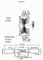
- the local deformation was detected by means of a conventional strain gage (RS 5mm Wire Lead Strain, gauge factor 2.1) bonded to one side of the specimen and having a gauge resistance of 120 ⁇ constantly measured with a precision multimeter HP 34401A.
- Copper electrodes were fixed on the sample surface using silver paint (Silver Conductive Paint, resistivity of 0.001 ⁇ cm) thus ensuring a good ohmic contact between the parts for the measurement of the resistance, R, of the samples using the two-probe method with a Multimeter Keithley 6517A configured in the double function of voltage generator and ammeter.
- This measurement method although simple, has successfully been applied in literature for resistance measurements in presence of tensile test. Contact resistance was neglected since the measured electrical resistance for all specimens was in the order of several k ⁇ .
- the same electrodes were used for the impedance spectroscopy (IS) analysis performed with a precision LCR meter (model QuadTech 7600).
- the strain sensing properties of the nanocomposites depend on the intrinsic response of the constituent materials (i.e., resin and MWCNTs) and on their mutual interactions which are governed by the interfacial properties.
- the distribution of the filler within the resin which determines the electrical percolation network and the formation of conductive junctions (i.e., CJ) due to the tunneling effect between neighbor tubes, can be highlighted by means of scanning electron microscopy (SEM) of a fractured surface of a nanocomposite, as shown in Fig.3 .
- SEM scanning electron microscopy
- the piezoresistivity behavior observed in the strain sensors based on CNT/polymer nanocomposites is attributable to relevant changes in the electrical network, e.g.
- ⁇ c is the amount corresponding to percolation threshold
- ⁇ 0 is the filler conductivity
- t an exponent depending on the system dimensionality.
- conductive paths are formed in the composite when the CNT amount (i.e. ⁇ ) increases over a threshold value (EPT, i.e. ⁇ c ) thus leading the material to convert from an insulating to a conductive behavior.
- EPT i.e. ⁇ c
- the sensitivity of the composites reinforced with carbon-base filler is low when the composite acts as an insulator (below the EPT) and decreases significantly as the weight loading of CNTs increases in the high conductivity region. Therefore, the region around the EPT is the most suitable for sensor applications.
- the mechanical and piezoresistive tensile response of an epoxy resin suitable for the realization of structural aeronautic components and reinforced with 0.3 wt.% of multi-walled carbon nanotubes (MWCNTs) was investigated, when specimens are subjected to a low number of fatigue cycles in axial and flexural mode.
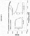
- Fig. 5 shows the plot of magnitude of the overall impedance of material (in ⁇ ) and in the inset the relative phase angle (in degree) and real part of the dielectric permittivity (i.e. ⁇ r ) respectively, as a function of the frequency.
- the variations of the real part of the dielectric permittivity vs. frequency can be ascribed to the presence of free dipolar functional groups (mainly of type C-OH or sometimes N-H as reaction product) and more significantly to interfacial polarization attributable to the presence of conducting impurities.
- free dipolar functional groups mainly of type C-OH or sometimes N-H as reaction product
- interfacial polarization attributable to the presence of conducting impurities.
- the system shows the highest value and, as the frequency increases, the permittivity progressively decreases because both mechanisms become negligible.
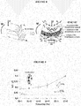
- the left diagram of figure 6 shows the mechanical and piezoresistive performances of the epoxy-based composites reinforced with 0.3 wt.% of MWCNTs when loaded in axial tension up to failure.
- the mechanical loading i.e. ⁇
- ⁇ is also plotted on the left vertical axis. A direct relationship between the two plotted parameters can be observed.
- the ⁇ R/R 0 curve becomes nonlinear with an evident abrupt change most likely due to the occurrence of the first nano-crackings within the structure.
- the value obtained of 0.43 is derived as the slope of the interpolating line of ⁇ R/R 0 curve of experimental data that lie in the elastic region.
- specimens were subjected to tensile loading cycles based on increases/decreases of some selected level strains. As shown in the right diagram of figure 6 , increasing strain per cycle was applied (i.e. 0.83%, 1.65% and 2.42%), and the temporal behavior of the piezoresistive response was monitored.
- the presence of a residual resistance appears due to some damage in the sensor most likely as a result of a permanent and irreversible phenomena (yielding) in electrical percolating network associated to morphological rearrangement of the CNTs dispersed in the polymer resin and to the fatigue and plastic deformation of the latter. Therefore, in plastic regime the sensor system may allow the detection of possible damages in the monitored part.
- the change of electrical resistance was also correlated to bending deformations.
- Other literature studies report experiments performed in the 4-points-bending mode where the strain was calculated from the theory of pure bending of a plate due to a cylinder surface, valid between the inner loadings points.
- the flexural stress-strain curves are obtained from three point bend test of the samples. The obtained results are shown in the left diagram of figure 7 .
- the flexural strain was detected by means of a conventional strain gauge.
- the electrical response of the material is influenced by a combination of two coexisting dynamic effects.
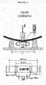
- some parts (those above the neutral plane, i.e. n p ) of resin, which acts as an insulating spacer between the conductive particles, will shorten due to the action of the internal compressive stresses (i.e. ⁇ c ) and other (those below the neutral plane) will lengthen due to internal tensile stresses (i.e. ⁇ t ), as shown in Fig.8 .
- the elongation of resin in the convex part will predominate over the compression of the same in the concave part.
- the tunneling resistance between nanotubes affects more significantly the electrical response of the material thus originating the exponential dependence of the ⁇ R/R 0 vs. strain.
- the piezoresistive effect of the material affects more significantly the electrical response of the material thus originating the exponential dependence of the ⁇ R/R 0 vs. strain.
- the sensitivity of the composites evaluated with DC measurements has been also compared with that obtained by impedance analysis, in order to evaluate a possible contribution of the dielectric properties on sensing performances.
- the impedance of the sample starting from the frequency of 100 kHz was found to be dispersive (frequency dependent) due to capacitive effects that start to become dominant over those associated to the conduction, thereby influencing the macroscopic AC properties of the composites.
- the G.F. improves significantly as the frequency increases and in particular the most favorable value is observed at 1MHz where G.F. is 0.60, about 40% higher than that estimated in DC.
- This improvement in the sensitivity may be attributed to a synergy between the capacitive and resistive effects that coexist in a composite system with an insulating matrix filled with a conductive phase and that can magnify the response of the sensor.
- the AC properties of the polymer/carbon based composites can be analyzed by using a single-time-constant equivalent circuit model (i.e. STC circuit ) whose overall impedance is given by the parallel combination of a resistor (i.e. Rp ) and capacitor (i.e. Cp ) as shown in the equivalent circuit of figure 10 .
- the tunneling resistance increases with the particle separation up to of a cut-off distance (about 2 nm); unlikely, the capacitance decreases as the particle distance increases.
- the changes in the values of resistances and capacitances of the sensor under different level of strain are analyzed at the frequency of 1 MHZ and the results are shown in Fig. 11 .
- the left diagram of figure 12 shows the mechanical and piezoresistive response of the nanocomposites measured at operating frequency of 1MHz when strain that falls in the elastic regime of the material is applied in order to evaluate the gauge factor.
- the results concern the normalized change of electrical impedance ⁇ Z/Z 0 (right vertical axis), and that of mechanical loading (i.e. ⁇ , left vertical axis) plotted against the axial strain ( ⁇ ). It is possible to observe that ⁇ Z/Z 0 increases linearly as a function of the tensile strain with ⁇ Z/Z 0 ⁇ k ⁇ where k, coincident with the G.F. (i.e.
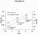
- Figure 13 shows the experimental results concerning the piezoresistive response of the material, in terms of impedance changing ratio, when subjected to bending loads, evaluated at different operating frequency.
- the electrical response of the sample is regular since the impedance variations, at the same value of the strain, exhibits comparable values (%) in the ratio ⁇ Z/Z 0 . Furthermore, the electrical response follows linearly the mechanical deformation, both during the loading and the unloading phases. Since the deformation loads are limited in the elastic regime of the material (about 2%), ⁇ Z/Z 0 returns to the initial value after each loading cycles thus indicating that the applied strain induces reversible variations in the nanotube network configuration.
- the resistance and impedance change ratios are compared for each level of strain in terms of average of the maximum value measured in each cycle.
Applications Claiming Priority (1)
| Application Number | Priority Date | Filing Date | Title |
|---|---|---|---|
| ITUA2016A002902A ITUA20162902A1 (it) | 2016-04-27 | 2016-04-27 | Metodo di monitoraggio di un materiale composito. |
Publications (1)
| Publication Number | Publication Date |
|---|---|
| EP3242128A1 true EP3242128A1 (de) | 2017-11-08 |
Family
ID=56555620
Family Applications (1)
| Application Number | Title | Priority Date | Filing Date |
|---|---|---|---|
| EP17167744.6A Pending EP3242128A1 (de) | 2016-04-27 | 2017-04-24 | Verfahren zur überwachung eines verbundwerkstoffs |
Country Status (3)
| Country | Link |
|---|---|
| US (1) | US10196153B2 (de) |
| EP (1) | EP3242128A1 (de) |
| IT (1) | ITUA20162902A1 (de) |
Families Citing this family (5)
| Publication number | Priority date | Publication date | Assignee | Title |
|---|---|---|---|---|
| JP6803352B2 (ja) * | 2018-03-15 | 2020-12-23 | 株式会社Subaru | 飛行制限設定システム、飛行制限設定方法及び飛行制限設定プログラム |
| KR102578194B1 (ko) * | 2018-06-20 | 2023-09-13 | 현대자동차주식회사 | 자동차의 손상 검출 장치 및 방법 |
| CN110146550B (zh) * | 2019-06-13 | 2020-03-13 | 南京航空航天大学 | 基于电阻抗成像的复合材料高温部件氧化程度监测方法 |
| CN112989596B (zh) * | 2021-03-09 | 2022-03-01 | 天津大学 | 基于驱动能量的机械应力作用下电树枝劣化分析方法 |
| CN113587836A (zh) * | 2021-07-30 | 2021-11-02 | 中国计量大学 | 一种光纤光栅应变传感器的原位校准方法 |
Citations (5)
| Publication number | Priority date | Publication date | Assignee | Title |
|---|---|---|---|---|
| CA2570117A1 (en) * | 2004-06-25 | 2006-01-12 | University Of Dayton | Sensing system for monitoring the structural health of composite structures |
| CA2766486A1 (en) * | 2009-01-16 | 2010-07-29 | The Board Of Regents Of The University Of Oklahoma | Sensor-enabled geosynthetic material and method of making and using the same |
| US20110142091A1 (en) * | 2008-05-20 | 2011-06-16 | Massachusetts Institute of Techonology | Systems and methods for structural sensing |
| US8384398B2 (en) | 2010-03-31 | 2013-02-26 | Massachusetts Institute Of Technology | Structural health monitoring system and method using soft capacitive sensing materials |
| US20130312535A1 (en) | 2010-09-20 | 2013-11-28 | Bae Systems Plc | Structural health monitoring using sprayable paint formulations |
Family Cites Families (5)
| Publication number | Priority date | Publication date | Assignee | Title |
|---|---|---|---|---|
| US7786736B2 (en) * | 2003-08-06 | 2010-08-31 | University Of Delaware | Method and system for detecting damage in aligned carbon nanotube fiber composites using networks |
| US7908928B2 (en) * | 2006-10-31 | 2011-03-22 | Caterpillar Inc. | Monitoring system |
| US20080231294A1 (en) * | 2007-03-19 | 2008-09-25 | Ndsu Research Foundation | Structural health monitoring circuit |
| US8250927B2 (en) * | 2010-03-17 | 2012-08-28 | Indian Institute Of Science | Flexible, stretchable, and distributed strain sensors |
| KR20130118582A (ko) * | 2012-04-20 | 2013-10-30 | 삼성에스디아이 주식회사 | 연료 전지용 전극, 이의 제조 방법, 이를 포함하는 연료 전지용 막-전극 어셈블리, 이를 포함하는 연료 전지 시스템 |
-
2016
- 2016-04-27 IT ITUA2016A002902A patent/ITUA20162902A1/it unknown
-
2017
- 2017-04-24 EP EP17167744.6A patent/EP3242128A1/de active Pending
- 2017-04-25 US US15/496,367 patent/US10196153B2/en not_active Expired - Fee Related
Patent Citations (6)
| Publication number | Priority date | Publication date | Assignee | Title |
|---|---|---|---|---|
| CA2570117A1 (en) * | 2004-06-25 | 2006-01-12 | University Of Dayton | Sensing system for monitoring the structural health of composite structures |
| CA2570117C (en) | 2004-06-25 | 2014-01-21 | University Of Dayton | Sensing system for monitoring the structural health of composite structures |
| US20110142091A1 (en) * | 2008-05-20 | 2011-06-16 | Massachusetts Institute of Techonology | Systems and methods for structural sensing |
| CA2766486A1 (en) * | 2009-01-16 | 2010-07-29 | The Board Of Regents Of The University Of Oklahoma | Sensor-enabled geosynthetic material and method of making and using the same |
| US8384398B2 (en) | 2010-03-31 | 2013-02-26 | Massachusetts Institute Of Technology | Structural health monitoring system and method using soft capacitive sensing materials |
| US20130312535A1 (en) | 2010-09-20 | 2013-11-28 | Bae Systems Plc | Structural health monitoring using sprayable paint formulations |
Non-Patent Citations (1)
| Title |
|---|
| M. POUR-GHAZ, J. WEISS: "Detecting the time and location of cracks using electrically conductive surfaces", CEMENT & CONCRETE COMPOSITES, vol. 33, 2010, pages 116 - 123, XP002774142 * |
Also Published As
| Publication number | Publication date |
|---|---|
| US10196153B2 (en) | 2019-02-05 |
| ITUA20162902A1 (it) | 2017-10-27 |
| US20170313436A1 (en) | 2017-11-02 |
Similar Documents
| Publication | Publication Date | Title |
|---|---|---|
| Vertuccio et al. | Piezoresistive properties of resin reinforced with carbon nanotubes for health-monitoring of aircraft primary structures | |
| US10196153B2 (en) | Method of monitoring a composite material | |
| Spinelli et al. | Experimental and theoretical study on piezoresistive properties of a structural resin reinforced with carbon nanotubes for strain sensing and damage monitoring | |
| Vertuccio et al. | Strain and damage monitoring in carbon-nanotube-based composite under cyclic strain | |
| Moriche et al. | Strain monitoring mechanisms of sensors based on the addition of graphene nanoplatelets into an epoxy matrix | |
| Wang et al. | Properties and mechanisms of self-sensing carbon nanofibers/epoxy composites for structural health monitoring | |
| Georgousis et al. | Strain sensing in polymer/carbon nanotube composites by electrical resistance measurement | |
| Wichmann et al. | Piezoresistive response of epoxy composites with carbon nanoparticles under tensile load | |
| Kostopoulos et al. | Damage monitoring of carbon fiber reinforced laminates using resistance measurements. Improving sensitivity using carbon nanotube doped epoxy matrix system | |
| Wang et al. | Piezoresistive effect of a carbon nanotube silicone-matrix composite | |
| Grammatikos et al. | On the electrical properties of multi scale reinforced composites for damage accumulation monitoring | |
| Monti et al. | Carbon nanofibers for strain and impact damage sensing in glass fiber reinforced composites based on an unsaturated polyester resin | |
| Baltopoulos et al. | Sensing strain and damage in polyurethane-MWCNT nano-composite foams using electrical measurements. | |
| Monti et al. | Impact damage sensing in glass fiber reinforced composites based on carbon nanotubes by electrical resistance measurements | |
| Koecher et al. | Piezoresistive in-situ strain sensing of composite laminate structures | |
| Sánchez-Romate et al. | Highly sensitive strain gauges with carbon nanotubes: From bulk nanocomposites to multifunctional coatings for damage sensing | |
| D’Alessandro et al. | Stainless steel microfibers for strain-sensing smart clay bricks | |
| Fernandez Sanchez-Romate et al. | Carbon nanotube-doped adhesive films for detecting crack propagation on bonded joints: a deeper understanding of anomalous behaviors | |
| Al-Bahrani et al. | Micro-scale damage sensing in self-sensing nanocomposite material based CNTs | |
| Beutier et al. | In-situ coupled mechanical/electrical investigations of EPDM/CB composite materials: The electrical signature of the mechanical Mullins effect | |
| Stetco et al. | Piezocapacitive sensing for structural health monitoring in adhesive joints | |
| Esmaeili et al. | Piezoresistive characterization of epoxy based nanocomposites loaded with SWCNTs‐DWCNTs in tensile and fracture tests | |
| Sam-Daliri et al. | Condition monitoring of crack extension in the reinforced adhesive joint by carbon nanotubes | |
| JP5605559B2 (ja) | 金属表面処理を施したナノフィラーからなる高感度ひずみセンサ | |
| Materazzi et al. | Carbon nanotube cement-based sensors for dynamic monitoring of concrete structures |
Legal Events
| Date | Code | Title | Description |
|---|---|---|---|
| PUAI | Public reference made under article 153(3) epc to a published international application that has entered the european phase |
Free format text: ORIGINAL CODE: 0009012 |
|
| STAA | Information on the status of an ep patent application or granted ep patent |
Free format text: STATUS: THE APPLICATION HAS BEEN PUBLISHED |
|
| AK | Designated contracting states |
Kind code of ref document: A1 Designated state(s): AL AT BE BG CH CY CZ DE DK EE ES FI FR GB GR HR HU IE IS IT LI LT LU LV MC MK MT NL NO PL PT RO RS SE SI SK SM TR |
|
| AX | Request for extension of the european patent |
Extension state: BA ME |
|
| STAA | Information on the status of an ep patent application or granted ep patent |
Free format text: STATUS: REQUEST FOR EXAMINATION WAS MADE |
|
| 17P | Request for examination filed |
Effective date: 20180507 |
|
| RBV | Designated contracting states (corrected) |
Designated state(s): AL AT BE BG CH CY CZ DE DK EE ES FI FR GB GR HR HU IE IS IT LI LT LU LV MC MK MT NL NO PL PT RO RS SE SI SK SM TR |
|
| STAA | Information on the status of an ep patent application or granted ep patent |
Free format text: STATUS: EXAMINATION IS IN PROGRESS |
|
| 17Q | First examination report despatched |
Effective date: 20200219 |
|
| STAA | Information on the status of an ep patent application or granted ep patent |
Free format text: STATUS: EXAMINATION IS IN PROGRESS |
|
| STAA | Information on the status of an ep patent application or granted ep patent |
Free format text: STATUS: EXAMINATION IS IN PROGRESS |