EP3242105A1 - Heat temperature gradient heat exchanger - Google Patents
Heat temperature gradient heat exchanger Download PDFInfo
- Publication number
- EP3242105A1 EP3242105A1 EP17169955.6A EP17169955A EP3242105A1 EP 3242105 A1 EP3242105 A1 EP 3242105A1 EP 17169955 A EP17169955 A EP 17169955A EP 3242105 A1 EP3242105 A1 EP 3242105A1
- Authority
- EP
- European Patent Office
- Prior art keywords
- airflow
- manifold
- heat exchanger
- exchanger assembly
- recited
- Prior art date
- Legal status (The legal status is an assumption and is not a legal conclusion. Google has not performed a legal analysis and makes no representation as to the accuracy of the status listed.)
- Granted
Links
Images



Classifications
-
- F—MECHANICAL ENGINEERING; LIGHTING; HEATING; WEAPONS; BLASTING
- F02—COMBUSTION ENGINES; HOT-GAS OR COMBUSTION-PRODUCT ENGINE PLANTS
- F02C—GAS-TURBINE PLANTS; AIR INTAKES FOR JET-PROPULSION PLANTS; CONTROLLING FUEL SUPPLY IN AIR-BREATHING JET-PROPULSION PLANTS
- F02C7/00—Features, components parts, details or accessories, not provided for in, or of interest apart form groups F02C1/00 - F02C6/00; Air intakes for jet-propulsion plants
- F02C7/12—Cooling of plants
- F02C7/16—Cooling of plants characterised by cooling medium
- F02C7/18—Cooling of plants characterised by cooling medium the medium being gaseous, e.g. air
-
- F—MECHANICAL ENGINEERING; LIGHTING; HEATING; WEAPONS; BLASTING
- F02—COMBUSTION ENGINES; HOT-GAS OR COMBUSTION-PRODUCT ENGINE PLANTS
- F02C—GAS-TURBINE PLANTS; AIR INTAKES FOR JET-PROPULSION PLANTS; CONTROLLING FUEL SUPPLY IN AIR-BREATHING JET-PROPULSION PLANTS
- F02C6/00—Plural gas-turbine plants; Combinations of gas-turbine plants with other apparatus; Adaptations of gas-turbine plants for special use
- F02C6/04—Gas-turbine plants providing heated or pressurised working fluid for other apparatus, e.g. without mechanical power output
- F02C6/06—Gas-turbine plants providing heated or pressurised working fluid for other apparatus, e.g. without mechanical power output providing compressed gas
- F02C6/08—Gas-turbine plants providing heated or pressurised working fluid for other apparatus, e.g. without mechanical power output providing compressed gas the gas being bled from the gas-turbine compressor
-
- F—MECHANICAL ENGINEERING; LIGHTING; HEATING; WEAPONS; BLASTING
- F02—COMBUSTION ENGINES; HOT-GAS OR COMBUSTION-PRODUCT ENGINE PLANTS
- F02C—GAS-TURBINE PLANTS; AIR INTAKES FOR JET-PROPULSION PLANTS; CONTROLLING FUEL SUPPLY IN AIR-BREATHING JET-PROPULSION PLANTS
- F02C3/00—Gas-turbine plants characterised by the use of combustion products as the working fluid
- F02C3/04—Gas-turbine plants characterised by the use of combustion products as the working fluid having a turbine driving a compressor
-
- F—MECHANICAL ENGINEERING; LIGHTING; HEATING; WEAPONS; BLASTING
- F02—COMBUSTION ENGINES; HOT-GAS OR COMBUSTION-PRODUCT ENGINE PLANTS
- F02C—GAS-TURBINE PLANTS; AIR INTAKES FOR JET-PROPULSION PLANTS; CONTROLLING FUEL SUPPLY IN AIR-BREATHING JET-PROPULSION PLANTS
- F02C7/00—Features, components parts, details or accessories, not provided for in, or of interest apart form groups F02C1/00 - F02C6/00; Air intakes for jet-propulsion plants
- F02C7/12—Cooling of plants
- F02C7/16—Cooling of plants characterised by cooling medium
- F02C7/18—Cooling of plants characterised by cooling medium the medium being gaseous, e.g. air
- F02C7/185—Cooling means for reducing the temperature of the cooling air or gas
-
- F—MECHANICAL ENGINEERING; LIGHTING; HEATING; WEAPONS; BLASTING
- F02—COMBUSTION ENGINES; HOT-GAS OR COMBUSTION-PRODUCT ENGINE PLANTS
- F02C—GAS-TURBINE PLANTS; AIR INTAKES FOR JET-PROPULSION PLANTS; CONTROLLING FUEL SUPPLY IN AIR-BREATHING JET-PROPULSION PLANTS
- F02C9/00—Controlling gas-turbine plants; Controlling fuel supply in air- breathing jet-propulsion plants
- F02C9/16—Control of working fluid flow
- F02C9/18—Control of working fluid flow by bleeding, bypassing or acting on variable working fluid interconnections between turbines or compressors or their stages
-
- F—MECHANICAL ENGINEERING; LIGHTING; HEATING; WEAPONS; BLASTING
- F02—COMBUSTION ENGINES; HOT-GAS OR COMBUSTION-PRODUCT ENGINE PLANTS
- F02K—JET-PROPULSION PLANTS
- F02K3/00—Plants including a gas turbine driving a compressor or a ducted fan
- F02K3/08—Plants including a gas turbine driving a compressor or a ducted fan with supplementary heating of the working fluid; Control thereof
- F02K3/105—Heating the by-pass flow
- F02K3/115—Heating the by-pass flow by means of indirect heat exchange
-
- F—MECHANICAL ENGINEERING; LIGHTING; HEATING; WEAPONS; BLASTING
- F28—HEAT EXCHANGE IN GENERAL
- F28F—DETAILS OF HEAT-EXCHANGE AND HEAT-TRANSFER APPARATUS, OF GENERAL APPLICATION
- F28F9/00—Casings; Header boxes; Auxiliary supports for elements; Auxiliary members within casings
- F28F9/02—Header boxes; End plates
- F28F9/026—Header boxes; End plates with static flow control means, e.g. with means for uniformly distributing heat exchange media into conduits
- F28F9/0278—Header boxes; End plates with static flow control means, e.g. with means for uniformly distributing heat exchange media into conduits in the form of stacked distribution plates or perforated plates arranged over end plates
-
- F—MECHANICAL ENGINEERING; LIGHTING; HEATING; WEAPONS; BLASTING
- F05—INDEXING SCHEMES RELATING TO ENGINES OR PUMPS IN VARIOUS SUBCLASSES OF CLASSES F01-F04
- F05D—INDEXING SCHEME FOR ASPECTS RELATING TO NON-POSITIVE-DISPLACEMENT MACHINES OR ENGINES, GAS-TURBINES OR JET-PROPULSION PLANTS
- F05D2220/00—Application
- F05D2220/30—Application in turbines
- F05D2220/32—Application in turbines in gas turbines
-
- F—MECHANICAL ENGINEERING; LIGHTING; HEATING; WEAPONS; BLASTING
- F05—INDEXING SCHEMES RELATING TO ENGINES OR PUMPS IN VARIOUS SUBCLASSES OF CLASSES F01-F04
- F05D—INDEXING SCHEME FOR ASPECTS RELATING TO NON-POSITIVE-DISPLACEMENT MACHINES OR ENGINES, GAS-TURBINES OR JET-PROPULSION PLANTS
- F05D2260/00—Function
- F05D2260/20—Heat transfer, e.g. cooling
-
- F—MECHANICAL ENGINEERING; LIGHTING; HEATING; WEAPONS; BLASTING
- F05—INDEXING SCHEMES RELATING TO ENGINES OR PUMPS IN VARIOUS SUBCLASSES OF CLASSES F01-F04
- F05D—INDEXING SCHEME FOR ASPECTS RELATING TO NON-POSITIVE-DISPLACEMENT MACHINES OR ENGINES, GAS-TURBINES OR JET-PROPULSION PLANTS
- F05D2260/00—Function
- F05D2260/20—Heat transfer, e.g. cooling
- F05D2260/213—Heat transfer, e.g. cooling by the provision of a heat exchanger within the cooling circuit
-
- F—MECHANICAL ENGINEERING; LIGHTING; HEATING; WEAPONS; BLASTING
- F28—HEAT EXCHANGE IN GENERAL
- F28D—HEAT-EXCHANGE APPARATUS, NOT PROVIDED FOR IN ANOTHER SUBCLASS, IN WHICH THE HEAT-EXCHANGE MEDIA DO NOT COME INTO DIRECT CONTACT
- F28D21/00—Heat-exchange apparatus not covered by any of the groups F28D1/00 - F28D20/00
- F28D2021/0019—Other heat exchangers for particular applications; Heat exchange systems not otherwise provided for
- F28D2021/0021—Other heat exchangers for particular applications; Heat exchange systems not otherwise provided for for aircrafts or cosmonautics
-
- F—MECHANICAL ENGINEERING; LIGHTING; HEATING; WEAPONS; BLASTING
- F28—HEAT EXCHANGE IN GENERAL
- F28D—HEAT-EXCHANGE APPARATUS, NOT PROVIDED FOR IN ANOTHER SUBCLASS, IN WHICH THE HEAT-EXCHANGE MEDIA DO NOT COME INTO DIRECT CONTACT
- F28D21/00—Heat-exchange apparatus not covered by any of the groups F28D1/00 - F28D20/00
- F28D2021/0019—Other heat exchangers for particular applications; Heat exchange systems not otherwise provided for
- F28D2021/0026—Other heat exchangers for particular applications; Heat exchange systems not otherwise provided for for combustion engines, e.g. for gas turbines or for Stirling engines
-
- F—MECHANICAL ENGINEERING; LIGHTING; HEATING; WEAPONS; BLASTING
- F28—HEAT EXCHANGE IN GENERAL
- F28F—DETAILS OF HEAT-EXCHANGE AND HEAT-TRANSFER APPARATUS, OF GENERAL APPLICATION
- F28F2270/00—Thermal insulation; Thermal decoupling
-
- Y—GENERAL TAGGING OF NEW TECHNOLOGICAL DEVELOPMENTS; GENERAL TAGGING OF CROSS-SECTIONAL TECHNOLOGIES SPANNING OVER SEVERAL SECTIONS OF THE IPC; TECHNICAL SUBJECTS COVERED BY FORMER USPC CROSS-REFERENCE ART COLLECTIONS [XRACs] AND DIGESTS
- Y02—TECHNOLOGIES OR APPLICATIONS FOR MITIGATION OR ADAPTATION AGAINST CLIMATE CHANGE
- Y02T—CLIMATE CHANGE MITIGATION TECHNOLOGIES RELATED TO TRANSPORTATION
- Y02T50/00—Aeronautics or air transport
- Y02T50/60—Efficient propulsion technologies, e.g. for aircraft
Definitions
- a gas turbine engine typically includes a fan section, a compressor section, a combustor section and a turbine section. Air entering the compressor section is compressed and delivered into the combustion section where it is mixed with fuel and ignited to generate a high-energy exhaust gas flow. The high-energy exhaust gas flow expands through the turbine section to drive the compressor and the fan section.
- Cooling airflow is drawn from the compressor section and may be further cooled utilizing heat exchangers to provide increased cooling capacity.
- Higher engine operating temperatures and pressures challenge the capacities of heat exchangers fabricated utilizing conventional materials and configurations.
- a heat exchanger assembly in one aspect, includes an outer manifold defining an outer cavity.
- An inner cavity is defined by an inner shell supported within the outer manifold and at least partially surrounded by the outer cavity.
- the inner shell includes a plurality of impingement openings for directing airflow into the inner cavity.
- An inner manifold is supported within the inner cavity.
- the inner manifold is exposed to impingement airflow through the plurality of impingement openings in the inner shell.
- the inner manifold includes a plurality of flow passages and at least one insulator pocket substantially aligned with the plurality of flow passages.
- the inner shell includes at least two fingers supporting the inner manifold.
- the at least two fingers are compliant to accommodate thermal expansion of the inner manifold.
- Another embodiment according to any of the previous embodiments includes at least one opening for airflow in each of the at least two fingers.
- the outer manifold defines an inlet into the outer cavity, and the inner cavity is open at opposing first and second ends transverse to the direction of impingement flow.
- Another embodiment according to any of the previous embodiments includes at least two insulator pockets disposed between each of the plurality of flow passages.
- the at least one insulator pocket is closed to airflow.
- each of the plurality of passages includes a length substantially aligned with cooling airflow from the plurality of impingement openings.
- the length of each of the plurality of passages is greater than a width transverse to the direction of the cooling airflow from the plurality of impingement openings.
- each of the plurality of passages includes a midpoint between a first end and a second end and a width at the midpoint is greater than a width at each of the first end and the second end.
- an outer surface of the inner manifold includes peaks corresponding to the first end and the second end separated by valleys.
- a cooled cooling air system for a gas turbine engine includes a first source of airflow at a first pressure and temperature and a second source of airflow at a second pressure and temperature. The second temperature and pressure is less than the first temperature and pressure.
- a heat exchanger assembly includes an outer manifold defining an outer cavity and a cold inlet in communication with airflow from the second source.
- An inner shell defines an inner cavity. The inner shell is supported within the outer manifold and at least partially surrounded by the outer cavity.
- the inner shell includes a plurality of impingement openings for directing airflow from the outer manifold into the inner cavity.
- An inner manifold is supported within the inner cavity and a hot inlet in communication with airflow from the first source. The inner manifold is exposed to impingement airflow through the plurality of impingement openings in the inner shell.
- the inner manifold includes a plurality of flow passages and at least one insulator pocket substantially aligned with the plurality of flow passages.
- the inner shell includes at least two fingers supporting the inner manifold.
- the at least two fingers are compliant to accommodate thermal expansion of the inner manifold.
- the inner cavity is open at opposing first and second ends transverse to a direction of impingement flow.
- the at least one insulator pocket is closed to airflow.
- each of the plurality of passages includes a length substantially aligned with cooling airflow from the plurality of impingement openings.
- the length of each of the plurality of passages is greater than a width transverse to the direction of the cooling airflow from the plurality of impingement openings.
- a gas turbine engine assembly in another aspect, includes a compressor section including a bleed air opening for a first source of airflow at a first pressure and first temperature and a second source of airflow at a second pressure and a second temperature.
- a heat exchanger assembly includes an outer manifold defining an outer cavity and a cold inlet in communication with airflow from the second source.
- An inner shell defines an inner cavity. The inner shell is supported within the outer manifold and at least partially surrounded by the outer cavity. The inner shell includes a plurality of impingement openings for directing airflow from the outer manifold into the inner cavity.
- An inner manifold is supported within the inner cavity and a hot inlet in communication with airflow from the first source.
- the inner manifold is exposed to impingement airflow through the plurality of impingement openings in the inner shell.
- the inner manifold includes a plurality of flow passages and at least one insulator pocket substantially aligned with the plurality of flow passages.
- a turbine section includes at least one cooling air passage receiving cooled airflow from an outlet of the inner manifold.
- the inner shell includes at least two fingers supporting the inner manifold.
- the at least two fingers are compliant to accommodate thermal expansion of the inner manifold.
- the inner cavity is open at opposing first and second ends transverse to a direction of impingement flow.
- the at least one insulator pocket is closed to airflow.
- each of the plurality of passages includes a length substantially aligned with cooling airflow from the plurality of impingement openings.
- the length of each of the plurality of passages is greater than a width transverse to the direction of the cooling airflow from the plurality of impingement openings.
- FIG. 1 schematically illustrates an example gas turbine engine 20 that includes a fan section 22, a compressor section 24, a combustor section 26 and a turbine section 28.
- Alternative engines might include an augmenter section (not shown) among other systems or features.
- the fan section 22 drives air along a bypass flow path B while the compressor section 24 draws air in along a core flow path C where air is compressed and communicated to a combustor section 26.
- air is mixed with fuel and ignited to generate a high energy exhaust gas stream that expands through the turbine section 28 where energy is extracted and utilized to drive the fan section 22 and the compressor section 24.
- a turbine engine including a three-spool architecture in which three spools concentrically rotate about a common axis and where a low spool enables a low pressure turbine to drive a fan via a gearbox, an intermediate spool that enables an intermediate pressure turbine to drive a first compressor of the compressor section, and a high spool that enables a high pressure turbine to drive a high pressure compressor of the compressor section.
- the example engine 20 generally includes a low speed spool 30 and a high speed spool 32 mounted for rotation about an engine central longitudinal axis A relative to an engine static structure 36 via several bearing systems 38. It should be understood that various bearing systems 38 at various locations may alternatively or additionally be provided.
- the low speed spool 30 generally includes an inner shaft 40 that connects a fan 42 and a low pressure (or first) compressor section 44 to a low pressure (or first) turbine section 46.
- the inner shaft 40 drives the fan 42 through a speed change device, such as a geared architecture 48, to drive the fan 42 at a lower speed than the low speed spool 30.
- the high-speed spool 32 includes an outer shaft 50 that interconnects a high pressure (or second) compressor section 52 and a high pressure (or second) turbine section 54.
- the inner shaft 40 and the outer shaft 50 are concentric and rotate via the bearing systems 38 about the engine central longitudinal axis A.
- a combustor 56 is arranged between the high pressure compressor 52 and the high pressure turbine 54.
- the high pressure turbine 54 includes at least two stages to provide a double stage high pressure turbine 54.
- the high pressure turbine 54 includes only a single stage.
- a "high pressure" compressor or turbine experiences a higher pressure than a corresponding "low pressure” compressor or turbine.
- the example low pressure turbine 46 has a pressure ratio that is greater than about 5.
- the pressure ratio of the example low pressure turbine 46 is measured prior to an inlet of the low pressure turbine 46 as related to the pressure measured at the outlet of the low pressure turbine 46 prior to an exhaust nozzle.
- a mid-turbine frame 58 of the engine static structure 36 is arranged generally between the high pressure turbine 54 and the low pressure turbine 46.
- the mid-turbine frame 58 further supports bearing systems 38 in the turbine section 28 as well as setting airflow entering the low pressure turbine 46.
- Airflow through the core airflow path C is compressed by the low pressure compressor 44 then by the high pressure compressor 52 mixed with fuel and ignited in the combustor 56 to produce high energy exhaust gases that are then expanded through the high pressure turbine 54 and low pressure turbine 46.
- the mid-turbine frame 58 includes vanes 60, which are in the core airflow path and function as an inlet guide vane for the low pressure turbine 46. Utilizing the vane 60 of the mid-turbine frame 58 as the inlet guide vane for low pressure turbine 46 decreases the length of the low pressure turbine 46 without increasing the axial length of the mid-turbine frame 58. Reducing or eliminating the number of vanes in the low pressure turbine 46 shortens the axial length of the turbine section 28. Thus, the compactness of the gas turbine engine 20 is increased and a higher power density may be achieved.
- the disclosed gas turbine engine 20 in one example is a high-bypass geared aircraft engine.
- the gas turbine engine 20 includes a bypass ratio greater than about six, with an example embodiment being greater than about ten.
- the example geared architecture 48 is an epicyclical gear train, such as a planetary gear system, star gear system or other known gear system, with a gear reduction ratio of greater than about 2.3.
- the gas turbine engine 20 includes a bypass ratio greater than about ten and the fan diameter is significantly larger than an outer diameter of the low pressure compressor 44. It should be understood, however, that the above parameters are only exemplary of one embodiment of a gas turbine engine including a geared architecture and that the present disclosure is applicable to other gas turbine engines.
- the fan section 22 of the engine 20 is designed for a particular flight condition -- typically cruise at about 0.8 Mach and about 35,000 feet (10,668 m).
- the flight condition of 0.8 Mach and 35,000 ft. (10,668 m), with the engine at its best fuel consumption - also known as "bucket cruise Thrust Specific Fuel Consumption ('TSFC')" - is the industry standard parameter of pound-mass (lbm) of fuel per hour being burned divided by pound-force (lbf) of thrust the engine produces at that minimum point.
- Low fan pressure ratio is the pressure ratio across the fan blade alone, without a Fan Exit Guide Vane (“FEGV”) system.
- the low fan pressure ratio as disclosed herein according to one non-limiting embodiment is less than about 1.50. In another non-limiting embodiment the low fan pressure ratio is less than about 1.45.
- the "Low corrected fan tip speed”, as disclosed herein according to one non-limiting embodiment, is less than about 1150 ft/second (350.5 m/s).
- the example gas turbine engine includes the fan 42 that comprises in one non-limiting embodiment less than about twenty-six fan blades. In another non-limiting embodiment, the fan section 22 includes less than about twenty fan blades. Moreover, in one disclosed embodiment the low pressure turbine 46 includes no more than about six turbine rotor schematically indicated at 34. In another non-limiting example embodiment the low pressure turbine 46 includes about three turbine rotors. A ratio between the number of fan blades 42 and the number of low pressure turbine rotors is between about 3.3 and about 8.6. The example low pressure turbine 46 provides the driving power to rotate the fan section 22 and therefore the relationship between the number of turbine rotors 34 in the low pressure turbine 46 and the number of blades 42 in the fan section 22 disclose an example gas turbine engine 20 with increased power transfer efficiency.
- the example engine 20 includes a cooled cooling air system (CCA) 62 that receives air from an outlet 94 within the compressor section 24. Air from the outlet 94 is at a first temperature T1 and a first pressure P1. Bypass air 66 at a second temperature T2 and second pressure P2 is fed through a heat exchange 70 to cool airflow 64 from the compressor section 24. The second temperature T2 and second pressure P2 is significantly lower than the first temperature T1 and first pressure P1.
- the airflow 64 is cooled in the heat exchanger 70 and directed as cooled cooling air 68 to locations 96 within the turbine section 28.
- the cooled cooling air 68 that is supplied to the turbine section 28 is at a third temperature T3 that is cooler than the first temperature T1 and at a third pressure P3 that is substantially the same as the second pressure P2.
- the temperature of the airflow 64 from the compressor section 24 may be as high as about 1500° F (815° C).
- the airflow 66 from the bypass flow path B is at ambient temperatures that can be well below 0° F (-17° C). Accordingly, the difference between temperatures generates significant thermal gradients within the heat exchanger 70.
- the example heat exchanger 70 includes an outer manifold 72 that supports an inner manifold 78.
- the outer manifold 72 includes an inlet 80 that receives airflow 66 that is at the second temperature T2 and second pressure P2.
- the inner manifold 78 receives airflow 64 from the compressor section 24 that is at the first temperature T1 and first pressure P1.
- the first pressure P1 and first temperature T1 is much higher than the second temperature T2 and second pressure P2. Accordingly, the temperature gradient between the airflow 66 and the airflow 64 is significant and therefore generates a corresponding difference in temperature between the inner manifold 78 and the outer manifold 72 that is significant.
- the outer manifold 72 includes an outer cavity 74.
- the outer cavity 74 surrounds an inner shell 76.
- the inner shell 76 defines an inner cavity 84 and includes plurality of impingement openings 94.
- the inner shell 76 also includes fingers 82 that support the inner manifold 78 within the outer manifold 72. Airflow entering the inlet 80 is communicated from the outer cavity 74 through the impingement openings 94 directly onto surfaces of the inner manifold 78.
- the inner manifold 78 includes passages 86 for airflow 64 from the compressor section 24.
- the passages 86 are separated by insulator pockets 88 that do not include airflow.
- the insulator pockets 88 reduce differences in temperature across the inner manifold 78 to reduce thermal strains that may be caused by the elevated operational temperatures.
- cooling air 64 tapped from the compressor section 24 is communicated through the passages 86 of the inner manifold 78.
- Colder airflow 66 is communicated through the inlet 80 of the outer manifold 72 and into the outer cavity 74.
- the outer cavity 74 surrounds the inner shell 76.
- the inner shell 76 includes the plurality of impingement openings 94 that direct airflow against outer surfaces 75 of the inner manifold 78 in a direction indicated by arrows 110.
- the impingement airflow transfers thermal energy and cools the cooling airflow 64 through the inner manifold 78.
- the inner shell 76 is open on first and second sides 90, 92 such that post-infringement airflow 98 exits through the first and second sides 90, 92 aligned with a direction of airflow through the passages 86 within the inner manifold 78.
- the post impingement airflow 98 is communicated to a lower pressure sink for air such as the fan bypass flow or the ambient environment.
- the inner manifold 78 is supported within the inner shell 76 by the fingers 82.
- the fingers 82 includes a compliant configuration to accommodate the differences in thermal growth between the inner manifold 78 and the inner shells 76.
- the fingers 82 include a bent portion 112 that is disposed midway between the inner manifold 78 and the inner shell 76.
- the bent configuration 112 changes a thermal growth load between the inner manifold 78 and the inner shell 76 into a bending moment that reduces thermal strains on both the inner manifold 78 and the inner shell 76.
- the inner manifold 78 is unconstrained along a major axis 114 by the inner shell 76. Accordingly, thermal growth along the major axis 114 is not constrained by the inner shell 76.
- the inner manifold 78 is supported by the inner shell 76, but not attached to the inner shell 76 to enable accommodations of differences in thermal growth. Accordingly, the inner manifold 78 is unconstrained for thermal growth along the major axis 114 and the fingers 82 accommodate thermal growth of the inner manifold 78 in direction transverse to the major axis 114.
- the example inner manifold 78 includes the flow passages 86 for the airflow 64 from the compressor section 24.
- the passages include a length 100 that is transverse to the major axis 114 and aligned with the direction of impingement flow indicated by the arrows 110.
- the passages 86 include a first end 104 and a second end 106 that define peaks along the outer surface 75 between valleys 116. Impingement flow is directed along the outer surface 75 at the ends 104 and 106 and into the valleys 116 between the passages 86.
- Each of the passages 86 includes the length 100, a width 108 at each end and a width 102 at a midpoint 118.
- the width 108 at the ends 104, 106 is smaller than the width 102 at the midpoint 118 between the first end 104 and the second end 106.
- each of the passages 86 includes the width 102 that is greater than a width 108 at the ends 104, 106.
- the inner manifold 78 further includes insulator pockets 88.
- the insulator pockets 88 are disposed between the passages 86 but are not in communication with airflow from the compressor section 24 or other sources of airflow. In the disclosed embodiment, there are two insulator pockets 88 disposed between each of the passages 86.
- the insulator pockets 88 generate relatively cool areas within the otherwise hot inner manifold 78. The cool areas provided by the insulator pockets 88 counteract lengthwise thermal growth aligned with the direction of the major axis 114. The insulator pockets 88 therefore provide a reduction in thermal growth that reduces stresses imparted on the inner manifold 78 and surrounding structures such as the inner shell 76.
- the example heat exchanger 70 provides for the efficient cooling of cooling air at elevated thermal gradients while maintaining desired flow rates that enable increased engine operating efficiencies.
Landscapes
- Engineering & Computer Science (AREA)
- Chemical & Material Sciences (AREA)
- Combustion & Propulsion (AREA)
- Mechanical Engineering (AREA)
- General Engineering & Computer Science (AREA)
- Physics & Mathematics (AREA)
- Thermal Sciences (AREA)
- Fluid Mechanics (AREA)
- Turbine Rotor Nozzle Sealing (AREA)
Abstract
Description
- A gas turbine engine typically includes a fan section, a compressor section, a combustor section and a turbine section. Air entering the compressor section is compressed and delivered into the combustion section where it is mixed with fuel and ignited to generate a high-energy exhaust gas flow. The high-energy exhaust gas flow expands through the turbine section to drive the compressor and the fan section.
- High engine efficiencies are linked to higher operating temperatures and pressures. Structures within the gas flow path are exposed to temperatures in excess of material capabilities and are therefore cooled with cooling airflow. Cooling airflow is drawn from the compressor section and may be further cooled utilizing heat exchangers to provide increased cooling capacity. Higher engine operating temperatures and pressures challenge the capacities of heat exchangers fabricated utilizing conventional materials and configurations.
- In one aspect, a heat exchanger assembly includes an outer manifold defining an outer cavity. An inner cavity is defined by an inner shell supported within the outer manifold and at least partially surrounded by the outer cavity. The inner shell includes a plurality of impingement openings for directing airflow into the inner cavity. An inner manifold is supported within the inner cavity. The inner manifold is exposed to impingement airflow through the plurality of impingement openings in the inner shell. The inner manifold includes a plurality of flow passages and at least one insulator pocket substantially aligned with the plurality of flow passages.
- In an embodiment, the inner shell includes at least two fingers supporting the inner manifold. The at least two fingers are compliant to accommodate thermal expansion of the inner manifold.
- Another embodiment according to any of the previous embodiments includes at least one opening for airflow in each of the at least two fingers.
- In another embodiment according to any of the previous embodiments, the outer manifold defines an inlet into the outer cavity, and the inner cavity is open at opposing first and second ends transverse to the direction of impingement flow.
- Another embodiment according to any of the previous embodiments includes at least two insulator pockets disposed between each of the plurality of flow passages.
- In another embodiment according to any of the previous embodiments, the at least one insulator pocket is closed to airflow.
- In another embodiment according to any of the previous embodiments, each of the plurality of passages includes a length substantially aligned with cooling airflow from the plurality of impingement openings. The length of each of the plurality of passages is greater than a width transverse to the direction of the cooling airflow from the plurality of impingement openings.
- In another embodiment according to any of the previous embodiments, each of the plurality of passages includes a midpoint between a first end and a second end and a width at the midpoint is greater than a width at each of the first end and the second end.
- In another embodiment according to any of the previous embodiments, an outer surface of the inner manifold includes peaks corresponding to the first end and the second end separated by valleys.
- In another aspect, a cooled cooling air system for a gas turbine engine includes a first source of airflow at a first pressure and temperature and a second source of airflow at a second pressure and temperature. The second temperature and pressure is less than the first temperature and pressure. A heat exchanger assembly includes an outer manifold defining an outer cavity and a cold inlet in communication with airflow from the second source. An inner shell defines an inner cavity. The inner shell is supported within the outer manifold and at least partially surrounded by the outer cavity. The inner shell includes a plurality of impingement openings for directing airflow from the outer manifold into the inner cavity. An inner manifold is supported within the inner cavity and a hot inlet in communication with airflow from the first source. The inner manifold is exposed to impingement airflow through the plurality of impingement openings in the inner shell. The inner manifold includes a plurality of flow passages and at least one insulator pocket substantially aligned with the plurality of flow passages.
- In an embodiment, the inner shell includes at least two fingers supporting the inner manifold. The at least two fingers are compliant to accommodate thermal expansion of the inner manifold.
- In another embodiment according to any of the previous embodiments, the inner cavity is open at opposing first and second ends transverse to a direction of impingement flow.
- In another embodiment according to any of the previous embodiments, the at least one insulator pocket is closed to airflow.
- In another embodiment according to any of the previous embodiments, each of the plurality of passages includes a length substantially aligned with cooling airflow from the plurality of impingement openings. The length of each of the plurality of passages is greater than a width transverse to the direction of the cooling airflow from the plurality of impingement openings.
- In another aspect, a gas turbine engine assembly includes a compressor section including a bleed air opening for a first source of airflow at a first pressure and first temperature and a second source of airflow at a second pressure and a second temperature. A heat exchanger assembly includes an outer manifold defining an outer cavity and a cold inlet in communication with airflow from the second source. An inner shell defines an inner cavity. The inner shell is supported within the outer manifold and at least partially surrounded by the outer cavity. The inner shell includes a plurality of impingement openings for directing airflow from the outer manifold into the inner cavity. An inner manifold is supported within the inner cavity and a hot inlet in communication with airflow from the first source. The inner manifold is exposed to impingement airflow through the plurality of impingement openings in the inner shell. The inner manifold includes a plurality of flow passages and at least one insulator pocket substantially aligned with the plurality of flow passages. A turbine section includes at least one cooling air passage receiving cooled airflow from an outlet of the inner manifold.
- In an embodiment, the inner shell includes at least two fingers supporting the inner manifold. The at least two fingers are compliant to accommodate thermal expansion of the inner manifold.
- In another embodiment according to any of the previous embodiments, the inner cavity is open at opposing first and second ends transverse to a direction of impingement flow.
- In another embodiment according to any of the previous embodiments, the at least one insulator pocket is closed to airflow.
- In another embodiment according to any of the previous embodiments, each of the plurality of passages includes a length substantially aligned with cooling airflow from the plurality of impingement openings. The length of each of the plurality of passages is greater than a width transverse to the direction of the cooling airflow from the plurality of impingement openings.
- Although the different examples have the specific components shown in the illustrations, embodiments of this disclosure are not limited to those particular combinations. It is possible to use some of the components or features from one of the examples in combination with features or components from another one of the examples.
- These and other features disclosed herein can be best understood from the following specification and drawings, the following of which is a brief description.
-
-
Figure 1 schematically shows an embodiment of a gas turbine engine. -
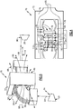
Figure 2 is a perspective view of an embodiment of a heat exchanger. -
Figure 3 is a sectional view of the example heat exchanger embodiment. -
Figure 4 is a cross section of the example heat exchanger embodiment. -
Figure 5 is a schematic view of the example heat exchanger embodiment. -
Figure 6 is a cross section of an embodiment of an inner manifold of the example heat exchanger. -
Figure 1 schematically illustrates an examplegas turbine engine 20 that includes afan section 22, acompressor section 24, acombustor section 26 and aturbine section 28. Alternative engines might include an augmenter section (not shown) among other systems or features. Thefan section 22 drives air along a bypass flow path B while thecompressor section 24 draws air in along a core flow path C where air is compressed and communicated to acombustor section 26. In thecombustor section 26, air is mixed with fuel and ignited to generate a high energy exhaust gas stream that expands through theturbine section 28 where energy is extracted and utilized to drive thefan section 22 and thecompressor section 24. - Although the disclosed non-limiting embodiment depicts a two-spool turbofan gas turbine engine, it should be understood that the concepts described herein are not limited to use with two-spool turbofans as the teachings may be applied to other types of turbine engines; for example a turbine engine including a three-spool architecture in which three spools concentrically rotate about a common axis and where a low spool enables a low pressure turbine to drive a fan via a gearbox, an intermediate spool that enables an intermediate pressure turbine to drive a first compressor of the compressor section, and a high spool that enables a high pressure turbine to drive a high pressure compressor of the compressor section.
- The
example engine 20 generally includes alow speed spool 30 and a high speed spool 32 mounted for rotation about an engine central longitudinal axis A relative to an enginestatic structure 36 viaseveral bearing systems 38. It should be understood that various bearingsystems 38 at various locations may alternatively or additionally be provided. - The
low speed spool 30 generally includes aninner shaft 40 that connects afan 42 and a low pressure (or first)compressor section 44 to a low pressure (or first)turbine section 46. Theinner shaft 40 drives thefan 42 through a speed change device, such as a gearedarchitecture 48, to drive thefan 42 at a lower speed than thelow speed spool 30. The high-speed spool 32 includes anouter shaft 50 that interconnects a high pressure (or second)compressor section 52 and a high pressure (or second)turbine section 54. Theinner shaft 40 and theouter shaft 50 are concentric and rotate via the bearingsystems 38 about the engine central longitudinal axis A. - A combustor 56 is arranged between the
high pressure compressor 52 and thehigh pressure turbine 54. In one example, thehigh pressure turbine 54 includes at least two stages to provide a double stagehigh pressure turbine 54. In another example, thehigh pressure turbine 54 includes only a single stage. As used herein, a "high pressure" compressor or turbine experiences a higher pressure than a corresponding "low pressure" compressor or turbine. - The example
low pressure turbine 46 has a pressure ratio that is greater than about 5. The pressure ratio of the examplelow pressure turbine 46 is measured prior to an inlet of thelow pressure turbine 46 as related to the pressure measured at the outlet of thelow pressure turbine 46 prior to an exhaust nozzle. - A
mid-turbine frame 58 of the enginestatic structure 36 is arranged generally between thehigh pressure turbine 54 and thelow pressure turbine 46. Themid-turbine frame 58 furthersupports bearing systems 38 in theturbine section 28 as well as setting airflow entering thelow pressure turbine 46. - Airflow through the core airflow path C is compressed by the
low pressure compressor 44 then by thehigh pressure compressor 52 mixed with fuel and ignited in the combustor 56 to produce high energy exhaust gases that are then expanded through thehigh pressure turbine 54 andlow pressure turbine 46. Themid-turbine frame 58 includesvanes 60, which are in the core airflow path and function as an inlet guide vane for thelow pressure turbine 46. Utilizing thevane 60 of themid-turbine frame 58 as the inlet guide vane forlow pressure turbine 46 decreases the length of thelow pressure turbine 46 without increasing the axial length of themid-turbine frame 58. Reducing or eliminating the number of vanes in thelow pressure turbine 46 shortens the axial length of theturbine section 28. Thus, the compactness of thegas turbine engine 20 is increased and a higher power density may be achieved. - The disclosed
gas turbine engine 20 in one example is a high-bypass geared aircraft engine. In a further example, thegas turbine engine 20 includes a bypass ratio greater than about six, with an example embodiment being greater than about ten. The example gearedarchitecture 48 is an epicyclical gear train, such as a planetary gear system, star gear system or other known gear system, with a gear reduction ratio of greater than about 2.3. - In one disclosed embodiment, the
gas turbine engine 20 includes a bypass ratio greater than about ten and the fan diameter is significantly larger than an outer diameter of thelow pressure compressor 44. It should be understood, however, that the above parameters are only exemplary of one embodiment of a gas turbine engine including a geared architecture and that the present disclosure is applicable to other gas turbine engines. - A significant amount of thrust is provided by the bypass flow B due to the high bypass ratio. The
fan section 22 of theengine 20 is designed for a particular flight condition -- typically cruise at about 0.8 Mach and about 35,000 feet (10,668 m). The flight condition of 0.8 Mach and 35,000 ft. (10,668 m), with the engine at its best fuel consumption - also known as "bucket cruise Thrust Specific Fuel Consumption ('TSFC')" - is the industry standard parameter of pound-mass (lbm) of fuel per hour being burned divided by pound-force (lbf) of thrust the engine produces at that minimum point. - "Low fan pressure ratio" is the pressure ratio across the fan blade alone, without a Fan Exit Guide Vane ("FEGV") system. The low fan pressure ratio as disclosed herein according to one non-limiting embodiment is less than about 1.50. In another non-limiting embodiment the low fan pressure ratio is less than about 1.45.
- "Low corrected fan tip speed" is the actual fan tip speed in ft/sec divided by an industry standard temperature correction of [(Tram °R)/(518.7°R)]0.5 (where °R = K x 9/5). The "Low corrected fan tip speed", as disclosed herein according to one non-limiting embodiment, is less than about 1150 ft/second (350.5 m/s).
- The example gas turbine engine includes the
fan 42 that comprises in one non-limiting embodiment less than about twenty-six fan blades. In another non-limiting embodiment, thefan section 22 includes less than about twenty fan blades. Moreover, in one disclosed embodiment thelow pressure turbine 46 includes no more than about six turbine rotor schematically indicated at 34. In another non-limiting example embodiment thelow pressure turbine 46 includes about three turbine rotors. A ratio between the number offan blades 42 and the number of low pressure turbine rotors is between about 3.3 and about 8.6. The examplelow pressure turbine 46 provides the driving power to rotate thefan section 22 and therefore the relationship between the number of turbine rotors 34 in thelow pressure turbine 46 and the number ofblades 42 in thefan section 22 disclose an examplegas turbine engine 20 with increased power transfer efficiency. - Increased gas turbine engine efficiencies are realized by increasing operating pressures and temperatures. However, challenges are raised in that the parts and components associated with a high pressure turbine require additional cooling air as the overall pressure ratio increases. Temperatures of the high energy gases through the turbine section can be much greater than the melting temperatures of the materials utilized in the fabrication of turbine components.
- The
example engine 20 includes a cooled cooling air system (CCA) 62 that receives air from anoutlet 94 within thecompressor section 24. Air from theoutlet 94 is at a first temperature T1 and a first pressure P1.Bypass air 66 at a second temperature T2 and second pressure P2 is fed through aheat exchange 70 to coolairflow 64 from thecompressor section 24. The second temperature T2 and second pressure P2 is significantly lower than the first temperature T1 and first pressure P1. Theairflow 64 is cooled in theheat exchanger 70 and directed as cooled coolingair 68 tolocations 96 within theturbine section 28. The cooled coolingair 68 that is supplied to theturbine section 28 is at a third temperature T3 that is cooler than the first temperature T1 and at a third pressure P3 that is substantially the same as the second pressure P2. - The temperature of the
airflow 64 from thecompressor section 24 may be as high as about 1500° F (815° C). Theairflow 66 from the bypass flow path B is at ambient temperatures that can be well below 0° F (-17° C). Accordingly, the difference between temperatures generates significant thermal gradients within theheat exchanger 70. - Referring to
Figures 2 and3 with continued reference toFigure 1 , theexample heat exchanger 70 includes anouter manifold 72 that supports aninner manifold 78. Theouter manifold 72 includes aninlet 80 that receivesairflow 66 that is at the second temperature T2 and second pressure P2. Theinner manifold 78 receivesairflow 64 from thecompressor section 24 that is at the first temperature T1 and first pressure P1. In this example, the first pressure P1 and first temperature T1 is much higher than the second temperature T2 and second pressure P2. Accordingly, the temperature gradient between theairflow 66 and theairflow 64 is significant and therefore generates a corresponding difference in temperature between theinner manifold 78 and theouter manifold 72 that is significant. - The
outer manifold 72 includes anouter cavity 74. Theouter cavity 74 surrounds aninner shell 76. Theinner shell 76 defines aninner cavity 84 and includes plurality ofimpingement openings 94. Theinner shell 76 also includesfingers 82 that support theinner manifold 78 within theouter manifold 72. Airflow entering theinlet 80 is communicated from theouter cavity 74 through theimpingement openings 94 directly onto surfaces of theinner manifold 78. - The
inner manifold 78 includespassages 86 forairflow 64 from thecompressor section 24. Thepassages 86 are separated byinsulator pockets 88 that do not include airflow. The insulator pockets 88 reduce differences in temperature across theinner manifold 78 to reduce thermal strains that may be caused by the elevated operational temperatures. - Referring to
Figures 4 and 5 with continued reference toFigure 3 , coolingair 64 tapped from thecompressor section 24 is communicated through thepassages 86 of theinner manifold 78.Colder airflow 66 is communicated through theinlet 80 of theouter manifold 72 and into theouter cavity 74. Theouter cavity 74 surrounds theinner shell 76. Theinner shell 76 includes the plurality ofimpingement openings 94 that direct airflow againstouter surfaces 75 of theinner manifold 78 in a direction indicated byarrows 110. The impingement airflow transfers thermal energy and cools the coolingairflow 64 through theinner manifold 78. - The
inner shell 76 is open on first andsecond sides post-infringement airflow 98 exits through the first andsecond sides passages 86 within theinner manifold 78. Thepost impingement airflow 98 is communicated to a lower pressure sink for air such as the fan bypass flow or the ambient environment. - The
inner manifold 78 is supported within theinner shell 76 by thefingers 82. Thefingers 82 includes a compliant configuration to accommodate the differences in thermal growth between theinner manifold 78 and theinner shells 76. In this example, thefingers 82 include abent portion 112 that is disposed midway between theinner manifold 78 and theinner shell 76. Thebent configuration 112 changes a thermal growth load between theinner manifold 78 and theinner shell 76 into a bending moment that reduces thermal strains on both theinner manifold 78 and theinner shell 76. - The
inner manifold 78 is unconstrained along amajor axis 114 by theinner shell 76. Accordingly, thermal growth along themajor axis 114 is not constrained by theinner shell 76. In the disclosed example embodiment, theinner manifold 78 is supported by theinner shell 76, but not attached to theinner shell 76 to enable accommodations of differences in thermal growth. Accordingly, theinner manifold 78 is unconstrained for thermal growth along themajor axis 114 and thefingers 82 accommodate thermal growth of theinner manifold 78 in direction transverse to themajor axis 114. - Referring to
Figure 6 with continued reference toFigures 4 and 5 , the exampleinner manifold 78 includes theflow passages 86 for theairflow 64 from thecompressor section 24. The passages include alength 100 that is transverse to themajor axis 114 and aligned with the direction of impingement flow indicated by thearrows 110. Thepassages 86 include afirst end 104 and asecond end 106 that define peaks along theouter surface 75 betweenvalleys 116. Impingement flow is directed along theouter surface 75 at theends valleys 116 between thepassages 86. - Each of the
passages 86 includes thelength 100, awidth 108 at each end and awidth 102 at amidpoint 118. Thewidth 108 at theends width 102 at themidpoint 118 between thefirst end 104 and thesecond end 106. In the disclosed embodiment, each of thepassages 86 includes thewidth 102 that is greater than awidth 108 at theends - The
inner manifold 78 further includes insulator pockets 88. The insulator pockets 88 are disposed between thepassages 86 but are not in communication with airflow from thecompressor section 24 or other sources of airflow. In the disclosed embodiment, there are twoinsulator pockets 88 disposed between each of thepassages 86. The insulator pockets 88 generate relatively cool areas within the otherwise hotinner manifold 78. The cool areas provided by the insulator pockets 88 counteract lengthwise thermal growth aligned with the direction of themajor axis 114. The insulator pockets 88 therefore provide a reduction in thermal growth that reduces stresses imparted on theinner manifold 78 and surrounding structures such as theinner shell 76. - Accordingly, the
example heat exchanger 70 provides for the efficient cooling of cooling air at elevated thermal gradients while maintaining desired flow rates that enable increased engine operating efficiencies. - Although an example embodiment has been disclosed, a worker of ordinary skill in this art would recognize that certain modifications would come within the scope of this disclosure. For that reason, the following claims should be studied to determine the scope and content of this disclosure.
Claims (12)
- A heat exchanger assembly (70) comprising:an outer manifold (72) defining an outer cavity (74);an inner cavity (84) defined by an inner shell (76) supported within the outer manifold (72) and at least partially surrounded by the outer cavity (74), the inner shell (76) including a plurality of impingement openings (94) for directing airflow into the inner cavity (84); andan inner manifold (78) supported within the inner cavity (84), wherein the inner manifold (78) is exposed to impingement airflow through the plurality of impingement openings (94) in the inner shell (76), and the inner manifold (78) includes a plurality of flow passages (86) and at least one insulator pocket (88) substantially aligned with the plurality of flow passages (86).
- The heat exchanger assembly (70) as recited in claim 1, wherein the inner shell (76) includes at least two fingers (82) supporting the inner manifold (78), and the at least two fingers (82) are compliant to accommodate thermal expansion of the inner manifold (78).
- The heat exchanger assembly (70) as recited in claim 2, including at least one opening for airflow in each of the at least two fingers (82).
- The heat exchanger assembly (70) as recited in claim 1, 2 or 3, wherein the inner cavity (84) is open at opposing first and second ends (90, 92) transverse to a direction of impingement flow (98).
- The heat exchanger assembly (70) as recited in claim 4, wherein the outer manifold (72) defines an inlet (80) into the outer cavity (74).
- The heat exchanger assembly (70) as recited in any preceding claim, including at least two insulator pockets (88) disposed between each of the plurality of flow passages (86).
- The heat exchanger assembly (70) as recited in any preceding claim, wherein the at least one insulator pocket (88) is closed to airflow.
- The heat exchanger assembly (70) as recited in any preceding claim, wherein each of the plurality of passages (86) includes a length (100) substantially aligned with cooling airflow from the plurality of impingement openings (94), and the length (100) of each of the plurality of passages (86) is greater than a width transverse to the direction of the cooling airflow from the plurality of impingement openings (94).
- The heat exchanger assembly (70) as recited in claim 8, wherein each of the plurality of passages (86) includes a midpoint between a first end (104) and a second end (106), and a width (102) at the midpoint (112) is greater than a width (108) at each of the first end (104) and the second end (106).
- The heat exchanger assembly (70) as recited in claim 9, wherein an outer surface (75) of the inner manifold (78) includes peaks corresponding to the first end (104) and the second end (106) separated by valleys (116).
- A cooled cooling air system (62) for a gas turbine engine (20) comprising:a first source of airflow (64) at a first pressure (P1) and temperature (T1);a second source of airflow (66) at a second pressure (P2) and temperature (T2), the second temperature (T2) and pressure (P2) less than the first temperature (T1) and pressure (P1); andthe heat exchanger assembly (70) of any preceding claim, further comprising a cold inlet in communication with airflow (66) from the second source, and a hot inlet in communication with airflow (64) from the first source, wherein the plurality of impingement openings (94) direct airflow from the outer manifold (72) into the inner cavity (84).
- A gas turbine engine assembly comprising:a compressor section (24) including a bleed air opening for a first source of airflow (64) at a first pressure (P1) and first temperature (T1);a second source of airflow (66) at a second pressure (P2) and a second temperature (T2);the heat exchanger assembly (70) of any of claims 1 to 10, further comprising a cold inlet in communication with airflow (66) from the second source, and a hot inlet in communication with airflow (64) from the first source, wherein the plurality of impingement openings (94) direct airflow from the outer manifold (72) into the inner cavity (84); anda turbine section (28) including at least one cooling air passage receiving cooled airflow (68) from an outlet of the inner manifold (78).
Applications Claiming Priority (1)
| Application Number | Priority Date | Filing Date | Title |
|---|---|---|---|
| US15/148,051 US10260422B2 (en) | 2016-05-06 | 2016-05-06 | Heat temperature gradient heat exchanger |
Publications (2)
| Publication Number | Publication Date |
|---|---|
| EP3242105A1 true EP3242105A1 (en) | 2017-11-08 |
| EP3242105B1 EP3242105B1 (en) | 2018-12-19 |
Family
ID=58692415
Family Applications (1)
| Application Number | Title | Priority Date | Filing Date |
|---|---|---|---|
| EP17169955.6A Active EP3242105B1 (en) | 2016-05-06 | 2017-05-08 | Heat temperature gradient heat exchanger |
Country Status (2)
| Country | Link |
|---|---|
| US (1) | US10260422B2 (en) |
| EP (1) | EP3242105B1 (en) |
Cited By (1)
| Publication number | Priority date | Publication date | Assignee | Title |
|---|---|---|---|---|
| US11204204B2 (en) * | 2019-03-08 | 2021-12-21 | Toyota Motor Engineering & Manufacturing North America, Inc. | Acoustic absorber with integrated heat sink |
Families Citing this family (5)
| Publication number | Priority date | Publication date | Assignee | Title |
|---|---|---|---|---|
| US10436115B2 (en) * | 2016-08-22 | 2019-10-08 | United Technologies Corporation | Heat exchanger for gas turbine engine with support damper mounting |
| US20180356106A1 (en) * | 2017-06-09 | 2018-12-13 | Trane International Inc. | Heat Exchanger Elevated Temperature Protection Sleeve |
| EP3550106B1 (en) | 2018-04-06 | 2024-10-09 | RTX Corporation | Cooling air for gas turbine engine with thermally isolated cooling air delivery |
| RU2680636C1 (en) * | 2018-05-14 | 2019-02-25 | Федеральное государственное унитарное предприятие "Центральный институт авиационного моторостроения имени П.И. Баранова" | Cooling system of a multi-circuit gas turbine unit |
| CN115095445A (en) * | 2022-05-26 | 2022-09-23 | 中国科学院工程热物理研究所 | Tail jet pipe with sandwich structure |
Citations (5)
| Publication number | Priority date | Publication date | Assignee | Title |
|---|---|---|---|---|
| US5918458A (en) * | 1997-02-14 | 1999-07-06 | General Electric Company | System and method of providing clean filtered cooling air to a hot portion of a gas turbine engine |
| WO2002097354A1 (en) * | 2001-05-25 | 2002-12-05 | Anglia Polytechnic University | A heat exchanger |
| WO2004013557A1 (en) * | 2002-08-01 | 2004-02-12 | Hiflux Limited | Heat exchanger and use thereof |
| US20140352315A1 (en) * | 2013-05-31 | 2014-12-04 | General Electric Company | Cooled cooling air system for a gas turbine |
| EP2811249A1 (en) * | 2013-06-06 | 2014-12-10 | Honeywell International Inc. | Unitary heat exchangers having integrally-formed compliant heat exchanger tubes and heat exchange systems including the same |
Family Cites Families (13)
| Publication number | Priority date | Publication date | Assignee | Title |
|---|---|---|---|---|
| US3705621A (en) | 1971-06-25 | 1972-12-12 | Lummus Co | Air-cooled heat exchanger |
| US4512397A (en) | 1982-05-27 | 1985-04-23 | Walter Stark | Housing for cross flow heat exchanger |
| CA2107464C (en) | 1991-04-15 | 2003-12-09 | Terry R. Galloway | Very high temperature heat exchanger |
| US5267608A (en) | 1992-07-27 | 1993-12-07 | General Electric Company | Heat exchanger and reactor for aircraft and propulsion systems |
| US5458187A (en) | 1993-12-01 | 1995-10-17 | Honeywell Inc. | Dual core air-to-air heat exchanger |
| DE10001112A1 (en) | 2000-01-13 | 2001-07-19 | Alstom Power Schweiz Ag Baden | Cooling air cooler for gas turbine unit, with water separator on cooling air side behind jet device in flow direction |
| US6536231B2 (en) | 2001-05-31 | 2003-03-25 | Carrier Corporation | Tube and shell heat exchanger for multiple circuit refrigerant system |
| US6904747B2 (en) * | 2002-08-30 | 2005-06-14 | General Electric Company | Heat exchanger for power generation equipment |
| US8376036B2 (en) | 2007-11-02 | 2013-02-19 | Az Evap, Llc | Air to air heat exchanger |
| US8266889B2 (en) | 2008-08-25 | 2012-09-18 | General Electric Company | Gas turbine engine fan bleed heat exchanger system |
| US8826901B2 (en) | 2010-01-20 | 2014-09-09 | Carrier Corporation | Primary heat exchanger design for condensing gas furnace |
| US9074829B2 (en) | 2011-12-01 | 2015-07-07 | The Boeing Company | Lightweight high temperature heat exchanger |
| EP3092388B8 (en) | 2014-01-07 | 2021-03-03 | Raytheon Technologies Corporation | Cross-stream heat exchanger |
-
2016
- 2016-05-06 US US15/148,051 patent/US10260422B2/en active Active
-
2017
- 2017-05-08 EP EP17169955.6A patent/EP3242105B1/en active Active
Patent Citations (5)
| Publication number | Priority date | Publication date | Assignee | Title |
|---|---|---|---|---|
| US5918458A (en) * | 1997-02-14 | 1999-07-06 | General Electric Company | System and method of providing clean filtered cooling air to a hot portion of a gas turbine engine |
| WO2002097354A1 (en) * | 2001-05-25 | 2002-12-05 | Anglia Polytechnic University | A heat exchanger |
| WO2004013557A1 (en) * | 2002-08-01 | 2004-02-12 | Hiflux Limited | Heat exchanger and use thereof |
| US20140352315A1 (en) * | 2013-05-31 | 2014-12-04 | General Electric Company | Cooled cooling air system for a gas turbine |
| EP2811249A1 (en) * | 2013-06-06 | 2014-12-10 | Honeywell International Inc. | Unitary heat exchangers having integrally-formed compliant heat exchanger tubes and heat exchange systems including the same |
Cited By (1)
| Publication number | Priority date | Publication date | Assignee | Title |
|---|---|---|---|---|
| US11204204B2 (en) * | 2019-03-08 | 2021-12-21 | Toyota Motor Engineering & Manufacturing North America, Inc. | Acoustic absorber with integrated heat sink |
Also Published As
| Publication number | Publication date |
|---|---|
| US20170321605A1 (en) | 2017-11-09 |
| US10260422B2 (en) | 2019-04-16 |
| EP3242105B1 (en) | 2018-12-19 |
Similar Documents
| Publication | Publication Date | Title |
|---|---|---|
| EP3242105B1 (en) | Heat temperature gradient heat exchanger | |
| EP3106646B2 (en) | Turbofan engine with a cooled cooling air system and a corresponding method | |
| EP2951419B1 (en) | Gas turbine engine with lower bifurcation heat exchanger | |
| US11339723B2 (en) | Geared turbofan high gearbox power density | |
| EP3889535B1 (en) | Duct mounted heat exchanger | |
| EP3052762B1 (en) | Feature to provide cooling flow to a turbine rotor disk | |
| EP3039264B1 (en) | Gas turbine engine diffuser cooling and mixing arrangement | |
| US9188009B2 (en) | Bore cavity thermal conditioning system | |
| EP2935833B1 (en) | Gas turbine engine including a pre-diffuser heat exchanger | |
| EP2807357B1 (en) | Heat exchanger | |
| EP3330524B1 (en) | Heat exchanger mounted at rear of gas turbine engine for challenging temperature applications | |
| US10526916B2 (en) | Heat exchanger with heat resistant center body | |
| US20150292358A1 (en) | Gas turbine engine inner case including non-symmetrical bleed slots | |
| US20160032730A1 (en) | Obtuse angle chevron trip strip | |
| EP3054094B1 (en) | Gas turbine engine turbine vane baffle and serpentine cooling passage | |
| EP3219959B1 (en) | Intercooled cooling air using existing heat exchanger | |
| EP3617454B1 (en) | Variable heat transfer collector baffle | |
| EP3961016B1 (en) | Gas turbine engine geared architecture | |
| EP3569841B1 (en) | Intercooled cooling air with heat exchanger packaging | |
| US20190242270A1 (en) | Heat transfer augmentation feature for components of gas turbine engines | |
| EP3508693B1 (en) | Segregated cooling air passages for turbine vane | |
| US11815022B2 (en) | Platform serpentine re-supply | |
| US20160069210A1 (en) | Windback heat shield |
Legal Events
| Date | Code | Title | Description |
|---|---|---|---|
| PUAI | Public reference made under article 153(3) epc to a published international application that has entered the european phase |
Free format text: ORIGINAL CODE: 0009012 |
|
| STAA | Information on the status of an ep patent application or granted ep patent |
Free format text: STATUS: THE APPLICATION HAS BEEN PUBLISHED |
|
| AK | Designated contracting states |
Kind code of ref document: A1 Designated state(s): AL AT BE BG CH CY CZ DE DK EE ES FI FR GB GR HR HU IE IS IT LI LT LU LV MC MK MT NL NO PL PT RO RS SE SI SK SM TR |
|
| AX | Request for extension of the european patent |
Extension state: BA ME |
|
| STAA | Information on the status of an ep patent application or granted ep patent |
Free format text: STATUS: REQUEST FOR EXAMINATION WAS MADE |
|
| 17P | Request for examination filed |
Effective date: 20180508 |
|
| RBV | Designated contracting states (corrected) |
Designated state(s): AL AT BE BG CH CY CZ DE DK EE ES FI FR GB GR HR HU IE IS IT LI LT LU LV MC MK MT NL NO PL PT RO RS SE SI SK SM TR |
|
| GRAP | Despatch of communication of intention to grant a patent |
Free format text: ORIGINAL CODE: EPIDOSNIGR1 |
|
| STAA | Information on the status of an ep patent application or granted ep patent |
Free format text: STATUS: GRANT OF PATENT IS INTENDED |
|
| RIC1 | Information provided on ipc code assigned before grant |
Ipc: F28F 9/02 20060101AFI20180611BHEP Ipc: F02K 3/115 20060101ALI20180611BHEP |
|
| INTG | Intention to grant announced |
Effective date: 20180627 |
|
| GRAS | Grant fee paid |
Free format text: ORIGINAL CODE: EPIDOSNIGR3 |
|
| GRAA | (expected) grant |
Free format text: ORIGINAL CODE: 0009210 |
|
| STAA | Information on the status of an ep patent application or granted ep patent |
Free format text: STATUS: THE PATENT HAS BEEN GRANTED |
|
| AK | Designated contracting states |
Kind code of ref document: B1 Designated state(s): AL AT BE BG CH CY CZ DE DK EE ES FI FR GB GR HR HU IE IS IT LI LT LU LV MC MK MT NL NO PL PT RO RS SE SI SK SM TR |
|
| REG | Reference to a national code |
Ref country code: GB Ref legal event code: FG4D |
|
| REG | Reference to a national code |
Ref country code: CH Ref legal event code: EP |
|
| REG | Reference to a national code |
Ref country code: IE Ref legal event code: FG4D |
|
| REG | Reference to a national code |
Ref country code: DE Ref legal event code: R096 Ref document number: 602017001447 Country of ref document: DE |
|
| REG | Reference to a national code |
Ref country code: AT Ref legal event code: REF Ref document number: 1079188 Country of ref document: AT Kind code of ref document: T Effective date: 20190115 |
|
| REG | Reference to a national code |
Ref country code: NL Ref legal event code: MP Effective date: 20181219 |
|
| PG25 | Lapsed in a contracting state [announced via postgrant information from national office to epo] |
Ref country code: FI Free format text: LAPSE BECAUSE OF FAILURE TO SUBMIT A TRANSLATION OF THE DESCRIPTION OR TO PAY THE FEE WITHIN THE PRESCRIBED TIME-LIMIT Effective date: 20181219 Ref country code: LV Free format text: LAPSE BECAUSE OF FAILURE TO SUBMIT A TRANSLATION OF THE DESCRIPTION OR TO PAY THE FEE WITHIN THE PRESCRIBED TIME-LIMIT Effective date: 20181219 Ref country code: HR Free format text: LAPSE BECAUSE OF FAILURE TO SUBMIT A TRANSLATION OF THE DESCRIPTION OR TO PAY THE FEE WITHIN THE PRESCRIBED TIME-LIMIT Effective date: 20181219 Ref country code: LT Free format text: LAPSE BECAUSE OF FAILURE TO SUBMIT A TRANSLATION OF THE DESCRIPTION OR TO PAY THE FEE WITHIN THE PRESCRIBED TIME-LIMIT Effective date: 20181219 Ref country code: BG Free format text: LAPSE BECAUSE OF FAILURE TO SUBMIT A TRANSLATION OF THE DESCRIPTION OR TO PAY THE FEE WITHIN THE PRESCRIBED TIME-LIMIT Effective date: 20190319 Ref country code: NO Free format text: LAPSE BECAUSE OF FAILURE TO SUBMIT A TRANSLATION OF THE DESCRIPTION OR TO PAY THE FEE WITHIN THE PRESCRIBED TIME-LIMIT Effective date: 20190319 |
|
| REG | Reference to a national code |
Ref country code: LT Ref legal event code: MG4D |
|
| REG | Reference to a national code |
Ref country code: AT Ref legal event code: MK05 Ref document number: 1079188 Country of ref document: AT Kind code of ref document: T Effective date: 20181219 |
|
| PG25 | Lapsed in a contracting state [announced via postgrant information from national office to epo] |
Ref country code: RS Free format text: LAPSE BECAUSE OF FAILURE TO SUBMIT A TRANSLATION OF THE DESCRIPTION OR TO PAY THE FEE WITHIN THE PRESCRIBED TIME-LIMIT Effective date: 20181219 Ref country code: GR Free format text: LAPSE BECAUSE OF FAILURE TO SUBMIT A TRANSLATION OF THE DESCRIPTION OR TO PAY THE FEE WITHIN THE PRESCRIBED TIME-LIMIT Effective date: 20190320 Ref country code: AL Free format text: LAPSE BECAUSE OF FAILURE TO SUBMIT A TRANSLATION OF THE DESCRIPTION OR TO PAY THE FEE WITHIN THE PRESCRIBED TIME-LIMIT Effective date: 20181219 Ref country code: SE Free format text: LAPSE BECAUSE OF FAILURE TO SUBMIT A TRANSLATION OF THE DESCRIPTION OR TO PAY THE FEE WITHIN THE PRESCRIBED TIME-LIMIT Effective date: 20181219 |
|
| PG25 | Lapsed in a contracting state [announced via postgrant information from national office to epo] |
Ref country code: NL Free format text: LAPSE BECAUSE OF FAILURE TO SUBMIT A TRANSLATION OF THE DESCRIPTION OR TO PAY THE FEE WITHIN THE PRESCRIBED TIME-LIMIT Effective date: 20181219 |
|
| PG25 | Lapsed in a contracting state [announced via postgrant information from national office to epo] |
Ref country code: IT Free format text: LAPSE BECAUSE OF FAILURE TO SUBMIT A TRANSLATION OF THE DESCRIPTION OR TO PAY THE FEE WITHIN THE PRESCRIBED TIME-LIMIT Effective date: 20181219 Ref country code: ES Free format text: LAPSE BECAUSE OF FAILURE TO SUBMIT A TRANSLATION OF THE DESCRIPTION OR TO PAY THE FEE WITHIN THE PRESCRIBED TIME-LIMIT Effective date: 20181219 Ref country code: CZ Free format text: LAPSE BECAUSE OF FAILURE TO SUBMIT A TRANSLATION OF THE DESCRIPTION OR TO PAY THE FEE WITHIN THE PRESCRIBED TIME-LIMIT Effective date: 20181219 Ref country code: PT Free format text: LAPSE BECAUSE OF FAILURE TO SUBMIT A TRANSLATION OF THE DESCRIPTION OR TO PAY THE FEE WITHIN THE PRESCRIBED TIME-LIMIT Effective date: 20190419 Ref country code: PL Free format text: LAPSE BECAUSE OF FAILURE TO SUBMIT A TRANSLATION OF THE DESCRIPTION OR TO PAY THE FEE WITHIN THE PRESCRIBED TIME-LIMIT Effective date: 20181219 |
|
| PG25 | Lapsed in a contracting state [announced via postgrant information from national office to epo] |
Ref country code: EE Free format text: LAPSE BECAUSE OF FAILURE TO SUBMIT A TRANSLATION OF THE DESCRIPTION OR TO PAY THE FEE WITHIN THE PRESCRIBED TIME-LIMIT Effective date: 20181219 Ref country code: SM Free format text: LAPSE BECAUSE OF FAILURE TO SUBMIT A TRANSLATION OF THE DESCRIPTION OR TO PAY THE FEE WITHIN THE PRESCRIBED TIME-LIMIT Effective date: 20181219 Ref country code: SK Free format text: LAPSE BECAUSE OF FAILURE TO SUBMIT A TRANSLATION OF THE DESCRIPTION OR TO PAY THE FEE WITHIN THE PRESCRIBED TIME-LIMIT Effective date: 20181219 Ref country code: RO Free format text: LAPSE BECAUSE OF FAILURE TO SUBMIT A TRANSLATION OF THE DESCRIPTION OR TO PAY THE FEE WITHIN THE PRESCRIBED TIME-LIMIT Effective date: 20181219 Ref country code: IS Free format text: LAPSE BECAUSE OF FAILURE TO SUBMIT A TRANSLATION OF THE DESCRIPTION OR TO PAY THE FEE WITHIN THE PRESCRIBED TIME-LIMIT Effective date: 20190419 |
|
| REG | Reference to a national code |
Ref country code: DE Ref legal event code: R097 Ref document number: 602017001447 Country of ref document: DE |
|
| PLBE | No opposition filed within time limit |
Free format text: ORIGINAL CODE: 0009261 |
|
| STAA | Information on the status of an ep patent application or granted ep patent |
Free format text: STATUS: NO OPPOSITION FILED WITHIN TIME LIMIT |
|
| PG25 | Lapsed in a contracting state [announced via postgrant information from national office to epo] |
Ref country code: AT Free format text: LAPSE BECAUSE OF FAILURE TO SUBMIT A TRANSLATION OF THE DESCRIPTION OR TO PAY THE FEE WITHIN THE PRESCRIBED TIME-LIMIT Effective date: 20181219 Ref country code: DK Free format text: LAPSE BECAUSE OF FAILURE TO SUBMIT A TRANSLATION OF THE DESCRIPTION OR TO PAY THE FEE WITHIN THE PRESCRIBED TIME-LIMIT Effective date: 20181219 |
|
| 26N | No opposition filed |
Effective date: 20190920 |
|
| PG25 | Lapsed in a contracting state [announced via postgrant information from national office to epo] |
Ref country code: MC Free format text: LAPSE BECAUSE OF FAILURE TO SUBMIT A TRANSLATION OF THE DESCRIPTION OR TO PAY THE FEE WITHIN THE PRESCRIBED TIME-LIMIT Effective date: 20181219 |
|
| REG | Reference to a national code |
Ref country code: BE Ref legal event code: MM Effective date: 20190531 |
|
| PG25 | Lapsed in a contracting state [announced via postgrant information from national office to epo] |
Ref country code: LU Free format text: LAPSE BECAUSE OF NON-PAYMENT OF DUE FEES Effective date: 20190508 Ref country code: SI Free format text: LAPSE BECAUSE OF FAILURE TO SUBMIT A TRANSLATION OF THE DESCRIPTION OR TO PAY THE FEE WITHIN THE PRESCRIBED TIME-LIMIT Effective date: 20181219 |
|
| PG25 | Lapsed in a contracting state [announced via postgrant information from national office to epo] |
Ref country code: TR Free format text: LAPSE BECAUSE OF FAILURE TO SUBMIT A TRANSLATION OF THE DESCRIPTION OR TO PAY THE FEE WITHIN THE PRESCRIBED TIME-LIMIT Effective date: 20181219 |
|
| PG25 | Lapsed in a contracting state [announced via postgrant information from national office to epo] |
Ref country code: IE Free format text: LAPSE BECAUSE OF NON-PAYMENT OF DUE FEES Effective date: 20190508 |
|
| PG25 | Lapsed in a contracting state [announced via postgrant information from national office to epo] |
Ref country code: BE Free format text: LAPSE BECAUSE OF NON-PAYMENT OF DUE FEES Effective date: 20190531 |
|
| PG25 | Lapsed in a contracting state [announced via postgrant information from national office to epo] |
Ref country code: CH Free format text: LAPSE BECAUSE OF NON-PAYMENT OF DUE FEES Effective date: 20200531 Ref country code: LI Free format text: LAPSE BECAUSE OF NON-PAYMENT OF DUE FEES Effective date: 20200531 |
|
| PG25 | Lapsed in a contracting state [announced via postgrant information from national office to epo] |
Ref country code: CY Free format text: LAPSE BECAUSE OF FAILURE TO SUBMIT A TRANSLATION OF THE DESCRIPTION OR TO PAY THE FEE WITHIN THE PRESCRIBED TIME-LIMIT Effective date: 20181219 |
|
| PG25 | Lapsed in a contracting state [announced via postgrant information from national office to epo] |
Ref country code: MT Free format text: LAPSE BECAUSE OF FAILURE TO SUBMIT A TRANSLATION OF THE DESCRIPTION OR TO PAY THE FEE WITHIN THE PRESCRIBED TIME-LIMIT Effective date: 20181219 Ref country code: HU Free format text: LAPSE BECAUSE OF FAILURE TO SUBMIT A TRANSLATION OF THE DESCRIPTION OR TO PAY THE FEE WITHIN THE PRESCRIBED TIME-LIMIT; INVALID AB INITIO Effective date: 20170508 |
|
| PG25 | Lapsed in a contracting state [announced via postgrant information from national office to epo] |
Ref country code: MK Free format text: LAPSE BECAUSE OF FAILURE TO SUBMIT A TRANSLATION OF THE DESCRIPTION OR TO PAY THE FEE WITHIN THE PRESCRIBED TIME-LIMIT Effective date: 20181219 |
|
| REG | Reference to a national code |
Ref country code: DE Ref legal event code: R081 Ref document number: 602017001447 Country of ref document: DE Owner name: RAYTHEON TECHNOLOGIES CORPORATION (N.D.GES.D.S, US Free format text: FORMER OWNER: UNITED TECHNOLOGIES CORPORATION, FARMINGTON, CONN., US Ref country code: DE Ref legal event code: R081 Ref document number: 602017001447 Country of ref document: DE Owner name: RTX CORPORATION (N.D.GES.D. STAATES DELAWARE),, US Free format text: FORMER OWNER: UNITED TECHNOLOGIES CORPORATION, FARMINGTON, CONN., US |
|
| P01 | Opt-out of the competence of the unified patent court (upc) registered |
Effective date: 20230520 |
|
| PGFP | Annual fee paid to national office [announced via postgrant information from national office to epo] |
Ref country code: DE Payment date: 20250423 Year of fee payment: 9 |
|
| PGFP | Annual fee paid to national office [announced via postgrant information from national office to epo] |
Ref country code: GB Payment date: 20250423 Year of fee payment: 9 |
|
| PGFP | Annual fee paid to national office [announced via postgrant information from national office to epo] |
Ref country code: FR Payment date: 20250423 Year of fee payment: 9 |
|
| REG | Reference to a national code |
Ref country code: DE Ref legal event code: R081 Ref document number: 602017001447 Country of ref document: DE Owner name: RTX CORPORATION (N.D.GES.D. STAATES DELAWARE),, US Free format text: FORMER OWNER: RAYTHEON TECHNOLOGIES CORPORATION (N.D.GES.D.STAATES DELAWARE), ARLINGTON, VA, US |