EP3242044A1 - Fastening system and method - Google Patents
Fastening system and method Download PDFInfo
- Publication number
- EP3242044A1 EP3242044A1 EP17169407.8A EP17169407A EP3242044A1 EP 3242044 A1 EP3242044 A1 EP 3242044A1 EP 17169407 A EP17169407 A EP 17169407A EP 3242044 A1 EP3242044 A1 EP 3242044A1
- Authority
- EP
- European Patent Office
- Prior art keywords
- fastener
- nut
- securing device
- channel
- distal end
- Prior art date
- Legal status (The legal status is an assumption and is not a legal conclusion. Google has not performed a legal analysis and makes no representation as to the accuracy of the status listed.)
- Granted
Links
Images


Classifications
-
- F—MECHANICAL ENGINEERING; LIGHTING; HEATING; WEAPONS; BLASTING
- F16—ENGINEERING ELEMENTS AND UNITS; GENERAL MEASURES FOR PRODUCING AND MAINTAINING EFFECTIVE FUNCTIONING OF MACHINES OR INSTALLATIONS; THERMAL INSULATION IN GENERAL
- F16B—DEVICES FOR FASTENING OR SECURING CONSTRUCTIONAL ELEMENTS OR MACHINE PARTS TOGETHER, e.g. NAILS, BOLTS, CIRCLIPS, CLAMPS, CLIPS OR WEDGES; JOINTS OR JOINTING
- F16B39/00—Locking of screws, bolts or nuts
- F16B39/22—Locking of screws, bolts or nuts in which the locking takes place during screwing down or tightening
- F16B39/225—Locking of screws, bolts or nuts in which the locking takes place during screwing down or tightening by means of a settable material
-
- B—PERFORMING OPERATIONS; TRANSPORTING
- B25—HAND TOOLS; PORTABLE POWER-DRIVEN TOOLS; MANIPULATORS
- B25B—TOOLS OR BENCH DEVICES NOT OTHERWISE PROVIDED FOR, FOR FASTENING, CONNECTING, DISENGAGING, OR HOLDING
- B25B13/00—Spanners; Wrenches
- B25B13/48—Spanners; Wrenches for special purposes
- B25B13/481—Spanners; Wrenches for special purposes for operating in areas having limited access
-
- F—MECHANICAL ENGINEERING; LIGHTING; HEATING; WEAPONS; BLASTING
- F16—ENGINEERING ELEMENTS AND UNITS; GENERAL MEASURES FOR PRODUCING AND MAINTAINING EFFECTIVE FUNCTIONING OF MACHINES OR INSTALLATIONS; THERMAL INSULATION IN GENERAL
- F16B—DEVICES FOR FASTENING OR SECURING CONSTRUCTIONAL ELEMENTS OR MACHINE PARTS TOGETHER, e.g. NAILS, BOLTS, CIRCLIPS, CLAMPS, CLIPS OR WEDGES; JOINTS OR JOINTING
- F16B23/00—Specially shaped nuts or heads of bolts or screws for rotations by a tool
- F16B23/0007—Specially shaped nuts or heads of bolts or screws for rotations by a tool characterised by the shape of the recess or the protrusion engaging the tool
-
- F—MECHANICAL ENGINEERING; LIGHTING; HEATING; WEAPONS; BLASTING
- F16—ENGINEERING ELEMENTS AND UNITS; GENERAL MEASURES FOR PRODUCING AND MAINTAINING EFFECTIVE FUNCTIONING OF MACHINES OR INSTALLATIONS; THERMAL INSULATION IN GENERAL
- F16B—DEVICES FOR FASTENING OR SECURING CONSTRUCTIONAL ELEMENTS OR MACHINE PARTS TOGETHER, e.g. NAILS, BOLTS, CIRCLIPS, CLAMPS, CLIPS OR WEDGES; JOINTS OR JOINTING
- F16B23/00—Specially shaped nuts or heads of bolts or screws for rotations by a tool
- F16B23/0007—Specially shaped nuts or heads of bolts or screws for rotations by a tool characterised by the shape of the recess or the protrusion engaging the tool
- F16B23/0038—Specially shaped nuts or heads of bolts or screws for rotations by a tool characterised by the shape of the recess or the protrusion engaging the tool substantially prismatic with up to six edges, e.g. triangular, square, pentagonal, Allen-type cross-sections
-
- F—MECHANICAL ENGINEERING; LIGHTING; HEATING; WEAPONS; BLASTING
- F16—ENGINEERING ELEMENTS AND UNITS; GENERAL MEASURES FOR PRODUCING AND MAINTAINING EFFECTIVE FUNCTIONING OF MACHINES OR INSTALLATIONS; THERMAL INSULATION IN GENERAL
- F16B—DEVICES FOR FASTENING OR SECURING CONSTRUCTIONAL ELEMENTS OR MACHINE PARTS TOGETHER, e.g. NAILS, BOLTS, CIRCLIPS, CLAMPS, CLIPS OR WEDGES; JOINTS OR JOINTING
- F16B5/00—Joining sheets or plates, e.g. panels, to one another or to strips or bars parallel to them
- F16B5/02—Joining sheets or plates, e.g. panels, to one another or to strips or bars parallel to them by means of fastening members using screw-thread
-
- F—MECHANICAL ENGINEERING; LIGHTING; HEATING; WEAPONS; BLASTING
- F16—ENGINEERING ELEMENTS AND UNITS; GENERAL MEASURES FOR PRODUCING AND MAINTAINING EFFECTIVE FUNCTIONING OF MACHINES OR INSTALLATIONS; THERMAL INSULATION IN GENERAL
- F16B—DEVICES FOR FASTENING OR SECURING CONSTRUCTIONAL ELEMENTS OR MACHINE PARTS TOGETHER, e.g. NAILS, BOLTS, CIRCLIPS, CLAMPS, CLIPS OR WEDGES; JOINTS OR JOINTING
- F16B35/00—Screw-bolts; Stay-bolts; Screw-threaded studs; Screws; Set screws
- F16B35/04—Screw-bolts; Stay-bolts; Screw-threaded studs; Screws; Set screws with specially-shaped head or shaft in order to fix the bolt on or in an object
- F16B35/041—Specially-shaped shafts
Definitions
- Examples of the present disclosure generally relate to fastening systems and methods, and, more particularly, to fastening systems and methods that are configured to secure a fastener to a nut within confined spaces.
- a fastener may be positioned within aligned through-holes of two components (such as panels).
- a nut threadably engages a distal end of the fastener.
- the head of the fastener is engaged by a first tool while the nut is engaged with a second tool.
- the nut is held in position by the second tool, while the fastener is torqued in relation to the nut with the first tool, which secures the fastener to the nut, and thereby securely connects the two components together.
- the fastener is engaged by the first tool on one side of the components, while the nut is engaged by the second tool on an opposite side of the components.
- space may be limited on one or both sides of the components.
- an area around the nut that is used to secure components together may be restricted. An individual may find it difficult to grasp or otherwise engage the nut due to the restricted space around the nut.
- Certain fastening methods use nut plates or cages that are configured to engage fasteners.
- the spaces around components that are to be secured together may not be readily accessible to an individual.
- the space on one or both side of the components may be too small to accommodate a nut plate and/or a cage.
- the fastening system includes a fastener including a shaft having a distal end extending from a head.
- a first channel is formed through the fastener between the head and the distal end.
- a nut is configured to be connected to the fastener.
- the nut includes a second channel that is coaxially aligned with the first channel.
- At least a portion of the distal end may include external threads and the nut includes internal threads.
- the internal threads of the nut threadably engage the external threads of the fastener.
- One of the fastener or the nut is configured to be internally engaged through the first channel or the second channel to threadably secure the nut to the fastener.
- the fastening system may also include a first securing device having a portion that extends into the first and second channels.
- One of the first or second channels has a size and shape that conforms to an outer surface of the portion of the first securing device.
- the outer surface has a hexagonal cross-section.
- the fastening system may also include a second securing device having an operative head that extends into the first channel.
- the operative head rotationally constrains the fastener.
- the operative head includes a passage formed therethrough. The portion of the first securing device extends through the passage.
- the second channel may have a size and shape that conforms to an outer surface of a portion of a first securing device.
- the first securing device may be configured to rotationally constrain the nut.
- the first channel may include a device-passage channel that is configured to allow a portion of a first securing device to radially move therein.
- the second channel may include a device-conforming channel that is configured to conform to a size and shape of an outer surface of the portion of the first securing device.
- the nut is secured to a surface of the component(s) prior to contact with the fastener.
- the nut may be secured to the surface of the component(s) through at least one of an adhesive, bonding, and a filament.
- the fastening method includes positioning a distal end of a fastener with respect to a first side of the component(s), aligning the distal end of the fastener with an opening of the component(s), urging the distal end of the fastener into and through the opening of the component(s) from the first side, connecting a nut to the distal end of the fastener at a second side of the component(s) that is opposite from the first side, and urging a portion of a first securing device from the first side of the component(s) into a first channel formed through the fastener and a second channel formed through the nut.
- the urging includes rotationally constraining one of the fastener or the nut by the portion of the first securing device.
- the method may also include rotationally restraining the other of the fastener or the nut that is not rotationally constrained by the first securing device, and rotating the first securing device to rotate the one of the fastener or the nut that is rotationally constrained by the first securing device.
- the rotationally restraining comprises using a second securing device having an operative head that extends into the first channel.
- Examples of the present disclosure provide fastening systems and methods that may be configured to secure and remove fasteners with respect to nuts from one side or end, instead of both the fastener and the nut being grasped or engaged by separate tools.
- a securing device is used to internally engage one of the fastener or the nut in order to secure the nut to the fastener.
- Examples of the present disclosure provide a fastening system and method that include a fastener and a nut.
- the fastener is a hollow fastener having a central channel formed therethrough.
- a securing device (such as a hex wrench) is configured to pass through the central channel and internally engage the nut.
- the securing device passes through the central channel from a first end and engages the nut on the opposite second end.
- the securing device may be operated from the first side or end to secure the nut to the fastener.
- the fastener may be a screw, bolt, or the like.
- the fastener may include a raised head that is configured to extend over a component.
- the fastener may include a tapered or other such head that is configured to flush mount with respect an outer surface of a component.
- Certain examples of the present disclosure provide a fastening system that includes a hollow fastener and a nut.
- a securing device is positioned through the hollow fastener and engages reciprocal features of the nut. The securing device is then rotated to rotate the nut with respect to the fastener, such that the nut threadably secures to the fastener. The securing device is operated to rotate the nut with respect to the fastener from the inside of the nut.
- Certain examples of the present disclosure provide a fastening method that includes extending a securing device through a hollow fastener.
- the extending includes inserting the securing device through a head end of the fastener toward and through a distal threaded end of the fastener.
- the method also includes engaging a mating feature of a nut positioned on or otherwise proximate to the distal threaded end of the fastener with the securing device.
- the method also includes rotating the securing device to rotate the nut, thereby threadably securing the nut to the fastener.
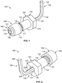
- Figure 1 illustrates a perspective view of a fastening system 100 from a first end 102, according to an example of the present disclosure.
- the fastening system 100 includes a fastener 104, a nut 106, and a securing device 108.
- the fastener 104 includes a head 110 connected to a shaft 112.
- the head 110 may include an outer periphery 114.
- the outer periphery 114 may be shaped as a hexagon.
- the outer periphery 114 is configured to be grasped by an individual, engaged by a tool (such as a hex wrench), and/or the like.
- the outer periphery 114 may be shaped and sized other than shown.
- the outer periphery 114 may be shaped as a square, octagon, triangle, circle, and/or the like.
- the shaft 112 includes a distal end 116 that includes external threads 117.
- the threads 117 are configured to threadably engage reciprocal internal threads formed within the nut 106.
- the threads 117 may extend a longer or shorter distance over the outer surface of the shaft 112 than shown.
- the nut 106 includes an annular outer wall 118 connected to an end cap 120.
- the outer wall 118 may be cylindrical, conical, and/or the like. Interior surfaces of the outer wall 118 include internal threads that are configured to threadably engage the threads 117 of the distal end 116 of the shaft 112.
- Internal walls 121 of the nut 106 define a device-conforming channel 122 that is formed through at least a portion of the end cap 120.
- the device-conforming channel 122 may extend entirely through the end cap 120.
- the end cap 120 may be closed ended such that the device-conforming channel 122 does not extend entirely through the end cap 120.
- the device-conforming channel 122 is sized and shaped to reciprocally engage a distal end 124 of the securing device 108.
- the device-conforming channel 122 may be hexagonal and configured to reciprocally engage a hexagonal outer surface of the distal end 124 of the securing device 108.
- the device-conforming channel 122 may be sized and shaped differently than shown.
- the device-conforming channel 122 may be sized and shaped as a square, if the distal end 124 of the securing device 108 has a square-shaped outer perimeter.
- the device-conforming channel 122 may be triangular in shape, if the distal end 124 of the securing device 108 has a triangular-shaped outer perimeter.
- the device-conforming channel 122 may be sized and shaped to be complementary to the size and shape of the outer perimeter of the distal end 124 of the securing device 108.
- the complementary interface between the device conforming channel 122 and the corresponding outer surface of the distal end 124 of the securing device 108 radially or otherwise rotationally links the nut 106 to the securing device 108 when the distal end 124 is positioned within the device-conforming channel 122.
- rotational movement of the nut 106 is controlled and dictated by the securing device 108.
- the securing device 108 may include a proximal end 126 that connects to the distal end 124.
- the proximal end 126 may connect to a bend 128 that couples to the proximal end 126 to the distal end 124 through an intermediate extension 129.
- the proximal end 126 may provide a handle that is configured to be grasped by an individual.
- the securing device 108 may include a hexagonal outer periphery.
- an axial cross-section of the securing device 108 may be hexagonal.
- less than all of the securing device 108 may include a hexagonal axial cross-section.
- the distal end 124 of the securing device may have a hexagonal axial cross-section, but the proximal end 126 and/or the bend 128 may include a different axial cross-section.
- the securing device 108 may not include the bend 128. Instead, the securing device 108 may be formed as a linear device having a linear longitudinal axis. In at least one example, the securing device 108 may be configured to be secured to a tool, such as a drill. In at least one example, the securing device 108 may be a drill bit. Further, as noted above, the distal end 124 may have a different axial cross-section than shown.
- the shape of the outer periphery of the distal end 124 is complementary or otherwise corresponds to the shape of the device-conforming channel 122 of the nut 106.
- the device-conforming channel 122 receives and rotationally constrains the distal end 124 of the securing device in a radial direction, so that rotation of the securing device 108 causes a corresponding rotation of the nut 106.
- the distal end 124 of the securing device 108 extends into and/or through the device-conforming channel 122 of the nut 106, the nut 106 is constrained in a radial direction by the securing device 108.
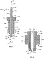
- Figure 2 illustrates a perspective view of the fastening system 100 from a second end 132, according to an example of the present disclosure.
- the second end 132 is opposite from the first end 102.
- the nut 106 is at the first end 102, while the head 110 of the fastener 104 is proximate to the second end 132.
- first and second are merely used to indicate a number of features.
- the first end 102 may be a second end
- the second end 132 may be a first end.
- the fastener 104 may be hollow, and include internal walls 133 that define a central, internal device-passage channel 134 that is formed through the fastener 104.
- the device-passage channel 134 extends from and through the head 110 to and through the distal end 116.
- the device-passage channel 134 includes an axial cross-section that differs from that of the device-conforming channel 122 of the nut 106.
- the device-passage channel 134 may include a circular cross-section.
- a clearance space 135 may be formed between the internal walls 133 that define the device-passage channel 134 and an outer surface of the securing device 108.
- the internal walls 133 may touch the securing device 108, but may not conform thereto.
- the device-passage channel 134 does not securely engage the securing device 108.
- the smooth, circular internal diameter of the fastener 104 that defines the device-passage channel 134 allows the securing device 108 to extend therethrough, but does not radially or otherwise rotationally constrain the securing device 108. Accordingly, rotation of the securing device 108 may not cause a corresponding rotation of the fastener 104.
- the fastener 104 and the nut 106 may be coaxial. Accordingly, the center of the device-conforming channel 122 may be coaxially aligned with a longitudinal axis of the fastener 104. Further, the distal end 124 and the extension 129 of the securing device 108 may also be coaxial with the fastener 104 and the nut 106.
- Figure 3 illustrates an axial cross-sectional view of the fastening system 100, according to an example of the present disclosure.
- a central longitudinal axis 136 is common to the distal end 124 and the extension 129 of the securing device 108, as well as the fastener 104 and the nut 106.
- the device-passage channel 134 formed through the fastener 104 may not engage an outer surface of the securing device 108.
- the device-passage channel 134 is not complementary to the outer surface of the securing device 108. As such, when the securing device 108 is rotated, the fastener 104 generally does not rotate in a corresponding manner.
- the device-conforming channel 122 formed through the nut 106 is sized and shaped to be complementary to the outer surface of the distal end 124 of the securing device 108.
- the distal end 124 is positioned through the device-conforming channel 122 such that the complementary interface between the distal end 124 and the nut 106 radially locks the nut 106 to the securing device 108. Accordingly, rotation of the securing device 108 about the longitudinal axis 136 causes a corresponding rotation of the nut 106.
- the nut 106 may first be coupled to the distal end 116 of the fastener 104. As shown, the nut 106 may be threaded onto the distal end 116 such that internal threads 138 of the nut 106 threadably engage the outer threads 117 of the distal end 116 of the fastener 104.
- the distal end 124 of the securing device 108 is urged into the device-passage channel 134 of the fastener 104 through the head 110 in the direction of arrow A.
- the securing device 108 continues to be urged in the direction of arrow A, until the distal end 124 passes out of the device-passage channel 134 and into the aligned complementary device-conforming channel 122 of the nut 106.
- the fastener 104 may be rotationally restrained (for example, held in a fixed radial position) such as by an individual grasping the head 110 with fingers or a tool. As the fastener 104 is rotationally restrained, the securing device 108 is then rotated in a securing direction (as shown by arc B) about the longitudinal axis 136.
- the nut 106 rotates in response thereto, while the fastener 104 remains stationary (as the device-conforming channel 122 of the nut 106 is complementary to the securing device 108, but the securing device 108 freely rotates within the internal device-passage channel 134 formed through fastener 104).
- the nut 106 is secured (for example, tightened) to the distal end 116 of the fastener 104.
- the fastener 104 is released, and the securing device 108 is removed from the fastener 104 and the nut 106 in a direction that is opposite from arrow A.
- the securing device 108 may be positioned through the fastener 104 and the nut 106 as shown. The fastener 104 may then be rotationally restrained, and the securing device 108 may be rotated about the longitudinal axis 136 in a direction that is opposite from arc B.
- the internal device-passage channel 134 of the fastener 104 may be sized and shaped to be rotationally constrained by the securing device 108, while the nut 106 is not rotationally constrained by the securing device.
- the internal channel 134 may have a complementary size and shape that corresponds to the outer surface of the securing device 108, while the device-conforming channel 122 of the nut 106 may be cylindrical.
- the nut 106 may be fixed to a structure, such as a panel, and the securing device 108 may be rotated, thereby causing a corresponding rotation in the fastener 104, which secures the fastener 104 to the nut 106.
- Figure 4 illustrates an axial cross-sectional view of first and second components 140 and 142 secured together through the fastener 104 and the nut 106, according to an example of the present disclosure.
- the securing device 108 is used to secure the nut 106 to the fastener 104, as described above.
- An individual may secure the nut 106 to the fastener 104 by engaging the head 110 of the fastener 104 from a first side 144 of an assembly 146 that includes the components 140 and 142, and insert the securing device 108 through the fastener 104 and the nut 106 from the first side 144.
- the individual may then rotate the securing device 108 from the first side 144 to secure and/or disconnect the nut 106 from the fastener 104. In this manner, the individual need not engage an outer portion of the nut 106 from a second side 148 of the assembly 146. Instead, the securing device 108 passes through the internal device-passage channel 134 of the fastener 104 and the device-conforming channel 122 of the nut 106, and internally engages the nut 106 to secure and/or disconnect the nut 106 from the fastener 104.
- the aligned device-passage channel 134 and the device-conforming channel 122 provides an open passage 150.
- the open passage 150 may be left open.
- the open passage 150 may provide a drain through the assembly 146, for example.
- the open passage 150 may be plugged, such as with a sealant, a set screw, and/or the like.
- Figure 5 illustrates an axial cross-sectional view of the fastening system 100 coupled to the assembly 146, according to an example of the present disclosure.
- Figure 6 illustrates a perspective, partial internal view of the fastening system 100 coupled to the assembly 146.
- the head 110 of the fastener 104 is configured to be flush with an outer surface 160 of the component 140.
- a securing device 180 is used to rotationally constrain the fastener 104.
- the securing device 180 comprises an operative head 182 having a passage 184 formed therethrough.
- An outer surface of the operative head 182 is complementary to a head channel portion 186 formed through the device-passage channel 134.
- the outer surface of the operative head 182 may have a hexagonal shape, while the head channel portion 186 may be defined by internal walls that have an axial cross-section that is also hexagonal and configured to conform around the operative head 182.
- the operative head 182 may be connected to a handle 190.
- the fastener 104 is positioned through axially aligned openings 200 and 202 formed through the components 140 and 142.
- the nut 106 may then be connected to the distal end 116 of the fastener 104, as described above.
- the operative head 182 of the securing device 180 is then positioned within the head channel portion 186.
- the distal end 124 of the securing device 108 is then passed through the non-conforming passage 184 of the securing device 180, the device-passage channel 134 of the fastener 104, and the device-conforming channel 122 formed through the nut 106.
- the securing device 180 is then used to hold the fastener 104 in a radially-constrained position (for example, a locked position) while the securing device 108 is used to secure the nut 106 to the fastener 104, as described above.
- the securing device 108 may be held in position to hold the nut 106 in a radially-constrained position, while the securing device 180 is used to rotate the fastener 104 in relation to the nut 106, in order to secure the nut 106 to the fastener 104.
- Figure 7 illustrates a perspective, partial internal view of the assembly 146 secured together by the fastener 104 and the nut 106, according to an example of the present disclosure.
- the head channel portion 186 is defined by internal walls 210 that are configured to conform to an outer surface of operative head 182 (shown in Figures 5 and 6 ).
- the internal walls 210 may form a hexagonal head channel portion 186 that conforms to an outer hexagonal shape of the operative head 182.
- Figure 8 illustrates a lateral view of the assembly 146 secured together by fasteners 104 and nuts 106, according to an example of the present disclosure.
- the second side 148 of the assembly 146 may include restricted spaces 220 and 222.
- An individual may be unable to engage outer surfaces of the nuts 106 from the second side 148. Further, an individual may be unable to engage the nuts 106 with a tool from the second side 148.
- the fastening systems 100 shown and described above allow the nuts 106 to be securely connected to the fasteners 104 from the first side 144.
- the securing devices 108 and/or 180 described above allow an individual to securely connect the nuts 106 to the fasteners 104 without engaging outer portions of the nuts 106.
- Figure 9 illustrates a lateral view of the fastener 104 aligned with a nut 106 and openings 200 and 202 through components 140 and 142, respectively, according to an example of the present disclosure.
- the nut 106 may be initially secured to the component 142.
- the device-conforming channel 122 of the nut 106 may be axially aligned with the opening 202 of the component 142, and a lower edge 123 of the outer wall 118 of the nut 106 may be secured to a surface of the component 142 surrounding the opening 202, such as through adhesives, bonding, and/or the like.
- a filament 300 (such as a string, wire, or the like) may be used to hold the nut 106 in position until the fastener 104 initially mates with the nut 106. After the fastener 104 connects to the nut 106 (such as through a threaded engagement therebetween), the filament 300 may be removed in the direction of arrow C through the device-conforming channel 122 and the device-passage channel 134 (shown in Figures 3 and 4 , for example).
- the nut 106 may be held in place through adhesives, bonding, the filament 300, and/or the like, and the securing device 108 (shown in Figures 1-6 ) may be configured to radially constrain the fastener 104, so that the fastener 104 may be rotated by the securing device 108 to secure to the nut 106, which may be fixed in place on the component 142.
- Figure 10 illustrates a flow chart of a method of securing a nut to a fastener, according to an example of the present disclosure.
- the method begins at 400, in which a distal end of a fastener is positioned with respect to a first side of at least one component.
- the distal end may be positioned over opening of the component(s) from the first side.
- the distal end of the fastener is aligned with the opening of the component.
- the distal end of the fastener is coaxially aligned with the opening.
- the distal end of the fastener is urged into and through the opening of the component(s) from the first side.
- a head of the fastener may seat on a surface of the component(s) that surrounds the opening. In at least one other example, the head may flush mount with the surface of the component(s) that surrounds the opening.
- a nut is connected to the distal end of the fastener at a second side of the component(s). For example, an individual may initially thread the nut onto the distal end of the fastener. In at least one other example, the nut may be secured to the component, such as through adhesives, bonding, a filament, and/or the like.
- a portion of a securing device (such as a hex wrench) is urged from the first of the component(s) through a first internal channel formed through the fastener and a coaxial second internal channel formed through the nut.
- a securing device such as a hex wrench
- Either the first channel or the second channel conforms to an outer surface of the portion of the securing device, such that either the fastener or nut is rotationally constrained by the securing device.
- the other of the fastener or the nut is not rotationally constrained by the securing device.
- one of the fastener or the nut is rotationally restrained.
- a head of the fastener may be held by an individual, or with another securing device.
- the other securing device may include an operative head having an outer surface that fits within and conforms to a shape of a portion of the first channel.
- the operative head includes a passage through which the portion of the first securing device passes.
- the fastener or the nut is rotated by the securing device from the first side.
- the securing device rotates the fastener or nut relative to the other. In this manner, the nut is securely tightened to the fastener.
- Examples of the present disclosure provide fastening systems and methods that allow a fastener to be secured to a nut from one end thereof (and from one side of a component or assembly).
- the fastening systems and methods do not require nut plates, extra holes, or rivets in order to secure the fastener to the nut.
- One of the nut or the fastener is configured to be internally engaged by a first securing device, which is used to internally rotate the nut relative to the fastener.
- Another securing device (for example, a second securing device) having a hollow operative head may be used to radially constrain the fastener.
- the first securing device is configured to pass through the hollow operative head and internally engage the nut, for example.
- examples of the present disclosure provide systems and methods of efficiently securing a fastener to a nut within confined spaces.
- Examples of the present disclosure provide systems and methods of efficiently securing one or more components using a fastener and nut in which a securing device is used to engage both the fastener and nut from one side.
- a structure, limitation, or element that is "configured to” perform a task or operation is particularly structurally formed, constructed, or adapted in a manner corresponding to the task or operation.
- an object that is merely capable of being modified to perform the task or operation is not “configured to” perform the task or operation as used herein.
Landscapes
- Engineering & Computer Science (AREA)
- General Engineering & Computer Science (AREA)
- Mechanical Engineering (AREA)
- Connection Of Plates (AREA)
- Dowels (AREA)
Abstract
Description
- Examples of the present disclosure generally relate to fastening systems and methods, and, more particularly, to fastening systems and methods that are configured to secure a fastener to a nut within confined spaces.
- Various components are secured together through fasteners and nuts. For example, a fastener may be positioned within aligned through-holes of two components (such as panels). A nut threadably engages a distal end of the fastener. In general, the head of the fastener is engaged by a first tool while the nut is engaged with a second tool. The nut is held in position by the second tool, while the fastener is torqued in relation to the nut with the first tool, which secures the fastener to the nut, and thereby securely connects the two components together.
- Notably, the fastener is engaged by the first tool on one side of the components, while the nut is engaged by the second tool on an opposite side of the components. During the manufacture of various structures, however, space may be limited on one or both sides of the components. As an example, an area around the nut that is used to secure components together may be restricted. An individual may find it difficult to grasp or otherwise engage the nut due to the restricted space around the nut.
- Certain fastening methods use nut plates or cages that are configured to engage fasteners. However, the spaces around components that are to be secured together may not be readily accessible to an individual. Moreover, the space on one or both side of the components may be too small to accommodate a nut plate and/or a cage.
- It is with respect to these and other considerations that the disclosure made herein is presented.
- A need exists for a system and method of efficiently securing a fastener to a nut within confined spaces. A need exists for a system and method of efficiently securing components together using a fastener and nut in which a tool is used to engage both the fastener and nut from one side of the components.
- With those needs in mind, certain examples of the present disclosure provide a fastening system that is configured to be securely fastened from one side of at least one component. The fastening system includes a fastener including a shaft having a distal end extending from a head. A first channel is formed through the fastener between the head and the distal end. A nut is configured to be connected to the fastener. The nut includes a second channel that is coaxially aligned with the first channel.
- At least a portion of the distal end may include external threads and the nut includes internal threads. The internal threads of the nut threadably engage the external threads of the fastener.
- One of the fastener or the nut is configured to be internally engaged through the first channel or the second channel to threadably secure the nut to the fastener.
- The fastening system may also include a first securing device having a portion that extends into the first and second channels. One of the first or second channels has a size and shape that conforms to an outer surface of the portion of the first securing device. In at least one example, the outer surface has a hexagonal cross-section.
- The fastening system may also include a second securing device having an operative head that extends into the first channel. The operative head rotationally constrains the fastener. In at least one example, the operative head includes a passage formed therethrough. The portion of the first securing device extends through the passage.
- The second channel may have a size and shape that conforms to an outer surface of a portion of a first securing device. In at least one example, the first securing device may be configured to rotationally constrain the nut.
- The first channel may include a device-passage channel that is configured to allow a portion of a first securing device to radially move therein. The second channel may include a device-conforming channel that is configured to conform to a size and shape of an outer surface of the portion of the first securing device.
- In at least one example, the nut is secured to a surface of the component(s) prior to contact with the fastener. For example, the nut may be secured to the surface of the component(s) through at least one of an adhesive, bonding, and a filament.
- Certain examples of the present disclosure provide a fastening method that is configured to be performed from one side of at least one component. The fastening method includes positioning a distal end of a fastener with respect to a first side of the component(s), aligning the distal end of the fastener with an opening of the component(s), urging the distal end of the fastener into and through the opening of the component(s) from the first side, connecting a nut to the distal end of the fastener at a second side of the component(s) that is opposite from the first side, and urging a portion of a first securing device from the first side of the component(s) into a first channel formed through the fastener and a second channel formed through the nut. The urging includes rotationally constraining one of the fastener or the nut by the portion of the first securing device.
- The method may also include rotationally restraining the other of the fastener or the nut that is not rotationally constrained by the first securing device, and rotating the first securing device to rotate the one of the fastener or the nut that is rotationally constrained by the first securing device. In at least one example, the rotationally restraining comprises using a second securing device having an operative head that extends into the first channel.
-
-
Figure 1 illustrates a perspective view of a fastening system from a first end, according to an example of the present disclosure. -
Figure 2 illustrates a perspective view of a fastening system from a second end, according to an example of the present disclosure. -
Figure 3 illustrates an axial cross-sectional view of a fastening system, according to an example of the present disclosure. -
Figure 4 illustrates an axial cross-sectional view of first and second components secured together through a fastener and a nut, according to an example of the present disclosure. -
Figure 5 illustrates an axial cross-sectional view of a fastening system coupled to an assembly, according to an example of the present disclosure. -
Figure 6 illustrates a perspective, partial internal view of a fastening system coupled to an assembly, according to an example of the present disclosure. -
Figure 7 illustrates a perspective, partial internal view of an assembly secured together by a fastener and a nut, according to an example of the present disclosure. -
Figure 8 illustrates a lateral view of an assembly secured together by fasteners and nuts, according to an example of the present disclosure. -
Figure 9 illustrates a lateral view of a fastener aligned with a nut and openings through components, according to an example of the present disclosure. - The foregoing summary, as well as the following detailed description of certain examples will be better understood when read in conjunction with the appended drawings. As used herein, an element or step recited in the singular and preceded by the word "a" or "an" should be understood as not necessarily excluding the plural of the elements or steps. Further, references to "one example" are not intended to be interpreted as excluding the existence of additional examples that also incorporate the recited features. Moreover, unless explicitly stated to the contrary, examples "comprising" or "having" an element or a plurality of elements having a particular condition may include additional elements not having that condition.
- Examples of the present disclosure provide fastening systems and methods that may be configured to secure and remove fasteners with respect to nuts from one side or end, instead of both the fastener and the nut being grasped or engaged by separate tools. A securing device is used to internally engage one of the fastener or the nut in order to secure the nut to the fastener.
- Examples of the present disclosure provide a fastening system and method that include a fastener and a nut. In at least one example, the fastener is a hollow fastener having a central channel formed therethrough. A securing device (such as a hex wrench) is configured to pass through the central channel and internally engage the nut. The securing device passes through the central channel from a first end and engages the nut on the opposite second end. The securing device may be operated from the first side or end to secure the nut to the fastener.
- The fastener may be a screw, bolt, or the like. The fastener may include a raised head that is configured to extend over a component. In at least one example, the fastener may include a tapered or other such head that is configured to flush mount with respect an outer surface of a component.
- Certain examples of the present disclosure provide a fastening system that includes a hollow fastener and a nut. A securing device is positioned through the hollow fastener and engages reciprocal features of the nut. The securing device is then rotated to rotate the nut with respect to the fastener, such that the nut threadably secures to the fastener. The securing device is operated to rotate the nut with respect to the fastener from the inside of the nut.
- Certain examples of the present disclosure provide a fastening method that includes extending a securing device through a hollow fastener. The extending includes inserting the securing device through a head end of the fastener toward and through a distal threaded end of the fastener. The method also includes engaging a mating feature of a nut positioned on or otherwise proximate to the distal threaded end of the fastener with the securing device. The method also includes rotating the securing device to rotate the nut, thereby threadably securing the nut to the fastener.
-
Figure 1 illustrates a perspective view of afastening system 100 from afirst end 102, according to an example of the present disclosure. Thefastening system 100 includes afastener 104, anut 106, and asecuring device 108. - The
fastener 104 includes ahead 110 connected to ashaft 112. Thehead 110 may include anouter periphery 114. As shown inFigure 1 , theouter periphery 114 may be shaped as a hexagon. Theouter periphery 114 is configured to be grasped by an individual, engaged by a tool (such as a hex wrench), and/or the like. Optionally, theouter periphery 114 may be shaped and sized other than shown. For example, theouter periphery 114 may be shaped as a square, octagon, triangle, circle, and/or the like. - The
shaft 112 includes adistal end 116 that includesexternal threads 117. Thethreads 117 are configured to threadably engage reciprocal internal threads formed within thenut 106. Thethreads 117 may extend a longer or shorter distance over the outer surface of theshaft 112 than shown. - The
nut 106 includes an annularouter wall 118 connected to anend cap 120. Theouter wall 118 may be cylindrical, conical, and/or the like. Interior surfaces of theouter wall 118 include internal threads that are configured to threadably engage thethreads 117 of thedistal end 116 of theshaft 112. -
Internal walls 121 of thenut 106 define a device-conformingchannel 122 that is formed through at least a portion of theend cap 120. The device-conformingchannel 122 may extend entirely through theend cap 120. Optionally, theend cap 120 may be closed ended such that the device-conformingchannel 122 does not extend entirely through theend cap 120. - The device-conforming
channel 122 is sized and shaped to reciprocally engage adistal end 124 of the securingdevice 108. For example, the device-conformingchannel 122 may be hexagonal and configured to reciprocally engage a hexagonal outer surface of thedistal end 124 of the securingdevice 108. Optionally, the device-conformingchannel 122 may be sized and shaped differently than shown. For example, the device-conformingchannel 122 may be sized and shaped as a square, if thedistal end 124 of the securingdevice 108 has a square-shaped outer perimeter. As another example, the device-conformingchannel 122 may be triangular in shape, if thedistal end 124 of the securingdevice 108 has a triangular-shaped outer perimeter. In general, the device-conformingchannel 122 may be sized and shaped to be complementary to the size and shape of the outer perimeter of thedistal end 124 of the securingdevice 108. - The complementary interface between the
device conforming channel 122 and the corresponding outer surface of thedistal end 124 of the securingdevice 108 radially or otherwise rotationally links thenut 106 to the securingdevice 108 when thedistal end 124 is positioned within the device-conformingchannel 122. Thus, when thedistal end 124 is retained within the device-conformingchannel 122, rotational movement of thenut 106 is controlled and dictated by the securingdevice 108. - The securing
device 108 may include aproximal end 126 that connects to thedistal end 124. Theproximal end 126 may connect to abend 128 that couples to theproximal end 126 to thedistal end 124 through anintermediate extension 129. Theproximal end 126 may provide a handle that is configured to be grasped by an individual. As shown, the securingdevice 108 may include a hexagonal outer periphery. For example, an axial cross-section of the securingdevice 108 may be hexagonal. Optionally, less than all of the securingdevice 108 may include a hexagonal axial cross-section. For example, thedistal end 124 of the securing device may have a hexagonal axial cross-section, but theproximal end 126 and/or thebend 128 may include a different axial cross-section. - Optionally, the securing
device 108 may not include thebend 128. Instead, the securingdevice 108 may be formed as a linear device having a linear longitudinal axis. In at least one example, the securingdevice 108 may be configured to be secured to a tool, such as a drill. In at least one example, the securingdevice 108 may be a drill bit. Further, as noted above, thedistal end 124 may have a different axial cross-section than shown. - The shape of the outer periphery of the
distal end 124 is complementary or otherwise corresponds to the shape of the device-conformingchannel 122 of thenut 106. As such, the device-conformingchannel 122 receives and rotationally constrains thedistal end 124 of the securing device in a radial direction, so that rotation of the securingdevice 108 causes a corresponding rotation of thenut 106. When thedistal end 124 of the securingdevice 108 extends into and/or through the device-conformingchannel 122 of thenut 106, thenut 106 is constrained in a radial direction by the securingdevice 108. -
Figure 2 illustrates a perspective view of thefastening system 100 from asecond end 132, according to an example of the present disclosure. Thesecond end 132 is opposite from thefirst end 102. As shown, thenut 106 is at thefirst end 102, while thehead 110 of thefastener 104 is proximate to thesecond end 132. It is to be understood that the terms first and second are merely used to indicate a number of features. For example, thefirst end 102 may be a second end, while thesecond end 132 may be a first end. - The
fastener 104 may be hollow, and includeinternal walls 133 that define a central, internal device-passage channel 134 that is formed through thefastener 104. The device-passage channel 134 extends from and through thehead 110 to and through thedistal end 116. The device-passage channel 134 includes an axial cross-section that differs from that of the device-conformingchannel 122 of thenut 106. For example, the device-passage channel 134 may include a circular cross-section. Aclearance space 135 may be formed between theinternal walls 133 that define the device-passage channel 134 and an outer surface of the securingdevice 108. In at least one other example, theinternal walls 133 may touch the securingdevice 108, but may not conform thereto. As such, the device-passage channel 134 does not securely engage the securingdevice 108. For example, the smooth, circular internal diameter of thefastener 104 that defines the device-passage channel 134 allows the securingdevice 108 to extend therethrough, but does not radially or otherwise rotationally constrain the securingdevice 108. Accordingly, rotation of the securingdevice 108 may not cause a corresponding rotation of thefastener 104. - Referring to
Figures 1 and 2 , thefastener 104 and thenut 106 may be coaxial. Accordingly, the center of the device-conformingchannel 122 may be coaxially aligned with a longitudinal axis of thefastener 104. Further, thedistal end 124 and theextension 129 of the securingdevice 108 may also be coaxial with thefastener 104 and thenut 106. -
Figure 3 illustrates an axial cross-sectional view of thefastening system 100, according to an example of the present disclosure. A centrallongitudinal axis 136 is common to thedistal end 124 and theextension 129 of the securingdevice 108, as well as thefastener 104 and thenut 106. - As shown in
Figure 3 , the device-passage channel 134 formed through thefastener 104 may not engage an outer surface of the securingdevice 108. The device-passage channel 134 is not complementary to the outer surface of the securingdevice 108. As such, when the securingdevice 108 is rotated, thefastener 104 generally does not rotate in a corresponding manner. - In contrast, the device-conforming
channel 122 formed through thenut 106 is sized and shaped to be complementary to the outer surface of thedistal end 124 of the securingdevice 108. Thedistal end 124 is positioned through the device-conformingchannel 122 such that the complementary interface between thedistal end 124 and thenut 106 radially locks thenut 106 to the securingdevice 108. Accordingly, rotation of the securingdevice 108 about thelongitudinal axis 136 causes a corresponding rotation of thenut 106. - In operation, the
nut 106 may first be coupled to thedistal end 116 of thefastener 104. As shown, thenut 106 may be threaded onto thedistal end 116 such thatinternal threads 138 of thenut 106 threadably engage theouter threads 117 of thedistal end 116 of thefastener 104. - After the
nut 106 is initially connected to thefastener 104, thedistal end 124 of the securingdevice 108 is urged into the device-passage channel 134 of thefastener 104 through thehead 110 in the direction of arrow A. The securingdevice 108 continues to be urged in the direction of arrow A, until thedistal end 124 passes out of the device-passage channel 134 and into the aligned complementary device-conformingchannel 122 of thenut 106. - In order to fully secure the
nut 106 to thefastener 104, thefastener 104 may be rotationally restrained (for example, held in a fixed radial position) such as by an individual grasping thehead 110 with fingers or a tool. As thefastener 104 is rotationally restrained, the securingdevice 108 is then rotated in a securing direction (as shown by arc B) about thelongitudinal axis 136. As the securingdevice 108 is rotated, thenut 106 rotates in response thereto, while thefastener 104 remains stationary (as the device-conformingchannel 122 of thenut 106 is complementary to the securingdevice 108, but the securingdevice 108 freely rotates within the internal device-passage channel 134 formed through fastener 104). As the securingdevice 108 rotates thenut 106 in relation to thefastener 104, thenut 106 is secured (for example, tightened) to thedistal end 116 of thefastener 104. After thenut 106 is secured to thefastener 104, thefastener 104 is released, and the securingdevice 108 is removed from thefastener 104 and thenut 106 in a direction that is opposite from arrow A. - In order to disengage the
nut 106 from thefastener 104, the securingdevice 108 may be positioned through thefastener 104 and thenut 106 as shown. Thefastener 104 may then be rotationally restrained, and the securingdevice 108 may be rotated about thelongitudinal axis 136 in a direction that is opposite from arc B. - Alternatively, the internal device-
passage channel 134 of thefastener 104 may be sized and shaped to be rotationally constrained by the securingdevice 108, while thenut 106 is not rotationally constrained by the securing device. For example, theinternal channel 134 may have a complementary size and shape that corresponds to the outer surface of the securingdevice 108, while the device-conformingchannel 122 of thenut 106 may be cylindrical. In this example, thenut 106 may be fixed to a structure, such as a panel, and the securingdevice 108 may be rotated, thereby causing a corresponding rotation in thefastener 104, which secures thefastener 104 to thenut 106. -
Figure 4 illustrates an axial cross-sectional view of first andsecond components fastener 104 and thenut 106, according to an example of the present disclosure. Referring toFigures 3 and 4 , the securingdevice 108 is used to secure thenut 106 to thefastener 104, as described above. An individual may secure thenut 106 to thefastener 104 by engaging thehead 110 of thefastener 104 from afirst side 144 of anassembly 146 that includes thecomponents device 108 through thefastener 104 and thenut 106 from thefirst side 144. The individual may then rotate the securingdevice 108 from thefirst side 144 to secure and/or disconnect thenut 106 from thefastener 104. In this manner, the individual need not engage an outer portion of thenut 106 from asecond side 148 of theassembly 146. Instead, the securingdevice 108 passes through the internal device-passage channel 134 of thefastener 104 and the device-conformingchannel 122 of thenut 106, and internally engages thenut 106 to secure and/or disconnect thenut 106 from thefastener 104. - After the
securing device 108 is removed from thefastener 104 and thenut 106, the aligned device-passage channel 134 and the device-conformingchannel 122 provides anopen passage 150. Theopen passage 150 may be left open. Theopen passage 150 may provide a drain through theassembly 146, for example. Optionally, theopen passage 150 may be plugged, such as with a sealant, a set screw, and/or the like. -
Figure 5 illustrates an axial cross-sectional view of thefastening system 100 coupled to theassembly 146, according to an example of the present disclosure.Figure 6 illustrates a perspective, partial internal view of thefastening system 100 coupled to theassembly 146. Referring toFigures 5 and 6 , in this example, thehead 110 of thefastener 104 is configured to be flush with anouter surface 160 of thecomponent 140. - A securing
device 180 is used to rotationally constrain thefastener 104. The securingdevice 180 comprises anoperative head 182 having apassage 184 formed therethrough. An outer surface of theoperative head 182 is complementary to ahead channel portion 186 formed through the device-passage channel 134. For example, the outer surface of theoperative head 182 may have a hexagonal shape, while thehead channel portion 186 may be defined by internal walls that have an axial cross-section that is also hexagonal and configured to conform around theoperative head 182. Thus, when theoperative head 182 is positioned within thehead channel portion 186, thefastener 104 is rotationally constrained by the securingdevice 180. Theoperative head 182 may be connected to ahandle 190. - In operation, the
fastener 104 is positioned through axially alignedopenings components nut 106 may then be connected to thedistal end 116 of thefastener 104, as described above. Theoperative head 182 of the securingdevice 180 is then positioned within thehead channel portion 186. Thedistal end 124 of the securingdevice 108 is then passed through thenon-conforming passage 184 of the securingdevice 180, the device-passage channel 134 of thefastener 104, and the device-conformingchannel 122 formed through thenut 106. - The securing
device 180 is then used to hold thefastener 104 in a radially-constrained position (for example, a locked position) while the securingdevice 108 is used to secure thenut 106 to thefastener 104, as described above. Optionally, the securingdevice 108 may be held in position to hold thenut 106 in a radially-constrained position, while the securingdevice 180 is used to rotate thefastener 104 in relation to thenut 106, in order to secure thenut 106 to thefastener 104. -
Figure 7 illustrates a perspective, partial internal view of theassembly 146 secured together by thefastener 104 and thenut 106, according to an example of the present disclosure. As shown, thehead channel portion 186 is defined byinternal walls 210 that are configured to conform to an outer surface of operative head 182 (shown inFigures 5 and 6 ). For example, theinternal walls 210 may form a hexagonalhead channel portion 186 that conforms to an outer hexagonal shape of theoperative head 182. -
Figure 8 illustrates a lateral view of theassembly 146 secured together byfasteners 104 andnuts 106, according to an example of the present disclosure. As shown, thesecond side 148 of theassembly 146 may include restrictedspaces nuts 106 from thesecond side 148. Further, an individual may be unable to engage thenuts 106 with a tool from thesecond side 148. Referring toFigures 1-8 , thefastening systems 100 shown and described above allow thenuts 106 to be securely connected to thefasteners 104 from thefirst side 144. For example, the securingdevices 108 and/or 180 described above allow an individual to securely connect thenuts 106 to thefasteners 104 without engaging outer portions of the nuts 106. -
Figure 9 illustrates a lateral view of thefastener 104 aligned with anut 106 andopenings components nut 106 may be initially secured to thecomponent 142. For example, the device-conformingchannel 122 of thenut 106 may be axially aligned with theopening 202 of thecomponent 142, and alower edge 123 of theouter wall 118 of thenut 106 may be secured to a surface of thecomponent 142 surrounding theopening 202, such as through adhesives, bonding, and/or the like. - In at least one example, a filament 300 (such as a string, wire, or the like) may be used to hold the
nut 106 in position until thefastener 104 initially mates with thenut 106. After thefastener 104 connects to the nut 106 (such as through a threaded engagement therebetween), thefilament 300 may be removed in the direction of arrow C through the device-conformingchannel 122 and the device-passage channel 134 (shown inFigures 3 and 4 , for example). In at least one other example, thenut 106 may be held in place through adhesives, bonding, thefilament 300, and/or the like, and the securing device 108 (shown inFigures 1-6 ) may be configured to radially constrain thefastener 104, so that thefastener 104 may be rotated by the securingdevice 108 to secure to thenut 106, which may be fixed in place on thecomponent 142. -
Figure 10 illustrates a flow chart of a method of securing a nut to a fastener, according to an example of the present disclosure. The method begins at 400, in which a distal end of a fastener is positioned with respect to a first side of at least one component. For example, the distal end may be positioned over opening of the component(s) from the first side. - At 402, the distal end of the fastener is aligned with the opening of the component. For example, the distal end of the fastener is coaxially aligned with the opening.
- At 404, the distal end of the fastener is urged into and through the opening of the component(s) from the first side. A head of the fastener may seat on a surface of the component(s) that surrounds the opening. In at least one other example, the head may flush mount with the surface of the component(s) that surrounds the opening.
- At 406, a nut is connected to the distal end of the fastener at a second side of the component(s). For example, an individual may initially thread the nut onto the distal end of the fastener. In at least one other example, the nut may be secured to the component, such as through adhesives, bonding, a filament, and/or the like.
- At 408, a portion of a securing device (such as a hex wrench) is urged from the first of the component(s) through a first internal channel formed through the fastener and a coaxial second internal channel formed through the nut. Either the first channel or the second channel conforms to an outer surface of the portion of the securing device, such that either the fastener or nut is rotationally constrained by the securing device. The other of the fastener or the nut is not rotationally constrained by the securing device.
- At 410, one of the fastener or the nut is rotationally restrained. For example, a head of the fastener may be held by an individual, or with another securing device. In at least one example, the other securing device may include an operative head having an outer surface that fits within and conforms to a shape of a portion of the first channel. The operative head includes a passage through which the portion of the first securing device passes.
- At 412, the fastener or the nut is rotated by the securing device from the first side. The securing device rotates the fastener or nut relative to the other. In this manner, the nut is securely tightened to the fastener.
- Examples of the present disclosure provide fastening systems and methods that allow a fastener to be secured to a nut from one end thereof (and from one side of a component or assembly). The fastening systems and methods do not require nut plates, extra holes, or rivets in order to secure the fastener to the nut. One of the nut or the fastener is configured to be internally engaged by a first securing device, which is used to internally rotate the nut relative to the fastener. Another securing device (for example, a second securing device) having a hollow operative head may be used to radially constrain the fastener. The first securing device is configured to pass through the hollow operative head and internally engage the nut, for example.
- Further, the disclosure comprises embodiments according to the following clauses:
- A1. A fastening system that is configured to be securely fastened from one side of at least one component, the fastening system comprising:
- a fastener including a shaft having a distal end extending from a head, wherein a first channel is formed through the fastener between the head and the distal end; and
- a nut that is configured to be connected to the fastener, wherein the nut includes a second channel that is coaxially aligned with the first channel.
- A2. The fastening system of clause A1, wherein at least a portion of the distal end includes external threads and the nut includes internal threads, and wherein the internal threads of the nut threadably engage the external threads of the fastener.
- A3. The fastening system of clause A1 or A2, wherein one of the fastener or the nut is configured to be internally engaged through the first channel or the second channel to threadably secure the nut to the fastener.
- A4. The fastening system of any of clauses A1 to A3, further comprising a first securing device having a portion that extends into the first and second channels, wherein one of the first or second channels has a size and shape that conforms to an outer surface of the portion of the first securing device.
- A5. The fastening system of clause A4, wherein the outer surface has a hexagonal cross-section.
- A6. The fastening system of clause A4 or A5, further comprising a second securing device having an operative head that extends into the first channel, wherein the operative head rotationally constrains the fastener.
- A7. The fastening system of clause A6, wherein the operative head comprises a passage formed therethrough, wherein the portion of the first securing device extends through the passage.
- A8. The fastening system of any of clauses A1 to A7, wherein the second channel has a size and shape that conforms to an outer surface of a portion of a first securing device, and wherein the first securing device is configured to rotationally constrain the nut.
- A9. The fastening system of any of clauses A1 to A8, wherein the first channel includes a device-passage channel that is configured to allow a portion of a first securing device to radially move therein, and wherein the second channel includes a device-conforming channel that is configured to conform to a size and shape of an outer surface of the portion of the first securing device.
- A10. The fastening system of any of clauses A1 to A9, wherein the nut is secured to a surface of the at least one component prior to contact with the fastener.
- A11. The fastening system of clause A10, wherein the nut is secured to the surface of the at least one component through at least one of an adhesive, bonding, and a filament.
- A12. A fastening method that is configured to be performed from one side of at least one component, the fastening method comprising:
- positioning a distal end of a fastener with respect to a first side of the at least one component;
- aligning the distal end of the fastener with an opening of the at least one component;
- urging the distal end of the fastener into and through the opening of the at least one component from the first side;
- connecting a nut to the distal end of the fastener at a second side of the at least one component that is opposite from the first side; and
- urging a portion of a first securing device from the first side of the at least one component into a first channel formed through the fastener and a second channel formed through the nut, wherein the urging comprises rotationally constraining one of the fastener or the nut by the portion of the first securing device.
- A13. The fastening method of clause A12, further comprising:
- rotationally restraining the other of the fastener or the nut that is not rotationally constrained by the first securing device; and
- rotating the first securing device to rotate the one of the fastener or the nut that is rotationally constrained by the first securing device.
- A14. The fastening method of clause A13, wherein the rotationally restraining comprises using a second securing device having an operative head that extends into the first channel.
- A15. The fastening method of clause A14, further comprising extending the portion of the first securing device through a passage formed through the operative head of the second securing device.
- A16. The fastening method of any of clauses A12 to A15, wherein the rotating the first securing device comprises threadably engaging internal threads of the nut with external threads of the fastener.
- A17. The fastening method of any of clauses A12 to A16, wherein the first channel includes a device-passage channel that is configured to allow the portion of the first securing device to radially move therein, and wherein the second channel includes a device-conforming channel that is configured to conform to a size and shape of an outer surface of the portion of first securing device.
- A18. The fastening method of any of clauses A12 to A17, further comprising securing the nut to the second side of the at least one component, and wherein the securing the nut to the second side of the at least one component comprises securing the nut to the second side through at least one of an adhesive, bonding, and a filament.
- A19. A fastening system that is configured to be securely fastened from one side of at least one component, the fastening system comprising:
- a fastener including a shaft having a distal end and external threads extending from a head, wherein a device-passage channel is formed through the fastener between the head and the distal end;
- a nut including internal threads and a device-conforming channel, wherein the device-passage channel is coaxially aligned with the device-conforming channel, and wherein the internal threads of the nut engage the external threads of the fastener; and
- a first securing device having a portion that extends into the device-passage channel and the device-conforming channel, wherein the device-passage channel allows the portion of the first securing device to radially move therein, wherein the device-conforming channel has a size and shape that conforms to an outer surface of the portion of the first securing device, and wherein the outer surface of the first securing device is configured to internally engage the nut through the device-conforming channel and rotate the nut relative to the fastener to threadably secure the nut to the fastener.
- A20. The fastening system of clause A19, further comprising a second securing device having an operative head that extends into the device-passage channel, wherein the operative head rotationally constrains the fastener, wherein the operative head comprises a passage formed therethrough, and wherein the portion of the first securing device extends through the passage.
- As described above, examples of the present disclosure provide systems and methods of efficiently securing a fastener to a nut within confined spaces. Examples of the present disclosure provide systems and methods of efficiently securing one or more components using a fastener and nut in which a securing device is used to engage both the fastener and nut from one side.
- As used herein, a structure, limitation, or element that is "configured to" perform a task or operation is particularly structurally formed, constructed, or adapted in a manner corresponding to the task or operation. For purposes of clarity and the avoidance of doubt, an object that is merely capable of being modified to perform the task or operation is not "configured to" perform the task or operation as used herein.
- It is to be understood that the above description is intended to be illustrative, and not restrictive. For example, the above-described examples (and/or aspects thereof) may be used in combination with each other. In addition, many modifications may be made to adapt a particular situation or material to the teachings of the various examples of the disclosure without departing from their scope. While the dimensions and types of materials described herein are intended to define the parameters of the various examples of the disclosure, the examples are by no means limiting and are exemplary examples. Many other examples will be apparent to those of skill in the art upon reviewing the above description. The scope of the various examples of the disclosure should, therefore, be determined with reference to the appended claims, along with the full scope of equivalents to which such claims are entitled. In the appended claims, the terms "including" and "in which" are used as the plain-English equivalents of the respective terms "comprising" and "wherein." Moreover, the terms "first," "second," and "third," etc. are used merely as labels, and are not intended to impose numerical requirements on their objects. Further, the limitations of the following claims are not written in means-plus-function format and are not intended to be interpreted based on 35 U.S.C. § 112(f), unless and until such claim limitations expressly use the phrase "means for" followed by a statement of function void of further structure.
- This written description uses examples to disclose the various embodiments of the disclosure, including the best mode, and also to enable any person skilled in the art to practice the various embodiments of the disclosure, including making and using any devices or systems and performing any incorporated methods. The patentable scope of the various embodiments of the disclosure is defined by the claims, and may include other examples that occur to those skilled in the art. Such other examples are intended to be within the scope of the claims if the examples have structural elements that do not differ from the literal language of the claims, or if the examples include equivalent structural elements with insubstantial differences from the literal language of the claims.
Claims (15)
- A fastening system (100) that is configured to be securely fastened from one side of at least one component, the fastening system comprising:a fastener (104) including a shaft (112) having a distal end (116) extending from a head (110), wherein a first channel (134) is formed through the fastener between the head and the distal end; anda nut (106) that is configured to be connected to the fastener, wherein the nut includes a second channel (122) that is coaxially aligned with the first channel.
- The fastening system (100) of claim 1, wherein at least a portion of the distal end (116) includes external threads (117) and the nut (106) includes internal threads (138), and wherein the internal threads of the nut threadably engage the external threads of the fastener (104).
- The fastening system (100) of claims 1 or 2, wherein one of the fastener (104) or the nut (106) is configured to be internally engaged through the first channel (134) or the second channel (122) to threadably secure the nut to the fastener.
- The fastening system (100) of any preceding claim, further comprising a first securing device (108) having a portion that extends into the first (134) and second channels (122), wherein one of the first or second channels has a size and shape that conforms to an outer surface of the portion of the first securing device, and wherein the outer surface has a hexagonal cross-section.
- The fastening system (100) of claim 4, further comprising a second securing device (180) having an operative head (182) that extends into the first channel (134), wherein the operative head rotationally constrains the fastener (104), wherein the operative head comprises a passage (184) formed therethrough, and wherein the portion of the first securing device (108) extends through the passage.
- The fastening system (100) of any preceding claim, wherein the second channel (122) has a size and shape that conforms to an outer surface of a portion of a first securing device (108), and wherein the first securing device is configured to rotationally constrain the nut (106).
- The fastening system (100) of any preceding claim, wherein the first channel (134) includes a device-passage channel that is configured to allow a portion of a first securing device (108) to radially move therein, and wherein the second channel (122) includes a device-conforming channel that is configured to conform to a size and shape of an outer surface of the portion of the first securing device.
- The fastening system (100) of any preceding claim, wherein the nut (106) is secured to a surface of the at least one component through at least one of an adhesive, bonding, and a filament prior to contact with the fastener (104).
- A fastening method that is configured to be performed from one side of at least one component, the fastening method comprising:positioning a distal end (116) of a fastener (104) with respect to a first side of the at least one component;aligning the distal end of the fastener with an opening of the at least one component;urging the distal end of the fastener into and through the opening of the at least one component from the first side;connecting a nut (106) to the distal end of the fastener at a second side of the at least one component that is opposite from the first side; andurging a portion of a first securing device (108) from the first side of the at least one component into a first channel (134) formed through the fastener and a second channel (122) formed through the nut, wherein the urging comprises rotationally constraining one of the fastener or the nut by the portion of the first securing device.
- The fastening method of claim 9, further comprising:rotationally restraining the other of the fastener (104) or the nut (106) that is not rotationally constrained by the first securing device (108); androtating the first securing device to rotate the one of the fastener or the nut that is rotationally constrained by the first securing device.
- The fastening method of claim 10, wherein the rotationally restraining comprises using a second securing device (180) having an operative head (182) that extends into the first channel (134).
- The fastening method of claim 11, further comprising extending the portion of the first securing device (108) through a passage (184) formed through the operative head (182) of the second securing device (180).
- The fastening method of any of claims 9 to 12, wherein the rotating the first securing device (108) comprises threadably engaging internal threads of the nut (106) with external threads of the fastener (104).
- The fastening method of any of claims 9 to 13, wherein the first channel (134) includes a device-passage channel that is configured to allow the portion of the first securing device (108) to radially move therein, and wherein the second channel (122) includes a device-conforming channel that is configured to conform to a size and shape of an outer surface of the portion of first securing device.
- The fastening method of any of claims 9 to 14, further comprising securing the nut (106) to the second side of the at least one component, and wherein the securing the nut to the second side of the at least one component comprises securing the nut to the second side through at least one of an adhesive, bonding, and a filament.
Applications Claiming Priority (1)
| Application Number | Priority Date | Filing Date | Title |
|---|---|---|---|
| US15/147,998 US10436240B2 (en) | 2016-05-06 | 2016-05-06 | Fastening system and method |
Publications (2)
| Publication Number | Publication Date |
|---|---|
| EP3242044A1 true EP3242044A1 (en) | 2017-11-08 |
| EP3242044B1 EP3242044B1 (en) | 2020-02-19 |
Family
ID=58669704
Family Applications (1)
| Application Number | Title | Priority Date | Filing Date |
|---|---|---|---|
| EP17169407.8A Active EP3242044B1 (en) | 2016-05-06 | 2017-05-04 | Fastening system and method |
Country Status (5)
| Country | Link |
|---|---|
| US (1) | US10436240B2 (en) |
| EP (1) | EP3242044B1 (en) |
| BR (1) | BR102017008684B1 (en) |
| ES (1) | ES2784383T3 (en) |
| RU (1) | RU2737098C2 (en) |
Cited By (2)
| Publication number | Priority date | Publication date | Assignee | Title |
|---|---|---|---|---|
| WO2020212311A3 (en) * | 2019-04-15 | 2020-12-10 | Inventiveforce Ab | A fixation device for fixating a wheel with a bearing to a frame, a wheel kit, a device, engine kits, methods of installing an engine or brake, a pair of wheel rim parts, and an inline skate, a roller ski, a kick scooter, or a skateboard comprising the engine and/or brake |
| WO2023104756A1 (en) * | 2021-12-09 | 2023-06-15 | Brose Fahrzeugteile SE & Co. Kommanditgesellschaft, Coburg | Assembly of a vehicle, having a guide rail comprising a connection assembly |
Citations (4)
| Publication number | Priority date | Publication date | Assignee | Title |
|---|---|---|---|---|
| US3473431A (en) * | 1968-02-13 | 1969-10-21 | King John O Jun | Blind fastener |
| GB2281948A (en) * | 1993-09-15 | 1995-03-22 | Ambrose Dowling | Tool-engaging formations on bolts |
| US20060083602A1 (en) * | 2004-10-18 | 2006-04-20 | Lemire Robert J | Blind fastening system |
| US20110296961A1 (en) * | 2010-06-07 | 2011-12-08 | Steven Ortiz | Frangile collar fastener and nut retrieval socket |
Family Cites Families (24)
| Publication number | Priority date | Publication date | Assignee | Title |
|---|---|---|---|---|
| US1247235A (en) * | 1917-01-12 | 1917-11-20 | Burns & Bassick Company | Grease-cup. |
| US2789597A (en) * | 1955-01-03 | 1957-04-23 | Torre Joseph La | Driving and setting tool for blind fasteners |
| US4836062A (en) * | 1987-03-11 | 1989-06-06 | Lok-Fast, Inc. | Universal tool adaptes for blind fastener installation tools and a universal method for installation of blind fasteners |
| IT1222810B (en) * | 1987-10-02 | 1990-09-12 | Nuovi Pignone Ind Meccaniche E | REMOVABLE PIN FOR THE ROTARY COUPLING OF TWO ELEMENTS OF REDUCED AXIAL SPACE, PARTICULARLY SUITABLE FOR LEVERISM OF TEXTILE MACHINES |
| SE467797B (en) * | 1991-01-16 | 1992-09-14 | Excelsior Dev Inc | TORQUE NUTS OR TIGHTNESS SCREW WITH CONIC THREAD TAPE |
| US5207545A (en) * | 1992-03-30 | 1993-05-04 | Motorola, Inc. | Threaded fastener |
| US6276885B1 (en) * | 1996-07-25 | 2001-08-21 | Shimano, Inc. | Bicycle crank arm parts/assembly and assembly tools |
| JP3259218B2 (en) * | 1997-02-28 | 2002-02-25 | 株式会社住建産業 | Width adjustment frame material |
| DE69801722T2 (en) * | 1997-06-07 | 2002-07-11 | Emhart Inc., Newark | Threaded blind nut |
| US6095736A (en) * | 1997-10-28 | 2000-08-01 | Nissi Industrial Technology, Inc. | Self-contained fastener device |
| US6698315B1 (en) * | 1998-04-13 | 2004-03-02 | Wright Tool Company | High torque wrenching system |
| US6213698B1 (en) * | 1999-04-08 | 2001-04-10 | Fairchild Holding Corp. | Structural blind bolt |
| US6224309B1 (en) * | 1999-04-08 | 2001-05-01 | Fairchild Holding Corp. | Structural blind fastener |
| US6247731B1 (en) | 1999-08-04 | 2001-06-19 | Valco Instruments Company, Inc. | Nut with controlled internal radius |
| US6290445B1 (en) * | 2000-04-18 | 2001-09-18 | Avibank Mfg., Inc. | Non-removable structural threaded fastener with threads of lesser outer diameter than the shank and method of forming same |
| US6868757B2 (en) * | 2003-05-20 | 2005-03-22 | Huck International, Inc. | Blind fastener and nose assembly for installation of the blind fastener |
| US6810571B1 (en) * | 2003-07-23 | 2004-11-02 | John K. Junkers | Method of tightening and loosening an object |
| US8297169B2 (en) * | 2006-06-26 | 2012-10-30 | The Boeing Company | Ballistic resistant through insert with floating capability for stopping a ballistic projectile |
| DE102006036890B4 (en) * | 2006-08-04 | 2008-07-31 | Leica Camera Ag | cylinder rings |
| US7987637B2 (en) * | 2006-09-25 | 2011-08-02 | Smith Patrick J | Adjustable shim |
| DE202007016945U1 (en) * | 2007-12-05 | 2008-05-15 | Böllhoff Verbindungstechnik GmbH | adjustment |
| ES2482992B1 (en) * | 2013-02-04 | 2015-05-11 | Illinois Tool Works Inc. | Compensating nut |
| KR101800522B1 (en) * | 2013-03-01 | 2017-11-22 | 미쓰비시덴키 가부시키가이샤 | Elevator car position detection device |
| KR101533612B1 (en) * | 2014-08-05 | 2015-07-06 | 윤용수 | fastener device |
-
2016
- 2016-05-06 US US15/147,998 patent/US10436240B2/en active Active
-
2017
- 2017-03-17 RU RU2017108986A patent/RU2737098C2/en active
- 2017-04-26 BR BR102017008684-4A patent/BR102017008684B1/en active IP Right Grant
- 2017-05-04 EP EP17169407.8A patent/EP3242044B1/en active Active
- 2017-05-04 ES ES17169407T patent/ES2784383T3/en active Active
Patent Citations (4)
| Publication number | Priority date | Publication date | Assignee | Title |
|---|---|---|---|---|
| US3473431A (en) * | 1968-02-13 | 1969-10-21 | King John O Jun | Blind fastener |
| GB2281948A (en) * | 1993-09-15 | 1995-03-22 | Ambrose Dowling | Tool-engaging formations on bolts |
| US20060083602A1 (en) * | 2004-10-18 | 2006-04-20 | Lemire Robert J | Blind fastening system |
| US20110296961A1 (en) * | 2010-06-07 | 2011-12-08 | Steven Ortiz | Frangile collar fastener and nut retrieval socket |
Cited By (2)
| Publication number | Priority date | Publication date | Assignee | Title |
|---|---|---|---|---|
| WO2020212311A3 (en) * | 2019-04-15 | 2020-12-10 | Inventiveforce Ab | A fixation device for fixating a wheel with a bearing to a frame, a wheel kit, a device, engine kits, methods of installing an engine or brake, a pair of wheel rim parts, and an inline skate, a roller ski, a kick scooter, or a skateboard comprising the engine and/or brake |
| WO2023104756A1 (en) * | 2021-12-09 | 2023-06-15 | Brose Fahrzeugteile SE & Co. Kommanditgesellschaft, Coburg | Assembly of a vehicle, having a guide rail comprising a connection assembly |
Also Published As
| Publication number | Publication date |
|---|---|
| RU2017108986A3 (en) | 2020-05-28 |
| US10436240B2 (en) | 2019-10-08 |
| BR102017008684B1 (en) | 2023-02-14 |
| BR102017008684A2 (en) | 2017-11-21 |
| RU2737098C2 (en) | 2020-11-24 |
| RU2017108986A (en) | 2018-09-17 |
| EP3242044B1 (en) | 2020-02-19 |
| ES2784383T3 (en) | 2020-09-24 |
| US20170321741A1 (en) | 2017-11-09 |
Similar Documents
| Publication | Publication Date | Title |
|---|---|---|
| US20190162222A1 (en) | Blind fastener with frangible nut | |
| RU2404375C2 (en) | Fixture assembly and assembly method of aircraft structure elements | |
| US20040022596A1 (en) | Fastener having integral drive nut | |
| US9120209B1 (en) | Fastener installation tool and method of assembling | |
| EP3242044A1 (en) | Fastening system and method | |
| US8894334B2 (en) | Helical rolled ring bolt | |
| CN104148571A (en) | Blind rivetting system | |
| CN110332203B (en) | Self-locking fastener and assembling and mounting method thereof | |
| US4402203A (en) | Fastener installation tool | |
| GB2491805A (en) | Fastening Assembly | |
| US20170082133A1 (en) | Detachable sleeve and fastener assembly including the detachable sleeve | |
| US7722303B2 (en) | Frangible blind rivet | |
| US20160123368A1 (en) | Fastener for blind hole | |
| US11000891B2 (en) | Blind fastener tool with pulling fingers | |
| US8371017B1 (en) | Panel fastener head assembly and fastener installation tool | |
| US20110197410A1 (en) | Frangible collar removal tool | |
| US11148188B2 (en) | Tool and associated method for installing a blind fastener | |
| EP4484066A1 (en) | Automated temporary fastener actuation apparatus and system | |
| US10794415B2 (en) | Threaded blind fastener and spacer assembly and methods for the assembly and use thereof | |
| TW201723325A (en) | Fastener and fastening mechanism | |
| JP2015152079A (en) | Bolt and bolt fastening method | |
| KR101497462B1 (en) | Jig for Mounting Gasket for Flange of Pipe | |
| CN111473034A (en) | Locknut structure and using method thereof | |
| JP2016138608A (en) | Fastening component | |
| JP2013063479A (en) | Guide for tightening screw |
Legal Events
| Date | Code | Title | Description |
|---|---|---|---|
| PUAI | Public reference made under article 153(3) epc to a published international application that has entered the european phase |
Free format text: ORIGINAL CODE: 0009012 |
|
| STAA | Information on the status of an ep patent application or granted ep patent |
Free format text: STATUS: REQUEST FOR EXAMINATION WAS MADE |
|
| 17P | Request for examination filed |
Effective date: 20170504 |
|
| AK | Designated contracting states |
Kind code of ref document: A1 Designated state(s): AL AT BE BG CH CY CZ DE DK EE ES FI FR GB GR HR HU IE IS IT LI LT LU LV MC MK MT NL NO PL PT RO RS SE SI SK SM TR |
|
| AX | Request for extension of the european patent |
Extension state: BA ME |
|
| STAA | Information on the status of an ep patent application or granted ep patent |
Free format text: STATUS: EXAMINATION IS IN PROGRESS |
|
| 17Q | First examination report despatched |
Effective date: 20181105 |
|
| GRAP | Despatch of communication of intention to grant a patent |
Free format text: ORIGINAL CODE: EPIDOSNIGR1 |
|
| STAA | Information on the status of an ep patent application or granted ep patent |
Free format text: STATUS: GRANT OF PATENT IS INTENDED |
|
| INTG | Intention to grant announced |
Effective date: 20190903 |
|
| GRAS | Grant fee paid |
Free format text: ORIGINAL CODE: EPIDOSNIGR3 |
|
| GRAA | (expected) grant |
Free format text: ORIGINAL CODE: 0009210 |
|
| STAA | Information on the status of an ep patent application or granted ep patent |
Free format text: STATUS: THE PATENT HAS BEEN GRANTED |
|
| AK | Designated contracting states |
Kind code of ref document: B1 Designated state(s): AL AT BE BG CH CY CZ DE DK EE ES FI FR GB GR HR HU IE IS IT LI LT LU LV MC MK MT NL NO PL PT RO RS SE SI SK SM TR |
|
| REG | Reference to a national code |
Ref country code: CH Ref legal event code: EP |
|
| REG | Reference to a national code |
Ref country code: DE Ref legal event code: R096 Ref document number: 602017011844 Country of ref document: DE |
|
| REG | Reference to a national code |
Ref country code: AT Ref legal event code: REF Ref document number: 1235292 Country of ref document: AT Kind code of ref document: T Effective date: 20200315 |
|
| REG | Reference to a national code |
Ref country code: IE Ref legal event code: FG4D |
|
| REG | Reference to a national code |
Ref country code: NL Ref legal event code: MP Effective date: 20200219 |
|
| PG25 | Lapsed in a contracting state [announced via postgrant information from national office to epo] |
Ref country code: RS Free format text: LAPSE BECAUSE OF FAILURE TO SUBMIT A TRANSLATION OF THE DESCRIPTION OR TO PAY THE FEE WITHIN THE PRESCRIBED TIME-LIMIT Effective date: 20200219 Ref country code: FI Free format text: LAPSE BECAUSE OF FAILURE TO SUBMIT A TRANSLATION OF THE DESCRIPTION OR TO PAY THE FEE WITHIN THE PRESCRIBED TIME-LIMIT Effective date: 20200219 Ref country code: NO Free format text: LAPSE BECAUSE OF FAILURE TO SUBMIT A TRANSLATION OF THE DESCRIPTION OR TO PAY THE FEE WITHIN THE PRESCRIBED TIME-LIMIT Effective date: 20200519 |
|
| REG | Reference to a national code |
Ref country code: LT Ref legal event code: MG4D |
|
| PG25 | Lapsed in a contracting state [announced via postgrant information from national office to epo] |
Ref country code: GR Free format text: LAPSE BECAUSE OF FAILURE TO SUBMIT A TRANSLATION OF THE DESCRIPTION OR TO PAY THE FEE WITHIN THE PRESCRIBED TIME-LIMIT Effective date: 20200520 Ref country code: BG Free format text: LAPSE BECAUSE OF FAILURE TO SUBMIT A TRANSLATION OF THE DESCRIPTION OR TO PAY THE FEE WITHIN THE PRESCRIBED TIME-LIMIT Effective date: 20200519 Ref country code: HR Free format text: LAPSE BECAUSE OF FAILURE TO SUBMIT A TRANSLATION OF THE DESCRIPTION OR TO PAY THE FEE WITHIN THE PRESCRIBED TIME-LIMIT Effective date: 20200219 Ref country code: IS Free format text: LAPSE BECAUSE OF FAILURE TO SUBMIT A TRANSLATION OF THE DESCRIPTION OR TO PAY THE FEE WITHIN THE PRESCRIBED TIME-LIMIT Effective date: 20200619 Ref country code: SE Free format text: LAPSE BECAUSE OF FAILURE TO SUBMIT A TRANSLATION OF THE DESCRIPTION OR TO PAY THE FEE WITHIN THE PRESCRIBED TIME-LIMIT Effective date: 20200219 Ref country code: LV Free format text: LAPSE BECAUSE OF FAILURE TO SUBMIT A TRANSLATION OF THE DESCRIPTION OR TO PAY THE FEE WITHIN THE PRESCRIBED TIME-LIMIT Effective date: 20200219 |
|
| REG | Reference to a national code |
Ref country code: ES Ref legal event code: FG2A Ref document number: 2784383 Country of ref document: ES Kind code of ref document: T3 Effective date: 20200924 |
|
| PG25 | Lapsed in a contracting state [announced via postgrant information from national office to epo] |
Ref country code: NL Free format text: LAPSE BECAUSE OF FAILURE TO SUBMIT A TRANSLATION OF THE DESCRIPTION OR TO PAY THE FEE WITHIN THE PRESCRIBED TIME-LIMIT Effective date: 20200219 |
|
| PG25 | Lapsed in a contracting state [announced via postgrant information from national office to epo] |
Ref country code: SM Free format text: LAPSE BECAUSE OF FAILURE TO SUBMIT A TRANSLATION OF THE DESCRIPTION OR TO PAY THE FEE WITHIN THE PRESCRIBED TIME-LIMIT Effective date: 20200219 Ref country code: EE Free format text: LAPSE BECAUSE OF FAILURE TO SUBMIT A TRANSLATION OF THE DESCRIPTION OR TO PAY THE FEE WITHIN THE PRESCRIBED TIME-LIMIT Effective date: 20200219 Ref country code: SK Free format text: LAPSE BECAUSE OF FAILURE TO SUBMIT A TRANSLATION OF THE DESCRIPTION OR TO PAY THE FEE WITHIN THE PRESCRIBED TIME-LIMIT Effective date: 20200219 Ref country code: DK Free format text: LAPSE BECAUSE OF FAILURE TO SUBMIT A TRANSLATION OF THE DESCRIPTION OR TO PAY THE FEE WITHIN THE PRESCRIBED TIME-LIMIT Effective date: 20200219 Ref country code: PT Free format text: LAPSE BECAUSE OF FAILURE TO SUBMIT A TRANSLATION OF THE DESCRIPTION OR TO PAY THE FEE WITHIN THE PRESCRIBED TIME-LIMIT Effective date: 20200712 Ref country code: RO Free format text: LAPSE BECAUSE OF FAILURE TO SUBMIT A TRANSLATION OF THE DESCRIPTION OR TO PAY THE FEE WITHIN THE PRESCRIBED TIME-LIMIT Effective date: 20200219 Ref country code: CZ Free format text: LAPSE BECAUSE OF FAILURE TO SUBMIT A TRANSLATION OF THE DESCRIPTION OR TO PAY THE FEE WITHIN THE PRESCRIBED TIME-LIMIT Effective date: 20200219 Ref country code: LT Free format text: LAPSE BECAUSE OF FAILURE TO SUBMIT A TRANSLATION OF THE DESCRIPTION OR TO PAY THE FEE WITHIN THE PRESCRIBED TIME-LIMIT Effective date: 20200219 |
|
| REG | Reference to a national code |
Ref country code: AT Ref legal event code: MK05 Ref document number: 1235292 Country of ref document: AT Kind code of ref document: T Effective date: 20200219 |
|
| REG | Reference to a national code |
Ref country code: DE Ref legal event code: R097 Ref document number: 602017011844 Country of ref document: DE |
|
| PLBE | No opposition filed within time limit |
Free format text: ORIGINAL CODE: 0009261 |
|
| STAA | Information on the status of an ep patent application or granted ep patent |
Free format text: STATUS: NO OPPOSITION FILED WITHIN TIME LIMIT |
|
| 26N | No opposition filed |
Effective date: 20201120 |
|
| PG25 | Lapsed in a contracting state [announced via postgrant information from national office to epo] |
Ref country code: MC Free format text: LAPSE BECAUSE OF FAILURE TO SUBMIT A TRANSLATION OF THE DESCRIPTION OR TO PAY THE FEE WITHIN THE PRESCRIBED TIME-LIMIT Effective date: 20200219 Ref country code: AT Free format text: LAPSE BECAUSE OF FAILURE TO SUBMIT A TRANSLATION OF THE DESCRIPTION OR TO PAY THE FEE WITHIN THE PRESCRIBED TIME-LIMIT Effective date: 20200219 Ref country code: LI Free format text: LAPSE BECAUSE OF NON-PAYMENT OF DUE FEES Effective date: 20200531 Ref country code: CH Free format text: LAPSE BECAUSE OF NON-PAYMENT OF DUE FEES Effective date: 20200531 |
|
| PG25 | Lapsed in a contracting state [announced via postgrant information from national office to epo] |
Ref country code: SI Free format text: LAPSE BECAUSE OF FAILURE TO SUBMIT A TRANSLATION OF THE DESCRIPTION OR TO PAY THE FEE WITHIN THE PRESCRIBED TIME-LIMIT Effective date: 20200219 Ref country code: PL Free format text: LAPSE BECAUSE OF FAILURE TO SUBMIT A TRANSLATION OF THE DESCRIPTION OR TO PAY THE FEE WITHIN THE PRESCRIBED TIME-LIMIT Effective date: 20200219 |
|
| REG | Reference to a national code |
Ref country code: BE Ref legal event code: MM Effective date: 20200531 |
|
| PG25 | Lapsed in a contracting state [announced via postgrant information from national office to epo] |
Ref country code: LU Free format text: LAPSE BECAUSE OF NON-PAYMENT OF DUE FEES Effective date: 20200504 |
|
| PG25 | Lapsed in a contracting state [announced via postgrant information from national office to epo] |
Ref country code: IE Free format text: LAPSE BECAUSE OF NON-PAYMENT OF DUE FEES Effective date: 20200504 |
|
| PG25 | Lapsed in a contracting state [announced via postgrant information from national office to epo] |
Ref country code: BE Free format text: LAPSE BECAUSE OF NON-PAYMENT OF DUE FEES Effective date: 20200531 |
|
| PG25 | Lapsed in a contracting state [announced via postgrant information from national office to epo] |
Ref country code: TR Free format text: LAPSE BECAUSE OF FAILURE TO SUBMIT A TRANSLATION OF THE DESCRIPTION OR TO PAY THE FEE WITHIN THE PRESCRIBED TIME-LIMIT Effective date: 20200219 Ref country code: MT Free format text: LAPSE BECAUSE OF FAILURE TO SUBMIT A TRANSLATION OF THE DESCRIPTION OR TO PAY THE FEE WITHIN THE PRESCRIBED TIME-LIMIT Effective date: 20200219 Ref country code: CY Free format text: LAPSE BECAUSE OF FAILURE TO SUBMIT A TRANSLATION OF THE DESCRIPTION OR TO PAY THE FEE WITHIN THE PRESCRIBED TIME-LIMIT Effective date: 20200219 |
|
| PG25 | Lapsed in a contracting state [announced via postgrant information from national office to epo] |
Ref country code: MK Free format text: LAPSE BECAUSE OF FAILURE TO SUBMIT A TRANSLATION OF THE DESCRIPTION OR TO PAY THE FEE WITHIN THE PRESCRIBED TIME-LIMIT Effective date: 20200219 Ref country code: AL Free format text: LAPSE BECAUSE OF FAILURE TO SUBMIT A TRANSLATION OF THE DESCRIPTION OR TO PAY THE FEE WITHIN THE PRESCRIBED TIME-LIMIT Effective date: 20200219 |
|
| P01 | Opt-out of the competence of the unified patent court (upc) registered |
Effective date: 20230516 |
|
| PGFP | Annual fee paid to national office [announced via postgrant information from national office to epo] |
Ref country code: DE Payment date: 20250529 Year of fee payment: 9 |
|
| PGFP | Annual fee paid to national office [announced via postgrant information from national office to epo] |
Ref country code: GB Payment date: 20250527 Year of fee payment: 9 Ref country code: ES Payment date: 20250602 Year of fee payment: 9 |
|
| PGFP | Annual fee paid to national office [announced via postgrant information from national office to epo] |
Ref country code: IT Payment date: 20250521 Year of fee payment: 9 |
|
| PGFP | Annual fee paid to national office [announced via postgrant information from national office to epo] |
Ref country code: FR Payment date: 20250526 Year of fee payment: 9 |