EP3242009B1 - Internal combustion engine comprising a cylinder crankcase and a connection housing - Google Patents
Internal combustion engine comprising a cylinder crankcase and a connection housing Download PDFInfo
- Publication number
- EP3242009B1 EP3242009B1 EP17000589.6A EP17000589A EP3242009B1 EP 3242009 B1 EP3242009 B1 EP 3242009B1 EP 17000589 A EP17000589 A EP 17000589A EP 3242009 B1 EP3242009 B1 EP 3242009B1
- Authority
- EP
- European Patent Office
- Prior art keywords
- crankcase
- internal combustion
- combustion engine
- cover
- gear case
- Prior art date
- Legal status (The legal status is an assumption and is not a legal conclusion. Google has not performed a legal analysis and makes no representation as to the accuracy of the status listed.)
- Active
Links
- 238000002485 combustion reaction Methods 0.000 title claims description 15
- 238000007789 sealing Methods 0.000 claims description 32
- 238000009825 accumulation Methods 0.000 claims description 6
- 239000000463 material Substances 0.000 claims description 6
- 239000003921 oil Substances 0.000 description 31
- 238000003754 machining Methods 0.000 description 6
- 241000237858 Gastropoda Species 0.000 description 4
- 239000007858 starting material Substances 0.000 description 3
- 230000000295 complement effect Effects 0.000 description 1
- 238000010276 construction Methods 0.000 description 1
- 230000001419 dependent effect Effects 0.000 description 1
- 239000010687 lubricating oil Substances 0.000 description 1
- 238000000034 method Methods 0.000 description 1
- 230000002093 peripheral effect Effects 0.000 description 1
Images


Classifications
-
- F—MECHANICAL ENGINEERING; LIGHTING; HEATING; WEAPONS; BLASTING
- F02—COMBUSTION ENGINES; HOT-GAS OR COMBUSTION-PRODUCT ENGINE PLANTS
- F02F—CYLINDERS, PISTONS OR CASINGS, FOR COMBUSTION ENGINES; ARRANGEMENTS OF SEALINGS IN COMBUSTION ENGINES
- F02F11/00—Arrangements of sealings in combustion engines
- F02F11/002—Arrangements of sealings in combustion engines involving cylinder heads
-
- F—MECHANICAL ENGINEERING; LIGHTING; HEATING; WEAPONS; BLASTING
- F02—COMBUSTION ENGINES; HOT-GAS OR COMBUSTION-PRODUCT ENGINE PLANTS
- F02F—CYLINDERS, PISTONS OR CASINGS, FOR COMBUSTION ENGINES; ARRANGEMENTS OF SEALINGS IN COMBUSTION ENGINES
- F02F1/00—Cylinders; Cylinder heads
- F02F1/24—Cylinder heads
- F02F1/42—Shape or arrangement of intake or exhaust channels in cylinder heads
- F02F1/4264—Shape or arrangement of intake or exhaust channels in cylinder heads of exhaust channels
-
- F—MECHANICAL ENGINEERING; LIGHTING; HEATING; WEAPONS; BLASTING
- F02—COMBUSTION ENGINES; HOT-GAS OR COMBUSTION-PRODUCT ENGINE PLANTS
- F02F—CYLINDERS, PISTONS OR CASINGS, FOR COMBUSTION ENGINES; ARRANGEMENTS OF SEALINGS IN COMBUSTION ENGINES
- F02F11/00—Arrangements of sealings in combustion engines
-
- F—MECHANICAL ENGINEERING; LIGHTING; HEATING; WEAPONS; BLASTING
- F02—COMBUSTION ENGINES; HOT-GAS OR COMBUSTION-PRODUCT ENGINE PLANTS
- F02F—CYLINDERS, PISTONS OR CASINGS, FOR COMBUSTION ENGINES; ARRANGEMENTS OF SEALINGS IN COMBUSTION ENGINES
- F02F7/00—Casings, e.g. crankcases or frames
- F02F7/0065—Shape of casings for other machine parts and purposes, e.g. utilisation purposes, safety
- F02F7/0073—Adaptations for fitting the engine, e.g. front-plates or bell-housings
- F02F2007/0075—Front covers
-
- F—MECHANICAL ENGINEERING; LIGHTING; HEATING; WEAPONS; BLASTING
- F02—COMBUSTION ENGINES; HOT-GAS OR COMBUSTION-PRODUCT ENGINE PLANTS
- F02F—CYLINDERS, PISTONS OR CASINGS, FOR COMBUSTION ENGINES; ARRANGEMENTS OF SEALINGS IN COMBUSTION ENGINES
- F02F7/00—Casings, e.g. crankcases or frames
- F02F7/0065—Shape of casings for other machine parts and purposes, e.g. utilisation purposes, safety
- F02F7/0073—Adaptations for fitting the engine, e.g. front-plates or bell-housings
- F02F2007/0078—Covers for belt transmissions
Definitions
- the invention relates to an internal combustion engine with a cylinder crankcase and a connection housing.
- crankcase for an internal combustion engine, in which the crankcase is cuboid with a rectangular cross-section, the base of the cuboid approximately corresponding to the lateral projection in the area of the cylinder heads, the crankcase has a chamber which extends from the longitudinal side of the crankcase into the interior of the Crankcase has and the chamber is formed from the two end walls, part of the base and a wall delimiting the crankshaft space.
- the DE 102 20 838 C1 discloses an internal combustion engine with a crankcase, a crankshaft and a camshaft for controlling at least one inlet and outlet valve and an oil pump for delivering lubricating oil to the consumers, with an oil pressure control valve downstream of the oil pump to limit the oil pressure, the valve body of which is held in place by a spring element in Closing direction can be acted upon, the valve body releasing an opening depending on the oil flow rate and / or the oil temperature, which can be connected to the suction side of the oil pump, wherein the crankcase is provided with an inclined parting plane.
- the DE 10 2013 020 944 A1 discloses a crankcase according to the preamble of claim 1.
- the object of the invention is to develop it further.
- crankcase for an internal combustion engine is created, with at least one oil pan flange and a one-piece crankshaft, with at least one end face of the crankcase, on which the wheel drive is arranged, for example, having a machining of the sealing surface towards the timing case cover, which in a Angle of about 4 ° to the vertical with respect to the oil pan flange surface is arranged.
- the advantage here is that the overall length of the crankcase is reduced, which also has an impact on costs.
- crankcase has a cover or a gear case that is releasably attached to the processing of the sealing surface for the gear case cover, which is arranged at an angle of about 4° to the vertical with respect to the oil pan flange surface.
- the length of the motor is crucial in order to keep the devices in which this motor is to be installed compact.
- a criterion for the engine length is the cylinder crankcase and the attachment of the oil pan or its sealing to the cylinder crankcase.
- the gear drive is a co-determinant for the oil sump sealing surface and thus for the engine length.
- the cylinder crankcase (1) has a sealed passage (2) for the gear wheel to the camshaft mounted in the cylinder head.
- the other gears on the crankcase side are covered by a cover/gear case (3).
- the oil pan seal is then made via the crankcase and the cover.
- the seal-converted balcony to the cylinder head can be dispensed with by forming a cover/wheel case that seals both the cylinder head and the oil pan.
- the tolerance problem that arises from this, namely the height of the cylinder crankcase must correspond to the height of this gear case, since on the other hand a sealing crack occurs on one of the two surfaces to be sealed, has not yet been solved.
- crankshaft due to the surrounding edge of the cylinder block, is so short that it has to be equipped with extension components that bridge the passage through the cylinder block wall, in order to establish the connection with e.g. B. gears, flywheel and other attachments.
- the present solution makes it possible to reduce the overall length of the engine without having to accept the disadvantages of the multi-part crankshaft.
- This is achieved by machining the sealing surface for the timing case cover on the side of the cylinder crankcase on which the gear train is arranged, which is at an angle, e.g. B. 4 °, based on the perpendicular to the oil pan sealing surface, takes place that is chosen is that the passage 2 of the gear wheel required to the cylinder head remains sealed and the cylinder crankcase becomes steadily shorter towards the oil pan/oil pan sealing surface 4.
- the sealing counter-contour 5 that is now locally missing on the oil pan is then formed by the gear case cover, which has the complementary angle to the surface of the cylinder crankcase .
- the timing case cover is designed here in one piece 6 or in two pieces 7 with the connection housing.
- the fastening screws and the centering of the connection housing/wheel housing are designed in such a way, advantageously parallel to the longitudinal axis of the crankshaft, that the housing is aligned with the center of the crankshaft.
- a gradation of the screw-on slugs, which results from the machining bevel, is possible 8.
- An alternative for the fastening screws is to design the centering hole parallel to the longitudinal axis of the crankshaft and the fastening screws perpendicular to the sealing surface.
- a cylinder crankcase 1 with a passage for the gear wheel to the camshaft 2 is shown.
- a in 1 The cover/gear case 3 (not shown) would rest against the machining of the sealing surface for the gear case cover 4 , with the gear case cover 3 (not shown) having a sealing counter-contour on the gear case cover 5 .
- the timing case covers can be in one piece (6) or in two pieces (7).
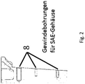
- the gradation of the screw-on slugs 8, resulting from the processing slope according to 1 results is in 2 shown.
- the oil pan sealing surface 9 is arranged at the lower end of the crankcase 1 .
- An exhaust gas recirculation (EGR) channel 10 is arranged in the upper area of the crankcase 1 .
- EGR exhaust gas recirculation
- EGR cooler mount 11 At the same level, to the left of EGR duct 10, is the EGR cooler mount 11. Below the EGR duct 10 and the EGR cooler mount 11 is the starter mount 12. According to the invention, it is located diagonally above the EGR duct on one end face of the Crankcase 1 a nose-like Accumulation of material in the area where the gear wheel passes through to the camshaft 13, which is adjacent to the cylinder head gasket surface 14.
- the cover or gear box 3 shows a cylinder crankcase 1 with a passage for the gear wheel to the camshaft 2.
- the cover or gear box 3 is located on the in 1 illustrated processing of the sealing surface to the timing case cover 4, wherein the timing case cover 3 has a sealing counter-contour on the timing case cover 5, which is in the Figures 6a and 6b to be shown.
- the gear case cover can be in one piece 6 or in two pieces 7, which is also in the Figures 6a and 6b you can see.
- the gradation of the screw-on slugs 8, resulting from the processing slope according to 1 results is in 2 shown and is used to connect the cylinder crankcase 1 and gear case cover 3.
- the oil pan sealing surface 9 is arranged at the lower end of the crankcase 1.
- An exhaust gas recirculation (EGR) channel 10 is arranged in the upper area of the crankcase 1 below the cylinder head gasket surface 14 .
- EGR exhaust gas recirculation
- the EGR cooler mount 11 At the same height, to the left of EGR channel 10 and below the cylinder head gasket surface 14, is the EGR cooler mount 11.
- the starter mount 12 Below the EGR channel 10 and the EGR cooler mount 11 is the starter mount 12. Diagonally above the EGR channel on one On the front side of the crankcase 1 there is a nose-like accumulation of material in the area where the gear wheel passes through to the camshaft 13 , which adjoins the cylinder head gasket surface 14 .
- Figure 4a 1 is a plan view of the crankcase 1 according to FIG 1 from below onto the split oil pan sealing surface 9 with the crankshaft 19 mounted (shrunk).
- Figure 4b shows a plan view of the crankcase 1 according to FIG 1 from below onto the closed oil pan sealing surface 9 with a built (screwed) crankshaft 18 revealed.
- figure 5 a represents a plan view of the crankcase according to FIG Figure 4a , b from below onto the oil pan sealing surface 9 with the mounted timing case cover 3, which is in two parts 7, and with a split oil pan flange.
- Figure 5b Figure 1 shows a plan view of the crankcase according to Figure 4a , b from below onto the oil pan sealing surface 9 without the gear case cover 3 mounted and with the oil pan flange 9 closed.
- the gear case cover 3 has a sealing counter-contour on the gear case cover 5, which is in the Figures 6a and 6b to be shown.
- the timing case covers can be in one piece 6 or in two pieces 7 .
Description
Die Erfindung betrifft eine Brennkraftmaschine mit einem Zylinderkurbelgehäuse und einem Anschlussgehäuse.The invention relates to an internal combustion engine with a cylinder crankcase and a connection housing.
Aus der
Die
Ausgehend vom oben beschriebenen Stand der Technik liegt der Erfindung die Aufgabe zugrunde, diesen weiterzuentwickeln.Proceeding from the prior art described above, the object of the invention is to develop it further.
Die Aufgabe wird dadurch gelöst, dass ein Kurbelgehäuse für eine Brennkraftmaschine geschaffen wird, mit wenigstens einem Ölwannenflansch und einteiliger Kurbelwelle, wobei wenigstens eine Stirnseite des Kurbelgehäuses, an der beispielsweise der Rädertrieb angeordnet ist, eine Bearbeitung der Dichtfläche zum Räderkastendeckel hin aufweist, die in einem Winkel von etwa 4° zur Senkrechten bezüglich der Ölwannenflanschfläche angeordnet ist. Hierbei ist von Vorteil, dass sich die Länge des Kurbelgehäuses insgesamt verringert, was auch Auswirkungen auf die Kosten hat.The object is achieved in that a crankcase for an internal combustion engine is created, with at least one oil pan flange and a one-piece crankshaft, with at least one end face of the crankcase, on which the wheel drive is arranged, for example, having a machining of the sealing surface towards the timing case cover, which in a Angle of about 4 ° to the vertical with respect to the oil pan flange surface is arranged. The advantage here is that the overall length of the crankcase is reduced, which also has an impact on costs.
Weiter ist vorgesehen, dass das Kurbelgehäuse einen Deckel beziehungsweise einen Räderkasten aufweist, der auf der Bearbeitung der Dichtfläche zum Räderkastendeckel, die in einem Winkel von etwa 4° zur Senkrechten bezüglich der Ölwannenflanschfläche angeordnet ist, lösbar befestigt angeordnet ist.It is also provided that the crankcase has a cover or a gear case that is releasably attached to the processing of the sealing surface for the gear case cover, which is arranged at an angle of about 4° to the vertical with respect to the oil pan flange surface.
Andere erfindungsgemäße Ausgestaltungen ergeben sich aus den Unteransprüchen.Other configurations according to the invention result from the dependent claims.
In den Zeichnungen werden bevorzugte Ausführungsbeispiele dargestellt, es zeigen:
- Fig. 1
- eine Seitenansicht eines Kurbelgehäuses mit 4° Schräge für den Räderkasten
- Fig. 2
- Bearbeitung der Dichtfläche zum Räderkastendeckel samt Gewindebohrungen zur Aufnahme des SAE-Gehäuses
- Fig. 3
- Seitenansicht eines Kurbelgehäuses mit 4° Schräge mit Räderkasten gemäß
Fig.1 - Fig. 4a, b
- Draufsicht auf das Kurbelgehäuse gemäß
Fig. 1 von unten auf die Ölwannendichtungsfläche mit montierter Kurbelwelle - Fig. 5a, b
- Draufsicht auf das Kurbelgehäuse gemäß
Fig. 4 von unten auf die Ölwannendichtungsfläche mit montiertem Räderkastendeckel - Fig. 6a
- einteiligen Räderkastendeckel
- Fig. 6b
- zweiteiligen Räderkastendeckel
- 1
- a side view of a crankcase with a 4° slant for the gear housing
- 2
- Machining of the sealing surface for the timing case cover, including threaded holes for accommodating the SAE housing
- 3
- Side view of a crankcase with a 4° slant with gear box according to
Fig.1 - Fig. 4a, b
- Top view of the crankcase according to
1 from below onto the oil pan sealing surface with the crankshaft fitted - Fig. 5a, b
- Top view of the crankcase according to
4 from below onto the oil sump sealing surface with mounted timing case cover - Figure 6a
- one-piece timing case cover
- Figure 6b
- two-piece timing case cover
Bei der Entwicklung von Brennkraftmaschinen wird großer Wert auf die Kompaktheit dieser Motoren gelegt. Insbesondere die Länge des Motors ist entscheidend, um die Geräte, in die dieser Motor eingebaut werden soll, kompakt zu halten. Ein Kriterium für die Motorlänge ist das Zylinderkurbelgehäuse und die Anbringung der Ölwanne bzw. deren Abdichtung zum Zylinderkurbelgehäuse. Insbesondere bei Motoren mit oben liegender Nockenwelle und Antrieb dieser mittels Zahnräder ist mitbestimmend für die Ölwannendichtfläche und damit für die Motorlänge der Zahnradtrieb.When developing internal combustion engines, great importance is attached to the compactness of these engines. In particular, the length of the motor is crucial in order to keep the devices in which this motor is to be installed compact. A criterion for the engine length is the cylinder crankcase and the attachment of the oil pan or its sealing to the cylinder crankcase. Particularly in engines with an overhead camshaft and these being driven by gears, the gear drive is a co-determinant for the oil sump sealing surface and thus for the engine length.
Das Zylinderkurbelgehäuse (1) hat für das Zahnrad zur im Zylinderkopf gelagerten Nockenwelle einen abgedichteten Durchtritt (2). Die anderen kurbelgehäuseseitigen Zahnräder werden über einen Deckel/Räderkasten (3) abgedeckt. Die Ölwannendichtung erfolgt dann über das Kurbelgehäuse und den Deckel. Es gibt Lösungen, bei denen auf den dichtungsumbauten Balkon zum Zylinderkopf verzichtet werden kann, in dem man einen Deckel/Räderkasten ausbildet, der sowohl zum Zylinderkopf, als auch zur Ölwanne abdichtet. Das Toleranzproblem, das daraus entsteht, nämlich die Höhe des Zylinderkurbelgehäuses muss der Höhe dieses Räderkastens entsprechen, da andererseits ein Dichtsprung an einer der beiden abzudichtenden Flächen entsteht, ist bisher nicht gelöst. Es gibt Konstruktionen, die ein Kurbelgehäuse aufweist, das mit einem unten umlaufenden Rand versehen ist. Letztere Lösung baut sehr kurz, hat aber den Nachteil, dass die Kurbelwelle, bedingt durch den umlaufenden Rand des Zylinderkurbelgehäuses, so kurz baut, dass diese mit Verlängerungsbauteilen, die den Durchtritt durch die Zylinderkurbelgehäusewand überbrücken, bestückt werden muss, um die Verbindung mit z. B. Zahnräder, Schwungrad und weiteren Anbauteilen zu ermöglichen.The cylinder crankcase (1) has a sealed passage (2) for the gear wheel to the camshaft mounted in the cylinder head. The other gears on the crankcase side are covered by a cover/gear case (3). The oil pan seal is then made via the crankcase and the cover. There are solutions in which the seal-converted balcony to the cylinder head can be dispensed with by forming a cover/wheel case that seals both the cylinder head and the oil pan. The tolerance problem that arises from this, namely the height of the cylinder crankcase must correspond to the height of this gear case, since on the other hand a sealing crack occurs on one of the two surfaces to be sealed, has not yet been solved. There are constructions that have a crankcase that is provided with a peripheral rim at the bottom. The latter solution is very short, but has the disadvantage that the crankshaft, due to the surrounding edge of the cylinder block, is so short that it has to be equipped with extension components that bridge the passage through the cylinder block wall, in order to establish the connection with e.g. B. gears, flywheel and other attachments.
Die vorliegende Lösung ermöglicht es, die Baulänge des Motors zu verringern, ohne die Nachteile der mehrteiligen Kurbelwelle in Kauf nehmen zu müssen. Dies wird erreicht, indem an der Seite des Zylinderkurbelgehäuses, an der der Rädertrieb angeordnet ist, eine Bearbeitung der Dichtfläche zum Räderkastendeckel durchgeführt ist, die unter einem Winkel, z. B. 4°, bezogen auf die Senkrechte zur Ölwannendichtfläche, erfolgt, der so gewählt ist, dass der zum Zylinderkopf erforderliche Durchtritt 2 des Zahnrades abgedichtet bleibt und das Zylinderkurbelgehäuse zur Ölwanne/Ölwannendichtfläche hin stetig kürzer wird 4. Die jetzt an der Ölwanne örtlich fehlende Dichtgegenkontur 5 wird dann von dem Räderkastendeckel gebildet, der den Komplementärwinkel zur Fläche des Zylinderkurbelgehäuses aufweist. Der Räderkastendeckel ist hier einteilig 6 oder zweiteilig 7 mit dem Anschlussgehäuse ausgebildet. Die Befestigungsschrauben und die Zentrierungen des Anschlussgehäuses/Räderkasten sind so ausgebildet, vorteilhafterweise parallel zur Kurbelwellenlängsachse, dass die Fluchtung des Gehäuses zur Mitte Kurbelwelle gegeben ist. Eine Stufung der Anschraubbutzen, die sich aus der Bearbeitungsschräge ergibt, ist möglich 8. Eine Alternative der Befestigungsschrauben ist, die Zentrierbohrung parallel zur Kurbelwellenlängsachse auszubilden und die Befestigungsschrauben senkrecht zur Dichtfläche. Dadurch ist ebenso eine genaue Zentrierung möglich und beim Anschraubvorgang entsteht winkelbedingt keine Querkraft, die eine Verschiebung der Bauteile untereinander bewirken kann und somit die Genauigkeit Anschlussgehäuse zu Mitte Kurbelwelle negativ beeinflussen könnte.The present solution makes it possible to reduce the overall length of the engine without having to accept the disadvantages of the multi-part crankshaft. This is achieved by machining the sealing surface for the timing case cover on the side of the cylinder crankcase on which the gear train is arranged, which is at an angle, e.g. B. 4 °, based on the perpendicular to the oil pan sealing surface, takes place that is chosen is that the
In
In
In
- 11
- Zylinderkurbelgehäusecylinder crankcase
- 22
- Durchtritt für das Zahnrad zur NockenwellePassage for the gear to the camshaft
- 33
- Deckel/Räderkastendeckelcover/wheel case cover
- 44
- Bearbeitung der Dichtfläche zum Deckel/RäderkastendeckelMachining of the sealing surface for the cover/wheel housing cover
- 55
- Dichtgegenkontur am Deckel/RäderkastendeckelSealing contour on the cover/wheel case cover
- 66
- Räderkastendeckel einteiligOne-piece timing case cover
- 77
- Räderkastendeckel zweiteiligTwo-piece timing case cover
- 88th
- Stufung der Anschraubbutzen, die sich aus der Bearbeitungsschräge ergibtStepping of the screw-on slugs, which results from the processing bevel
- 99
- Ölwannendichtungsflächeoil pan sealing surface
- 1010
- AGR-KanalEGR channel
- 1111
- AGR-KühleraufnahmeEGR cooler intake
- 1212
- Anlasseraufnahmestarter mount
- 1313
- nasenartige Materialansammlung im Bereich des Durchtritts des Zahnrads zur NockenwelleNose-like accumulation of material in the area where the gear wheel passes through to the camshaft
- 1414
- Zylinderkopfdichtungsflächecylinder head gasket surface
- 1515
- Dichtungsfläche AGR-KühlerSealing surface EGR cooler
- 1818
- gebaute/geschraubte Kurbelwelle für ein Zylinderkurbelgehäuse mit geschlossenem Ölwannenflanschbuilt/bolted crankshaft for a cylinder crankcase with closed oil pan flange
- 1919
- geschrumpfte Kurbelwelle für ein Zylinderkurbelgehäuse mit geteiltem ÖlflanschShrunk crankshaft for a cylinder crankcase with a split oil flange
Claims (9)
- Crankcase for an internal combustion engine having at least one oil sump flange and a single-piece crankshaft, wherein at least one end side of the crankcase, at which, for example, the gear drive is arranged, has a machined face of the sealing surface facing towards the cover/gear case cover, which machined face is arranged at an angle of approximately 4° to the perpendicular with respect to the oil sump flange surface, characterized in that, on the side facing towards the gear case, approximately in the region of the leadthrough of the toothed gear to the camshaft (2), a lug-like material accumulation (13) is arranged on the cylinder head gasket side (14), which is situated opposite the oil sump flange side (9) of the crankcase.
- Crankcase for an internal combustion engine according to Claim 1, characterized in that said crankcase has a cover/gear case (3) which is arranged in a detachably fastened manner to the machined face of the sealing surface with respect to the gear case cover, which machined face is arranged at an angle of approximately 4° to the perpendicular with respect to the oil sump flange surface.
- Crankcase for an internal combustion engine according to Claim 1, characterized in that the cover/gear case (3) is fastened to the crankcase by means of the threaded bores 8, which are arranged in the crankcase, and the corresponding screws.
- Crankcase for an internal combustion engine according to one or more of the preceding claims, characterized in that the cover/gear case (3) has a corresponding machined face of the sealing surface, with an angle of approximately 4° to the perpendicular with respect to the oil sump flange surface, for the purposes of sealed connection to the end side of the crankcase (1) .
- Crankcase for an internal combustion engine according to one or more of the preceding claims, characterized in that the crankcase (1) has at least one integrated exhaust-gas recirculation cooler (11).
- Crankcase for an internal combustion according to one or more of the preceding claims,
characterized in that the crankcase (1) has at least one exhaust-gas recirculation channel (10). - Crankcase for an internal combustion engine according to one or more of the preceding claims, characterized in that the lug-like material accumulation (13) is arranged substantially between the upper delimitation of the EGR channel (10) and the cylinder head gasket side.
- Crankcase for an internal combustion engine according to one or more of the preceding claims, characterized in that the machined face of the sealing surface facing towards the gear case cover (4), which machined face is arranged at an angle of approximately 4° to the perpendicular with respect to the oil sump flange surface of the crankcase (9), is arranged between the oil sump flange surface and the lug-like material accumulation (13).
- Internal combustion engine having a cylinder crankcase and a connection housing according to one or more of the preceding claims.
Priority Applications (1)
| Application Number | Priority Date | Filing Date | Title |
|---|---|---|---|
| PL17000589T PL3242009T3 (en) | 2016-05-04 | 2017-04-07 | Internal combustion engine comprising a cylinder crankcase and a connection housing |
Applications Claiming Priority (1)
| Application Number | Priority Date | Filing Date | Title |
|---|---|---|---|
| DE102016005388.7A DE102016005388A1 (en) | 2016-05-04 | 2016-05-04 | Internal combustion engine with a cylinder crankcase and a connection housing |
Publications (2)
| Publication Number | Publication Date |
|---|---|
| EP3242009A1 EP3242009A1 (en) | 2017-11-08 |
| EP3242009B1 true EP3242009B1 (en) | 2022-01-19 |
Family
ID=58501252
Family Applications (1)
| Application Number | Title | Priority Date | Filing Date |
|---|---|---|---|
| EP17000589.6A Active EP3242009B1 (en) | 2016-05-04 | 2017-04-07 | Internal combustion engine comprising a cylinder crankcase and a connection housing |
Country Status (4)
| Country | Link |
|---|---|
| EP (1) | EP3242009B1 (en) |
| DE (1) | DE102016005388A1 (en) |
| ES (1) | ES2907653T3 (en) |
| PL (1) | PL3242009T3 (en) |
Family Cites Families (9)
| Publication number | Priority date | Publication date | Assignee | Title |
|---|---|---|---|---|
| JPH08151955A (en) * | 1994-11-29 | 1996-06-11 | Daihatsu Motor Co Ltd | Seal structure for cylinder head |
| JP3633098B2 (en) * | 1996-04-08 | 2005-03-30 | スズキ株式会社 | Chain cover mounting structure for internal combustion engines |
| DE19855562C1 (en) | 1998-12-02 | 2000-05-31 | Mtu Friedrichshafen Gmbh | Crankcase |
| DE10220838C1 (en) | 2002-05-08 | 2003-12-18 | Porsche Ag | Internal combustion engine |
| DE102004023540A1 (en) * | 2004-05-13 | 2005-12-01 | Deutz Ag | Internal combustion engine has distribution pipe constructed in one piece with cylinder head and may be constructed in one piece with fresh gas line |
| DE102004049030B4 (en) * | 2004-10-08 | 2008-09-11 | Audi Ag | Arrangement of a timing case cover |
| DE102005059006A1 (en) * | 2005-12-08 | 2007-06-14 | Deutz Ag | Exhaust gas recirculation (EGR) system for loaded- or suction-type internal combustion (IC) engine, directly connects exhaust gas cooler with control valve housing, with coolant line connection located in-between |
| DE102013213773A1 (en) * | 2012-07-19 | 2014-01-23 | GM Global Technology Operations, LLC (n.d. Ges. d. Staates Delaware) | Housing for internal combustion engine, has asymmetric surface areas arranged around circular edge, where each asymmetric surface area exhibits surface outline, which differs from surface outlines of other surface area |
| DE102013020944A1 (en) * | 2013-12-12 | 2014-08-14 | Daimler Ag | Internal combustion engine for motor car, has first sealing surface for sealing against steering box cover and second sealing surface for sealing against crankshaft housing, where sealing surfaces include inner angle |
-
2016
- 2016-05-04 DE DE102016005388.7A patent/DE102016005388A1/en not_active Ceased
-
2017
- 2017-04-07 EP EP17000589.6A patent/EP3242009B1/en active Active
- 2017-04-07 PL PL17000589T patent/PL3242009T3/en unknown
- 2017-04-07 ES ES17000589T patent/ES2907653T3/en active Active
Also Published As
| Publication number | Publication date |
|---|---|
| EP3242009A1 (en) | 2017-11-08 |
| DE102016005388A1 (en) | 2017-11-09 |
| PL3242009T3 (en) | 2022-05-09 |
| ES2907653T3 (en) | 2022-04-25 |
Similar Documents
| Publication | Publication Date | Title |
|---|---|---|
| EP0975869B1 (en) | Fuel injection system for an internal combustion engine with a common rail | |
| DE69909703T2 (en) | Anti-foam sheet of an internal combustion engine | |
| EP2980374A1 (en) | Ventilation device with oil separator | |
| DE3050893C2 (en) | ||
| EP0735262B1 (en) | Cylinder block for combustion engine | |
| EP1799988A1 (en) | Arrangement of a timing case cover | |
| DE102018116664A1 (en) | CYLINDER HEAD CAP STRUCTURE FOR ONE ENGINE | |
| DE3125077A1 (en) | TWO-CYLINDER FOUR-STOCK BOXER ENGINE, ESPECIALLY DRIVE WIND AIR-COOLED FOR MOTORCYCLES | |
| DE4029408C2 (en) | Lube oil heat exchanger of an internal combustion engine | |
| DE4242265C1 (en) | Valve cover | |
| EP0251159B1 (en) | Return line for leak gas from a crank case | |
| DE10033367C2 (en) | Internal combustion engine, in particular for motorcycles | |
| EP3242009B1 (en) | Internal combustion engine comprising a cylinder crankcase and a connection housing | |
| DE19757286A1 (en) | Cylinder head for single-cylinder internal combustion engine | |
| DE102011008093B4 (en) | Lubrication system for engines equipped with a turbocharger | |
| DE2547992A1 (en) | CYLINDER HEAD FOR COMBUSTION MACHINES WITH COMPRESSION IGNITION | |
| DE60123350T2 (en) | Cylinder head cover for a combustion engine | |
| DE102011117503A1 (en) | Combustion Engine | |
| DE3401266A1 (en) | DEVICE FOR PROTECTING THE IGNITOR DEVICE ON A MULTI-CYLINDER INTERNAL COMBUSTION ENGINE | |
| DE4406986A1 (en) | Reciprocating internal combustion engine | |
| DE112015000036B4 (en) | Mounting structure for a fuel pump | |
| DE19548329C2 (en) | Otto combustion engine with fuel injection valve | |
| DE202005013734U1 (en) | Venting module for an internal combustion engine | |
| DE102014101940A1 (en) | An engine having a PCV trap inlet shielded from a head seal geometry | |
| DE19732422A1 (en) | Chain cover for internal combustion engine |
Legal Events
| Date | Code | Title | Description |
|---|---|---|---|
| PUAI | Public reference made under article 153(3) epc to a published international application that has entered the european phase |
Free format text: ORIGINAL CODE: 0009012 |
|
| STAA | Information on the status of an ep patent application or granted ep patent |
Free format text: STATUS: THE APPLICATION HAS BEEN PUBLISHED |
|
| AK | Designated contracting states |
Kind code of ref document: A1 Designated state(s): AL AT BE BG CH CY CZ DE DK EE ES FI FR GB GR HR HU IE IS IT LI LT LU LV MC MK MT NL NO PL PT RO RS SE SI SK SM TR |
|
| AX | Request for extension of the european patent |
Extension state: BA ME |
|
| STAA | Information on the status of an ep patent application or granted ep patent |
Free format text: STATUS: REQUEST FOR EXAMINATION WAS MADE |
|
| 17P | Request for examination filed |
Effective date: 20180508 |
|
| RBV | Designated contracting states (corrected) |
Designated state(s): AL AT BE BG CH CY CZ DE DK EE ES FI FR GB GR HR HU IE IS IT LI LT LU LV MC MK MT NL NO PL PT RO RS SE SI SK SM TR |
|
| GRAP | Despatch of communication of intention to grant a patent |
Free format text: ORIGINAL CODE: EPIDOSNIGR1 |
|
| STAA | Information on the status of an ep patent application or granted ep patent |
Free format text: STATUS: GRANT OF PATENT IS INTENDED |
|
| INTG | Intention to grant announced |
Effective date: 20210825 |
|
| GRAS | Grant fee paid |
Free format text: ORIGINAL CODE: EPIDOSNIGR3 |
|
| STAA | Information on the status of an ep patent application or granted ep patent |
Free format text: STATUS: GRANT OF PATENT IS INTENDED |
|
| GRAA | (expected) grant |
Free format text: ORIGINAL CODE: 0009210 |
|
| STAA | Information on the status of an ep patent application or granted ep patent |
Free format text: STATUS: THE PATENT HAS BEEN GRANTED |
|
| AK | Designated contracting states |
Kind code of ref document: B1 Designated state(s): AL AT BE BG CH CY CZ DE DK EE ES FI FR GB GR HR HU IE IS IT LI LT LU LV MC MK MT NL NO PL PT RO RS SE SI SK SM TR |
|
| REG | Reference to a national code |
Ref country code: GB Ref legal event code: FG4D Free format text: NOT ENGLISH |
|
| REG | Reference to a national code |
Ref country code: CH Ref legal event code: EP |
|
| REG | Reference to a national code |
Ref country code: DE Ref legal event code: R096 Ref document number: 502017012457 Country of ref document: DE |
|
| REG | Reference to a national code |
Ref country code: AT Ref legal event code: REF Ref document number: 1463923 Country of ref document: AT Kind code of ref document: T Effective date: 20220215 |
|
| REG | Reference to a national code |
Ref country code: IE Ref legal event code: FG4D Free format text: LANGUAGE OF EP DOCUMENT: GERMAN |
|
| REG | Reference to a national code |
Ref country code: NL Ref legal event code: FP |
|
| REG | Reference to a national code |
Ref country code: ES Ref legal event code: FG2A Ref document number: 2907653 Country of ref document: ES Kind code of ref document: T3 Effective date: 20220425 |
|
| REG | Reference to a national code |
Ref country code: LT Ref legal event code: MG9D |
|
| PG25 | Lapsed in a contracting state [announced via postgrant information from national office to epo] |
Ref country code: SE Free format text: LAPSE BECAUSE OF FAILURE TO SUBMIT A TRANSLATION OF THE DESCRIPTION OR TO PAY THE FEE WITHIN THE PRESCRIBED TIME-LIMIT Effective date: 20220119 Ref country code: RS Free format text: LAPSE BECAUSE OF FAILURE TO SUBMIT A TRANSLATION OF THE DESCRIPTION OR TO PAY THE FEE WITHIN THE PRESCRIBED TIME-LIMIT Effective date: 20220119 Ref country code: PT Free format text: LAPSE BECAUSE OF FAILURE TO SUBMIT A TRANSLATION OF THE DESCRIPTION OR TO PAY THE FEE WITHIN THE PRESCRIBED TIME-LIMIT Effective date: 20220519 Ref country code: NO Free format text: LAPSE BECAUSE OF FAILURE TO SUBMIT A TRANSLATION OF THE DESCRIPTION OR TO PAY THE FEE WITHIN THE PRESCRIBED TIME-LIMIT Effective date: 20220419 Ref country code: LT Free format text: LAPSE BECAUSE OF FAILURE TO SUBMIT A TRANSLATION OF THE DESCRIPTION OR TO PAY THE FEE WITHIN THE PRESCRIBED TIME-LIMIT Effective date: 20220119 Ref country code: HR Free format text: LAPSE BECAUSE OF FAILURE TO SUBMIT A TRANSLATION OF THE DESCRIPTION OR TO PAY THE FEE WITHIN THE PRESCRIBED TIME-LIMIT Effective date: 20220119 Ref country code: BG Free format text: LAPSE BECAUSE OF FAILURE TO SUBMIT A TRANSLATION OF THE DESCRIPTION OR TO PAY THE FEE WITHIN THE PRESCRIBED TIME-LIMIT Effective date: 20220419 |
|
| PG25 | Lapsed in a contracting state [announced via postgrant information from national office to epo] |
Ref country code: LV Free format text: LAPSE BECAUSE OF FAILURE TO SUBMIT A TRANSLATION OF THE DESCRIPTION OR TO PAY THE FEE WITHIN THE PRESCRIBED TIME-LIMIT Effective date: 20220119 Ref country code: GR Free format text: LAPSE BECAUSE OF FAILURE TO SUBMIT A TRANSLATION OF THE DESCRIPTION OR TO PAY THE FEE WITHIN THE PRESCRIBED TIME-LIMIT Effective date: 20220420 Ref country code: FI Free format text: LAPSE BECAUSE OF FAILURE TO SUBMIT A TRANSLATION OF THE DESCRIPTION OR TO PAY THE FEE WITHIN THE PRESCRIBED TIME-LIMIT Effective date: 20220119 |
|
| PG25 | Lapsed in a contracting state [announced via postgrant information from national office to epo] |
Ref country code: IS Free format text: LAPSE BECAUSE OF FAILURE TO SUBMIT A TRANSLATION OF THE DESCRIPTION OR TO PAY THE FEE WITHIN THE PRESCRIBED TIME-LIMIT Effective date: 20220519 |
|
| REG | Reference to a national code |
Ref country code: DE Ref legal event code: R097 Ref document number: 502017012457 Country of ref document: DE |
|
| PG25 | Lapsed in a contracting state [announced via postgrant information from national office to epo] |
Ref country code: SM Free format text: LAPSE BECAUSE OF FAILURE TO SUBMIT A TRANSLATION OF THE DESCRIPTION OR TO PAY THE FEE WITHIN THE PRESCRIBED TIME-LIMIT Effective date: 20220119 Ref country code: SK Free format text: LAPSE BECAUSE OF FAILURE TO SUBMIT A TRANSLATION OF THE DESCRIPTION OR TO PAY THE FEE WITHIN THE PRESCRIBED TIME-LIMIT Effective date: 20220119 Ref country code: RO Free format text: LAPSE BECAUSE OF FAILURE TO SUBMIT A TRANSLATION OF THE DESCRIPTION OR TO PAY THE FEE WITHIN THE PRESCRIBED TIME-LIMIT Effective date: 20220119 Ref country code: EE Free format text: LAPSE BECAUSE OF FAILURE TO SUBMIT A TRANSLATION OF THE DESCRIPTION OR TO PAY THE FEE WITHIN THE PRESCRIBED TIME-LIMIT Effective date: 20220119 Ref country code: DK Free format text: LAPSE BECAUSE OF FAILURE TO SUBMIT A TRANSLATION OF THE DESCRIPTION OR TO PAY THE FEE WITHIN THE PRESCRIBED TIME-LIMIT Effective date: 20220119 Ref country code: CZ Free format text: LAPSE BECAUSE OF FAILURE TO SUBMIT A TRANSLATION OF THE DESCRIPTION OR TO PAY THE FEE WITHIN THE PRESCRIBED TIME-LIMIT Effective date: 20220119 |
|
| PLBE | No opposition filed within time limit |
Free format text: ORIGINAL CODE: 0009261 |
|
| STAA | Information on the status of an ep patent application or granted ep patent |
Free format text: STATUS: NO OPPOSITION FILED WITHIN TIME LIMIT |
|
| PG25 | Lapsed in a contracting state [announced via postgrant information from national office to epo] |
Ref country code: AL Free format text: LAPSE BECAUSE OF FAILURE TO SUBMIT A TRANSLATION OF THE DESCRIPTION OR TO PAY THE FEE WITHIN THE PRESCRIBED TIME-LIMIT Effective date: 20220119 |
|
| REG | Reference to a national code |
Ref country code: CH Ref legal event code: PL |
|
| 26N | No opposition filed |
Effective date: 20221020 |
|
| REG | Reference to a national code |
Ref country code: BE Ref legal event code: MM Effective date: 20220430 |
|
| PG25 | Lapsed in a contracting state [announced via postgrant information from national office to epo] |
Ref country code: MC Free format text: LAPSE BECAUSE OF FAILURE TO SUBMIT A TRANSLATION OF THE DESCRIPTION OR TO PAY THE FEE WITHIN THE PRESCRIBED TIME-LIMIT Effective date: 20220119 Ref country code: LU Free format text: LAPSE BECAUSE OF NON-PAYMENT OF DUE FEES Effective date: 20220407 Ref country code: LI Free format text: LAPSE BECAUSE OF NON-PAYMENT OF DUE FEES Effective date: 20220430 Ref country code: CH Free format text: LAPSE BECAUSE OF NON-PAYMENT OF DUE FEES Effective date: 20220430 |
|
| PG25 | Lapsed in a contracting state [announced via postgrant information from national office to epo] |
Ref country code: SI Free format text: LAPSE BECAUSE OF FAILURE TO SUBMIT A TRANSLATION OF THE DESCRIPTION OR TO PAY THE FEE WITHIN THE PRESCRIBED TIME-LIMIT Effective date: 20220119 Ref country code: BE Free format text: LAPSE BECAUSE OF NON-PAYMENT OF DUE FEES Effective date: 20220430 |
|
| PG25 | Lapsed in a contracting state [announced via postgrant information from national office to epo] |
Ref country code: IE Free format text: LAPSE BECAUSE OF NON-PAYMENT OF DUE FEES Effective date: 20220407 |
|
| PGFP | Annual fee paid to national office [announced via postgrant information from national office to epo] |
Ref country code: PL Payment date: 20230330 Year of fee payment: 7 |
|
| PGFP | Annual fee paid to national office [announced via postgrant information from national office to epo] |
Ref country code: NL Payment date: 20230419 Year of fee payment: 7 |
|
| P01 | Opt-out of the competence of the unified patent court (upc) registered |
Effective date: 20230530 |
|
| PGFP | Annual fee paid to national office [announced via postgrant information from national office to epo] |
Ref country code: IT Payment date: 20230420 Year of fee payment: 7 Ref country code: FR Payment date: 20230424 Year of fee payment: 7 Ref country code: ES Payment date: 20230627 Year of fee payment: 7 Ref country code: DE Payment date: 20230606 Year of fee payment: 7 |
|
| PGFP | Annual fee paid to national office [announced via postgrant information from national office to epo] |
Ref country code: TR Payment date: 20230405 Year of fee payment: 7 Ref country code: AT Payment date: 20230420 Year of fee payment: 7 |
|
| PGFP | Annual fee paid to national office [announced via postgrant information from national office to epo] |
Ref country code: GB Payment date: 20230419 Year of fee payment: 7 |
|
| PG25 | Lapsed in a contracting state [announced via postgrant information from national office to epo] |
Ref country code: HU Free format text: LAPSE BECAUSE OF FAILURE TO SUBMIT A TRANSLATION OF THE DESCRIPTION OR TO PAY THE FEE WITHIN THE PRESCRIBED TIME-LIMIT; INVALID AB INITIO Effective date: 20170407 |
|
| PG25 | Lapsed in a contracting state [announced via postgrant information from national office to epo] |
Ref country code: MK Free format text: LAPSE BECAUSE OF FAILURE TO SUBMIT A TRANSLATION OF THE DESCRIPTION OR TO PAY THE FEE WITHIN THE PRESCRIBED TIME-LIMIT Effective date: 20220119 Ref country code: CY Free format text: LAPSE BECAUSE OF FAILURE TO SUBMIT A TRANSLATION OF THE DESCRIPTION OR TO PAY THE FEE WITHIN THE PRESCRIBED TIME-LIMIT Effective date: 20220119 |