EP3241981B1 - Packer setting and/or unsetting - Google Patents
Packer setting and/or unsetting Download PDFInfo
- Publication number
- EP3241981B1 EP3241981B1 EP17173122.7A EP17173122A EP3241981B1 EP 3241981 B1 EP3241981 B1 EP 3241981B1 EP 17173122 A EP17173122 A EP 17173122A EP 3241981 B1 EP3241981 B1 EP 3241981B1
- Authority
- EP
- European Patent Office
- Prior art keywords
- dog
- sliding
- packer
- mandrel
- stationary housing
- Prior art date
- Legal status (The legal status is an assumption and is not a legal conclusion. Google has not performed a legal analysis and makes no representation as to the accuracy of the status listed.)
- Active
Links
- 238000007789 sealing Methods 0.000 claims description 27
- 238000000034 method Methods 0.000 claims description 10
- 230000006835 compression Effects 0.000 claims description 5
- 238000007906 compression Methods 0.000 claims description 5
- 238000006073 displacement reaction Methods 0.000 claims 5
- 241000282472 Canis lupus familiaris Species 0.000 description 52
- 238000013519 translation Methods 0.000 description 5
- 230000014616 translation Effects 0.000 description 5
- 238000005553 drilling Methods 0.000 description 2
- 239000012530 fluid Substances 0.000 description 2
- 238000004519 manufacturing process Methods 0.000 description 2
- 238000002070 Raman circular dichroism spectroscopy Methods 0.000 description 1
- 238000009844 basic oxygen steelmaking Methods 0.000 description 1
- 229920001971 elastomer Polymers 0.000 description 1
- 239000000806 elastomer Substances 0.000 description 1
- 230000003993 interaction Effects 0.000 description 1
- 230000003068 static effect Effects 0.000 description 1
Images


Classifications
-
- E—FIXED CONSTRUCTIONS
- E21—EARTH DRILLING; MINING
- E21B—EARTH DRILLING, e.g. DEEP DRILLING; OBTAINING OIL, GAS, WATER, SOLUBLE OR MELTABLE MATERIALS OR A SLURRY OF MINERALS FROM WELLS
- E21B23/00—Apparatus for displacing, setting, locking, releasing, or removing tools, packers or the like in the boreholes or wells
- E21B23/06—Apparatus for displacing, setting, locking, releasing, or removing tools, packers or the like in the boreholes or wells for setting packers
-
- E—FIXED CONSTRUCTIONS
- E21—EARTH DRILLING; MINING
- E21B—EARTH DRILLING, e.g. DEEP DRILLING; OBTAINING OIL, GAS, WATER, SOLUBLE OR MELTABLE MATERIALS OR A SLURRY OF MINERALS FROM WELLS
- E21B33/00—Sealing or packing boreholes or wells
-
- E—FIXED CONSTRUCTIONS
- E21—EARTH DRILLING; MINING
- E21B—EARTH DRILLING, e.g. DEEP DRILLING; OBTAINING OIL, GAS, WATER, SOLUBLE OR MELTABLE MATERIALS OR A SLURRY OF MINERALS FROM WELLS
- E21B33/00—Sealing or packing boreholes or wells
- E21B33/02—Surface sealing or packing
- E21B33/08—Wipers; Oil savers
- E21B33/085—Rotatable packing means, e.g. rotating blow-out preventers
-
- E—FIXED CONSTRUCTIONS
- E21—EARTH DRILLING; MINING
- E21B—EARTH DRILLING, e.g. DEEP DRILLING; OBTAINING OIL, GAS, WATER, SOLUBLE OR MELTABLE MATERIALS OR A SLURRY OF MINERALS FROM WELLS
- E21B2200/00—Special features related to earth drilling for obtaining oil, gas or water
- E21B2200/06—Sleeve valves
Definitions
- Oilfield operations may be performed in order to extract fluids from the earth (including subsea).
- pressure control equipment may be placed near the surface of the earth.
- the pressure control equipment may control the pressure in the wellbore while drilling, completing and producing the wellbore.
- the pressure control equipment may include blowout preventers (BOP), rotating control devices (RCD), and the like.
- the rotating control device or RCD is a drill-through device with a rotating seal that contacts and seals against the drill string (drill pipe, casing, drill collars, Kelly, etc.) for the purposes of controlling the pressure or fluid flow to the surface.
- drill string drill pipe, casing, drill collars, Kelly, etc.
- US patent number 8,322,432 entitled “Subsea Internal Riser Rotating Control Device System and Method", U.S. Application no. 12/643,093, filed December 21, 2009 and published July 15, 2010; and US patent publication number US 2012/0318496 entitled “Subsea Internal Riser Rotating Control Head Seal Assembly", U.S. Application no.
- Conventional sealing systems for RCD's include a drill string sealing element which seals against the rotating drill string and several external seals which seal against a fixed flanged housing.
- the flanged housing is part of stackup below the rig.
- the RCD external housing is held fixed to the flanged housing by hydraulic or mechanical means. Downhole pressure is contained via the internal drill string sealing element and the external static seals on the housing.
- Conventional packers have external sealing elements that are hydraulically set via downhole pressure.
- the packer sealing element is held in the set position via a body lock ring.
- Pressure below the packer is contained via the packer element sealing against the casing.
- To unset the packer the housing lock ring is released via a shear ring and a collet by pulling up or setting down load on the packer.
- Conventional packers can only be set and unset once and then they have to be pulled out of the hole for redress due to the shear ring use.
- packer elements are elastomers and have limited use they have to be replaced periodically making it very costly or impossible to retrieve from, for example, a flanged housing, subsea riser, or casing.
- This seal system uses a packer type sealing element in one embodiment on the external housing of a RCD however it is set and unset mechanically instead of hydraulically.
- the RCD can therefore be set anywhere there is a locking profile, e.g. flanged housing (in a stackup rig configuration), subsea riser or in casing.
- the RCD housing has external biased out latch locking dogs that engage a profile in the flanged housing, riser or casing. Once the latch locking dogs engage the profile the RCD housing is locked in place from moving further downhole.
- the mandrel inside the RCD housing is locked to the drill string via mechanical means. As the drill string is lowered the mandrel pushes out a different set of dogs that push against the packer housing which sets the packer(s). Now the downhole pressure is held in place by the drill string sealing element and the external packer(s) on the RCD housing. To unset the packer(s) the translating mandrel is pulled up and the stored energy of the packer(s) will push the packer housing and therefore the dogs back in radially.
- the packer(s) can be set and unset multiple times as long as the packer(s) is not damaged; the packer(s) can be easily replaced and then reinstalled; and/or the packer(s) can be deployed in a subsea RCD.
- linear movement via a sliding mandrel configured to translate axially is converted into radial movement to compress a packer.
- the packer is configured to seal an item of oilfield equipment typically in a subsea environment.
- the packer may also be used to return or reverse the radial movement and/or the linear movement.
- radial and radially include directions inward toward (or outward away from) the center axial direction of the drill string or item of oilfield equipment but not limited to directions perpendicular to such axial direction or running directly through the center. Rather such directions, although including perpendicular and toward (or away from) the center, also include those transverse and/or off center yet moving inward (or outward), across or against the surface of an outer sleeve of item of oilfield equipment to be engaged.
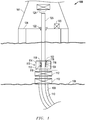
- Figure 1 depicts a schematic view of a wellsite 100 with a rig 101.
- the wellsite 100 has a seal system 102 for sealing to an item or piece of oilfield equipment 104.
- the wellsite 100 is an offshore wellsite although other types of wellsites are applicable.
- the wellsite 100 may have a wellbore 106 formed in the sea floor 108 and lined with a casing 110.
- At the sea floor 108 one or more pressure control devices 112 may control pressure in the wellbore 106.
- the pressure control devices 112 may include, but are not limited to, BOPs, RCDs 113, and the like.
- the seal system 102 is shown and described herein as being located in a housing 114.
- the seal system 102 may have one or more seal member(s)/packer(s) 116 configured to engage the oilfield equipment 104.
- the seal system 102 may have one or more actuators 118 configured to drive the seal member 116 into and out of engagement with the oilfield equipment 104.
- the seal system 102 may set and unset the seal member 116 via mechanical movement of a mandrel as will be discussed in more detail below.
- the oilfield equipment 104 may be any suitable equipment that will be sealed with the seal system 102 including, but not limited to, the RCD 113, a drill string, a casing, a production tubing, a sleeve, and the like.
- the seal system 102 may further include one or more sensors 119 configured to identify the status of the seal system 102 and/or to inform the controller 120 that the packer 116 is sealed, not sealed, and/or at an intermediate position.
- the seal system 102 for example, may be incorporated with a subsea RCD 113 and used for sealing against a riser 300 ( Fig. 6 ).
- the wellsite 100 may have a controller 120 for controlling the seal system 102.
- the controller 120 may control and/or obtain information from any suitable system about the wellsite 100 including, but not limited to, the pressure control devices 112, the housing 114, the sensor(s) 119, a gripping apparatus 122, a rotational apparatus 124, and the like.
- the gripping apparatus 122 may be a pair of slips configured to grip a tubular 125 (such as a drill string, a production string, a casing and the like) at a rig floor 126; however, the gripping apparatus 122 may be any suitable gripping device.
- the rotational apparatus 124 is a top drive for supporting and rotating the tubular 125, although it may be any suitable rotational device including, but not limited to, a Kelly, a pipe spinner, and the like.
- the controller 120 may control any suitable equipment about the wellsite 100 including, but not limited to, a draw works, a traveling block, pumps, mud control devices, cementing tools, drilling tools, and the like.
- Figure 2 depicts a longitudinal cross sectional view of the housing 114 having the seal system 102 according to an embodiment.
- the housing 114 has the seal member or packer 116 (in the unset position, i.e. not opposing or sealing against the flanged housing, casing or subsea riser 300) and the one or more actuators 118.
- the actuator 118 (which may for example be mounted below the RCD 113 body) may include, but is not limited to, a sliding mandrel 200, a dog 202, a sliding sleeve 204, a packer ring 206, an engagement portion 208, an outer sleeve 210, and a stationary mandrel, tool body, or stationary housing 212.
- the actuator 118 may be configured to set and unset the sealing member or packer 116 via axial movement of the sliding mandrel 200.
- the axial translation of the sliding mandrel 200 may convert the axial movement into radial movement via the dog 202.
- the dog 202 may then convert the radial translation back into axial movement via the sliding sleeve 204.
- the sliding sleeve 204 may engage the packer ring 206 and thereby compress the packer 116 in order to set the packer 116 as will be discussed in more detail below.
- the sealing member or packer 116 may be any suitable deformable packer sealing member including, but not limited to an elastomeric member, and the like, configured to expand radially outward upon axial compression of the sealing member 116.
- the sliding mandrel 200 may have a setting surface 214 configured to engage the dog 202 in order to set and unset the packer 116.
- the setting surface 214 is located in a profile formed in an outer surface of the sliding mandrel 200.
- the setting surface 214 may be configured to engage a dog setting surface 218.
- the continual axial movement in the setting direction of the sliding mandrel 200 forces the dog 202 to translate radially outward, or away from the sliding mandrel 200.
- the sliding mandrel 200 may be moved in the opposite direction, or unsetting direction.
- the setting surface 214 disengages the dog setting surface 218, the stored energy in the packer 116 may force the packer ring 206 and thereby the sliding sleeve 204 to release and/or unset the packer 116.
- the sliding mandrel 200 may move in the unset and setting direction via mechanical manipulation of the sliding mandrel 200 from the rig 101 or drill string. Further, the sliding mandrel 200 may move via hydraulic, electric, pneumatic power and the like.
- the setting surface 214 may have a relatively small angle ⁇ configured to engage the dog setting surface 218 having a similar angle as ⁇ .
- the small angle ⁇ allows relatively large translations of the sliding mandrel 200 to translate into small outward radial movement of the dog 202. This small radial movement of the dog 202 may gradually set the packer 116 by gradually moving the sliding sleeve 204.
- the setting surface 214 may be a secondary setting surface 216.
- the secondary setting surface 216 may have a larger or steeper angle ⁇ than the small angle ⁇ .
- the larger angle ⁇ of the secondary setting surface 216 may engage a dog secondary setting surface 220.
- the larger angle may move the dog 202 radially away from the sliding mandrel 200 at a faster rate per axial translation of the sliding mandrel 200 than the setting surface. Therefore, the operator may relatively more slowly engage and/or set the packer 116 by moving the sliding mandrel 200 in the setting direction (downhole) and then may relatively more quickly release the packer 116 by moving the sliding mandrel in the unsetting direction with the secondary setting surface 216 engage in the dog secondary setting surface 220.
- the secondary setting surface 216 may be a shoulder configured to engage the dog 202 thereby stopping travel of the sliding mandrel 200.
- the secondary setting surface 216 can be angled in an opposite direction (not shown) arranged in order to pull the dog(s) 202 radially inward.
- the dog(s) 202 could also positively pull the sliding sleeve 204 toward the disengagement position.
- dogs 202 located around the sliding mandrel 200. As shown there are multiple dogs 202 which travel radially though one or more slots 226 in the stationary mandrel 212. Although not shown, the dog 202 may be biased radially inward, or toward the unset position.
- the dog 202 may have a dog actuation surface 222 configured to a sleeve actuation surface 224 on the sliding sleeve 204. As the dog 202 travels radially away from the sliding mandrel 200 the dog actuation surface 222 engages the sleeve actuation surface 224. Continued radial movement of the dog 202 outward moves the sliding sleeve 204 toward the packer ring 206 due to the interaction between the dog actuation surface 222 and the sleeve actuation surface 224. Although not shown, the dog 202 may be biased radially inward, or toward the unset position.
- the dog actuation surface 222 may be locked to the sleeve actuation surface 224 for example with a dove tail configuration in order to positively move the sliding sleeve 204 both toward and away from the packer ring 206.
- the sliding sleeve 204 may travel through an aperture formed between the outer sleeve 210 and the stationary mandrel 212.
- a nose 228 of the sliding sleeve 204 engages the packer ring 206 as the dog(s) 202 actuate the sliding sleeve 204.
- the sliding sleeve 204 then moves the packer ring 206 toward the packer 116 thereby compressing the packer 116 into an actuated position.
- the packer ring 206 may be a full ring around the proximate the packer 116, or may be a partial ring. Further, there may be a second packer ring 206a (see Fig. 4 ) located on the opposite side of the packer 116. The second packer ring 206a may distribute the compression force on the packer 116 from the sliding sleeve 204.
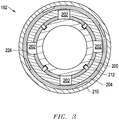
- Figure 3 depicts a top cross section view of the seal system 102 taken through the dogs 202.
- the seal system 102 is in the unactuated, or run in, position.
- the setting surface 214 and/or the secondary setting surface 216 have not moved the dogs 202 toward the sliding sleeve 204.
- there are four dogs 202 configured to move through the slots 226 in the stationary housing 212.
- the packer 116 may be moved to a location to be sealed.
- the packer 116 may be moved into the RCD 113 (as shown, in Figure 1 ) or any other suitable location including, but not limited to, in the wellbore 106, the casing 110, and the like.
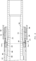
- Figure 4 depicts a longitudinal cross section view of the seal system 102 when the sliding mandrel 200 initially engages the dogs 202 and the packer 116 is still unactuated. As shown, the sliding mandrel 200 has been moved relative to the stationary housing 212 until the setting surface 214 engages the dog setting surface 218.
- Figure 5 depicts a longitudinal cross section of the seal system 102 in an intermediate position between the unactuated and actuated position.
- the setting surface 214 has moved the dog(s) 202 radially outward due to continued axial movement of the sliding mandrel 200.
- the dog actuation surface 222 has engaged the sleeve actuation surface 224 thereby moving the nose 228 of the sliding sleeve 204 into engagement with the packer ring 206.
- the packer ring 206 may be compressing the packer 116 in this position, but the packer 116 may not be fully actuated.
- Figure 6 depicts a longitudinal cross section of the seal system 102 in an actuated position.
- the continued movement of the sliding mandrel 200 has moved the dog(s) 202 and thereby the packer 116 into an actuated, or sealed, position.
- the setting surface 214 has moved the dog(s) 202 to a position outside of an outer surface 600 of the sliding mandrel 200.
- the dog actuation surface 222 has moved the sliding sleeve 204 to an actuated position.
- the packer ring 206 may have moved longitudinally toward the packer 116 thereby compressing the packer 116.
- the compression of the packer 116 may extend the packer 116 radially outward into a sealed or actuated position against a casing or subsea riser 300.
- the outer sleeve 210 may limit the radial movement of the dog(s) 202.
- a sliding mandrel shoulder 601 may engage a limit shoulder 602 of the stationary housing 212 in order to limit the movement of the sliding mandrel 200 (e.g. to prevent the sliding mandrel 200 from moving further downhole). Any downhole pressure from below the packer 116 is translated back to the dog(s) 202 and applies a collapse load against the outer surface 600 of the sliding mandrel 200.
- Figure 7 depicts top cross section view of the seal system 102 in the actuated position taken through the dogs 202. As shown, the dog(s) 202 are shown radially outside of the sliding mandrel 200.
- the seal system 102 may remain in the actuated position until it is desired to remove the seal system 102.
- the sliding mandrel may be moved in the opposite axial direction to the actuation direction.
- the stored energy in the packer 116 may push the packer ring 206, the sliding sleeve 204 and the dog(s) 202 toward the unactuated position.
- Figure 8 is a flow chart depicting a method of sealing an item of oilfield equipment.
- the flow starts at block 800 wherein, the seal system is located proximate a piece of oilfield equipment.
- the flow continues at block 802 wherein, the sliding mandrel 200 is translated axially relative to the tool body of the seal system.
- the sliding mandrel 200 may be translated using mechanical actuation as discussed above.
- the flow continues at block 804 wherein, the seal member 116 is actuated in response to the translation of the sliding mandrel 200.
- the flow continues at block 806 wherein, the item of oilfield equipment 104 is sealed with the seal member 116.
- the flow continues at block 808 wherein, the seal member 116 is removed from the item of PX213610EPA oilfield equipment 104 by moving the sliding mandrel 200 in the opposite direction from the direction it moved during actuation.
Description
- Technical Field: Oilfield operations may be performed in order to extract fluids from the earth (including subsea). When a well site is completed, pressure control equipment may be placed near the surface of the earth. The pressure control equipment may control the pressure in the wellbore while drilling, completing and producing the wellbore. The pressure control equipment may include blowout preventers (BOP), rotating control devices (RCD), and the like.
- The rotating control device or RCD is a drill-through device with a rotating seal that contacts and seals against the drill string (drill pipe, casing, drill collars, Kelly, etc.) for the purposes of controlling the pressure or fluid flow to the surface. For reference to an existing descriptions of a rotating control device incorporating a system for sealing a marine riser having a rotatable tubular, please see
US patent number 8,322,432 entitled "Subsea Internal Riser Rotating Control Device System and Method",U.S. Application no. 12/643,093, filed December 21, 2009 US 2012/0318496 entitled "Subsea Internal Riser Rotating Control Head Seal Assembly",U.S. Application no. 13/597,881, filed August 29, 2012 US 3,991,826A describes a well packer which is set by pressure applied through a tubing string which supports the packer within a surrounding well conduit. - Conventional sealing systems for RCD's include a drill string sealing element which seals against the rotating drill string and several external seals which seal against a fixed flanged housing. The flanged housing is part of stackup below the rig. The RCD external housing is held fixed to the flanged housing by hydraulic or mechanical means. Downhole pressure is contained via the internal drill string sealing element and the external static seals on the housing.
- Conventional packers have external sealing elements that are hydraulically set via downhole pressure. The packer sealing element is held in the set position via a body lock ring. Pressure below the packer is contained via the packer element sealing against the casing. To unset the packer the housing lock ring is released via a shear ring and a collet by pulling up or setting down load on the packer. Conventional packers can only be set and unset once and then they have to be pulled out of the hole for redress due to the shear ring use.
- Since packer elements are elastomers and have limited use they have to be replaced periodically making it very costly or impossible to retrieve from, for example, a flanged housing, subsea riser, or casing. A need exists for a seal system that can be set and retrieved with the RCD instead of being part of the permanent or semi-permanent components (e.g. flanged housing, subsea riser or casing).
- Aspects of the invention are set out in the accompanying claims. This seal system uses a packer type sealing element in one embodiment on the external housing of a RCD however it is set and unset mechanically instead of hydraulically. The RCD can therefore be set anywhere there is a locking profile, e.g. flanged housing (in a stackup rig configuration), subsea riser or in casing.
- In this embodiment the RCD housing has external biased out latch locking dogs that engage a profile in the flanged housing, riser or casing. Once the latch locking dogs engage the profile the RCD housing is locked in place from moving further downhole. The mandrel inside the RCD housing is locked to the drill string via mechanical means. As the drill string is lowered the mandrel pushes out a different set of dogs that push against the packer housing which sets the packer(s). Now the downhole pressure is held in place by the drill string sealing element and the external packer(s) on the RCD housing. To unset the packer(s) the translating mandrel is pulled up and the stored energy of the packer(s) will push the packer housing and therefore the dogs back in radially.
- Advantages of this system are that the packer(s) can be set and unset multiple times as long as the packer(s) is not damaged; the packer(s) can be easily replaced and then reinstalled; and/or the packer(s) can be deployed in a subsea RCD.
- Accordingly, linear movement via a sliding mandrel configured to translate axially is converted into radial movement to compress a packer. The packer is configured to seal an item of oilfield equipment typically in a subsea environment. The packer may also be used to return or reverse the radial movement and/or the linear movement.
- As used herein the terms "radial" and "radially" include directions inward toward (or outward away from) the center axial direction of the drill string or item of oilfield equipment but not limited to directions perpendicular to such axial direction or running directly through the center. Rather such directions, although including perpendicular and toward (or away from) the center, also include those transverse and/or off center yet moving inward (or outward), across or against the surface of an outer sleeve of item of oilfield equipment to be engaged.
-
-
Figure 1 depicts a schematic view of a wellsite. -
Figure 2 depicts a longitudinal cross sectional view of the housing or a running in position having the seal system according to an embodiment. -
Figure 3 depicts a top cross section view or running in position of the seal system taken through the dogs. -
Figure 4 depicts a longitudinal cross section view or partial setting sequence of the seal system prior to actuation of the seal. -
Figure 5 depicts a longitudinal cross section of the seal system in an intermediate position between the unactuated and actuated position or during the setting sequence. -
Figure 6 depicts a longitudinal cross section of the seal system in an actuated or set position. -
Figure 7 depicts top cross section view of the seal system in the actuated or set position taken through the dogs. -
Figure 8 depicts a method of using the seal system. - The description that follows includes exemplary apparatus, methods, techniques, and instruction sequences that embody techniques of the inventive subject matter. However, it is understood that the described embodiments may be practiced without these specific details.
-
Figure 1 depicts a schematic view of awellsite 100 with arig 101. Thewellsite 100 has aseal system 102 for sealing to an item or piece ofoilfield equipment 104. As shown, thewellsite 100 is an offshore wellsite although other types of wellsites are applicable. Thewellsite 100 may have awellbore 106 formed in thesea floor 108 and lined with acasing 110. At thesea floor 108 one or morepressure control devices 112 may control pressure in thewellbore 106. Thepressure control devices 112 may include, but are not limited to, BOPs,RCDs 113, and the like. Theseal system 102 is shown and described herein as being located in ahousing 114. Theseal system 102 may have one or more seal member(s)/packer(s) 116 configured to engage theoilfield equipment 104. Theseal system 102 may have one ormore actuators 118 configured to drive theseal member 116 into and out of engagement with theoilfield equipment 104. Theseal system 102 may set and unset theseal member 116 via mechanical movement of a mandrel as will be discussed in more detail below. Theoilfield equipment 104 may be any suitable equipment that will be sealed with theseal system 102 including, but not limited to, the RCD 113, a drill string, a casing, a production tubing, a sleeve, and the like. Theseal system 102 may further include one ormore sensors 119 configured to identify the status of theseal system 102 and/or to inform thecontroller 120 that thepacker 116 is sealed, not sealed, and/or at an intermediate position. Theseal system 102, for example, may be incorporated with a subsea RCD 113 and used for sealing against a riser 300 (Fig. 6 ). - The
wellsite 100 may have acontroller 120 for controlling theseal system 102. In addition to controlling theseal system 102, thecontroller 120, and/or additional controllers (not shown), may control and/or obtain information from any suitable system about thewellsite 100 including, but not limited to, thepressure control devices 112, thehousing 114, the sensor(s) 119, agripping apparatus 122, arotational apparatus 124, and the like. As shown, thegripping apparatus 122 may be a pair of slips configured to grip a tubular 125 (such as a drill string, a production string, a casing and the like) at arig floor 126; however, thegripping apparatus 122 may be any suitable gripping device. As shown, therotational apparatus 124 is a top drive for supporting and rotating the tubular 125, although it may be any suitable rotational device including, but not limited to, a Kelly, a pipe spinner, and the like. Thecontroller 120 may control any suitable equipment about thewellsite 100 including, but not limited to, a draw works, a traveling block, pumps, mud control devices, cementing tools, drilling tools, and the like. -
Figure 2 depicts a longitudinal cross sectional view of thehousing 114 having theseal system 102 according to an embodiment. Thehousing 114, as shown, has the seal member or packer 116 (in the unset position, i.e. not opposing or sealing against the flanged housing, casing or subsea riser 300) and the one or more actuators 118.The actuator 118 (which may for example be mounted below theRCD 113 body) may include, but is not limited to, a slidingmandrel 200, adog 202, a slidingsleeve 204, apacker ring 206, anengagement portion 208, anouter sleeve 210, and a stationary mandrel, tool body, orstationary housing 212. Theactuator 118 may be configured to set and unset the sealing member orpacker 116 via axial movement of the slidingmandrel 200. The axial translation of the slidingmandrel 200 may convert the axial movement into radial movement via thedog 202. Thedog 202 may then convert the radial translation back into axial movement via the slidingsleeve 204. The slidingsleeve 204 may engage thepacker ring 206 and thereby compress thepacker 116 in order to set thepacker 116 as will be discussed in more detail below. - The sealing member or
packer 116 may be any suitable deformable packer sealing member including, but not limited to an elastomeric member, and the like, configured to expand radially outward upon axial compression of the sealingmember 116. - The sliding
mandrel 200 may have asetting surface 214 configured to engage thedog 202 in order to set and unset thepacker 116. As shown, the settingsurface 214 is located in a profile formed in an outer surface of the slidingmandrel 200. The settingsurface 214 may be configured to engage adog setting surface 218. As thesetting surface 214 engages thedog setting surface 218, the continual axial movement in the setting direction of the slidingmandrel 200 forces thedog 202 to translate radially outward, or away from the slidingmandrel 200. When unsetting thepacker 116, the slidingmandrel 200 may be moved in the opposite direction, or unsetting direction. Once the settingsurface 214 disengages thedog setting surface 218, the stored energy in thepacker 116 may force thepacker ring 206 and thereby the slidingsleeve 204 to release and/or unset thepacker 116. - The sliding
mandrel 200 may move in the unset and setting direction via mechanical manipulation of the slidingmandrel 200 from therig 101 or drill string. Further, the slidingmandrel 200 may move via hydraulic, electric, pneumatic power and the like. - The setting
surface 214 may have a relatively small angle α configured to engage thedog setting surface 218 having a similar angle as α. The small angle α allows relatively large translations of the slidingmandrel 200 to translate into small outward radial movement of thedog 202. This small radial movement of thedog 202 may gradually set thepacker 116 by gradually moving the slidingsleeve 204. - Opposite the setting
surface 214 may be asecondary setting surface 216. Thesecondary setting surface 216 may have a larger or steeper angle θ than the small angle α. The larger angle θ of thesecondary setting surface 216 may engage a dogsecondary setting surface 220. The larger angle may move thedog 202 radially away from the slidingmandrel 200 at a faster rate per axial translation of the slidingmandrel 200 than the setting surface. Therefore, the operator may relatively more slowly engage and/or set thepacker 116 by moving the slidingmandrel 200 in the setting direction (downhole) and then may relatively more quickly release thepacker 116 by moving the sliding mandrel in the unsetting direction with thesecondary setting surface 216 engage in the dogsecondary setting surface 220. - In an alternative embodiment, the
secondary setting surface 216 may be a shoulder configured to engage thedog 202 thereby stopping travel of the slidingmandrel 200. - In an alternative embodiment the
secondary setting surface 216 can be angled in an opposite direction (not shown) arranged in order to pull the dog(s) 202 radially inward. In this embodiment, the dog(s) 202 could also positively pull the slidingsleeve 204 toward the disengagement position. - There may be one or
multiple dogs 202 located around the slidingmandrel 200. As shown there aremultiple dogs 202 which travel radially though one ormore slots 226 in thestationary mandrel 212. Although not shown, thedog 202 may be biased radially inward, or toward the unset position. - The
dog 202 may have adog actuation surface 222 configured to asleeve actuation surface 224 on the slidingsleeve 204. As thedog 202 travels radially away from the slidingmandrel 200 thedog actuation surface 222 engages thesleeve actuation surface 224. Continued radial movement of thedog 202 outward moves the slidingsleeve 204 toward thepacker ring 206 due to the interaction between thedog actuation surface 222 and thesleeve actuation surface 224. Although not shown, thedog 202 may be biased radially inward, or toward the unset position. - In an alternative embodiment, the
dog actuation surface 222 may be locked to thesleeve actuation surface 224 for example with a dove tail configuration in order to positively move the slidingsleeve 204 both toward and away from thepacker ring 206. - The sliding
sleeve 204 may travel through an aperture formed between theouter sleeve 210 and thestationary mandrel 212. Anose 228 of the slidingsleeve 204 engages thepacker ring 206 as the dog(s) 202 actuate the slidingsleeve 204. The slidingsleeve 204 then moves thepacker ring 206 toward thepacker 116 thereby compressing thepacker 116 into an actuated position. There may be one annular slidingsleeve 204 or multiple slidingsleeves 204 for each of thedogs 202. - The
packer ring 206 may be a full ring around the proximate thepacker 116, or may be a partial ring. Further, there may be asecond packer ring 206a (seeFig. 4 ) located on the opposite side of thepacker 116. Thesecond packer ring 206a may distribute the compression force on thepacker 116 from the slidingsleeve 204. -
Figure 3 depicts a top cross section view of theseal system 102 taken through thedogs 202. As shown, theseal system 102 is in the unactuated, or run in, position. In the run in position, the settingsurface 214 and/or the secondary setting surface 216 (as shown inFigure 2 ) have not moved thedogs 202 toward the slidingsleeve 204. As shown, there are fourdogs 202 configured to move through theslots 226 in thestationary housing 212. In the run in position, thepacker 116 may be moved to a location to be sealed. For example, thepacker 116 may be moved into the RCD 113 (as shown, inFigure 1 ) or any other suitable location including, but not limited to, in thewellbore 106, thecasing 110, and the like. -
Figure 4 depicts a longitudinal cross section view of theseal system 102 when the slidingmandrel 200 initially engages thedogs 202 and thepacker 116 is still unactuated. As shown, the slidingmandrel 200 has been moved relative to thestationary housing 212 until the settingsurface 214 engages thedog setting surface 218. -
Figure 5 depicts a longitudinal cross section of theseal system 102 in an intermediate position between the unactuated and actuated position. In this position, the settingsurface 214 has moved the dog(s) 202 radially outward due to continued axial movement of the slidingmandrel 200. Thedog actuation surface 222 has engaged thesleeve actuation surface 224 thereby moving thenose 228 of the slidingsleeve 204 into engagement with thepacker ring 206. Thepacker ring 206 may be compressing thepacker 116 in this position, but thepacker 116 may not be fully actuated. -
Figure 6 depicts a longitudinal cross section of theseal system 102 in an actuated position. The continued movement of the slidingmandrel 200 has moved the dog(s) 202 and thereby thepacker 116 into an actuated, or sealed, position. As shown, the settingsurface 214 has moved the dog(s) 202 to a position outside of anouter surface 600 of the slidingmandrel 200. Thedog actuation surface 222 has moved the slidingsleeve 204 to an actuated position. In the actuated position, thepacker ring 206 may have moved longitudinally toward thepacker 116 thereby compressing thepacker 116. The compression of thepacker 116 may extend thepacker 116 radially outward into a sealed or actuated position against a casing orsubsea riser 300. As shown, theouter sleeve 210 may limit the radial movement of the dog(s) 202. Further, a slidingmandrel shoulder 601 may engage alimit shoulder 602 of thestationary housing 212 in order to limit the movement of the sliding mandrel 200 (e.g. to prevent the slidingmandrel 200 from moving further downhole). Any downhole pressure from below thepacker 116 is translated back to the dog(s) 202 and applies a collapse load against theouter surface 600 of the slidingmandrel 200. -
Figure 7 depicts top cross section view of theseal system 102 in the actuated position taken through thedogs 202. As shown, the dog(s) 202 are shown radially outside of the slidingmandrel 200. - The
seal system 102 may remain in the actuated position until it is desired to remove theseal system 102. To remove theseal system 102, the sliding mandrel may be moved in the opposite axial direction to the actuation direction. When the slidingmandrel 200 reaches a position wherein the settingsurface 214 is in longitudinal alignment with thedogs 202, the stored energy in thepacker 116 may push thepacker ring 206, the slidingsleeve 204 and the dog(s) 202 toward the unactuated position. -
Figure 8 is a flow chart depicting a method of sealing an item of oilfield equipment. The flow starts atblock 800 wherein, the seal system is located proximate a piece of oilfield equipment. The flow continues atblock 802 wherein, the slidingmandrel 200 is translated axially relative to the tool body of the seal system. The slidingmandrel 200 may be translated using mechanical actuation as discussed above. The flow continues atblock 804 wherein, theseal member 116 is actuated in response to the translation of the slidingmandrel 200. The flow continues atblock 806 wherein, the item ofoilfield equipment 104 is sealed with theseal member 116. The flow continues atblock 808 wherein, theseal member 116 is removed from the item ofPX213610EPA oilfield equipment 104 by moving the slidingmandrel 200 in the opposite direction from the direction it moved during actuation. - The implementations and techniques used herein may be applied to any seal system at the wellsite, such as the downhole packer, and the like.
- Plural instances may be provided for components, operations or structures described herein as a single instance. In general, structures and functionality presented as separate components in the exemplary configurations may be implemented as a combined structure or component. Similarly, structures and functionality presented as a single component may be implemented as separate components.
Claims (11)
- A system for setting at least one sealing member (116) of an item of oilfield equipment, the system comprising:a sliding mandrel (200);a sliding sleeve (204);a stationary housing (212) positioned radially between the sliding mandrel (200) and the sliding sleeve (204), the stationary housing (212) radially overlying the sliding mandrel (200), and the sliding sleeve (204) radially overlying the stationary housing (212); andat least one dog (202),wherein axial displacement of the sliding mandrel (200) relative to the stationary housing (212) causes radial displacement of the at least one dog (202) through a slot in the stationary housing (212),wherein the radial displacement of the at least one dog (202) causes axial displacement of the sliding sleeve (204) relative to the stationary housing (212), and sets the at least one sealing member (116).
- The system of claim 1, wherein a first surface on the sliding mandrel (200) engages a second surface on the at least one dog (202), and wherein the first and second surfaces are angled.
- The system of any preceding claim, wherein a third surface on the at least one dog (202) engages a fourth surface on the sliding sleeve (204), and wherein the third and fourth surfaces are angled.
- The system of claim 3, wherein the third and fourth surfaces are locked together.
- The system of any preceding claim, wherein the at least one dog (202) is biased toward the sliding mandrel (200).
- The system of any preceding claim, wherein the axial displacement of the sliding sleeve (204) causes axial compression of the at least one sealing member (116).
- The system of any preceding claim, wherein the at least one sealing member (116) is configured to expand radially outward in response to the axial compression.
- The system of any preceding claim, further comprising a packer ring positioned between the at least one sealing member (116) and the sliding sleeve (204).
- The system of any preceding claim, wherein the item of oilfield equipment is a rotating control device.
- A method of setting and unsetting at least one sealing member (116) at a well site, the method comprising:positioning a stationary housing (212) radially between a sliding mandrel (200) and a sliding sleeve (204), the stationary housing (212) radially overlying the sliding mandrel (200), and the sliding sleeve (204) radially overlying the stationary housing (212);axially displacing the sliding mandrel (200) relative to the stationary housing (212) in a first direction, thereby radially displacing at least one dog (202) through a slot in the stationary housing (212);axially displacing the sliding sleeve (204) relative to the stationary housing (212) in response to the radially displacing the at least one dog (202);axially compressing the at least one sealing member (116) in response to the axially displacing the sliding sleeve (204); andradially expanding the at least one sealing member (116) in response to the axially compressing, thereby setting the at least one sealing member (116).
- The method of claim 10, further comprising:
axially displacing the sliding mandrel (200) relative to the stationary housing (212) in a second direction opposite the first direction, thereby unsetting the at least one sealing member (116).
Applications Claiming Priority (3)
| Application Number | Priority Date | Filing Date | Title |
|---|---|---|---|
| US201261671599P | 2012-07-13 | 2012-07-13 | |
| PCT/US2013/050371 WO2014012056A2 (en) | 2012-07-13 | 2013-07-12 | Packer setting and/or unsetting |
| EP13740467.9A EP2893124A2 (en) | 2012-07-13 | 2013-07-12 | Packer setting and/or unsetting |
Related Parent Applications (1)
| Application Number | Title | Priority Date | Filing Date |
|---|---|---|---|
| EP13740467.9A Division EP2893124A2 (en) | 2012-07-13 | 2013-07-12 | Packer setting and/or unsetting |
Publications (2)
| Publication Number | Publication Date |
|---|---|
| EP3241981A1 EP3241981A1 (en) | 2017-11-08 |
| EP3241981B1 true EP3241981B1 (en) | 2018-12-19 |
Family
ID=48874543
Family Applications (2)
| Application Number | Title | Priority Date | Filing Date |
|---|---|---|---|
| EP13740467.9A Withdrawn EP2893124A2 (en) | 2012-07-13 | 2013-07-12 | Packer setting and/or unsetting |
| EP17173122.7A Active EP3241981B1 (en) | 2012-07-13 | 2013-07-12 | Packer setting and/or unsetting |
Family Applications Before (1)
| Application Number | Title | Priority Date | Filing Date |
|---|---|---|---|
| EP13740467.9A Withdrawn EP2893124A2 (en) | 2012-07-13 | 2013-07-12 | Packer setting and/or unsetting |
Country Status (6)
| Country | Link |
|---|---|
| US (1) | US9611708B2 (en) |
| EP (2) | EP2893124A2 (en) |
| AU (1) | AU2013289944B2 (en) |
| CA (1) | CA2878677C (en) |
| DK (1) | DK3241981T3 (en) |
| WO (1) | WO2014012056A2 (en) |
Families Citing this family (12)
| Publication number | Priority date | Publication date | Assignee | Title |
|---|---|---|---|---|
| US8851166B2 (en) | 2011-01-07 | 2014-10-07 | Weatherford/Lamb, Inc. | Test packer and method for use |
| WO2016144314A1 (en) * | 2015-03-09 | 2016-09-15 | Halliburton Energy Services, Inc. | Setting a downhole tool in a wellbore |
| US10408000B2 (en) | 2016-05-12 | 2019-09-10 | Weatherford Technology Holdings, Llc | Rotating control device, and installation and retrieval thereof |
| US10344556B2 (en) * | 2016-07-12 | 2019-07-09 | Weatherford Technology Holdings, Llc | Annulus isolation in drilling/milling operations |
| US10167694B2 (en) | 2016-08-31 | 2019-01-01 | Weatherford Technology Holdings, Llc | Pressure control device, and installation and retrieval of components thereof |
| US10370923B2 (en) | 2016-12-14 | 2019-08-06 | Weatherford Technology Holdings, Llc | Installation and retrieval of pressure control device releasable assembly |
| US10876368B2 (en) | 2016-12-14 | 2020-12-29 | Weatherford Technology Holdings, Llc | Installation and retrieval of pressure control device releasable assembly |
| US10242202B1 (en) * | 2017-09-15 | 2019-03-26 | Respond Software, Inc. | Apparatus and method for staged graph processing to produce a risk inference measure |
| US10865621B2 (en) | 2017-10-13 | 2020-12-15 | Weatherford Technology Holdings, Llc | Pressure equalization for well pressure control device |
| CN110984901B (en) * | 2019-11-06 | 2021-10-15 | 大庆油田有限责任公司 | Blowout prevention packer for quick pumping down and well completion after fracturing |
| US11293244B2 (en) | 2020-02-28 | 2022-04-05 | Weatherford Technology Holdings, Llc | Slip assembly for a downhole tool |
| US11591881B2 (en) | 2021-03-17 | 2023-02-28 | Weatherford Technology Holdings, Llc | Cone for a downhole tool |
Family Cites Families (7)
| Publication number | Priority date | Publication date | Assignee | Title |
|---|---|---|---|---|
| US2921633A (en) * | 1956-03-05 | 1960-01-19 | Baker Oil Tools Inc | Packing flow preventing device |
| US3991826A (en) | 1975-02-05 | 1976-11-16 | Brown Oil Tools, Inc. | Retrievable well packer and anchor with latch release |
| GB8620363D0 (en) | 1986-08-21 | 1986-10-01 | Smith Int North Sea | Energy exploration |
| US20070044977A1 (en) * | 2005-08-23 | 2007-03-01 | Schlumberger Technology Corporation | Packer |
| US8322432B2 (en) | 2009-01-15 | 2012-12-04 | Weatherford/Lamb, Inc. | Subsea internal riser rotating control device system and method |
| US8087459B2 (en) * | 2009-03-31 | 2012-01-03 | Weatherford/Lamb, Inc. | Packer providing multiple seals and having swellable element isolatable from the wellbore |
| AU2011277937B2 (en) | 2010-07-16 | 2016-01-07 | Weatherford Technology Holdings, Llc | Positive retraction latch locking dog for a rotating control device |
-
2013
- 2013-07-12 CA CA2878677A patent/CA2878677C/en not_active Expired - Fee Related
- 2013-07-12 EP EP13740467.9A patent/EP2893124A2/en not_active Withdrawn
- 2013-07-12 DK DK17173122.7T patent/DK3241981T3/en active
- 2013-07-12 WO PCT/US2013/050371 patent/WO2014012056A2/en active Application Filing
- 2013-07-12 AU AU2013289944A patent/AU2013289944B2/en not_active Ceased
- 2013-07-12 US US13/941,165 patent/US9611708B2/en active Active
- 2013-07-12 EP EP17173122.7A patent/EP3241981B1/en active Active
Non-Patent Citations (1)
| Title |
|---|
| None * |
Also Published As
| Publication number | Publication date |
|---|---|
| CA2878677C (en) | 2017-10-03 |
| EP2893124A2 (en) | 2015-07-15 |
| AU2013289944B2 (en) | 2016-04-21 |
| AU2013289944A1 (en) | 2015-02-19 |
| US9611708B2 (en) | 2017-04-04 |
| DK3241981T3 (en) | 2019-04-08 |
| WO2014012056A3 (en) | 2014-10-30 |
| US20140014353A1 (en) | 2014-01-16 |
| WO2014012056A2 (en) | 2014-01-16 |
| EP3241981A1 (en) | 2017-11-08 |
| CA2878677A1 (en) | 2014-01-16 |
Similar Documents
| Publication | Publication Date | Title |
|---|---|---|
| EP3241981B1 (en) | Packer setting and/or unsetting | |
| EP2021577B1 (en) | Configurable wellbore zone isolation system and related methods | |
| US20050133216A1 (en) | Electrically operated actuation tool for subsea completion system components | |
| EP2923033B1 (en) | Subsea xmas tree assembly and associated method | |
| WO2012047350A1 (en) | Wear bushing for locking to a wellhead | |
| EP3052742B1 (en) | Floating device running tool | |
| US9650852B2 (en) | Running and pulling tool for use with rotating control device | |
| EP2867447B1 (en) | Packer assembly having sequentially operated hydrostatic pistons for interventionless setting | |
| AU2014331598A1 (en) | Floating device running tool | |
| CA2985725C (en) | Connector system | |
| NO20180617A1 (en) | Running tool for use with bearing assembly | |
| EP3134606B1 (en) | Retrievable cement bushing system and methodology | |
| WO2018050636A1 (en) | Apparatus and method for wellhead isolation | |
| AU2014202557A1 (en) | Tools and methods useful with wellbore reverse circulation |
Legal Events
| Date | Code | Title | Description |
|---|---|---|---|
| PUAI | Public reference made under article 153(3) epc to a published international application that has entered the european phase |
Free format text: ORIGINAL CODE: 0009012 |
|
| STAA | Information on the status of an ep patent application or granted ep patent |
Free format text: STATUS: THE APPLICATION HAS BEEN PUBLISHED |
|
| AC | Divisional application: reference to earlier application |
Ref document number: 2893124 Country of ref document: EP Kind code of ref document: P |
|
| AK | Designated contracting states |
Kind code of ref document: A1 Designated state(s): AL AT BE BG CH CY CZ DE DK EE ES FI FR GB GR HR HU IE IS IT LI LT LU LV MC MK MT NL NO PL PT RO RS SE SI SK SM TR |
|
| STAA | Information on the status of an ep patent application or granted ep patent |
Free format text: STATUS: REQUEST FOR EXAMINATION WAS MADE |
|
| 17P | Request for examination filed |
Effective date: 20180410 |
|
| RBV | Designated contracting states (corrected) |
Designated state(s): AL AT BE BG CH CY CZ DE DK EE ES FI FR GB GR HR HU IE IS IT LI LT LU LV MC MK MT NL NO PL PT RO RS SE SI SK SM TR |
|
| RIC1 | Information provided on ipc code assigned before grant |
Ipc: E21B 33/128 20060101AFI20180716BHEP |
|
| GRAP | Despatch of communication of intention to grant a patent |
Free format text: ORIGINAL CODE: EPIDOSNIGR1 |
|
| STAA | Information on the status of an ep patent application or granted ep patent |
Free format text: STATUS: GRANT OF PATENT IS INTENDED |
|
| INTG | Intention to grant announced |
Effective date: 20180905 |
|
| RIN1 | Information on inventor provided before grant (corrected) |
Inventor name: RIOS III, ARISTEO |
|
| GRAS | Grant fee paid |
Free format text: ORIGINAL CODE: EPIDOSNIGR3 |
|
| GRAA | (expected) grant |
Free format text: ORIGINAL CODE: 0009210 |
|
| STAA | Information on the status of an ep patent application or granted ep patent |
Free format text: STATUS: THE PATENT HAS BEEN GRANTED |
|
| AC | Divisional application: reference to earlier application |
Ref document number: 2893124 Country of ref document: EP Kind code of ref document: P |
|
| AK | Designated contracting states |
Kind code of ref document: B1 Designated state(s): AL AT BE BG CH CY CZ DE DK EE ES FI FR GB GR HR HU IE IS IT LI LT LU LV MC MK MT NL NO PL PT RO RS SE SI SK SM TR |
|
| REG | Reference to a national code |
Ref country code: GB Ref legal event code: FG4D |
|
| REG | Reference to a national code |
Ref country code: CH Ref legal event code: EP |
|
| REG | Reference to a national code |
Ref country code: IE Ref legal event code: FG4D |
|
| REG | Reference to a national code |
Ref country code: DE Ref legal event code: R096 Ref document number: 602013048622 Country of ref document: DE |
|
| REG | Reference to a national code |
Ref country code: AT Ref legal event code: REF Ref document number: 1078920 Country of ref document: AT Kind code of ref document: T Effective date: 20190115 |
|
| REG | Reference to a national code |
Ref country code: DK Ref legal event code: T3 Effective date: 20190401 |
|
| REG | Reference to a national code |
Ref country code: NL Ref legal event code: FP |
|
| PG25 | Lapsed in a contracting state [announced via postgrant information from national office to epo] |
Ref country code: BG Free format text: LAPSE BECAUSE OF FAILURE TO SUBMIT A TRANSLATION OF THE DESCRIPTION OR TO PAY THE FEE WITHIN THE PRESCRIBED TIME-LIMIT Effective date: 20190319 Ref country code: LT Free format text: LAPSE BECAUSE OF FAILURE TO SUBMIT A TRANSLATION OF THE DESCRIPTION OR TO PAY THE FEE WITHIN THE PRESCRIBED TIME-LIMIT Effective date: 20181219 Ref country code: FI Free format text: LAPSE BECAUSE OF FAILURE TO SUBMIT A TRANSLATION OF THE DESCRIPTION OR TO PAY THE FEE WITHIN THE PRESCRIBED TIME-LIMIT Effective date: 20181219 Ref country code: LV Free format text: LAPSE BECAUSE OF FAILURE TO SUBMIT A TRANSLATION OF THE DESCRIPTION OR TO PAY THE FEE WITHIN THE PRESCRIBED TIME-LIMIT Effective date: 20181219 Ref country code: HR Free format text: LAPSE BECAUSE OF FAILURE TO SUBMIT A TRANSLATION OF THE DESCRIPTION OR TO PAY THE FEE WITHIN THE PRESCRIBED TIME-LIMIT Effective date: 20181219 |
|
| REG | Reference to a national code |
Ref country code: LT Ref legal event code: MG4D |
|
| REG | Reference to a national code |
Ref country code: AT Ref legal event code: MK05 Ref document number: 1078920 Country of ref document: AT Kind code of ref document: T Effective date: 20181219 |
|
| REG | Reference to a national code |
Ref country code: NO Ref legal event code: T2 Effective date: 20181219 |
|
| PG25 | Lapsed in a contracting state [announced via postgrant information from national office to epo] |
Ref country code: AL Free format text: LAPSE BECAUSE OF FAILURE TO SUBMIT A TRANSLATION OF THE DESCRIPTION OR TO PAY THE FEE WITHIN THE PRESCRIBED TIME-LIMIT Effective date: 20181219 Ref country code: GR Free format text: LAPSE BECAUSE OF FAILURE TO SUBMIT A TRANSLATION OF THE DESCRIPTION OR TO PAY THE FEE WITHIN THE PRESCRIBED TIME-LIMIT Effective date: 20190320 Ref country code: SE Free format text: LAPSE BECAUSE OF FAILURE TO SUBMIT A TRANSLATION OF THE DESCRIPTION OR TO PAY THE FEE WITHIN THE PRESCRIBED TIME-LIMIT Effective date: 20181219 Ref country code: RS Free format text: LAPSE BECAUSE OF FAILURE TO SUBMIT A TRANSLATION OF THE DESCRIPTION OR TO PAY THE FEE WITHIN THE PRESCRIBED TIME-LIMIT Effective date: 20181219 |
|
| PG25 | Lapsed in a contracting state [announced via postgrant information from national office to epo] |
Ref country code: CZ Free format text: LAPSE BECAUSE OF FAILURE TO SUBMIT A TRANSLATION OF THE DESCRIPTION OR TO PAY THE FEE WITHIN THE PRESCRIBED TIME-LIMIT Effective date: 20181219 Ref country code: PL Free format text: LAPSE BECAUSE OF FAILURE TO SUBMIT A TRANSLATION OF THE DESCRIPTION OR TO PAY THE FEE WITHIN THE PRESCRIBED TIME-LIMIT Effective date: 20181219 Ref country code: ES Free format text: LAPSE BECAUSE OF FAILURE TO SUBMIT A TRANSLATION OF THE DESCRIPTION OR TO PAY THE FEE WITHIN THE PRESCRIBED TIME-LIMIT Effective date: 20181219 Ref country code: PT Free format text: LAPSE BECAUSE OF FAILURE TO SUBMIT A TRANSLATION OF THE DESCRIPTION OR TO PAY THE FEE WITHIN THE PRESCRIBED TIME-LIMIT Effective date: 20190419 Ref country code: IT Free format text: LAPSE BECAUSE OF FAILURE TO SUBMIT A TRANSLATION OF THE DESCRIPTION OR TO PAY THE FEE WITHIN THE PRESCRIBED TIME-LIMIT Effective date: 20181219 |
|
| PG25 | Lapsed in a contracting state [announced via postgrant information from national office to epo] |
Ref country code: EE Free format text: LAPSE BECAUSE OF FAILURE TO SUBMIT A TRANSLATION OF THE DESCRIPTION OR TO PAY THE FEE WITHIN THE PRESCRIBED TIME-LIMIT Effective date: 20181219 Ref country code: SM Free format text: LAPSE BECAUSE OF FAILURE TO SUBMIT A TRANSLATION OF THE DESCRIPTION OR TO PAY THE FEE WITHIN THE PRESCRIBED TIME-LIMIT Effective date: 20181219 Ref country code: SK Free format text: LAPSE BECAUSE OF FAILURE TO SUBMIT A TRANSLATION OF THE DESCRIPTION OR TO PAY THE FEE WITHIN THE PRESCRIBED TIME-LIMIT Effective date: 20181219 Ref country code: IS Free format text: LAPSE BECAUSE OF FAILURE TO SUBMIT A TRANSLATION OF THE DESCRIPTION OR TO PAY THE FEE WITHIN THE PRESCRIBED TIME-LIMIT Effective date: 20190419 Ref country code: RO Free format text: LAPSE BECAUSE OF FAILURE TO SUBMIT A TRANSLATION OF THE DESCRIPTION OR TO PAY THE FEE WITHIN THE PRESCRIBED TIME-LIMIT Effective date: 20181219 |
|
| REG | Reference to a national code |
Ref country code: DE Ref legal event code: R097 Ref document number: 602013048622 Country of ref document: DE |
|
| PLBE | No opposition filed within time limit |
Free format text: ORIGINAL CODE: 0009261 |
|
| STAA | Information on the status of an ep patent application or granted ep patent |
Free format text: STATUS: NO OPPOSITION FILED WITHIN TIME LIMIT |
|
| PG25 | Lapsed in a contracting state [announced via postgrant information from national office to epo] |
Ref country code: AT Free format text: LAPSE BECAUSE OF FAILURE TO SUBMIT A TRANSLATION OF THE DESCRIPTION OR TO PAY THE FEE WITHIN THE PRESCRIBED TIME-LIMIT Effective date: 20181219 |
|
| 26N | No opposition filed |
Effective date: 20190920 |
|
| REG | Reference to a national code |
Ref country code: DE Ref legal event code: R119 Ref document number: 602013048622 Country of ref document: DE |
|
| PG25 | Lapsed in a contracting state [announced via postgrant information from national office to epo] |
Ref country code: MC Free format text: LAPSE BECAUSE OF FAILURE TO SUBMIT A TRANSLATION OF THE DESCRIPTION OR TO PAY THE FEE WITHIN THE PRESCRIBED TIME-LIMIT Effective date: 20181219 Ref country code: SI Free format text: LAPSE BECAUSE OF FAILURE TO SUBMIT A TRANSLATION OF THE DESCRIPTION OR TO PAY THE FEE WITHIN THE PRESCRIBED TIME-LIMIT Effective date: 20181219 |
|
| REG | Reference to a national code |
Ref country code: CH Ref legal event code: PL |
|
| PG25 | Lapsed in a contracting state [announced via postgrant information from national office to epo] |
Ref country code: TR Free format text: LAPSE BECAUSE OF FAILURE TO SUBMIT A TRANSLATION OF THE DESCRIPTION OR TO PAY THE FEE WITHIN THE PRESCRIBED TIME-LIMIT Effective date: 20181219 |
|
| REG | Reference to a national code |
Ref country code: BE Ref legal event code: MM Effective date: 20190731 |
|
| PG25 | Lapsed in a contracting state [announced via postgrant information from national office to epo] |
Ref country code: DE Free format text: LAPSE BECAUSE OF NON-PAYMENT OF DUE FEES Effective date: 20200201 |
|
| PG25 | Lapsed in a contracting state [announced via postgrant information from national office to epo] |
Ref country code: LU Free format text: LAPSE BECAUSE OF NON-PAYMENT OF DUE FEES Effective date: 20190712 Ref country code: BE Free format text: LAPSE BECAUSE OF NON-PAYMENT OF DUE FEES Effective date: 20190731 Ref country code: LI Free format text: LAPSE BECAUSE OF NON-PAYMENT OF DUE FEES Effective date: 20190731 Ref country code: CH Free format text: LAPSE BECAUSE OF NON-PAYMENT OF DUE FEES Effective date: 20190731 |
|
| PG25 | Lapsed in a contracting state [announced via postgrant information from national office to epo] |
Ref country code: FR Free format text: LAPSE BECAUSE OF NON-PAYMENT OF DUE FEES Effective date: 20190731 |
|
| PG25 | Lapsed in a contracting state [announced via postgrant information from national office to epo] |
Ref country code: IE Free format text: LAPSE BECAUSE OF NON-PAYMENT OF DUE FEES Effective date: 20190712 |
|
| REG | Reference to a national code |
Ref country code: NL Ref legal event code: RC Free format text: DETAILS LICENCE OR PLEDGE: RIGHT OF PLEDGE, ESTABLISHED Name of requester: DEUTSCHE BANK TRUST COMPANY AMERICAS Effective date: 20200723 |
|
| REG | Reference to a national code |
Ref country code: GB Ref legal event code: 732E Free format text: REGISTERED BETWEEN 20200813 AND 20200819 |
|
| REG | Reference to a national code |
Ref country code: GB Ref legal event code: 732E Free format text: REGISTERED BETWEEN 20201126 AND 20201202 |
|
| REG | Reference to a national code |
Ref country code: GB Ref legal event code: 732E Free format text: REGISTERED BETWEEN 20210225 AND 20210303 |
|
| PG25 | Lapsed in a contracting state [announced via postgrant information from national office to epo] |
Ref country code: CY Free format text: LAPSE BECAUSE OF FAILURE TO SUBMIT A TRANSLATION OF THE DESCRIPTION OR TO PAY THE FEE WITHIN THE PRESCRIBED TIME-LIMIT Effective date: 20181219 |
|
| PG25 | Lapsed in a contracting state [announced via postgrant information from national office to epo] |
Ref country code: MT Free format text: LAPSE BECAUSE OF FAILURE TO SUBMIT A TRANSLATION OF THE DESCRIPTION OR TO PAY THE FEE WITHIN THE PRESCRIBED TIME-LIMIT Effective date: 20181219 Ref country code: HU Free format text: LAPSE BECAUSE OF FAILURE TO SUBMIT A TRANSLATION OF THE DESCRIPTION OR TO PAY THE FEE WITHIN THE PRESCRIBED TIME-LIMIT; INVALID AB INITIO Effective date: 20130712 |
|
| PGFP | Annual fee paid to national office [announced via postgrant information from national office to epo] |
Ref country code: NL Payment date: 20210716 Year of fee payment: 9 |
|
| PGFP | Annual fee paid to national office [announced via postgrant information from national office to epo] |
Ref country code: DK Payment date: 20210712 Year of fee payment: 9 |
|
| PG25 | Lapsed in a contracting state [announced via postgrant information from national office to epo] |
Ref country code: MK Free format text: LAPSE BECAUSE OF FAILURE TO SUBMIT A TRANSLATION OF THE DESCRIPTION OR TO PAY THE FEE WITHIN THE PRESCRIBED TIME-LIMIT Effective date: 20181219 |
|
| REG | Reference to a national code |
Ref country code: DK Ref legal event code: EBP Effective date: 20220731 |
|
| REG | Reference to a national code |
Ref country code: NL Ref legal event code: MM Effective date: 20220801 |
|
| PG25 | Lapsed in a contracting state [announced via postgrant information from national office to epo] |
Ref country code: NL Free format text: LAPSE BECAUSE OF NON-PAYMENT OF DUE FEES Effective date: 20220801 |
|
| PG25 | Lapsed in a contracting state [announced via postgrant information from national office to epo] |
Ref country code: DK Free format text: LAPSE BECAUSE OF NON-PAYMENT OF DUE FEES Effective date: 20220731 |
|
| PGFP | Annual fee paid to national office [announced via postgrant information from national office to epo] |
Ref country code: NO Payment date: 20230712 Year of fee payment: 11 Ref country code: GB Payment date: 20230601 Year of fee payment: 11 |
|
| P01 | Opt-out of the competence of the unified patent court (upc) registered |
Effective date: 20230922 |