EP3241940B1 - Washing machine - Google Patents
Washing machine Download PDFInfo
- Publication number
- EP3241940B1 EP3241940B1 EP17172354.7A EP17172354A EP3241940B1 EP 3241940 B1 EP3241940 B1 EP 3241940B1 EP 17172354 A EP17172354 A EP 17172354A EP 3241940 B1 EP3241940 B1 EP 3241940B1
- Authority
- EP
- European Patent Office
- Prior art keywords
- detergent
- dispenser
- washing machine
- cabinet
- tub
- Prior art date
- Legal status (The legal status is an assumption and is not a legal conclusion. Google has not performed a legal analysis and makes no representation as to the accuracy of the status listed.)
- Active
Links
- 238000005406 washing Methods 0.000 title claims description 123
- 239000003599 detergent Substances 0.000 claims description 349
- XLYOFNOQVPJJNP-UHFFFAOYSA-N water Substances O XLYOFNOQVPJJNP-UHFFFAOYSA-N 0.000 claims description 131
- 239000008400 supply water Substances 0.000 claims description 3
- 238000000926 separation method Methods 0.000 claims 2
- 125000006850 spacer group Chemical group 0.000 claims 1
- 239000007788 liquid Substances 0.000 description 32
- 239000002979 fabric softener Substances 0.000 description 28
- 239000007844 bleaching agent Substances 0.000 description 22
- 239000000843 powder Substances 0.000 description 10
- 238000001035 drying Methods 0.000 description 6
- 230000000694 effects Effects 0.000 description 3
- 230000003014 reinforcing effect Effects 0.000 description 3
- 238000010438 heat treatment Methods 0.000 description 2
- 230000004048 modification Effects 0.000 description 2
- 238000012986 modification Methods 0.000 description 2
- 230000008878 coupling Effects 0.000 description 1
- 238000010168 coupling process Methods 0.000 description 1
- 238000005859 coupling reaction Methods 0.000 description 1
- 230000018044 dehydration Effects 0.000 description 1
- 238000006297 dehydration reaction Methods 0.000 description 1
- 230000000994 depressogenic effect Effects 0.000 description 1
- 238000010981 drying operation Methods 0.000 description 1
- 230000004927 fusion Effects 0.000 description 1
- 238000009434 installation Methods 0.000 description 1
- 238000000034 method Methods 0.000 description 1
- 239000000203 mixture Substances 0.000 description 1
- 238000009751 slip forming Methods 0.000 description 1
Images


Classifications
-
- D—TEXTILES; PAPER
- D06—TREATMENT OF TEXTILES OR THE LIKE; LAUNDERING; FLEXIBLE MATERIALS NOT OTHERWISE PROVIDED FOR
- D06F—LAUNDERING, DRYING, IRONING, PRESSING OR FOLDING TEXTILE ARTICLES
- D06F39/00—Details of washing machines not specific to a single type of machines covered by groups D06F9/00 - D06F27/00
- D06F39/02—Devices for adding soap or other washing agents
-
- D—TEXTILES; PAPER
- D06—TREATMENT OF TEXTILES OR THE LIKE; LAUNDERING; FLEXIBLE MATERIALS NOT OTHERWISE PROVIDED FOR
- D06F—LAUNDERING, DRYING, IRONING, PRESSING OR FOLDING TEXTILE ARTICLES
- D06F21/00—Washing machines with receptacles, e.g. perforated, having a rotary movement, e.g. oscillatory movement
-
- D—TEXTILES; PAPER
- D06—TREATMENT OF TEXTILES OR THE LIKE; LAUNDERING; FLEXIBLE MATERIALS NOT OTHERWISE PROVIDED FOR
- D06F—LAUNDERING, DRYING, IRONING, PRESSING OR FOLDING TEXTILE ARTICLES
- D06F25/00—Washing machines with receptacles, e.g. perforated, having a rotary movement, e.g. oscillatory movement, the receptacle serving both for washing and for centrifugally separating water from the laundry and having further drying means, e.g. using hot air
-
- D—TEXTILES; PAPER
- D06—TREATMENT OF TEXTILES OR THE LIKE; LAUNDERING; FLEXIBLE MATERIALS NOT OTHERWISE PROVIDED FOR
- D06F—LAUNDERING, DRYING, IRONING, PRESSING OR FOLDING TEXTILE ARTICLES
- D06F39/00—Details of washing machines not specific to a single type of machines covered by groups D06F9/00 - D06F27/00
- D06F39/02—Devices for adding soap or other washing agents
- D06F39/022—Devices for adding soap or other washing agents in a liquid state
-
- D—TEXTILES; PAPER
- D06—TREATMENT OF TEXTILES OR THE LIKE; LAUNDERING; FLEXIBLE MATERIALS NOT OTHERWISE PROVIDED FOR
- D06F—LAUNDERING, DRYING, IRONING, PRESSING OR FOLDING TEXTILE ARTICLES
- D06F39/00—Details of washing machines not specific to a single type of machines covered by groups D06F9/00 - D06F27/00
- D06F39/08—Liquid supply or discharge arrangements
-
- D—TEXTILES; PAPER
- D06—TREATMENT OF TEXTILES OR THE LIKE; LAUNDERING; FLEXIBLE MATERIALS NOT OTHERWISE PROVIDED FOR
- D06F—LAUNDERING, DRYING, IRONING, PRESSING OR FOLDING TEXTILE ARTICLES
- D06F39/00—Details of washing machines not specific to a single type of machines covered by groups D06F9/00 - D06F27/00
- D06F39/12—Casings; Tubs
Definitions
- the present invention relates to a washing machine, and more particularly, to a washing machine having a detergent dispenser provided on the upper surface thereof and a dispenser cover to open and close the detergent dispenser.
- washing machines include dryers drying laundry and washers washing laundry.
- a washer uses detergents to wash laundry and thus generally includes a detergent dispenser to input detergents. Therefore, a detergent dispenser is essential in washers.
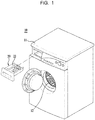
- FIG. 1 is a perspective view illustrating a conventional washing machine and a detergent dispenser thereof.
- a conventional washing machine 10 includes a cabinet 11 forming the external appearance of the washing machine 10, a tub (not shown) provided within the cabinet 11 and storing wash water, and a drum 12 rotatably provided within the tub and receiving and washing laundry.
- the washing machine 10 includes a detergent dispenser 20 into which detergents are input into improve washing effects of laundry washed by the drum 12.
- the detergent dispenser 20 includes a drawer-type detergent container 21 partially withdrawn forwards from the washing machine 10 and is configured such that detergents are input into the withdrawn detergent container 22 and then the detergent container 22 is inserted into the detergent dispenser 20 so as to wash laundry.
- the detergent dispenser 20 includes the detergent container 22 into which detergents are input, and the detergents, input into the detergent container 22, together with wash water are supplied to a space for washing, i.e., the tub or the drum 12.
- the detergent dispenser 20 in order to input a detergent to the above-described conventional detergent dispenser 20, the detergent dispenser 20 needs to be withdrawn in the forward direction of the washing machine 10. Therefore, in order to withdraw the detergent dispenser 20 in the forward direction of the washing machine 10, the detergent dispenser 20 needs to be formed on the front surface of the washing machine 10 and such a structure restricts the front design of the washing machine 10.
- WO2013/032224 A2 discloses a washing machine having a detergent dispenser positioned on an upper side of the cabinet.
- FR 2 512 854 A1 discloses an apparatus for the fanned-out supply of water from a pipe into a container, especially into a chamber of a detergent flush-in device for a washing machine.
- An object of the present invention is to provide a washing machine in which the position and structure of a detergent dispenser are improved so that a user may conveniently and easily input detergents to the detergent dispenser.
- Another object of the present invention is to provide a washing machine in which the position and structure of a detergent dispenser are improved so that limitations as to the design of the washing machine may be reduced.
- a washing machine includes a cabinet including an upper cover forming the rear portion of the upper surface of the cabinet, a tub provided within the cabinet, a drum rotatably provided within the tub, a detergent dispenser located above the front portion of the tub and exposed by the upper cover, and a dispenser cover opening and closing the upper surface of the detergent dispenser exposed by the upper cover and formed in front of the upper cover.
- the dispenser cover may form the front portion of the upper surface and form the front edge of the upper surface.
- the upper surface may include a single boundary line dividing the upper surface, the rear portion of the upper surface based on the single boundary line may be formed by the upper cover, and the front portion of the upper surface based on the single boundary line may be formed by the dispenser cover.
- the dispenser cover may be inserted into an area below the upper cover when the dispenser cover is opened.
- the dispenser cover may include a door bracket located above the detergent dispenser and a sliding door combined with the door bracket so as to be slidable and opening and closing the detergent dispenser according to sliding.
- the door bracket may include a body having a through hole to input the detergents to the detergent dispenser and guide parts formed at both sides of the body and having first and second guide slits guiding the sliding door, and first and second sliding protrusions inserted into the first and second guide slits may be formed at both sides of the sliding door.
- the first and second guide slits may be inclined downward in the moving direction of the sliding door.
- the gradient of the second guide slits may be greater than the gradient of the first guide slits.
- a depression part may be formed at the front portion of the upper surface of the upper cover and a depression part extending to the depression part of the upper cover may be formed at the rear portion of the upper surface of the sliding door.
- the front edge of the sliding door may form the front edge of the cabinet, and a connection surface connecting the upper surface of the sliding door and a front cover of the cabinet may be formed.
- connection surface may be formed as one selected from a curved surface and a flat surface.
- the dispenser cover may be hinged to the upper cover adjacent thereto and rotated to open the detergent dispenser.
- the dispenser cover may include rotatable hinges, each of which is provided with one side hinged to the front portion of the upper cover and a rotatable door hinged to the other sides of the rotatable hinges.
- the upper surfaces of the rotatable hinges and the upper surface of the upper cover may be coplanar when the detergent dispenser is closed, and the upper surfaces of the rotatable hinges may contact the upper surface of the upper cover when the detergent dispenser is opened.
- the rotatable hinge may have an annular cross-section with a designated opened part, one side of the rotatable hinge may be hinged to the rotatable door, and the other side of the rotatable hinge may be hinged to the upper cover.
- a depression part may be formed on the upper surface of the upper cover, and a protruding part supporting the rotatable door when the rotatable door is opened may be formed at a designated portion of the depression part.
- the front edge of the rotatable door may form the front edge of the cabinet, and a connection surface connecting the upper surface of the rotatable door and a front cover of the cabinet may be formed.
- connection surface may be formed as one selected from a curved surface and a flat surface.
- the washing machine may further include an air supply device including an intake part located at one side of the rear portion of the circumferential surface of the tub, an exhaust part located at the center of the front portion of the tub, and a duct connecting the intake part and the exhaust part and extending from one side of the rear portion of the tub to the center of the tub to guide air.
- an air supply device including an intake part located at one side of the rear portion of the circumferential surface of the tub, an exhaust part located at the center of the front portion of the tub, and a duct connecting the intake part and the exhaust part and extending from one side of the rear portion of the tub to the center of the tub to guide air.
- the detergent dispenser may be located above the front portion of the tub and extends so as to have detergent input holes at one side and the other side of the duct.
- the position and structure of a detergent dispenser are improved so that a user may conveniently and easily input detergents to the detergent dispenser.
- the position and structure of the detergent dispenser are improved so that limitations as to the design of the washing machine may be reduced.
- the present invention relates to a washing machine, as described above, and more particularly, to a detergent dispenser.
- the configuration of the washing machine except for the detergent dispenser may be the same as that of a general washing machine and does not limit the cope of the present invention. Therefore, a detailed description of the configuration of the general washing machine will be omitted and the detergent dispenser will be described in detail.
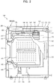
- FIG. 2 is a cross-sectional view illustrating the washing machine in accordance with the embodiment of the present invention
- FIG. 3 is a perspective view illustrating the washing machine in accordance with the embodiment of the present invention.
- a washing machine 100 in accordance with one embodiment of the present invention includes a cabinet 110 including an upper cover 112, a front cover 117, side covers 118, and a rear cover (not shown) forming the external appearance of the washing machine 100, a tub 130 provided within the cabinet 110 and storing wash water, a drum 140 rotatably mounted within the tub 130, an air supply device 160 heating and circulating air within the tub 130, a detergent dispenser 300 located at the front portion of a region above the tub 130 and exposed from the front cover 112 so that detergents may be input into the detergent dispenser 300, and a dispenser cover 200 or 400 forming a surface extending to the upper cover 112 and covering the detergent dispenser 300.
- the detergent dispenser 300 is mounted at the upper portion of the cabinet 110 so as to be exposed to the outside according to opening and closing of a part of the upper portion of the cabinet 110.
- the upper portion of the cabinet 110 is formed by the upper cover 112 forming a part of the upper surface of the cabinet 110 and the dispenser cover 200 or 400 shielding and exposing the detergent dispenser 300.
- the dispenser cover 200 or 400 forms the upper surface of the cabinet 110 and the front edge of the upper surface of the cabinet 110, simultaneosuly.
- the detergent dispenser 300 and the dispenser cover 200 or 400 will be described in detail later after description of the washing machine 100.
- the door 111 opening and closing the inside of the cabinet 110 is mounted at the front portion of the cabinet 110 and a control panel 120 to input a specific course performing operations, such as washing to drying, is installed at the upper portion of the front surface of the cabinet 110.
- the control panel 120 includes an operation unit (not shown) allowing a user to select one of washing to drying operations and a display unit (not shown) displaying the operation selected by the user and the operating process of the washing machine 100.
- a depression surface 113 is formed at the inner portion of the upper cover 112.
- a pair of side panels 114 to cover spaces between the upper cover 112 and both side covers 118 is formed at both sides of the upper cover 112.
- the tub 130 is provided within the cabinet 110 so as to store wash water, and a motor 150 to rotate the drum 140 is mounted at the rear portion of the tub 130. Further, springs (not shown) and a damper 131 supporting the tub 130 so as to absorb impact applied to the tub 130 are provided between the tub 130 and the cabinet 110.
- a water supply unit 132 including water supply valves 134 and water supply hoses 133 to supply wash water to the tub 130 and a drain unit 136 including a drain pump 138 and a drain hose 137 to drain wash water in the tub 130 after washing of laundry are provided on the tub 130.
- water supply valves 134 of the water supply unit 132 water supply valves 134 to control supply of hot water and cold water may be respectively provided.
- a hot water supply line 135d is connected to the water supply valve 134 to supply hot water.
- a 3-way valve to selectively supply cold water may be used as the water supply valve 134 to supply cold water.
- first and second water supply lines 135a and 135b and a preliminary water supply line 135c are connected to the 3-way valve 134 to supply cold water.
- first and second water supply lines 135a and 135b, preliminary water supply line 135c, and hot water supply line 135d are connected to the detergent dispenser 300, and may supply water directly to the tub 130 through the detergent dispenser 300 or mix supplied wash water with a liquid/powder detergent, a preliminary detergent, a bleaching agent and a fabric softener and supply the liquid/powder detergent, preliminary detergent, bleaching agent and fabric softener mixed with wash water to the tub 130.
- the functions of the first and second water supply lines 135a and 135b, the preliminary water supply line 135c, and the hot water supply line 135d will be described in detail in conjunction with description of the detergent dispenser 300.
- the drum 140 is rotatably provided within the tub 130, and laundry input through the door 111 is loaded in the drum 140.
- a plurality of dehydration holes 141 through which wash water passes are formed on the drum 140 and lifts 142 supporting the laundry in the drum 140 and thus tumbling the laundry when the drum 140 is rotated are formed on the inner surface of the drum 140. Washing performance may be improved according to movement of laundry by the lifters 142.
- the air supply device 160 heats air in the tub 130 and circulates the heated air in the tub 130, thus drying laundry located in the drum 140.
- the air supply device 160 includes an intake part 162 through which air in the tub 130 is introduced into the air supply device 160, an air blower fan 163 located above the intake part 162 and sucking in the air, a heater 164 heating the air sucked in by the air blower fan 163, and an exhaust part 165 supplying the air heated by the heater 164 to the inside of the drum 140.
- the intake part 162 is located on the outer circumferential surface of one side of the rear portion of the tub 130 so that air in the tub 130 is introduced directly into the intake part 162, and the exhaust part 165 is connected to the center of the front portion of the tub 130 so that air is exhausted directly to the inside of the drum 140.
- a duct 161 forming a movement path of air is provided between the intake part 162 and the exhaust part 165, and the heater 164 and the air blower fan 163 may be located within the duct 161.
- the duct 161 is connected from the intake part 162 to the exhaust part 165 and has a shape extending from one side of the rear portion of the tub 130 to the center of the front portion of the tub 130.
- air exhausted from the air blower fan 163 may be heated by the heater 164.
- the air supply device 130 of the present invention may have a structure in which air is directly sucked in through the outer circumferential surface of the tub 130 and heated and the heated air is supplied to the front portion of the tub 130, and humid air after drying of laundry may be condensed on the inner surface of the tub 130 due to a temperature difference between the inside of the tub 130 and the outside of the tub 130 and be converted into dry air. Otherwise, in order to convert humid air after drying of laundry into dry air, a part of humid air within the tub 130 may be discharged to the outside of the tub 130 and a part of dry air at the outside of the tub 130 may be introduced into the tub 130.
- a conventional tub, drum, and air supply device may be used or an improved tub, drum, and air supply device may be used.
- wash water is introduced into the tub 130 through the water supply unit 132 and washing, rinsing, and dehydrating are performed by rotation of the drum 140.
- wash water is discharged to the outside of the tub 130 through the drain unit 136.
- dehydrating of laundry is carried out. Thereby, a washing process is completed.
- air in the tub 130 is circulated by the air blower fan 163 of the air supply device 160 and the heater 164 of the air supply device 160 heats the air.
- the heated air is circulated in the tub 130 and the air supply device 160 and thus dries laundry loaded in the drum 140.
- air having dried the laundry is condensed on the inner circumferential surface of the tub 130 due to a temperature difference between the inside and the outside of the tub 130 and is drained to the outside of the tub 130 by the drain unit 136.
- Detergents to wash laundry need to be input into the washing machine 100 prior to or during operation of the above-described washing machine 100 and, in order to input detergents, the dispenser cover 200 or 400 provided at the upper portion of the washing machine 100 is opened so that a liquid detergent, a powder detergent, a fabric softener, a subsidiary detergent, etc. are selectively input into the detergent dispenser 300.
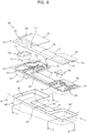
- FIG. 4 is an exploded perspective view illustrating the upper structure of the washing machine in accordance with the embodiment of the present invention
- FIG. 5 is a plan view illustrating the inner structure of the washing machine in accordance with the embodiment of the present invention.
- the detergent dispenser 300 is located on the upper surface of the front region of the tub 130 within the cabinet 110 and exposed to the outside according to opening of the dispenser cover 200.
- the detergent dispenser 300 is installed at the upper portion of the cabinet 110 and includes a lid unit 310, a flow path unit 320, and a collector unit 360.
- the detergent dispenser 300 has a plurality of input holes 312, 313, and 317 to input a liquid/powder detergent, a preliminary detergent, a fabric softener, a subsidiary detergent, etc.
- the detergent dispenser 300 includes a detergent supply hose (not shown) connected to the tub 130 so that the liquid/powder detergent, the preliminary detergent, the fabric softener, the subsidiary detergent, etc., which are selectively input, are mixed with separately supplied wash water and then supplied to the tub 130.
- a detergent supply hose (not shown) connected to the tub 130 so that the liquid/powder detergent, the preliminary detergent, the fabric softener, the subsidiary detergent, etc., which are selectively input, are mixed with separately supplied wash water and then supplied to the tub 130.
- the exhaust part 165 of the above-described air supply device 160 is located above the front portion of the tub 130 and the duct 161 of the air supply device 160 has a shape extending from one side of the rear portion of the tub 130 to the exhaust part 165.
- no input hole is formed at the central portion of the detergent dispenser 300 (more particularly, the portion of the detergent dispenser 300 above the exhaust part 165 of the air supply device 160) and duct space parts 315, in which the front end of the duct 161 and the discharge part 165 of the air supply device 160 are located, are formed at the central portion of the detergent dispenser 300.
- the duct space parts 315 in which the front end of the duct 161 and the discharge part 165 of the air supply device 160 are located, are formed at the central portion of the detergent dispenser 300, and the input holes 312, 313, and 317 to input a liquid/powder detergent, a preliminary detergent, a fabric softener, a subsidiary detergent, etc. are separately located at one side and the other side of the detergent dispenser 300.
- the input holes 312 and 313 to input a liquid/powder detergent and a preliminary detergent may be located at one side of the detergent dispenser 300 and the input hole 317 to input a fabric softener and a subsidiary detergent is located at the other side of the detergent dispenser 300.
- both sides of the detergent dispenser 300 may be formed integrally for convenience of installation and configured such that wash water supplied from one side (or the other side) of the detergent dispenser 300 may be supplied to the other side (or one side) of the detergent dispenser 300.
- the detergent dispenser 300 will be described in detail after description of the washing machine 100.
- the dispenser cover 200 or 400 is provided at the front portion of the upper surface of the washing machine (more particularly, above the detergent dispenser 300) so as to open and close the front portion of the upper surface of the washing machine 100.
- the dispenser cover 200 or 400 and the upper cover 112 may form the upper surface of the washing machine 100 and have the same extending surface, thus forming unification. That is, the dispenser cover 200 or 400 adjacent to the upper cover 112 forms an extension surface extending to the upper surface of the upper cover 112.
- the dispenser cover 200 or 400 forms the front portion of the upper surface of the washing machine 100 and extends to the front cover 117 of the washing machine 100. That is, since the dispenser cover 200 or 400 not only forms a part of the upper surface of the washing machine 100 but also has a connection surface 212 extending to the front cover 117 of the washing machine 100, the upper and front surfaces of the washing machine 100 are smoothly connected by the connection surface 212.
- the side panels 114 located at both sides of the upper cover 112 extend from both sides of the upper cover 112 to the dispenser cover 200 and thus finish both sides of the upper cover 112 and the dispenser cover 299.
- the structure of the dispenser cover 200 or 400 will be described in detail after description of the detergent dispenser 300.
- FIG. 6 is an exploded perspective view illustrating the detergent dispenser of the washing machine in accordance with the embodiment of the present invention
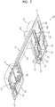
- FIG. 7 is a perspective view illustrating a flow path unit of the detergent dispenser in accordance with the embodiment of the present invention
- FIG. 8 is a plan view illustrating flow path connection of the detergent dispenser in accordance with the embodiment of the present invention.
- a detergent dispenser 300 in accordance with one embodiment of the present invention includes a lid unit 310, a flow path unit 320, and a collector unit 360, which are combined so as to overlap, as described above, and the lid unit 310, the flow path unit 320, and the collector unit 360 are individually manufactured and then combined integrally by thermal fusion.
- the lid unit 310 includes a detergent lid part 311, a connection lid part 314, and a subsidiary detergent lid part 316
- the flow path unit 320 includes a detergent part 321, a connection part 334, and a subsidiary detergent part 336
- the collector unit 360 includes a detergent collector part 361, an inclined flow path 364, and a subsidiary detergent collector part 367.
- the duct space part 315 into which the duct 161 and the exhaust part 165 of the air supply device 160 are inserted is formed at the center of the rear portion of each of the lid unit 310, the flow path unit 320, and the collector unit 360.
- the duct space parts 315 are commonly formed at the lid unit 310, the flow path unit 320, and the collector unit 360 and serve as a criterion to divide the lid unit 310, the flow path unit 320, and the collector unit 360. Therefore, the duct space parts 315 formed at the lid unit 310, the flow path unit 320, and the collector unit 360 are denoted by the same reference numeral.
- the detergent dispenser 300 is divided by the duct space parts 315, input positions of a liquid/powder detergent, a preliminary detergent, a bleaching agent, a fabric softener, etc. may be divisionally disposed at one side and the other side of the detergent dispenser 300 divided by the duct space parts 315.
- a detergent input hole 312 and a detergent input box 325 into which a liquid/powder detergent is input and a preliminary detergent input hole 313 and a preliminary detergent input box 329 into which an additional preliminary detergent is input may be located at one side of the detergent dispenser 300, and a subsidiary detergent input hole 317, a fabric softener input box 342 and a bleaching agent input box 339 may be located at the other side of the detergent dispenser 300.
- a user may clearly divide input positions of a detergent and a subsidiary detergent and user convenience may be increased.
- the lid unit 310 is combined with the upper portion of the flow path unit 320 and forms the upper portions of flow paths formed in the flow path unit 320.
- the lid unit 310 includes the detergent lid part 311 covering the upper portion of the detergent part 321 of the flow path unit 320, the connection lid part 314 covering the upper portion of the connection part 334 of the flow path unit 320, and the subsidiary detergent lid part 316 covering the subsidiary detergent part 336 of the flow path unit 320.
- the detergent lid part 311, the connection lid part 314, and the subsidiary detergent lid part 316 of the lid unit 310 may be formed separately, they may also be formed integrally.
- the above-described duct space part 315 is formed between the detergent lid part 311 and the subsidiary detergent lid part 316, and the detergent lid part 311 and the subsidiary detergent lid part 316 are connected by the connection lid part 314.
- the detergent input hole 312 into which a detergent is input and the preliminary detergent input hole 313 into which an additional preliminary detergent is input are formed on the detergent lid part 311. Further, the subsidiary detergent input hole 317 into which a bleaching agent and a fabric softener are input is formed on the subsidiary detergent lid part 316.
- Coupling parts 318 to fix the detergent dispenser 300 to the cabinet 110 after combination of the lid unit 310, the flow channel unit 320, and the collector unit 360 are formed at the outer surfaces of the detergent lid part 311 and the subsidiary detergent lid part 316.
- the flow path unit 320 includes, as exemplarily shown in FIGs. 6 and 7 , the detergent part 321 mixing input detergent and preliminary detergent with supplied wash water and supplying the detergent and preliminary detergent mixed wash water, the connection part 334 guiding a part of wash water supplied to the detergent part 321 to the subsidiary detergent part 336, and the subsidiary detergent part 336 mixing an input bleaching agent or fabric softener with wash water supplied through the connection part 334 and supplying the bleaching agent or fabric softener mixed with wash water.
- the detergent input box 325 into which a liquid detergent or a powder detergent is input and the preliminary detergent input box 329 into which a preliminary detergent is input are formed at the detergent part 321.
- the lower portions of the detergent input box 325 and the preliminary detergent input box 329 are inclined downward toward the rear portion of the flow path unit 320 and the rear portions of the detergent input box 325 and the preliminary detergent input box 329 are opened so that the input detergents together with wash water may move to the detergent collector part 361 of the collector unit 360.
- a first circulation flow path 328 is formed on the outer circumferential surface of the upper portion of the detergent input box 325 so that supplied wash water may be uniformly introduced into the detergent input box 325, and a plurality of overflow projections 328a through which wash water passing through the first circulation flow path 328 may overflow the outer circumferential surface of the detergent input box 325 are formed on the inner circumferential surface of the first circulation flow path 328.
- the overflow projections 328a may be formed at different heights in the movement direction of wash water moving along the first circulation flow path 328.
- a second circulation flow path 332 is formed on the outer circumferential surface of the upper portion of the preliminary detergent input box 329 so that supplied wash water may be uniformly introduced into the preliminary detergent input box 329, and a plurality of overflow projections 332a through which wash water passing through the second circulation flow path 332 may overflow the outer circumferential surface of the preliminary detergent input box 329 are formed on the inner circumferential surface of the second circulation flow path 332.
- the overflow projections 332a may be formed at different heights in the movement direction of wash water moving along the second circulation flow path 332.
- a plurality of connection parts 322, 323, and 324 to supply wash water to the detergent input box 325, the preliminary detergent input box 329, and the fabric softener input box 342 is provided at the rear portion of the detergent part 321.
- a hot water flow path 326 connected to one side of the first circulation flow path 328 and forming a flow path of hot water supplied from the hot water supply line 135d is formed at the hot water supply line connection part 322. Hot water supplied through the hot water supply line 135d is supplied to the first circulation flow path 328 through the hot water supply line connection part 322 and the hot water flow path 326 and supplied to the detergent input box 325 through the overflow projections 328a formed on the first circulation flow path 328 (with reference to FIG. 10 ).
- the first water supply flow path 327 and the preliminary water supply flow path 331 are formed so as to intersect at a designated angle, and a subsidiary detergent part water supply flow path 333 guiding wash water to the fabric softener input box 342 is formed in a central direction between the water supply directions of the first water supply flow path 327 and the preliminary water supply flow path 331 at the intersection between the first water supply flow path 327 and the preliminary water supply flow path 331.
- Wash water supplied through the first water supply line 135a is supplied to the other side of the first circulation flow path 328 through the first water supply line connection part 323 and the first water supply flow path 327 and supplied to the detergent input box 325 through the overflow projections 328a formed on the first circulation flow path 328 (with reference to FIG. 10 ).
- hot water supplied from the hot water supply line 135d and wash water supplied from the first wash water supply line 135a may be simultaneously or selectively supplied to the first circulation flow path 328 of the detergent input box 325 through the hot water supply flow path 135d and the first water supply flow path 327.
- Wash water supplied through the preliminary water supply flow path 331 is supplied to the preliminary detergent input box 329 through the preliminary water supply line connection part 324 and the preliminary water supply flow path 331 and supplied to the preliminary detergent input box 329 through the overflow projections 332a formed on the second circulation flow path 332 (with reference to FIG. 10 ).
- the subsidiary detergent part water supply flow path 333 is connected to the subsidiary detergent part 336 through the connection flow path 335 formed at the connection part 334.
- the fabric softener input box 342 into which a fabric softener is input and the bleaching agent input box 339 into which a bleaching agent is input are formed at the subsidiary detergent part 336.
- Overflow holes 341 which the fabric softener, the bleaching agent, and wash water input into the fabric softener input box 342 and the bleaching agent input box 339 overflow are formed at the upper portions of the fabric softener input box 342 and the bleaching agent input box 339
- siphons 344 to supply the fabric softener and the bleaching agent supplied to the fabric softener input box 342 and the bleaching agent input box 339 are formed at the lower portions of the fabric softener input box 342 and the bleaching agent input box 339.
- the siphons 344 are well known in the art and a detailed description thereof will thus be omitted.
- connection flow path 335 formed at the connection part 334 extends to the fabric softener input box 342, and wash water supplied form the preliminary water supply line 135c is supplied to the fabric softener input box 342 through the preliminary water supply line connection part 324, the preliminary water supply flow path 331, and the connection flow path 335 of the connection part 334 (with reference to FIG. 9 ).
- a second water supply line connection part 337 to which the second water supply line 135b is connected is provided at the rear portion of the bleaching agent input box 339, and a second water supply flow path 338 guiding wash water to the bleaching agent input box 339 is formed at the second water supply line connection part 337.
- wash water supplied from the second water supply line 135b is supplied to the bleaching agent input box 339 through the second water supply line connection part 337 and the second water supply flow path 338 (with reference to FIG. 10 ).
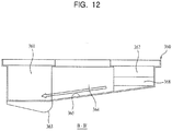
- the collector unit 360 is located under the flow path unit 320 and serves to supply various detergents and subsidiary detergents input into the detergent input box 325, the preliminary detergent input box 329, the fabric softener input box 342, and the bleaching agent input box 339 of the flow path unit 320 together with supplied wash water to the tub 130.
- the collector unit 360 includes the detergent collector part 361 provided with a discharge hole 363 through which the collected detergent and wash water are discharged to the tub 130, the subsidiary detergent collector part 367 in which the fabric softener and the bleaching agent are collected, and the inclined flow path 364 connecting the detergent collector part 361 and the subsidiary detergent collector part 367.
- the detergent collector part 361, the subsidiary detergent collector part 367, and the inclined flow path 364 are formed integrally.
- the above-described duct space part 315 is formed between the detergent collector part 361 and the subsidiary detergent collector part 367, and the detergent collector part 361 and the subsidiary detergent collector part 367 are connected by the inclined flow path 364.
- the lower surfaces of the detergent collector part 361, the subsidiary detergent collector part 367, and the inclined flow path 364 are inclined so that detergents and wash water collected in the detergent collector part 361, the subsidiary detergent collector part 367, and the inclined flow path 364 may be supplied to the tub 130 through the discharge hole 363 provided on the detergent collector part 361.
- a first inclined surface 368 which is inclined downward toward the inclined flow path 364 connected to one side of the subsidiary detergent collector part 367 is formed on the lower surface of the subsidiary detergent collector part 367
- a second inclined surface 365 which is inclined downward from the first inclined surface 368 of the subsidiary detergent collector part 367 toward the detergent collector part 361 is formed on the lower surface of the inclined flow path 364.
- a third inclined surface 362 which is inclined downward from the second inclined surface 365 of the inclined flow path 364 toward the discharge hole 363 is formed on the lower surface of the detergent collector part 361.
- detergents input into the detergent collector part 351 are discharged along the third inclined surface 362 of the detergent collector part 351 through the discharge hole 363 and input into the tub 130, and a fabric softener and a bleaching agent input into the subsidiary detergent collector part 367 are introduced to the inclined flow path 364 along the first inclined surface 368 of the subsidiary detergent collector part 367 and the fabric softener and the bleaching agent introduced to the inclined flow path 364 are introduced to the detergent collector part 361 along the second inclined surface 365 of the inclined flow path 364, discharged along the third inclined surface 362 of the detergent collector part 351 through the discharge hole 363, and input into the tub 13.
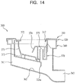
- the detergent dispenser 300 in accordance with the present invention includes a liquid detergent input guide 370 to input a liquid detergent. That is, in case of the detergent dispenser 300 including the lid unit 310, the flow path unit 320, and the collector unit 360, if a liquid detergent is input directly to the detergent input box 325, the liquid detergent together with wash water is supplied directly to the tub 130 and may thus be supplied at an undesired time. Therefore, the liquid detergent input guide 370 to supply the liquid detergent using siphonage is required so as to adjust input of the liquid detergent.
- FIG. 14 is a cross-sectional view illustrating the installed structure of the liquid detergent input guide 370 in the detergent dispenser 300.
- the liquid detergent input guide 370 includes a liquid detergent reservoir 371 separably mounted in the detergent input box 325 of the flow path unit 320 and storing a liquid detergent, and a liquid detergent siphon 375 supplying the liquid detergent stored in the liquid detergent reservoir 371 using siphonage is provided on the inner surface of the liquid detergent reservoir 371.
- a handle 372 to attach or detach the liquid detergent input guide 370 to or from the detergent dispenser 300 is provided at one side of the liquid detergent reservoir 371, and an input boundary protrusion 374 restricting the input amount of the liquid detergent is provided at one side of the liquid detergent siphon 375.
- a plurality of support protrusions 373 supporting the liquid detergent input guide 370 when the liquid detergent input guide 370 is mounted in the detergent input box 325 is provided on the lower surface of the liquid detergent input guide 370.
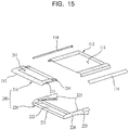
- FIG. 15 is an exploded perspective view of an upper panel and a dispenser cover of a washing machine in accordance with one embodiment of the present invention
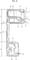
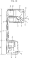
- FIG. 16 is a partial cross-sectional view of the dispenser cover in accordance with the embodiment of the present invention.
- the dispenser cover 200 in accordance the embodiment of the present invention includes a door bracket 220 installed above the detergent dispenser 300 installed within the washing machine 100 and a sliding door 210, the moving path of which is guided by the door bracket 220 so that, when the sliding door 210 is opened, the sliding door 210 moves to an area below the upper cover 112 to open the detergent dispenser 300.
- the detergent dispenser 300 and the upper cover 112 are separated from each other by a designated interval so as to move the sliding door 210 of the dispenser cover 200.
- the sliding door 210 is located on the upper surface of the front portion of the washing machine 100, i.e., the front portion of the upper cover 112, so as to be exposed. Further, the outer surface of the sliding door 210 extends to the upper surface of the upper cover 112. That is, the depression surface 113 to increase strength of the upper cover 112 is formed on the upper surface of the upper cover 112, and a depression surface 211 extending to the depression surface 112 of the upper cover 112 is formed on the upper surface of the sliding door 210. Therefore, the upper surface of the washing machine 100 has one depressed shape formed by the depression surface 113 of the upper cover 112 and the depression surface 211 of the sliding door 210.
- connection surface 212 extending along the outer shape of the front cover 117 of the cabinet 110 is formed at the front edge of the sliding door 210. That is, the front edge of the sliding door 210 forms the upper edge of the front surface of the washing machine 100.
- connection surface 212 formed as a designated curved surface may be formed at the front edge of the sliding door 210, and the upper surface of the sliding door 210 and the front surface of the front cover 117 are smoothly connected by the curved connection surface 212.
- connection surface 212 of the sliding door 210 may be formed as an inclined surface having a designated angle. If the front edge of the sliding door 210 is formed as an inclined surface, the front edge of the washing machine 100 may be formed by three flat surfaces or curved surfaces including the sliding door 210, the connection surface 212, and the front cover 117.
- the first and second sliding protrusions 213 and 214 are separated by a designated interval, and the second sliding protrusions 214 are formed in the rear of the first sliding protrusions 213.
- the door bracket 220 includes a body 221 located above the detergent dispenser 300 and guide parts 223 located at both side ends of the body 221 and guiding the sliding door 220 so as to be slidable.
- a pair of guide parts 223 is formed in a shape perpendicular to both ends of the body 221 and extends to a designated length toward an area below the upper cover 112.
- first and second guide slits 224 and 224 are symmetrically formed on the opposite inner surfaces of the guide parts 223 in a pair.
- the first guide slits 224 are located in front of the second guide slits 225.
- the first guide slits 224 and the second guide slits 225 have different gradients, and the first and second guide slits 224 and 225 are inclined downward as they move toward the upper cover 112.
- the second guide slits 225 may be a greater gradient than the first guide slits 224.
- the first sliding protrusions 213 are inserted into the first guide slits 224 and the second sliding protrusions 214 are inserted into the second guide slits 225. Therefore, when the sliding door 210 slides, the first and second sliding protrusions 213 and 214 are moved along the first and second guide slits 224 and 225.
- the first guide slits 224 and the second guide slits 225 are formed with different gradients, and the upper ends of the first and second guide slits 224 and 225 extend to a position where the sliding door 210 closes the detergent dispenser 300 when the first and second sliding protrusions 213 and 214 combined with the first and second guide slits 224 and 225 are located at the upper ends of the first and second guide slits 224 and 225.
- the lower ends of the first and second guide slits 224 and 225 extend to a position where the sliding door 210 opens the detergent dispenser 300 and is moved to an area below the upper cover 112 when the first and second sliding protrusions 213 and 214 combined with the first and second guide slits 224 and 225 are located at the lower ends of the first and second guide slits 224 and 225.
- the disperser cover 200 closes the detergent dispenser 300. That is, the sliding door 210 of the dispenser cover 200 is withdrawn from the area below the upper cover 112 and is located on the upper surface of the detergent dispenser 300 (with reference to FIG. 17 ).
- first and second sliding protrusions 213 and 214 formed at both sides of the sliding door 210 are located at the upper ends of the first and second guide slits 224 and 225 formed on the guide parts 223 of the door bracket 220 and the front edge of the sliding door 210 forms the upper edge of the front surface of the washing machine 100.
- the first and second sliding protrusions 213 and 214 of the sliding door 210 are moved along the first and second guide slits 224 and 225 formed on the guide parts 223 of the door bracket 220 and thus, the sliding door 210 is moved.
- first and second guide slits 224 and 225 are inclined downward as they move toward the upper cover 112, the sliding door 210 is moved and inserted into the area below the upper cover 112 and thus opens the detergent dispenser 300 (with reference to FIG. 18 ).
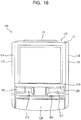
- FIG. 19 is a perspective view illustrating a washing machine to which the dispenser cover in accordance with this embodiment of the present invention is applied.
- a detergent dispenser 300 to input detergents is installed at the upper region of the front portion of the inside of the washing machine 100, the rear portion of the upper surface of the washing machine 100 is formed by an upper cover 112, and the dispenser cover 400 rotated to the outside of the washing machine 100 to open and close the detergent dispenser 300 is provided at the front portion of the upper surface of the washing machine 100 (particularly, an area above the detergent dispenser 300).
- the upper cover 112 and the dispenser cover 400 form the upper surface of the washing machine 100 have the same extension surface, thus forming unification. That is, the dispenser cover 400 adjacent to the upper cover 112 forms an extension surface extending to the upper surface of the upper cover 112 when the detergent dispenser 300 is closed. Further, side panels 114 located at both sides of the upper cover 112 extend in the direction of the dispenser cover 400 and thus finish both sides of the upper cover 112 and the dispenser cover 400.
- the dispenser cover 400 forms the front portion of the upper surface of the washing machine 100 and extends so as to be continued to the front cover 117 of the washing machine, simultaneously. That is, the dispenser cover 400 forms a part of the upper surface of the washing machine 100 and the upper surface and the front surface of the washing machine 100 are smoothly connected by a connection surface 311 extending to the front cover 117 of the washing machine 100.
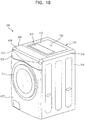
- FIG. 20 is a perspective view illustrating an opened state of the dispenser cover in accordance with the embodiment of the present invention
- FIG. 21 is a partial cross-sectional view illustrating the dispenser cover in accordance with the embodiment of the present invention
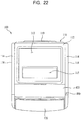
- FIGs. 22 and 23 are plan views illustrating operation of the dispenser cover in accordance with the embodiment of the present invention.
- the dispenser cover 400 in accordance with this embodiment of the present invention includes rotatable hinges 420 rotatably provided at the front portion of the upper cover 112 of the washing machine 100 and a rotatable door 410 rotated to the outside of the washing machine 100 to open the detergent dispenser 300.
- the rotatable door 410 is located on the upper surface of the front portion of the washing machine 100, i.e., the front portion of the upper cover 112, so as to be exposed. Further, the outer surface of the sliding door 410 extends to the upper surface of the upper cover 112. A depression surface 113 to increase strength of the upper cover 112 is formed on the upper surface of the upper cover 112, and a protruding part 115 to support the rotatable door 410 when the rotatable door 410 is opened is formed at a designated portion of the depression surface 113.
- connection surface 411 extending along the outer shape of the front cover 117 of the cabinet 110 is formed at the front edge of the rotatable door 410. That is, the front edge of the rotatable door 410 forms the upper edge of the front surface of the washing machine 100.
- connection surface 411 formed as a designated curved surface may be formed at the front edge of the rotatable door 410, and the upper surface of the rotatable door 410 and the front surface of the front cover 117 are smoothly connected by the curved connection surface 311.
- connection surface 411 of the rotatable door 410 may be formed as an inclined surface having a designated angle. If the front edge of the rotatable door 410 is formed as an inclined surface, the front edge of the washing machine 100 may be formed by three flat surfaces or curved surfaces including the rotatable door 410, the connection surface 411, and the front cover 117.
- a plurality of reinforcing ribs 412 to increase strength of the rotatable door 410 is formed on the inner surface of the rotatable door 410.
- the reinforcing ribs 412 may not only increase strength of the rotatable door 410 but also guide a detergent container in which detergents are stored when the detergents are input into the detergent dispenser 300.
- the reinforcing ribs 312 may be formed between input holes, such as a detergent input hole 312, a preliminary detergent input hole 313, and a subsidiary detergent input hole 317 formed on the detergent dispenser 300.
- the rotatable hinges 420 are rotatably combined with the rotatable door 410 and the upper cover 117, respectively.
- hinge parts 414 with which one side of each rotatable hinge 320 is rotatably combined are formed at the rear portion of the rotatable door 410, and hinge brackets 116 with which the other side of each rotatable hinge 320 is rotatably combined are provided on the lower surface of the front portion of the upper cover 112.
- the rotatable hinge 420 includes an annular body 421 having an arc-shaped cross-section, one side of which is opened, a door connection terminal 422 formed at one side of the annular body 421 so that the rotatable door 410 is connected to the door connection terminal 422, and an upper cover connection terminal 423 formed at the other side of the annular body 421 so that the upper cover 112 is rotatably connected to the upper cover connection terminal 423. Therefore, the rotatable door 410 is rotated about two rotary axes.
- the rotating state of the rotatable hinges 420 will be described.
- the rotatable door 410 and the hinge brackets 116 rotatably combined with the rotatable hinges 420 are rotated and the upper cover 112 and the rotatable door 410 form the same flat surface (with reference to FIG. 22 ).
- the rotatable door 410 and the hinge brackets 116 rotatably combined with the rotatable hinges 420 are rotated and the upper surface of the rotatable door 410 is attached to the protruding part 115 of the upper cover 112 and thus supported (with reference to FIG. 23 ).
- the detergent dispenser 300 is located on the upper surface of the washing machine 100 and the dispenser cover 200 or 400 opening and closing the detergent dispenser 300 is formed on the upper surface of the washing machine 100 and thus, a user may more easily and conveniently input detergents into the detergent dispenser 300.
- the detergent part 321 and the subsidiary detergent part 336 of the detergent dispenser 300 are divided and thus provide high visibility to a user in terms of input of detergents and subsidiary detergents.
- the upper cover 112 and the dispenser cover 200 or 400 forming the upper surface of the washing machine 100 are continuously formed and thus, the upper surface of the washing machine 100 may have 3D effects.
- the position and structure of a detergent dispenser are improved so that a user may conveniently and easily input detergents to the detergent dispenser.
- the position and structure of the detergent dispenser are improved so that limitations as to the design of the washing machine may be reduced.
Description
- The present invention relates to a washing machine, and more particularly, to a washing machine having a detergent dispenser provided on the upper surface thereof and a dispenser cover to open and close the detergent dispenser.
- In general, washing machines include dryers drying laundry and washers washing laundry. Among these washing machines, a washer uses detergents to wash laundry and thus generally includes a detergent dispenser to input detergents. Therefore, a detergent dispenser is essential in washers.
- Hereinafter, a conventional detergent dispenser will be described in brief with reference to the accompanying drawings.
-
FIG. 1 is a perspective view illustrating a conventional washing machine and a detergent dispenser thereof. - As exemplarily shown in
FIG. 1 , aconventional washing machine 10 includes acabinet 11 forming the external appearance of thewashing machine 10, a tub (not shown) provided within thecabinet 11 and storing wash water, and adrum 12 rotatably provided within the tub and receiving and washing laundry. Thewashing machine 10 includes adetergent dispenser 20 into which detergents are input into improve washing effects of laundry washed by thedrum 12. - The
detergent dispenser 20 includes a drawer-type detergent container 21 partially withdrawn forwards from thewashing machine 10 and is configured such that detergents are input into the withdrawndetergent container 22 and then thedetergent container 22 is inserted into thedetergent dispenser 20 so as to wash laundry. - That is, the
detergent dispenser 20 includes thedetergent container 22 into which detergents are input, and the detergents, input into thedetergent container 22, together with wash water are supplied to a space for washing, i.e., the tub or thedrum 12. - In case of the
detergent dispenser 20 of theconventional washing machine 10, when detergents are input into thedetergent dispenser 20, the withdrawn state of thedetergent dispenser 20 in the forward direction of thewashing machine 10 is maintained and a user inputs detergents to thedetergent dispenser 20. - However, since detergents need to be input into the above-described
conventional detergent dispenser 20 under the condition that thedetergent dispenser 20 is withdrawn from the front surface of thewashing machine 10, a user inputs a detergent to thedetergent dispenser 20 while holding a detergent container or inputs a detergent to thedetergent dispenser 20 under the condition that a discharge hole of the detergent container is held by thedetergent dispenser 20. - However, if a user inputs a detergent to the
detergent dispenser 20 while lifting a detergent container, the user must exert great force and may thus be inconvenienced. Further, if a user inputs a detergent to thedetergent dispenser 20 under the condition that the detergent container is held by thedetergent dispenser 20, thedetergent dispenser 20 may be damaged by load of the detergent container. - Further, in order to input a detergent to the above-described
conventional detergent dispenser 20, thedetergent dispenser 20 needs to be withdrawn in the forward direction of thewashing machine 10. Therefore, in order to withdraw thedetergent dispenser 20 in the forward direction of thewashing machine 10, thedetergent dispenser 20 needs to be formed on the front surface of thewashing machine 10 and such a structure restricts the front design of thewashing machine 10. -
WO2013/032224 A2 discloses a washing machine having a detergent dispenser positioned on an upper side of the cabinet. -
FR 2 512 854 A1 - An object of the present invention is to provide a washing machine in which the position and structure of a detergent dispenser are improved so that a user may conveniently and easily input detergents to the detergent dispenser.
- Another object of the present invention is to provide a washing machine in which the position and structure of a detergent dispenser are improved so that limitations as to the design of the washing machine may be reduced.
- In one embodiment of the present invention, a washing machine includes a cabinet including an upper cover forming the rear portion of the upper surface of the cabinet, a tub provided within the cabinet, a drum rotatably provided within the tub, a detergent dispenser located above the front portion of the tub and exposed by the upper cover, and a dispenser cover opening and closing the upper surface of the detergent dispenser exposed by the upper cover and formed in front of the upper cover.
- The dispenser cover may form the front portion of the upper surface and form the front edge of the upper surface.
- The upper surface may include a single boundary line dividing the upper surface, the rear portion of the upper surface based on the single boundary line may be formed by the upper cover, and the front portion of the upper surface based on the single boundary line may be formed by the dispenser cover.
- The dispenser cover may be inserted into an area below the upper cover when the dispenser cover is opened.
- The dispenser cover may include a door bracket located above the detergent dispenser and a sliding door combined with the door bracket so as to be slidable and opening and closing the detergent dispenser according to sliding.
- The door bracket may include a body having a through hole to input the detergents to the detergent dispenser and guide parts formed at both sides of the body and having first and second guide slits guiding the sliding door, and first and second sliding protrusions inserted into the first and second guide slits may be formed at both sides of the sliding door.
- The first and second guide slits may be inclined downward in the moving direction of the sliding door.
- The gradient of the second guide slits may be greater than the gradient of the first guide slits.
- A depression part may be formed at the front portion of the upper surface of the upper cover and a depression part extending to the depression part of the upper cover may be formed at the rear portion of the upper surface of the sliding door.
- The front edge of the sliding door may form the front edge of the cabinet, and a connection surface connecting the upper surface of the sliding door and a front cover of the cabinet may be formed.
- The connection surface may be formed as one selected from a curved surface and a flat surface.
- The dispenser cover may be hinged to the upper cover adjacent thereto and rotated to open the detergent dispenser.
- The dispenser cover may include rotatable hinges, each of which is provided with one side hinged to the front portion of the upper cover and a rotatable door hinged to the other sides of the rotatable hinges.
- The upper surfaces of the rotatable hinges and the upper surface of the upper cover may be coplanar when the detergent dispenser is closed, and the upper surfaces of the rotatable hinges may contact the upper surface of the upper cover when the detergent dispenser is opened.
- The rotatable hinge may have an annular cross-section with a designated opened part, one side of the rotatable hinge may be hinged to the rotatable door, and the other side of the rotatable hinge may be hinged to the upper cover.
- A depression part may be formed on the upper surface of the upper cover, and a protruding part supporting the rotatable door when the rotatable door is opened may be formed at a designated portion of the depression part.
- The front edge of the rotatable door may form the front edge of the cabinet, and a connection surface connecting the upper surface of the rotatable door and a front cover of the cabinet may be formed.
- The connection surface may be formed as one selected from a curved surface and a flat surface.
- The washing machine may further include an air supply device including an intake part located at one side of the rear portion of the circumferential surface of the tub, an exhaust part located at the center of the front portion of the tub, and a duct connecting the intake part and the exhaust part and extending from one side of the rear portion of the tub to the center of the tub to guide air.
- The detergent dispenser may be located above the front portion of the tub and extends so as to have detergent input holes at one side and the other side of the duct.
- In a washing machine in accordance with one embodiment of the present invention, the position and structure of a detergent dispenser are improved so that a user may conveniently and easily input detergents to the detergent dispenser.
- Further, in the washing machine in accordance with the embodiment of the present invention, the position and structure of the detergent dispenser are improved so that limitations as to the design of the washing machine may be reduced.
- The accompanying drawings, which are included to provide a further understanding of the invention and are incorporated in and constitute a part of this application, illustrate embodiment(s) of the invention and together with the description serve to explain the principle of the invention. In the drawings:
-
FIG. 1 is a perspective view illustrating a conventional washing machine; -
FIG. 2 is a cross-sectional view illustrating a washing machine in accordance with one embodiment of the present invention in brief; -
FIG. 3 is a perspective view illustrating the washing machine in accordance with the embodiment of the present invention; -
FIG. 4 is an exploded perspective view illustrating the upper structure of the washing machine in accordance with the embodiment of the present invention; -
FIG. 5 is a plan view illustrating the inner structure of the washing machine in accordance with the embodiment of the present invention; -
FIG. 6 is an exploded perspective view illustrating a detergent dispenser of a washing machine in accordance with one embodiment of the present invention; -
FIG. 7 is a perspective view illustrating a flow path unit of the detergent dispenser in accordance with the embodiment of the present invention; -
FIG. 8 is a plan view illustrating flow path connection of the detergent dispenser in accordance with the embodiment of the present invention; -
FIGs. 9 and10 are schematic views illustrating supply of wash water by the detergent dispenser in accordance with the embodiment of the present invention; -
FIGs. 11 to 13 are cross-sectional views illustrating a collector unit of the detergent dispenser in accordance with the embodiment of the present invention; -
FIG. 14 is a cross-sectional view illustrating the internal structure of the detergent dispenser in accordance with the embodiment of the present invention; -
FIG. 15 is an exploded perspective view illustrating an upper panel and a dispenser cover of a washing machine in accordance with one embodiment of the present invention; -
FIG. 16 is a partial cross-sectional view of the dispenser cover in accordance with the embodiment of the present invention; -
FIGs. 17 and18 are plan views illustrating operation of the dispenser cover in accordance with the embodiment of the present invention; -
FIG. 19 is a perspective view illustrating a washing machine to which a dispenser cover in accordance with another embodiment of the present invention is applied; -
FIG. 20 is a perspective view illustrating an opened state of the dispenser cover in accordance with the embodiment of the present invention; -
FIG. 21 is a partial cross-sectional view illustrating the dispenser cover in accordance with the embodiment of the present invention; and -
FIGs. 22 and23 are plan views illustrating operation of the dispenser cover in accordance with the embodiment of the present invention. - Reference will now be made in detail to the preferred embodiments of the present invention, examples of which are illustrated in the accompanying drawings.
- Terms of respective elements used in the following description are terms defined taking into consideration of the functions obtained in the present invention. Therefore, these terms do not limit technical elements in the present invention. Further, the defined terms of the respective elements will be called other terms in the art.
- Further, the present invention relates to a washing machine, as described above, and more particularly, to a detergent dispenser. The configuration of the washing machine except for the detergent dispenser may be the same as that of a general washing machine and does not limit the cope of the present invention. Therefore, a detailed description of the configuration of the general washing machine will be omitted and the detergent dispenser will be described in detail.
- First, with reference to
FIGs. 2 and3 , a washing machine in accordance with one embodiment of the present invention will be described in detail.FIG. 2 is a cross-sectional view illustrating the washing machine in accordance with the embodiment of the present invention andFIG. 3 is a perspective view illustrating the washing machine in accordance with the embodiment of the present invention. - As exemplarily shown in
FIGs. 2 and3 , awashing machine 100 in accordance with one embodiment of the present invention includes acabinet 110 including anupper cover 112, afront cover 117, side covers 118, and a rear cover (not shown) forming the external appearance of thewashing machine 100, atub 130 provided within thecabinet 110 and storing wash water, adrum 140 rotatably mounted within thetub 130, anair supply device 160 heating and circulating air within thetub 130, adetergent dispenser 300 located at the front portion of a region above thetub 130 and exposed from thefront cover 112 so that detergents may be input into thedetergent dispenser 300, and adispenser cover upper cover 112 and covering thedetergent dispenser 300. - The
detergent dispenser 300 is mounted at the upper portion of thecabinet 110 so as to be exposed to the outside according to opening and closing of a part of the upper portion of thecabinet 110. For this purpose, the upper portion of thecabinet 110 is formed by theupper cover 112 forming a part of the upper surface of thecabinet 110 and thedispenser cover detergent dispenser 300. Here, thedispenser cover cabinet 110 and the front edge of the upper surface of thecabinet 110, simultaneosuly. Thedetergent dispenser 300 and thedispenser cover washing machine 100. - Further, the
door 111 opening and closing the inside of thecabinet 110 is mounted at the front portion of thecabinet 110 and acontrol panel 120 to input a specific course performing operations, such as washing to drying, is installed at the upper portion of the front surface of thecabinet 110. Thecontrol panel 120 includes an operation unit (not shown) allowing a user to select one of washing to drying operations and a display unit (not shown) displaying the operation selected by the user and the operating process of thewashing machine 100. - Here, in order to increase strength of the
upper cover 112 of thecabinet 110, adepression surface 113 is formed at the inner portion of theupper cover 112. A pair ofside panels 114 to cover spaces between theupper cover 112 and both side covers 118 is formed at both sides of theupper cover 112. - The
tub 130 is provided within thecabinet 110 so as to store wash water, and a motor 150 to rotate thedrum 140 is mounted at the rear portion of thetub 130. Further, springs (not shown) and adamper 131 supporting thetub 130 so as to absorb impact applied to thetub 130 are provided between thetub 130 and thecabinet 110. - A
water supply unit 132 includingwater supply valves 134 andwater supply hoses 133 to supply wash water to thetub 130 and adrain unit 136 including a drain pump 138 and adrain hose 137 to drain wash water in thetub 130 after washing of laundry are provided on thetub 130. - As the
water supply valves 134 of thewater supply unit 132,water supply valves 134 to control supply of hot water and cold water may be respectively provided. A hotwater supply line 135d is connected to thewater supply valve 134 to supply hot water. Further, as thewater supply valve 134 to supply cold water, a 3-way valve to selectively supply cold water may be used. Here, first and secondwater supply lines water supply line 135c are connected to the 3-way valve 134 to supply cold water. - Further, all the above-described first and second
water supply lines water supply line 135c, and hotwater supply line 135d are connected to thedetergent dispenser 300, and may supply water directly to thetub 130 through thedetergent dispenser 300 or mix supplied wash water with a liquid/powder detergent, a preliminary detergent, a bleaching agent and a fabric softener and supply the liquid/powder detergent, preliminary detergent, bleaching agent and fabric softener mixed with wash water to thetub 130. The functions of the first and secondwater supply lines water supply line 135c, and the hotwater supply line 135d will be described in detail in conjunction with description of thedetergent dispenser 300. - The
drum 140 is rotatably provided within thetub 130, and laundry input through thedoor 111 is loaded in thedrum 140. A plurality of dehydration holes 141 through which wash water passes are formed on thedrum 140 and lifts 142 supporting the laundry in thedrum 140 and thus tumbling the laundry when thedrum 140 is rotated are formed on the inner surface of thedrum 140. Washing performance may be improved according to movement of laundry by thelifters 142. - The
air supply device 160 heats air in thetub 130 and circulates the heated air in thetub 130, thus drying laundry located in thedrum 140. Theair supply device 160 includes anintake part 162 through which air in thetub 130 is introduced into theair supply device 160, anair blower fan 163 located above theintake part 162 and sucking in the air, aheater 164 heating the air sucked in by theair blower fan 163, and anexhaust part 165 supplying the air heated by theheater 164 to the inside of thedrum 140. - Here, the
intake part 162 is located on the outer circumferential surface of one side of the rear portion of thetub 130 so that air in thetub 130 is introduced directly into theintake part 162, and theexhaust part 165 is connected to the center of the front portion of thetub 130 so that air is exhausted directly to the inside of thedrum 140. Aduct 161 forming a movement path of air is provided between theintake part 162 and theexhaust part 165, and theheater 164 and theair blower fan 163 may be located within theduct 161. Theduct 161 is connected from theintake part 162 to theexhaust part 165 and has a shape extending from one side of the rear portion of thetub 130 to the center of the front portion of thetub 130. - Further, in terms of flow of air, air exhausted from the
air blower fan 163 may be heated by theheater 164. Theair supply device 130 of the present invention may have a structure in which air is directly sucked in through the outer circumferential surface of thetub 130 and heated and the heated air is supplied to the front portion of thetub 130, and humid air after drying of laundry may be condensed on the inner surface of thetub 130 due to a temperature difference between the inside of thetub 130 and the outside of thetub 130 and be converted into dry air. Otherwise, in order to convert humid air after drying of laundry into dry air, a part of humid air within thetub 130 may be discharged to the outside of thetub 130 and a part of dry air at the outside of thetub 130 may be introduced into thetub 130. - Here, as the components, such as the
tub 130, thedrum 140, and theair supply device 160, a conventional tub, drum, and air supply device may be used or an improved tub, drum, and air supply device may be used. - Now, operation of the
washing machine 100 will be described in brief. Wash water is introduced into thetub 130 through thewater supply unit 132 and washing, rinsing, and dehydrating are performed by rotation of thedrum 140. During washing and rinsing, wash water is discharged to the outside of thetub 130 through thedrain unit 136. After washing and rinsing, dehydrating of laundry is carried out. Thereby, a washing process is completed. - Further, if drying is carried out, air in the
tub 130 is circulated by theair blower fan 163 of theair supply device 160 and theheater 164 of theair supply device 160 heats the air. The heated air is circulated in thetub 130 and theair supply device 160 and thus dries laundry loaded in thedrum 140. Here, air having dried the laundry is condensed on the inner circumferential surface of thetub 130 due to a temperature difference between the inside and the outside of thetub 130 and is drained to the outside of thetub 130 by thedrain unit 136. - Detergents to wash laundry need to be input into the
washing machine 100 prior to or during operation of the above-describedwashing machine 100 and, in order to input detergents, thedispenser cover washing machine 100 is opened so that a liquid detergent, a powder detergent, a fabric softener, a subsidiary detergent, etc. are selectively input into thedetergent dispenser 300. - Hereinafter, the installed state of the
detergent dispenser 300 in thewashing machine 100 in accordance with the embodiment of the present invention will be described in detail with reference to the accompanying drawings.FIG. 4 is an exploded perspective view illustrating the upper structure of the washing machine in accordance with the embodiment of the present invention andFIG. 5 is a plan view illustrating the inner structure of the washing machine in accordance with the embodiment of the present invention. - As exemplarily shown in
FIGs. 4 and5 , thedetergent dispenser 300 is located on the upper surface of the front region of thetub 130 within thecabinet 110 and exposed to the outside according to opening of thedispenser cover 200. - The
detergent dispenser 300 is installed at the upper portion of thecabinet 110 and includes alid unit 310, aflow path unit 320, and acollector unit 360. Thedetergent dispenser 300 has a plurality of input holes 312, 313, and 317 to input a liquid/powder detergent, a preliminary detergent, a fabric softener, a subsidiary detergent, etc. - Further, the
detergent dispenser 300 includes a detergent supply hose (not shown) connected to thetub 130 so that the liquid/powder detergent, the preliminary detergent, the fabric softener, the subsidiary detergent, etc., which are selectively input, are mixed with separately supplied wash water and then supplied to thetub 130. - The
exhaust part 165 of the above-describedair supply device 160 is located above the front portion of thetub 130 and theduct 161 of theair supply device 160 has a shape extending from one side of the rear portion of thetub 130 to theexhaust part 165. - Therefore, in order to avoid interference between the
detergent dispenser 300 and theexhaust part 165 or theduct 161 of theair supply device 100, no input hole is formed at the central portion of the detergent dispenser 300 (more particularly, the portion of thedetergent dispenser 300 above theexhaust part 165 of the air supply device 160) andduct space parts 315, in which the front end of theduct 161 and thedischarge part 165 of theair supply device 160 are located, are formed at the central portion of thedetergent dispenser 300. - That is, the
duct space parts 315, in which the front end of theduct 161 and thedischarge part 165 of theair supply device 160 are located, are formed at the central portion of thedetergent dispenser 300, and the input holes 312, 313, and 317 to input a liquid/powder detergent, a preliminary detergent, a fabric softener, a subsidiary detergent, etc. are separately located at one side and the other side of thedetergent dispenser 300. The input holes 312 and 313 to input a liquid/powder detergent and a preliminary detergent may be located at one side of thedetergent dispenser 300 and theinput hole 317 to input a fabric softener and a subsidiary detergent is located at the other side of thedetergent dispenser 300. - Further, although one side and the other side of the
detergent dispenser 300 may be installed so as to be separated from each other, both sides of thedetergent dispenser 300 may be formed integrally for convenience of installation and configured such that wash water supplied from one side (or the other side) of thedetergent dispenser 300 may be supplied to the other side (or one side) of thedetergent dispenser 300. Thedetergent dispenser 300 will be described in detail after description of thewashing machine 100. - The
dispenser cover washing machine 100. - Further, the
dispenser cover upper cover 112 may form the upper surface of thewashing machine 100 and have the same extending surface, thus forming unification. That is, thedispenser cover upper cover 112 forms an extension surface extending to the upper surface of theupper cover 112. - The
dispenser cover washing machine 100 and extends to thefront cover 117 of thewashing machine 100. That is, since thedispenser cover washing machine 100 but also has aconnection surface 212 extending to thefront cover 117 of thewashing machine 100, the upper and front surfaces of thewashing machine 100 are smoothly connected by theconnection surface 212. - Further, the
side panels 114 located at both sides of theupper cover 112 extend from both sides of theupper cover 112 to thedispenser cover 200 and thus finish both sides of theupper cover 112 and the dispenser cover 299. The structure of thedispenser cover detergent dispenser 300. - Hereinafter, a detergent dispenser in accordance with one embodiment of the present invention will be described in detail with reference to the accompanying drawings.
FIG. 6 is an exploded perspective view illustrating the detergent dispenser of the washing machine in accordance with the embodiment of the present invention,FIG. 7 is a perspective view illustrating a flow path unit of the detergent dispenser in accordance with the embodiment of the present invention, andFIG. 8 is a plan view illustrating flow path connection of the detergent dispenser in accordance with the embodiment of the present invention. - As exemplarily shown in
FIGs. 6 to 8 , adetergent dispenser 300 in accordance with one embodiment of the present invention includes alid unit 310, aflow path unit 320, and acollector unit 360, which are combined so as to overlap, as described above, and thelid unit 310, theflow path unit 320, and thecollector unit 360 are individually manufactured and then combined integrally by thermal fusion. - Here, the
lid unit 310 includes adetergent lid part 311, aconnection lid part 314, and a subsidiarydetergent lid part 316, theflow path unit 320 includes adetergent part 321, aconnection part 334, and asubsidiary detergent part 336, and thecollector unit 360 includes adetergent collector part 361, aninclined flow path 364, and a subsidiarydetergent collector part 367. Detailed configurations of thelid unit 310, theflow path unit 320, and thecollector unit 360 will be described in detail. - In order to avoid interference with the
duct 161 and theexhaust part 165 of the above-describedair supply device 160, theduct space part 315 into which theduct 161 and theexhaust part 165 of theair supply device 160 are inserted is formed at the center of the rear portion of each of thelid unit 310, theflow path unit 320, and thecollector unit 360. - The
duct space parts 315 are commonly formed at thelid unit 310, theflow path unit 320, and thecollector unit 360 and serve as a criterion to divide thelid unit 310, theflow path unit 320, and thecollector unit 360. Therefore, theduct space parts 315 formed at thelid unit 310, theflow path unit 320, and thecollector unit 360 are denoted by the same reference numeral. - If the
detergent dispenser 300 is divided by theduct space parts 315, input positions of a liquid/powder detergent, a preliminary detergent, a bleaching agent, a fabric softener, etc. may be divisionally disposed at one side and the other side of thedetergent dispenser 300 divided by theduct space parts 315. - That is, a
detergent input hole 312 and adetergent input box 325 into which a liquid/powder detergent is input and a preliminarydetergent input hole 313 and a preliminarydetergent input box 329 into which an additional preliminary detergent is input may be located at one side of thedetergent dispenser 300, and a subsidiarydetergent input hole 317, a fabricsoftener input box 342 and a bleachingagent input box 339 may be located at the other side of thedetergent dispenser 300. In this case, a user may clearly divide input positions of a detergent and a subsidiary detergent and user convenience may be increased. - The
lid unit 310 is combined with the upper portion of theflow path unit 320 and forms the upper portions of flow paths formed in theflow path unit 320. Thelid unit 310 includes thedetergent lid part 311 covering the upper portion of thedetergent part 321 of theflow path unit 320, theconnection lid part 314 covering the upper portion of theconnection part 334 of theflow path unit 320, and the subsidiarydetergent lid part 316 covering thesubsidiary detergent part 336 of theflow path unit 320. - Although the
detergent lid part 311, theconnection lid part 314, and the subsidiarydetergent lid part 316 of thelid unit 310 may be formed separately, they may also be formed integrally. The above-describedduct space part 315 is formed between thedetergent lid part 311 and the subsidiarydetergent lid part 316, and thedetergent lid part 311 and the subsidiarydetergent lid part 316 are connected by theconnection lid part 314. - The
detergent input hole 312 into which a detergent is input and the preliminarydetergent input hole 313 into which an additional preliminary detergent is input are formed on thedetergent lid part 311. Further, the subsidiarydetergent input hole 317 into which a bleaching agent and a fabric softener are input is formed on the subsidiarydetergent lid part 316. - Coupling
parts 318 to fix thedetergent dispenser 300 to thecabinet 110 after combination of thelid unit 310, theflow channel unit 320, and thecollector unit 360 are formed at the outer surfaces of thedetergent lid part 311 and the subsidiarydetergent lid part 316. - The
flow path unit 320 includes, as exemplarily shown inFIGs. 6 and7 , thedetergent part 321 mixing input detergent and preliminary detergent with supplied wash water and supplying the detergent and preliminary detergent mixed wash water, theconnection part 334 guiding a part of wash water supplied to thedetergent part 321 to thesubsidiary detergent part 336, and thesubsidiary detergent part 336 mixing an input bleaching agent or fabric softener with wash water supplied through theconnection part 334 and supplying the bleaching agent or fabric softener mixed with wash water. - Here, the
detergent input box 325 into which a liquid detergent or a powder detergent is input and the preliminarydetergent input box 329 into which a preliminary detergent is input are formed at thedetergent part 321. The lower portions of thedetergent input box 325 and the preliminarydetergent input box 329 are inclined downward toward the rear portion of theflow path unit 320 and the rear portions of thedetergent input box 325 and the preliminarydetergent input box 329 are opened so that the input detergents together with wash water may move to thedetergent collector part 361 of thecollector unit 360. - A first
circulation flow path 328 is formed on the outer circumferential surface of the upper portion of thedetergent input box 325 so that supplied wash water may be uniformly introduced into thedetergent input box 325, and a plurality ofoverflow projections 328a through which wash water passing through the firstcirculation flow path 328 may overflow the outer circumferential surface of thedetergent input box 325 are formed on the inner circumferential surface of the firstcirculation flow path 328. Theoverflow projections 328a may be formed at different heights in the movement direction of wash water moving along the firstcirculation flow path 328. - Further, a second
circulation flow path 332 is formed on the outer circumferential surface of the upper portion of the preliminarydetergent input box 329 so that supplied wash water may be uniformly introduced into the preliminarydetergent input box 329, and a plurality ofoverflow projections 332a through which wash water passing through the secondcirculation flow path 332 may overflow the outer circumferential surface of the preliminarydetergent input box 329 are formed on the inner circumferential surface of the secondcirculation flow path 332. Theoverflow projections 332a may be formed at different heights in the movement direction of wash water moving along the secondcirculation flow path 332. - A plurality of
connection parts detergent input box 325, the preliminarydetergent input box 329, and the fabricsoftener input box 342 is provided at the rear portion of thedetergent part 321. In more detail, a hot water supplyline connection part 322 to supply hot water to thedetergent input box 325, a first water supplyline connection part 323 to supply cold water to thedetergent input box 325, and a preliminary water supplyline connection part 324 to supply wash water to thesubsidiary detergent part 336 together with wash water of the firstwater supply line 135a if the preliminarywater supply line 135c supplies wash water simultaneously with the firstwater supply line 135a. - A hot
water flow path 326 connected to one side of the firstcirculation flow path 328 and forming a flow path of hot water supplied from the hotwater supply line 135d is formed at the hot water supplyline connection part 322. Hot water supplied through the hotwater supply line 135d is supplied to the firstcirculation flow path 328 through the hot water supplyline connection part 322 and the hotwater flow path 326 and supplied to thedetergent input box 325 through theoverflow projections 328a formed on the first circulation flow path 328 (with reference toFIG. 10 ). - A first water
supply flow path 327 connected to the other side of the firstcirculation flow path 328 and forming a flow path of wash water supplied from the firstwater supply line 135a, and a preliminary watersupply flow path 331 forming a flow path of wash water supplied from the preliminarywater supply line 135c is formed at the preliminary water supplyline connection part 324. - Here, the first water
supply flow path 327 and the preliminary watersupply flow path 331 are formed so as to intersect at a designated angle, and a subsidiary detergent part watersupply flow path 333 guiding wash water to the fabricsoftener input box 342 is formed in a central direction between the water supply directions of the first watersupply flow path 327 and the preliminary watersupply flow path 331 at the intersection between the first watersupply flow path 327 and the preliminary watersupply flow path 331. - Wash water supplied through the first
water supply line 135a is supplied to the other side of the firstcirculation flow path 328 through the first water supplyline connection part 323 and the first watersupply flow path 327 and supplied to thedetergent input box 325 through theoverflow projections 328a formed on the first circulation flow path 328 (with reference toFIG. 10 ). - That is, hot water supplied from the hot
water supply line 135d and wash water supplied from the first washwater supply line 135a may be simultaneously or selectively supplied to the firstcirculation flow path 328 of thedetergent input box 325 through the hot watersupply flow path 135d and the first watersupply flow path 327. - Wash water supplied through the preliminary water
supply flow path 331 is supplied to the preliminarydetergent input box 329 through the preliminary water supplyline connection part 324 and the preliminary watersupply flow path 331 and supplied to the preliminarydetergent input box 329 through theoverflow projections 332a formed on the second circulation flow path 332 (with reference toFIG. 10 ). - Here, the subsidiary detergent part water
supply flow path 333 is connected to thesubsidiary detergent part 336 through theconnection flow path 335 formed at theconnection part 334. - The fabric
softener input box 342 into which a fabric softener is input and the bleachingagent input box 339 into which a bleaching agent is input are formed at thesubsidiary detergent part 336. Overflow holes 341 which the fabric softener, the bleaching agent, and wash water input into the fabricsoftener input box 342 and the bleachingagent input box 339 overflow are formed at the upper portions of the fabricsoftener input box 342 and the bleachingagent input box 339, and siphons 344 to supply the fabric softener and the bleaching agent supplied to the fabricsoftener input box 342 and the bleachingagent input box 339 are formed at the lower portions of the fabricsoftener input box 342 and the bleachingagent input box 339. Thesiphons 344 are well known in the art and a detailed description thereof will thus be omitted. - The
connection flow path 335 formed at theconnection part 334 extends to the fabricsoftener input box 342, and wash water supplied form the preliminarywater supply line 135c is supplied to the fabricsoftener input box 342 through the preliminary water supplyline connection part 324, the preliminary watersupply flow path 331, and theconnection flow path 335 of the connection part 334 (with reference toFIG. 9 ). - A second water supply
line connection part 337 to which the secondwater supply line 135b is connected is provided at the rear portion of the bleachingagent input box 339, and a second watersupply flow path 338 guiding wash water to the bleachingagent input box 339 is formed at the second water supplyline connection part 337. Thereby, wash water supplied from the secondwater supply line 135b is supplied to the bleachingagent input box 339 through the second water supplyline connection part 337 and the second water supply flow path 338 (with reference toFIG. 10 ). - The
collector unit 360 is located under theflow path unit 320 and serves to supply various detergents and subsidiary detergents input into thedetergent input box 325, the preliminarydetergent input box 329, the fabricsoftener input box 342, and the bleachingagent input box 339 of theflow path unit 320 together with supplied wash water to thetub 130. - The
collector unit 360 includes thedetergent collector part 361 provided with adischarge hole 363 through which the collected detergent and wash water are discharged to thetub 130, the subsidiarydetergent collector part 367 in which the fabric softener and the bleaching agent are collected, and theinclined flow path 364 connecting thedetergent collector part 361 and the subsidiarydetergent collector part 367. Thedetergent collector part 361, the subsidiarydetergent collector part 367, and theinclined flow path 364 are formed integrally. - Further, the above-described
duct space part 315 is formed between thedetergent collector part 361 and the subsidiarydetergent collector part 367, and thedetergent collector part 361 and the subsidiarydetergent collector part 367 are connected by theinclined flow path 364. - The lower surfaces of the
detergent collector part 361, the subsidiarydetergent collector part 367, and theinclined flow path 364 are inclined so that detergents and wash water collected in thedetergent collector part 361, the subsidiarydetergent collector part 367, and theinclined flow path 364 may be supplied to thetub 130 through thedischarge hole 363 provided on thedetergent collector part 361. - With reference to
FIGs. 11 to 13 , a firstinclined surface 368 which is inclined downward toward theinclined flow path 364 connected to one side of the subsidiarydetergent collector part 367 is formed on the lower surface of the subsidiarydetergent collector part 367, and a secondinclined surface 365 which is inclined downward from the firstinclined surface 368 of the subsidiarydetergent collector part 367 toward thedetergent collector part 361 is formed on the lower surface of theinclined flow path 364. Further, a thirdinclined surface 362 which is inclined downward from the secondinclined surface 365 of theinclined flow path 364 toward thedischarge hole 363 is formed on the lower surface of thedetergent collector part 361. - Therefore, detergents input into the detergent collector part 351 are discharged along the third
inclined surface 362 of the detergent collector part 351 through thedischarge hole 363 and input into thetub 130, and a fabric softener and a bleaching agent input into the subsidiarydetergent collector part 367 are introduced to theinclined flow path 364 along the firstinclined surface 368 of the subsidiarydetergent collector part 367 and the fabric softener and the bleaching agent introduced to theinclined flow path 364 are introduced to thedetergent collector part 361 along the secondinclined surface 365 of theinclined flow path 364, discharged along the thirdinclined surface 362 of the detergent collector part 351 through thedischarge hole 363, and input into the tub 13. - The
detergent dispenser 300 in accordance with the present invention includes a liquiddetergent input guide 370 to input a liquid detergent. That is, in case of thedetergent dispenser 300 including thelid unit 310, theflow path unit 320, and thecollector unit 360, if a liquid detergent is input directly to thedetergent input box 325, the liquid detergent together with wash water is supplied directly to thetub 130 and may thus be supplied at an undesired time. Therefore, the liquiddetergent input guide 370 to supply the liquid detergent using siphonage is required so as to adjust input of the liquid detergent. -
FIG. 14 is a cross-sectional view illustrating the installed structure of the liquiddetergent input guide 370 in thedetergent dispenser 300. The liquiddetergent input guide 370 includes aliquid detergent reservoir 371 separably mounted in thedetergent input box 325 of theflow path unit 320 and storing a liquid detergent, and a liquid detergent siphon 375 supplying the liquid detergent stored in theliquid detergent reservoir 371 using siphonage is provided on the inner surface of theliquid detergent reservoir 371. - A
handle 372 to attach or detach the liquiddetergent input guide 370 to or from thedetergent dispenser 300 is provided at one side of theliquid detergent reservoir 371, and aninput boundary protrusion 374 restricting the input amount of the liquid detergent is provided at one side of the liquid detergent siphon 375. A plurality ofsupport protrusions 373 supporting the liquiddetergent input guide 370 when the liquiddetergent input guide 370 is mounted in thedetergent input box 325 is provided on the lower surface of the liquiddetergent input guide 370. - Hereinafter, a dispenser cover in accordance with one embodiment of the present invention will be described with reference to the accompanying drawings.
FIG. 15 is an exploded perspective view of an upper panel and a dispenser cover of a washing machine in accordance with one embodiment of the present invention andFIG. 16 is a partial cross-sectional view of the dispenser cover in accordance with the embodiment of the present invention. - As exemplarily shown in
FIG. 15 , thedispenser cover 200 in accordance the embodiment of the present invention includes adoor bracket 220 installed above thedetergent dispenser 300 installed within thewashing machine 100 and a slidingdoor 210, the moving path of which is guided by thedoor bracket 220 so that, when the slidingdoor 210 is opened, the slidingdoor 210 moves to an area below theupper cover 112 to open thedetergent dispenser 300. Here, thedetergent dispenser 300 and theupper cover 112 are separated from each other by a designated interval so as to move the slidingdoor 210 of thedispenser cover 200. - The sliding
door 210 is located on the upper surface of the front portion of thewashing machine 100, i.e., the front portion of theupper cover 112, so as to be exposed. Further, the outer surface of the slidingdoor 210 extends to the upper surface of theupper cover 112. That is, thedepression surface 113 to increase strength of theupper cover 112 is formed on the upper surface of theupper cover 112, and adepression surface 211 extending to thedepression surface 112 of theupper cover 112 is formed on the upper surface of the slidingdoor 210. Therefore, the upper surface of thewashing machine 100 has one depressed shape formed by thedepression surface 113 of theupper cover 112 and thedepression surface 211 of the slidingdoor 210. - Further, a
connection surface 212 extending along the outer shape of thefront cover 117 of thecabinet 110 is formed at the front edge of the slidingdoor 210. That is, the front edge of the slidingdoor 210 forms the upper edge of the front surface of thewashing machine 100. - Here, the
connection surface 212 formed as a designated curved surface may be formed at the front edge of the slidingdoor 210, and the upper surface of the slidingdoor 210 and the front surface of thefront cover 117 are smoothly connected by thecurved connection surface 212. - However, the
connection surface 212 of the slidingdoor 210 may be formed as an inclined surface having a designated angle. If the front edge of the slidingdoor 210 is formed as an inclined surface, the front edge of thewashing machine 100 may be formed by three flat surfaces or curved surfaces including the slidingdoor 210, theconnection surface 212, and thefront cover 117. - First and second sliding
protrusions door bracket 220, which will be described later, are formed at both sides of the slidingdoor 210. The first and second slidingprotrusions protrusions 214 are formed in the rear of the first slidingprotrusions 213. - The
door bracket 220 includes abody 221 located above thedetergent dispenser 300 and guideparts 223 located at both side ends of thebody 221 and guiding the slidingdoor 220 so as to be slidable. - One through
hole 222 or a plurality of throughholes 222, corresponding to thedetergent input hole 312, the preliminarydetergent input hole 313, and the subsidiarydetergent input hole 317 formed on thedetergent dispenser 300, is formed on thebody 221. - Further, a pair of
guide parts 223 is formed in a shape perpendicular to both ends of thebody 221 and extends to a designated length toward an area below theupper cover 112. First and second guide slits 224 and 225, into which the first and second slidingprotrusions door 210 are inserted so as to be guided, are formed on the opposite inner surfaces of theguide parts 223. - Here, the first and second guide slits 224 and 224 are symmetrically formed on the opposite inner surfaces of the
guide parts 223 in a pair. The first guide slits 224 are located in front of the second guide slits 225. Further, the first guide slits 224 and the second guide slits 225 have different gradients, and the first and second guide slits 224 and 225 are inclined downward as they move toward theupper cover 112. The second guide slits 225 may be a greater gradient than the first guide slits 224. - The first sliding
protrusions 213 are inserted into the first guide slits 224 and the second slidingprotrusions 214 are inserted into the second guide slits 225. Therefore, when the slidingdoor 210 slides, the first and second slidingprotrusions - The first guide slits 224 and the second guide slits 225 are formed with different gradients, and the upper ends of the first and second guide slits 224 and 225 extend to a position where the sliding
door 210 closes thedetergent dispenser 300 when the first and second slidingprotrusions - The lower ends of the first and second guide slits 224 and 225 extend to a position where the sliding
door 210 opens thedetergent dispenser 300 and is moved to an area below theupper cover 112 when the first and second slidingprotrusions - Hereinafter, the operating state of the
dispenser cover 200 in accordance with the embodiment of the present invention will be described. First, in the initial state of thedispenser cover 200, thedisperser cover 200 closes thedetergent dispenser 300. That is, the slidingdoor 210 of thedispenser cover 200 is withdrawn from the area below theupper cover 112 and is located on the upper surface of the detergent dispenser 300 (with reference toFIG. 17 ). - At this time, the first and second sliding
protrusions door 210 are located at the upper ends of the first and second guide slits 224 and 225 formed on theguide parts 223 of thedoor bracket 220 and the front edge of the slidingdoor 210 forms the upper edge of the front surface of thewashing machine 100. - In order to open the
detergent dispenser 300, when the slidingdoor 210 of thedispenser cover 200 is pushed toward theupper cover 112, the first and second slidingprotrusions door 210 are moved along the first and second guide slits 224 and 225 formed on theguide parts 223 of thedoor bracket 220 and thus, the slidingdoor 210 is moved. - Since the first and second guide slits 224 and 225 are inclined downward as they move toward the
upper cover 112, the slidingdoor 210 is moved and inserted into the area below theupper cover 112 and thus opens the detergent dispenser 300 (with reference toFIG. 18 ). - Hereinafter, a
dispenser cover 400 in accordance with another embodiment of the present invention will be described with reference to the accompanying drawings.FIG. 19 is a perspective view illustrating a washing machine to which the dispenser cover in accordance with this embodiment of the present invention is applied. - As exemplarily shown in
FIG. 19 , in awashing machine 100 to which thedispenser cover 400 in accordance with this embodiment of the present invention is applied, adetergent dispenser 300 to input detergents is installed at the upper region of the front portion of the inside of thewashing machine 100, the rear portion of the upper surface of thewashing machine 100 is formed by anupper cover 112, and thedispenser cover 400 rotated to the outside of thewashing machine 100 to open and close thedetergent dispenser 300 is provided at the front portion of the upper surface of the washing machine 100 (particularly, an area above the detergent dispenser 300). - Further, the
upper cover 112 and thedispenser cover 400 form the upper surface of thewashing machine 100 have the same extension surface, thus forming unification. That is, thedispenser cover 400 adjacent to theupper cover 112 forms an extension surface extending to the upper surface of theupper cover 112 when thedetergent dispenser 300 is closed. Further,side panels 114 located at both sides of theupper cover 112 extend in the direction of thedispenser cover 400 and thus finish both sides of theupper cover 112 and thedispenser cover 400. - The
dispenser cover 400 forms the front portion of the upper surface of thewashing machine 100 and extends so as to be continued to thefront cover 117 of the washing machine, simultaneously. That is, thedispenser cover 400 forms a part of the upper surface of thewashing machine 100 and the upper surface and the front surface of thewashing machine 100 are smoothly connected by aconnection surface 311 extending to thefront cover 117 of thewashing machine 100. - Hereinafter, the
dispenser cover 400 in accordance with this embodiment of the present invention will be described in more detail with reference to the accompanying drawings. -
FIG. 20 is a perspective view illustrating an opened state of the dispenser cover in accordance with the embodiment of the present invention,FIG. 21 is a partial cross-sectional view illustrating the dispenser cover in accordance with the embodiment of the present invention, andFIGs. 22 and23 are plan views illustrating operation of the dispenser cover in accordance with the embodiment of the present invention. - As exemplarily shown in
FIG. 20 , thedispenser cover 400 in accordance with this embodiment of the present invention includes rotatable hinges 420 rotatably provided at the front portion of theupper cover 112 of thewashing machine 100 and arotatable door 410 rotated to the outside of thewashing machine 100 to open thedetergent dispenser 300. - The
rotatable door 410 is located on the upper surface of the front portion of thewashing machine 100, i.e., the front portion of theupper cover 112, so as to be exposed. Further, the outer surface of the slidingdoor 410 extends to the upper surface of theupper cover 112. Adepression surface 113 to increase strength of theupper cover 112 is formed on the upper surface of theupper cover 112, and aprotruding part 115 to support therotatable door 410 when therotatable door 410 is opened is formed at a designated portion of thedepression surface 113. - Further, a
connection surface 411 extending along the outer shape of thefront cover 117 of thecabinet 110 is formed at the front edge of therotatable door 410. That is, the front edge of therotatable door 410 forms the upper edge of the front surface of thewashing machine 100. - Here, the
connection surface 411 formed as a designated curved surface may be formed at the front edge of therotatable door 410, and the upper surface of therotatable door 410 and the front surface of thefront cover 117 are smoothly connected by thecurved connection surface 311. - However, the
connection surface 411 of therotatable door 410 may be formed as an inclined surface having a designated angle. If the front edge of therotatable door 410 is formed as an inclined surface, the front edge of thewashing machine 100 may be formed by three flat surfaces or curved surfaces including therotatable door 410, theconnection surface 411, and thefront cover 117. - Further, a plurality of reinforcing
ribs 412 to increase strength of therotatable door 410 is formed on the inner surface of therotatable door 410. The reinforcingribs 412 may not only increase strength of therotatable door 410 but also guide a detergent container in which detergents are stored when the detergents are input into thedetergent dispenser 300. The reinforcingribs 312 may be formed between input holes, such as adetergent input hole 312, a preliminarydetergent input hole 313, and a subsidiarydetergent input hole 317 formed on thedetergent dispenser 300. - The rotatable hinges 420 are rotatably combined with the
rotatable door 410 and theupper cover 117, respectively. For this purpose, hingeparts 414 with which one side of eachrotatable hinge 320 is rotatably combined are formed at the rear portion of therotatable door 410, and hingebrackets 116 with which the other side of eachrotatable hinge 320 is rotatably combined are provided on the lower surface of the front portion of theupper cover 112. - The
rotatable hinge 420 includes anannular body 421 having an arc-shaped cross-section, one side of which is opened, adoor connection terminal 422 formed at one side of theannular body 421 so that therotatable door 410 is connected to thedoor connection terminal 422, and an uppercover connection terminal 423 formed at the other side of theannular body 421 so that theupper cover 112 is rotatably connected to the uppercover connection terminal 423. Therefore, therotatable door 410 is rotated about two rotary axes. - Now, the rotating state of the rotatable hinges 420 will be described. As exemplarily shown in
FIG. 21 , when thedetergent dispenser 300 is closed, therotatable door 410 and thehinge brackets 116 rotatably combined with the rotatable hinges 420 are rotated and theupper cover 112 and therotatable door 410 form the same flat surface (with reference toFIG. 22 ). Further, when thedetergent dispenser 300 is opened, therotatable door 410 and thehinge brackets 116 rotatably combined with the rotatable hinges 420 are rotated and the upper surface of therotatable door 410 is attached to theprotruding part 115 of theupper cover 112 and thus supported (with reference toFIG. 23 ). - In the above-described
washing machine 100 in accordance with the embodiment of the present invention, thedetergent dispenser 300 is located on the upper surface of thewashing machine 100 and thedispenser cover detergent dispenser 300 is formed on the upper surface of thewashing machine 100 and thus, a user may more easily and conveniently input detergents into thedetergent dispenser 300. - Further, in the above-described
washing machine 100 in accordance with the embodiment of the present invention, thedetergent part 321 and thesubsidiary detergent part 336 of thedetergent dispenser 300 are divided and thus provide high visibility to a user in terms of input of detergents and subsidiary detergents. - Further, the
upper cover 112 and thedispenser cover washing machine 100 are continuously formed and thus, the upper surface of thewashing machine 100 may have 3D effects. - It will be apparent to those skilled in the art that various modifications and variations can be made in the present invention without departing from the scope of the invention. Thus, it is intended that the present invention covers the modifications and variations of this invention provided they come within the scope of the appended claims and their equivalents.
- Various embodiments have been described in the best mode for carrying out the invention.
- As apparent from the above description, in a washing machine in accordance with one embodiment of the present invention, the position and structure of a detergent dispenser are improved so that a user may conveniently and easily input detergents to the detergent dispenser.
- Further, in the washing machine in accordance with the embodiment of the present invention, the position and structure of the detergent dispenser are improved so that limitations as to the design of the washing machine may be reduced.
Claims (14)
- A washing machine (100) comprising:a cabinet (110) having an upper surface and including an upper cover (112) forming a rear portion of the upper surface of the cabinet (110), the cabinet further having two side covers (118) forming respective side surfaces of the cabinet (110);a tub (130) provided within the cabinet (110);a rotatable drum (140) provided within the tub (130);a detergent dispenser (300) exposable to the exterior of the washing machine; anda detergent dispenser cover (400), wherein the detergent dispenser (300) is exposed when the dispenser cover (400) is in an open position,characterised in thatthe detergent dispenser (300) is located above the front portion of the tub (130);the detergent dispenser cover (400) is configured to rotate about the two side covers (118) of the cabinet (110) to open and close the front portion of the upper surface; and in thatthe detergent dispenser (300) comprises:a first detergent part (321) to communicate with the tub (130) and disposed below a first side of the front portion of the upper surface of the cabinet (110); anda second detergent part (336) to communicate with the tub (130) and disposed below a second side of the front portion of the upper surface of the cabinet (110),wherein the first side is a corner of the front portion of the upper surface of the cabinet (110), and the second side is the other corner of the front portion of the upper surface of the cabinet (110).
- The washing machine of claim 1, wherein the upper surface further comprises a pair of side panels (114), the pair of side panels (114) being respectively disposed between the upper cover (112) and the both side covers (118), and respectively disposed between the dispenser cover (400) and the both side covers (118).
- The washing machine of claim 1, or 2, further comprising a rotatable door (111) and a control panel (120) mounted above the door (111), wherein the control panel (120) is mounted at the upper end of the front surface of the cabinet.
- The washing machine of claim 1, 2, or 3, wherein the detergent dispenser (300) comprises:
a separation between the first detergent part (321) and the second detergent part (336). - The washing machine of claim 4, wherein the separation is provided by a spacer.
- The washing machine of claim 5, wherein the first detergent part (321) and the second detergent part (336) are visible to the outside of the cabinet (110) when the dispenser cover (400) is in the open position.
- The washing machine of claim 6, wherein the first detergent part (321) comprises a first lid part (311) having a first inclined part that is downwardly inclined toward a first input hole (312) formed in the first lid part (311), and
wherein the second detergent part (336) comprises a second lid part (316) having a second inclined part that is downwardly inclined toward a second input hole (317) formed in the second lid part (316). - The washing machine of claim 5, wherein the dispenser cover (400) comprises:a dispenser door (410) configured to open and close the front portion of the upper surface of the cabinet (110); anda hinge (420) connecting the dispenser door (410) with the cabinet (110).
- The washing machine of claim 8, wherein a front edge (411) of the dispenser door (410) forms a front edge of the upper surface of the cabinet (110), and an upper edge of the control panel (120) forms an upper edge of the front surface of the cabinet (110).
- The washing machine of claim 9, further comprising:
a connection surface extending from the front edge of the dispenser door (410) to the upper edge of the control panel (120). - The washing machine of claim 5, further comprising:a first water supply line (135a) to supply water to the first detergent part (321);a second water supply line (135b) to supply water to the second detergent part (336).
- The washing machine of claim 11, further comprising:
a hot water supply line (135d) to supply hot water to the first detergent part (321). - The washing machine of claim 11, whereinthe first detergent part (321) comprises:a first collector part (361) to communicate with the tub (130) and guide the water supplied by the first water supply line (135a) to the tub (130),a first lid (311) to form a top surface of the first collector part (361), anda first input hole (312) formed in the first lid (311) and disposed below the first side of the front portion of the upper surface of the cabinet (110); andthe second detergent part (336) comprises:a second collector part (367) to communicate with the tub (130) and guide water supplied by the second water supply line (135b) to the tub (130),a second lid (316) to form a top surface of the second collector part (367), anda second input hole (317) formed in the second lid (316) and located below the second side of the front portion of the upper surface of the cabinet (110).
- The washing machine of claim 13, wherein the second detergent part further comprises:a box (339) disposed below the second lid and above the second collector part (367), the box (339) being configured to store a detergent supplied through the second input hole (317) and the water supplied by the second water supply line (135b); anda siphon (344) provided at a bottom surface of the box (339) to direct the detergent and the water into the second collector part (367).
Applications Claiming Priority (3)
| Application Number | Priority Date | Filing Date | Title |
|---|---|---|---|
| KR1020130146014A KR102124480B1 (en) | 2013-11-28 | 2013-11-28 | Washing machine |
| KR1020130146013A KR102124479B1 (en) | 2013-11-28 | 2013-11-28 | Washing machine |
| EP14195221.8A EP2878728B1 (en) | 2013-11-28 | 2014-11-27 | Washing machine |
Related Parent Applications (2)
| Application Number | Title | Priority Date | Filing Date |
|---|---|---|---|
| EP14195221.8A Division EP2878728B1 (en) | 2013-11-28 | 2014-11-27 | Washing machine |
| EP14195221.8A Division-Into EP2878728B1 (en) | 2013-11-28 | 2014-11-27 | Washing machine |
Publications (2)
| Publication Number | Publication Date |
|---|---|
| EP3241940A1 EP3241940A1 (en) | 2017-11-08 |
| EP3241940B1 true EP3241940B1 (en) | 2019-02-27 |
Family
ID=52013848
Family Applications (5)
| Application Number | Title | Priority Date | Filing Date |
|---|---|---|---|
| EP17172354.7A Active EP3241940B1 (en) | 2013-11-28 | 2014-11-27 | Washing machine |
| EP17172366.1A Active EP3241941B1 (en) | 2013-11-28 | 2014-11-27 | Washing machine |
| EP14195193.9A Active EP2878727B1 (en) | 2013-11-28 | 2014-11-27 | Washing machine |
| EP17173595.4A Active EP3241942B1 (en) | 2013-11-28 | 2014-11-27 | Washing machine |
| EP14195221.8A Active EP2878728B1 (en) | 2013-11-28 | 2014-11-27 | Washing machine |
Family Applications After (4)
| Application Number | Title | Priority Date | Filing Date |
|---|---|---|---|
| EP17172366.1A Active EP3241941B1 (en) | 2013-11-28 | 2014-11-27 | Washing machine |
| EP14195193.9A Active EP2878727B1 (en) | 2013-11-28 | 2014-11-27 | Washing machine |
| EP17173595.4A Active EP3241942B1 (en) | 2013-11-28 | 2014-11-27 | Washing machine |
| EP14195221.8A Active EP2878728B1 (en) | 2013-11-28 | 2014-11-27 | Washing machine |
Country Status (9)
| Country | Link |
|---|---|
| US (5) | US9816219B2 (en) |
| EP (5) | EP3241940B1 (en) |
| JP (1) | JP6345784B2 (en) |
| CN (2) | CN104674498B (en) |
| AU (2) | AU2014354446B2 (en) |
| BR (1) | BR112016011867B1 (en) |
| RU (2) | RU2632026C1 (en) |
| TR (2) | TR201903270T4 (en) |
| WO (2) | WO2015080491A2 (en) |
Families Citing this family (36)
| Publication number | Priority date | Publication date | Assignee | Title |
|---|---|---|---|---|
| KR102284362B1 (en) * | 2015-01-05 | 2021-08-02 | 엘지전자 주식회사 | Laundry drying Apparatus |
| KR102281340B1 (en) * | 2015-01-05 | 2021-07-23 | 엘지전자 주식회사 | Washing machine |
| KR20170095656A (en) * | 2016-02-15 | 2017-08-23 | 동부대우전자 주식회사 | Washing machine having protection against heat structure |
| KR20170096321A (en) | 2016-02-16 | 2017-08-24 | 동부대우전자 주식회사 | Apparatus for injecting liquid additive in washing machine |
| KR20170096316A (en) * | 2016-02-16 | 2017-08-24 | 동부대우전자 주식회사 | Washing machine and detergent case thereof |
| CN107869030B (en) * | 2016-09-23 | 2021-09-14 | 青岛海尔洗衣机有限公司 | Detergent feeding device, washing machine and feeding method |
| KR20180052282A (en) * | 2016-11-10 | 2018-05-18 | 엘지전자 주식회사 | A detergent box and a laundry apparatus with the same |
| KR102646998B1 (en) * | 2016-12-23 | 2024-03-14 | 삼성전자주식회사 | Washing machine |
| US10253445B2 (en) * | 2017-02-16 | 2019-04-09 | Haier Us Appliance Solutions, Inc. | Dispenser assembly for a washing machine appliance |
| US9885136B1 (en) | 2017-04-13 | 2018-02-06 | Whirlpool Corporation | Laundry treating appliance with dispenser having sliding interface for water inlet duct |
| US10584438B2 (en) | 2017-04-13 | 2020-03-10 | Whirlpool Corporation | Laundry treating appliance with dispenser having multiple lids |
| US10612181B2 (en) | 2017-04-13 | 2020-04-07 | Whirlpool Corporation | Laundry treating appliance with dispenser having domed bottom |
| USD826490S1 (en) * | 2017-05-31 | 2018-08-21 | Whirlpool Corporation | Fabric care appliance |
| USD825122S1 (en) * | 2017-05-31 | 2018-08-07 | Whirlpool Corporation | Fabric care appliance |
| USD825123S1 (en) * | 2017-05-31 | 2018-08-07 | Whirlpool Corporation | Fabric care appliance |
| USD858915S1 (en) | 2017-05-31 | 2019-09-03 | Whirlpool Corporation | Fabric care appliance |
| USD878688S1 (en) * | 2017-05-31 | 2020-03-17 | Whirlpool Corporation | Fabric care appliance |
| USD878687S1 (en) | 2017-05-31 | 2020-03-17 | Whirlpool Corporation | Fabric care appliance |
| KR20180136677A (en) * | 2017-06-15 | 2018-12-26 | 주식회사 대우전자 | Wall mounted drum type washing machine |
| US10214845B1 (en) * | 2017-06-20 | 2019-02-26 | Islay Hernandez | Washing machine assembly |
| KR20190009620A (en) * | 2017-07-19 | 2019-01-29 | 엘지전자 주식회사 | Laundry Treating Apparatus |
| EP3617379B1 (en) | 2018-08-30 | 2021-08-04 | Electrolux Appliances Aktiebolag | Laundry treatment appliance comprising an improved drawer |
| JP7149462B2 (en) * | 2019-04-09 | 2022-10-07 | パナソニックIpマネジメント株式会社 | washing machine |
| CN110130057B (en) * | 2019-05-14 | 2021-08-27 | 海信(山东)冰箱有限公司 | Detergent box assembly and washing machine |
| EP3786340A1 (en) | 2019-08-29 | 2021-03-03 | LG Electronics Inc. | Drawer and clothes treating machine including the same |
| KR20210027020A (en) * | 2019-08-29 | 2021-03-10 | 엘지전자 주식회사 | Drawer and clothes treating machine including the same |
| EP3786339A1 (en) | 2019-08-29 | 2021-03-03 | LG Electronics Inc. | Drawer and clothes treating machine including the same |
| KR20210027021A (en) * | 2019-08-29 | 2021-03-10 | 엘지전자 주식회사 | Drawer and clothes treating machine including the same |
| RU2720853C1 (en) * | 2019-09-09 | 2020-05-13 | Вадим Михайлович Голубенко | Dispenser hopper for washing machines |
| JP7153624B2 (en) * | 2019-10-08 | 2022-10-14 | 日立グローバルライフソリューションズ株式会社 | washing machine |
| US11421368B2 (en) | 2020-01-24 | 2022-08-23 | Midea Group Co., Ltd. | Dispenser for a laundry washing machine |
| JP1729490S (en) * | 2020-02-25 | 2022-11-11 | Connection member for electric washer/dryer set for laundry | |
| USD979864S1 (en) * | 2020-08-26 | 2023-02-28 | Samsung Electronics Co., Ltd. | Stacking kit |
| KR20220041368A (en) * | 2020-09-25 | 2022-04-01 | 엘지전자 주식회사 | Laundry Treating Apparatus |
| KR20220049911A (en) * | 2020-10-15 | 2022-04-22 | 엘지전자 주식회사 | A laundry treating apparatus |
| USD1011172S1 (en) * | 2023-06-27 | 2024-01-16 | Yifei Zhang | Stacking kit |
Family Cites Families (29)
| Publication number | Priority date | Publication date | Assignee | Title |
|---|---|---|---|---|
| DE3136768A1 (en) * | 1981-09-16 | 1983-03-31 | Bosch-Siemens Hausgeräte GmbH, 7000 Stuttgart | Apparatus for the fanned-out supply of water into a container open at the top |
| IT1174947B (en) * | 1983-05-12 | 1987-07-01 | Zanussi A Spa Industrie | DETERGENT DISPENSER FOR WASHING MACHINE |
| JP3301902B2 (en) * | 1995-11-13 | 2002-07-15 | 三洋電機株式会社 | Cover opening / closing device for external connection terminal and electronic equipment |
| CN2426483Y (en) * | 2000-06-07 | 2001-04-11 | 山东小鸭电器股份有限公司 | Washer |
| US7581414B2 (en) * | 2002-01-09 | 2009-09-01 | Lg Electronics Inc. | Door for washing machine and dryer and washing machine and dryer having the same |
| KR100484798B1 (en) * | 2002-01-11 | 2005-04-22 | 엘지전자 주식회사 | Detergent providing apparatus of washer |
| AU2003202813B2 (en) * | 2002-01-11 | 2006-03-16 | Lg Electronics Inc. | Apparatus for supplying detergent in washer |
| KR100484797B1 (en) * | 2002-01-11 | 2005-04-22 | 엘지전자 주식회사 | Box support structure of washer |
| US7219517B2 (en) * | 2002-06-29 | 2007-05-22 | Samsung Electronics Co., Ltd. | Washing machine |
| KR100484830B1 (en) * | 2002-11-28 | 2005-04-22 | 엘지전자 주식회사 | Drum washing machine |
| KR100505225B1 (en) * | 2002-11-28 | 2005-08-03 | 엘지전자 주식회사 | A detergent supply apparatus of washer |
| CN100383329C (en) * | 2002-12-17 | 2008-04-23 | 乐金电子(天津)电器有限公司 | Detergent adding device for washing machine |
| DE10355451A1 (en) * | 2003-11-27 | 2005-06-23 | BSH Bosch und Siemens Hausgeräte GmbH | A method for preventing wash products from contaminating the display of a washing machine having a mainly horizontal dispenser and control panel has a flap lid to cover them |
| JP2005334118A (en) * | 2004-05-25 | 2005-12-08 | Sharp Corp | Washing machine |
| CN1779045A (en) * | 2004-11-19 | 2006-05-31 | 乐金电子(天津)电器有限公司 | Detergent supplier of washer |
| JP3808487B2 (en) * | 2005-02-28 | 2006-08-09 | 株式会社東芝 | Washing machine |
| PL1849908T3 (en) | 2006-04-28 | 2012-02-29 | Electrolux Home Products Corp Nv | Detergent dispenser of washing machine integrated in its hopper |
| DE102006029953A1 (en) * | 2006-06-29 | 2008-01-03 | BSH Bosch und Siemens Hausgeräte GmbH | Washing machine with a controllable fresh water inlet and method for operating such a washing machine |
| CN101173475A (en) * | 2006-10-30 | 2008-05-07 | 南京乐金熊猫电器有限公司 | Detergent supply device of washing machine |
| KR101256136B1 (en) * | 2009-01-05 | 2013-04-23 | 동부대우전자 주식회사 | Detergent input apparatus for drum type washing machine |
| KR101256143B1 (en) * | 2009-04-03 | 2013-04-23 | 동부대우전자 주식회사 | Dual detergent throwing device for auto washer |
| EP2251481B1 (en) * | 2009-05-11 | 2018-11-07 | Electrolux Home Products Corporation N.V. | Laundry washing appliance |
| KR20100124128A (en) * | 2009-05-18 | 2010-11-26 | 엘지전자 주식회사 | Washing machine with fluid injecting appatus |
| CN201738147U (en) | 2010-07-01 | 2011-02-09 | 西安交通大学 | Barrel washing machine with double covers |
| KR20120053579A (en) * | 2010-11-18 | 2012-05-29 | 삼성전자주식회사 | Detergent feeding device and washing machine having the same |
| CN201896256U (en) | 2010-11-25 | 2011-07-13 | 苏州三星电子有限公司 | Washing machine with novel detergent box |
| EP2751326B1 (en) * | 2011-09-02 | 2019-06-26 | LG Electronics Inc. | Washing machine |
| JP5756389B2 (en) * | 2011-10-21 | 2015-07-29 | 日立アプライアンス株式会社 | Drum type washer / dryer |
| US9027370B2 (en) * | 2012-06-07 | 2015-05-12 | General Electric Company | Fluid additive dispenser |
-
2014
- 2014-11-27 WO PCT/KR2014/011491 patent/WO2015080491A2/en active Application Filing
- 2014-11-27 EP EP17172354.7A patent/EP3241940B1/en active Active
- 2014-11-27 AU AU2014354446A patent/AU2014354446B2/en active Active
- 2014-11-27 RU RU2016119944A patent/RU2632026C1/en active
- 2014-11-27 WO PCT/KR2014/011484 patent/WO2015080487A1/en active Application Filing
- 2014-11-27 BR BR112016011867-7A patent/BR112016011867B1/en active IP Right Grant
- 2014-11-27 TR TR2019/03270T patent/TR201903270T4/en unknown
- 2014-11-27 RU RU2016117272A patent/RU2632033C1/en active
- 2014-11-27 EP EP17172366.1A patent/EP3241941B1/en active Active
- 2014-11-27 EP EP14195193.9A patent/EP2878727B1/en active Active
- 2014-11-27 AU AU2014354442A patent/AU2014354442B2/en active Active
- 2014-11-27 EP EP17173595.4A patent/EP3241942B1/en active Active
- 2014-11-27 JP JP2016534981A patent/JP6345784B2/en active Active
- 2014-11-27 EP EP14195221.8A patent/EP2878728B1/en active Active
- 2014-11-27 TR TR2018/15641T patent/TR201815641T4/en unknown
- 2014-11-28 CN CN201410713310.8A patent/CN104674498B/en active Active
- 2014-11-28 CN CN201410710349.4A patent/CN104674513B/en active Active
- 2014-11-28 US US14/555,917 patent/US9816219B2/en active Active
- 2014-11-28 US US14/555,891 patent/US9816218B2/en active Active
-
2017
- 2017-05-02 US US15/584,947 patent/US9834880B2/en active Active
- 2017-06-07 US US15/616,771 patent/US9809921B2/en active Active
- 2017-06-08 US US15/618,004 patent/US9783923B1/en active Active
Non-Patent Citations (1)
| Title |
|---|
| None * |
Also Published As
Similar Documents
| Publication | Publication Date | Title |
|---|---|---|
| EP3241940B1 (en) | Washing machine | |
| KR102281340B1 (en) | Washing machine | |
| CN107002339B (en) | Washing device | |
| KR102124480B1 (en) | Washing machine | |
| US10378138B2 (en) | Washing machine | |
| US9797084B2 (en) | Washing machine | |
| KR102124479B1 (en) | Washing machine |
Legal Events
| Date | Code | Title | Description |
|---|---|---|---|
| PUAI | Public reference made under article 153(3) epc to a published international application that has entered the european phase |
Free format text: ORIGINAL CODE: 0009012 |
|
| STAA | Information on the status of an ep patent application or granted ep patent |
Free format text: STATUS: REQUEST FOR EXAMINATION WAS MADE |
|
| 17P | Request for examination filed |
Effective date: 20170623 |
|
| AC | Divisional application: reference to earlier application |
Ref document number: 2878728 Country of ref document: EP Kind code of ref document: P |
|
| AK | Designated contracting states |
Kind code of ref document: A1 Designated state(s): AL AT BE BG CH CY CZ DE DK EE ES FI FR GB GR HR HU IE IS IT LI LT LU LV MC MK MT NL NO PL PT RO RS SE SI SK SM TR |
|
| RBV | Designated contracting states (corrected) |
Designated state(s): AL AT BE BG CH CY CZ DE DK EE ES FI FR GB GR HR HU IE IS IT LI LT LU LV MC MK MT NL NO PL PT RO RS SE SI SK SM TR |
|
| STAA | Information on the status of an ep patent application or granted ep patent |
Free format text: STATUS: EXAMINATION IS IN PROGRESS |
|
| 17Q | First examination report despatched |
Effective date: 20180418 |
|
| GRAP | Despatch of communication of intention to grant a patent |
Free format text: ORIGINAL CODE: EPIDOSNIGR1 |
|
| STAA | Information on the status of an ep patent application or granted ep patent |
Free format text: STATUS: GRANT OF PATENT IS INTENDED |
|
| INTG | Intention to grant announced |
Effective date: 20180831 |
|
| GRAJ | Information related to disapproval of communication of intention to grant by the applicant or resumption of examination proceedings by the epo deleted |
Free format text: ORIGINAL CODE: EPIDOSDIGR1 |
|
| STAA | Information on the status of an ep patent application or granted ep patent |
Free format text: STATUS: EXAMINATION IS IN PROGRESS |
|
| GRAR | Information related to intention to grant a patent recorded |
Free format text: ORIGINAL CODE: EPIDOSNIGR71 |
|
| GRAS | Grant fee paid |
Free format text: ORIGINAL CODE: EPIDOSNIGR3 |
|
| STAA | Information on the status of an ep patent application or granted ep patent |
Free format text: STATUS: GRANT OF PATENT IS INTENDED |
|
| GRAA | (expected) grant |
Free format text: ORIGINAL CODE: 0009210 |
|
| STAA | Information on the status of an ep patent application or granted ep patent |
Free format text: STATUS: THE PATENT HAS BEEN GRANTED |
|
| INTC | Intention to grant announced (deleted) | ||
| AC | Divisional application: reference to earlier application |
Ref document number: 2878728 Country of ref document: EP Kind code of ref document: P |
|
| AK | Designated contracting states |
Kind code of ref document: B1 Designated state(s): AL AT BE BG CH CY CZ DE DK EE ES FI FR GB GR HR HU IE IS IT LI LT LU LV MC MK MT NL NO PL PT RO RS SE SI SK SM TR |
|
| INTG | Intention to grant announced |
Effective date: 20190118 |
|
| REG | Reference to a national code |
Ref country code: GB Ref legal event code: FG4D |
|
| REG | Reference to a national code |
Ref country code: CH Ref legal event code: EP |
|
| REG | Reference to a national code |
Ref country code: AT Ref legal event code: REF Ref document number: 1101493 Country of ref document: AT Kind code of ref document: T Effective date: 20190315 |
|
| REG | Reference to a national code |
Ref country code: IE Ref legal event code: FG4D |
|
| REG | Reference to a national code |
Ref country code: DE Ref legal event code: R096 Ref document number: 602014042162 Country of ref document: DE |
|
| REG | Reference to a national code |
Ref country code: NL Ref legal event code: MP Effective date: 20190227 |
|
| REG | Reference to a national code |
Ref country code: LT Ref legal event code: MG4D |
|
| PG25 | Lapsed in a contracting state [announced via postgrant information from national office to epo] |
Ref country code: NO Free format text: LAPSE BECAUSE OF FAILURE TO SUBMIT A TRANSLATION OF THE DESCRIPTION OR TO PAY THE FEE WITHIN THE PRESCRIBED TIME-LIMIT Effective date: 20190527 Ref country code: LT Free format text: LAPSE BECAUSE OF FAILURE TO SUBMIT A TRANSLATION OF THE DESCRIPTION OR TO PAY THE FEE WITHIN THE PRESCRIBED TIME-LIMIT Effective date: 20190227 Ref country code: SE Free format text: LAPSE BECAUSE OF FAILURE TO SUBMIT A TRANSLATION OF THE DESCRIPTION OR TO PAY THE FEE WITHIN THE PRESCRIBED TIME-LIMIT Effective date: 20190227 Ref country code: NL Free format text: LAPSE BECAUSE OF FAILURE TO SUBMIT A TRANSLATION OF THE DESCRIPTION OR TO PAY THE FEE WITHIN THE PRESCRIBED TIME-LIMIT Effective date: 20190227 Ref country code: PT Free format text: LAPSE BECAUSE OF FAILURE TO SUBMIT A TRANSLATION OF THE DESCRIPTION OR TO PAY THE FEE WITHIN THE PRESCRIBED TIME-LIMIT Effective date: 20190627 Ref country code: FI Free format text: LAPSE BECAUSE OF FAILURE TO SUBMIT A TRANSLATION OF THE DESCRIPTION OR TO PAY THE FEE WITHIN THE PRESCRIBED TIME-LIMIT Effective date: 20190227 |
|
| PG25 | Lapsed in a contracting state [announced via postgrant information from national office to epo] |
Ref country code: HR Free format text: LAPSE BECAUSE OF FAILURE TO SUBMIT A TRANSLATION OF THE DESCRIPTION OR TO PAY THE FEE WITHIN THE PRESCRIBED TIME-LIMIT Effective date: 20190227 Ref country code: LV Free format text: LAPSE BECAUSE OF FAILURE TO SUBMIT A TRANSLATION OF THE DESCRIPTION OR TO PAY THE FEE WITHIN THE PRESCRIBED TIME-LIMIT Effective date: 20190227 Ref country code: BG Free format text: LAPSE BECAUSE OF FAILURE TO SUBMIT A TRANSLATION OF THE DESCRIPTION OR TO PAY THE FEE WITHIN THE PRESCRIBED TIME-LIMIT Effective date: 20190527 Ref country code: RS Free format text: LAPSE BECAUSE OF FAILURE TO SUBMIT A TRANSLATION OF THE DESCRIPTION OR TO PAY THE FEE WITHIN THE PRESCRIBED TIME-LIMIT Effective date: 20190227 Ref country code: IS Free format text: LAPSE BECAUSE OF FAILURE TO SUBMIT A TRANSLATION OF THE DESCRIPTION OR TO PAY THE FEE WITHIN THE PRESCRIBED TIME-LIMIT Effective date: 20190627 Ref country code: GR Free format text: LAPSE BECAUSE OF FAILURE TO SUBMIT A TRANSLATION OF THE DESCRIPTION OR TO PAY THE FEE WITHIN THE PRESCRIBED TIME-LIMIT Effective date: 20190528 |
|
| REG | Reference to a national code |
Ref country code: AT Ref legal event code: MK05 Ref document number: 1101493 Country of ref document: AT Kind code of ref document: T Effective date: 20190227 |
|
| PG25 | Lapsed in a contracting state [announced via postgrant information from national office to epo] |
Ref country code: EE Free format text: LAPSE BECAUSE OF FAILURE TO SUBMIT A TRANSLATION OF THE DESCRIPTION OR TO PAY THE FEE WITHIN THE PRESCRIBED TIME-LIMIT Effective date: 20190227 Ref country code: DK Free format text: LAPSE BECAUSE OF FAILURE TO SUBMIT A TRANSLATION OF THE DESCRIPTION OR TO PAY THE FEE WITHIN THE PRESCRIBED TIME-LIMIT Effective date: 20190227 Ref country code: SK Free format text: LAPSE BECAUSE OF FAILURE TO SUBMIT A TRANSLATION OF THE DESCRIPTION OR TO PAY THE FEE WITHIN THE PRESCRIBED TIME-LIMIT Effective date: 20190227 Ref country code: AL Free format text: LAPSE BECAUSE OF FAILURE TO SUBMIT A TRANSLATION OF THE DESCRIPTION OR TO PAY THE FEE WITHIN THE PRESCRIBED TIME-LIMIT Effective date: 20190227 Ref country code: CZ Free format text: LAPSE BECAUSE OF FAILURE TO SUBMIT A TRANSLATION OF THE DESCRIPTION OR TO PAY THE FEE WITHIN THE PRESCRIBED TIME-LIMIT Effective date: 20190227 Ref country code: ES Free format text: LAPSE BECAUSE OF FAILURE TO SUBMIT A TRANSLATION OF THE DESCRIPTION OR TO PAY THE FEE WITHIN THE PRESCRIBED TIME-LIMIT Effective date: 20190227 Ref country code: RO Free format text: LAPSE BECAUSE OF FAILURE TO SUBMIT A TRANSLATION OF THE DESCRIPTION OR TO PAY THE FEE WITHIN THE PRESCRIBED TIME-LIMIT Effective date: 20190227 |
|
| REG | Reference to a national code |
Ref country code: DE Ref legal event code: R097 Ref document number: 602014042162 Country of ref document: DE |
|
| PG25 | Lapsed in a contracting state [announced via postgrant information from national office to epo] |
Ref country code: SM Free format text: LAPSE BECAUSE OF FAILURE TO SUBMIT A TRANSLATION OF THE DESCRIPTION OR TO PAY THE FEE WITHIN THE PRESCRIBED TIME-LIMIT Effective date: 20190227 Ref country code: PL Free format text: LAPSE BECAUSE OF FAILURE TO SUBMIT A TRANSLATION OF THE DESCRIPTION OR TO PAY THE FEE WITHIN THE PRESCRIBED TIME-LIMIT Effective date: 20190227 |
|
| PG25 | Lapsed in a contracting state [announced via postgrant information from national office to epo] |
Ref country code: AT Free format text: LAPSE BECAUSE OF FAILURE TO SUBMIT A TRANSLATION OF THE DESCRIPTION OR TO PAY THE FEE WITHIN THE PRESCRIBED TIME-LIMIT Effective date: 20190227 |
|
| PLBE | No opposition filed within time limit |
Free format text: ORIGINAL CODE: 0009261 |
|
| STAA | Information on the status of an ep patent application or granted ep patent |
Free format text: STATUS: NO OPPOSITION FILED WITHIN TIME LIMIT |
|
| 26N | No opposition filed |
Effective date: 20191128 |
|
| PG25 | Lapsed in a contracting state [announced via postgrant information from national office to epo] |
Ref country code: SI Free format text: LAPSE BECAUSE OF FAILURE TO SUBMIT A TRANSLATION OF THE DESCRIPTION OR TO PAY THE FEE WITHIN THE PRESCRIBED TIME-LIMIT Effective date: 20190227 |
|
| REG | Reference to a national code |
Ref country code: CH Ref legal event code: PL |
|
| PG25 | Lapsed in a contracting state [announced via postgrant information from national office to epo] |
Ref country code: CH Free format text: LAPSE BECAUSE OF NON-PAYMENT OF DUE FEES Effective date: 20191130 Ref country code: MC Free format text: LAPSE BECAUSE OF FAILURE TO SUBMIT A TRANSLATION OF THE DESCRIPTION OR TO PAY THE FEE WITHIN THE PRESCRIBED TIME-LIMIT Effective date: 20190227 Ref country code: LU Free format text: LAPSE BECAUSE OF NON-PAYMENT OF DUE FEES Effective date: 20191127 Ref country code: LI Free format text: LAPSE BECAUSE OF NON-PAYMENT OF DUE FEES Effective date: 20191130 |
|
| REG | Reference to a national code |
Ref country code: BE Ref legal event code: MM Effective date: 20191130 |
|
| PG25 | Lapsed in a contracting state [announced via postgrant information from national office to epo] |
Ref country code: FR Free format text: LAPSE BECAUSE OF NON-PAYMENT OF DUE FEES Effective date: 20191130 Ref country code: IE Free format text: LAPSE BECAUSE OF NON-PAYMENT OF DUE FEES Effective date: 20191127 |
|
| PG25 | Lapsed in a contracting state [announced via postgrant information from national office to epo] |
Ref country code: BE Free format text: LAPSE BECAUSE OF NON-PAYMENT OF DUE FEES Effective date: 20191130 |
|
| PG25 | Lapsed in a contracting state [announced via postgrant information from national office to epo] |
Ref country code: CY Free format text: LAPSE BECAUSE OF FAILURE TO SUBMIT A TRANSLATION OF THE DESCRIPTION OR TO PAY THE FEE WITHIN THE PRESCRIBED TIME-LIMIT Effective date: 20190227 |
|
| PG25 | Lapsed in a contracting state [announced via postgrant information from national office to epo] |
Ref country code: MT Free format text: LAPSE BECAUSE OF FAILURE TO SUBMIT A TRANSLATION OF THE DESCRIPTION OR TO PAY THE FEE WITHIN THE PRESCRIBED TIME-LIMIT Effective date: 20190227 Ref country code: HU Free format text: LAPSE BECAUSE OF FAILURE TO SUBMIT A TRANSLATION OF THE DESCRIPTION OR TO PAY THE FEE WITHIN THE PRESCRIBED TIME-LIMIT; INVALID AB INITIO Effective date: 20141127 |
|
| PG25 | Lapsed in a contracting state [announced via postgrant information from national office to epo] |
Ref country code: MK Free format text: LAPSE BECAUSE OF FAILURE TO SUBMIT A TRANSLATION OF THE DESCRIPTION OR TO PAY THE FEE WITHIN THE PRESCRIBED TIME-LIMIT Effective date: 20190227 |
|
| PGFP | Annual fee paid to national office [announced via postgrant information from national office to epo] |
Ref country code: TR Payment date: 20221007 Year of fee payment: 9 Ref country code: GB Payment date: 20221005 Year of fee payment: 9 |
|
| P01 | Opt-out of the competence of the unified patent court (upc) registered |
Effective date: 20230524 |
|
| PGFP | Annual fee paid to national office [announced via postgrant information from national office to epo] |
Ref country code: IT Payment date: 20231009 Year of fee payment: 10 Ref country code: DE Payment date: 20231005 Year of fee payment: 10 |