EP3241598A1 - Gas-liquid phase separator - Google Patents
Gas-liquid phase separator Download PDFInfo
- Publication number
- EP3241598A1 EP3241598A1 EP17169874.9A EP17169874A EP3241598A1 EP 3241598 A1 EP3241598 A1 EP 3241598A1 EP 17169874 A EP17169874 A EP 17169874A EP 3241598 A1 EP3241598 A1 EP 3241598A1
- Authority
- EP
- European Patent Office
- Prior art keywords
- fluid
- liquid
- gas
- coalescing medium
- heat
- Prior art date
- Legal status (The legal status is an assumption and is not a legal conclusion. Google has not performed a legal analysis and makes no representation as to the accuracy of the status listed.)
- Granted
Links
Images

Classifications
-
- B—PERFORMING OPERATIONS; TRANSPORTING
- B01—PHYSICAL OR CHEMICAL PROCESSES OR APPARATUS IN GENERAL
- B01D—SEPARATION
- B01D19/00—Degasification of liquids
- B01D19/0031—Degasification of liquids by filtration
-
- F—MECHANICAL ENGINEERING; LIGHTING; HEATING; WEAPONS; BLASTING
- F25—REFRIGERATION OR COOLING; COMBINED HEATING AND REFRIGERATION SYSTEMS; HEAT PUMP SYSTEMS; MANUFACTURE OR STORAGE OF ICE; LIQUEFACTION SOLIDIFICATION OF GASES
- F25B—REFRIGERATION MACHINES, PLANTS OR SYSTEMS; COMBINED HEATING AND REFRIGERATION SYSTEMS; HEAT PUMP SYSTEMS
- F25B43/00—Arrangements for separating or purifying gases or liquids; Arrangements for vaporising the residuum of liquid refrigerant, e.g. by heat
-
- B—PERFORMING OPERATIONS; TRANSPORTING
- B01—PHYSICAL OR CHEMICAL PROCESSES OR APPARATUS IN GENERAL
- B01D—SEPARATION
- B01D19/00—Degasification of liquids
- B01D19/0042—Degasification of liquids modifying the liquid flow
- B01D19/0052—Degasification of liquids modifying the liquid flow in rotating vessels, vessels containing movable parts or in which centrifugal movement is caused
- B01D19/0057—Degasification of liquids modifying the liquid flow in rotating vessels, vessels containing movable parts or in which centrifugal movement is caused the centrifugal movement being caused by a vortex, e.g. using a cyclone, or by a tangential inlet
-
- B—PERFORMING OPERATIONS; TRANSPORTING
- B01—PHYSICAL OR CHEMICAL PROCESSES OR APPARATUS IN GENERAL
- B01D—SEPARATION
- B01D46/00—Filters or filtering processes specially modified for separating dispersed particles from gases or vapours
- B01D46/0027—Filters or filtering processes specially modified for separating dispersed particles from gases or vapours with additional separating or treating functions
- B01D46/003—Filters or filtering processes specially modified for separating dispersed particles from gases or vapours with additional separating or treating functions including coalescing means for the separation of liquid
- B01D46/0031—Filters or filtering processes specially modified for separating dispersed particles from gases or vapours with additional separating or treating functions including coalescing means for the separation of liquid with collecting, draining means
-
- F—MECHANICAL ENGINEERING; LIGHTING; HEATING; WEAPONS; BLASTING
- F25—REFRIGERATION OR COOLING; COMBINED HEATING AND REFRIGERATION SYSTEMS; HEAT PUMP SYSTEMS; MANUFACTURE OR STORAGE OF ICE; LIQUEFACTION SOLIDIFICATION OF GASES
- F25B—REFRIGERATION MACHINES, PLANTS OR SYSTEMS; COMBINED HEATING AND REFRIGERATION SYSTEMS; HEAT PUMP SYSTEMS
- F25B13/00—Compression machines, plants or systems, with reversible cycle
-
- F—MECHANICAL ENGINEERING; LIGHTING; HEATING; WEAPONS; BLASTING
- F25—REFRIGERATION OR COOLING; COMBINED HEATING AND REFRIGERATION SYSTEMS; HEAT PUMP SYSTEMS; MANUFACTURE OR STORAGE OF ICE; LIQUEFACTION SOLIDIFICATION OF GASES
- F25B—REFRIGERATION MACHINES, PLANTS OR SYSTEMS; COMBINED HEATING AND REFRIGERATION SYSTEMS; HEAT PUMP SYSTEMS
- F25B39/00—Evaporators; Condensers
-
- F—MECHANICAL ENGINEERING; LIGHTING; HEATING; WEAPONS; BLASTING
- F25—REFRIGERATION OR COOLING; COMBINED HEATING AND REFRIGERATION SYSTEMS; HEAT PUMP SYSTEMS; MANUFACTURE OR STORAGE OF ICE; LIQUEFACTION SOLIDIFICATION OF GASES
- F25B—REFRIGERATION MACHINES, PLANTS OR SYSTEMS; COMBINED HEATING AND REFRIGERATION SYSTEMS; HEAT PUMP SYSTEMS
- F25B39/00—Evaporators; Condensers
- F25B39/02—Evaporators
-
- F—MECHANICAL ENGINEERING; LIGHTING; HEATING; WEAPONS; BLASTING
- F25—REFRIGERATION OR COOLING; COMBINED HEATING AND REFRIGERATION SYSTEMS; HEAT PUMP SYSTEMS; MANUFACTURE OR STORAGE OF ICE; LIQUEFACTION SOLIDIFICATION OF GASES
- F25B—REFRIGERATION MACHINES, PLANTS OR SYSTEMS; COMBINED HEATING AND REFRIGERATION SYSTEMS; HEAT PUMP SYSTEMS
- F25B39/00—Evaporators; Condensers
- F25B39/04—Condensers
Definitions
- Gas-liquid phase separation is used in the oil and gas industry, various chemical manufacturing and treatment processes, heating and cooling applications, fuel management systems, and numerous other applications.
- liquid and gas phases are separated and directed along different paths for further individual processing or treatment.
- coalescing medium such as a screen mesh or other porous medium to separate gas and liquid phases.
- a gas-liquid mixture makes contact with the coalescing medium, liquid becomes engaged with the coalescing medium.
- the coalescing medium is typically oriented such that as liquid accumulates on the coalescing medium, liquid droplets become larger until their mass becomes sufficiently high that the force of gravity acting on the droplets causes them to migrate downward through or along the coalescing medium until they reach a collection point at the bottom of the coalescing medium.
- Such separators are not effective in environments where gravitational forces are either not available (e.g., micro gravity environments such as outer space) or are subject to interference (e.g., by changes in momentum when the separator is in motion such as on a motor vehicle or aircraft).
- a device for separating gas and liquid from a mixture comprising gas and liquid phases comprises a fluid guide member comprising a fluid inlet and a fluid outlet connected by a conduit configured as an elongated spiral disposed about an axis.
- a liquid coalescing medium is disposed on an exterior surface of the fluid guide radially outward from the elongated spiral conduit with respect to the axis.
- the separator also includes a plurality of radial channels providing radial flow paths for fluid from the elongated spiral conduit to the coalescing medium.
- a method of separating gas and liquid from a mixture comprising gas and liquid phases comprising introducing the mixture to the fluid inlet of the above-described gas-liquid separator, receiving a gas-depleted phase at a radially outer surface of the coalescing medium, and receiving a liquid-depleted phase at the fluid outlet.
- a heat transfer system comprises a heat transfer fluid flow loop.
- the heat transfer fluid flow loop comprises an evaporator heat exchanger comprising a heat absorption side comprising a fluid inlet and a fluid outlet for the heat transfer fluid.
- the evaporator is configured to absorb heat from a conditioned space to vaporize a liquid phase of the heat transfer fluid.
- a condenser heat exchanger comprising a heat rejection side incudes a fluid inlet in fluid communication with the evaporator heat absorption side outlet, and a fluid outlet for the heat transfer fluid.
- the condenser is configured to reject heat to a heat sink to condense a gas phase of the heat transfer fluid.
- the heat transfer system also includes a gas-liquid separator.
- the gas-liquid separator comprises a fluid guide member comprising a fluid inlet in fluid communication with the condenser heat rejection side outlet, and a fluid outlet.
- the separator's fluid inlet and fluid outlet are connected by a conduit configured as an elongated spiral disposed about an axis.
- a liquid coalescing medium is disposed on an exterior surface of the fluid guide radially outward from the elongated spiral conduit with respect to the axis.
- the separator also includes a plurality of radial channels providing radial flow paths for fluid from the elongated spiral conduit to the coalescing medium.
- the heat transfer system also includes a pump comprising a fluid inlet in fluid communication with the fluid guide member fluid outlet, and a fluid outlet in fluid communication with the evaporator heat absorption side inlet.
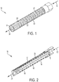
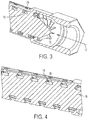
- FIGS. 1-4 schematically depict the details of an example embodiment of a gas-liquid separator 10.
- a fluid mixture 12 comprising a gas and a liquid is shown entering the inlet of a guide member 14.
- Guide vanes 15 deflect the flow of the fluid mixture 12 and redirect it from an axial flow parallel to the axis 16 to a circumferential flow into conduit 18 disposed as an elongated spiral about the axis 16.
- the guide vanes are optional, and the fluid mixture 12 can be allowed to flow into the elongated spiral conduit 18 without assistance from any guide vanes, although an abrupt 90° turn from axial flow to circumferential flow can cause unwanted turbulence and pressure drop.
- the fluid can enter or exit the guide member 14 from a direction perpendicular to the axis so that it is flowing more or less straight into the inlet to elongated spiral conduit 18. It should also be noted that although FIGS. 1-4 depict only a single elongated spiral conduit 18, a plurality of parallel elongated spiral conduits can be utilized.
- centrifugal force acts on both the gas and liquid components of the fluid, and the density difference between the gas and liquid results in the centrifugal force preferentially directing the liquid component radially outward compared to the gas.
- the action of the centrifugal force drives the fluid radially outward through the plurality of radial channels 20, which direct the fluid into contact with a coalescing medium 22 disposed on the outer surface of the guide member 14.
- the internal surfaces of the elongated spiral conduit 18, the coalescing medium 22, and other surfaces in contact with the fluid can be formed from or treated with materials that provide a surface that is wettable by liquid component of the fluid.
- Wettable surfaces can include cleaned metals, plastics, and polymers, any of which may be chemically and/or physically treated.
- a surface is considered wettable or non-wettable by a particular liquid depending on the contact angle between the liquid and the surface.
- a small contact angle e.g., ⁇ 90°
- a large contact angle e.g., > 90°
- Different chemical treatments such as low to mid concentrations acid etching and cleaning
- physical treatments such as laser scanning and coating
- the treatment processes is highly dependent of the liquid and surface being used.
- this can provide a technical effect of promoting liquid flow in a layer along the surface(s) and gas flow through open spaces away from the liquid layer.
- the radial flow paths provided by the radial channels become narrower as the fluid flows from the elongated spiral conduit 18 to the coalescing medium 22.
- such a configuration can provide a technical effect of enhancing liquid phase adhesion to the porous media (coalescing medium) utilizing the surface tension of the liquid that promote phase separation.
- An example embodiment of such narrowing is depicted in cross-sectional view of FIG.
- the radial channels 20 have a relatively larger cross-sectional area at the interface with the elongated spiral conduit 18, and a relatively smaller cross-sectional area at the interface with the coalescing medium.
- the coalescing medium can selected from any of a wide variety of porous media, including but not limited to mesh screens or pads made of various materials such as metal or plastic, woven or non-woven fiber pads, open-cell foams made of various materials such as metal, plastic, or composite materials.
- the dimensions of the coalescing medium can vary depending on the specific properties of the liquid (e.g., density, surface tension properties, etc.) and the gas, and on process design parameters including but not limited to mass flow rates and flow velocities.
- the dimensions or materials of the coalescing medium can vary axially along the axis 16 to accommodate different conditions as the fluid flows along the elongated spiral conduit.
- the dimensions or materials of the coalescing medium can vary radially.
- the coalescing medium can have larger openings (e.g., coarser mesh) relatively closer to the axis 16 and smaller openings (e.g., finer mesh) relatively farther from the axis 16.
- the coalescing medium 22 can comprise a first screen mesh layer 23, and a second screen mesh layer 25 radially outward from the first screen mesh layer and having a finer mesh size than the first screen mesh layer.
- the coalescing medium can comprise a third screen mesh layer 27 disposed between the first and second screen mesh layers and having a finer mesh size than the first screen mesh layer 23 and a courser mesh size than the second screen mesh layer 25.
- the first screen mesh layer can have a mesh size of 20 ⁇ m to 50 ⁇ m
- the second screen mesh layer can have a mesh size of 1 ⁇ m to 5 ⁇ m
- the third screen mesh layer can have a mesh size of 5 ⁇ m to 20 ⁇ m.
- the liquid phase is depleted as it flows out through the radial channels 20, resulting in a liquid-depleted phase 24 exiting from the guide member 14.
- the length of the elongated spiral conduit 18, the number and configuration of the radial channels 20, and the configuration of the coalescing medium 22 can be specified according to design parameters to produce the desired degree of gas- and liquid-depletion in the two phases exiting the gas-liquid separator 10 at anticipated operating conditions.
- a gas-depleted phase can be collected from the coalescing medium 20, for example by accumulation in axial grooves 26 disposed on the outer surface of the gas-liquid separator 10.
- the gas-depleted predominantly liquid phase can be allowed to accumulate in a chamber 28 surrounding the coalescing medium 20 or the gas-liquid separator 10 as shown in FIG. 6 , with or without the use of axial grooves 26.
- a housing 30 is disposed around the gas-liquid separator 10, providing a chamber 28 for accumulation of a liquid or gas-depleted phase, which can exit the chamber 28 as fluid stream 32.
- the gas-liquid phase separator described herein can be utilized in a variety of environments and applications.
- the gas-liquid phase separator can be disposed in a microgravity environment, where it can in some embodiments provide phase separation without moving parts and without assistance from gravity.
- the gas-liquid phase separator can be utilized in a heat transfer system such as a two-phase heat transfer system.
- the heat transfer system is disposed in a microgravity environment.
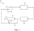
- An example embodiment of a two-phase heat transfer system 34 is schematically depicted in FIG. 7 where fluid flow paths are indicated by arrowed lines connecting the described components. As shown in FIG.
- a pump 36 pumps a heat transfer fluid in a liquid phase to the heat absorption side of an evaporator heat exchanger 38 where heat (e.g., from a conditioned space, not shown) is absorbed as the liquid heat transfer fluid is vaporized.
- the heat transfer fluid can be any type of fluid having target thermodynamic properties, including but not limited to water, ammonia, or organic solvents (e.g., R134A).
- the vaporized heat transfer fluid is transported from the evaporator heat exchanger 38 to the heat rejection side of a condenser heat exchanger 40 where the vaporized heat transfer fluid is condensed to a liquid phase and heat is rejected to a heat sink (not shown, e.g., an external space such as an outdoor space for terrestrial applications or outer space for extra-terrestrial outer space applications).
- a heat sink not shown, e.g., an external space such as an outdoor space for terrestrial applications or outer space for extra-terrestrial outer space applications.
- the design parameters of the condenser heat exchanger 40 are expected to fully condense the vaporized heat transfer fluid, and the liquid phase heat transfer fluid is directed along bypass flow path 42 to the inlet of pump 36.
- the condenser heat exchanger 40 may not fully condense the vaporized heat transfer fluid, resulting in a two-phase flow of heat transfer fluid exiting the heat rejection side of condenser heat exchanger 40.
- Such conditions can occur, for example, when the heat load applied at the evaporator heat exchanger 38 exceeds system design parameters such as during startup or other high heat load conditions, or when the heat absorbing capacities of the heat absorption side of the condenser heat exchanger 40 are reduced below design parameters such as when the heat sink temperature increases. The latter can occur, for example, in an outer space application where the spacecraft is re-oriented such that the condenser heat exchanger 40 is exposed to solar radiation.
- a two-phase gas-liquid fluid can cause cavitation at the pump 36, potentially resulting in damage to the pump. Accordingly, in conditions where a two-phase heat transfer fluid exits the heat rejection side of condenser heat exchanger 40, the flow of the heat transfer fluid can be routed to the gas-liquid phase separator 10 where the vapor phase is removed as liquid-depleted or vapor stream 24, and a vapor-depleted or liquid stream 32 is directed to the inlet of pump 36.
- the liquid-depleted or vapor stream 24 can be recirculated to the inlet of the gas-liquid phase separator 10 or can be stored in a storage vessel (not shown) until normal operating conditions resume, at which time any vapor that has not condensed in the storage vessel can be routed to the inlet of the gas-liquid phase separator 10.
Landscapes
- Engineering & Computer Science (AREA)
- Chemical & Material Sciences (AREA)
- Chemical Kinetics & Catalysis (AREA)
- Physics & Mathematics (AREA)
- Mechanical Engineering (AREA)
- Thermal Sciences (AREA)
- General Engineering & Computer Science (AREA)
- Analytical Chemistry (AREA)
- Power Engineering (AREA)
- Gas Separation By Absorption (AREA)
- Separating Particles In Gases By Inertia (AREA)
Abstract
Description
- The separation of gas and liquid phases from mixtures comprising gas and liquid phases is practiced across a wide variety of applications and materials. Gas-liquid phase separation is used in the oil and gas industry, various chemical manufacturing and treatment processes, heating and cooling applications, fuel management systems, and numerous other applications. For example, in many chemical manufacturing and treatment processes, liquid and gas phases are separated and directed along different paths for further individual processing or treatment.
- Many known gas-liquid separators utilize a coalescing medium such as a screen mesh or other porous medium to separate gas and liquid phases. During operation of such gas-liquid separators, as a gas-liquid mixture makes contact with the coalescing medium, liquid becomes engaged with the coalescing medium. The coalescing medium is typically oriented such that as liquid accumulates on the coalescing medium, liquid droplets become larger until their mass becomes sufficiently high that the force of gravity acting on the droplets causes them to migrate downward through or along the coalescing medium until they reach a collection point at the bottom of the coalescing medium. Such separators, however, are not effective in environments where gravitational forces are either not available (e.g., micro gravity environments such as outer space) or are subject to interference (e.g., by changes in momentum when the separator is in motion such as on a motor vehicle or aircraft).
- According to some embodiments, a device for separating gas and liquid from a mixture comprising gas and liquid phases comprises a fluid guide member comprising a fluid inlet and a fluid outlet connected by a conduit configured as an elongated spiral disposed about an axis. A liquid coalescing medium is disposed on an exterior surface of the fluid guide radially outward from the elongated spiral conduit with respect to the axis. The separator also includes a plurality of radial channels providing radial flow paths for fluid from the elongated spiral conduit to the coalescing medium.
- In some embodiments, a method of separating gas and liquid from a mixture comprising gas and liquid phases, comprising introducing the mixture to the fluid inlet of the above-described gas-liquid separator, receiving a gas-depleted phase at a radially outer surface of the coalescing medium, and receiving a liquid-depleted phase at the fluid outlet.
- According to some embodiments, a heat transfer system comprises a heat transfer fluid flow loop. The heat transfer fluid flow loop comprises an evaporator heat exchanger comprising a heat absorption side comprising a fluid inlet and a fluid outlet for the heat transfer fluid. The evaporator is configured to absorb heat from a conditioned space to vaporize a liquid phase of the heat transfer fluid. A condenser heat exchanger comprising a heat rejection side incudes a fluid inlet in fluid communication with the evaporator heat absorption side outlet, and a fluid outlet for the heat transfer fluid. The condenser is configured to reject heat to a heat sink to condense a gas phase of the heat transfer fluid. The heat transfer system also includes a gas-liquid separator. The gas-liquid separator comprises a fluid guide member comprising a fluid inlet in fluid communication with the condenser heat rejection side outlet, and a fluid outlet. The separator's fluid inlet and fluid outlet are connected by a conduit configured as an elongated spiral disposed about an axis. A liquid coalescing medium is disposed on an exterior surface of the fluid guide radially outward from the elongated spiral conduit with respect to the axis. The separator also includes a plurality of radial channels providing radial flow paths for fluid from the elongated spiral conduit to the coalescing medium. The heat transfer system also includes a pump comprising a fluid inlet in fluid communication with the fluid guide member fluid outlet, and a fluid outlet in fluid communication with the evaporator heat absorption side inlet.
- Subject matter of this disclosure is particularly pointed out and distinctly claimed in the claims at the conclusion of the specification. The foregoing and other features, and advantages of the present disclosure are apparent from the following detailed description taken in conjunction with the accompanying drawings in which:
-
FIG. 1 is a schematic depiction in a perspective view of an example embodiment of a gas-liquid separator; -
FIG. 2 is a perspective cross-section view of the gas-liquid separator ofFIG. 1 ; -
FIG. 3 is a magnified view of a portion of the perspective cross-section ofFIG. 2 ; -
FIG. 4 is a magnified view of a portion of a perspective cross-section of the gas-liquid separator ofFIG. 1 , taken on a different parting line thanFIGS. 2 and3 , through the radial channels; -
FIG. 5 is a cross-section view of a schematic representation of a multilayer coalescing medium; -
FIG. 6 is a perspective view of an example embodiment of a gas-liquid separator that includes a liquid collection chamber; and -
FIG. 7 is a schematic depiction of a heat transfer system including a gas-liquid phase separator. - With reference now to the Figures,
FIGS. 1-4 schematically depict the details of an example embodiment of a gas-liquid separator 10. As shown inFIGS. 1-4 , afluid mixture 12 comprising a gas and a liquid is shown entering the inlet of aguide member 14. Guide vanes 15 deflect the flow of thefluid mixture 12 and redirect it from an axial flow parallel to theaxis 16 to a circumferential flow intoconduit 18 disposed as an elongated spiral about theaxis 16. It should be noted that the guide vanes are optional, and thefluid mixture 12 can be allowed to flow into the elongatedspiral conduit 18 without assistance from any guide vanes, although an abrupt 90° turn from axial flow to circumferential flow can cause unwanted turbulence and pressure drop. In some embodiments (not shown), the fluid can enter or exit theguide member 14 from a direction perpendicular to the axis so that it is flowing more or less straight into the inlet to elongatedspiral conduit 18. It should also be noted that althoughFIGS. 1-4 depict only a single elongatedspiral conduit 18, a plurality of parallel elongated spiral conduits can be utilized. - As the fluid flows through the elongated
spiral conduit 18, centrifugal force acts on both the gas and liquid components of the fluid, and the density difference between the gas and liquid results in the centrifugal force preferentially directing the liquid component radially outward compared to the gas. The action of the centrifugal force drives the fluid radially outward through the plurality ofradial channels 20, which direct the fluid into contact with a coalescingmedium 22 disposed on the outer surface of theguide member 14. The internal surfaces of the elongatedspiral conduit 18, the coalescingmedium 22, and other surfaces in contact with the fluid can be formed from or treated with materials that provide a surface that is wettable by liquid component of the fluid. Wettable surfaces can include cleaned metals, plastics, and polymers, any of which may be chemically and/or physically treated. A surface is considered wettable or non-wettable by a particular liquid depending on the contact angle between the liquid and the surface. A small contact angle (e.g., ≤ 90°) means the surface is wettable, and a large contact angle (e.g., > 90°) means the surface is not wettable and vice versa. Different chemical treatments (such as low to mid concentrations acid etching and cleaning) and physical treatments (such as laser scanning and coating) can be employed to alter the contact angle to make the surface wettable or non-wettable. The treatment processes is highly dependent of the liquid and surface being used. In some embodiments, this can provide a technical effect of promoting liquid flow in a layer along the surface(s) and gas flow through open spaces away from the liquid layer. In some embodiments, the radial flow paths provided by the radial channels become narrower as the fluid flows from the elongatedspiral conduit 18 to the coalescingmedium 22. In some embodiments, such a configuration can provide a technical effect of enhancing liquid phase adhesion to the porous media (coalescing medium) utilizing the surface tension of the liquid that promote phase separation. An example embodiment of such narrowing is depicted in cross-sectional view ofFIG. 4 along a parting line through a group of theradial channels 20, where it is seen that theradial channels 20 have a relatively larger cross-sectional area at the interface with the elongatedspiral conduit 18, and a relatively smaller cross-sectional area at the interface with the coalescing medium. - The coalescing medium can selected from any of a wide variety of porous media, including but not limited to mesh screens or pads made of various materials such as metal or plastic, woven or non-woven fiber pads, open-cell foams made of various materials such as metal, plastic, or composite materials. The dimensions of the coalescing medium can vary depending on the specific properties of the liquid (e.g., density, surface tension properties, etc.) and the gas, and on process design parameters including but not limited to mass flow rates and flow velocities. In some embodiments, the dimensions or materials of the coalescing medium can vary axially along the
axis 16 to accommodate different conditions as the fluid flows along the elongated spiral conduit. In some embodiments, the dimensions or materials of the coalescing medium can vary radially. For example, the coalescing medium can have larger openings (e.g., coarser mesh) relatively closer to theaxis 16 and smaller openings (e.g., finer mesh) relatively farther from theaxis 16. In some embodiments (e.g., as depicted in an example embodiment inFIG. 5 ), the coalescingmedium 22 can comprise a firstscreen mesh layer 23, and a secondscreen mesh layer 25 radially outward from the first screen mesh layer and having a finer mesh size than the first screen mesh layer. In some embodiments, the coalescing medium can comprise a thirdscreen mesh layer 27 disposed between the first and second screen mesh layers and having a finer mesh size than the firstscreen mesh layer 23 and a courser mesh size than the secondscreen mesh layer 25. In some embodiments, the first screen mesh layer can have a mesh size of 20 µm to 50 µm, the second screen mesh layer can have a mesh size of 1 µm to 5 µm, and the third screen mesh layer can have a mesh size of 5 µm to 20 µm. - As the fluid flows along through the elongated
spiral conduit 18, the liquid phase is depleted as it flows out through theradial channels 20, resulting in a liquid-depletedphase 24 exiting from theguide member 14. The length of the elongatedspiral conduit 18, the number and configuration of theradial channels 20, and the configuration of the coalescingmedium 22 can be specified according to design parameters to produce the desired degree of gas- and liquid-depletion in the two phases exiting the gas-liquid separator 10 at anticipated operating conditions. A gas-depleted phase can be collected from the coalescingmedium 20, for example by accumulation in axial grooves 26 disposed on the outer surface of the gas-liquid separator 10. In some embodiments, the gas-depleted predominantly liquid phase can be allowed to accumulate in achamber 28 surrounding the coalescingmedium 20 or the gas-liquid separator 10 as shown inFIG. 6 , with or without the use of axial grooves 26. As shown inFIG. 6 , ahousing 30 is disposed around the gas-liquid separator 10, providing achamber 28 for accumulation of a liquid or gas-depleted phase, which can exit thechamber 28 asfluid stream 32. - The gas-liquid phase separator described herein can be utilized in a variety of environments and applications. In some embodiments, the gas-liquid phase separator can be disposed in a microgravity environment, where it can in some embodiments provide phase separation without moving parts and without assistance from gravity. In some embodiments, the gas-liquid phase separator can be utilized in a heat transfer system such as a two-phase heat transfer system. In some embodiments, the heat transfer system is disposed in a microgravity environment. An example embodiment of a two-phase
heat transfer system 34 is schematically depicted inFIG. 7 where fluid flow paths are indicated by arrowed lines connecting the described components. As shown inFIG. 7 , apump 36 pumps a heat transfer fluid in a liquid phase to the heat absorption side of anevaporator heat exchanger 38 where heat (e.g., from a conditioned space, not shown) is absorbed as the liquid heat transfer fluid is vaporized. The heat transfer fluid can be any type of fluid having target thermodynamic properties, including but not limited to water, ammonia, or organic solvents (e.g., R134A). The vaporized heat transfer fluid is transported from theevaporator heat exchanger 38 to the heat rejection side of acondenser heat exchanger 40 where the vaporized heat transfer fluid is condensed to a liquid phase and heat is rejected to a heat sink (not shown, e.g., an external space such as an outdoor space for terrestrial applications or outer space for extra-terrestrial outer space applications). Under normal operating conditions, the design parameters of thecondenser heat exchanger 40 are expected to fully condense the vaporized heat transfer fluid, and the liquid phase heat transfer fluid is directed alongbypass flow path 42 to the inlet ofpump 36. Under some operating conditions, however, thecondenser heat exchanger 40 may not fully condense the vaporized heat transfer fluid, resulting in a two-phase flow of heat transfer fluid exiting the heat rejection side ofcondenser heat exchanger 40. Such conditions can occur, for example, when the heat load applied at theevaporator heat exchanger 38 exceeds system design parameters such as during startup or other high heat load conditions, or when the heat absorbing capacities of the heat absorption side of thecondenser heat exchanger 40 are reduced below design parameters such as when the heat sink temperature increases. The latter can occur, for example, in an outer space application where the spacecraft is re-oriented such that thecondenser heat exchanger 40 is exposed to solar radiation. A two-phase gas-liquid fluid can cause cavitation at thepump 36, potentially resulting in damage to the pump. Accordingly, in conditions where a two-phase heat transfer fluid exits the heat rejection side ofcondenser heat exchanger 40, the flow of the heat transfer fluid can be routed to the gas-liquid phase separator 10 where the vapor phase is removed as liquid-depleted orvapor stream 24, and a vapor-depleted orliquid stream 32 is directed to the inlet ofpump 36. The liquid-depleted orvapor stream 24 can be recirculated to the inlet of the gas-liquid phase separator 10 or can be stored in a storage vessel (not shown) until normal operating conditions resume, at which time any vapor that has not condensed in the storage vessel can be routed to the inlet of the gas-liquid phase separator 10. - While the present disclosure has been described in detail in connection with only a limited number of embodiments, it should be readily understood that the present disclosure is not limited to such disclosed embodiments. Rather, the present disclosure can be modified to incorporate any number of variations, alterations, substitutions or equivalent arrangements not heretofore described, but which are commensurate with the scope of the present invention as defined by the claims. Additionally, while various embodiments of the present disclosure have been described, it is to be understood that aspects of the present disclosure may include only some of the described embodiments. Accordingly, the present disclosure is not to be seen as limited by the foregoing description, but is only limited by the scope of the appended claims.
Claims (15)
- A device for separating gas and liquid from a mixture comprising gas and liquid phases, comprising
a fluid guide member (14) comprising a fluid inlet and a fluid outlet connected by a conduit configured as an elongated spiral (18) disposed about an axis (16);
a liquid coalescing medium (22) disposed on an exterior surface of the fluid guide radially outward from the elongated spiral conduit with respect to the axis;
a plurality of radial channels (20) providing radial flow paths for fluid from the elongated spiral conduit to the coalescing medium. - The device of claim 1, wherein the coalescing medium comprises a first screen mesh layer (23), and a second screen mesh layer (25) radially outward from the first screen mesh layer and having a finer mesh size than the first screen mesh layer.
- The device of claim 2, further comprising a third screen mesh layer (27) disposed between the first and second screen mesh layers and having a finer mesh size than the first screen mesh layer and a courser mesh size than the second.
- The device of claim 3, wherein the first screen mesh layer has a mesh size of 20 µm to 50 µm, the second screen mesh layer has a mesh size of 1 µm to 5 µm, and the third screen mesh layer has a mesh size of 5 µm to 20 µm.
- The device of any of claims 1-4, further comprising a housing (30) disposed about the fluid guide configured to provide a chamber between the liquid coalescing medium and the housing for collection of liquid from the mixture, the housing further comprising a liquid outlet.
- The device of any of claims 1-5, wherein the radial channels have a larger cross-sectional area at the interface with the spiral conduit and a smaller cross-sectional area at the interface with the coalescing medium.
- The device of any of claims 1-6, wherein the coalescing medium includes a plurality of grooves parallel to the axis at a radially outer surface of the coalescing medium.
- The device of any of claims 1-7, wherein the guide member is configured to receive fluid flow in a direction parallel to the axis, and further comprises guide vanes to redirect axial fluid flow at the fluid inlet to a circumferential fluid flow direction into the elongated spiral conduit.
- The device of any of claims 1-7, wherein the fluid flow inlet is configured to receive fluid flow in a direction perpendicular to the axis and parallel to the elongated spiral conduit at the fluid inlet..
- A system for separating gas and liquid from a mixture comprising gas and liquid phases, comprising the device of any of claims 1-9 disposed in a microgravity environment.
- A heat transfer system, comprising a heat transfer fluid flow loop that comprises:an evaporator heat exchanger (38) comprising a heat absorption side comprising a fluid inlet and a fluid outlet for the heat transfer fluid, the evaporator configured to absorb heat from a conditioned space to vaporize a liquid phase of the heat transfer fluid;a condenser heat exchanger (40) comprising a heat rejection side comprising a fluid inlet in fluid communication with the evaporator heat absorption side outlet, and a fluid outlet for the heat transfer fluid, the condenser configured to reject heat to a heat sink to condense a gas phase of the heat transfer fluid;the gas-liquid separator (10) of any of claims 1-9; anda pump (36) comprising a fluid inlet in fluid communication with the fluid guide member fluid outlet, and a fluid outlet in fluid communication with the evaporator heat absorption side inlet.
- A heat transfer system, comprising the system of claim 11 disposed in a microgravity environment.
- The system of claims 11 or 12, further comprising a fluid bypass (42) around the gas-liquid separator, providing fluid communication between the condenser heat rejection side fluid outlet and the pump inlet.
- A method of separating gas and liquid from a mixture comprising gas and liquid phases, comprising introducing the mixture to the fluid inlet of the device of any of claims 1-9, receiving a gas-depleted phase at a radially outer surface of the coalescing medium, and receiving a liquid-depleted phase at the fluid outlet.
- A method of separating gas and liquid from a mixture comprising gas and liquid phases, comprising introducing the mixture to the fluid inlet of the device of any of claims 1-9 in microgravity conditions, receiving a gas-depleted phase at a radially outer surface of the coalescing medium, and receiving a liquid-depleted phase at the fluid outlet.
Applications Claiming Priority (1)
| Application Number | Priority Date | Filing Date | Title |
|---|---|---|---|
| US15/148,461 US10612824B2 (en) | 2016-05-06 | 2016-05-06 | Gas-liquid phase separator |
Publications (2)
| Publication Number | Publication Date |
|---|---|
| EP3241598A1 true EP3241598A1 (en) | 2017-11-08 |
| EP3241598B1 EP3241598B1 (en) | 2018-12-12 |
Family
ID=58698971
Family Applications (1)
| Application Number | Title | Priority Date | Filing Date |
|---|---|---|---|
| EP17169874.9A Active EP3241598B1 (en) | 2016-05-06 | 2017-05-08 | Gas-liquid phase separator and method of separating a gas and a liquid |
Country Status (2)
| Country | Link |
|---|---|
| US (1) | US10612824B2 (en) |
| EP (1) | EP3241598B1 (en) |
Cited By (2)
| Publication number | Priority date | Publication date | Assignee | Title |
|---|---|---|---|---|
| CN111512101A (en) * | 2017-12-25 | 2020-08-07 | 三菱电机株式会社 | Separator and refrigeration cycle device |
| WO2021102537A1 (en) * | 2019-11-26 | 2021-06-03 | Petróleo Brasileiro S.A. - Petrobras | Coalescing pipe for conveying fluids comprising at least two immiscible phases |
Families Citing this family (7)
| Publication number | Priority date | Publication date | Assignee | Title |
|---|---|---|---|---|
| US10253267B2 (en) * | 2016-04-06 | 2019-04-09 | Purscrub Llc | Separator that removes free liquid and particles from a gas stream |
| US10864993B2 (en) | 2018-10-22 | 2020-12-15 | Hamilton Sunstrand Corporation | Liquid vapor separator |
| JP7750831B2 (en) * | 2019-10-31 | 2025-10-07 | モット・コーポレーション | Two-phase separator device incorporating inertial separation and porous media extraction |
| US11446585B2 (en) * | 2020-06-08 | 2022-09-20 | Hamilton Sundstrand Corporation | Grooved porous media gas trap for terrestrial and microgravity environment |
| CN116182439A (en) * | 2023-01-17 | 2023-05-30 | 广东美的暖通设备有限公司 | Gas-liquid separator and air conditioning system |
| US12551829B2 (en) | 2023-03-28 | 2026-02-17 | Hamilton Sundstrand Space Systems International, Inc. | Fluid separation and condensate control systems |
| CN119617721B (en) * | 2024-12-28 | 2025-09-19 | 广州谷德制冷设备有限公司 | Energy-saving refrigerating unit |
Citations (4)
| Publication number | Priority date | Publication date | Assignee | Title |
|---|---|---|---|---|
| US4482364A (en) * | 1983-05-06 | 1984-11-13 | Martin Reginald | Oil gas/separator |
| CA2221191A1 (en) * | 1995-05-17 | 1996-11-21 | Atlantic Richfield Company | Separator systems for well production fluids |
| US20110048696A1 (en) * | 2008-02-06 | 2011-03-03 | Statoil Asa | Gas-liquid separator |
| WO2014047527A2 (en) * | 2012-09-21 | 2014-03-27 | Ng1 Technologies, Llc | Pipeline systems and methods |
Family Cites Families (22)
| Publication number | Priority date | Publication date | Assignee | Title |
|---|---|---|---|---|
| US2011048A (en) | 1933-06-14 | 1935-08-13 | Campbell Wyant & Cannon Co | Combustion chamber |
| GB2151505A (en) * | 1983-12-21 | 1985-07-24 | John William Brookes | Improvements in oil/gas separators |
| AU2002242188A1 (en) | 2001-02-16 | 2002-09-04 | United Technologies Corporation | Improved aircraft architecture with a reduced bleed aircraft secondary power system |
| US6845630B2 (en) | 2001-02-16 | 2005-01-25 | Hamilton Sundstrand Corporation | Electric power and cooling system for an aircraft |
| US6629428B1 (en) | 2002-10-07 | 2003-10-07 | Honeywell International Inc. | Method of heating for an aircraft electric environmental control system |
| US7326266B2 (en) * | 2003-10-31 | 2008-02-05 | Flair Corporation | Coalescing type filter apparatus and method |
| US7578136B2 (en) | 2004-08-23 | 2009-08-25 | Honeywell International Inc. | Integrated power and pressurization system |
| US7322202B2 (en) | 2004-09-22 | 2008-01-29 | Hamilton Sundstrand Corporation | Electric motor driven supercharger with air cycle air conditioning system |
| US7970497B2 (en) | 2007-03-02 | 2011-06-28 | Honeywell International Inc. | Smart hybrid electric and bleed architecture |
| US20080264084A1 (en) | 2007-04-25 | 2008-10-30 | Honeywell International Inc. | Pressurized closed cooling system |
| DE102007057536B4 (en) | 2007-11-29 | 2011-03-17 | Airbus Operations Gmbh | Air conditioning with hybrid bleed air operation |
| WO2011028108A2 (en) * | 2009-09-04 | 2011-03-10 | Advanced Tail-End Oil Company N.V. | Drained coalescer |
| US8973393B2 (en) | 2009-11-08 | 2015-03-10 | The Boeing Company | System and method for improved cooling efficiency of an aircraft during both ground and flight operation |
| CN105783348B (en) * | 2010-05-27 | 2019-05-17 | Xdx全球有限公司 | Method to the setting bypass of at least one phase separator to carry out heating operation |
| US20120138737A1 (en) | 2010-12-02 | 2012-06-07 | Bruno Louis J | Aircraft power distribution architecture |
| US8500064B2 (en) | 2011-08-10 | 2013-08-06 | Hamilton Sundstrand Corporation | Hybrid power system architecture for an aircraft |
| JP5920179B2 (en) * | 2011-12-05 | 2016-05-18 | 株式会社デンソー | Heat exchanger and heat pump cycle including the same |
| US9254920B2 (en) | 2012-05-30 | 2016-02-09 | General Electric Company | Aircraft energy management system including engine fan discharge air boosted environmental control system |
| US8742605B1 (en) | 2013-02-07 | 2014-06-03 | Hamilton Sundstrand Corporation | Method for aircraft engine start using synchronous generator and constant speed drive |
| EP2986390A1 (en) * | 2013-04-16 | 2016-02-24 | Massachusetts Institute of Technology | System and method for unipolar separation of emulsions and other mixtures |
| US9470218B2 (en) | 2013-05-08 | 2016-10-18 | Hamilton Sundstrand Corporation | Self-cooling loop with electric ram fan for motor driven compressor |
| ITBS20130143A1 (en) * | 2013-10-11 | 2015-04-12 | Turboden Srl | OIL SEPARATOR FROM A WORK FLUID FOR ORC PLANT |
-
2016
- 2016-05-06 US US15/148,461 patent/US10612824B2/en active Active
-
2017
- 2017-05-08 EP EP17169874.9A patent/EP3241598B1/en active Active
Patent Citations (4)
| Publication number | Priority date | Publication date | Assignee | Title |
|---|---|---|---|---|
| US4482364A (en) * | 1983-05-06 | 1984-11-13 | Martin Reginald | Oil gas/separator |
| CA2221191A1 (en) * | 1995-05-17 | 1996-11-21 | Atlantic Richfield Company | Separator systems for well production fluids |
| US20110048696A1 (en) * | 2008-02-06 | 2011-03-03 | Statoil Asa | Gas-liquid separator |
| WO2014047527A2 (en) * | 2012-09-21 | 2014-03-27 | Ng1 Technologies, Llc | Pipeline systems and methods |
Cited By (4)
| Publication number | Priority date | Publication date | Assignee | Title |
|---|---|---|---|---|
| CN111512101A (en) * | 2017-12-25 | 2020-08-07 | 三菱电机株式会社 | Separator and refrigeration cycle device |
| EP3734197A4 (en) * | 2017-12-25 | 2020-12-30 | Mitsubishi Electric Corporation | SEPARATOR AND REFRIGERATION CIRCUIT DEVICE |
| CN111512101B (en) * | 2017-12-25 | 2022-03-04 | 三菱电机株式会社 | Separator and refrigeration cycle device |
| WO2021102537A1 (en) * | 2019-11-26 | 2021-06-03 | Petróleo Brasileiro S.A. - Petrobras | Coalescing pipe for conveying fluids comprising at least two immiscible phases |
Also Published As
| Publication number | Publication date |
|---|---|
| US20170321936A1 (en) | 2017-11-09 |
| EP3241598B1 (en) | 2018-12-12 |
| US10612824B2 (en) | 2020-04-07 |
Similar Documents
| Publication | Publication Date | Title |
|---|---|---|
| EP3241598B1 (en) | Gas-liquid phase separator and method of separating a gas and a liquid | |
| US5314529A (en) | Entrained droplet separator | |
| US20190271513A1 (en) | Multi-layered counterflow expanding microchannel cooling architecture and system thereof | |
| US11137183B2 (en) | Phobic/philic structures in refrigeration systems and liquid vapor separation in refrigeration systems | |
| CN104540570B (en) | Inertial gas-liquid separator and the porous collection matrix being used in inertial gas-liquid separator | |
| EP3369470B1 (en) | Inertial particle separator for air cycle machine | |
| CN107850359B (en) | Evaporator and turbo refrigeration device equipped with the same | |
| JP2007283290A (en) | Air/oil separation element for separating liquid droplet from air and air compressor equipped therewith | |
| Vijayan et al. | CFD modeling and analysis of a two-phase vapor separator: V. Vijayan et al. | |
| EP3524358B1 (en) | Vortex separator and separation method | |
| CN109690227B (en) | Standpipe heat exchanger and heat exchange method | |
| EP3355004B1 (en) | Passive liquid collecting device | |
| CN115362343B (en) | evaporator | |
| US7470300B2 (en) | Duct wall water extractor | |
| EP3643377B1 (en) | Liquid vapor separator | |
| EP3661623B1 (en) | Desorber for air conditioning system having integrated microemulsion-based air dehumidification | |
| RU2275224C2 (en) | Heat and mass exchange apparatus | |
| RU2614897C1 (en) | Condenser separator for two-component two-phase systems | |
| US20250269298A1 (en) | Capillary condensing heat exchanger | |
| KR101805055B1 (en) | Oil demister of heat exchanger type | |
| EP4154965B1 (en) | Passive phase separator with liquid removal chamber | |
| EP4445984A1 (en) | Fluid separation and condensate control systems | |
| US20230039778A1 (en) | Passive phase separator at a heat exchanger output |
Legal Events
| Date | Code | Title | Description |
|---|---|---|---|
| PUAI | Public reference made under article 153(3) epc to a published international application that has entered the european phase |
Free format text: ORIGINAL CODE: 0009012 |
|
| STAA | Information on the status of an ep patent application or granted ep patent |
Free format text: STATUS: THE APPLICATION HAS BEEN PUBLISHED |
|
| AK | Designated contracting states |
Kind code of ref document: A1 Designated state(s): AL AT BE BG CH CY CZ DE DK EE ES FI FR GB GR HR HU IE IS IT LI LT LU LV MC MK MT NL NO PL PT RO RS SE SI SK SM TR |
|
| AX | Request for extension of the european patent |
Extension state: BA ME |
|
| STAA | Information on the status of an ep patent application or granted ep patent |
Free format text: STATUS: REQUEST FOR EXAMINATION WAS MADE |
|
| 17P | Request for examination filed |
Effective date: 20180508 |
|
| RBV | Designated contracting states (corrected) |
Designated state(s): AL AT BE BG CH CY CZ DE DK EE ES FI FR GB GR HR HU IE IS IT LI LT LU LV MC MK MT NL NO PL PT RO RS SE SI SK SM TR |
|
| GRAP | Despatch of communication of intention to grant a patent |
Free format text: ORIGINAL CODE: EPIDOSNIGR1 |
|
| STAA | Information on the status of an ep patent application or granted ep patent |
Free format text: STATUS: GRANT OF PATENT IS INTENDED |
|
| RIC1 | Information provided on ipc code assigned before grant |
Ipc: F25B 39/02 20060101ALI20180614BHEP Ipc: B01D 46/00 20060101ALI20180614BHEP Ipc: F25B 39/04 20060101ALI20180614BHEP Ipc: B01D 19/00 20060101AFI20180614BHEP Ipc: F25B 39/00 20060101ALI20180614BHEP Ipc: F25B 43/00 20060101ALI20180614BHEP Ipc: F25B 13/00 20060101ALI20180614BHEP |
|
| INTG | Intention to grant announced |
Effective date: 20180710 |
|
| GRAS | Grant fee paid |
Free format text: ORIGINAL CODE: EPIDOSNIGR3 |
|
| GRAA | (expected) grant |
Free format text: ORIGINAL CODE: 0009210 |
|
| STAA | Information on the status of an ep patent application or granted ep patent |
Free format text: STATUS: THE PATENT HAS BEEN GRANTED |
|
| AK | Designated contracting states |
Kind code of ref document: B1 Designated state(s): AL AT BE BG CH CY CZ DE DK EE ES FI FR GB GR HR HU IE IS IT LI LT LU LV MC MK MT NL NO PL PT RO RS SE SI SK SM TR |
|
| REG | Reference to a national code |
Ref country code: GB Ref legal event code: FG4D |
|
| REG | Reference to a national code |
Ref country code: CH Ref legal event code: EP |
|
| REG | Reference to a national code |
Ref country code: AT Ref legal event code: REF Ref document number: 1075203 Country of ref document: AT Kind code of ref document: T Effective date: 20181215 |
|
| REG | Reference to a national code |
Ref country code: DE Ref legal event code: R096 Ref document number: 602017001318 Country of ref document: DE |
|
| REG | Reference to a national code |
Ref country code: IE Ref legal event code: FG4D |
|
| REG | Reference to a national code |
Ref country code: NL Ref legal event code: FP |
|
| REG | Reference to a national code |
Ref country code: LT Ref legal event code: MG4D |
|
| PG25 | Lapsed in a contracting state [announced via postgrant information from national office to epo] |
Ref country code: ES Free format text: LAPSE BECAUSE OF FAILURE TO SUBMIT A TRANSLATION OF THE DESCRIPTION OR TO PAY THE FEE WITHIN THE PRESCRIBED TIME-LIMIT Effective date: 20181212 Ref country code: LV Free format text: LAPSE BECAUSE OF FAILURE TO SUBMIT A TRANSLATION OF THE DESCRIPTION OR TO PAY THE FEE WITHIN THE PRESCRIBED TIME-LIMIT Effective date: 20181212 Ref country code: HR Free format text: LAPSE BECAUSE OF FAILURE TO SUBMIT A TRANSLATION OF THE DESCRIPTION OR TO PAY THE FEE WITHIN THE PRESCRIBED TIME-LIMIT Effective date: 20181212 Ref country code: NO Free format text: LAPSE BECAUSE OF FAILURE TO SUBMIT A TRANSLATION OF THE DESCRIPTION OR TO PAY THE FEE WITHIN THE PRESCRIBED TIME-LIMIT Effective date: 20190312 Ref country code: BG Free format text: LAPSE BECAUSE OF FAILURE TO SUBMIT A TRANSLATION OF THE DESCRIPTION OR TO PAY THE FEE WITHIN THE PRESCRIBED TIME-LIMIT Effective date: 20190312 Ref country code: FI Free format text: LAPSE BECAUSE OF FAILURE TO SUBMIT A TRANSLATION OF THE DESCRIPTION OR TO PAY THE FEE WITHIN THE PRESCRIBED TIME-LIMIT Effective date: 20181212 Ref country code: LT Free format text: LAPSE BECAUSE OF FAILURE TO SUBMIT A TRANSLATION OF THE DESCRIPTION OR TO PAY THE FEE WITHIN THE PRESCRIBED TIME-LIMIT Effective date: 20181212 |
|
| REG | Reference to a national code |
Ref country code: AT Ref legal event code: MK05 Ref document number: 1075203 Country of ref document: AT Kind code of ref document: T Effective date: 20181212 |
|
| PG25 | Lapsed in a contracting state [announced via postgrant information from national office to epo] |
Ref country code: SE Free format text: LAPSE BECAUSE OF FAILURE TO SUBMIT A TRANSLATION OF THE DESCRIPTION OR TO PAY THE FEE WITHIN THE PRESCRIBED TIME-LIMIT Effective date: 20181212 Ref country code: RS Free format text: LAPSE BECAUSE OF FAILURE TO SUBMIT A TRANSLATION OF THE DESCRIPTION OR TO PAY THE FEE WITHIN THE PRESCRIBED TIME-LIMIT Effective date: 20181212 Ref country code: GR Free format text: LAPSE BECAUSE OF FAILURE TO SUBMIT A TRANSLATION OF THE DESCRIPTION OR TO PAY THE FEE WITHIN THE PRESCRIBED TIME-LIMIT Effective date: 20190313 Ref country code: AL Free format text: LAPSE BECAUSE OF FAILURE TO SUBMIT A TRANSLATION OF THE DESCRIPTION OR TO PAY THE FEE WITHIN THE PRESCRIBED TIME-LIMIT Effective date: 20181212 |
|
| PG25 | Lapsed in a contracting state [announced via postgrant information from national office to epo] |
Ref country code: PT Free format text: LAPSE BECAUSE OF FAILURE TO SUBMIT A TRANSLATION OF THE DESCRIPTION OR TO PAY THE FEE WITHIN THE PRESCRIBED TIME-LIMIT Effective date: 20190412 Ref country code: CZ Free format text: LAPSE BECAUSE OF FAILURE TO SUBMIT A TRANSLATION OF THE DESCRIPTION OR TO PAY THE FEE WITHIN THE PRESCRIBED TIME-LIMIT Effective date: 20181212 Ref country code: IT Free format text: LAPSE BECAUSE OF FAILURE TO SUBMIT A TRANSLATION OF THE DESCRIPTION OR TO PAY THE FEE WITHIN THE PRESCRIBED TIME-LIMIT Effective date: 20181212 Ref country code: PL Free format text: LAPSE BECAUSE OF FAILURE TO SUBMIT A TRANSLATION OF THE DESCRIPTION OR TO PAY THE FEE WITHIN THE PRESCRIBED TIME-LIMIT Effective date: 20181212 |
|
| PG25 | Lapsed in a contracting state [announced via postgrant information from national office to epo] |
Ref country code: SM Free format text: LAPSE BECAUSE OF FAILURE TO SUBMIT A TRANSLATION OF THE DESCRIPTION OR TO PAY THE FEE WITHIN THE PRESCRIBED TIME-LIMIT Effective date: 20181212 Ref country code: SK Free format text: LAPSE BECAUSE OF FAILURE TO SUBMIT A TRANSLATION OF THE DESCRIPTION OR TO PAY THE FEE WITHIN THE PRESCRIBED TIME-LIMIT Effective date: 20181212 Ref country code: EE Free format text: LAPSE BECAUSE OF FAILURE TO SUBMIT A TRANSLATION OF THE DESCRIPTION OR TO PAY THE FEE WITHIN THE PRESCRIBED TIME-LIMIT Effective date: 20181212 Ref country code: RO Free format text: LAPSE BECAUSE OF FAILURE TO SUBMIT A TRANSLATION OF THE DESCRIPTION OR TO PAY THE FEE WITHIN THE PRESCRIBED TIME-LIMIT Effective date: 20181212 Ref country code: IS Free format text: LAPSE BECAUSE OF FAILURE TO SUBMIT A TRANSLATION OF THE DESCRIPTION OR TO PAY THE FEE WITHIN THE PRESCRIBED TIME-LIMIT Effective date: 20190412 |
|
| REG | Reference to a national code |
Ref country code: DE Ref legal event code: R097 Ref document number: 602017001318 Country of ref document: DE |
|
| PLBE | No opposition filed within time limit |
Free format text: ORIGINAL CODE: 0009261 |
|
| STAA | Information on the status of an ep patent application or granted ep patent |
Free format text: STATUS: NO OPPOSITION FILED WITHIN TIME LIMIT |
|
| PG25 | Lapsed in a contracting state [announced via postgrant information from national office to epo] |
Ref country code: SI Free format text: LAPSE BECAUSE OF FAILURE TO SUBMIT A TRANSLATION OF THE DESCRIPTION OR TO PAY THE FEE WITHIN THE PRESCRIBED TIME-LIMIT Effective date: 20181212 Ref country code: AT Free format text: LAPSE BECAUSE OF FAILURE TO SUBMIT A TRANSLATION OF THE DESCRIPTION OR TO PAY THE FEE WITHIN THE PRESCRIBED TIME-LIMIT Effective date: 20181212 Ref country code: DK Free format text: LAPSE BECAUSE OF FAILURE TO SUBMIT A TRANSLATION OF THE DESCRIPTION OR TO PAY THE FEE WITHIN THE PRESCRIBED TIME-LIMIT Effective date: 20181212 |
|
| 26N | No opposition filed |
Effective date: 20190913 |
|
| PG25 | Lapsed in a contracting state [announced via postgrant information from national office to epo] |
Ref country code: MC Free format text: LAPSE BECAUSE OF FAILURE TO SUBMIT A TRANSLATION OF THE DESCRIPTION OR TO PAY THE FEE WITHIN THE PRESCRIBED TIME-LIMIT Effective date: 20181212 |
|
| REG | Reference to a national code |
Ref country code: BE Ref legal event code: MM Effective date: 20190531 |
|
| PG25 | Lapsed in a contracting state [announced via postgrant information from national office to epo] |
Ref country code: LU Free format text: LAPSE BECAUSE OF NON-PAYMENT OF DUE FEES Effective date: 20190508 |
|
| PG25 | Lapsed in a contracting state [announced via postgrant information from national office to epo] |
Ref country code: TR Free format text: LAPSE BECAUSE OF FAILURE TO SUBMIT A TRANSLATION OF THE DESCRIPTION OR TO PAY THE FEE WITHIN THE PRESCRIBED TIME-LIMIT Effective date: 20181212 |
|
| PG25 | Lapsed in a contracting state [announced via postgrant information from national office to epo] |
Ref country code: IE Free format text: LAPSE BECAUSE OF NON-PAYMENT OF DUE FEES Effective date: 20190508 |
|
| PG25 | Lapsed in a contracting state [announced via postgrant information from national office to epo] |
Ref country code: BE Free format text: LAPSE BECAUSE OF NON-PAYMENT OF DUE FEES Effective date: 20190531 |
|
| PG25 | Lapsed in a contracting state [announced via postgrant information from national office to epo] |
Ref country code: LI Free format text: LAPSE BECAUSE OF NON-PAYMENT OF DUE FEES Effective date: 20200531 Ref country code: CH Free format text: LAPSE BECAUSE OF NON-PAYMENT OF DUE FEES Effective date: 20200531 |
|
| PG25 | Lapsed in a contracting state [announced via postgrant information from national office to epo] |
Ref country code: CY Free format text: LAPSE BECAUSE OF FAILURE TO SUBMIT A TRANSLATION OF THE DESCRIPTION OR TO PAY THE FEE WITHIN THE PRESCRIBED TIME-LIMIT Effective date: 20181212 |
|
| PG25 | Lapsed in a contracting state [announced via postgrant information from national office to epo] |
Ref country code: HU Free format text: LAPSE BECAUSE OF FAILURE TO SUBMIT A TRANSLATION OF THE DESCRIPTION OR TO PAY THE FEE WITHIN THE PRESCRIBED TIME-LIMIT; INVALID AB INITIO Effective date: 20170508 Ref country code: MT Free format text: LAPSE BECAUSE OF FAILURE TO SUBMIT A TRANSLATION OF THE DESCRIPTION OR TO PAY THE FEE WITHIN THE PRESCRIBED TIME-LIMIT Effective date: 20181212 |
|
| PG25 | Lapsed in a contracting state [announced via postgrant information from national office to epo] |
Ref country code: MK Free format text: LAPSE BECAUSE OF FAILURE TO SUBMIT A TRANSLATION OF THE DESCRIPTION OR TO PAY THE FEE WITHIN THE PRESCRIBED TIME-LIMIT Effective date: 20181212 |
|
| P01 | Opt-out of the competence of the unified patent court (upc) registered |
Effective date: 20230522 |
|
| PGFP | Annual fee paid to national office [announced via postgrant information from national office to epo] |
Ref country code: NL Payment date: 20250423 Year of fee payment: 9 |
|
| PGFP | Annual fee paid to national office [announced via postgrant information from national office to epo] |
Ref country code: DE Payment date: 20250423 Year of fee payment: 9 |
|
| PGFP | Annual fee paid to national office [announced via postgrant information from national office to epo] |
Ref country code: GB Payment date: 20250423 Year of fee payment: 9 |
|
| PGFP | Annual fee paid to national office [announced via postgrant information from national office to epo] |
Ref country code: FR Payment date: 20250423 Year of fee payment: 9 |