EP3240853B1 - Aggregates of diamond with vitrified bond - Google Patents
Aggregates of diamond with vitrified bond Download PDFInfo
- Publication number
- EP3240853B1 EP3240853B1 EP15876343.3A EP15876343A EP3240853B1 EP 3240853 B1 EP3240853 B1 EP 3240853B1 EP 15876343 A EP15876343 A EP 15876343A EP 3240853 B1 EP3240853 B1 EP 3240853B1
- Authority
- EP
- European Patent Office
- Prior art keywords
- abrasive
- aggregate
- particles
- less
- aggregates
- Prior art date
- Legal status (The legal status is an assumption and is not a legal conclusion. Google has not performed a legal analysis and makes no representation as to the accuracy of the status listed.)
- Active
Links
- 239000010432 diamond Substances 0.000 title claims description 51
- 229910003460 diamond Inorganic materials 0.000 title description 21
- 239000002245 particle Substances 0.000 claims description 126
- 239000000203 mixture Substances 0.000 claims description 105
- 239000011230 binding agent Substances 0.000 claims description 85
- 239000008187 granular material Substances 0.000 claims description 55
- 239000002243 precursor Substances 0.000 claims description 54
- 239000003607 modifier Substances 0.000 claims description 29
- 229910010271 silicon carbide Inorganic materials 0.000 claims description 29
- HBMJWWWQQXIZIP-UHFFFAOYSA-N silicon carbide Chemical compound [Si+]#[C-] HBMJWWWQQXIZIP-UHFFFAOYSA-N 0.000 claims description 26
- 238000000034 method Methods 0.000 claims description 21
- 238000005245 sintering Methods 0.000 claims description 16
- PNEYBMLMFCGWSK-UHFFFAOYSA-N aluminium oxide Inorganic materials [O-2].[O-2].[O-2].[Al+3].[Al+3] PNEYBMLMFCGWSK-UHFFFAOYSA-N 0.000 claims description 12
- 229910052684 Cerium Inorganic materials 0.000 claims description 10
- GWXLDORMOJMVQZ-UHFFFAOYSA-N cerium Chemical compound [Ce] GWXLDORMOJMVQZ-UHFFFAOYSA-N 0.000 claims description 9
- 238000002156 mixing Methods 0.000 claims description 7
- 238000007493 shaping process Methods 0.000 claims description 7
- 239000002253 acid Substances 0.000 claims description 2
- QSHDDOUJBYECFT-UHFFFAOYSA-N mercury Chemical compound [Hg] QSHDDOUJBYECFT-UHFFFAOYSA-N 0.000 claims description 2
- 229910052753 mercury Inorganic materials 0.000 claims description 2
- 230000007935 neutral effect Effects 0.000 claims description 2
- 238000002459 porosimetry Methods 0.000 claims description 2
- 239000000835 fiber Substances 0.000 description 27
- 239000011521 glass Substances 0.000 description 25
- 239000003082 abrasive agent Substances 0.000 description 17
- 239000010410 layer Substances 0.000 description 17
- VYPSYNLAJGMNEJ-UHFFFAOYSA-N Silicium dioxide Chemical compound O=[Si]=O VYPSYNLAJGMNEJ-UHFFFAOYSA-N 0.000 description 16
- 239000000463 material Substances 0.000 description 16
- 238000012360 testing method Methods 0.000 description 16
- JKWMSGQKBLHBQQ-UHFFFAOYSA-N diboron trioxide Chemical compound O=BOB=O JKWMSGQKBLHBQQ-UHFFFAOYSA-N 0.000 description 13
- 238000000227 grinding Methods 0.000 description 8
- 239000004615 ingredient Substances 0.000 description 8
- 239000000843 powder Substances 0.000 description 8
- 239000000377 silicon dioxide Substances 0.000 description 8
- QPLDLSVMHZLSFG-UHFFFAOYSA-N Copper oxide Chemical compound [Cu]=O QPLDLSVMHZLSFG-UHFFFAOYSA-N 0.000 description 7
- 239000011248 coating agent Substances 0.000 description 7
- 238000000576 coating method Methods 0.000 description 7
- 238000001878 scanning electron micrograph Methods 0.000 description 7
- 235000012239 silicon dioxide Nutrition 0.000 description 7
- 150000003624 transition metals Chemical group 0.000 description 7
- GWEVSGVZZGPLCZ-UHFFFAOYSA-N Titan oxide Chemical compound O=[Ti]=O GWEVSGVZZGPLCZ-UHFFFAOYSA-N 0.000 description 6
- GNTDGMZSJNCJKK-UHFFFAOYSA-N divanadium pentaoxide Chemical compound O=[V](=O)O[V](=O)=O GNTDGMZSJNCJKK-UHFFFAOYSA-N 0.000 description 6
- OKTJSMMVPCPJKN-UHFFFAOYSA-N Carbon Chemical compound [C] OKTJSMMVPCPJKN-UHFFFAOYSA-N 0.000 description 5
- QVQLCTNNEUAWMS-UHFFFAOYSA-N barium oxide Chemical compound [Ba]=O QVQLCTNNEUAWMS-UHFFFAOYSA-N 0.000 description 5
- 230000009286 beneficial effect Effects 0.000 description 5
- QDOXWKRWXJOMAK-UHFFFAOYSA-N dichromium trioxide Chemical compound O=[Cr]O[Cr]=O QDOXWKRWXJOMAK-UHFFFAOYSA-N 0.000 description 5
- 238000010304 firing Methods 0.000 description 5
- CPLXHLVBOLITMK-UHFFFAOYSA-N magnesium oxide Inorganic materials [Mg]=O CPLXHLVBOLITMK-UHFFFAOYSA-N 0.000 description 5
- 229910052751 metal Inorganic materials 0.000 description 5
- 239000002184 metal Substances 0.000 description 5
- JKQOBWVOAYFWKG-UHFFFAOYSA-N molybdenum trioxide Chemical compound O=[Mo](=O)=O JKQOBWVOAYFWKG-UHFFFAOYSA-N 0.000 description 5
- 229920005989 resin Polymers 0.000 description 5
- 239000011347 resin Substances 0.000 description 5
- XLOMVQKBTHCTTD-UHFFFAOYSA-N Zinc monoxide Chemical compound [Zn]=O XLOMVQKBTHCTTD-UHFFFAOYSA-N 0.000 description 4
- 230000002378 acidificating effect Effects 0.000 description 4
- ODINCKMPIJJUCX-UHFFFAOYSA-N calcium oxide Inorganic materials [Ca]=O ODINCKMPIJJUCX-UHFFFAOYSA-N 0.000 description 4
- 230000001186 cumulative effect Effects 0.000 description 4
- NUJOXMJBOLGQSY-UHFFFAOYSA-N manganese dioxide Chemical compound O=[Mn]=O NUJOXMJBOLGQSY-UHFFFAOYSA-N 0.000 description 4
- TWNQGVIAIRXVLR-UHFFFAOYSA-N oxo(oxoalumanyloxy)alumane Chemical compound O=[Al]O[Al]=O TWNQGVIAIRXVLR-UHFFFAOYSA-N 0.000 description 4
- GNRSAWUEBMWBQH-UHFFFAOYSA-N oxonickel Chemical compound [Ni]=O GNRSAWUEBMWBQH-UHFFFAOYSA-N 0.000 description 4
- 229910052723 transition metal Inorganic materials 0.000 description 4
- UONOETXJSWQNOL-UHFFFAOYSA-N tungsten carbide Chemical compound [W+]#[C-] UONOETXJSWQNOL-UHFFFAOYSA-N 0.000 description 4
- 239000000654 additive Substances 0.000 description 3
- 238000013019 agitation Methods 0.000 description 3
- 239000000292 calcium oxide Substances 0.000 description 3
- 235000012255 calcium oxide Nutrition 0.000 description 3
- 238000009826 distribution Methods 0.000 description 3
- 238000001035 drying Methods 0.000 description 3
- 229910002804 graphite Inorganic materials 0.000 description 3
- 239000010439 graphite Substances 0.000 description 3
- 239000000395 magnesium oxide Substances 0.000 description 3
- 239000011148 porous material Substances 0.000 description 3
- 239000000047 product Substances 0.000 description 3
- IATRAKWUXMZMIY-UHFFFAOYSA-N strontium oxide Chemical compound [O-2].[Sr+2] IATRAKWUXMZMIY-UHFFFAOYSA-N 0.000 description 3
- RUDFQVOCFDJEEF-UHFFFAOYSA-N yttrium(III) oxide Inorganic materials [O-2].[O-2].[O-2].[Y+3].[Y+3] RUDFQVOCFDJEEF-UHFFFAOYSA-N 0.000 description 3
- 235000014692 zinc oxide Nutrition 0.000 description 3
- 239000011787 zinc oxide Substances 0.000 description 3
- 239000002202 Polyethylene glycol Substances 0.000 description 2
- MCMNRKCIXSYSNV-UHFFFAOYSA-N ZrO2 Inorganic materials O=[Zr]=O MCMNRKCIXSYSNV-UHFFFAOYSA-N 0.000 description 2
- 239000006061 abrasive grain Substances 0.000 description 2
- 229910000272 alkali metal oxide Inorganic materials 0.000 description 2
- 239000012298 atmosphere Substances 0.000 description 2
- 239000000919 ceramic Substances 0.000 description 2
- IUYLTEAJCNAMJK-UHFFFAOYSA-N cobalt(2+);oxygen(2-) Chemical compound [O-2].[Co+2] IUYLTEAJCNAMJK-UHFFFAOYSA-N 0.000 description 2
- IVMYJDGYRUAWML-UHFFFAOYSA-N cobalt(II) oxide Inorganic materials [Co]=O IVMYJDGYRUAWML-UHFFFAOYSA-N 0.000 description 2
- 238000010586 diagram Methods 0.000 description 2
- 230000000694 effects Effects 0.000 description 2
- 230000009477 glass transition Effects 0.000 description 2
- 229910001947 lithium oxide Inorganic materials 0.000 description 2
- 238000004519 manufacturing process Methods 0.000 description 2
- 239000011159 matrix material Substances 0.000 description 2
- 230000003647 oxidation Effects 0.000 description 2
- 238000007254 oxidation reaction Methods 0.000 description 2
- RVTZCBVAJQQJTK-UHFFFAOYSA-N oxygen(2-);zirconium(4+) Chemical compound [O-2].[O-2].[Zr+4] RVTZCBVAJQQJTK-UHFFFAOYSA-N 0.000 description 2
- 238000005498 polishing Methods 0.000 description 2
- 229920001223 polyethylene glycol Polymers 0.000 description 2
- CHWRSCGUEQEHOH-UHFFFAOYSA-N potassium oxide Chemical compound [O-2].[K+].[K+] CHWRSCGUEQEHOH-UHFFFAOYSA-N 0.000 description 2
- 239000002002 slurry Substances 0.000 description 2
- 239000012209 synthetic fiber Substances 0.000 description 2
- 229920002994 synthetic fiber Polymers 0.000 description 2
- DLYUQMMRRRQYAE-UHFFFAOYSA-N tetraphosphorus decaoxide Chemical compound O1P(O2)(=O)OP3(=O)OP1(=O)OP2(=O)O3 DLYUQMMRRRQYAE-UHFFFAOYSA-N 0.000 description 2
- NIXOWILDQLNWCW-UHFFFAOYSA-M Acrylate Chemical compound [O-]C(=O)C=C NIXOWILDQLNWCW-UHFFFAOYSA-M 0.000 description 1
- 229920000178 Acrylic resin Polymers 0.000 description 1
- 239000004925 Acrylic resin Substances 0.000 description 1
- 229910052580 B4C Inorganic materials 0.000 description 1
- 241000907788 Cordia gerascanthus Species 0.000 description 1
- 229920000877 Melamine resin Polymers 0.000 description 1
- KWYUFKZDYYNOTN-UHFFFAOYSA-M Potassium hydroxide Chemical compound [OH-].[K+] KWYUFKZDYYNOTN-UHFFFAOYSA-M 0.000 description 1
- 229920001807 Urea-formaldehyde Polymers 0.000 description 1
- 239000003513 alkali Substances 0.000 description 1
- 230000000844 anti-bacterial effect Effects 0.000 description 1
- 239000002216 antistatic agent Substances 0.000 description 1
- 239000007864 aqueous solution Substances 0.000 description 1
- 239000003899 bactericide agent Substances 0.000 description 1
- 230000015572 biosynthetic process Effects 0.000 description 1
- INAHAJYZKVIDIZ-UHFFFAOYSA-N boron carbide Chemical compound B12B3B4C32B41 INAHAJYZKVIDIZ-UHFFFAOYSA-N 0.000 description 1
- 229940105847 calamine Drugs 0.000 description 1
- BRPQOXSCLDDYGP-UHFFFAOYSA-N calcium oxide Chemical compound [O-2].[Ca+2] BRPQOXSCLDDYGP-UHFFFAOYSA-N 0.000 description 1
- 229910052799 carbon Inorganic materials 0.000 description 1
- 238000005266 casting Methods 0.000 description 1
- 239000011195 cermet Substances 0.000 description 1
- 239000011247 coating layer Substances 0.000 description 1
- 239000003086 colorant Substances 0.000 description 1
- 239000002131 composite material Substances 0.000 description 1
- 238000001816 cooling Methods 0.000 description 1
- 229960004643 cupric oxide Drugs 0.000 description 1
- 238000005520 cutting process Methods 0.000 description 1
- 239000003822 epoxy resin Substances 0.000 description 1
- 238000001125 extrusion Methods 0.000 description 1
- 239000004744 fabric Substances 0.000 description 1
- 239000000945 filler Substances 0.000 description 1
- 239000012467 final product Substances 0.000 description 1
- 230000004907 flux Effects 0.000 description 1
- 239000000417 fungicide Substances 0.000 description 1
- 239000003292 glue Substances 0.000 description 1
- -1 grinding aids Substances 0.000 description 1
- LNEPOXFFQSENCJ-UHFFFAOYSA-N haloperidol Chemical compound C1CC(O)(C=2C=CC(Cl)=CC=2)CCN1CCCC(=O)C1=CC=C(F)C=C1 LNEPOXFFQSENCJ-UHFFFAOYSA-N 0.000 description 1
- 229910052864 hemimorphite Inorganic materials 0.000 description 1
- 238000005470 impregnation Methods 0.000 description 1
- 239000000411 inducer Substances 0.000 description 1
- LIKBJVNGSGBSGK-UHFFFAOYSA-N iron(3+);oxygen(2-) Chemical compound [O-2].[O-2].[O-2].[Fe+3].[Fe+3] LIKBJVNGSGBSGK-UHFFFAOYSA-N 0.000 description 1
- FUJCRWPEOMXPAD-UHFFFAOYSA-N lithium oxide Chemical compound [Li+].[Li+].[O-2] FUJCRWPEOMXPAD-UHFFFAOYSA-N 0.000 description 1
- 239000000314 lubricant Substances 0.000 description 1
- AXZKOIWUVFPNLO-UHFFFAOYSA-N magnesium;oxygen(2-) Chemical compound [O-2].[Mg+2] AXZKOIWUVFPNLO-UHFFFAOYSA-N 0.000 description 1
- 239000004570 mortar (masonry) Substances 0.000 description 1
- SIWVEOZUMHYXCS-UHFFFAOYSA-N oxo(oxoyttriooxy)yttrium Chemical compound O=[Y]O[Y]=O SIWVEOZUMHYXCS-UHFFFAOYSA-N 0.000 description 1
- ISWSIDIOOBJBQZ-UHFFFAOYSA-N phenol group Chemical group C1(=CC=CC=C1)O ISWSIDIOOBJBQZ-UHFFFAOYSA-N 0.000 description 1
- 229920001568 phenolic resin Polymers 0.000 description 1
- 239000005011 phenolic resin Substances 0.000 description 1
- 239000000049 pigment Substances 0.000 description 1
- 239000004014 plasticizer Substances 0.000 description 1
- 229920000647 polyepoxide Polymers 0.000 description 1
- 229920002635 polyurethane Polymers 0.000 description 1
- 239000004814 polyurethane Substances 0.000 description 1
- 229940072033 potash Drugs 0.000 description 1
- BWHMMNNQKKPAPP-UHFFFAOYSA-L potassium carbonate Substances [K+].[K+].[O-]C([O-])=O BWHMMNNQKKPAPP-UHFFFAOYSA-L 0.000 description 1
- 235000015320 potassium carbonate Nutrition 0.000 description 1
- 229910001950 potassium oxide Inorganic materials 0.000 description 1
- 238000002360 preparation method Methods 0.000 description 1
- 238000003825 pressing Methods 0.000 description 1
- 238000012216 screening Methods 0.000 description 1
- 238000007873 sieving Methods 0.000 description 1
- KKCBUQHMOMHUOY-UHFFFAOYSA-N sodium oxide Chemical compound [O-2].[Na+].[Na+] KKCBUQHMOMHUOY-UHFFFAOYSA-N 0.000 description 1
- 239000007787 solid Substances 0.000 description 1
- 239000000243 solution Substances 0.000 description 1
- 241000894007 species Species 0.000 description 1
- 239000000126 substance Substances 0.000 description 1
- 239000004094 surface-active agent Substances 0.000 description 1
- 229920002803 thermoplastic polyurethane Polymers 0.000 description 1
- 239000004408 titanium dioxide Substances 0.000 description 1
- XLYOFNOQVPJJNP-UHFFFAOYSA-N water Substances O XLYOFNOQVPJJNP-UHFFFAOYSA-N 0.000 description 1
- CPYIZQLXMGRKSW-UHFFFAOYSA-N zinc;iron(3+);oxygen(2-) Chemical compound [O-2].[O-2].[O-2].[O-2].[Fe+3].[Fe+3].[Zn+2] CPYIZQLXMGRKSW-UHFFFAOYSA-N 0.000 description 1
Images


Classifications
-
- C—CHEMISTRY; METALLURGY
- C09—DYES; PAINTS; POLISHES; NATURAL RESINS; ADHESIVES; COMPOSITIONS NOT OTHERWISE PROVIDED FOR; APPLICATIONS OF MATERIALS NOT OTHERWISE PROVIDED FOR
- C09K—MATERIALS FOR MISCELLANEOUS APPLICATIONS, NOT PROVIDED FOR ELSEWHERE
- C09K3/00—Materials not provided for elsewhere
- C09K3/14—Anti-slip materials; Abrasives
- C09K3/1436—Composite particles, e.g. coated particles
-
- B—PERFORMING OPERATIONS; TRANSPORTING
- B24—GRINDING; POLISHING
- B24D—TOOLS FOR GRINDING, BUFFING OR SHARPENING
- B24D3/00—Physical features of abrasive bodies, or sheets, e.g. abrasive surfaces of special nature; Abrasive bodies or sheets characterised by their constituents
- B24D3/02—Physical features of abrasive bodies, or sheets, e.g. abrasive surfaces of special nature; Abrasive bodies or sheets characterised by their constituents the constituent being used as bonding agent
- B24D3/04—Physical features of abrasive bodies, or sheets, e.g. abrasive surfaces of special nature; Abrasive bodies or sheets characterised by their constituents the constituent being used as bonding agent and being essentially inorganic
- B24D3/14—Physical features of abrasive bodies, or sheets, e.g. abrasive surfaces of special nature; Abrasive bodies or sheets characterised by their constituents the constituent being used as bonding agent and being essentially inorganic ceramic, i.e. vitrified bondings
- B24D3/18—Physical features of abrasive bodies, or sheets, e.g. abrasive surfaces of special nature; Abrasive bodies or sheets characterised by their constituents the constituent being used as bonding agent and being essentially inorganic ceramic, i.e. vitrified bondings for porous or cellular structure
-
- B—PERFORMING OPERATIONS; TRANSPORTING
- B24—GRINDING; POLISHING
- B24D—TOOLS FOR GRINDING, BUFFING OR SHARPENING
- B24D11/00—Constructional features of flexible abrasive materials; Special features in the manufacture of such materials
-
- B—PERFORMING OPERATIONS; TRANSPORTING
- B24—GRINDING; POLISHING
- B24D—TOOLS FOR GRINDING, BUFFING OR SHARPENING
- B24D11/00—Constructional features of flexible abrasive materials; Special features in the manufacture of such materials
- B24D11/001—Manufacture of flexible abrasive materials
- B24D11/005—Making abrasive webs
-
- B—PERFORMING OPERATIONS; TRANSPORTING
- B24—GRINDING; POLISHING
- B24D—TOOLS FOR GRINDING, BUFFING OR SHARPENING
- B24D11/00—Constructional features of flexible abrasive materials; Special features in the manufacture of such materials
- B24D11/02—Backings, e.g. foils, webs, mesh fabrics
-
- B—PERFORMING OPERATIONS; TRANSPORTING
- B24—GRINDING; POLISHING
- B24D—TOOLS FOR GRINDING, BUFFING OR SHARPENING
- B24D3/00—Physical features of abrasive bodies, or sheets, e.g. abrasive surfaces of special nature; Abrasive bodies or sheets characterised by their constituents
- B24D3/001—Physical features of abrasive bodies, or sheets, e.g. abrasive surfaces of special nature; Abrasive bodies or sheets characterised by their constituents the constituent being used as supporting member
- B24D3/002—Flexible supporting members, e.g. paper, woven, plastic materials
-
- B—PERFORMING OPERATIONS; TRANSPORTING
- B24—GRINDING; POLISHING
- B24D—TOOLS FOR GRINDING, BUFFING OR SHARPENING
- B24D3/00—Physical features of abrasive bodies, or sheets, e.g. abrasive surfaces of special nature; Abrasive bodies or sheets characterised by their constituents
- B24D3/02—Physical features of abrasive bodies, or sheets, e.g. abrasive surfaces of special nature; Abrasive bodies or sheets characterised by their constituents the constituent being used as bonding agent
- B24D3/04—Physical features of abrasive bodies, or sheets, e.g. abrasive surfaces of special nature; Abrasive bodies or sheets characterised by their constituents the constituent being used as bonding agent and being essentially inorganic
- B24D3/14—Physical features of abrasive bodies, or sheets, e.g. abrasive surfaces of special nature; Abrasive bodies or sheets characterised by their constituents the constituent being used as bonding agent and being essentially inorganic ceramic, i.e. vitrified bondings
Definitions
- the present disclosure relates to abrasive aggregates of diamond with a vitrified bond, and methods of making and using such abrasive aggregates, including in abrasive articles.
- Abrasive tools can use an abrasive to shape or finish a workpiece by wearing away, such as through rubbing or grinding, a portion of the material forming the workpiece.
- the abrasive can include abrasive grains contained within a bond material.
- the abrasive grains can include superabrasive grains (e.g., diamond) to provide superior grinding performance on a variety of materials.
- superabrasive grains e.g., diamond
- Document US-A-2002/0151265 reveals an abrasive aggregate comprising a vitreous binder matrix and diamond abrasive particles dispersed in the vitreous binder matrix.
- Abrasive products such as coated abrasives, bonded abrasives, nonwoven abrasives and loose abrasives are used in various industries to abrade work pieces, such as by lapping, grinding, or polishing.
- Surface processing using abrasive products spans a wide industrial scope from initial coarse material removal to high precision finishing and polishing of surfaces at a submicron level.
- Effective and efficient surface processing of extremely hard surfaces, such as metal surfaces, ceramic surfaces, and cermet hybrid surfaces poses numerous challenges, including how to achieve high material removal rates. Therefore, the industry continues to demand further improved abrasive products.
- the term “aggregate” may be used to refer to a particle made of a plurality of smaller particles that have been combined in such a manner that it is relatively difficult to separate or disintegrate the aggregate particle into smaller particles by the application of pressure or agitation.
- agglomerate which is used herein to refer to a particle made up of a plurality of smaller particles that have been combined in such a manner that it is relatively easy to separate the agglomerate particle or disintegrate the agglomerate particle back into smaller particles, such as by the application of pressure or hand agitation.
- FIG. 1 shows an illustration of a cross section of an abrasive aggregate 100 comprising a vitreous binder composition 101 and abrasive particles 103 dispersed in the vitreous binder composition, wherein the abrasive particles are diamonds.
- FIG. 2 shows an illustration of a cross section of an abrasive aggregate 200 comprising a vitreous binder composition 201 having abrasive particles 203, modifier particles 205, and pores 207 dispersed in the vitreous binder composition, wherein the abrasive particles are diamonds.
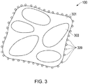
- FIG. 3 shows an illustration of a cross section of an abrasive aggregate 300 comprising a vitreous binder composition 301 having abrasive particles 303 dispersed in the vitreous binder composition, wherein the abrasive particles are diamonds.
- a layer of carbide particles 309, such as silicon carbide particles, is disposed on at least a portion of the outer surface of the aggregate. In certain embodiments, the entire outer surface of the abrasive aggregate is covered with carbide particles.
- FIG. 4 shows a process flow diagram of an embodiment of a method 400 of making an abrasive aggregate.
- Step 402 includes mixing together a plurality of abrasive particles and a vitreous binder composition to form a mixture, wherein the abrasive particles are diamonds.
- Step 406 includes shaping the mixture to form a plurality of abrasive aggregate precursor granules.
- Step 410 includes sintering the abrasive aggregate precursor granules to form a plurality of abrasive aggregates.
- step 402 includes mixing one or more modifier particles together with the abrasive particles and the vitreous binder composition to form the mixture prior to shaping the mixture.
- step 408 includes coating the aggregate precursor granules with carbide particles prior to sintering the aggregate precursor granules.
- step 412 includes classifying the abrasive aggregates after sintering.
- the invention provides an abrasive aggregate as defined by Claim 1.
- the abrasive aggregate can further comprise one or more modifier particles dispersed in the vitreous binder composition.
- the abrasive aggregate can further comprise a layer of carbide particles disposed on at least a portion of the outer surface of the abrasive aggregate.
- the abrasive particles are diamonds.
- the diamonds can be monocrystalline, polycrystalline, or a combination thereof.
- the diamonds can be natural diamonds, synthetic diamonds, metal coated diamonds, resin coated diamonds, or combinations thereof.
- the diamonds can be in a particular size range, conform to a particular size distribution, or a combination thereof. In an embodiment, the diamonds are in a size range of not less than 1 micron and not greater than 2000 microns. In a particular embodiment, the diamonds are in a size range from 100 to 130 microns, such as from 105 to 125 microns.
- the abrasive aggregate can comprise one or more modifier particles.
- the abrasive aggregate does not include modifier particles.
- the abrasive aggregate does include one or more modifier particles.
- the modifier particles can be the same or different.
- the modifier particles are dispersed within the vitreous bond composition along with the abrasive particles and can affect certain physical and abrasive performance properties of the abrasive aggregate.
- the modifier particles can be silicon carbide particles, cerium particles, alumina particles, or a combination thereof.
- the modifier particles can be in a particular size range, conform to a particular size distribution, or a combination thereof.
- the size range of modifying particles can be in a range from 0.1 to 15% of the abrasive particle size.
- the modifier particles are in a size range of not less than 0.5 microns and not greater than 100 microns.
- the modifier particles include silicon carbide particles in a size range of not less than 1 micron and not greater than 100 microns.
- the modifier particles include cerium particles in a size range of not less than 1 micron and not greater than 100 microns.
- the modifier particles include aluminum oxide particles in a size range of not less than 1 micron and not greater than 100 microns.
- the abrasive aggregate includes a vitreous binder composition (also referred to herein as a glass binder composition, glass bond composition, or glass bond).
- the vitreous binder composition is a glass composition that can comprise acidic oxides, amphoteric oxides, alkali oxides, neutral oxides, or a combination thereof.
- Acidic oxides are oxides having the general formula RO or RO2, where R is a metal or transition metal moiety.
- Acidic oxides can include silicon dioxide (silica) (SiO2), manganese (IV) oxide (MnO2), molybdenum trioxide (molybdite) (MoO3), phosphorus pentoxide (P2O5), titanium dioxide (titania) (TiO2), vanadium (V) oxide (V2O5), and zirconium dioxide (ZrO2), or combinations thereof.
- Alkali also known as “basic oxides” or "flux” are oxides having the formula RxO, where R is a metal or transition metal moiety.
- alkali oxides can include cobalt (II) oxide (CoO), copper (II) oxide (cupric oxide)(CuO), nickel (II) oxide (NiO), strontium oxide (strontia) (SrO), magnesium oxide (magnesia) (MgO), calcium oxide (calcia) (CaO), lithium oxide (lithia) (Li2O), barium oxide (baria) (BaO), zinc oxide (calamine)(ZnO), sodium oxide (Na2O), potassium oxide (potash) (K2O), and combinations thereof.
- Amphoteric oxides are oxides having the general formula R2O3, where R is a metal or transition metal moiety.
- amphoteric species can include boron trioxide (boria) (B2O3), chromium (III) oxide (chromia) (Cr2O3), yttrium (III) oxide (yttria) (Y2O3), iron (III) oxide (Fe2O3), and aluminum oxide (alumina) (Al2O3), and combinations thereof.
- the amount of acidic oxides, basic oxides and amphoteric oxides in the vitreous binder composition can vary. In an embodiment, based on the weight of the vitreous binder composition, the vitreous binder composition comprises about 40 wt % to 65 wt% of total combined acid oxides.
- the vitreous binder composition comprises about 15 wt% to 30 wt% of total combined amphoteric oxides. In an embodiment, based on the weight of the vitreous binder composition, the vitreous binder composition comprises about 15 wt% to 25 wt% total combined basic oxides.
- the amount of silicon dioxide can be not less than 40 wt%, such as not less than about 45 wt%, not less than about 50 wt%, or not less than about 55 wt%. In another embodiment, based on the weight of the vitreous binder composition, the amount of silicon dioxide can be not greater than 80 wt%, such as not greater than 75 wt%, not greater than 70 wt%, or not greater than 65 wt%. The amount of silicon dioxide can be within a range comprising any pair of the previous upper and lower limits.
- the amount of silicon dioxide can be in a range of not less than 45 wt% to not greater than 75 wt%, such as 50 wt% to 70 wt%. In a specific embodiment, based on the weight of the vitreous binder composition, the amount of silicon dioxide can be 55 wt% to 60 wt% or 60 wt% to 65 wt%.
- the amount of boron trioxide can be not less than 1 wt%, such as not less than about 2 wt%, not less than about 3 wt%, not less than about 4 wt%, or not less than about 5 wt%. In another embodiment, based on the weight of the vitreous binder composition, the amount of boron trioxide can be not greater than 80 wt%, such as not greater than 75 wt%, not greater than 70 wt%, or not greater than 65 wt%. The amount of boron trioxide can be within a range comprising any pair of the previous upper and lower limits.
- the amount of boron trioxide can be in a range of not less than 45 wt% to not greater than 75 wt%, such as 50 wt% to 70 wt%. In a specific embodiment, based on the weight of the vitreous binder composition, the amount of boron trioxide can be 55 wt% to 60 wt% or 60 wt% to 65 wt%.
- the vitreous binder composition can possess a particular amount of transition metal, which can vary. In an embodiment, based on the weight of the vitreous binder composition, the vitreous binder composition can comprises not less than 1 wt% and not greater than 15 wt% of transition metal.
- the vitreous binder composition can have a particular glass transition temperature, sintering temperature, or combination thereof.
- the vitreous binder composition has a sintering temperature (Ts) in a range of 550°C to 800°C.
- the vitreous binder composition has a glass transition temperature (Tg) in a range of 490°C to 700 °C.
- the composition of the abrasive aggregate's major components can vary within certain ranges.
- the amount of vitreous binder composition that comprises the abrasive aggregate can be varied.
- the vitreous binder composition comprises not less than 1 wt% and not greater than 90 wt% of the weight of the abrasive aggregate, such as not less than 5 wt% and not greater than 85 wt%, or not less than 6 wt% and not greater than 75 wt% of the weight of the abrasive aggregate.
- the amount of abrasive particle comprising the abrasive aggregate can vary.
- the amount of abrasive particles can comprise not less than 15 wt% and not greater than 99 wt% of the weight of the abrasive aggregate.
- the amount of one or more modifier particles in the abrasive aggregates can vary.
- the one or more modifier particles can comprise not less than 0.5 wt% and not greater than 15 wt% of the weight of the abrasive aggregate.
- the amount of abrasive particles comprising the abrasive aggregate can be not less than 10 wt%, such as not less than about 15 wt%, not less than about 20 wt%, not less than about 25 wt%, not less than about 30 wt%, not less than about 40 wt%, or not less than about 45 wt%.
- the amount of abrasive particles comprising the abrasive aggregate can be not greater than 99 wt%, such as not greater than 95 wt%, not greater than 90 wt%, not greater than 85 wt%, not greater than 80 wt%, not greater than 75 wt%, not greater than 70 wt%, or not greater than 65 wt%.
- the amount of abrasive particles can be within a range comprising any pair of the previous upper and lower limits.
- the amount of abrasive particles can be in a range of not less than 10 wt% to not greater than 99 wt%, such as 15 wt% to 95 wt%, or 20 wt% to 90 wt%. In a specific embodiment, the amount of abrasive particles can be 15 wt% to 30 wt%, 45 wt% to 55 wt%, 60 wt% to 70 wt%, or 85 wt% to 90 wt%.
- the amount of vitreous binder composition comprising the abrasive aggregate can be not less than 1 wt%, such as not less than about 3 wt%, not less than about 5 wt%, not less than about 10 wt%, not less than about 15 wt%, not less than about 20 wt%, or not less than about 25 wt%.
- the amount of vitreous binder composition comprising the abrasive aggregate can be not greater than 80 wt%, such as not greater than 75 wt%, not greater than 70 wt%, not greater than 65 wt%, not greater than 60 wt%, not greater than 55 wt%, not greater than 50 wt%, or not greater than 45 wt%.
- the amount of vitreous binder composition can be within a range comprising any pair of the previous upper and lower limits.
- the amount of vitreous binder composition can be in a range of not less than 1 wt% to not greater than 75 wt%, such as 3 wt% to 70 wt%, or 5 wt% to 65 wt%. In a specific embodiment, the amount of vitreous binder composition can be 5 wt% to 15 wt%, 25 wt% to 35 wt%, 45 wt% to 55 wt%, or 65 wt% to 75 wt%.
- the amount of modifier particles comprising the abrasive aggregate can be 0 wt% (i.e., the abrasive aggregate is comprises essentially only abrasive particles and vitreous binder composition). In another embodiment, the amount of modifier particles comprising the abrasive aggregate can be not less than 0.5 wt%, such as not less than about 1 wt%, not less than about 1.5 wt%, not less than about 2 wt%, not less than about 2.5 wt%, or not less than about 3 wt%.
- the amount of modifier particles comprising the abrasive aggregate can be not greater than 15 wt%, such as not greater than 13 wt%, not greater than 10 wt%, not greater than 8 wt%, not greater than 7 wt%, or not greater than 5 wt%.
- the amount of modifier particles can be within a range comprising any pair of the previous upper and lower limits.
- the amount of modifier particles can be in a range of not less than 1 wt% to not greater than 15 wt%, such as 1 wt% to 7 wt%, or 1 wt% to 5 wt%.
- the abrasive aggregate can be in a particular size range, conform to a particular size distribution, or a combination thereof.
- the size range of the abrasive aggregate can be in a range not less than 2 microns, such as not less than 5 microns, not less than 10 microns, not less than 20 microns, not less than 50 microns, not less than 75 microns, not less than 90 microns, not less than 100 microns, not less than 125 microns, not less than 140 microns, or not less than 150 microns.
- the abrasive aggregate can have a size range of not greater than 10,000 microns, such as not greater than 7500 microns, not greater than 5000 microns, not greater than 4000 microns, not greater than 2000 microns, not greater than 1800 microns, not greater than 1500 microns, not greater than 1200 microns, not greater than 1000 microns, not greater than 900 microns, not greater than 800 microns, not greater than 700 microns, or not greater than 600 microns.
- the size of the abrasive aggregate can be within a range comprising any pair of the previous upper and lower limits. In a particular embodiment, the size of the abrasive aggregate can be in a range of not less than 2 microns to not greater than 4000 microns.
- At least a portion of the outer surface of the abrasive aggregate can be covered with outer layer particles, such as carbide particles, alumina particles, or a combination thereof. In an embodiment, no portion of the abrasive aggregate is covered with a outer layer of carbide particles or alumina particles. In another embodiment, at least a portion of the outer surface of the abrasive aggregate can be covered with carbide particles, alumina particles, or a combination thereof. The amount of the surface of the aggregate that is covered with carbide particles, alumina particles, or a combination thereof can vary. In an embodiment, the portion of the outer surface of the abrasive aggregate that is covered with the particles is not less than 5% and not more than 100% of the outer surface of the abrasive aggregate.
- the particles of the outer layer can vary in size.
- the outer layer particles can be in a size range of not less than 1 micron and not greater than 100 microns.
- the size of the outer layer particles can have a certain relationship with respect to the size of the abrasive aggregate.
- the size of the outer layer particles are in a particular ratio range with the size of the abrasive aggregate (Size outer layer :Size Aggregate ).
- the ratio of the size of the outer layer particles to the abrasive aggregate is in a range of 1:500 to 1:20.
- the carbide particles can include boron carbide, silicon carbide, tungsten carbide, and combinations thereof. In an embodiment, the carbide particles are silicon carbide particles.
- the abrasive aggregates can possess beneficial and characteristic properties.
- the abrasive aggregates can have a beneficial loose packed density in a particular range.
- the abrasive aggregates have a loose packed density in a range of not less than 0.5 g/cm3 to not greater than 3.5 g/cm3.
- the abrasive aggregates have a loose packed density in a range of not less than 2.75 g/cm3 to not less than 3.0 g/cm3.
- the abrasive aggregate can have a beneficial porosity in a particular range.
- the abrasive aggregates have a porosity in a range of 5% to 85% as measured by mercury porosimetry.
- the abrasive aggregate can have a beneficial crush strength (represented by a crush%) in a particular range.
- the abrasive aggregates have a crush% value of not greater than 90%, such as not greater than 85%, not greater than 80%, not greater than 75%, not greater than 70%, not greater than 65%, not greater than 60%, not greater than 55%, not greater than 50%, not greater than 45%, not greater than 40%, or not even greater than 35%, wherein the crush% is measured at a load of 5 MPa.
- the crush strength can be measured at a particular sieve mesh size, such as (-35 / +45), or -40/+60), or the like.
- the aggregate can be made by providing an aggregate forming mixture, processing the aggregate forming mixture into an aggregate precursor, and processing the aggregate precursor into the aggregate.
- step 402 includes mixing together a plurality of abrasive particles and a vitreous binder composition to form a mixture, wherein the abrasive particles are diamonds.
- This activity can be accomplished by combining one or more glass frit powders that contain the desired combination of oxides with diamonds.
- the mixing can be done wet (aqueous) or dry.
- the mixing is performed with the aid of an aqueous solution of polyethylene glycol, which acts as a temporary organic binder that allows the glass powder and diamond mixture to be shaped.
- Other organic temporary binders are known in the art.
- modifier particles can be added to the mixture of vitreous binder composition and diamonds.
- Adequate mixing of the vitreous binder composition can be accomplished by any known suitable methods.
- the ingredients are mixed together using a mortar and pestle until uniform.
- the ingredients are mixed together using an automated tumbler until uniform.
- the ingredients are combined in an automated grinder mixer until uniform.
- Step 406 includes shaping the mixture to form a plurality of abrasive aggregate precursor granules.
- Shaping of the mixture to form a plurality of abrasive aggregate precursor granules may be accomplished by any means suitable for shaping a wet mixture into granules, including shaping by screening, pressing, sieving, extruding, segmenting, casting, stamping, cutting, or a combination thereof.
- the wet mixture may be shaped into the abrasive aggregate precursor granules by pushing, or otherwise moving, the wet mixture through a sieve or screen.
- An additional optional activity is drying the plurality of aggregate precursor granules. Drying can be performed at temperatures below the expected curing temperature, such as at ambient temperature, to remove water from the mixture but leave the aggregate precursor granules unsintered. Dried aggregate precursor granules can be stored for later usage. The dried aggregate precursor granules can then be sintered prior to being used or incorporated into a fixed abrasive article. In an embodiment, drying the plurality of shaped aggregate precursor granules is performed.
- Step 410 includes sintering the abrasive aggregate precursor granules to form a plurality of abrasive aggregates.
- Sintering of the aggregate precursor granules can be accomplished by any known suitable methods. Sintering can be done under pressure or at ambient pressure. The sintering atmosphere can be a reducing atmosphere if desired.
- the aggregate precursor granules are fired with graphite powder to prevent oxidation. The heat can be ramped up in intervals, followed by a heat soak at a desired temperature or temperatures for a desired period of time, followed by a cool down period.
- the sintering is accomplished by ramping up the temperature until a desired sintering temperature in a range of 600°C to 800°C is reached, the granules are soaked at that temperature for about 1 to 5 hours and then allowed to cool down.
- the precursor granules are disposed on a graphite sheet during the sintering process.
- Step 408 is performed prior to sintering, and coating the precursor granules with a layer of carbide particles occurs.
- Applying the coating of carbide particles to the surface of the abrasive precursor granules can be accomplished placing the surface of the precursor granules in contact with the carbide particles. Suitable methods include, pouring the carbide particles onto the surface of the precursor granules, or placing the precursor granules in a container with a sufficient amount of carbide particles to cover a desired amount of surface area of the precursor granules.
- the amount of carbide particles used to coat a portion of the precursor granules equal to 0.5 to 4 times the weight of the precursor granules. Put another way, the ratio of the weight of the carbide particles to precursor granules is in a range from 0.5:1 to 4:1.
- At least a portion of the precursor granule can be covered with a layer of oxide particles to improve the yield of the abrasive aggregates.
- Oxide particles can include alumina particles.
- at least a portion of the precursor granule is covered with alumina particles.
- at least a portion of the precursor granule is covered with particles comprising carbide particles, oxide particles, or a combination thereof.
- the sintered, completed abrasive aggregates can be classified according to size prior to being used as a loose abrasive or being incorporated into a fixed abrasive, such as a coated abrasive, nonwoven abrasive, or bonded abrasive.
- Completed abrasive aggregates can be used as loose abrasives (e.g., in an abrasive slurry or as blast media) or incorporated into fixed abrasives.
- Fixed abrasives include bonded abrasives, coated abrasives, nonwoven abrasives, engineered abrasives (also called structured abrasives), and combinations thereof.
- completed abrasive aggregates can be incorporated into bonded abrasive wheels, nonwoven abrasive wheels, coated abrasive discs, coated abrasive belts, coated abrasive sheets, coated abrasive films, or a combination thereof.
- fixed abrasive articles include lofty open nonwoven abrasive articles (e.g., webs and sheets), unified (also called “unitized” in the art) abrasive wheels, and convolute abrasive wheels, that can be manufactured through processes that include common steps known in the art such as: coating a curable composition, typically in slurry form, on a nonwoven fiber web.
- the curable composition can comprise polymeric prepolymer; a curative; and optionally additives.
- the nonwoven fiber web is typically compressed (i.e., densified).
- Nonwoven fiber webs suitable for use in the aforementioned abrasive articles are well known in the abrasives art.
- the nonwoven fiber web comprises an entangled web of fibers.
- the fibers may comprise continuous fiber, staple fiber, or a combination thereof.
- the fiber web may be made air laid, carded, stitch bonded, spun bonded, wet laid, hydroentanglement, and/or melt blown procedures.
- Nonwoven fiber webs are typically selected to be suitably compatible with adhering binders and abrasive particles while also being processable in combination with other components of the article, and typically can withstand processing conditions (e.g., temperatures) such as those employed during application and curing of the curable composition.
- the fibers may be chosen to affect properties of the abrasive article such as, for example, flexibility, elasticity, durability or longevity, abrasiveness, and finishing properties. Examples of fibers that may be suitable include natural fibers, synthetic fibers, and mixtures of natural and/or synthetic fibers.
- the fiber may be homogenous or a composite such as a bicomponent fiber (e.g., a co-spun sheath-core fiber).
- the fibers may be tensilized and crimped, but may also be continuous filaments such as those formed by an extrusion process. Combinations and blends of fibers may also be used.
- the nonwoven fiber web Prior to impregnation with the curable composition, the nonwoven fiber web typically has a specific weight per unit area (i.e., basis weight) and thickness. Frequently, as known in the art, it is useful to apply a pre-bond resin to the nonwoven fiber web prior to coating with the curable composition.
- the pre-bond resin serves, for example, to help maintain the nonwoven fiber web integrity during handling, and may also facilitate bonding of the binder composition to the nonwoven fiber web.
- Suitable prebond resins can include phenolic resins, urethane resins, hide glue, acrylic resins, urea-formaldehyde resins, melamine-formaldehyde resins, epoxy resins, and combinations thereof.
- the amount of pre-bond resin is typically adjusted toward the minimum amount consistent with bonding the fibers together at their points of crossing contact.
- the nonwoven fiber web can include thermally bondable fibers, and thermal bonding of the nonwoven fiber web can be helpful to maintain web integrity during processing.
- the curable composition can be mixed with and/or include one or more additives.
- Additives can include fillers, plasticizers, surfactants, lubricants, colorants (e.g., pigments), bactericides, fungicides, grinding aids, and antistatic agents.
- a nonwoven abrasive web is prepared by adhering inventive abrasive aggregates as described herein to a nonwoven web with a curable binder.
- the coating weight for the abrasive aggregates can depend on the particular binder used, the process for applying the abrasive aggregates, and the size of the abrasive aggregates.
- Binders useful for adhering the abrasive aggregates to the nonwoven fiber web are known in the art and can be selected according to the final product requirements.
- Typical binders can include those comprising polyurethane, phenolic, acrylate, and combinations thereof.
- the abrasive article is a nonwoven abrasive article comprising: a nonwoven web; a binder disposed on (and/or throughout) the nonwoven web, and abrasive aggregates as described herein disposed on the binder.
- temperatures are expressed in degrees Celsius
- pressure is ambient
- concentrations are expressed in weight percentages.
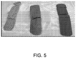
- Samples 1-3 were prepared according to the following method: All ingredients except for diamonds the organic binder were mixed in a beaker with a spoon and then screened with a mesh 140 sieve. The diamonds were added and then the organic binder was spoon-mixed in to achieve a uniform wet mixture. The wet mixture was then hand pushed through mesh 20 sieve to form wet aggregate precursor granules. The wet precursor granules were dried, then screened with a mesh 20 sieve, and then fired in the presence of graphite powder to prevent oxidation. The firing profile was ramp 300°C/hr., soak at 550°C for 1 hr., then 690°C for 4 hr., then cool.
- the fired aggregates for each sample composition (S1-S3) melted together to form bars, as shown in FIG. 5 from left to right respectively. It is notable that the fired bars shown in Figure 5 had various shades of gray color due to the various concentrations of diamond grain. Because the diamonds have a black color, the color of the bars darkens as the diamond concentration increases. Therefore, S 1, with about 25 wt% diamond, had the lightest gray color, S2, with about 48 wt% diamond, had the middle gray color, and S3, with about 64 wt% diamond, had the darkest gray color.
- the fired bars were then crushed and sieved to collect abrasive aggregates having a size between mesh 25 and 80.
- the fired S1-S3 aggregates contained about 1-5 wt% SiC as a modifier, which functioned as pore inducer.
- S1 also contained about 5 wt% of 5 ⁇ m cerium particles, which created extra porosity in the fired aggregates. Measured properties of the fired aggregates are provided below in Table 2. Note that loose pack density increased with increasing diamond concentration and the addition of cerium appears to contribute to an increase in porosity.
- samples are subjected to crush% testing as follows. Aggregate samples were screened at or between a particular mesh size (e.g., between mesh 35 and 45); and a fixed amount of each sample (e.g., 5 grams) was placed in a one inch die. The die was then subjected to a pressure of 5 MPa. The collected aggregate was again screened and the amount that passed through the mesh screens was collected and recorded. The higher the percentage of material that passed through the screen(s), the greater the amount of material that was crushed, thus indicating a weaker aggregate.
- a particular mesh size e.g., between mesh 35 and 45
- a fixed amount of each sample e.g., 5 grams
- the fired aggregate is poured through a funnel in a 100 cc cup. Any excess material is removed with a blade and the cup is weighed. The loose pack density is equal to the weight divided by the cup volume.
- FIG. 6A and FIG. 6B for S1
- FIG. 7A and FIG. 7B for S2
- FIG. 8A and FIG. 8B for S3.
- Samples 4 and 5 were prepared the same as S3, above in Example 1, except that SiC was not used in S4 and S5, and a different glass bond (glass bond B instead of glass bond A) was used for S5.
- Glass bond A and glass bond B compare as follows:
- S4 and S5 were prepared using the materials and amounts listed in Table 3.
- Table 3 Abrasive Aggregates S4-S5 S4 wt% Wet S4 wt% Dry S4 wt% Fired S5 wt% Wet S5 wt% Dry S5 wt% Fired Glass Bond A 30.2 32.2 33.3 - - - Glass Bond B - - - 30.2 32.2 33.3 Diamonds 60.4 64.5 66.7 60.4 64.5 66.7 Organic Binder 9.3 3.3 0 9.3 3.3 0 Cerium - - - - - - SiC - - - - - - - - - - - - - -
- S4 and S5 were prepared according to the same method as S3 above in Example 1, except that, for S4 and S5, a mesh 60 sieve was used to break up lumps in the mixed dry ingredients, and the firing profile was changed to: ramp 180°C/hr., soak at 750°C for 1hr, then cool.
- FIG. 9 shows an SEM image of the fired aggregates of S4.
- FIG. 10 shows an SEM image of the fired aggregates of S5.
- the S4 and S5 aggregates both appeared to have the same surface morphology; however, crush testing at 5 MPa of the fired aggregates having a size cut of mesh 35/45 showed that the S4 aggregate had a 76% crush strength and the S5 aggregate was weaker with a 90% crush strength.
- Table 4 Properties of S4-S5 Fired Aggregates Sample wt% Glass Bond Aggregate Size Cut Loose Pack Density (g/cm3) Crush % Comments S4 33.3 mesh 35/45 - 76 glass bond A S5 33.3 mesh 35/40 - 90 glass bond B
- Sample 6 was prepared the same as S1 above in Example 1, except that S6 includes significantly less glass bond than S1.
- S6 was prepared using the materials and amounts listed in Table 5.
- Table 5 Abrasive Aggregates S6 S6 wt% Wet S6 wt% Dry S6 wt% Fired Glass Bond A 33.8 36.8 38.5 Diamonds 54.1 58.8 61.5 Organic Binder 12.2 4.4 0 Cerium - - - SiC - - -
- the method for making Sample 6 is as follows. First, the glass bond and the diamond grain were mixed in an automated mixer for 5 minutes. Under agitation, the organic binder was added to achieve a consistent wet mixture. Wet precursor granules were formed with a Quadro Comil using a mesh 7C032 screen (0.81mm, equivalent to mesh 20). The remaining wet mixture was hand pushed through a mesh 20 screen to produce additional wet precursor granules. The wet precursor granules were then dried, screened with mesh 20, and fired with a layer of graphite using the following firing profile: ramp 180°C/hr., soak at 750°C for 1 hr., and cool down. The precursor granules melted together to forma fired block, which was then crushed and sieved to collect fired aggregates between size mesh 25 and mesh 80.
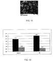
- FIG 11 is an SEM image of the produced fired aggregates for S6.
- Table 6 Properties of S6 Fired Aggregates Sample wt% Glass Bond Aggregate Size Cut Loose Pack Density (g/cm3) Crush % (35/45) @ 5 MPa Comments S6 38.5 Mesh 25/80 1.18 68 Glass Bond A
- Sample 7 was made using the materials and amounts listed in Table 8.
- Table 8 Abrasive Aggregates S7 S7 wt% Wet S7 wt% Dry S7 wt% Fired Glass Bond A 56.82 63.92 68.18 Diamonds 20.83 23.44 25 OrganicB binder 16.67 6.25 0 Alumina 5.68 6.39 6.82 SiC - - -
- Sample 7 was prepared according to the following method: All the ingredients except for the glass bond and organic binder were weighed into a jar and mixed with an automated tumbler for 30 minutes. The glass bond and organic binder were then mixed with the other ingredients to form a uniform wet mixture. The wet mixture was screened with mesh 30 and the formed precursor granules were dried in an oven at 350°F for 1 hour and then air dried for 8-12 hours.
- FIG. 13A and FIG. 13B are SEM images of the fired aggregates of S7.
- inventive abrasive discs were used to make inventive abrasive discs.
- inventive abrasive discs were compared to conventional (control) diamond cloth abrasive discs.
- the inventive discs had a useful life than was approximately twice as long as the control discs.
- the inventive discs had a higher cumulative cut rate that varied from about 15% to 30% higher than the cut rate for the control discs.
- Samples 8 was prepared according to the following method using the dry and fired aggregate having the composition described below in Table 10.
- Table 10 Abrasive Aggregates S8 S8 wt% Dry S8 wt% Fired Glass Bond A 33.1 33.1 Diamonds 63.6 63.6 SiC 3.3 3.3
- S9-S11 were prepared using the dry S8 precursor granules according to the following method: For each sample S9-S11, 100 grams of the dry S8 precursor granules were mixed with a specific amount of SiC powder (size J2500, 5 micron) to form a mixture of dry granules and SiC powder. For Sample S9, the 100 grams dry green aggregates were mixed with 50 grams of SiC J2500. For Sample S10, the 100 grams of dry precursor granules were mixed with 66 grams of SiC powder (J2500, 5 micron). For Sample 11, the 100 grams of dry precursor granules were mixed with 100 grams of SiC powder (J2500, 5 micron).
- the mixtures of SiC coated precursor granules were each loaded into a sagger (bed depth less than 3/8 inches) and fired at 750°C for about 1 hour.
- the fired abrasive aggregate was collected between mesh 30 and 80 (0.18 to 0.6 mm).
- Sample 12 was prepared using the materials and amounts listed in Table 12.
- Table 12 Abrasive Aggregates S12 S12 wt% Wet S12 wt% Dry S12 wt% Fired Glass Bond A 9.22 9.72 10 Diamonds 82.95 87.52 90 Organic Binder 7.83 2.75 0 Alumina - - - SiC - - -
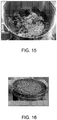
- S12 was prepared according to the following method: All of the materials listed in Table 12 were added to a beaker, except for the organic binder, and were hand mixed with a spatula until a substantially uniform consistency was reached. The organic binder was then added to form a wet mixture and the wet mixture was added to an automated grinder (Strand Grinder) as shown in FIGs. 15 . The wet mixture was mixed for 5 seconds, stopped to scrape the walls, and repeated 4 times. The wet mixture was then screened with mesh 20 screen to form precursor granules as shown in FIG. 16 .
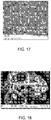
- FIG. 17 shows an SEM image of the fired aggregates of S12.
- Control abrasive nonwoven and inventive nonwoven abrasive wheels were prepared and were used to conduct abrasive testing ("90 Degree Angle Testing") according to the conditions listed below.
- the control wheels included conventional loose diamond grit size 120/140.
- the inventive nonwoven wheels included the S12 aggregates.
- An inventive S12 wheel and the 90 Degree Angle Testing set-up are shown in FIG. 20 .
- the 90 Degree Angle Testing results are listed in Table 14.
- Table 14: Flat Surface Testing Results ID Grain Shed Cut Grind ratio Comparison to Avg. Control Cut Comparison to Avg. Control Grind Ratio D52 Control. 1 0.93 2.82 3.03 0.97 1.03 D52 Control. 2 0.99 2.96 2.99 1.02 1.02 D52 Control 3 0.97 2.87 2.96 0.99 1.01 D52 Control 4 1.07 2.96 2.77 1.02 0.94 Avg. Control 0.99 2.90 2.94 1.00 1.00 DA1 Inv. 1 2.17 4.81 2.22 1.66 0.75 DA1 Inv. 2 2.01 4.52 2.25 1.56 0.77 DA1 Inv. 3 2.97 4.78 1.61 1.65 0.55 DA1 Inv. 4 2.23 4.73 2.12 1.63 0.72 Avg. Inv. 2.35
- the inventive wheels produced a higher cumulative cut than the control wheels.
- the inventive wheels did have a higher shed rate than the control wheels; however, the average grind ratio (mass removed from workpiece/mass shed from wheel) of the inventive wheels was surprisingly only about 30% lower than the average for the control wheels but was surprisingly able to achieve an average cumulative cut that was 62% higher than the average for the control wheels.
- Such an increased cumulative cut is particularly beneficial and significant for particular hard workpiece surfaces, such as tungsten carbide, as was used in the testing.
Description
- The present disclosure relates to abrasive aggregates of diamond with a vitrified bond, and methods of making and using such abrasive aggregates, including in abrasive articles.
- Abrasive tools can use an abrasive to shape or finish a workpiece by wearing away, such as through rubbing or grinding, a portion of the material forming the workpiece. The abrasive can include abrasive grains contained within a bond material. The abrasive grains can include superabrasive grains (e.g., diamond) to provide superior grinding performance on a variety of materials. There exists a need for an improved abrasive or abrasive tool including superabrasive grains.
- Document
US-A-2002/0151265 reveals an abrasive aggregate comprising a vitreous binder matrix and diamond abrasive particles dispersed in the vitreous binder matrix. - Abrasive products, such as coated abrasives, bonded abrasives, nonwoven abrasives and loose abrasives are used in various industries to abrade work pieces, such as by lapping, grinding, or polishing. Surface processing using abrasive products spans a wide industrial scope from initial coarse material removal to high precision finishing and polishing of surfaces at a submicron level. Effective and efficient surface processing of extremely hard surfaces, such as metal surfaces, ceramic surfaces, and cermet hybrid surfaces poses numerous challenges, including how to achieve high material removal rates. Therefore, the industry continues to demand further improved abrasive products.
- Embodiments are illustrated by way of example and are not limited in the accompanying figures.
-
FIG. 1 is an illustration of an embodiment of an abrasive aggregate comprising diamond abrasive particles and a vitreous binder composition. -
FIG. 2 is an illustration of an embodiment of an abrasive aggregate comprising diamond abrasive particles, modifier particles, pores, and a vitreous binder composition. -
FIG. 3 is an illustration of an embodiment of an abrasive aggregate comprising diamond abrasive particles, a vitreous bond, and a layer of silicon carbide particles disposed on the outer surface of the abrasive aggregate. -
FIG. 4 is a process flow diagram of an embodiment of a method of making an abrasive aggregate. -
FIG. 5 is a photograph of bars of abrasive aggregate material formed according to an embodiment. -
FIG. 6A is an image of abrasive aggregates according to an embodiment. -
FIG. 6B is a cross section image of the abrasive aggregates shown inFIG. 6A . -
FIG. 7A is an image of abrasive aggregates according to an embodiment. -
FIG. 7B is a cross section image of the abrasive aggregates shown inFIG. 7A . -
FIG. 8A is an image of abrasive aggregates according to an embodiment. -
FIG. 8B is a cross section image of the abrasive aggregates shown inFIG. 8A . -
FIG. 9 is an image of abrasive aggregates according to an embodiment. -
FIG. 10 is an image of abrasive aggregates according to an embodiment. -
FIG. 11 is an image of abrasive aggregates according to an embodiment. -
FIG. 12 is a graph comparing abrasive performance of a nonwoven wheel that includes inventive abrasive aggregates according to an embodiment to abrasive performance of nonwoven wheels that include conventional diamonds. -
FIG. 13A is an image of abrasive aggregates according to an embodiment. -
FIG. 13B is a cross section image of the abrasive aggregates shown inFIG. 13A . -
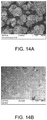
FIG. 14A is an image of abrasive aggregates according to an embodiment. -
FIG. 14B is a cross section image of the abrasive aggregates shown inFIG. 14A . -
FIG. 15 is an image of a mixture according to an embodiment of abrasive particles, vitreous binder composition, and aqueous organic binder. -
FIG. 16 is an image of abrasive aggregate precursor granules according to an embodiment formed from the mixture shown inFIG. 15 . -
FIG. 17 is an image of abrasive aggregates according to an embodiment formed from the abrasive aggregate precursor granules shown inFIG. 16 . -
FIG. 18 is a cross section image of the abrasive aggregates shown inFIG. 17 . -
FIG. 19 is a graph comparing abrasive performance of conventional nonwoven grinding wheels that include loose diamond to inventive nonwoven grinding wheels that include abrasive aggregates embodiments shown inFIG. 17 . -
FIG. 20 is a photograph showing an inventive nonwoven abrasive wheel set up to conduct 90 Degree Angle testing that includes the inventive abrasive aggregates shown inFIG. 17 . - Skilled artisans appreciate that elements in the figures are illustrated for simplicity and clarity and have not necessarily been drawn to scale. For example, the dimensions of some of the elements in the figures may be exaggerated relative to other elements to help to improve understanding of embodiments of the invention.
- As used herein, the term "aggregate" may be used to refer to a particle made of a plurality of smaller particles that have been combined in such a manner that it is relatively difficult to separate or disintegrate the aggregate particle into smaller particles by the application of pressure or agitation. This is in contrast to the term "agglomerate," which is used herein to refer to a particle made up of a plurality of smaller particles that have been combined in such a manner that it is relatively easy to separate the agglomerate particle or disintegrate the agglomerate particle back into smaller particles, such as by the application of pressure or hand agitation.
-
FIG. 1 shows an illustration of a cross section of anabrasive aggregate 100 comprising avitreous binder composition 101 andabrasive particles 103 dispersed in the vitreous binder composition, wherein the abrasive particles are diamonds. -
FIG. 2 shows an illustration of a cross section of anabrasive aggregate 200 comprising avitreous binder composition 201 havingabrasive particles 203,modifier particles 205, andpores 207 dispersed in the vitreous binder composition, wherein the abrasive particles are diamonds. -
FIG. 3 shows an illustration of a cross section of an abrasive aggregate 300 comprising avitreous binder composition 301 havingabrasive particles 303 dispersed in the vitreous binder composition, wherein the abrasive particles are diamonds. A layer ofcarbide particles 309, such as silicon carbide particles, is disposed on at least a portion of the outer surface of the aggregate. In certain embodiments, the entire outer surface of the abrasive aggregate is covered with carbide particles. -
FIG. 4 shows a process flow diagram of an embodiment of amethod 400 of making an abrasive aggregate.Step 402 includes mixing together a plurality of abrasive particles and a vitreous binder composition to form a mixture, wherein the abrasive particles are diamonds. Step 406 includes shaping the mixture to form a plurality of abrasive aggregate precursor granules. Step 410 includes sintering the abrasive aggregate precursor granules to form a plurality of abrasive aggregates. Optionally,step 402 includes mixing one or more modifier particles together with the abrasive particles and the vitreous binder composition to form the mixture prior to shaping the mixture. Optionally,step 408 includes coating the aggregate precursor granules with carbide particles prior to sintering the aggregate precursor granules. Optionally,step 412 includes classifying the abrasive aggregates after sintering. - The invention provides an abrasive aggregate as defined by Claim 1. In an embodiment, the abrasive aggregate can further comprise one or more modifier particles dispersed in the vitreous binder composition. In another embodiment, the abrasive aggregate can further comprise a layer of carbide particles disposed on at least a portion of the outer surface of the abrasive aggregate.
- The abrasive particles are diamonds. The diamonds can be monocrystalline, polycrystalline, or a combination thereof. The diamonds can be natural diamonds, synthetic diamonds, metal coated diamonds, resin coated diamonds, or combinations thereof. The diamonds can be in a particular size range, conform to a particular size distribution, or a combination thereof. In an embodiment, the diamonds are in a size range of not less than 1 micron and not greater than 2000 microns. In a particular embodiment, the diamonds are in a size range from 100 to 130 microns, such as from 105 to 125 microns.
- If desired, the abrasive aggregate can comprise one or more modifier particles. In a particular embodiment, the abrasive aggregate does not include modifier particles. In another embodiment, the abrasive aggregate does include one or more modifier particles. The modifier particles can be the same or different. When included, the modifier particles are dispersed within the vitreous bond composition along with the abrasive particles and can affect certain physical and abrasive performance properties of the abrasive aggregate. In an embodiment, the modifier particles can be silicon carbide particles, cerium particles, alumina particles, or a combination thereof. The modifier particles can be in a particular size range, conform to a particular size distribution, or a combination thereof. In an embodiment, the size range of modifying particles can be in a range from 0.1 to 15% of the abrasive particle size. In an embodiment, the modifier particles are in a size range of not less than 0.5 microns and not greater than 100 microns. In an embodiment, the modifier particles include silicon carbide particles in a size range of not less than 1 micron and not greater than 100 microns. In another embodiment, the modifier particles include cerium particles in a size range of not less than 1 micron and not greater than 100 microns. In another embodiment, the modifier particles include aluminum oxide particles in a size range of not less than 1 micron and not greater than 100 microns.
- The abrasive aggregate includes a vitreous binder composition (also referred to herein as a glass binder composition, glass bond composition, or glass bond). The vitreous binder composition is a glass composition that can comprise acidic oxides, amphoteric oxides, alkali oxides, neutral oxides, or a combination thereof. Acidic oxides are oxides having the general formula RO or RO2, where R is a metal or transition metal moiety. Acidic oxides can include silicon dioxide (silica) (SiO2), manganese (IV) oxide (MnO2), molybdenum trioxide (molybdite) (MoO3), phosphorus pentoxide (P2O5), titanium dioxide (titania) (TiO2), vanadium (V) oxide (V2O5), and zirconium dioxide (ZrO2), or combinations thereof. Alkali (also known as "basic oxides" or "flux") are oxides having the formula RxO, where R is a metal or transition metal moiety. In an embodiment, alkali oxides can include cobalt (II) oxide (CoO), copper (II) oxide (cupric oxide)(CuO), nickel (II) oxide (NiO), strontium oxide (strontia) (SrO), magnesium oxide (magnesia) (MgO), calcium oxide (calcia) (CaO), lithium oxide (lithia) (Li2O), barium oxide (baria) (BaO), zinc oxide (calamine)(ZnO), sodium oxide (Na2O), potassium oxide (potash) (K2O), and combinations thereof. Amphoteric oxides are oxides having the general formula R2O3, where R is a metal or transition metal moiety. In an embodiment, amphoteric species can include boron trioxide (boria) (B2O3), chromium (III) oxide (chromia) (Cr2O3), yttrium (III) oxide (yttria) (Y2O3), iron (III) oxide (Fe2O3), and aluminum oxide (alumina) (Al2O3), and combinations thereof. The amount of acidic oxides, basic oxides and amphoteric oxides in the vitreous binder composition can vary. In an embodiment, based on the weight of the vitreous binder composition, the vitreous binder composition comprises about 40 wt % to 65 wt% of total combined acid oxides. In an embodiment, based on the weight of the vitreous binder composition, the vitreous binder composition comprises about 15 wt% to 30 wt% of total combined amphoteric oxides. In an embodiment, based on the weight of the vitreous binder composition, the vitreous binder composition comprises about 15 wt% to 25 wt% total combined basic oxides.
- In an embodiment, based on the weight of the vitreous binder composition, the amount of silicon dioxide can be not less than 40 wt%, such as not less than about 45 wt%, not less than about 50 wt%, or not less than about 55 wt%. In another embodiment, based on the weight of the vitreous binder composition, the amount of silicon dioxide can be not greater than 80 wt%, such as not greater than 75 wt%, not greater than 70 wt%, or not greater than 65 wt%. The amount of silicon dioxide can be within a range comprising any pair of the previous upper and lower limits. In a particular embodiment, based on the weight of the vitreous binder composition, the amount of silicon dioxide can be in a range of not less than 45 wt% to not greater than 75 wt%, such as 50 wt% to 70 wt%. In a specific embodiment, based on the weight of the vitreous binder composition, the amount of silicon dioxide can be 55 wt% to 60 wt% or 60 wt% to 65 wt%.
- In an embodiment, based on the weight of the vitreous binder composition, the amount of boron trioxide can be not less than 1 wt%, such as not less than about 2 wt%, not less than about 3 wt%, not less than about 4 wt%, or not less than about 5 wt%. In another embodiment, based on the weight of the vitreous binder composition, the amount of boron trioxide can be not greater than 80 wt%, such as not greater than 75 wt%, not greater than 70 wt%, or not greater than 65 wt%. The amount of boron trioxide can be within a range comprising any pair of the previous upper and lower limits. In a particular embodiment, based on the weight of the vitreous binder composition, the amount of boron trioxide can be in a range of not less than 45 wt% to not greater than 75 wt%, such as 50 wt% to 70 wt%. In a specific embodiment, based on the weight of the vitreous binder composition, the amount of boron trioxide can be 55 wt% to 60 wt% or 60 wt% to 65 wt%.
- The vitreous binder composition can possess a particular amount of transition metal, which can vary. In an embodiment, based on the weight of the vitreous binder composition, the vitreous binder composition can comprises not less than 1 wt% and not greater than 15 wt% of transition metal.
- The vitreous binder composition can have a particular glass transition temperature, sintering temperature, or combination thereof. In an embodiment, the vitreous binder composition has a sintering temperature (Ts) in a range of 550°C to 800°C. In an embodiment, the vitreous binder composition has a glass transition temperature (Tg) in a range of 490°C to 700 °C.
- The composition of the abrasive aggregate's major components (i.e., vitreous binder composition, abrasive particles, and modifier particles) can vary within certain ranges. The amount of vitreous binder composition that comprises the abrasive aggregate can be varied. In an embodiment, the vitreous binder composition comprises not less than 1 wt% and not greater than 90 wt% of the weight of the abrasive aggregate, such as not less than 5 wt% and not greater than 85 wt%, or not less than 6 wt% and not greater than 75 wt% of the weight of the abrasive aggregate. The amount of abrasive particle comprising the abrasive aggregate can vary. In an embodiment, the amount of abrasive particles can comprise not less than 15 wt% and not greater than 99 wt% of the weight of the abrasive aggregate. The amount of one or more modifier particles in the abrasive aggregates can vary. The one or more modifier particles can comprise not less than 0.5 wt% and not greater than 15 wt% of the weight of the abrasive aggregate.
- In an embodiment, the amount of abrasive particles comprising the abrasive aggregate can be not less than 10 wt%, such as not less than about 15 wt%, not less than about 20 wt%, not less than about 25 wt%, not less than about 30 wt%, not less than about 40 wt%, or not less than about 45 wt%. In another embodiment, the amount of abrasive particles comprising the abrasive aggregate can be not greater than 99 wt%, such as not greater than 95 wt%, not greater than 90 wt%, not greater than 85 wt%, not greater than 80 wt%, not greater than 75 wt%, not greater than 70 wt%, or not greater than 65 wt%. The amount of abrasive particles can be within a range comprising any pair of the previous upper and lower limits. In a particular embodiment, the amount of abrasive particles can be in a range of not less than 10 wt% to not greater than 99 wt%, such as 15 wt% to 95 wt%, or 20 wt% to 90 wt%. In a specific embodiment, the amount of abrasive particles can be 15 wt% to 30 wt%, 45 wt% to 55 wt%, 60 wt% to 70 wt%, or 85 wt% to 90 wt%.
- In an embodiment, the amount of vitreous binder composition comprising the abrasive aggregate can be not less than 1 wt%, such as not less than about 3 wt%, not less than about 5 wt%, not less than about 10 wt%, not less than about 15 wt%, not less than about 20 wt%, or not less than about 25 wt%. In another embodiment, the amount of vitreous binder composition comprising the abrasive aggregate can be not greater than 80 wt%, such as not greater than 75 wt%, not greater than 70 wt%, not greater than 65 wt%, not greater than 60 wt%, not greater than 55 wt%, not greater than 50 wt%, or not greater than 45 wt%. The amount of vitreous binder composition can be within a range comprising any pair of the previous upper and lower limits. In a particular embodiment, the amount of vitreous binder composition can be in a range of not less than 1 wt% to not greater than 75 wt%, such as 3 wt% to 70 wt%, or 5 wt% to 65 wt%. In a specific embodiment, the amount of vitreous binder composition can be 5 wt% to 15 wt%, 25 wt% to 35 wt%, 45 wt% to 55 wt%, or 65 wt% to 75 wt%.
- In an embodiment, the amount of modifier particles comprising the abrasive aggregate can be 0 wt% (i.e., the abrasive aggregate is comprises essentially only abrasive particles and vitreous binder composition). In another embodiment, the amount of modifier particles comprising the abrasive aggregate can be not less than 0.5 wt%, such as not less than about 1 wt%, not less than about 1.5 wt%, not less than about 2 wt%, not less than about 2.5 wt%, or not less than about 3 wt%. In another embodiment, the amount of modifier particles comprising the abrasive aggregate can be not greater than 15 wt%, such as not greater than 13 wt%, not greater than 10 wt%, not greater than 8 wt%, not greater than 7 wt%, or not greater than 5 wt%. The amount of modifier particles can be within a range comprising any pair of the previous upper and lower limits. In a particular embodiment, the amount of modifier particles can be in a range of not less than 1 wt% to not greater than 15 wt%, such as 1 wt% to 7 wt%, or 1 wt% to 5 wt%.
- The abrasive aggregate can be in a particular size range, conform to a particular size distribution, or a combination thereof. In an embodiment, the size range of the abrasive aggregate can be in a range not less than 2 microns, such as not less than 5 microns, not less than 10 microns, not less than 20 microns, not less than 50 microns, not less than 75 microns, not less than 90 microns, not less than 100 microns, not less than 125 microns, not less than 140 microns, or not less than 150 microns. In an embodiment, the abrasive aggregate can have a size range of not greater than 10,000 microns, such as not greater than 7500 microns, not greater than 5000 microns, not greater than 4000 microns, not greater than 2000 microns, not greater than 1800 microns, not greater than 1500 microns, not greater than 1200 microns, not greater than 1000 microns, not greater than 900 microns, not greater than 800 microns, not greater than 700 microns, or not greater than 600 microns. The size of the abrasive aggregate can be within a range comprising any pair of the previous upper and lower limits. In a particular embodiment, the size of the abrasive aggregate can be in a range of not less than 2 microns to not greater than 4000 microns.
- If desired, at least a portion of the outer surface of the abrasive aggregate can be covered with outer layer particles, such as carbide particles, alumina particles, or a combination thereof. In an embodiment, no portion of the abrasive aggregate is covered with a outer layer of carbide particles or alumina particles. In another embodiment, at least a portion of the outer surface of the abrasive aggregate can be covered with carbide particles, alumina particles, or a combination thereof. The amount of the surface of the aggregate that is covered with carbide particles, alumina particles, or a combination thereof can vary. In an embodiment, the portion of the outer surface of the abrasive aggregate that is covered with the particles is not less than 5% and not more than 100% of the outer surface of the abrasive aggregate.
- The particles of the outer layer can vary in size. In an embodiment, the outer layer particles can be in a size range of not less than 1 micron and not greater than 100 microns.
- The size of the outer layer particles can have a certain relationship with respect to the size of the abrasive aggregate. In an embodiment, the size of the outer layer particles are in a particular ratio range with the size of the abrasive aggregate (Sizeouter layer:SizeAggregate). In a particular embodiment, the ratio of the size of the outer layer particles to the abrasive aggregate (Sizeouter layer:SizeAggregate) is in a range of 1:500 to 1:20.
- The carbide particles can include boron carbide, silicon carbide, tungsten carbide, and combinations thereof. In an embodiment, the carbide particles are silicon carbide particles.
- The abrasive aggregates can possess beneficial and characteristic properties. The abrasive aggregates can have a beneficial loose packed density in a particular range. In an embodiment, the abrasive aggregates have a loose packed density in a range of not less than 0.5 g/cm3 to not greater than 3.5 g/cm3. In a specific embodiment, the abrasive aggregates have a loose packed density in a range of not less than 2.75 g/cm3 to not less than 3.0 g/cm3.
- The abrasive aggregate can have a beneficial porosity in a particular range. In an embodiment, the abrasive aggregates have a porosity in a range of 5% to 85% as measured by mercury porosimetry.
- The abrasive aggregate can have a beneficial crush strength (represented by a crush%) in a particular range. In an embodiment, the abrasive aggregates have a crush% value of not greater than 90%, such as not greater than 85%, not greater than 80%, not greater than 75%, not greater than 70%, not greater than 65%, not greater than 60%, not greater than 55%, not greater than 50%, not greater than 45%, not greater than 40%, or not even greater than 35%, wherein the crush% is measured at a load of 5 MPa. The crush strength can be measured at a particular sieve mesh size, such as (-35 / +45), or -40/+60), or the like.
- In general, the aggregate can be made by providing an aggregate forming mixture, processing the aggregate forming mixture into an aggregate precursor, and processing the aggregate precursor into the aggregate.
- Returning to
FIG. 4 ,step 402 includes mixing together a plurality of abrasive particles and a vitreous binder composition to form a mixture, wherein the abrasive particles are diamonds. This activity can be accomplished by combining one or more glass frit powders that contain the desired combination of oxides with diamonds. The mixing can be done wet (aqueous) or dry. In an embodiment, the mixing is performed with the aid of an aqueous solution of polyethylene glycol, which acts as a temporary organic binder that allows the glass powder and diamond mixture to be shaped. Other organic temporary binders are known in the art. If desired, as indicated instep 404, modifier particles can be added to the mixture of vitreous binder composition and diamonds. Adequate mixing of the vitreous binder composition can be accomplished by any known suitable methods. In an embodiment, the ingredients are mixed together using a mortar and pestle until uniform. In another embodiment, the ingredients are mixed together using an automated tumbler until uniform. In another embodiment, the ingredients are combined in an automated grinder mixer until uniform. - Step 406 includes shaping the mixture to form a plurality of abrasive aggregate precursor granules. Shaping of the mixture to form a plurality of abrasive aggregate precursor granules may be accomplished by any means suitable for shaping a wet mixture into granules, including shaping by screening, pressing, sieving, extruding, segmenting, casting, stamping, cutting, or a combination thereof. In particular, the wet mixture may be shaped into the abrasive aggregate precursor granules by pushing, or otherwise moving, the wet mixture through a sieve or screen.
- An additional optional activity (not shown), is drying the plurality of aggregate precursor granules. Drying can be performed at temperatures below the expected curing temperature, such as at ambient temperature, to remove water from the mixture but leave the aggregate precursor granules unsintered. Dried aggregate precursor granules can be stored for later usage. The dried aggregate precursor granules can then be sintered prior to being used or incorporated into a fixed abrasive article. In an embodiment, drying the plurality of shaped aggregate precursor granules is performed.
- Step 410 includes sintering the abrasive aggregate precursor granules to form a plurality of abrasive aggregates. Sintering of the aggregate precursor granules can be accomplished by any known suitable methods. Sintering can be done under pressure or at ambient pressure. The sintering atmosphere can be a reducing atmosphere if desired. In an embodiment, the aggregate precursor granules are fired with graphite powder to prevent oxidation. The heat can be ramped up in intervals, followed by a heat soak at a desired temperature or temperatures for a desired period of time, followed by a cool down period. In an embodiment, the sintering is accomplished by ramping up the temperature until a desired sintering temperature in a range of 600°C to 800°C is reached, the granules are soaked at that temperature for about 1 to 5 hours and then allowed to cool down. In another embodiment, the precursor granules are disposed on a graphite sheet during the sintering process.
- It has been observed by Applicants that during sintering, the precursor granules can loose their shape and melt together, which requires additional crushing post cooling, and tends to reduce the yield of useable abrasive abrasives produced (yield of about 30-40%). Applicants have surprisingly discovered that coating at least a portion of the precursor granules with a layer of carbide particles substantially improves the yield of the abrasive aggregates (yield of about 50% to greater than 90%). Therefore, in an embodiment,
Step 408 is performed prior to sintering, and coating the precursor granules with a layer of carbide particles occurs. Applying the coating of carbide particles to the surface of the abrasive precursor granules can be accomplished placing the surface of the precursor granules in contact with the carbide particles. Suitable methods include, pouring the carbide particles onto the surface of the precursor granules, or placing the precursor granules in a container with a sufficient amount of carbide particles to cover a desired amount of surface area of the precursor granules. In an embodiment, the amount of carbide particles used to coat a portion of the precursor granules equal to 0.5 to 4 times the weight of the precursor granules. Put another way, the ratio of the weight of the carbide particles to precursor granules is in a range from 0.5:1 to 4:1. In an alternate embodiment, at least a portion of the precursor granule can be covered with a layer of oxide particles to improve the yield of the abrasive aggregates. Oxide particles can include alumina particles. In a specific embodiment, at least a portion of the precursor granule is covered with alumina particles. In another specific embodiment, at least a portion of the precursor granule is covered with particles comprising carbide particles, oxide particles, or a combination thereof. Optionally, instep 412, the sintered, completed abrasive aggregates can be classified according to size prior to being used as a loose abrasive or being incorporated into a fixed abrasive, such as a coated abrasive, nonwoven abrasive, or bonded abrasive. - Completed abrasive aggregates can be used as loose abrasives (e.g., in an abrasive slurry or as blast media) or incorporated into fixed abrasives. Fixed abrasives include bonded abrasives, coated abrasives, nonwoven abrasives, engineered abrasives (also called structured abrasives), and combinations thereof. In specific embodiments, completed abrasive aggregates can be incorporated into bonded abrasive wheels, nonwoven abrasive wheels, coated abrasive discs, coated abrasive belts, coated abrasive sheets, coated abrasive films, or a combination thereof.
- In specific embodiments, fixed abrasive articles include lofty open nonwoven abrasive articles (e.g., webs and sheets), unified (also called "unitized" in the art) abrasive wheels, and convolute abrasive wheels, that can be manufactured through processes that include common steps known in the art such as: coating a curable composition, typically in slurry form, on a nonwoven fiber web. The curable composition can comprise polymeric prepolymer; a curative; and optionally additives. In the formation of nonwoven abrasive wheels, the nonwoven fiber web is typically compressed (i.e., densified).
- Nonwoven fiber webs suitable for use in the aforementioned abrasive articles are well known in the abrasives art. Typically, the nonwoven fiber web comprises an entangled web of fibers. The fibers may comprise continuous fiber, staple fiber, or a combination thereof. The fiber web may be made air laid, carded, stitch bonded, spun bonded, wet laid, hydroentanglement, and/or melt blown procedures.
- Nonwoven fiber webs are typically selected to be suitably compatible with adhering binders and abrasive particles while also being processable in combination with other components of the article, and typically can withstand processing conditions (e.g., temperatures) such as those employed during application and curing of the curable composition. The fibers may be chosen to affect properties of the abrasive article such as, for example, flexibility, elasticity, durability or longevity, abrasiveness, and finishing properties. Examples of fibers that may be suitable include natural fibers, synthetic fibers, and mixtures of natural and/or synthetic fibers. The fiber may be homogenous or a composite such as a bicomponent fiber (e.g., a co-spun sheath-core fiber). The fibers may be tensilized and crimped, but may also be continuous filaments such as those formed by an extrusion process. Combinations and blends of fibers may also be used.
- Prior to impregnation with the curable composition, the nonwoven fiber web typically has a specific weight per unit area (i.e., basis weight) and thickness. Frequently, as known in the art, it is useful to apply a pre-bond resin to the nonwoven fiber web prior to coating with the curable composition. The pre-bond resin serves, for example, to help maintain the nonwoven fiber web integrity during handling, and may also facilitate bonding of the binder composition to the nonwoven fiber web. Suitable prebond resins (blocked or unblocked) can include phenolic resins, urethane resins, hide glue, acrylic resins, urea-formaldehyde resins, melamine-formaldehyde resins, epoxy resins, and combinations thereof. The amount of pre-bond resin is typically adjusted toward the minimum amount consistent with bonding the fibers together at their points of crossing contact. In another embodiment, the nonwoven fiber web can include thermally bondable fibers, and thermal bonding of the nonwoven fiber web can be helpful to maintain web integrity during processing.
- Optionally, the curable composition can be mixed with and/or include one or more additives. Additives can include fillers, plasticizers, surfactants, lubricants, colorants (e.g., pigments), bactericides, fungicides, grinding aids, and antistatic agents.
- In an embodiment, a nonwoven abrasive web is prepared by adhering inventive abrasive aggregates as described herein to a nonwoven web with a curable binder. The coating weight for the abrasive aggregates (independent of other ingredients in the curable composition) can depend on the particular binder used, the process for applying the abrasive aggregates, and the size of the abrasive aggregates.
- Binders useful for adhering the abrasive aggregates to the nonwoven fiber web are known in the art and can be selected according to the final product requirements. Typical binders can include those comprising polyurethane, phenolic, acrylate, and combinations thereof.
- In a particular embodiment, the abrasive article is a nonwoven abrasive article comprising: a nonwoven web; a binder disposed on (and/or throughout) the nonwoven web, and abrasive aggregates as described herein disposed on the binder.
- The properties and advantage of the present disclosure are illustrated in further detail in the following nonlimiting examples. Unless otherwise indicated, temperatures are expressed in degrees Celsius, pressure is ambient, and concentrations are expressed in weight percentages.
-
- DX200® brand glass frit (available from Saint-Gobain Abrasives at Worcester, MA, USA).
- Pemco B6® brand glass bond (available from Saint-Gobain Abrasives at Worcester, MA, USA).
- WA2500® brand 5.5 µm aluminum oxide grain (available from Graystar, LLC at Bluffton, SC, USA).
- ABC Mesh® brand 120/140 grit resin-bonded diamond mesh (available from Saint-Gobain Specialty Grains and Powders at Olyphant, PA, USA).
- 33% solution of 20M CARBOWAXTM brand Polyethylene Glycol binder (available from The Dow Chemical Company at Midland, MI, USA).
- Cerium (commonly commercially available).
- J3000 grit silicon carbide (available from Graystar, LLC at Bluffton, SC, USA).
- Samples abrasive aggregates (S 1-S3) having different amount of glass bond were prepared using the materials and amounts listed in Table 1.
Table 1: Abrasive Aggregates S1-S3 S1 wt% Wet S1 wt% Dry S1 wt% Fired S2 wt% Wet S2 wt% Dry S2 wt% Fired S3 wt% Wet S3 wt% Dry S3 wt% Fired Glass Bond A 59.6 65.7 69.2 42.3 45.7 47.6 28.5 30.9 32.3 Diamonds 21.3 23.5 24.7 42.3 45.7 47.6 56.9 61.8 64.5 Organic Binder 14.0 5.1 0.0 11.2 4.0 0 11.8 4.3 0 Cerium 4.3 4.7 4.9 0 0 0 0 0 0 SiC 0.9 1.0 1.1 4.2 4.6 4.8 2.8 3.1 3.2 - Samples 1-3 were prepared according to the following method:
All ingredients except for diamonds the organic binder were mixed in a beaker with a spoon and then screened with a mesh 140 sieve. The diamonds were added and then the organic binder was spoon-mixed in to achieve a uniform wet mixture. The wet mixture was then hand pushed through mesh 20 sieve to form wet aggregate precursor granules. The wet precursor granules were dried, then screened with a mesh 20 sieve, and then fired in the presence of graphite powder to prevent oxidation. The firing profile was ramp 300°C/hr., soak at 550°C for 1 hr., then 690°C for 4 hr., then cool. - The fired aggregates for each sample composition (S1-S3) melted together to form bars, as shown in
FIG. 5 from left to right respectively. It is notable that the fired bars shown inFigure 5 had various shades of gray color due to the various concentrations of diamond grain. Because the diamonds have a black color, the color of the bars darkens as the diamond concentration increases. Therefore, S 1, with about 25 wt% diamond, had the lightest gray color, S2, with about 48 wt% diamond, had the middle gray color, and S3, with about 64 wt% diamond, had the darkest gray color. - The fired bars were then crushed and sieved to collect abrasive aggregates having a size between mesh 25 and 80. The fired S1-S3 aggregates contained about 1-5 wt% SiC as a modifier, which functioned as pore inducer. S1 also contained about 5 wt% of 5 µm cerium particles, which created extra porosity in the fired aggregates. Measured properties of the fired aggregates are provided below in Table 2. Note that loose pack density increased with increasing diamond concentration and the addition of cerium appears to contribute to an increase in porosity.
- As described further below samples are subjected to crush% testing as follows. Aggregate samples were screened at or between a particular mesh size (e.g., between mesh 35 and 45); and a fixed amount of each sample (e.g., 5 grams) was placed in a one inch die. The die was then subjected to a pressure of 5 MPa. The collected aggregate was again screened and the amount that passed through the mesh screens was collected and recorded. The higher the percentage of material that passed through the screen(s), the greater the amount of material that was crushed, thus indicating a weaker aggregate.
- To determine loose pack density, the fired aggregate is poured through a funnel in a 100 cc cup. Any excess material is removed with a blade and the cup is weighed. The loose pack density is equal to the weight divided by the cup volume.
- The crush % and loose pack density for the samples are presented in the table below.
Table 2: Properties of S1-S3 Fired Aggregates Sample wt% Glass Bond Aggregate Size Cut Loose Pack Density (g/cm3) Crush % Comments S1 69.2 mesh 25/80 0.93 100 5 % Ce, 1 % SiC S2 47.6 mesh 25/80 0.95 80 5% SiC S3 32.3 mesh 25/80 1.25 100 3% SiC - SEM images of the fired aggregates and cross sections of the fired aggregates are provided:
FIG. 6A and FIG. 6B for S1,FIG. 7A and FIG. 7B for S2, andFIG. 8A and FIG. 8B for S3. - Samples 4 and 5 were prepared the same as S3, above in Example 1, except that SiC was not used in S4 and S5, and a different glass bond (glass bond B instead of glass bond A) was used for S5. Glass bond A and glass bond B compare as follows:
- Glass bond B: contains 7% transition metal; Tg=509°C, Ts=580°C;
- Glass bond A: contains 2% transition metal; Tg=512°C; Ts=580°C; and
- Glass bond B has lower viscosity and flows better than Glass bond A.
- S4 and S5 were prepared using the materials and amounts listed in Table 3.
Table 3: Abrasive Aggregates S4-S5 S4 wt% Wet S4 wt% Dry S4 wt% Fired S5 wt% Wet S5 wt% Dry S5 wt% Fired Glass Bond A 30.2 32.2 33.3 - - - Glass Bond B - - - 30.2 32.2 33.3 Diamonds 60.4 64.5 66.7 60.4 64.5 66.7 Organic Binder 9.3 3.3 0 9.3 3.3 0 Cerium - - - - - - SiC - - - - - - - S4 and S5 were prepared according to the same method as S3 above in Example 1, except that, for S4 and S5, a mesh 60 sieve was used to break up lumps in the mixed dry ingredients, and the firing profile was changed to: ramp 180°C/hr., soak at 750°C for 1hr, then cool.
-
FIG. 9 shows an SEM image of the fired aggregates of S4.FIG. 10 shows an SEM image of the fired aggregates of S5. The S4 and S5 aggregates both appeared to have the same surface morphology; however, crush testing at 5 MPa of the fired aggregates having a size cut of mesh 35/45 showed that the S4 aggregate had a 76% crush strength and the S5 aggregate was weaker with a 90% crush strength.Table 4: Properties of S4-S5 Fired Aggregates Sample wt% Glass Bond Aggregate Size Cut Loose Pack Density (g/cm3) Crush % Comments S4 33.3 mesh 35/45 - 76 glass bond A S5 33.3 mesh 35/40 - 90 glass bond B - Sample 6 was prepared the same as S1 above in Example 1, except that S6 includes significantly less glass bond than S1.
- S6 was prepared using the materials and amounts listed in Table 5.
Table 5: Abrasive Aggregates S6 S6 wt% Wet S6 wt% Dry S6 wt% Fired Glass Bond A 33.8 36.8 38.5 Diamonds 54.1 58.8 61.5 Organic Binder 12.2 4.4 0 Cerium - - - SiC - - - - The method for making Sample 6 is as follows. First, the glass bond and the diamond grain were mixed in an automated mixer for 5 minutes. Under agitation, the organic binder was added to achieve a consistent wet mixture. Wet precursor granules were formed with a Quadro Comil using a mesh 7C032 screen (0.81mm, equivalent to mesh 20). The remaining wet mixture was hand pushed through a mesh 20 screen to produce additional wet precursor granules. The wet precursor granules were then dried, screened with mesh 20, and fired with a layer of graphite using the following firing profile: ramp 180°C/hr., soak at 750°C for 1 hr., and cool down. The precursor granules melted together to forma fired block, which was then crushed and sieved to collect fired aggregates between size mesh 25 and mesh 80.
- 1 kg of diamond aggregates having a size in a range of 0.18 mm to 0.75 mm (US standard mesh 25/80) were produced.
FIG 11 is an SEM image of the produced fired aggregates for S6.Table 6: Properties of S6 Fired Aggregates Sample wt% Glass Bond Aggregate Size Cut Loose Pack Density (g/cm3) Crush % (35/45) @ 5 MPa Comments S6 38.5 Mesh 25/80 1.18 68 Glass Bond A - The loose pack density (LPD) of Sample 6 was 1.18 g/cc, and the crush strength of 35/45 cut at 5 MPa was 68%.
Table 7: Abrasive Testing of Nonwoven Abrasive Wheels Sample Avg Cut (g) Avg Shed, (g) Grind-ratio (cut/shed) Comparison to Avg. Control Cut Comparison to Control Grind Ratio Control 2.42 0.80 3.02 1.00 1.00 S6 3.05 0.62 4.88 1.26 1.62 - In addition, S6 was tested for grinding properties using a BearTex Unified wheel. The initial grinding test results on a tungsten carbide work piece showed that S6 had a 26% higher material removal than that conventional loose diamond grit. See
FIG. 12 - Sample 7 was made using the materials and amounts listed in Table 8.
Table 8: Abrasive Aggregates S7 S7 wt% Wet S7 wt% Dry S7 wt% Fired Glass Bond A 56.82 63.92 68.18 Diamonds 20.83 23.44 25 OrganicB binder 16.67 6.25 0 Alumina 5.68 6.39 6.82 SiC - - - - Sample 7 was prepared according to the following method:
All the ingredients except for the glass bond and organic binder were weighed into a jar and mixed with an automated tumbler for 30 minutes. The glass bond and organic binder were then mixed with the other ingredients to form a uniform wet mixture. The wet mixture was screened with mesh 30 and the formed precursor granules were dried in an oven at 350°F for 1 hour and then air dried for 8-12 hours. - The dried precursor granules were re-screened with mesh 30 and then placed in a shallow sagger over bed of aluminum oxide grain (38A F320, 29 µm). The loaded saggers were placed in a kiln and fired with the firing profile: ramp at 180°C/hr., soak at 750°C for 1hr. After the firing cycle, the dried precursor granules had turned into a thin solid plate. The thin plate was hammer crushed into pieces having a 5-10 mm size, which then further crushed using a two-roll crusher. The crushed fired aggregates were screened and collected between mesh 30 and 80 (0.18 to 0.6 mm).
FIG. 13A and FIG. 13B are SEM images of the fired aggregates of S7. - The abrasive performance, loose pack density, porosity, and crush strength are to be evaluated.
Table 9: Properties of S7 fired aggregates Sample wt% Glass Bond Aggregate Size Cut Loose Pack Density (g/cm3) Crush % (35/45) @ 5 MPa Comments S7 68.2 mesh 30/80 0.97 45 glass bond A and 6.8 wt% Alumina - The completed abrasive aggregates were used to make inventive abrasive discs. The inventive abrasive discs were compared to conventional (control) diamond cloth abrasive discs. The inventive discs had a useful life than was approximately twice as long as the control discs. The inventive discs had a higher cumulative cut rate that varied from about 15% to 30% higher than the cut rate for the control discs.
- Samples 8 was prepared according to the following method using the dry and fired aggregate having the composition described below in Table 10.
Table 10: Abrasive Aggregates S8 S8 wt% Dry S8 wt% Fired Glass Bond A 33.1 33.1 Diamonds 63.6 63.6 SiC 3.3 3.3 - S9-S11 were prepared using the dry S8 precursor granules according to the following method:
For each sample S9-S11, 100 grams of the dry S8 precursor granules were mixed with a specific amount of SiC powder (size J2500, 5 micron) to form a mixture of dry granules and SiC powder. For Sample S9, the 100 grams dry green aggregates were mixed with 50 grams of SiC J2500. For Sample S10, the 100 grams of dry precursor granules were mixed with 66 grams of SiC powder (J2500, 5 micron). For Sample 11, the 100 grams of dry precursor granules were mixed with 100 grams of SiC powder (J2500, 5 micron). The mixtures of SiC coated precursor granules were each loaded into a sagger (bed depth less than 3/8 inches) and fired at 750°C for about 1 hour. The fired abrasive aggregate was collected between mesh 30 and 80 (0.18 to 0.6 mm). - The loose pack density, surface area, porosity, and yield of Samples 9-11 were measured. The results of the testing are provided below in Table 11. It appears that increasing the amount of SiC particles to cover the dry precursor granules only slightly changes the loose packed density, porosity, and surface area, but significantly increases the yield of usable abrasive aggregates from 53% up to 70% and up to 93%.
Figure 14A and 14B are SEM images showing that the fired abrasive aggregates were covered with a layer of fine silicon carbide particles.Table 11: Abrasive Aggregates S9, S10, S11 Sample g Precursor Granules g SiC Powder %SiC LPD BET m2/g Hg Poros. Yield % S9 (2:1) 100 50 33.3 2.8125 0.1427 56.28 53 S10 (1.5:1) 100 66 39.8 2.9088 0.1228 63.72 70 S11 (1:1) 100 100 50.0 2.8837 0.1368 61.21 93.3 - Sample 12 was prepared using the materials and amounts listed in Table 12.
Table 12: Abrasive Aggregates S12 S12 wt% Wet S12 wt% Dry S12 wt% Fired Glass Bond A 9.22 9.72 10 Diamonds 82.95 87.52 90 Organic Binder 7.83 2.75 0 Alumina - - - SiC - - - - S12 was prepared according to the following method:
All of the materials listed in Table 12 were added to a beaker, except for the organic binder, and were hand mixed with a spatula until a substantially uniform consistency was reached. The organic binder was then added to form a wet mixture and the wet mixture was added to an automated grinder (Strand Grinder) as shown inFIGs. 15 . The wet mixture was mixed for 5 seconds, stopped to scrape the walls, and repeated 4 times. The wet mixture was then screened with mesh 20 screen to form precursor granules as shown inFIG. 16 . - The screened precursor granules were loaded into a ceramic sagger lined with graphite sheet having a bed depth of less than 5 mm and fired at 750°C for 1hour. The fired aggregates were collected between
mesh 30 and 100. The loose pack density and crush strength of the Sample 12 aggregates was measured as described herein above and the results of the testing are provided below in Table 13.Table 13: Properties of S12 Fired Aggregates Sample wt% Glass Bond Aggregate Size Cut Loose Pack Density (g/cm3) Crush % (40/60) @ 5 MPa S12 10 mesh 30/100 1.18 69 -
FIG. 17 shows an SEM image of the fired aggregates of S12. - Control abrasive nonwoven and inventive nonwoven abrasive wheels were prepared and were used to conduct abrasive testing ("90 Degree Angle Testing") according to the conditions listed below.
- Contact Angle: 90 Degrees
- Test Speed: 9000 RPM
- Dead Weight: 3 lb.
- Test Piece: Tungsten Carbide
- Cycles (1 min.): 5 cycles
- The control wheels included conventional loose diamond grit size 120/140. The inventive nonwoven wheels included the S12 aggregates. An inventive S12 wheel and the 90 Degree Angle Testing set-up are shown in
FIG. 20 . The 90 Degree Angle Testing results are listed in Table 14.Table 14: Flat Surface Testing Results ID Grain Shed Cut Grind ratio Comparison to Avg. Control Cut Comparison to Avg. Control Grind Ratio D52 Control. 1 0.93 2.82 3.03 0.97 1.03 D52 Control. 2 0.99 2.96 2.99 1.02 1.02 D52 Control 3 0.97 2.87 2.96 0.99 1.01 D52 Control 4 1.07 2.96 2.77 1.02 0.94 Avg. Control 0.99 2.90 2.94 1.00 1.00 DA1 Inv. 1 2.17 4.81 2.22 1.66 0.75 DA1 Inv. 2 2.01 4.52 2.25 1.56 0.77 DA1 Inv. 3 2.97 4.78 1.61 1.65 0.55 DA1 Inv. 4 2.23 4.73 2.12 1.63 0.72 Avg. Inv. 2.35 4.71 2.05 1.62 0.70 - As is shown, all the inventive wheels produced a higher cumulative cut than the control wheels. The inventive wheels did have a higher shed rate than the control wheels; however, the average grind ratio (mass removed from workpiece/mass shed from wheel) of the inventive wheels was surprisingly only about 30% lower than the average for the control wheels but was surprisingly able to achieve an average cumulative cut that was 62% higher than the average for the control wheels. Such an increased cumulative cut is particularly beneficial and significant for particular hard workpiece surfaces, such as tungsten carbide, as was used in the testing.
Claims (14)
- An abrasive aggregate comprising:a vitreous binder composition andabrasive particles dispersed in the vitreous binder composition,wherein the abrasive particles are diamonds, characterised in that the vitreous binder composition comprises not less than 1 wt% and not greater than 45 wt% of the weight of the abrasive aggregate,the abrasive particles comprise not less than 45 wt% and not greater than 99 wt% of the weight of the abrasive aggregate, andthe abrasive aggregate has a loose packed density in a range of not less than 0.5 g/cm3 to not greater than 3.5 g/cm3.
- The abrasive aggregate of claim 1, further comprising one or more modifier particles dispersed in the vitreous binder composition.
- The abrasive aggregate of claim 1, further comprising a layer of outer particles disposed on at least a portion of the outer surface of the abrasive aggregate.
- A method of forming an abrasive aggregate of claims 1-3, the method comprising:mixing together a plurality of abrasive particles and a vitreous binder composition to form a mixture;shaping the mixture to form a plurality of abrasive aggregate precursor granules; andsintering the abrasive aggregate precursor granules to form a plurality of abrasive aggregates, wherein the abrasive particles are diamonds.
- The abrasive aggregate of claim 1, wherein the vitreous binder composition comprises not less than 5 wt% and not greater than 15 wt% of the weight of the abrasive aggregate.
- The abrasive aggregate of claim 1, wherein the abrasive particles comprise not less than 85 wt% and not greater than 99 wt% of the weight of the abrasive aggregate.
- The aggregate of claim 2, wherein the one or more modifier particles comprise not less than 0.5 wt% and not greater than 15 wt% of the weight of the abrasive aggregate.
- The abrasive aggregate of claim 1, wherein the abrasive aggregate has a porosity in a range of 5% to 85% as measured by mercury porosimetry.
- The abrasive aggregate of claim 1, wherein the diamonds are in a size range of not less than 1 micron and not greater than 2000 microns.
- The abrasive aggregate of claim 1, wherein the abrasive aggregate has a size in a range of not less than 2 microns and not greater than 4000 microns.
- The abrasive aggregate of claim 1, wherein the modifier particles are silicon carbide particles, cerium particles, alumina particles, or a combination thereof.
- The abrasive aggregate of claim 1, wherein the vitreous binder composition has a sintering temperature (Ts) in a range of 550°C to 800 °C.
- The abrasive aggregate of claim 1, wherein the vitreous binder composition comprises about 40 wt % to 65 wt% of acid oxides, about 15 wt% to 30 wt% of amphoteric oxides, and about 15 wt% to 25 wt% combined base oxides and neutral oxides.
- A nonwoven abrasive article comprising:a nonwoven web;a binder disposed on the nonwoven web, and a plurality of abrasive aggregates according to claim 1 that are disposed on or in the binder.
Applications Claiming Priority (2)
| Application Number | Priority Date | Filing Date | Title |
|---|---|---|---|
| US201462099006P | 2014-12-31 | 2014-12-31 | |
| PCT/US2015/068258 WO2016109786A1 (en) | 2014-12-31 | 2015-12-31 | Aggregates of diamond with vitrified bond |
Publications (3)
| Publication Number | Publication Date |
|---|---|
| EP3240853A1 EP3240853A1 (en) | 2017-11-08 |
| EP3240853A4 EP3240853A4 (en) | 2018-10-17 |
| EP3240853B1 true EP3240853B1 (en) | 2021-01-27 |
Family
ID=56285071
Family Applications (1)
| Application Number | Title | Priority Date | Filing Date |
|---|---|---|---|
| EP15876343.3A Active EP3240853B1 (en) | 2014-12-31 | 2015-12-31 | Aggregates of diamond with vitrified bond |
Country Status (5)
| Country | Link |
|---|---|
| US (1) | US9926477B2 (en) |
| EP (1) | EP3240853B1 (en) |
| BR (1) | BR112017014170B1 (en) |
| CA (1) | CA2972440C (en) |
| WO (1) | WO2016109786A1 (en) |
Families Citing this family (7)
| Publication number | Priority date | Publication date | Assignee | Title |
|---|---|---|---|---|
| EP3240853B1 (en) | 2014-12-31 | 2021-01-27 | Saint-Gobain Abrasives, Inc. | Aggregates of diamond with vitrified bond |
| CN106222730B (en) * | 2016-08-31 | 2018-07-13 | 山东山田新材科研有限公司 | A kind of surface modifying method of ultra-fine diamond scroll saw diadust |
| WO2018118348A1 (en) * | 2016-12-23 | 2018-06-28 | Saint-Gobain Abrasives, Inc. | Abrasive articles including aggregates of silicon carbide in a vitrified bond |
| CN110177652A (en) | 2016-12-23 | 2019-08-27 | 圣戈班磨料磨具股份有限公司 | Coated abrasives with performance enhancement package |
| CN111037478B (en) * | 2020-01-11 | 2021-11-02 | 邬师荣 | Grinding tool based on chemical fermentation synthesis reaction and manufacturing method thereof |
| CN113388368B (en) * | 2021-07-15 | 2022-06-28 | 广东纳诺格莱科技有限公司 | Preparation method of artificially synthesized spherical polycrystalline diamond-like abrasive |
| CN115431186B (en) * | 2022-10-11 | 2023-08-08 | 醴陵市三塘瓷业有限公司 | Method for preparing ceramic bond by using waste stoneware and glass bottle, ceramic bond and application of ceramic bond in preparation of grinding tool for grinding material |
Family Cites Families (21)
| Publication number | Priority date | Publication date | Assignee | Title |
|---|---|---|---|---|
| US2216728A (en) * | 1935-12-31 | 1940-10-08 | Carborundum Co | Abrasive article and method of making the same |
| US5178644A (en) * | 1992-01-23 | 1993-01-12 | Cincinnati Milacron Inc. | Method for making vitreous bonded abrasive article and article made by the method |
| US6319108B1 (en) * | 1999-07-09 | 2001-11-20 | 3M Innovative Properties Company | Metal bond abrasive article comprising porous ceramic abrasive composites and method of using same to abrade a workpiece |
| US6352567B1 (en) | 2000-02-25 | 2002-03-05 | 3M Innovative Properties Company | Nonwoven abrasive articles and methods |
| CA2408249A1 (en) * | 2000-05-09 | 2001-11-15 | 3M Innovative Properties Company | Porous abrasive article having ceramic abrasive composites, methods of making, and methods of use |
| EP1332194B1 (en) | 2000-10-06 | 2007-01-03 | 3M Innovative Properties Company | Ceramic aggregate particles |
| CA2423597A1 (en) | 2000-10-16 | 2002-04-25 | 3M Innovative Properties Company | Method of making ceramic aggregate particles |
| US6679758B2 (en) * | 2002-04-11 | 2004-01-20 | Saint-Gobain Abrasives Technology Company | Porous abrasive articles with agglomerated abrasives |
| US6797023B2 (en) * | 2002-05-14 | 2004-09-28 | Saint-Gobain Abrasives Technology Company | Coated abrasives |
| US10065283B2 (en) | 2005-03-15 | 2018-09-04 | Twister Cleaning Technology Ab | Method and tool for maintenance of hard surfaces, and a method for manufacturing such a tool |
| US7399330B2 (en) * | 2005-10-18 | 2008-07-15 | 3M Innovative Properties Company | Agglomerate abrasive grains and methods of making the same |
| US7985269B2 (en) | 2006-12-04 | 2011-07-26 | 3M Innovative Properties Company | Nonwoven abrasive articles and methods of making the same |
| PL2125984T3 (en) | 2007-01-23 | 2012-09-28 | Saint Gobain Abrasives Inc | Coated abrasive products containing aggregates |
| US8323072B1 (en) | 2007-03-21 | 2012-12-04 | 3M Innovative Properties Company | Method of polishing transparent armor |
| MX2011000753A (en) | 2008-07-22 | 2011-03-29 | Saint Gobain Abrasives Inc | Coated abrasive products containing aggregates. |
| WO2011056680A2 (en) * | 2009-10-27 | 2011-05-12 | Saint-Gobain Abrasives, Inc. | Vitreous bonded abrasive |
| KR101856264B1 (en) | 2010-06-28 | 2018-05-09 | 쓰리엠 이노베이티브 프로퍼티즈 컴파니 | Nonwoven abrasive wheel |
| AU2011311951B2 (en) | 2010-10-06 | 2015-08-13 | Saint-Gobain Abrasifs | Nonwoven composite abrasive comprising diamond abrasive particles |
| US20130065490A1 (en) * | 2011-09-12 | 2013-03-14 | 3M Innovative Properties Company | Method of refurbishing vinyl composition tile |
| WO2013181582A1 (en) | 2012-05-31 | 2013-12-05 | Ryan Webster | Diamond impregnated polishing pad with diamond pucks |
| EP3240853B1 (en) | 2014-12-31 | 2021-01-27 | Saint-Gobain Abrasives, Inc. | Aggregates of diamond with vitrified bond |
-
2015
- 2015-12-31 EP EP15876343.3A patent/EP3240853B1/en active Active
- 2015-12-31 CA CA2972440A patent/CA2972440C/en active Active
- 2015-12-31 WO PCT/US2015/068258 patent/WO2016109786A1/en active Application Filing
- 2015-12-31 BR BR112017014170-1A patent/BR112017014170B1/en active IP Right Grant
- 2015-12-31 US US14/985,890 patent/US9926477B2/en active Active
Non-Patent Citations (1)
| Title |
|---|
| None * |
Also Published As
| Publication number | Publication date |
|---|---|
| US20160194540A1 (en) | 2016-07-07 |
| CA2972440C (en) | 2020-04-28 |
| BR112017014170A2 (en) | 2018-03-06 |
| WO2016109786A1 (en) | 2016-07-07 |
| US9926477B2 (en) | 2018-03-27 |
| CA2972440A1 (en) | 2016-07-07 |
| BR112017014170B1 (en) | 2022-05-10 |
| EP3240853A4 (en) | 2018-10-17 |
| EP3240853A1 (en) | 2017-11-08 |
Similar Documents
| Publication | Publication Date | Title |
|---|---|---|
| EP3240853B1 (en) | Aggregates of diamond with vitrified bond | |
| KR101233129B1 (en) | Bonded abrasive article and method of making | |
| JP5539339B2 (en) | High porosity vitrified superabrasive product and manufacturing method | |
| JP4865426B2 (en) | Polishing tool and manufacturing method thereof | |
| KR101161337B1 (en) | Bonded abrasive article and method of making | |
| JP5110600B2 (en) | Fixed abrasive tool and method of manufacturing the same | |
| RU2139181C1 (en) | Grinding wheel and vitreous binder for grinding wheels | |
| EP2485869B1 (en) | Bonded abrasive article and method of forming | |
| KR101528151B1 (en) | Bonded abrasive article and method of forming | |
| JP5635112B2 (en) | Glassy bond abrasive | |
| KR102354617B1 (en) | Bonded abrasive articles and methods of manufacture | |
| KR101763665B1 (en) | Abrasive articles and method of forming same | |
| CN105563363B (en) | A kind of method that centrifugal drying granulating technique prepares vitrified bond accumulation abrasive material | |
| CN105856089A (en) | Grinding composite body and preparation method thereof | |
| JP3542520B2 (en) | Vitrified whetstone | |
| KR20180126039A (en) | Electric fused alumina particles, production method of electric fused alumina particles, grinding wheels and abrasive forge | |
| KR20230050320A (en) | Bonded abrasive articles and methods of making the same | |
| US20210008690A1 (en) | Abrasive articles including aggregates of silicon carbide in a vitrified bond | |
| KR20160067892A (en) | Polycrystalline porous al2o3-bodies on the basis of molten aluminum oxide comrpising an increased toughness and use thereof | |
| WO2024050006A1 (en) | Abrasive agglomerates having cubic boron nitride, abrasive article including abrasive agglomerates including cubic boron nitride and methods of forming |
Legal Events
| Date | Code | Title | Description |
|---|---|---|---|
| STAA | Information on the status of an ep patent application or granted ep patent |
Free format text: STATUS: THE INTERNATIONAL PUBLICATION HAS BEEN MADE |
|
| PUAI | Public reference made under article 153(3) epc to a published international application that has entered the european phase |
Free format text: ORIGINAL CODE: 0009012 |
|
| STAA | Information on the status of an ep patent application or granted ep patent |
Free format text: STATUS: REQUEST FOR EXAMINATION WAS MADE |
|
| 17P | Request for examination filed |
Effective date: 20170728 |
|
| AK | Designated contracting states |
Kind code of ref document: A1 Designated state(s): AL AT BE BG CH CY CZ DE DK EE ES FI FR GB GR HR HU IE IS IT LI LT LU LV MC MK MT NL NO PL PT RO RS SE SI SK SM TR |
|
| AX | Request for extension of the european patent |
Extension state: BA ME |
|
| DAV | Request for validation of the european patent (deleted) | ||
| DAX | Request for extension of the european patent (deleted) | ||
| REG | Reference to a national code |
Ref country code: DE Ref legal event code: R079 Ref document number: 602015065348 Country of ref document: DE Free format text: PREVIOUS MAIN CLASS: C09K0003140000 Ipc: C09G0001020000 |
|
| A4 | Supplementary search report drawn up and despatched |
Effective date: 20180914 |
|
| RIC1 | Information provided on ipc code assigned before grant |
Ipc: C09G 1/02 20060101AFI20180911BHEP Ipc: B24D 3/18 20060101ALI20180911BHEP Ipc: B24D 11/00 20060101ALI20180911BHEP Ipc: C09K 3/14 20060101ALI20180911BHEP |
|
| GRAP | Despatch of communication of intention to grant a patent |
Free format text: ORIGINAL CODE: EPIDOSNIGR1 |
|
| STAA | Information on the status of an ep patent application or granted ep patent |
Free format text: STATUS: GRANT OF PATENT IS INTENDED |
|
| INTG | Intention to grant announced |
Effective date: 20201014 |
|
| GRAS | Grant fee paid |
Free format text: ORIGINAL CODE: EPIDOSNIGR3 |
|
| GRAA | (expected) grant |
Free format text: ORIGINAL CODE: 0009210 |
|
| STAA | Information on the status of an ep patent application or granted ep patent |
Free format text: STATUS: THE PATENT HAS BEEN GRANTED |
|
| AK | Designated contracting states |
Kind code of ref document: B1 Designated state(s): AL AT BE BG CH CY CZ DE DK EE ES FI FR GB GR HR HU IE IS IT LI LT LU LV MC MK MT NL NO PL PT RO RS SE SI SK SM TR |
|
| REG | Reference to a national code |
Ref country code: GB Ref legal event code: FG4D |
|
| REG | Reference to a national code |
Ref country code: CH Ref legal event code: EP |
|
| REG | Reference to a national code |
Ref country code: AT Ref legal event code: REF Ref document number: 1358337 Country of ref document: AT Kind code of ref document: T Effective date: 20210215 |
|
| REG | Reference to a national code |
Ref country code: IE Ref legal event code: FG4D |
|
| REG | Reference to a national code |
Ref country code: DE Ref legal event code: R096 Ref document number: 602015065348 Country of ref document: DE |
|
| REG | Reference to a national code |
Ref country code: SE Ref legal event code: TRGR |
|
| REG | Reference to a national code |
Ref country code: NL Ref legal event code: FP |
|
| REG | Reference to a national code |
Ref country code: LT Ref legal event code: MG9D |
|
| REG | Reference to a national code |
Ref country code: AT Ref legal event code: MK05 Ref document number: 1358337 Country of ref document: AT Kind code of ref document: T Effective date: 20210127 |
|
| PG25 | Lapsed in a contracting state [announced via postgrant information from national office to epo] |
Ref country code: PT Free format text: LAPSE BECAUSE OF FAILURE TO SUBMIT A TRANSLATION OF THE DESCRIPTION OR TO PAY THE FEE WITHIN THE PRESCRIBED TIME-LIMIT Effective date: 20210527 Ref country code: NO Free format text: LAPSE BECAUSE OF FAILURE TO SUBMIT A TRANSLATION OF THE DESCRIPTION OR TO PAY THE FEE WITHIN THE PRESCRIBED TIME-LIMIT Effective date: 20210427 Ref country code: HR Free format text: LAPSE BECAUSE OF FAILURE TO SUBMIT A TRANSLATION OF THE DESCRIPTION OR TO PAY THE FEE WITHIN THE PRESCRIBED TIME-LIMIT Effective date: 20210127 Ref country code: GR Free format text: LAPSE BECAUSE OF FAILURE TO SUBMIT A TRANSLATION OF THE DESCRIPTION OR TO PAY THE FEE WITHIN THE PRESCRIBED TIME-LIMIT Effective date: 20210428 Ref country code: FI Free format text: LAPSE BECAUSE OF FAILURE TO SUBMIT A TRANSLATION OF THE DESCRIPTION OR TO PAY THE FEE WITHIN THE PRESCRIBED TIME-LIMIT Effective date: 20210127 Ref country code: LT Free format text: LAPSE BECAUSE OF FAILURE TO SUBMIT A TRANSLATION OF THE DESCRIPTION OR TO PAY THE FEE WITHIN THE PRESCRIBED TIME-LIMIT Effective date: 20210127 Ref country code: BG Free format text: LAPSE BECAUSE OF FAILURE TO SUBMIT A TRANSLATION OF THE DESCRIPTION OR TO PAY THE FEE WITHIN THE PRESCRIBED TIME-LIMIT Effective date: 20210427 |
|
| PG25 | Lapsed in a contracting state [announced via postgrant information from national office to epo] |
Ref country code: AT Free format text: LAPSE BECAUSE OF FAILURE TO SUBMIT A TRANSLATION OF THE DESCRIPTION OR TO PAY THE FEE WITHIN THE PRESCRIBED TIME-LIMIT Effective date: 20210127 Ref country code: LV Free format text: LAPSE BECAUSE OF FAILURE TO SUBMIT A TRANSLATION OF THE DESCRIPTION OR TO PAY THE FEE WITHIN THE PRESCRIBED TIME-LIMIT Effective date: 20210127 Ref country code: PL Free format text: LAPSE BECAUSE OF FAILURE TO SUBMIT A TRANSLATION OF THE DESCRIPTION OR TO PAY THE FEE WITHIN THE PRESCRIBED TIME-LIMIT Effective date: 20210127 Ref country code: RS Free format text: LAPSE BECAUSE OF FAILURE TO SUBMIT A TRANSLATION OF THE DESCRIPTION OR TO PAY THE FEE WITHIN THE PRESCRIBED TIME-LIMIT Effective date: 20210127 |
|
| PG25 | Lapsed in a contracting state [announced via postgrant information from national office to epo] |
Ref country code: IS Free format text: LAPSE BECAUSE OF FAILURE TO SUBMIT A TRANSLATION OF THE DESCRIPTION OR TO PAY THE FEE WITHIN THE PRESCRIBED TIME-LIMIT Effective date: 20210527 |
|
| REG | Reference to a national code |
Ref country code: DE Ref legal event code: R097 Ref document number: 602015065348 Country of ref document: DE |
|
| PG25 | Lapsed in a contracting state [announced via postgrant information from national office to epo] |
Ref country code: EE Free format text: LAPSE BECAUSE OF FAILURE TO SUBMIT A TRANSLATION OF THE DESCRIPTION OR TO PAY THE FEE WITHIN THE PRESCRIBED TIME-LIMIT Effective date: 20210127 Ref country code: CZ Free format text: LAPSE BECAUSE OF FAILURE TO SUBMIT A TRANSLATION OF THE DESCRIPTION OR TO PAY THE FEE WITHIN THE PRESCRIBED TIME-LIMIT Effective date: 20210127 Ref country code: SM Free format text: LAPSE BECAUSE OF FAILURE TO SUBMIT A TRANSLATION OF THE DESCRIPTION OR TO PAY THE FEE WITHIN THE PRESCRIBED TIME-LIMIT Effective date: 20210127 |
|
| PG25 | Lapsed in a contracting state [announced via postgrant information from national office to epo] |
Ref country code: RO Free format text: LAPSE BECAUSE OF FAILURE TO SUBMIT A TRANSLATION OF THE DESCRIPTION OR TO PAY THE FEE WITHIN THE PRESCRIBED TIME-LIMIT Effective date: 20210127 Ref country code: SK Free format text: LAPSE BECAUSE OF FAILURE TO SUBMIT A TRANSLATION OF THE DESCRIPTION OR TO PAY THE FEE WITHIN THE PRESCRIBED TIME-LIMIT Effective date: 20210127 Ref country code: DK Free format text: LAPSE BECAUSE OF FAILURE TO SUBMIT A TRANSLATION OF THE DESCRIPTION OR TO PAY THE FEE WITHIN THE PRESCRIBED TIME-LIMIT Effective date: 20210127 |
|
| PLBE | No opposition filed within time limit |
Free format text: ORIGINAL CODE: 0009261 |
|
| STAA | Information on the status of an ep patent application or granted ep patent |
Free format text: STATUS: NO OPPOSITION FILED WITHIN TIME LIMIT |
|
| 26N | No opposition filed |
Effective date: 20211028 |
|
| PG25 | Lapsed in a contracting state [announced via postgrant information from national office to epo] |
Ref country code: AL Free format text: LAPSE BECAUSE OF FAILURE TO SUBMIT A TRANSLATION OF THE DESCRIPTION OR TO PAY THE FEE WITHIN THE PRESCRIBED TIME-LIMIT Effective date: 20210127 Ref country code: ES Free format text: LAPSE BECAUSE OF FAILURE TO SUBMIT A TRANSLATION OF THE DESCRIPTION OR TO PAY THE FEE WITHIN THE PRESCRIBED TIME-LIMIT Effective date: 20210127 |
|
| PG25 | Lapsed in a contracting state [announced via postgrant information from national office to epo] |
Ref country code: SI Free format text: LAPSE BECAUSE OF FAILURE TO SUBMIT A TRANSLATION OF THE DESCRIPTION OR TO PAY THE FEE WITHIN THE PRESCRIBED TIME-LIMIT Effective date: 20210127 |
|
| PG25 | Lapsed in a contracting state [announced via postgrant information from national office to epo] |
Ref country code: IS Free format text: LAPSE BECAUSE OF FAILURE TO SUBMIT A TRANSLATION OF THE DESCRIPTION OR TO PAY THE FEE WITHIN THE PRESCRIBED TIME-LIMIT Effective date: 20210527 |
|
| PG25 | Lapsed in a contracting state [announced via postgrant information from national office to epo] |
Ref country code: MC Free format text: LAPSE BECAUSE OF FAILURE TO SUBMIT A TRANSLATION OF THE DESCRIPTION OR TO PAY THE FEE WITHIN THE PRESCRIBED TIME-LIMIT Effective date: 20210127 |
|
| PG25 | Lapsed in a contracting state [announced via postgrant information from national office to epo] |
Ref country code: LU Free format text: LAPSE BECAUSE OF NON-PAYMENT OF DUE FEES Effective date: 20211231 Ref country code: IE Free format text: LAPSE BECAUSE OF NON-PAYMENT OF DUE FEES Effective date: 20211231 |
|
| PG25 | Lapsed in a contracting state [announced via postgrant information from national office to epo] |
Ref country code: FR Free format text: LAPSE BECAUSE OF NON-PAYMENT OF DUE FEES Effective date: 20211231 |
|
| PGFP | Annual fee paid to national office [announced via postgrant information from national office to epo] |
Ref country code: SE Payment date: 20221124 Year of fee payment: 8 Ref country code: IT Payment date: 20221122 Year of fee payment: 8 |
|
| PGFP | Annual fee paid to national office [announced via postgrant information from national office to epo] |
Ref country code: BE Payment date: 20221122 Year of fee payment: 8 |
|
| PGFP | Annual fee paid to national office [announced via postgrant information from national office to epo] |
Ref country code: CH Payment date: 20230101 Year of fee payment: 8 |
|
| PG25 | Lapsed in a contracting state [announced via postgrant information from national office to epo] |
Ref country code: HU Free format text: LAPSE BECAUSE OF FAILURE TO SUBMIT A TRANSLATION OF THE DESCRIPTION OR TO PAY THE FEE WITHIN THE PRESCRIBED TIME-LIMIT; INVALID AB INITIO Effective date: 20151231 |
|
| PG25 | Lapsed in a contracting state [announced via postgrant information from national office to epo] |
Ref country code: CY Free format text: LAPSE BECAUSE OF FAILURE TO SUBMIT A TRANSLATION OF THE DESCRIPTION OR TO PAY THE FEE WITHIN THE PRESCRIBED TIME-LIMIT Effective date: 20210127 |
|
| P01 | Opt-out of the competence of the unified patent court (upc) registered |
Effective date: 20230530 |
|
| PGFP | Annual fee paid to national office [announced via postgrant information from national office to epo] |
Ref country code: NL Payment date: 20231122 Year of fee payment: 9 |
|
| REG | Reference to a national code |
Ref country code: DE Ref legal event code: R082 Ref document number: 602015065348 Country of ref document: DE Representative=s name: KRAUS & LEDERER PARTGMBB, DE |
|
| PGFP | Annual fee paid to national office [announced via postgrant information from national office to epo] |
Ref country code: GB Payment date: 20231124 Year of fee payment: 9 |
|
| PGFP | Annual fee paid to national office [announced via postgrant information from national office to epo] |
Ref country code: DE Payment date: 20231121 Year of fee payment: 9 |