EP3240454B1 - Appareil de coiffure de type brosse avec moyens de chauffage optimisés - Google Patents
Appareil de coiffure de type brosse avec moyens de chauffage optimisés Download PDFInfo
- Publication number
- EP3240454B1 EP3240454B1 EP15823365.0A EP15823365A EP3240454B1 EP 3240454 B1 EP3240454 B1 EP 3240454B1 EP 15823365 A EP15823365 A EP 15823365A EP 3240454 B1 EP3240454 B1 EP 3240454B1
- Authority
- EP
- European Patent Office
- Prior art keywords
- mandrel
- rings
- longitudinal axis
- drum
- ring
- Prior art date
- Legal status (The legal status is an assumption and is not a legal conclusion. Google has not performed a legal analysis and makes no representation as to the accuracy of the status listed.)
- Active
Links
Images




Classifications
-
- A—HUMAN NECESSITIES
- A45—HAND OR TRAVELLING ARTICLES
- A45D—HAIRDRESSING OR SHAVING EQUIPMENT; EQUIPMENT FOR COSMETICS OR COSMETIC TREATMENTS, e.g. FOR MANICURING OR PEDICURING
- A45D1/00—Curling-tongs, i.e. tongs for use when hot; Curling-irons, i.e. irons for use when hot; Accessories therefor
- A45D1/02—Curling-tongs, i.e. tongs for use when hot; Curling-irons, i.e. irons for use when hot; Accessories therefor with means for internal heating, e.g. by liquid fuel
- A45D1/04—Curling-tongs, i.e. tongs for use when hot; Curling-irons, i.e. irons for use when hot; Accessories therefor with means for internal heating, e.g. by liquid fuel by electricity
-
- A—HUMAN NECESSITIES
- A45—HAND OR TRAVELLING ARTICLES
- A45D—HAIRDRESSING OR SHAVING EQUIPMENT; EQUIPMENT FOR COSMETICS OR COSMETIC TREATMENTS, e.g. FOR MANICURING OR PEDICURING
- A45D1/00—Curling-tongs, i.e. tongs for use when hot; Curling-irons, i.e. irons for use when hot; Accessories therefor
- A45D1/06—Curling-tongs, i.e. tongs for use when hot; Curling-irons, i.e. irons for use when hot; Accessories therefor with two or more jaws
- A45D1/10—Curling-tongs, i.e. tongs for use when hot; Curling-irons, i.e. irons for use when hot; Accessories therefor with two or more jaws with a rotatable handle sleeve
-
- A—HUMAN NECESSITIES
- A45—HAND OR TRAVELLING ARTICLES
- A45D—HAIRDRESSING OR SHAVING EQUIPMENT; EQUIPMENT FOR COSMETICS OR COSMETIC TREATMENTS, e.g. FOR MANICURING OR PEDICURING
- A45D1/00—Curling-tongs, i.e. tongs for use when hot; Curling-irons, i.e. irons for use when hot; Accessories therefor
- A45D1/06—Curling-tongs, i.e. tongs for use when hot; Curling-irons, i.e. irons for use when hot; Accessories therefor with two or more jaws
- A45D1/12—Curling-tongs, i.e. tongs for use when hot; Curling-irons, i.e. irons for use when hot; Accessories therefor with two or more jaws of helical or zig-zag shape
-
- A—HUMAN NECESSITIES
- A45—HAND OR TRAVELLING ARTICLES
- A45D—HAIRDRESSING OR SHAVING EQUIPMENT; EQUIPMENT FOR COSMETICS OR COSMETIC TREATMENTS, e.g. FOR MANICURING OR PEDICURING
- A45D1/00—Curling-tongs, i.e. tongs for use when hot; Curling-irons, i.e. irons for use when hot; Accessories therefor
- A45D1/16—Curling-tongs, i.e. tongs for use when hot; Curling-irons, i.e. irons for use when hot; Accessories therefor with a single heated member
-
- A—HUMAN NECESSITIES
- A45—HAND OR TRAVELLING ARTICLES
- A45D—HAIRDRESSING OR SHAVING EQUIPMENT; EQUIPMENT FOR COSMETICS OR COSMETIC TREATMENTS, e.g. FOR MANICURING OR PEDICURING
- A45D2/00—Hair-curling or hair-waving appliances ; Appliances for hair dressing treatment not otherwise provided for
- A45D2/001—Hair straightening appliances
-
- A—HUMAN NECESSITIES
- A45—HAND OR TRAVELLING ARTICLES
- A45D—HAIRDRESSING OR SHAVING EQUIPMENT; EQUIPMENT FOR COSMETICS OR COSMETIC TREATMENTS, e.g. FOR MANICURING OR PEDICURING
- A45D2/00—Hair-curling or hair-waving appliances ; Appliances for hair dressing treatment not otherwise provided for
- A45D2/001—Hair straightening appliances
- A45D2/002—Hair straightening appliances with combs
Definitions
- the present invention relates to a hair styling appliance of the brush type which comprises means for heating the mandrel optimized in order to allow the work of dry or wet hair and to achieve a more efficient treatment of the hair during their styling.
- Another objective of the invention is to design a rotating brush type multifunction hairdressing appliance which allows several types of styling to be carried out by means of the same hairdressing appliance, and which is equipped with said optimized heating means.
- the hairdressing device according to the invention will make it possible to combine the effects of a curling iron, a straightening iron, a hairbrush and a hair dryer, so as to perform at least three different styles on dry or damp hair.
- Hairdressing appliances which are equipped with a body allowing manipulation of the appliance and with a mandrel configured to treat the hair, the styling appliance further comprising means for heating the mandrel aiding in drying the hair and to their treatment during styling.
- a styling apparatus comprising a hot air blowing system located in the body, which allows hot air to be blown to the periphery of the mandrel, and a vapor creation system arranged on the mandrel, which comprises a A heating element extending through the center of the mandrel which partially heats the mandrel and creates steam on contact with a wet pad.
- JPS54136959A discloses a multifunction hairdressing appliance comprising a heating mandrel equipped with a shaft which receives a helical spring whose turns are provided with bristles.
- a tip arranged at the end of the shaft is configured to be positioned and locked either in a first position in which the spring is compressed, to press the turns against each other after positioning the hair. between said turns, or in a second position in which the spring is relaxed, to separate the turns and allow the hair to be removed after styling.
- Means for heating the mandrel consist of a heating element which extends longitudinally in the center of the mandrel shaft.
- the styling apparatus comprises a body configured to handle the apparatus, a styling mandrel for the hair which is hollow and which extends the body along a longitudinal axis X.
- the styling apparatus hairstyle comprises two heating elements by thermal conduction arranged on an internal wall of the mandrel.
- Such an arrangement makes it possible to transfer heat directly through the material of the mandrel while avoiding any heat loss, which makes it possible to heat the mandrel more intensely and therefore to have a range of adjustment of the heating temperature of the mandrel, more large.
- this makes it possible to have a heating temperature of the mandrel which corresponds more exactly to the heating temperature of the at least one heating element, which allows more precise adjustment of the heating temperature of the mandrel.
- This arrangement of the two heating elements on the internal wall of the mandrel also has the effect of freeing the internal space of the mandrel, which has several advantages. Indeed, as will appear in more detail on reading the following description, the release of the chamber of the mandrel favors the arrangement inside thereof of a device for actuating the mandrel making it possible to make it multifunctional. hairdressing apparatus according to the invention. Likewise, this favors the implementation of a blowing system. hot air allowing hot air to be blown into the chamber of the mandrel over its entire length, which allows a better distribution of the hot air blown on the hair during their heat treatment.
- the styling apparatus according to the invention comprises two heating elements in order to limit the size of the interior space of the mandrel.
- more than two heating elements could be provided without departing from the scope of the invention.
- the mandrel comprises a drum and rings mounted to slide along the longitudinal axis X, on an outer wall of said drum.
- the rings are configured to be positioned contiguously to one another so as to constitute a roller or to be separated from one another so as to allow the insertion of hair in the spacings, between said rings.
- the two heating elements are arranged on the inner wall of the drum.
- the spacing of the rings in order to free the hair or to position them on the mandrel is carried out easily.
- the independent tightening of the rings while ensuring constant pressure makes it possible to work the hair arranged in the spacings between the rings in an identical manner, regardless of the variations in thickness which may exist between the locks of hair positioned in said spacings.
- the rings are configured to be mounted to slide successively with respect to each other along the longitudinal axis X.
- the actuation device comprises a transmission system configured to inside the mandrel 3 to telescopically slide the rings, by acting on the distal ring and then successively on the intermediate rings and on the proximal ring, during their separation and during their tightening.
- the two heating elements are arranged around said transmission system. As specified previously, the arrangement of the two heating elements on the internal wall of the drum of the mandrel advantageously makes it possible to free the chamber of the drum in order to arrange said transmission system there.
- a locking system is configured to act on the actuating device and concomitantly move the rings in a contiguous position in a position separated from a base of the mandrel or, conversely, in a tightened position vis-à-vis said base, when activating said actuating device.
- This implementation makes it possible to curl the hair by means of the hairdressing device, by first blocking the end of a lock of hair between the proximal ring and the base, after having simultaneously removed the rings and then simultaneously tightened those here, then by winding the bit around the mandrel, either manually when the mandrel is non-rotating or, preferably, automatically when the mandrel is rotating and motorized.
- the hairdressing appliance comprises a locking system control button for activating and deactivating said locking system.
- the drum comprises a proximal portion and a distal portion, the distal portion being slidably mounted in the proximal portion along the longitudinal axis X, the at least one heating element being mounted on the wall internal of the proximal portion.
- the mandrel is mounted in a pivot connection with respect to the body.
- the hairdressing apparatus comprises means for driving the mandrel in rotation.
- the hairdressing appliance has a rotary mandrel which facilitates its handling during the treatment of the hair, in particular for the realization of a curl. It is however possible to envisage a simplified variant embodiment of the styling appliance according to the invention, with a mandrel that does not rotate vis-à-vis the body, which requires the hair to be wound manually around the mandrel.
- the two heating elements are electrically connected to an electronic management card fixed in the body, by means of a rotating electrical connector which makes it possible to dispense with the rotation of these two heating elements. with the inner wall of the mandrel.
- hot air blowing means are arranged in the body, the mandrel being configured to eject the hot blown air.
- the hot air blowing means and the mandrel are configured to eject the hot air blown through at least one of two air outlets, and preferably the two air outlets, respectively arranged at the level of a base and a head of said mandrel. This optimizes the distribution of the hot air blown on the hair, on both longitudinal sides of the mandrel.
- Other variant embodiments are conceivable, for example the implementation of a hot air blowing system configured to project hot air radially to the mandrel, through the latter, taking into account the position of the at least one heating element. These various variant embodiments are conceivable owing to the fact that the heated air can easily circulate in the chamber of the mandrel.
- the base of the mandrel and the body are configured to form a duct which opens onto the first outlet at said base, the blown hot air circulating in said duct.
- the styling apparatus comprises a cover for closing the head of the mandrel.
- the cover and the head are configured to form a deflector duct which communicates with inside the mandrel and which opens onto the second outlet at said head.
- the blown hot air circulates inside the mandrel then in the deflector duct, and opens onto this second outlet.
- the mandrel comprises an internal wall on which is arranged at least one housing configured to receive the at least one heating element.
- This design facilitates the placement of the heating elements on the inner wall of the mandrel. This also facilitates the possible replacement of one of the heating elements in the event of a defect.
- the two heating elements extend along the longitudinal axis X over at least half of the length of the mandrel, so as to guarantee temperature uniformity over the entire length of the mandrel.
- the hairdressing appliance 1 comprises a body 2 and a mandrel 3.
- the mandrel 3 is arranged in the longitudinal extension of the body 2, along a longitudinal axis X.
- This mandrel 3 comprises a drum 4 which comprises a proximal portion 5 and a distal portion 6, as illustrated in more detail on the figures 3, 4 and 6 .
- the distal portion 6 is mounted to slide along the longitudinal axis X inside the proximal portion 5.
- the mandrel 3 comprises a proximal ring 7, five intermediate rings 8-12 and a distal ring 13, as illustrated in the figures 1 to 3 .
- the proximal 7, intermediate 8-12 and distal 13 rings are also shown on the figures 5 to 7 .
- the number of intermediate rings is variable according to the length of the mandrel 3 or even according to the number of pressures on the hair that it is desired to achieve in a single hair treatment operation. Preferably, between four and eight intermediate rings will be chosen.
- the proximal ring 7, the intermediate rings 8-12 and the distal ring 13 have a crenellated shape in a longitudinal section plane passing through the longitudinal axis X.
- the proximal ring 7 comprises an internal cylinder 7a and an external cylinder 7b interconnected by a shoulder 7c, and also comprises a circular base 7d which partially closes the distal end of the external cylinder 7b.
- the intermediate rings 8-12 each include an inner cylinder 8a-12a and an outer cylinder 8b-12b interconnected by a shoulder 8c-12c, and a circular base 8d-12d which partially closes the distal end. of the outer cylinder 8b-12b.
- the distal ring 13 also comprises an inner cylinder 13a and an outer cylinder 13b interconnected by a shoulder 13c, but has no circular base.
- the distal end 14 of the outer cylinder 13b of the distal ring 13 is fitted onto a shouldered head 15 of the distal portion 6 of the drum 4, as illustrated in particular by the figures 5 and 6 .
- the base circular 7d of the proximal ring 7 is slidably mounted along the longitudinal axis X on the internal cylinder 8a of the first intermediate ring 8.
- the circular bases 8d-11d of the intermediate rings 8-11 are successively slidably mounted according to the longitudinal axis X on the internal cylinders 9a-12a of the following intermediate rings 9-12.
- the circular base 12d of the last intermediate ring 12 is slidably mounted along the longitudinal axis X on the internal cylinder 13a of the distal ring 13.
- the hairdressing appliance 1 comprises a connecting piece 16 illustrated on the figures 1 to 6 .
- This connecting piece 16 is arranged along the longitudinal axis X and comprises a flywheel 17 secured to a hollow shaft 18.
- the distal end of the flywheel comprises a shoulder 17a illustrated in more detail in figures 5 and 6 .
- the proximal portion 5 of the drum 4 comprises a base 19, the proximal end of which also comprises a shoulder 19a.
- This base 19 is assembled with the steering wheel 17 by means of fixing screws housed in locations 20 provided for their screwing, as illustrated in figures 1 to 6 , said assembly making it possible to constitute a groove 21 by virtue of the vis-à-vis arrangement of said shoulders 17a, 19a respectively on the flywheel 17 and on the base 19, as illustrated in particular in figures 5 and 6 .
- the body 2 comprises at its distal end 2a an internal cylindrical portion 22 in which are housed the flywheel 17 of the connecting piece 16 and partly the base 19 of the proximal portion 5 of the drum 4.
- This internal cylindrical portion 22 comprises protuberances 23 each provided with a lug 23a, preferably six, uniformly distributed around said internal cylindrical portion 22.
- These lugs 23a are housed in the groove 21 arranged between said flywheel 17 and said base 19, as illustrated in more detail in figures 5 and 6 , and provide a pivot connection assembly along the longitudinal axis X of the connecting piece 16 and the proximal portion 5, vis-à-vis the body 2.
- the hollow shaft 18 of the connecting piece 16 extends in the body 2, along the longitudinal axis X, and is secured at its proximal end 18a, at the distal end 24b of a transmission shaft 24, also hollow, as illustrated in figures 1 to 4 and 6 .
- the proximal end 24a of this transmission shaft 24 is connected to a motor 25 for driving in rotation.
- Two rings 26a, 26b are mounted in addition between the transmission shaft 24 and the internal wall 27 of the body 2, so as to ensure the pivot connection along the longitudinal axis X of the proximal portion 5 of the assembly of the drum 4, connecting piece 16, transmission shaft 24, vis-à-vis body 2.
- the proximal portion 5 of the drum 4 is hollow and comprises two housings 28, 29 arranged longitudinally facing each other on the cylindrical internal wall 30 of said proximal portion 5.
- These housings 28, 29 are configured to receive heating elements 31 , 32, preferably sensors with a positive temperature coefficient called PTC.
- These heating elements 31, 32 are electrically connected by means of cables 33, 34 which pass through the hollow shaft 18 of the connecting piece 16 and the transmission shaft 24, the ends 33a, 34a of these cables 33 , 34 being connected by means of a rotating electrical connector 35 to an electronic management card (not shown in the figures), as shown in the figures. figures 1 and 2 .
- the heating elements 31, 32 are in direct contact with the drum 4, itself in contact with the rings 7-13.
- a ventilator 36 is arranged inside the body 2, at its proximal end 2b.
- a perforated cover 37 closes this proximal end 2b and provides an air intake when the fan 36 is started, which then blows the air into the chamber 38 of the body 2.
- a second heating element 39 for example sensors with a positive temperature coefficient, is arranged in the central part of the chamber 38. The air blown by the fan 36 therefore passes through this second heating element 39, which allows it to be heated, then this heated air is propagated in said chamber 38 to the distal end 2a of the body 2.
- the protuberances 23 on the internal cylindrical portion 22 of the body 2 make it possible to maintain a spacing with the flywheel 17 of the connecting piece 16 and the base 19 of the proximal portion 5 of the drum 4, which makes it possible to constitute a duct which communicates with the chamber 38 and which opens onto air outlets 40 at the distal end 2a of the body 2.
- These air outlets 40 allow hot air to be blown in the longitudinal direction, from the base 3a of the mandrel 3, at the level of the surface of the outer cylinders 7b-13b of the rings 7-13 constituting the outer wall of said mandrel 3.
- the proximal 5 and distal 6 portions of the drum 4 are hollow and define a chamber 41.
- the flywheel 17 of the connecting piece 16 comprises four openings 42 which communicate with the chamber 41 of the drum 4.
- a closing cover 43 comprises studs 44 which allow it to be fixed with the shouldered head 15, by means of screws (not illustrated). These studs 44 make it possible to maintain a spacing 45 between the internal wall 43a of the closing cover 43 and the shouldered head 15, which forms a channel communicating with said chamber 41.
- the internal wall 43a has a curved shape as illustrated.
- the hairdressing appliance 1 comprises a transmission part 47 illustrated on the figures 1 to 8 .
- This transmission part 47 comprises two arms 48, 49 which extend longitudinally in the chamber 41 of the drum 4. These arms 48, 49 are slidably mounted along the longitudinal axis X, through two openings 50, 51 arranged on the flywheel 17 of the connecting piece 16.
- the part of transmission 47 comprises a spider 52 which is secured to the distal ends 48b, 49b of the arms 48, 49, as illustrated in particular on the figures 1 and 2 .
- the transmission part 47 comprises a guide ring 53 which is secured to the proximal ends 48a, 49a of the arms and which is mounted to slide vis-à-vis the hollow shaft 18 of the connecting part 16, according to the longitudinal axis X.
- the cross member 52 and the guide ring 53 are driven in rotation along the longitudinal axis X with the two arms 48, 49 to which they are attached, when the motor 25 is started.
- the hairdressing appliance 1 comprises a trigger 54 which is mounted in a pivot connection 55 on the external side of the body 2 and allows the actuation of two connecting rods 56, 57 to which it is subject.
- the distal ends 56b, 57b of these connecting rods 56, 57 each comprise a slot 58, 58 'of oblong shape.
- a slip ring 59 is in sliding contact with the guide ring 53, as shown on these figures 1 to 4 and 6 .
- the sliding ring 59 comprises two studs 60, 61 which extend in opposition, as illustrated in particular in figures 3, 4 and 6 , and are housed respectively in the slots 58, 58 'on the connecting rods 56, 57.
- the sliding ring 59 is also mounted to slide along the longitudinal axis X, vis-à-vis the hollow shaft 18 of the connecting piece 16.
- An actuation of the trigger 54 from a first position illustrated in figure 2 to a second position shown in figure 1 , makes it possible to translate the sliding ring 59 towards the front of the hollow shaft 18, which concomitantly causes the forward translation of the guide ring 53 and, therefore, of the transmission part 47.
- the guide ring 53 is driven in rotation, as explained above, and therefore rubs on the sliding ring 59 which is secured to the connecting rods 56, 57.
- the hairdressing apparatus 1 comprises a proximal rod 62, five intermediate rods 63-67 and a distal rod 68.
- the proximal rod 62 is arranged radially and passes through two slots 69, 70 of oblong shape arranged longitudinally on the cylinder internal 7a of the proximal ring 7, the ends 62a, 62b of the proximal rod 62 being housed in two holes 103a, 103b arranged radially on the proximal portion 5 of the drum 4.
- the proximal ring 7 is mounted in a sliding connection with respect to the proximal portion 5, along the longitudinal axis X, with a displacement stroke limited to the length of the slots 69, 70.
- the proximal portion 5 of the drum 4 comprises two longitudinal slots 71, 72 which extend parallel to the longitudinal axis X and which are arranged opposite each other on this proximal portion 5.
- the distal portion 6 of the drum 4 comprises two grooves 73, 74 which open out at the proximal end 6a of said distal portion 6 and which are arranged facing each other respectively in the alignment of the longitudinal slots 71, 72, as illustrated in particular by the figures 5 and 6 .
- the intermediate rods 63-67 are arranged radially and each pass through the two longitudinal slots 71, 72.
- the two ends 63a-67a of these intermediate rods 63-67 pass respectively through two through holes 75a 79a, illustrated in figure 6 , arranged radially and vis-à-vis the internal cylinders 8a-12a of the intermediate rings 8-12, which are slidably mounted along the longitudinal axis X vis-à-vis the proximal portion 5 of the drum 4.
- This design allows the intermediate rings 8-12 to be mounted in a sliding connection with respect to the proximal portion 5 of the drum, along the longitudinal axis X.
- these two ends 63a-67a, 63b-67b of the rods 63-67 are housed inside the previous rings 7-11 forming slots, in the parts corresponding to the outer cylinders 7b-11b of said previous rings 7-11, as illustrated in figure 6 .
- the internal cylinders 8a-12a of the intermediate rings 8-12 are mounted to slide along the longitudinal axis X vis-à-vis the circular bases 7d-11d of the previous rings 7-11, as already explained previously.
- each intermediate ring 8-12 can slide along the longitudinal axis X with respect to the ring 7-11 which precedes it, or downstream until the ends 63a-67a, 63b-67b of the intermediate rod 63-67 abut against the internal side of the circular base 7d-11d of the previous ring 7-11, as shown on the figure 3 , either upstream until the shoulder 8c-12c on the intermediate ring 8-12 abuts against the outer face of the circular base 7d-11d of the previous ring 7-11, as shown in particular on the figures 5 and 6 .
- the distal rod 68 is arranged radially and passes through the two longitudinal openings 71, 72 of the proximal portion 5 of the drum 4.
- the two ends 68a, 68b of the distal rod 68 pass respectively through two through holes 80a arranged radially as a screw.
- - vis-à-vis the internal cylinder 13a of the distal ring 13 which is slidably mounted along the longitudinal axis X vis-à-vis the proximal portion 5 of the drum 4.
- This design makes it possible to mount in a sliding connection of the distal ring 13 with respect to the proximal portion 5 of the drum, along the longitudinal axis X.
- these two ends 68a, 68b of the distal rod 68 are housed inside the intermediate ring 12 which precedes it, in the part corresponding to the outer cylinder 12b of said intermediate ring 12.
- the inner cylinder 13a of the distal ring 13 is slidably mounted along the longitudinal axis X with respect to the circular base 12d ring intermediate 12 previous.
- the distal ring 13 can slide along the longitudinal axis X vis-à-vis the intermediate ring 12 which precedes it, or downstream until the ends 68a, 68b of the distal rod 68 come together.
- the rotation of the distal ring 13 vis-à-vis the intermediate ring 12 is blocked by means of the longitudinal slots 71-72 through which the distal rod 68 passes, which ensures a connection assembly. slide with a limited stroke of the distal ring 13 vis-à-vis the intermediate ring 12 which precedes it.
- the distal stem 68 is also subject to the crosspiece 52 that it crosses, as illustrated in particular by the figures 3 and 5 .
- the ends 68a, 68b of the distal rod 68 pass respectively through the two grooves 73,74 of the distal portion 6 of the drum, as illustrated in figure 6 , which blocks the rotation of the distal portion 6 with respect to the distal ring 13, along the longitudinal axis X.
- the transmission part 47 undergoes a forward translation along the longitudinal axis X, which, due to the securing between the spider 52, the distal rod 68 and the distal ring 13, ensures the movement towards the front of said distal ring 13 and of the distal portion 6 of the drum 4, the latter translating along the longitudinal axis X vis-à-vis the proximal portion 5 of the drum 4.
- the distal ring 13 translates vis-à-vis screw of the intermediate ring 12 which precedes it until the ends 68a, 68b of the distal rod 68 abut against the circular base 12d of said intermediate ring 12, which then causes the forward translation along l 'longitudinal axis X of this intermediate ring 12, vis-à-vis the intermediate ring 11 which precedes it.
- the ends 67a, 67b of the intermediate rod 67 abut against the circular base 11d of the preceding intermediate ring 11, the latter in turn translates with respect to the intermediate ring 10 which precedes it.
- the action is repeated in this way until the last intermediate ring 8 drives the proximal ring 7 in translation, once the ends 63a, 63b of the last intermediate rod 63 come into abutment against the circular base 7d of said proximal ring 7.
- the proximal ring 7 translates along the longitudinal axis X vis-à-vis the proximal portion 5 of the drum and the proximal rod 62 until the slots 69,70 on the proximal ring 7 come in. abutment on the ends 62a, 62b of the proximal rod 62, which stops the deployment of the mandrel 3.
- the proximal ring 7 has a distance 81 with respect to the base 19 of the portion proximal 5 of the drum 4 and the rings 7-13 have between them spacings 82-87.
- the actuating device as described above therefore makes it possible to deploy successively, in a telescopic manner, the rings 7-13 until they reveal between them the spaces 81-87 which allow the insertion of locks of hair.
- the hairdressing appliance 1 is configured so that the trigger 54 automatically returns to the position illustrated in figure 2 when the user releases this trigger 54, after having positioned the hair in the spacings 81-87.
- return means provide automatic translation of the transmission part 47, once the trigger 54 has been released.
- these return means consist of two springs (not shown in the figures) which are arranged respectively on the two arms 48, 49. These two springs can be arranged in the part of the arms 48, 49 located between the flywheel 17 of the connecting piece 16 and the spider 52; in this case the springs work in extension.
- the transmission part 47 When the transmission part 47 translates towards the rear of the hairdressing appliance 1, along the longitudinal axis X, the latter simultaneously causes the translation of the distal ring 13 and of the distal portion 6 of the drum 4 which slide by relative to the proximal portion 5 of the drum 4.
- the hair arranged in the distal spacing 87 located between the shoulder 13c of the distal ring 13 and the circular base 12d of the intermediate ring 12, are then compressed until reaching a limit compression.
- This compression limit then causes the concomitant displacement of the distal ring 13 and of the preceding intermediate ring 12.
- the hair arranged in the last intermediate spacing 86 is in turn compressed until it reaches a compression limit resulting in the concomitant displacement of the distal ring 13 and the last two intermediate rings 12-11.
- the action is repeated in this way until the proximal ring 7 translates concomitantly with the distal ring 13 and all the intermediate rings 8-12.
- the return springs of the transmission part 47 balance the pressure exerted on the hair arranged in the spacings 81-87 between the rings 7-13, regardless of the thicknesses of hair located in these spacings 81-87, given the narrowing or the telescopic return of the rings 7-13 of the mandrel 3, starting from the distal ring 13 to the proximal ring 7.
- the hairdressing appliance 1 comprises a locking part 88 appearing on the figures 1 to 8 .
- This locking part 88 comprises an end axis 89 which is divided into two branches 90, 91 which extend parallel to the longitudinal axis X, at the ends of which are respectively arranged two fingers 92, 93.
- a reinforcing bar 94 makes it possible to stiffen the two branches 90, 91.
- the end axis 89 is subject to a control button 95 which is mounted in a pivot connection along the longitudinal axis X, vis-à-vis the closure cover 43.
- the control button 95 makes it possible to actuate the rotation of the locking part 88 along the longitudinal axis X, from an unlocked position according to which the fingers 92, 93 are released with respect to the first intermediate rod 63, as illustrated in figures 5 and 7 , to a locked position in which said fingers 92, 93 are engaged between the proximal rod 62 and the first intermediate rod 63, and come into abutment against said first intermediate rod 63.
- the actuation of the trigger 54 - in a manner similar to the actuation allowing to pass from a position of the trigger illustrated in the figure 2 to the one illustrated on figure 1 - allows the transmission part 47 to be translated forwards, which concomitantly moves the distal ring 13, the distal portion 6 of the drum with the closing cover 43 and, therefore, the locking part 88.
- the fingers 92 , 93 then drive the first intermediate rod 63, which simultaneously moves the intermediate rings 8-12 and the distal ring 13 which remain contiguous.
- the ends 63a, 63b of the first rod intermediate 63 come into contact with the internal face of the circular base 7d of the proximal ring 7, the latter is then also driven in translation along the longitudinal axis X, with the other rings 8-13 contiguous, until the lights 69, 70 on the internal cylinder 7a abut against the proximal rod 62. Only then appear the proximal distance 81 and the first intermediate distance 82, in which hair can be placed.
- Releasing the trigger 54 allows the concomitant rearward translation, under the action of the springs, of the distal ring 13 and of the intermediate rings 8-12, which first tightens the first intermediate spacing 82 until that the proximal ring 7 also translates, the proximal spacing 81 then tightening in turn.
- the rings 8-13 in contiguous position form a roll around which can be wound the hair which is held at their ends, at the tips, to achieve a curl.
- all the rings 7-13 would move contiguously and concomitantly so as to reveal only the proximal spacing 81 during the activation of the trigger 54. In this case, an element should be added. of complementary stopper (not shown) secured to the proximal ring 7, on which the fingers 92, 93 of the locking part 88 would come into contact.
- the styling apparatus comprises a sleeve 96 which is configured to be positioned around the mandrel 3 when the rings 7-13 are disposed contiguously.
- Sleeve 96 includes bristles (not shown on figure 9 for a better reading thereof) which are distributed radially and uniformly on the sleeve at the level of holes 97 which allow the assembly of these bristles on the sleeve 96.
- the sleeve 96 comprises two semi-cylindrical parts 98, 99 which are mounted in a pivot connection 100 with respect to each other along a longitudinal axis X1 parallel to the longitudinal axis X at their first edges 98a, 99a, which makes it possible to open the sleeve 96 in order to position it around the mandrel 3 then to close the sleeve to tighten it around the mandrel 3.
- the second edges 98b, 99b of the two parts 98, 99 are held together in the closed position, by means of two clips 101, 102, illustrated in figure 9 .
- This sleeve 96 makes it possible to use the hairdressing device 1 for brushing the hair.
- the aforementioned characteristics of the hairdressing appliance 1 offer several possible uses.
- heating means that is to say the heating elements 31, 32 which provide thermal conduction through the drum 4 and the rings 7-13. and, in addition or independently, the fan 36 and the second heating element 39 which allow the blowing of hot air through the base 3a and the head 3b of the mandrel 3, along the outer surface of said mandrel 3.
- the hairdressing appliance 1 comprises other features such as a system for controlling the heating means for adjusting the heating temperature of the heating elements 31, 32, 39 and for adjusting the speed of the fan 36.
- Variants of heating elements 31, 32 can also be found, replacing sensors with a positive temperature coefficient. It is also possible to provide for fixing the heating elements 31, 32 directly on the internal wall 30 of the drum 4, without providing the housings 28, 29.
- the embodiment described above has the advantage of limiting the size of the chamber 41 of the drum 4, which advantageously contributes to arranging the device for actuating the rings 7-13 directly in said chamber 41 and to blowing air. hot by the head 3b of the mandrel 3, in addition to a blowing of hot air by the base 3a of said mandrel 3.
Landscapes
- Hair Curling (AREA)
Description
- La présente invention concerne un appareil de coiffure de type brosse qui comporte des moyens de chauffage du mandrin optimisé afin de permettre le travail des cheveux secs ou humides et de réaliser un traitement plus efficace des cheveux durant leur coiffage. Un autre objectif de l'invention est de concevoir un appareil de coiffure multifonction de type brosse tournante qui permet la réalisation de plusieurs types de coiffage au moyen du même appareil de coiffure, et qui est équipé desdits moyens de chauffage optimisés. Dans une réalisation préférentielle, l'appareil de coiffure selon l'invention permettra de conjuguer les effets d'un fer à boucler, d'un fer à lisser, d'une brosse à cheveux et d'un sèche-cheveux, en sorte de réaliser au moins trois coiffages différents sur cheveux secs ou humides.
- Il est connu des appareils de coiffure équipés d'un corps permettant la manipulation de l'appareil et d'un mandrin configuré pour traiter les cheveux, l'appareil de coiffure comprenant en outre des moyens de chauffage du mandrin aidant au séchage des cheveux et à leur traitement durant le coiffage. Ces caractéristiques se retrouvent notamment dans les documents
JPH02309903A JPH03267006A JPH05168515A - On connait également le document
JPS54136959A - Ces différents appareils de coiffure selon l'art antérieur présentent pour inconvénient d'avoir une capacité de chauffe du mandrin limitée, en particulier pour les modes de réalisation décrits dans les documents
JPH02309903A JPH03267006A JPH05168515A FR2447162 - La présente invention vise à pallier ces inconvénients. A cet effet, l'appareil de coiffure selon l'invention comprend un corps configuré pour manipuler l'appareil, un mandrin de coiffage des cheveux qui est creux et qui prolonge le corps selon un axe longitudinal X. En outre, l'appareil de coiffure comprend deux éléments chauffants par conduction thermique agencés sur une paroi interne du mandrin. Un tel agencement permet de transférer directement la chaleur au travers de la matière du mandrin en évitant toute déperdition thermique, ce qui permet de chauffer plus intensément le mandrin et donc de disposer d'une plage de réglage de la température de chauffe du mandrin, plus large. En outre, cela permet d'avoir une température de chauffe du mandrin qui correspond plus exactement à la température de chauffe de l'au moins un élément chauffant, ce qui permet un réglage plus précis de la température de chauffe du mandrin.
- Cet agencement des deux éléments chauffants sur la paroi interne du mandrin a en outre pour effet de libérer l'espace intérieur du mandrin, ce qui présente plusieurs avantages. En effet, comme cela apparaîtra plus en détail à la lecture de la description suivante, le dégagement de la chambre du mandrin favorise l'agencement à l'intérieur de celle-ci d'un dispositif d'actionnement du mandrin permettant de rendre multifonctionnel l'appareil de coiffure selon l'invention. De même, cela favorise la mise en œuvre d'un système de soufflage d'air chaud permettant de souffler l'air chaud dans la chambre du mandrin sur toute sa longueur, ce qui permet une meilleure répartition de l'air chaud soufflé sur les cheveux durant leur traitement par la chaleur.
- L'appareil de coiffure selon l'invention comprend deux éléments chauffants afin de limiter l'encombrement de l'espace intérieur du mandrin. Bien entendu, on pourrait prévoir plus de deux éléments chauffants sans sortir du cadre de l'invention.
- Selon une réalisation de l'appareil de coiffure objet de l'invention, le mandrin comprend un tambour et des bagues montées coulissantes selon l'axe longitudinal X, sur une paroi externe dudit tambour. Les bagues sont configurées pour être positionnées jointivement entre elles de sorte à constituer un rouleau ou pour être écartées entre elles de sorte à permettre l'insertion de cheveux dans les écartements, entre lesdites bagues. En outre, les deux éléments chauffants sont agencés sur la paroi interne du tambour. Ces caractéristiques de l'appareil de coiffure selon l'invention permettent son utilisation pour le lissage des cheveux, en les positionnant dans les écartements entre les bagues resserrées puis en exerçant une traction sur ces cheveux. Tandis que la forme en rouleau du mandrin, lorsque les bagues sont jointives, permet la réalisation de boucles. Ces différents traitements étant réalisables sur cheveux secs ou humides.
- Selon cette réalisation, l'appareil de coiffure objet de l'invention comprend un dispositif d'actionnement des bagues configuré au moins pour écarter les bagues et pour resserrer indépendamment ces bagues les unes contre les autres en fonction des épaisseurs de cheveux disposées entre lesdites bagues. Ainsi, l'écartement des bagues pour libérer les cheveux ou les positionner sur le mandrin, s'effectue aisément. Le resserrage indépendant des bagues tout en assurant une pression constante permet de travailler de manière identique les cheveux disposés dans les écartements entre les bagues, quelles que soient les variations d'épaisseur qui peuvent exister entre les mèches de cheveux positionnées dans lesdits écartements.
- Dans une réalisation de ce dispositif d'actionnement, les bagues sont configurées pour être montées coulissantes successivement les unes vis-à-vis des autres selon l'axe longitudinal X. En outre, le dispositif d'actionnement comprend un système de transmission configuré à l'intérieur du mandrin 3 pour coulisser de manière télescopique les bagues, en agissant sur la bague distale puis successivement sur les bagues intermédiaires et sur la bague proximale, lors de leur écartement et lors de leur resserrage. Par ailleurs, les deux éléments chauffants sont disposés autour dudit système de transmission. Comme précisé précédemment, l'agencement des deux éléments chauffants sur la paroi interne du tambour du mandrin permet avantageusement de libérer la chambre du tambour pour y agencer ledit système de transmission.
- Selon cette réalisation de l'appareil de coiffure objet de l'invention, un système de blocage est configuré pour agir sur le dispositif d'actionnement et déplacer concomitamment les bagues en position jointive dans une position écartée par rapport à une base du mandrin ou, inversement, dans une position resserrée vis-à-vis de ladite base, lors de l'activation dudit dispositif d'actionnement. Cette mise en œuvre permet de réaliser un bouclage des cheveux au moyen de l'appareil de coiffure, en bloquant préalablement l'extrémité d'une mèche de cheveux entre la bague proximale et la base, après avoir écarté concomitamment les bagues puis resserré concomitamment celles-ci, puis en enroulant la mèche autour du mandrin, soit manuellement lorsque le mandrin est non-rotatif soit, de préférence, automatiquement lorsque le mandrin est rotatif et motorisé. Ce système de blocage facilite la préhension de l'extrémité de la mèche de cheveux au moyen des bagues puis son enroulement autour du mandrin afin de réaliser le bouclage. Le bouclage des cheveux peut en outre être réalisé sur cheveux secs ou humides grâce aux moyens de chauffage du mandrin. En outre, l'appareil de coiffure comprend un bouton de commande du système de blocage pour activer et désactiver ledit système de blocage.
- Selon cette réalisation de l'appareil de coiffure, le tambour comprend une portion proximale et une portion distale, la portion distale étant montée coulissante dans la portion proximale selon l'axe longitudinal X, l'au moins un élément chauffant étant monté sur la paroi interne de la portion proximale.
- Selon une réalisation de l'appareil de coiffure objet de l'invention, le mandrin est monté en liaison pivot vis-à-vis du corps. En outre, l'appareil de coiffure comprend des moyens d'entraînement en rotation du mandrin. Ainsi, l'appareil de coiffure dispose d'un mandrin rotatif qui facilite sa manipulation durant le traitement des cheveux, notamment pour la réalisation d'un bouclage. On peut toutefois envisager une variante de réalisation simplifiée de l'appareil de coiffure selon l'invention, avec un mandrin non-rotatif vis-à-vis du corps, ce qui nécessite d'enrouler manuellement les cheveux autour du mandrin.
- Selon cette réalisation de l'appareil de coiffure, les deux éléments chauffants sont raccordés électriquement à une carte électronique de gestion fixée dans le corps, au moyen d'un connecteur électrique tournant qui permet de s'affranchir de la rotation de ces deux éléments chauffants avec la paroi interne du mandrin.
- Dans une réalisation de l'appareil de coiffure selon l'invention, des moyens de soufflage d'air chaud sont agencés dans le corps, le mandrin étant configuré pour éjecter l'air chaud soufflé. De préférence, les moyens de soufflage d'air chaud et le mandrin sont configurés pour éjecter l'air chaud soufflé au travers d'au moins une parmi deux sorties d'air, et de préférence les deux sorties d'air, agencées respectivement au niveau d'une base et d'une tête dudit mandrin. Cela optimise la répartition de l'air chaud soufflé sur les cheveux, des deux côtés longitudinaux du mandrin. D'autres variantes de réalisation sont envisageables, par exemple la mise en œuvre d'un système de soufflage de l'air chaud configuré pour projeter de l'air chaud radialement au mandrin, au travers de celui-ci, en tenant compte de la position de l'au moins un élément chauffant. Ces diverses variantes de réalisation sont envisageables du fait que l'air chauffé peut circuler facilement dans la chambre du mandrin.
- Selon cette réalisation de l'appareil de coiffure, la base du mandrin et le corps sont configurés pour former un conduit qui débouche sur la première sortie au niveau de ladite base, l'air chaud soufflé circulant dans ledit conduit. L'appareil de coiffure comprend un capot de fermeture de la tête du mandrin. Le capot et la tête sont configurés pour former un conduit déflecteur qui communique avec l'intérieur du mandrin et qui débouche sur la seconde sortie au niveau de ladite tête. Ainsi, l'air chaud soufflé circule à l'intérieur du mandrin puis dans le conduit déflecteur, et débouche sur cette seconde sortie.
- Selon une réalisation de l'appareil de coiffure objet de l'invention, le mandrin comprend une paroi interne sur laquelle est agencé au moins un logement configuré pour recevoir l'au moins un élément chauffant. Cette conception facilite la mise en place des éléments chauffants sur la paroi interne du mandrin. Cela facilite en outre le remplacement éventuel d'un des éléments chauffants en cas de défectuosité.
- Selon une réalisation préférentielle de l'appareil de coiffure objet de l'invention, les deux éléments chauffants s'étendent selon l'axe longitudinal X sur au moins la moitié de la longueur du mandrin, en sorte de garantir une homogénéité de la température sur toute la longueur du mandrin.
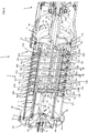
- La description suivante met en évidence les caractéristiques et avantages de l'appareil de coiffure selon l'invention dans un mode de réalisation non limitatif s'appuyant sur des figures, parmi lesquelles :
- Les
figures 1 et 2 illustrent, selon un premier plan de coupe longitudinale, un appareil de coiffure objet de l'invention avec des bagues respectivement en position écartée et en position resserrée ; - Les
figures 3 et 4 illustrent, selon un second plan de coupe longitudinale perpendiculaire au premier plan précité, ledit appareil de coiffure desfigures 1 et 2 avec les bagues respectivement en position écartée et en position resserrée ; - Les
figures 5 et6 illustrent essentiellement le mandrin avec les bagues resserrées correspondant auxfigures 2 et4 , selon deux angles de vue isométrique et selon deux plans de coupe différents ; - La
figure 7 est une vue isométrique depuis le côté proximal du mandrin, qui met en évidence les bagues et les éléments agencés à l'intérieur du tambour ; - La
figure 8 est une vue en plan depuis le côté distal du mandrin, qui met également en évidence les éléments agencés à l'intérieur du tambour ; - La
figure 9 illustre un manchon constituant une brosse, les poils de la brosse n'étant toutefois pas représentés pour une meilleure compréhension de cette figure ; - Tel qu'illustré sur les
figures 1 à 4 , l'appareil de coiffure 1 comprend un corps 2 et un mandrin 3. Le mandrin 3 est agencé dans le prolongement longitudinal du corps 2, selon un axe longitudinal X. Ce mandrin 3 comprend un tambour 4 qui comporte une portion proximale 5 et une portion distale 6, comme illustré plus en détail sur lesfigures 3, 4 et6 . La portion distale 6 est montée à coulissement selon l'axe longitudinal X à l'intérieur de la portion proximale 5. - Le mandrin 3 comprend une bague proximale 7, cinq bagues intermédiaires 8-12 et une bague distale 13, comme illustré sur les
figures 1 à 3 . Les bagues proximale 7, intermédiaires 8-12 et distale 13 sont illustrées également sur lesfigures 5 à 7 . Le nombre de bagues intermédiaires est variable selon la longueur du mandrin 3 voire selon le nombre de pressions sur les cheveux que l'on souhaite réaliser en une seule opération de traitement des cheveux. On choisira de préférence entre quatre et huit bagues intermédiaires. En regard de cesfigures 1 à 7 , on constate que la bague proximale 7, les bagues intermédiaires 8-12 et la bague distale 13 ont une forme en créneau dans un plan de coupe longitudinal passant par l'axe longitudinal X. - Comme le montrent plus en détail les
figures 5 et6 , la bague proximale 7 comprend un cylindre interne 7a et un cylindre externe 7b reliés entre eux par un épaulement 7c, et comprend également une base circulaire 7d qui ferme en partie l'extrémité distale du cylindre externe 7b. De manière similaire, les bagues intermédiaires 8-12 comprennent chacune un cylindre interne 8a-12a et un cylindre externe 8b-12b reliés entre eux par un épaulement 8c-12c, et une base circulaire 8d-12d qui ferme en partie l'extrémité distale du cylindre externe 8b-12b. La bague distale 13 comprend également un cylindre interne 13a et un cylindre externe 13b reliés entre eux par un épaulement 13c, mais est dépourvue de base circulaire. L'extrémité distale 14 du cylindre externe 13b de la bague distale 13 est emboîtée sur une tête épaulée 15 de la portion distale 6 du tambour 4, comme l'illustrent notamment lesfigures 5 et6 . La base circulaire 7d de la bague proximale 7 est montée à coulissement selon l'axe longitudinal X sur le cylindre interne 8a de la première bague intermédiaire 8. De même, les bases circulaires 8d-11d des bagues intermédiaires 8-11 sont successivement montées à coulissement selon l'axe longitudinal X sur les cylindres internes 9a-12a des bagues intermédiaires suivantes 9-12. La base circulaire 12d de la dernière bague intermédiaire 12 est montée à coulissement selon l'axe longitudinal X sur le cylindre interne 13a de la bague distale 13. - L'appareil de coiffure 1 comprend une pièce de liaison 16 illustrée sur les
figures 1 à 6 . Cette pièce de liaison 16 est agencée selon l'axe longitudinal X et comprend un volant 17 assujetti à un arbre creux 18. L'extrémité distale du volant comprend un épaulement 17a illustré plus en détail enfigures 5 et6 . Tel qu'illustré plus en détail sur lesfigures 1 à 6 , la portion proximale 5 du tambour 4 comprend une base 19 dont l'extrémité proximale comprend également un épaulement 19a. Cette base 19 est assemblée avec le volant 17 au moyen de vis de fixation logés dans des emplacements 20 prévus pour leur vissage, comme illustré enfigures 1 à 6 , ledit assemblage permettant de constituer une gorge 21 de par la disposition en vis-à-vis desdits épaulements 17a, 19a respectivement sur le volant 17 et sur la base 19, comme illustré notamment enfigures 5 et6 . - Tel qu'illustré sur les
figures 1 à 6 , le corps 2 comprend à son extrémité distale 2a une portion cylindrique interne 22 dans laquelle viennent se loger le volant 17 de la pièce de liaison 16 et en partie la base 19 de la portion proximale 5 du tambour 4. Cette portion cylindrique interne 22 comprend des protubérances 23 munies chacune d'un ergot 23a, de préférence six, uniformément répartis autour de ladite portion cylindrique interne 22. Ces ergots 23a viennent se loger dans la gorge 21 agencée entre ledit volant 17 et ladite base 19, comme illustré plus en détail enfigures 5 et6 , et assurent un montage en liaison pivot selon l'axe longitudinal X de la pièce de liaison 16 et de la portion proximale 5, vis-à-vis du corps 2. L'arbre creux 18 de la pièce de liaison 16 s'étend dans le corps 2, selon l'axe longitudinal X, et est assujetti au niveau de son extrémité proximale 18a, à l'extrémité distale 24b d'un arbre de transmission 24, également creux, tel qu'illustré enfigures 1 à 4 et6 . L'extrémité proximale 24a de cet arbre de transmission 24 est connectée à un moteur 25 d'entraînement en rotation. Deux bagues 26a, 26b sont montées en complément entre l'arbre de transmission 24 et la paroi interne 27 du corps 2, en sorte d'assurer la liaison pivot selon l'axe longitudinal X de l'ensemble portion proximale 5 du tambour 4, pièce de liaison 16, arbre de transmission 24, vis-à-vis du corps 2. - Tel qu'illustré sur les
figures 1, 2 ,5 à 8 , la portion proximale 5 du tambour 4 est creuse et comprend deux logements 28, 29 agencés longitudinalement en vis-à-vis sur la paroi interne 30 cylindrique de ladite portion proximale 5. Ces logements 28, 29 sont configurés pour recevoir des éléments chauffants 31, 32, de préférence des capteurs à coefficient de température positif dit CTP. Ces éléments chauffants 31, 32 sont raccordés électriquement au moyen de câbles 33, 34 qui passent au travers de l'arbre creux 18 de la pièce de liaison 16 et de l'arbre de transmission 24, les extrémités 33a, 34a de ces câbles 33, 34 étant raccordées au moyen d'un connecteur électrique tournant 35 à une carte de gestion électronique (non illustrée sur les figures), comme le montrent lesfigures 1 et 2 . Ainsi, les éléments chauffants 31, 32 sont en contact direct avec le tambour 4, lui-même en contact avec les bagues 7-13. Cela permet de régler avec une plus grande précision la température de chauffe des bagues 7-13 et offre une plage de réglage de la température de chauffe plus importante étant donné que l'on améliore la transmission de chaleur par conduction thermique à travers le tambour 4, par ce contact direct avec les éléments chauffants 31, 32. On choisira pour cela une matière assurant une bonne conduction thermique pour la mise en œuvre du tambour 4, par exemple l'aluminium. - Tel qu'illustré en
figures 1 à 4 , un ventilateur 36 est agencé à l'intérieur du corps 2, au niveau de son extrémité proximale 2b. Un capot ajouré 37 ferme cette extrémité proximale 2b et assure une prise d'air lors de la mise en marche du ventilateur 36, lequel souffle alors l'air dans la chambre 38 du corps 2. Un second élément chauffant 39, par exemple des capteurs à coefficient de température positif, est agencé dans la partie centrale de la chambre 38. L'air soufflé par le ventilateur 36 passe donc au travers de ce second élément chauffant 39, ce qui permet de le chauffer, puis cet air chauffé se propage dans ladite chambre 38 jusqu'à l'extrémité distale 2a du corps 2. - Tel qu'illustré sur les
figures 1 à 6 , les protubérances 23 sur la portion cylindrique interne 22 du corps 2 permettent de maintenir un espacement avec le volant 17 de la pièce de liaison 16 et la base 19 de la portion proximale 5 du tambour 4, ce qui permet de constituer un conduit qui communique avec la chambre 38 et qui débouche sur des sorties d'air 40 au niveau de l'extrémité distale 2a du corps 2. Ces sorties d'air 40 permettent de souffler l'air chaud dans le sens longitudinal, depuis la base 3a du mandrin 3, au niveau de la surface des cylindres externes 7b-13b des bagues 7-13 constituant la paroi externe dudit mandrin 3. - Tel qu'illustré sur les
figures 1 à 6 , les portions proximale 5 et distale 6 du tambour 4 sont creuses et définissent une chambre 41. Le volant 17 de la pièce de liaison 16 comprend quatre ouvertures 42 qui communiquent avec la chambre 41 du tambour 4. Ainsi, l'air chaud est propulsé par le ventilateur 36 dans la chambre 41, jusqu'à la tête épaulée 15 de la portion distale 6 du tambour 4. Un capot de fermeture 43 comprend des plots 44 qui permettent sa fixation avec la tête épaulée 15, au moyen de vis (non illustrées). Ces plots 44 permettent de conserver un espacement 45 entre la paroi interne 43a du capot de fermeture 43 et la tête épaulée 15, qui forme un canal communiquant avec ladite chambre 41. En outre, la paroi interne 43a présente une forme incurvée telle qu'illustrée enfigures 1 à 3 , permettant audit espacement 45 de constituer un déflecteur avec une sortie d'air 46 au niveau de la tête 3b du mandrin 3, orientée vers les bagues 7-13. Cette sortie d'air 46 permet de souffler l'air chaud vers les bagues 7-13 dans le sens de l'axe longitudinal X, au niveau de la surface des cylindres externes 7b-13b. - L'appareil de coiffure 1 comprend une pièce de transmission 47 illustrée sur les
figures 1 à 8 . Cette pièce de transmission 47 comprend deux bras 48, 49 qui s'étendent longitudinalement dans la chambre 41 du tambour 4. Ces bras 48, 49 sont montés en glissière selon l'axe longitudinal X, au travers de deux orifices débouchant 50, 51 agencés sur le volant 17 de la pièce de liaison 16. Ainsi, grâce à cette liaison glissière, l'entrainement en rotation de la pièce de liaison 16, par le biais du moteur 25, permet d'entrainer concomitamment la pièce de transmission 47 en rotation selon l'axe longitudinal X. La pièce de transmission 47 comprend un croisillon 52 qui est assujetti aux extrémités distales 48b, 49b des bras 48, 49, tel qu'illustré notamment sur lesfigures 1 et 2 . De même, la pièce de transmission 47 comprend un anneau de guidage 53 qui est assujetti aux extrémités proximales 48a, 49a des bras et qui est monté à coulissement vis-à-vis de l'arbre creux 18 de la pièce de liaison 16, selon l'axe longitudinal X. Le croisillon 52 et l'anneau de guidage 53 sont entraînés en rotation selon l'axe longitudinal X avec les deux bras 48, 49 auxquels ils sont assujettis, lors de la mise en marche du moteur 25. - Tel qu'illustré sur les
figures 1 à 4 , l'appareil de coiffure 1 comprend une gâchette 54 qui est montée en liaison pivot 55 sur le côté externe du corps 2 et permet l'actionnement de deux bielles 56, 57 auxquelles elle est assujettie. Les extrémités distales 56b, 57b de ces bielles 56, 57 comprennent chacune une lumière 58, 58' de forme oblongue. Un anneau de glissement 59 est en contact glissant avec l'anneau de guidage 53, tel qu'illustré sur cesfigures 1 à 4 et6 . L'anneau de glissement 59 comprend deux tétons 60, 61 qui s'étendent en opposition, comme illustré notamment enfigures 3, 4 et6 , et viennent se loger respectivement dans les lumières 58, 58' sur les bielles 56, 57. L'anneau de glissement 59 est également monté à coulissement selon l'axe longitudinal X, vis-à-vis de l'arbre creux 18 de la pièce de liaison 16. Un actionnement de la gâchette 54, d'une première position illustrée enfigure 2 vers une seconde position illustrée enfigure 1 , permet de translater l'anneau de glissement 59 vers l'avant de l'arbre creux 18, ce qui entraîne concomitamment la translation vers l'avant de l'anneau de guidage 53 et, donc, de la pièce de transmission 47. Lors de l'activation du moteur 25, l'anneau de guidage 53 est entraîné en rotation, comme expliqué précédemment, et frotte donc sur l'anneau de glissement 59 qui est assujetti aux bielles 56, 57. - Tel qu'illustré sur les
figures 1 à 6 , l'appareil de coiffure 1 comprend une tige proximale 62, cinq tiges intermédiaires 63-67 et une tige distale 68. La tige proximale 62 est agencée radialement et passe au travers de deux lumières 69, 70 de forme oblongue agencées longitudinalement sur le cylindre interne 7a de la bague proximale 7, les extrémités 62a, 62b de la tige proximale 62 se logeant dans deux trous 103a, 103b agencés radialement sur la portion proximale 5 du tambour 4. Ainsi, la bague proximale 7 est montée en liaison glissière vis-à-vis de la portion proximale 5, selon l'axe longitudinal X, avec une course de déplacement se limitant à la longueur des lumières 69, 70. - Tel qu'illustré notamment sur les
figures 1, 2 ,5 et6 , la portion proximale 5 du tambour 4 comprend deux lumières longitudinales 71, 72 qui s'étendent parallèlement à l'axe longitudinal X et qui sont disposées en vis-à-vis sur cette portion proximale 5. De même, la portion distale 6 du tambour 4 comprend deux rainures 73, 74 qui débouchent à l'extrémité proximale 6a de ladite portion distale 6 et qui sont disposées en vis-à-vis respectivement dans l'alignement des lumières longitudinales 71, 72, comme l'illustrent notamment lesfigures 5 et6 . - Tel que l'illustrent notamment les
figures 1 à 6 , les tiges intermédiaires 63-67 sont agencées radialement et passent chacune au travers des deux lumières longitudinales 71, 72. Les deux extrémités 63a-67a de ces tiges intermédiaires 63-67 passent respectivement au travers de deux trous débouchant 75a- 79a, illustrés enfigure 6 , agencés radialement et en vis-à-vis sur les cylindres internes 8a-12a des bagues intermédiaires 8-12, qui sont montés à coulissement selon l'axe longitudinal X vis-à-vis de la portion proximale 5 du tambour 4. Cette conception permet de réaliser un montage en liaison glissière des bagues intermédiaires 8-12 vis-à-vis de la portion proximale 5 du tambour, selon l'axe longitudinal X. En outre, ces deux extrémités 63a-67a, 63b-67b des tiges intermédiaires 63-67 se logent à l'intérieur des bagues précédentes 7-11 formant des créneaux, dans les parties correspondant aux cylindres externe 7b-11b desdites bagues précédentes 7-11, tel qu'illustré enfigure 6 . Par ailleurs, les cylindres internes 8a-12a des bagues intermédiaires 8-12 sont montés à coulissement selon l'axe longitudinal X vis-à-vis des bases circulaires 7d-11d des bagues précédentes 7-11, comme déjà expliqué précédemment. Ainsi, chaque bague intermédiaire 8-12 peut coulisser selon l'axe longitudinal X vis-à-vis de la bague 7-11 qui la précède, soit vers l'aval jusqu'à ce que les extrémités 63a-67a, 63b-67b de la tige intermédiaire 63-67 viennent en butée contre le côté interne de la base circulaire 7d-11d de la bague 7-11 précédente, comme cela apparaît sur lafigure 3 , soit vers l'amont jusqu'à ce que l'épaulement 8c-12c sur la bague intermédiaire 8-12 vienne en butée contre la face externe de la base circulaire 7d-11d de la bague précédente 7-11, comme cela apparaît notamment sur lesfigures 5 et6 . En outre, la rotation de la bague intermédiaire 8-12 vis-à-vis de la bague 7-11 qui la précède est bloquée par le biais des lumières longitudinales 71-72 au travers desquelles passent les tiges intermédiaires 63-67, ce qui assure un montage en liaison glissière avec une course limitée de chaque bague intermédiaire 8-12 vis-à-vis de la bague 7-11 qui la précède. - De manière comparable aux caractéristiques précitées, tel que l'illustre notamment la
figure 6 , la tige distale 68 est agencée radialement et passe au travers des deux lumières longitudinales 71, 72 de la portion proximale 5 du tambour 4. Les deux extrémités 68a, 68b de la tige distale 68 passent respectivement dans deux trous débouchant 80a agencés radialement en vis-à-vis sur le cylindre interne 13a de la bague distale 13, qui est monté à coulissement selon l'axe longitudinal X vis-à-vis de la portion proximale 5 du tambour 4. Cette conception permet de réaliser un montage en liaison glissière de la bague distale 13 vis-à-vis de la portion proximale 5 du tambour, selon l'axe longitudinal X. En outre, ces deux extrémités 68a, 68b de la tige distale 68 se logent à l'intérieur de la bague intermédiaire 12 qui la précède, dans la partie correspondant au cylindre externe 12b de ladite bague intermédiaire 12. Comme expliqué précédemment, le cylindre interne 13a de la bague distale 13 est monté à coulissement selon l'axe longitudinal X vis-à-vis de la base circulaire 12d de la bague intermédiaire 12 précédente. Ainsi, la bague distale 13 peut coulisser selon l'axe longitudinal X vis-à-vis de la bague intermédiaire 12 qui la précède, soit vers l'aval jusqu'à ce que les extrémités 68a, 68b de la tige distale 68 viennent en butée contre le côté interne de la base circulaire 12d de ladite bague intermédiaire 12, soit vers l'amont jusqu'à ce que l'épaulement 13c sur la bague distale 13 vienne en butée contre la face externe de la base circulaire 12d de la bague intermédiaire 12. En outre, la rotation de la bague distale 13 vis-à-vis de la bague intermédiaire 12 est bloquée par le biais des lumières longitudinales 71-72 au travers desquelles passe la tige distale 68, ce qui assure un montage en liaison glissière avec une course limitée de la bague distale 13 vis-à-vis de la bague intermédiaire 12 qui la précède. La tige distale 68 est en outre assujettie au croisillon 52 qu'elle traverse, comme l'illustrent notamment lesfigures 3 et5 . Les extrémités 68a, 68b de la tige distale 68 passent respectivement au travers des deux rainures 73,74 de la portion distale 6 du tambour, comme l'illustre lafigure 6 , ce qui bloque la rotation de la portion distale 6 vis-à-vis de la bague distale 13, selon l'axe longitudinal X. - Lors de l'activation de la gâchette 54 de la première position illustrée en
figure 2 vers la seconde position illustrée enfigure 1 , la pièce de transmission 47 subit une translation vers l'avant selon l'axe longitudinal X, ce qui, du fait de l'assujettissement entre le croisillon 52, la tige distale 68 et la bague distale 13, assure le déplacement vers l'avant de ladite bague distale 13 et de la portion distale 6 du tambour 4, ces dernières translatant selon l'axe longitudinal X vis-à-vis de la portion proximale 5 du tambour 4. Concomitamment, la bague distale 13 translate vis-à-vis de la bague intermédiaire 12 qui la précède jusqu'à ce que les extrémités 68a, 68b de la tige distale 68 viennent en butée contre la base circulaire 12d de ladite bague intermédiaire 12, ce qui entraîne alors la translation vers l'avant selon l'axe longitudinal X de cette bague intermédiaire 12, vis-à-vis de la bague intermédiaire 11 qui la précède. Lorsque les extrémités 67a, 67b de la tige intermédiaire 67 viennent en butée contre la base circulaire 11d de la bague intermédiaire 11 précédente, celle-ci translate à son tour vis-à-vis de la bague intermédiaire 10 qui la précède. L'action se répète ainsi de suite jusqu'à ce que la dernière bague intermédiaire 8 entraîne en translation la bague proximale 7, une fois que les extrémités 63a, 63b de la dernière tige intermédiaire 63 viennent en butée contre la base circulaire 7d de ladite bague proximale 7. La bague proximale 7 translate selon l'axe longitudinal X vis-à-vis de la portion proximale 5 du tambour et de la tige proximale 62 jusqu'à ce que les lumières 69,70 sur la bague proximale 7 viennent en butée sur les extrémités 62a, 62b de la tige proximale 62, ce qui stoppe le déploiement du mandrin 3. Dans cette position déployée du mandrin 3, la bague proximale 7 présente un écartement 81 vis-à-vis de la base 19 de la portion proximale 5 du tambour 4 et les bagues 7-13 présentent entre elles des écartements 82-87. Le dispositif d'actionnement tel que décrit précédemment permet donc de déployer successivement, de manière télescopique, les bagues 7-13 jusqu'à ce qu'elles laissent apparaître entre elles les écartements 81-87 qui permettent l'insertion de mèches de cheveux. - L'appareil de coiffure 1 est configuré pour que la gâchette 54 revienne automatiquement dans la position illustrée en
figure 2 lorsque l'utilisateur relâche cette gâchette 54, après avoir positionné les cheveux dans les écartements 81-87. Pour cela, des moyens de rappel assurent une translation automatique de la pièce de transmission 47, une fois la gâchette 54 relâchée. De préférence, ces moyens de rappel sont constitués de deux ressorts (non illustrés sur les figures) qui sont agencés respectivement sur les deux bras 48, 49. Ces deux ressorts peuvent être agencés dans la partie des bras 48, 49 située entre le volant 17 de la pièce de liaison 16 et le croisillon 52 ; dans ce cas les ressorts travaillent en extension. On pourrait au contraire prévoir un agencement de ces deux ressorts dans la partie des bras 48, 49 située entre le volant 17 et l'anneau ou la bague de guidage 53, lesdits ressorts travaillant dans ce cas en compression. La constante de raideur des ressorts sera dimensionnée pour assurer ce retour automatique de la gâchette 54. On pourrait cependant prévoir une constante de raideur moins importante, en actionnant préalablement la gâchette 54 manuellement pour la ramener en position illustrée enfigure 2 , les ressorts poussant alors concomitamment la pièce de transmission 47 vers l'arrière en la maintenant plaquée contre l'anneau ou la bague de glissement 59. - Lorsque la pièce de transmission 47 translate vers l'arrière de l'appareil de coiffure 1, selon l'axe longitudinal X, celle-ci entraîne concomitamment la translation de la bague distale 13 et de la portion distale 6 du tambour 4 qui coulissent par rapport à la portion proximale 5 du tambour 4. Les cheveux disposés dans l'écartement distal 87 situé entre l'épaulement 13c de la bague distale 13 et la base circulaire 12d de la bague intermédiaire 12, sont alors compressés jusqu'à atteindre une limite de compression. Cette limite de compression entraîne alors le déplacement concomitant de la bague distale 13 et de la bague intermédiaire 12 précédente. Les cheveux disposés dans le dernier écartement intermédiaire 86 sont à leur tour compressés jusqu'à atteindre une limite de compression entraînant le déplacement concomitant de la bague distale 13 et des deux dernières bagues intermédiaires 12-11. L'action se répète ainsi de suite jusqu'à ce que la bague proximale 7 translate concomitamment avec la bague distale 13 et toutes les bagues intermédiaires 8-12. Une fois que les cheveux disposés dans l'écartement proximal 81 situé entre l'épaulement 7c de la bague proximale 7 et la base 19 de la portion proximale 5 du tambour 4, sont compressés, les ressorts de rappel de la pièce de transmission 47 équilibrent la pression exercée sur les cheveux disposés dans les écartements 81-87 entre les bagues 7-13, indépendamment des épaisseurs de cheveux situées dans ces écartements 81-87, étant donné le rétrécissement ou le retour télescopique des bagues 7-13 du mandrin 3, en partant de la bague distale 13 jusqu'à la bague proximale 7.
- L'appareil de coiffure 1 comprend une pièce de blocage 88 apparaissant sur les
figures 1 à 8 . Cette pièce de blocage 88 comprend un axe d'extrémité 89 qui se divise en deux branches 90,91 qui s'étendent parallèlement à l'axe longitudinal X, aux extrémités desquelles sont agencés respectivement deux doigts 92, 93. Une barre de renfort 94 permet de rigidifier les deux branches 90, 91. L'axe d'extrémité 89 est assujetti à un bouton de commande 95 qui est monté en liaison pivot selon l'axe longitudinal X, vis-à-vis du capot de fermeture 43. Le bouton de commande 95 permet d'actionner la rotation de la pièce de blocage 88 selon l'axe longitudinal X, d'une position déverrouillée selon laquelle les doigts 92, 93 sont dégagés vis-à-vis de la première tige intermédiaire 63, comme illustré enfigures 5 et7 , vers une position verrouillée selon laquelle lesdits doigts 92, 93 sont engagés entre la tige proximale 62 et la première tige intermédiaire 63, et viennent en butée contre ladite première tige intermédiaire 63. Dans cette position verrouillée, l'actionnement de la gâchette 54 - de manière similaire à l'actionnement permettant de passer d'une position de la gâchette illustrée à lafigure 2 vers celle illustrée à lafigure 1 - permet de translater vers l'avant la pièce de transmission 47, ce qui déplace concomitamment la bague distale 13, la portion distale 6 du tambour avec le capot de fermeture 43 et, de ce fait, la pièce de blocage 88. Les doigts 92, 93 entraînent alors la première tige intermédiaire 63, ce qui déplace concomitamment les bagues intermédiaires 8-12 et la bague distale 13 qui restent jointives. Lorsque les extrémités 63a, 63b de la première tige intermédiaire 63 viennent en contact de la face interne de la base circulaire 7d de la bague proximale 7, cette dernière est alors également entraînée en translation selon l'axe longitudinal X, avec les autres bagues 8-13 jointives, jusqu'à ce que les lumières 69, 70 sur le cylindre interne 7a viennent en butée contre la tige proximale 62. Seuls apparaissent alors l'écartement proximal 81 et le premier écartement intermédiaire 82, dans lesquels peuvent être placés des cheveux. Le relâchement de la gâchette 54 permet la translation concomitante vers l'arrière, sous l'action des ressorts, de la bague distale 13 et des bagues intermédiaires 8-12, ce qui resserre d'abord le premier écartement intermédiaire 82 jusqu'à ce que la bague proximale 7 translate également, l'écartement proximal 81 se resserrant alors à son tour. Les bagues 8-13 en position jointive forment un rouleau autour duquel peuvent être enroulés les cheveux qui sont maintenus à leurs extrémités, au niveau des pointes, pour la réalisation d'un bouclage. On pourrait envisager une variante de réalisation selon laquelle toutes les bagues 7-13 se déplaceraient jointivement et concomitamment pour ne laisser apparaître que l'écartement proximal 81 lors de l'activation de la gâchette 54. Il conviendrait dans ce cas d'ajouter un élément de butée (non illustré) complémentaire assujetti à la bague proximale 7, sur lequel viendraient en contact les doigts 92, 93 de la pièce de blocage 88. - Tel qu'illustré sur la
figure 9 , l'appareil de coiffure comprend un manchon 96 qui est configuré pour être positionné autour du mandrin 3 lorsque les bagues 7-13 sont disposées jointivement. Le manchon 96 comprend des poils (non illustrés sur lafigure 9 pour une meilleure lecture de celle-ci) qui sont répartis radialement et uniformément sur le manchon au niveau de trous 97 qui permettent l'assemblage de ces poils sur le manchon 96. Le manchon 96 comprend deux parties semi-cylindriques 98, 99 qui sont montées en liaison pivot 100 l'une par rapport à l'autre selon un axe longitudinal X1 parallèle à l'axe longitudinal X au niveau de leurs premiers bords 98a, 99a, ce qui permet d'ouvrir le manchon 96 pour le positionner autour du mandrin 3 puis de refermer le manchon pour le serrer autour du mandrin 3. Les seconds bords 98b, 99b des deux parties 98, 99 sont maintenus entre eux en position fermée, au moyen de deux clips 101, 102, illustrés enfigure 9 . Ce manchon 96 permet d'utiliser l'appareil de coiffure 1 pour le brossage des cheveux. - Ainsi, les caractéristiques précitées de l'appareil de coiffure 1 offrent plusieurs utilisations possibles. En positionnant et en pressant les cheveux dans les écartements 81-87 entre les bagues 7-13 et la base 19 de la portion proximale 5 du tambour 4, à proximité des racines des cheveux, puis en translatant l'appareil de coiffure 1 des racines vers les pointes des cheveux, on réalise un lissage. En positionnant et en pressant les pointes des cheveux dans l'écartement 81 entre ladite base 19 et la bague proximale 7, puis en enroulant les cheveux autour des bagues 7-13 jointives et formant un rouleau, on réalise un bouclage. En ajoutant le manchon 96 autour du mandrin 3, on réalise un brossage des cheveux. Ces différentes opérations peuvent en outre être réalisées sur cheveux secs ou humides, en utilisant les moyens de chauffage, c'est-à-dire les éléments chauffants 31,32 qui assurent une conduction thermique à travers le tambour 4 et les bagues 7-13 et, en complément ou indépendamment, le ventilateur 36 et le second élément chauffant 39 qui permettent le soufflage d'air chaud par la base 3a et la tête 3b du mandrin 3, le long de la surface externe dudit mandrin 3.
- L'appareil de coiffure 1 comprend d'autres caractéristiques comme un système de commande des moyens de chauffage pour le réglage de la température de chauffe des éléments chauffants 31, 32, 39 et pour le réglage de la vitesse du ventilateur 36.
- On peut envisager des variantes de réalisation du dispositif d'actionnement des bagues 7-13 tout en conservant un resserrage de ces bagues 7-13 indépendamment les unes des autres et une pression constante entre elles. On peut par exemple remplacer la gâchette 54 et les bielles 56,57 par un autre système d'actionnement de la pièce de transmission 47. On peut aussi modifier le système de transmission, c'est-à-dire la pièce de transmission 47, la pièce de liaison 16, les tiges 62-68, la forme des bagues 7-13, les moyens de rappel (non illustré) et le tambour 4 constitués des deux portions proximale 5 et distale 6, tout en parvenant à un montage télescopique similaire des bagues 7-13 qui permet d'écarter entre elles les bagues 7-13, puis de resserrer indépendamment lesdites bagues 7-13 en conservant une pression constante malgré des variations d'épaisseurs de cheveux dans les écartements 81-87.
- On peut aussi envisager des variantes de systèmes de blocage des bagues 7-13 en remplacement de la pièce de blocage 88, en sorte d'écarter de manière jointive les bagues 7-13 vis-à-vis de la base 19 du tambour 4.
- On peut aussi trouver des variantes d'éléments chauffants 31, 32, en remplacement des capteurs à coefficient de température positif. On peut aussi prévoir de fixer les éléments chauffant 31, 32 directement sur la paroi interne 30 du tambour 4, sans prévoir les logements 28, 29.
- Le mode de réalisation décrit précédemment présente pour avantage de limiter l'encombrement de la chambre 41 du tambour 4, ce qui contribue avantageusement à agencer le dispositif d'actionnement des bagues 7-13 directement dans ladite chambre 41 et à souffler de l'air chaud par la tête 3b du mandrin 3, en complément d'un soufflage d'air chaud par la base 3a dudit mandrin 3.
Claims (15)
- Appareil de coiffure (1) comprenant un corps (2) configuré pour manipuler l'appareil, un mandrin (3) de coiffage des cheveux qui est creux et qui prolonge le corps selon un axe longitudinal (X), caractérisé en ce qu'il comprend deux éléments chauffants (31, 32) par conduction thermique agencés sur une paroi interne (30) du mandrin et qui s'étendent le long de la paroi interne (30) du mandrin (3).
- Appareil de coiffure (1) selon la revendication 1, dans lequel le mandrin (3) comprend un tambour (4) et des bagues (7-13) montées coulissantes selon l'axe longitudinal (X) sur une paroi externe dudit tambour, lesdites bagues étant configurées pour être positionnées jointivement entre elles de sorte à constituer un rouleau ou pour être écartées entre elles de sorte à permettre l'insertion de cheveux dans les écartements (81-87) entre lesdites bagues, l'au moins un élément chauffant (31, 32) étant agencé sur la paroi interne (30) du tambour.
- Appareil de coiffure (1) selon la revendication 2, lequel comprend un dispositif d'actionnement des bagues (7-13) configuré au moins pour écarter les bagues et pour resserrer indépendamment ces bagues les unes contre les autres en fonction des épaisseurs de cheveux disposées entre lesdites bagues.
- Appareil de coiffure (1) selon la revendication 3, dans lequel les bagues (7-13) sont configurées pour être montées coulissantes successivement les unes vis-à-vis des autres selon l'axe longitudinal (X), le dispositif d'actionnement comprenant un système de transmission configuré à l'intérieur du mandrin (3) pour coulisser de manière télescopique les bagues lors de leur écartement et lors de leur resserrage, l'au moins un élément chauffant (31,32) étant disposé autour dudit système de transmission.
- Appareil de coiffure (1) selon l'une des revendications 3 ou 4, lequel comprend un système de blocage (88) configuré pour agir sur le dispositif d'actionnement et déplacer concomitamment les bagues (7-13) en position jointive dans une position écartée par rapport à une base (19) du mandrin (3) ou inversement dans une position resserrée vis-à-vis de ladite base, lors de l'activation dudit dispositif d'actionnement.
- Appareil de coiffure (1) selon la revendication 5, lequel comprend un bouton de commande (95) du système de blocage (88) configuré pour activer et désactiver ledit système de blocage.
- Appareil de coiffure (1) selon l'une des revendications 2 à 6, dans lequel le tambour (4) comprend une portion proximale (5) et une portion distale (6), la portion distale étant montée coulissante dans la portion proximale selon l'axe longitudinal (X), l'au moins un élément chauffant (31, 32) étant monté sur la paroi interne de la portion proximale (5).
- Appareil de coiffure (1) selon l'une des revendications 1 à 7, dans lequel le mandrin (3) est monté en liaison pivot vis-à-vis du corps (2), ledit appareil comprenant des moyens d'entraînement en rotation (42, 43) du mandrin.
- Appareil de coiffure (1) selon la revendication 8, dans lequel l'au moins un élément chauffant (31, 32) est raccordé électriquement à une carte électronique de gestion fixée dans le corps (2), au moyen d'un connecteur électrique tournant (35).
- Appareil de coiffure (1) selon l'une des revendications 1 à 9, lequel comprend des moyens de soufflage d'air chaud (36, 39) agencés dans le corps (2), le mandrin (3) étant configuré pour éjecter l'air chaud soufflé.
- Appareil de coiffure (1) selon la revendication 10, dans lequel les moyens de soufflage d'air chaud (36, 39) et le mandrin (3) sont configurés pour éjecter l'air chaud soufflé au travers d'au moins une parmi deux sorties d'air (40, 46) agencées respectivement au niveau d'une base (3a) et d'une tête (3b) dudit mandrin.
- Appareil de coiffure (1) selon la revendication 11, dans lequel la base (3a) du mandrin (3) et le corps (2) sont configurés pour former un conduit qui débouche sur la première sortie (40) au niveau de ladite base, l'air chaud soufflé circulant dans ledit conduit.
- Appareil de coiffure (1) selon l'une des deux revendications 11 ou 12, lequel comprend un capot (43) de fermeture de la tête (3b) du mandrin (3), ledit capot et ladite tête étant configurés pour former un conduit déflecteur (45) qui communique avec l'intérieur (41) du mandrin et qui débouche sur la seconde sortie (46) au niveau de ladite tête, l'air chaud soufflé circulant à l'intérieur du mandrin puis dans le conduit déflecteur.
- Appareil de coiffure (1) selon l'une des revendications 1 à 13, dans lequel le mandrin (3) comprend une paroi interne (30) sur laquelle sont agencés deux logements (28, 29) configurés pour recevoir les éléments chauffants (31, 32).
- Appareil de coiffure (1) selon l'une des revendications 1 à 14, dans lequel les éléments chauffants (31, 32) s'étendent selon l'axe longitudinal (X) sur au moins la moitié de la longueur du mandrin (3).
Applications Claiming Priority (2)
| Application Number | Priority Date | Filing Date | Title |
|---|---|---|---|
| FR1463429A FR3031020B1 (fr) | 2014-12-30 | 2014-12-30 | Appareil de coiffure de type brosse avec moyens de chauffage optimises |
| PCT/FR2015/053723 WO2016108014A1 (fr) | 2014-12-30 | 2015-12-22 | Appareil de coiffure de type brosse avec moyens de chauffage optimises |
Publications (2)
| Publication Number | Publication Date |
|---|---|
| EP3240454A1 EP3240454A1 (fr) | 2017-11-08 |
| EP3240454B1 true EP3240454B1 (fr) | 2021-12-22 |
Family
ID=52684521
Family Applications (1)
| Application Number | Title | Priority Date | Filing Date |
|---|---|---|---|
| EP15823365.0A Active EP3240454B1 (fr) | 2014-12-30 | 2015-12-22 | Appareil de coiffure de type brosse avec moyens de chauffage optimisés |
Country Status (4)
| Country | Link |
|---|---|
| EP (1) | EP3240454B1 (fr) |
| CN (1) | CN107105853B (fr) |
| FR (1) | FR3031020B1 (fr) |
| WO (1) | WO2016108014A1 (fr) |
Families Citing this family (2)
| Publication number | Priority date | Publication date | Assignee | Title |
|---|---|---|---|---|
| FR3056085B1 (fr) * | 2016-09-21 | 2020-12-11 | Seb Sa | Appareil de coiffure equipe d'un capot de protection mobile |
| US12376660B2 (en) | 2023-01-17 | 2025-08-05 | Sharkninja Operating Llc | Hot brush |
Citations (1)
| Publication number | Priority date | Publication date | Assignee | Title |
|---|---|---|---|---|
| FR2447162A1 (fr) * | 1979-01-27 | 1980-08-22 | Wik Elektro Hausgeraete | Appareil de coiffure |
Family Cites Families (12)
| Publication number | Priority date | Publication date | Assignee | Title |
|---|---|---|---|---|
| JPS54136961A (en) * | 1978-04-15 | 1979-10-24 | Matsushita Electric Works Ltd | Hair curler |
| JPS54136959A (en) | 1978-04-15 | 1979-10-24 | Matsushita Electric Works Ltd | Hair curler |
| JPS6472704A (en) * | 1987-09-14 | 1989-03-17 | Matsushita Electric Works Ltd | Hair curler |
| JP2733094B2 (ja) | 1989-05-25 | 1998-03-30 | 松下電工株式会社 | スチーム式ヘアカール器 |
| JPH03267006A (ja) | 1990-03-15 | 1991-11-27 | Matsushita Electric Works Ltd | ヘアセット器 |
| JPH0675526B2 (ja) | 1992-04-27 | 1994-09-28 | 九州日立マクセル株式会社 | スチームヘアーセット器 |
| FR2960747A1 (fr) * | 2010-06-07 | 2011-12-09 | Seb Sa | Appareil de coiffure avec mandrin motorise |
| CN102783802B (zh) * | 2011-05-16 | 2016-04-06 | 浙江美森电器有限公司 | 卷发器 |
| CN202168547U (zh) * | 2011-07-06 | 2012-03-21 | 山东科技大学 | 梳子 |
| JP2013059580A (ja) * | 2011-09-15 | 2013-04-04 | Izumi Products Co | カールドライヤー |
| CN203913786U (zh) * | 2014-04-25 | 2014-11-05 | 肖钊贤 | 一种自助头发定型器 |
| JP2014226565A (ja) * | 2014-08-14 | 2014-12-08 | 株式会社クレイツ | 自動巻きヘアーアイロン |
-
2014
- 2014-12-30 FR FR1463429A patent/FR3031020B1/fr active Active
-
2015
- 2015-12-22 EP EP15823365.0A patent/EP3240454B1/fr active Active
- 2015-12-22 WO PCT/FR2015/053723 patent/WO2016108014A1/fr not_active Ceased
- 2015-12-22 CN CN201580072003.9A patent/CN107105853B/zh active Active
Patent Citations (1)
| Publication number | Priority date | Publication date | Assignee | Title |
|---|---|---|---|---|
| FR2447162A1 (fr) * | 1979-01-27 | 1980-08-22 | Wik Elektro Hausgeraete | Appareil de coiffure |
Also Published As
| Publication number | Publication date |
|---|---|
| CN107105853B (zh) | 2021-02-05 |
| FR3031020A1 (fr) | 2016-07-01 |
| EP3240454A1 (fr) | 2017-11-08 |
| CN107105853A (zh) | 2017-08-29 |
| FR3031020B1 (fr) | 2017-02-10 |
| WO2016108014A1 (fr) | 2016-07-07 |
Similar Documents
| Publication | Publication Date | Title |
|---|---|---|
| EP3902440B1 (fr) | Appareil de coiffure à tête rotative | |
| EP2131695B1 (fr) | Brosse a cheveux electrique | |
| EP3902439B1 (fr) | Appareil de coiffure à tête mobile et a fonctionnement asservi a la position de ladite tête | |
| EP3902437B1 (fr) | Accessoire de coiffure avec embout de prehension rotatif a guidage optimise | |
| EP4355166A1 (fr) | Appareil de coiffure multimode de soufflage a mecanisme de commande de type pousser-pousser | |
| WO2016108018A1 (fr) | Accessoire ameliore pour brosse a cheveux electrique | |
| EP3240453B1 (fr) | Appareil de coiffure multifonction de type brosse tournante | |
| EP3902441B1 (fr) | Appareil de coiffure a module electronique refroidi | |
| WO2016108014A1 (fr) | Appareil de coiffure de type brosse avec moyens de chauffage optimises | |
| EP3902436B1 (fr) | Appareil de coiffure avec embout de prehension pour le refroidissement du moteur | |
| EP2152117A2 (fr) | Appareil de traitement des cheveux | |
| FR2959916A1 (fr) | Appareil de coiffure | |
| EP2152116A2 (fr) | Appareil de lissage des cheveux | |
| EP2152115A2 (fr) | Appareil de lissage des cheveux | |
| EP4385356B1 (fr) | Appareil de coiffure multimode de soufflage comprenant une tête de soufflage équipée de déflecteurs d'air internes sélectivement alignés | |
| FR2726163A1 (fr) | Appareil de traitement des cheveux avec dispositif de separation des flux d'air et de vapeur | |
| FR3004084A1 (fr) | Appareil de coiffure multifonction a vapeur | |
| EP4609750A1 (fr) | Appareil de coiffure comprenant une tête de soufflage équipée de déflecteurs d air agencés en décalé | |
| WO2025012550A1 (fr) | Appareil de coiffure multimode de soufflage comprenant un mécanisme de commande à bouton pousser-pousser | |
| FR3143286A1 (fr) | Appareil de coiffure multimode de soufflage comprenant une tête de soufflage équipée de déflecteurs d’air internes sélectivement alignés |
Legal Events
| Date | Code | Title | Description |
|---|---|---|---|
| STAA | Information on the status of an ep patent application or granted ep patent |
Free format text: STATUS: THE INTERNATIONAL PUBLICATION HAS BEEN MADE |
|
| PUAI | Public reference made under article 153(3) epc to a published international application that has entered the european phase |
Free format text: ORIGINAL CODE: 0009012 |
|
| STAA | Information on the status of an ep patent application or granted ep patent |
Free format text: STATUS: REQUEST FOR EXAMINATION WAS MADE |
|
| 17P | Request for examination filed |
Effective date: 20170706 |
|
| AK | Designated contracting states |
Kind code of ref document: A1 Designated state(s): AL AT BE BG CH CY CZ DE DK EE ES FI FR GB GR HR HU IE IS IT LI LT LU LV MC MK MT NL NO PL PT RO RS SE SI SK SM TR |
|
| AX | Request for extension of the european patent |
Extension state: BA ME |
|
| DAV | Request for validation of the european patent (deleted) | ||
| DAX | Request for extension of the european patent (deleted) | ||
| STAA | Information on the status of an ep patent application or granted ep patent |
Free format text: STATUS: EXAMINATION IS IN PROGRESS |
|
| 17Q | First examination report despatched |
Effective date: 20180528 |
|
| GRAP | Despatch of communication of intention to grant a patent |
Free format text: ORIGINAL CODE: EPIDOSNIGR1 |
|
| STAA | Information on the status of an ep patent application or granted ep patent |
Free format text: STATUS: GRANT OF PATENT IS INTENDED |
|
| INTG | Intention to grant announced |
Effective date: 20210709 |
|
| GRAS | Grant fee paid |
Free format text: ORIGINAL CODE: EPIDOSNIGR3 |
|
| GRAA | (expected) grant |
Free format text: ORIGINAL CODE: 0009210 |
|
| STAA | Information on the status of an ep patent application or granted ep patent |
Free format text: STATUS: THE PATENT HAS BEEN GRANTED |
|
| AK | Designated contracting states |
Kind code of ref document: B1 Designated state(s): AL AT BE BG CH CY CZ DE DK EE ES FI FR GB GR HR HU IE IS IT LI LT LU LV MC MK MT NL NO PL PT RO RS SE SI SK SM TR |
|
| REG | Reference to a national code |
Ref country code: GB Ref legal event code: FG4D Free format text: NOT ENGLISH |
|
| REG | Reference to a national code |
Ref country code: CH Ref legal event code: EP |
|
| REG | Reference to a national code |
Ref country code: DE Ref legal event code: R096 Ref document number: 602015075967 Country of ref document: DE |
|
| REG | Reference to a national code |
Ref country code: AT Ref legal event code: REF Ref document number: 1456507 Country of ref document: AT Kind code of ref document: T Effective date: 20220115 |
|
| REG | Reference to a national code |
Ref country code: IE Ref legal event code: FG4D Free format text: LANGUAGE OF EP DOCUMENT: FRENCH |
|
| REG | Reference to a national code |
Ref country code: LT Ref legal event code: MG9D |
|
| PG25 | Lapsed in a contracting state [announced via postgrant information from national office to epo] |
Ref country code: RS Free format text: LAPSE BECAUSE OF FAILURE TO SUBMIT A TRANSLATION OF THE DESCRIPTION OR TO PAY THE FEE WITHIN THE PRESCRIBED TIME-LIMIT Effective date: 20211222 Ref country code: LT Free format text: LAPSE BECAUSE OF FAILURE TO SUBMIT A TRANSLATION OF THE DESCRIPTION OR TO PAY THE FEE WITHIN THE PRESCRIBED TIME-LIMIT Effective date: 20211222 Ref country code: FI Free format text: LAPSE BECAUSE OF FAILURE TO SUBMIT A TRANSLATION OF THE DESCRIPTION OR TO PAY THE FEE WITHIN THE PRESCRIBED TIME-LIMIT Effective date: 20211222 Ref country code: BG Free format text: LAPSE BECAUSE OF FAILURE TO SUBMIT A TRANSLATION OF THE DESCRIPTION OR TO PAY THE FEE WITHIN THE PRESCRIBED TIME-LIMIT Effective date: 20220322 |
|
| REG | Reference to a national code |
Ref country code: NL Ref legal event code: MP Effective date: 20211222 |
|
| REG | Reference to a national code |
Ref country code: AT Ref legal event code: MK05 Ref document number: 1456507 Country of ref document: AT Kind code of ref document: T Effective date: 20211222 |
|
| PG25 | Lapsed in a contracting state [announced via postgrant information from national office to epo] |
Ref country code: SE Free format text: LAPSE BECAUSE OF FAILURE TO SUBMIT A TRANSLATION OF THE DESCRIPTION OR TO PAY THE FEE WITHIN THE PRESCRIBED TIME-LIMIT Effective date: 20211222 Ref country code: NO Free format text: LAPSE BECAUSE OF FAILURE TO SUBMIT A TRANSLATION OF THE DESCRIPTION OR TO PAY THE FEE WITHIN THE PRESCRIBED TIME-LIMIT Effective date: 20220322 Ref country code: LV Free format text: LAPSE BECAUSE OF FAILURE TO SUBMIT A TRANSLATION OF THE DESCRIPTION OR TO PAY THE FEE WITHIN THE PRESCRIBED TIME-LIMIT Effective date: 20211222 Ref country code: HR Free format text: LAPSE BECAUSE OF FAILURE TO SUBMIT A TRANSLATION OF THE DESCRIPTION OR TO PAY THE FEE WITHIN THE PRESCRIBED TIME-LIMIT Effective date: 20211222 Ref country code: GR Free format text: LAPSE BECAUSE OF FAILURE TO SUBMIT A TRANSLATION OF THE DESCRIPTION OR TO PAY THE FEE WITHIN THE PRESCRIBED TIME-LIMIT Effective date: 20220323 |
|
| PG25 | Lapsed in a contracting state [announced via postgrant information from national office to epo] |
Ref country code: NL Free format text: LAPSE BECAUSE OF FAILURE TO SUBMIT A TRANSLATION OF THE DESCRIPTION OR TO PAY THE FEE WITHIN THE PRESCRIBED TIME-LIMIT Effective date: 20211222 |
|
| PG25 | Lapsed in a contracting state [announced via postgrant information from national office to epo] |
Ref country code: SM Free format text: LAPSE BECAUSE OF FAILURE TO SUBMIT A TRANSLATION OF THE DESCRIPTION OR TO PAY THE FEE WITHIN THE PRESCRIBED TIME-LIMIT Effective date: 20211222 Ref country code: SK Free format text: LAPSE BECAUSE OF FAILURE TO SUBMIT A TRANSLATION OF THE DESCRIPTION OR TO PAY THE FEE WITHIN THE PRESCRIBED TIME-LIMIT Effective date: 20211222 Ref country code: RO Free format text: LAPSE BECAUSE OF FAILURE TO SUBMIT A TRANSLATION OF THE DESCRIPTION OR TO PAY THE FEE WITHIN THE PRESCRIBED TIME-LIMIT Effective date: 20211222 Ref country code: PT Free format text: LAPSE BECAUSE OF FAILURE TO SUBMIT A TRANSLATION OF THE DESCRIPTION OR TO PAY THE FEE WITHIN THE PRESCRIBED TIME-LIMIT Effective date: 20220422 Ref country code: ES Free format text: LAPSE BECAUSE OF FAILURE TO SUBMIT A TRANSLATION OF THE DESCRIPTION OR TO PAY THE FEE WITHIN THE PRESCRIBED TIME-LIMIT Effective date: 20211222 Ref country code: EE Free format text: LAPSE BECAUSE OF FAILURE TO SUBMIT A TRANSLATION OF THE DESCRIPTION OR TO PAY THE FEE WITHIN THE PRESCRIBED TIME-LIMIT Effective date: 20211222 Ref country code: CZ Free format text: LAPSE BECAUSE OF FAILURE TO SUBMIT A TRANSLATION OF THE DESCRIPTION OR TO PAY THE FEE WITHIN THE PRESCRIBED TIME-LIMIT Effective date: 20211222 |
|
| REG | Reference to a national code |
Ref country code: CH Ref legal event code: PL |
|
| PG25 | Lapsed in a contracting state [announced via postgrant information from national office to epo] |
Ref country code: PL Free format text: LAPSE BECAUSE OF FAILURE TO SUBMIT A TRANSLATION OF THE DESCRIPTION OR TO PAY THE FEE WITHIN THE PRESCRIBED TIME-LIMIT Effective date: 20211222 Ref country code: AT Free format text: LAPSE BECAUSE OF FAILURE TO SUBMIT A TRANSLATION OF THE DESCRIPTION OR TO PAY THE FEE WITHIN THE PRESCRIBED TIME-LIMIT Effective date: 20211222 |
|
| REG | Reference to a national code |
Ref country code: DE Ref legal event code: R097 Ref document number: 602015075967 Country of ref document: DE |
|
| REG | Reference to a national code |
Ref country code: BE Ref legal event code: MM Effective date: 20211231 |
|
| PG25 | Lapsed in a contracting state [announced via postgrant information from national office to epo] |
Ref country code: MC Free format text: LAPSE BECAUSE OF FAILURE TO SUBMIT A TRANSLATION OF THE DESCRIPTION OR TO PAY THE FEE WITHIN THE PRESCRIBED TIME-LIMIT Effective date: 20211222 Ref country code: IS Free format text: LAPSE BECAUSE OF FAILURE TO SUBMIT A TRANSLATION OF THE DESCRIPTION OR TO PAY THE FEE WITHIN THE PRESCRIBED TIME-LIMIT Effective date: 20220422 |
|
| PLBE | No opposition filed within time limit |
Free format text: ORIGINAL CODE: 0009261 |
|
| STAA | Information on the status of an ep patent application or granted ep patent |
Free format text: STATUS: NO OPPOSITION FILED WITHIN TIME LIMIT |
|
| PG25 | Lapsed in a contracting state [announced via postgrant information from national office to epo] |
Ref country code: LU Free format text: LAPSE BECAUSE OF NON-PAYMENT OF DUE FEES Effective date: 20211222 Ref country code: IE Free format text: LAPSE BECAUSE OF NON-PAYMENT OF DUE FEES Effective date: 20211222 Ref country code: DK Free format text: LAPSE BECAUSE OF FAILURE TO SUBMIT A TRANSLATION OF THE DESCRIPTION OR TO PAY THE FEE WITHIN THE PRESCRIBED TIME-LIMIT Effective date: 20211222 Ref country code: AL Free format text: LAPSE BECAUSE OF FAILURE TO SUBMIT A TRANSLATION OF THE DESCRIPTION OR TO PAY THE FEE WITHIN THE PRESCRIBED TIME-LIMIT Effective date: 20211222 |
|
| 26N | No opposition filed |
Effective date: 20220923 |
|
| PG25 | Lapsed in a contracting state [announced via postgrant information from national office to epo] |
Ref country code: BE Free format text: LAPSE BECAUSE OF NON-PAYMENT OF DUE FEES Effective date: 20211231 |
|
| PG25 | Lapsed in a contracting state [announced via postgrant information from national office to epo] |
Ref country code: LI Free format text: LAPSE BECAUSE OF NON-PAYMENT OF DUE FEES Effective date: 20211231 Ref country code: CH Free format text: LAPSE BECAUSE OF NON-PAYMENT OF DUE FEES Effective date: 20211231 |
|
| PG25 | Lapsed in a contracting state [announced via postgrant information from national office to epo] |
Ref country code: SI Free format text: LAPSE BECAUSE OF FAILURE TO SUBMIT A TRANSLATION OF THE DESCRIPTION OR TO PAY THE FEE WITHIN THE PRESCRIBED TIME-LIMIT Effective date: 20211222 |
|
| PG25 | Lapsed in a contracting state [announced via postgrant information from national office to epo] |
Ref country code: HU Free format text: LAPSE BECAUSE OF FAILURE TO SUBMIT A TRANSLATION OF THE DESCRIPTION OR TO PAY THE FEE WITHIN THE PRESCRIBED TIME-LIMIT; INVALID AB INITIO Effective date: 20151222 |
|
| PG25 | Lapsed in a contracting state [announced via postgrant information from national office to epo] |
Ref country code: CY Free format text: LAPSE BECAUSE OF FAILURE TO SUBMIT A TRANSLATION OF THE DESCRIPTION OR TO PAY THE FEE WITHIN THE PRESCRIBED TIME-LIMIT Effective date: 20211222 |
|
| PG25 | Lapsed in a contracting state [announced via postgrant information from national office to epo] |
Ref country code: MK Free format text: LAPSE BECAUSE OF FAILURE TO SUBMIT A TRANSLATION OF THE DESCRIPTION OR TO PAY THE FEE WITHIN THE PRESCRIBED TIME-LIMIT Effective date: 20211222 |
|
| PG25 | Lapsed in a contracting state [announced via postgrant information from national office to epo] |
Ref country code: MT Free format text: LAPSE BECAUSE OF FAILURE TO SUBMIT A TRANSLATION OF THE DESCRIPTION OR TO PAY THE FEE WITHIN THE PRESCRIBED TIME-LIMIT Effective date: 20211222 |
|
| PG25 | Lapsed in a contracting state [announced via postgrant information from national office to epo] |
Ref country code: TR Free format text: LAPSE BECAUSE OF FAILURE TO SUBMIT A TRANSLATION OF THE DESCRIPTION OR TO PAY THE FEE WITHIN THE PRESCRIBED TIME-LIMIT Effective date: 20211222 |
|
| PGFP | Annual fee paid to national office [announced via postgrant information from national office to epo] |
Ref country code: GB Payment date: 20251229 Year of fee payment: 11 |
|
| PGFP | Annual fee paid to national office [announced via postgrant information from national office to epo] |
Ref country code: IT Payment date: 20251210 Year of fee payment: 11 |
|
| PGFP | Annual fee paid to national office [announced via postgrant information from national office to epo] |
Ref country code: FR Payment date: 20251230 Year of fee payment: 11 |
|
| PGFP | Annual fee paid to national office [announced via postgrant information from national office to epo] |
Ref country code: DE Payment date: 20251231 Year of fee payment: 11 |