EP3240181A1 - Control of ultrasonic motor in surveying instrument - Google Patents
Control of ultrasonic motor in surveying instrument Download PDFInfo
- Publication number
- EP3240181A1 EP3240181A1 EP17166053.3A EP17166053A EP3240181A1 EP 3240181 A1 EP3240181 A1 EP 3240181A1 EP 17166053 A EP17166053 A EP 17166053A EP 3240181 A1 EP3240181 A1 EP 3240181A1
- Authority
- EP
- European Patent Office
- Prior art keywords
- control
- acceleration period
- ultrasonic motor
- cycle
- control cycle
- Prior art date
- Legal status (The legal status is an assumption and is not a legal conclusion. Google has not performed a legal analysis and makes no representation as to the accuracy of the status listed.)
- Granted
Links
Images




Classifications
-
- H—ELECTRICITY
- H10—SEMICONDUCTOR DEVICES; ELECTRIC SOLID-STATE DEVICES NOT OTHERWISE PROVIDED FOR
- H10N—ELECTRIC SOLID-STATE DEVICES NOT OTHERWISE PROVIDED FOR
- H10N30/00—Piezoelectric or electrostrictive devices
- H10N30/80—Constructional details
- H10N30/802—Circuitry or processes for operating piezoelectric or electrostrictive devices not otherwise provided for, e.g. drive circuits
-
- B—PERFORMING OPERATIONS; TRANSPORTING
- B06—GENERATING OR TRANSMITTING MECHANICAL VIBRATIONS IN GENERAL
- B06B—METHODS OR APPARATUS FOR GENERATING OR TRANSMITTING MECHANICAL VIBRATIONS OF INFRASONIC, SONIC, OR ULTRASONIC FREQUENCY, e.g. FOR PERFORMING MECHANICAL WORK IN GENERAL
- B06B1/00—Methods or apparatus for generating mechanical vibrations of infrasonic, sonic, or ultrasonic frequency
- B06B1/02—Methods or apparatus for generating mechanical vibrations of infrasonic, sonic, or ultrasonic frequency making use of electrical energy
- B06B1/06—Methods or apparatus for generating mechanical vibrations of infrasonic, sonic, or ultrasonic frequency making use of electrical energy operating with piezoelectric effect or with electrostriction
- B06B1/0644—Methods or apparatus for generating mechanical vibrations of infrasonic, sonic, or ultrasonic frequency making use of electrical energy operating with piezoelectric effect or with electrostriction using a single piezoelectric element
-
- G—PHYSICS
- G01—MEASURING; TESTING
- G01C—MEASURING DISTANCES, LEVELS OR BEARINGS; SURVEYING; NAVIGATION; GYROSCOPIC INSTRUMENTS; PHOTOGRAMMETRY OR VIDEOGRAMMETRY
- G01C15/00—Surveying instruments or accessories not provided for in groups G01C1/00 - G01C13/00
- G01C15/002—Active optical surveying means
-
- G—PHYSICS
- G01—MEASURING; TESTING
- G01C—MEASURING DISTANCES, LEVELS OR BEARINGS; SURVEYING; NAVIGATION; GYROSCOPIC INSTRUMENTS; PHOTOGRAMMETRY OR VIDEOGRAMMETRY
- G01C3/00—Measuring distances in line of sight; Optical rangefinders
- G01C3/02—Details
- G01C3/06—Use of electric means to obtain final indication
- G01C3/08—Use of electric radiation detectors
-
- G—PHYSICS
- G01—MEASURING; TESTING
- G01D—MEASURING NOT SPECIALLY ADAPTED FOR A SPECIFIC VARIABLE; ARRANGEMENTS FOR MEASURING TWO OR MORE VARIABLES NOT COVERED IN A SINGLE OTHER SUBCLASS; TARIFF METERING APPARATUS; MEASURING OR TESTING NOT OTHERWISE PROVIDED FOR
- G01D5/00—Mechanical means for transferring the output of a sensing member; Means for converting the output of a sensing member to another variable where the form or nature of the sensing member does not constrain the means for converting; Transducers not specially adapted for a specific variable
- G01D5/26—Mechanical means for transferring the output of a sensing member; Means for converting the output of a sensing member to another variable where the form or nature of the sensing member does not constrain the means for converting; Transducers not specially adapted for a specific variable characterised by optical transfer means, i.e. using infrared, visible, or ultraviolet light
- G01D5/32—Mechanical means for transferring the output of a sensing member; Means for converting the output of a sensing member to another variable where the form or nature of the sensing member does not constrain the means for converting; Transducers not specially adapted for a specific variable characterised by optical transfer means, i.e. using infrared, visible, or ultraviolet light with attenuation or whole or partial obturation of beams of light
- G01D5/34—Mechanical means for transferring the output of a sensing member; Means for converting the output of a sensing member to another variable where the form or nature of the sensing member does not constrain the means for converting; Transducers not specially adapted for a specific variable characterised by optical transfer means, i.e. using infrared, visible, or ultraviolet light with attenuation or whole or partial obturation of beams of light the beams of light being detected by photocells
- G01D5/347—Mechanical means for transferring the output of a sensing member; Means for converting the output of a sensing member to another variable where the form or nature of the sensing member does not constrain the means for converting; Transducers not specially adapted for a specific variable characterised by optical transfer means, i.e. using infrared, visible, or ultraviolet light with attenuation or whole or partial obturation of beams of light the beams of light being detected by photocells using displacement encoding scales
- G01D5/3473—Circular or rotary encoders
-
- G—PHYSICS
- G01—MEASURING; TESTING
- G01S—RADIO DIRECTION-FINDING; RADIO NAVIGATION; DETERMINING DISTANCE OR VELOCITY BY USE OF RADIO WAVES; LOCATING OR PRESENCE-DETECTING BY USE OF THE REFLECTION OR RERADIATION OF RADIO WAVES; ANALOGOUS ARRANGEMENTS USING OTHER WAVES
- G01S3/00—Direction-finders for determining the direction from which infrasonic, sonic, ultrasonic or electromagnetic waves, or particle emission, not having a directional significance, are being received
- G01S3/78—Direction-finders for determining the direction from which infrasonic, sonic, ultrasonic or electromagnetic waves, or particle emission, not having a directional significance, are being received using electromagnetic waves other than radio waves
- G01S3/782—Systems for determining direction or deviation from predetermined direction
- G01S3/785—Systems for determining direction or deviation from predetermined direction using adjustment of orientation of directivity characteristics of a detector or detector system to give a desired condition of signal derived from that detector or detector system
- G01S3/786—Systems for determining direction or deviation from predetermined direction using adjustment of orientation of directivity characteristics of a detector or detector system to give a desired condition of signal derived from that detector or detector system the desired condition being maintained automatically
-
- H—ELECTRICITY
- H02—GENERATION; CONVERSION OR DISTRIBUTION OF ELECTRIC POWER
- H02N—ELECTRIC MACHINES NOT OTHERWISE PROVIDED FOR
- H02N2/00—Electric machines in general using piezoelectric effect, electrostriction or magnetostriction
- H02N2/10—Electric machines in general using piezoelectric effect, electrostriction or magnetostriction producing rotary motion, e.g. rotary motors
- H02N2/14—Drive circuits; Control arrangements or methods
- H02N2/142—Small signal circuits; Means for controlling position or derived quantities, e.g. speed, torque, starting, stopping, reversing
-
- H—ELECTRICITY
- H10—SEMICONDUCTOR DEVICES; ELECTRIC SOLID-STATE DEVICES NOT OTHERWISE PROVIDED FOR
- H10N—ELECTRIC SOLID-STATE DEVICES NOT OTHERWISE PROVIDED FOR
- H10N30/00—Piezoelectric or electrostrictive devices
- H10N30/20—Piezoelectric or electrostrictive devices with electrical input and mechanical output, e.g. functioning as actuators or vibrators
-
- H—ELECTRICITY
- H02—GENERATION; CONVERSION OR DISTRIBUTION OF ELECTRIC POWER
- H02N—ELECTRIC MACHINES NOT OTHERWISE PROVIDED FOR
- H02N2/00—Electric machines in general using piezoelectric effect, electrostriction or magnetostriction
- H02N2/10—Electric machines in general using piezoelectric effect, electrostriction or magnetostriction producing rotary motion, e.g. rotary motors
- H02N2/16—Electric machines in general using piezoelectric effect, electrostriction or magnetostriction producing rotary motion, e.g. rotary motors using travelling waves, i.e. Rayleigh surface waves
- H02N2/163—Motors with ring stator
Definitions
- the present invention relates to a method for controlling an ultrasonic motor that drives a rotary shaft of a surveying instrument, and a surveying instrument for the same.
- a surveying instrument for example, a total station includes a telescope that collimates a measurement point, a bracket portion that supports the telescope rotatably in the vertical direction, and a base that supports the bracket portion rotatably in the horizontal direction.
- the telescope is driven by a vertical rotary motor provided on a vertical rotary shaft
- the bracket portion is driven by a horizontal rotary motor provided on a horizontal rotary shaft.
- Patent Document 1 discloses a surveying instrument adopting ultrasonic motors as the vertical rotary motor and the horizontal rotary motor.
- Patent Document 1 Japanese Published Unexamined Patent Application No. 2014-137299
- An automatic tracking mode for automatically tracking a moving target.
- an automatic tracking mode in order to track a target that an operator carries, low-speed rotation at approximately 5 [°/sec] is necessary.
- An ultrasonic motor hardly rotates at a low speed during continuous driving, and at the time of low-speed rotation, intermittent driving in which a drive signal is turned ON/OFF is performed as shown in Fig. 8 . That is, in a predetermined control cycle TM, an acceleration period Ta in which a drive signal is applied and a deceleration period Tr in which the drive signal is stopped are provided, and by changing the ratio of the acceleration period Ta and the deceleration period Tr, an average speed in the control cycle TM is controlled.
- an object of the present invention is to provide a method for controlling an ultrasonic motor to reduce noise sounding during low-speed rotation in a surveying instrument adopting the ultrasonic motor for a rotary shaft, and a surveying instrument for the same.
- a method for controlling an ultrasonic motor is a method for controlling an ultrasonic motor that drives a rotary shaft of a surveying instrument in response to a drive signal, wherein in a low-speed rotation range of the ultrasonic motor, a ratio of an acceleration period as a time of application of the drive signal in a control cycle is controlled, and a time to start the acceleration period is randomly shifted for each control cycle.
- a method for controlling an ultrasonic motor is a method for controlling an ultrasonic motor that drives a rotary shaft of a surveying instrument in response to a drive signal, wherein in a low-speed rotation range of the ultrasonic motor, a ratio of an acceleration period as a time of application of the drive signal in a control cycle is controlled, and a time to start the acceleration period is regularly shifted for each control cycle.
- a certain time within the control cycle is set as a starting point and the time to start the acceleration period is shifted by a fixed time from the starting point for each control cycle.
- 0th to k-1-th sections are set by dividing the control cycle by k (k is a natural number not less than 2), the time to start the acceleration period is set in any of the sections, and the section is regularly shifted for each control cycle.
- a method for controlling an ultrasonic motor is a method for controlling an ultrasonic motor that drives a rotary shaft of a surveying instrument in response to a drive signal, wherein in a low-speed rotation range of the ultrasonic motor, a ratio of an acceleration period as a time of application of the drive signal in a control cycle is controlled, and second-half acceleration control to end the acceleration period in each control cycle so that the acceleration period includes a terminal end of the control cycle, and first-half acceleration control to start the acceleration period so that the acceleration period includes a starting end of the control cycle, are alternately repeated.
- a surveying instrument includes a rotary shaft, an ultrasonic motor that drives the rotary shaft in response to a drive signal, an encoder that detects a rotation speed of the rotary shaft, and a control unit that executes any of the control methods described above.
- the present invention provides a method for controlling an ultrasonic motor to reduce noise sounding during low-speed rotation in a surveying instrument adopting the ultrasonic motor for a rotary shaft, and a surveying instrument for the same.
- Fig. 1 is a schematic longitudinal sectional view of a surveying instrument according to the present embodiment
- Fig. 2 is a sectional perspective view of a portion including an ultrasonic motor shown in Fig. 1
- the reference numeral 1 denotes a surveying instrument
- the surveying instrument 1 includes a base 4 provided on a leveling portion 3, a bracket portion 7 that rotates horizontally around a horizontal rotary shaft 6 on the base 4, and a telescope 9 that is supported by the bracket portion 7 and rotates vertically around a vertical rotary shaft 11.
- a control unit 23 is housed.
- the surveying instrument 1 has an automatic collimation function and an automatic tracking function
- the telescope 9 houses a range-finding optical system and a tracking optical system that are not shown.
- Configurations of the range-finding optical system and the tracking optical system may be equivalent to those of conventional technologies, so that description thereof is omitted.
- range-finding light and tracking light are irradiated onto a target by collaboration between horizontal rotation of the bracket portion 7 and vertical rotation of the telescope 9.
- an ultrasonic motor 5 for horizontal rotation is provided, and at an upper end portion, an encoder 21 to detect a horizontal angle is provided.
- an ultrasonic motor 12 for vertical rotation is provided, and at the other end portion, an encoder 22 to detect a vertical angle is provided.
- the encoders 21 and 22 are absolute encoders each including a rotary disc, a slit, a light emitting diode, and an image sensor. Other than absolute encoders, incremental encoders may be used.
- the ultrasonic motor 5 includes, in a ring form, in order from a base portion 39, a piezoelectric ceramic 42 that generates vibration, a stator 43 that amplifies vibration, a rotor 46 that interferes with the stator 43, and a wave washer 48 that presses the rotor 46 toward the stator 43 side.
- a Sin electrode and a Cos electrode are attached, and when a drive voltage is alternately applied to these electrodes, the piezoelectric ceramic 42 ultrasonically vibrates.
- a wavelike traveling wave is formed in the stator 43, and due to friction caused by pressing of the wave washer 48, the stator 43 and the rotor 46 rotate relative to each other.
- a motor case 25 is fixed to the base 4 and a rotor 46 is fixed to the motor case 25, so that when the stator 43 rotates, the horizontal rotary shaft 6 rotates integrally with the stator 43 via the base portion 39.
- a stator 43 is fixed to a motor case 25, and when a rotor 46 rotates, the vertical rotary shaft 11 rotates integrally with the rotor 46.
- Fig. 3 is a control block diagram of the surveying instrument 1.
- Block diagrams of vertical rotation and horizontal rotation are equivalent to each other, so that the horizontal rotation is shown, and description on the vertical rotation is omitted.
- the surveying instrument 1 includes a control unit 23, an encoder 21, a range-finding unit 61, a tracking unit 62, a clock signal oscillation unit 63, a drive circuit 73, and the ultrasonic motor 5.
- the control unit 23 is configured with a microcontroller including a CPU, a ROM, and a RAM, etc., mounted on an integrated circuit. Software of the control unit 23 is changeable from an external personal computer that is not shown. The control unit 23 successively obtains a rotation speed of the rotary shaft 6 from an angle signal of the encoder 21. In addition, the control unit outputs a drive signal to the ultrasonic motor 5 via the drive circuit 73. A waveform of this drive signal is described in detail below.
- the range-finding unit 61 irradiates, under control by the control unit 23, a target with range-finding light by using the range-finding optical system, captures the target by light reflected thereon, and performs automatic collimation. When manual or automatic collimation is completed, the range-finding unit performs range-finding.
- the tracking unit 62 irradiates, under control by the control unit 23, a target with tracking light by using the tracking optical system and captures the target by light reflected thereon, and automatically tracks the target when the target moves.
- the drive circuit 73 includes an FPGA (Field Programmable Gate Array) 731 and an analog circuit 732. Definition of an internal logic circuit of the FPGA 731 can be changed by the control unit 23 or an external device not shown.
- the FPGA 731 can generate a control signal at a variable drive frequency (drive signal frequency) and a variable amplitude, and can dynamically change the drive frequency and the amplitude.
- the analog circuit 732 includes a transformer, etc., and amplifies the control signal.
- the drive circuit 73 outputs the control signal from the FPGA 731 in response to a command from the control unit 23, and amplifies the control signal by the analog circuit 732 to generate two kinds of drive signals with different phases, and outputs these to the Sin electrode and the Cos electrode attached to the piezoelectric ceramic 42 of the ultrasonic motor 5.
- PLDs Programmable Logic Devices
- ASIC Application Specific Integrated Circuit
- the clock signal oscillation unit 63 outputs a clock signal to the control unit 23 and the FPGA 731.
- the control unit 23 controls a light emitting cycle of the encoder 21 based on the clock signal.
- the FPGA 731 controls, based on the clock signal, the amplitude of the drive signal, the drive frequency f, and control cycles TM of the drive signal, and in a low-speed rotation range, controls a ratio of an acceleration period Ta (time of application of the drive signal) and a deceleration period Tr (time of stoppage of the drive signal) in the control cycle TM.
- the low-speed rotation range means a speed range in which the ultrasonic motor is not continuously driven to rotate. This low-speed rotation range differs among individual ultrasonic motors depending on the manufacturing states thereof, so that the low-speed rotation range is defined in advance in the control unit 23 by investigating the characteristics of the ultrasonic motor to be adopted.
- control unit 23 of the surveying instrument 1 controls the drive signal as follows in the low-speed rotation range of the ultrasonic motor 5. Although description on the vertical rotation is also omitted below, the same control as in the case of horizontal rotation is performed for the vertical rotation.
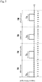
- Fig. 4 is a waveform diagram of a drive signal of the ultrasonic motor 5 according to a first control method.
- Fig. 5 is a waveform diagram of a drive signal of the ultrasonic motor 5 according to a second control method.
- the control unit 23 fixes the control cycles TM of the ultrasonic motor 5 based on a clock signal from the clock signal oscillation unit 63 and changes the ratio of the acceleration period Ta in each control cycle TM (the acceleration period Ta is started once in the control cycle TM). Thereafter, the control unit 23 sets 0th to k-1-th sections by dividing the control cycle TM by k (k is a natural number not less than 2), and regularly shifts the time to start the acceleration period Ta for each cycle.
- 0th, 1st, 2nd, 3rd, 4th, 5th, 6th, and 7th sections are set by equally dividing the control cycle TM into the eight sections.
- the control unit 23 shifts the time to start the acceleration period Ta by one section for each cycle.
- the time to start the acceleration period Ta is shifted by a predetermined time for each cycle so that the acceleration period Ta is started from the beginning of the 0th section in the first cycle, the acceleration period Ta is started from the beginning of the 1st section in the second cycle, the acceleration period Ta is started from the beginning of the 2nd section in the third cycle, and the acceleration period Ta is started from the beginning of the 3rd section in the fourth cycle.
- the acceleration period Ta may be started from a section other than the 0th section, or may be started at the end of a section or an intermediate point of a section.
- the starting time of the acceleration period Ta is changed for each cycle, so that generation of harmonics can be suppressed and noise sounding during low-speed rotation can be reduced.
- Fig. 6 is a waveform diagram of a drive signal of the ultrasonic motor according to a third control method, and is another example of a method for regularly shifting the starting time of the acceleration period Ta for each cycle.
- the same components as in the second control method are designated by the same reference numerals, and description thereof is omitted. As shown in Fig.
- the control unit 23 starts the acceleration period Ta from the beginning of the 0th section in the n-th cycle (n is a natural number), starts the acceleration period Ta from the beginning of the fourth section in the n+1-th cycle, starts the acceleration period Ta from the beginning of the fourth section in the n+2-th cycle, and starts the acceleration period Ta from the beginning of the 0th section in the n+3-th cycle, and repeats this process. That is, the control unit 23 regularly shifts the starting time of the acceleration period Ta to the sections
- the regularity shown in Fig. 6 is an example, and other than this, it is only required to make a certain rule (regularity) such as shifting to even-numbered sections such as
- a certain rule such as shifting to even-numbered sections such as
- the section to start the acceleration period Ta is regularly shifted for each cycle, the starting time of the acceleration period is changed for each period, so that generation of harmonics is suppressed, and noise sounding during low-speed rotation can be reduced.
- the interval of starting the acceleration period Ta changes periodically in such a manner that the interval is from the 0th section to the 4th section in the cycles from the n-th cycle to the n+1-th cycle, the interval is from the 4th section to the 4th section in the cycles from the n+1-th cycle to the n+2-th cycle, the interval is from the 4th section to the 0th section in the cycles from the n+2-th cycle to the n+3-th cycle, and the interval is from the 0th section to the 0th section in the cycles from the n+3-th cycle to the n+4-th cycle, so that the acceleration can be varied to increase and decrease.
- Fig. 7 is a waveform diagram of a drive signal of the ultrasonic motor 5 according to a fourth control method.
- the control unit 23 fixes the control cycles TM of the ultrasonic motor 5 based on a clock signal from the clock signal oscillation unit 63, and changes a ratio of an acceleration period Ta in each control cycle TM (the acceleration period Ta is started once in one control cycle TM). Thereafter, the control unit 23 alternately repeats second-half acceleration control Col(r) to end the acceleration period Ta so that it includes a terminal end of the control cycle TM and first-half acceleration control Col(f) to start the acceleration period Ta so that it includes a starting end of the control cycle TM for each cycle.
- the acceleration period Ta in the second-half acceleration control Col(r) and the acceleration period Ta in the first-half acceleration control Col (f) become successive, so that in the present embodiment, the drive signal apparently rises once in a cycle (hereinafter, referred to as an apparent cycle TM') two times as long as the control cycle TM.
- an apparent cycle TM' the drive signal apparently rises once in a cycle (hereinafter, referred to as an apparent cycle TM') two times as long as the control cycle TM.
- an apparent cycle TM' 8 msec.
- the control cycle TM remains as 4 msec, so that the acceleration period Ta can be made different by the second-half acceleration control Col (r) and the first-half acceleration control Col(f).
- the acceleration period Ta in the first-half acceleration control Col(f) can be changed to 1.3 msec. That is, while leaving the feedback control as it is (4 msec), the interval of the drive signal doubles (8 msec), so that noise sounding can be reduced without deteriorating the tracking performance.
- the first cycle in the fourth control method may be started from the first-half acceleration control Col(f).
- the last cycle in the control may be ended in the second-half acceleration control Col(r).
- the fourth control method can be regarded as a kind of method for "regularly shifting the starting time of the acceleration period Ta for each cycle" as the second and third control methods.
- the fourth control method when 0th to 7th sections are set by equally dividing the control cycle TM into the eight sections, the section to start the acceleration period Ta is regularly shifted for each cycle to
Landscapes
- Physics & Mathematics (AREA)
- Engineering & Computer Science (AREA)
- General Physics & Mathematics (AREA)
- Radar, Positioning & Navigation (AREA)
- Remote Sensing (AREA)
- Electromagnetism (AREA)
- Mechanical Engineering (AREA)
- General Electrical Machinery Utilizing Piezoelectricity, Electrostriction Or Magnetostriction (AREA)
Abstract
Description
- The present invention relates to a method for controlling an ultrasonic motor that drives a rotary shaft of a surveying instrument, and a surveying instrument for the same.
- A surveying instrument, for example, a total station includes a telescope that collimates a measurement point, a bracket portion that supports the telescope rotatably in the vertical direction, and a base that supports the bracket portion rotatably in the horizontal direction. The telescope is driven by a vertical rotary motor provided on a vertical rotary shaft, and the bracket portion is driven by a horizontal rotary motor provided on a horizontal rotary shaft.
Patent Document 1 discloses a surveying instrument adopting ultrasonic motors as the vertical rotary motor and the horizontal rotary motor. - [Patent Document 1] Japanese Published Unexamined Patent Application No.
2014-137299 - Many surveying instruments have an automatic tracking mode for automatically tracking a moving target. In an automatic tracking mode, in order to track a target that an operator carries, low-speed rotation at approximately 5 [°/sec] is necessary. An ultrasonic motor hardly rotates at a low speed during continuous driving, and at the time of low-speed rotation, intermittent driving in which a drive signal is turned ON/OFF is performed as shown in
Fig. 8 . That is, in a predetermined control cycle TM, an acceleration period Ta in which a drive signal is applied and a deceleration period Tr in which the drive signal is stopped are provided, and by changing the ratio of the acceleration period Ta and the deceleration period Tr, an average speed in the control cycle TM is controlled. - However, when intermittent driving is performed, at a rise and a fall of the drive signal, that is, at the start and the end of the acceleration period Ta, abnormal noise sounds, and this is unpleasant to the ears as compared with the time of continuous driving.
- In order to solve the above-described problem, an object of the present invention is to provide a method for controlling an ultrasonic motor to reduce noise sounding during low-speed rotation in a surveying instrument adopting the ultrasonic motor for a rotary shaft, and a surveying instrument for the same.
- In order to solve the above-described problem, a method for controlling an ultrasonic motor according to an aspect of the present invention is a method for controlling an ultrasonic motor that drives a rotary shaft of a surveying instrument in response to a drive signal, wherein in a low-speed rotation range of the ultrasonic motor, a ratio of an acceleration period as a time of application of the drive signal in a control cycle is controlled, and a time to start the acceleration period is randomly shifted for each control cycle.
- A method for controlling an ultrasonic motor according to another aspect is a method for controlling an ultrasonic motor that drives a rotary shaft of a surveying instrument in response to a drive signal, wherein in a low-speed rotation range of the ultrasonic motor, a ratio of an acceleration period as a time of application of the drive signal in a control cycle is controlled, and a time to start the acceleration period is regularly shifted for each control cycle.
- In the above-described aspect, it is also preferable that a certain time within the control cycle is set as a starting point and the time to start the acceleration period is shifted by a fixed time from the starting point for each control cycle.
- In the above-described aspect, it is also preferable that 0th to k-1-th sections are set by dividing the control cycle by k (k is a natural number not less than 2), the time to start the acceleration period is set in any of the sections, and the section is regularly shifted for each control cycle.
- A method for controlling an ultrasonic motor according to still another aspect is a method for controlling an ultrasonic motor that drives a rotary shaft of a surveying instrument in response to a drive signal, wherein in a low-speed rotation range of the ultrasonic motor, a ratio of an acceleration period as a time of application of the drive signal in a control cycle is controlled, and second-half acceleration control to end the acceleration period in each control cycle so that the acceleration period includes a terminal end of the control cycle, and first-half acceleration control to start the acceleration period so that the acceleration period includes a starting end of the control cycle, are alternately repeated.
- A surveying instrument according to an aspect of the present invention includes a rotary shaft, an ultrasonic motor that drives the rotary shaft in response to a drive signal, an encoder that detects a rotation speed of the rotary shaft, and a control unit that executes any of the control methods described above.
- The present invention provides a method for controlling an ultrasonic motor to reduce noise sounding during low-speed rotation in a surveying instrument adopting the ultrasonic motor for a rotary shaft, and a surveying instrument for the same.
-
-
Fig. 1 is a schematic longitudinal sectional view of a surveying instrument according to the present embodiment. -
Fig. 2 is a sectional perspective view of a portion including an ultrasonic motor shown inFig. 1 . -
Fig. 3 is a control block diagram of the surveying instrument according to the present embodiment. -
Fig. 4 is a waveform diagram of a drive signal of an ultrasonic motor according to a first control method. -
Fig. 5 is a waveform diagram of a drive signal of an ultrasonic motor according to a second control method. -
Fig. 6 is a waveform diagram of a drive signal of an ultrasonic motor according to a third control method. -
Fig. 7 is a waveform diagram of a drive signal of an ultrasonic motor according to a fourth control method. -
Fig. 8 is a control image diagram in which an ultrasonic motor is intermittently driven. - Next, a preferred embodiment of the present invention is described with reference to the drawings.
-
Fig. 1 is a schematic longitudinal sectional view of a surveying instrument according to the present embodiment, andFig. 2 is a sectional perspective view of a portion including an ultrasonic motor shown inFig. 1 . Thereference numeral 1 denotes a surveying instrument, and thesurveying instrument 1 includes abase 4 provided on aleveling portion 3, abracket portion 7 that rotates horizontally around a horizontalrotary shaft 6 on thebase 4, and a telescope 9 that is supported by thebracket portion 7 and rotates vertically around a verticalrotary shaft 11. In thebracket portion 7, acontrol unit 23 is housed. Thesurveying instrument 1 has an automatic collimation function and an automatic tracking function, and the telescope 9 houses a range-finding optical system and a tracking optical system that are not shown. Configurations of the range-finding optical system and the tracking optical system may be equivalent to those of conventional technologies, so that description thereof is omitted. In thesurveying instrument 1, range-finding light and tracking light are irradiated onto a target by collaboration between horizontal rotation of thebracket portion 7 and vertical rotation of the telescope 9. - At a lower end portion of the horizontal
rotary shaft 6, anultrasonic motor 5 for horizontal rotation is provided, and at an upper end portion, anencoder 21 to detect a horizontal angle is provided. At one end portion of the verticalrotary shaft 11, anultrasonic motor 12 for vertical rotation is provided, and at the other end portion, anencoder 22 to detect a vertical angle is provided. Theencoders - Concerning configurations of the
ultrasonic motors ultrasonic motor 5 includes, in a ring form, in order from abase portion 39, a piezoelectric ceramic 42 that generates vibration, astator 43 that amplifies vibration, arotor 46 that interferes with thestator 43, and awave washer 48 that presses therotor 46 toward thestator 43 side. To the piezoelectric ceramic 42, a Sin electrode and a Cos electrode are attached, and when a drive voltage is alternately applied to these electrodes, the piezoelectric ceramic 42 ultrasonically vibrates. When the piezoelectric ceramic 42 vibrates, a wavelike traveling wave is formed in thestator 43, and due to friction caused by pressing of thewave washer 48, thestator 43 and therotor 46 rotate relative to each other. As shown inFig. 1 , in the horizontalultrasonic motor 5, amotor case 25 is fixed to thebase 4 and arotor 46 is fixed to themotor case 25, so that when thestator 43 rotates, the horizontalrotary shaft 6 rotates integrally with thestator 43 via thebase portion 39. In the verticalultrasonic motor 12, astator 43 is fixed to amotor case 25, and when arotor 46 rotates, the verticalrotary shaft 11 rotates integrally with therotor 46. -
Fig. 3 is a control block diagram of thesurveying instrument 1. Block diagrams of vertical rotation and horizontal rotation are equivalent to each other, so that the horizontal rotation is shown, and description on the vertical rotation is omitted. Thesurveying instrument 1 includes acontrol unit 23, anencoder 21, a range-finding unit 61, atracking unit 62, a clocksignal oscillation unit 63, adrive circuit 73, and theultrasonic motor 5. - The
control unit 23 is configured with a microcontroller including a CPU, a ROM, and a RAM, etc., mounted on an integrated circuit. Software of thecontrol unit 23 is changeable from an external personal computer that is not shown. Thecontrol unit 23 successively obtains a rotation speed of therotary shaft 6 from an angle signal of theencoder 21. In addition, the control unit outputs a drive signal to theultrasonic motor 5 via thedrive circuit 73. A waveform of this drive signal is described in detail below. - The range-
finding unit 61 irradiates, under control by thecontrol unit 23, a target with range-finding light by using the range-finding optical system, captures the target by light reflected thereon, and performs automatic collimation. When manual or automatic collimation is completed, the range-finding unit performs range-finding. Thetracking unit 62 irradiates, under control by thecontrol unit 23, a target with tracking light by using the tracking optical system and captures the target by light reflected thereon, and automatically tracks the target when the target moves. - The
drive circuit 73 includes an FPGA (Field Programmable Gate Array) 731 and ananalog circuit 732. Definition of an internal logic circuit of theFPGA 731 can be changed by thecontrol unit 23 or an external device not shown. TheFPGA 731 can generate a control signal at a variable drive frequency (drive signal frequency) and a variable amplitude, and can dynamically change the drive frequency and the amplitude. Theanalog circuit 732 includes a transformer, etc., and amplifies the control signal. Thedrive circuit 73 outputs the control signal from theFPGA 731 in response to a command from thecontrol unit 23, and amplifies the control signal by theanalog circuit 732 to generate two kinds of drive signals with different phases, and outputs these to the Sin electrode and the Cos electrode attached to thepiezoelectric ceramic 42 of theultrasonic motor 5. For thedrive circuit 73, other PLDs (Programmable Logic Devices) such as an ASIC (Application Specific Integrated Circuit) may be used. - The clock
signal oscillation unit 63 outputs a clock signal to thecontrol unit 23 and theFPGA 731. Thecontrol unit 23 controls a light emitting cycle of theencoder 21 based on the clock signal. TheFPGA 731 controls, based on the clock signal, the amplitude of the drive signal, the drive frequency f, and control cycles TM of the drive signal, and in a low-speed rotation range, controls a ratio of an acceleration period Ta (time of application of the drive signal) and a deceleration period Tr (time of stoppage of the drive signal) in the control cycle TM. In the present specification, the low-speed rotation range means a speed range in which the ultrasonic motor is not continuously driven to rotate. This low-speed rotation range differs among individual ultrasonic motors depending on the manufacturing states thereof, so that the low-speed rotation range is defined in advance in thecontrol unit 23 by investigating the characteristics of the ultrasonic motor to be adopted. - By using the above-described configuration, the
control unit 23 of the surveyinginstrument 1 controls the drive signal as follows in the low-speed rotation range of theultrasonic motor 5. Although description on the vertical rotation is also omitted below, the same control as in the case of horizontal rotation is performed for the vertical rotation. -
Fig. 4 is a waveform diagram of a drive signal of theultrasonic motor 5 according to a first control method. While referring to a rotation speed of therotary shaft 6, thecontrol unit 23 fixes control cycles TM of theultrasonic motor 5 based on a clock signal from the clocksignal oscillation unit 63 and changes a ratio of an acceleration period Ta in each control cycle TM (ratio of an acceleration period Ta and a deceleration period Tr, the acceleration period Ta is started once in the control cycle TM). Thereafter, thecontrol unit 23 sets randomly a time to start the acceleration period Ta for each cycle. That is, the acceleration period Ta in the control cycle TM is started from a time different for each cycle based on the clock signal (for example, 1 pulse = 1 µsec as a minimum unit). - As in a conventional case, that is, as shown in
Fig. 8 , when the acceleration period Ta is started from the same time in each cycle, for example, when the control cycle TM = 4 msec, a spectrum with a frequency of 250 kHz equivalent to 4 msec and its harmonics of 500 kHz and 1000 kHz is observed. This causes abnormal noise to be felt. - On the other hand, by randomly shifting the time to start the acceleration period Ta for each cycle, generation of harmonics is suppressed, and noise sounding during low-speed rotation can be reduced.
-
Fig. 5 is a waveform diagram of a drive signal of theultrasonic motor 5 according to a second control method. While referring to a rotation speed of therotary shaft 6, thecontrol unit 23 fixes the control cycles TM of theultrasonic motor 5 based on a clock signal from the clocksignal oscillation unit 63 and changes the ratio of the acceleration period Ta in each control cycle TM (the acceleration period Ta is started once in the control cycle TM). Thereafter, thecontrol unit 23 sets 0th to k-1-th sections by dividing the control cycle TM by k (k is a natural number not less than 2), and regularly shifts the time to start the acceleration period Ta for each cycle. - As an example, in
Fig. 5 , 0th, 1st, 2nd, 3rd, 4th, 5th, 6th, and 7th sections are set by equally dividing the control cycle TM into the eight sections. In this case, thecontrol unit 23 shifts the time to start the acceleration period Ta by one section for each cycle. For example, the time to start the acceleration period Ta is shifted by a predetermined time for each cycle so that the acceleration period Ta is started from the beginning of the 0th section in the first cycle, the acceleration period Ta is started from the beginning of the 1st section in the second cycle, the acceleration period Ta is started from the beginning of the 2nd section in the third cycle, and the acceleration period Ta is started from the beginning of the 3rd section in the fourth cycle. After the starting time reaches the 7th section, it may be turned back to the 6th section, or returned to the 0th section again. Alternatively, the acceleration period Ta may be started from a section other than the 0th section, or may be started at the end of a section or an intermediate point of a section. - Thus, by regularly shifting the section to start the acceleration period Ta for each cycle, the starting time of the acceleration period Ta is changed for each cycle, so that generation of harmonics can be suppressed and noise sounding during low-speed rotation can be reduced.
-
Fig. 6 is a waveform diagram of a drive signal of the ultrasonic motor according to a third control method, and is another example of a method for regularly shifting the starting time of the acceleration period Ta for each cycle. The same components as in the second control method are designated by the same reference numerals, and description thereof is omitted. As shown inFig. 5 , after setting 0th to 7th sections by equally dividing the control cycle TM into the eight sections, thecontrol unit 23 starts the acceleration period Ta from the beginning of the 0th section in the n-th cycle (n is a natural number), starts the acceleration period Ta from the beginning of the fourth section in the n+1-th cycle, starts the acceleration period Ta from the beginning of the fourth section in the n+2-th cycle, and starts the acceleration period Ta from the beginning of the 0th section in the n+3-th cycle, and repeats this process. That is, thecontrol unit 23 regularly shifts the starting time of the acceleration period Ta to the sections | 0, 4, 4, 0 | 0, 4, 4, 0|.... - The regularity shown in
Fig. 6 is an example, and other than this, it is only required to make a certain rule (regularity) such as shifting to even-numbered sections such as |0, 2, 4, 6| , shifting to odd-numbered sections such as |1, 3, 5, 7|, and shifting alternately to even-numbered and odd-numbered sections such as | 0, 2, 4, 6|1, 3, 5, 7|..., shifting by three sections, or starting from a section selected among rearranged arbitrary three sections or a combination of arbitrary three sections, etc. - Thus, even when the section to start the acceleration period Ta is regularly shifted for each cycle, the starting time of the acceleration period is changed for each period, so that generation of harmonics is suppressed, and noise sounding during low-speed rotation can be reduced.
- In the example shown in
Fig. 6 , the interval of starting the acceleration period Ta changes periodically in such a manner that the interval is from the 0th section to the 4th section in the cycles from the n-th cycle to the n+1-th cycle, the interval is from the 4th section to the 4th section in the cycles from the n+1-th cycle to the n+2-th cycle, the interval is from the 4th section to the 0th section in the cycles from the n+2-th cycle to the n+3-th cycle, and the interval is from the 0th section to the 0th section in the cycles from the n+3-th cycle to the n+4-th cycle, so that the acceleration can be varied to increase and decrease. - As a method for regularly shifting the starting time of the acceleration period Ta for each cycle, not only the method in which the control cycle TM is divided by k but also a method in which the starting time is shifted by a predetermined time for each cycle based on a clock signal can be adopted. For example, it is also possible that by setting 1 pulse = 1 µsec as a minimum unit, the starting time of the acceleration period Ta is shifted by 1 µsec for each cycle, and after the starting time reaches a terminal end of a control cycle TM, it may be turned back or returned to a starting end of a control cycle TM.
-
Fig. 7 is a waveform diagram of a drive signal of theultrasonic motor 5 according to a fourth control method. Thecontrol unit 23 fixes the control cycles TM of theultrasonic motor 5 based on a clock signal from the clocksignal oscillation unit 63, and changes a ratio of an acceleration period Ta in each control cycle TM (the acceleration period Ta is started once in one control cycle TM). Thereafter, thecontrol unit 23 alternately repeats second-half acceleration control Col(r) to end the acceleration period Ta so that it includes a terminal end of the control cycle TM and first-half acceleration control Col(f) to start the acceleration period Ta so that it includes a starting end of the control cycle TM for each cycle. - Thus, by alternately repeating the second-half acceleration control Col(r) and the first-half acceleration control Col (f), the acceleration period Ta in the second-half acceleration control Col(r) and the acceleration period Ta in the first-half acceleration control Col (f) become successive, so that in the present embodiment, the drive signal apparently rises once in a cycle (hereinafter, referred to as an apparent cycle TM') two times as long as the control cycle TM. For example, when the control cycle TM = 4 msec, one acceleration period Ta is provided in an apparent cycle TM' = 8 msec. Therefore, the number of turning ON/OFF of the drive signal becomes half as many as that in the case of the control cycle TM = 4 msec, and a frequency spectrum becomes 125 kHz equivalent to 8 msec of the apparent cycle TM' . Therefore, the noise sound becomes lower in frequency than in the case of 4 msec, so that unpleasant noise to the ears is significantly reduced.
- In the fourth control method, the control cycle TM remains as 4 msec, so that the acceleration period Ta can be made different by the second-half acceleration control Col (r) and the first-half acceleration control Col(f). For example, when the acceleration period Ta is 1 msec in the second-half acceleration control Col(r), when it is desired to increase the rotation speed, the acceleration period Ta in the first-half acceleration control Col(f) can be changed to 1.3 msec. That is, while leaving the feedback control as it is (4 msec), the interval of the drive signal doubles (8 msec), so that noise sounding can be reduced without deteriorating the tracking performance.
- The first cycle in the fourth control method may be started from the first-half acceleration control Col(f). The last cycle in the control may be ended in the second-half acceleration control Col(r).
- The fourth control method can be regarded as a kind of method for "regularly shifting the starting time of the acceleration period Ta for each cycle" as the second and third control methods. In the fourth control method, when 0th to 7th sections are set by equally dividing the control cycle TM into the eight sections, the section to start the acceleration period Ta is regularly shifted for each cycle to |7, 0, 7, 0 |7, 0, 7, 0 |.... That is, the fourth control method is a method for regularly shifting the starting time of the acceleration period Ta to |k-1, 0, k-1, 0 ... when the control cycle TM is divided by k.
- Preferred embodiments and modifications are described above, and it is possible to combine the embodiments and modifications based on knowledge of a person skilled in the art. For example, the amplitude of the drive signal is fixed in the embodiments and modifications described above, however, the amplitude may be changed for each cycle. Such alteration is also included in the scope of the present invention.
-
- 1
- Surveying instrument
- 5, 12
- Ultrasonic motor
- 6, 11
- Rotary shaft
- 21, 22
- Encoder
- 23
- Control unit
- TM
- Control cycle
- Ta
- Acceleration period
- Col(r)
- Second-half acceleration control
- Col(f)
- First-half acceleration control
Claims (6)
- A method for controlling an ultrasonic motor that drives a rotary shaft of a surveying instrument in response to a drive signal, whereinin a low-speed rotation range of the ultrasonic motor, a ratio of an acceleration period as a time of application of the drive signal in a control cycle is controlled, and a time to start the acceleration period is randomly shifted for each control cycle.
- A method for controlling an ultrasonic motor that drives a rotary shaft of a surveying instrument in response to a drive signal, wherein
in a low-speed rotation range of the ultrasonic motor, a ratio of an acceleration period as a time of application of the drive signal in a control cycle is controlled, and a time to start the acceleration period is regularly shifted for each control cycle. - The method for controlling an ultrasonic motor according to Claim 2, wherein a certain time within the control cycle is set as a starting point and the time to start the acceleration period is shifted by a fixed time from the starting point for each control cycle.
- The method for controlling an ultrasonic motor according to Claim 2, wherein
0th to k-1-th sections are set by dividing the control cycle by k (k is a natural number not less than 2), the time to start the acceleration period is set in any of the sections, and the section is regularly shifted for each control cycle. - A method for controlling an ultrasonic motor that drives a rotary shaft of a surveying instrument in response to a drive signal, wherein
in a low-speed rotation range of the ultrasonic motor, a ratio of an acceleration period as a time of application of the drive signal in a control cycle is controlled, and second-half acceleration control to end the acceleration period in each control cycle so that the acceleration period includes a terminal end of the control cycle, and first-half acceleration control to start the acceleration period so that the acceleration period includes a starting end of the control cycle, are alternately repeated. - A surveying instrument comprising:a rotary shaft;an ultrasonic motor that drives the rotary shaft in response to a drive signal;an encoder that detects a rotation speed of the rotary shaft; anda control unit that executes any of the control methods described in Claims 1 to 5.
Applications Claiming Priority (1)
| Application Number | Priority Date | Filing Date | Title |
|---|---|---|---|
| JP2016087805A JP6707394B2 (en) | 2016-04-26 | 2016-04-26 | Control method of ultrasonic motor and surveying instrument therefor |
Publications (2)
| Publication Number | Publication Date |
|---|---|
| EP3240181A1 true EP3240181A1 (en) | 2017-11-01 |
| EP3240181B1 EP3240181B1 (en) | 2020-12-16 |
Family
ID=58544808
Family Applications (1)
| Application Number | Title | Priority Date | Filing Date |
|---|---|---|---|
| EP17166053.3A Active EP3240181B1 (en) | 2016-04-26 | 2017-04-11 | Control of ultrasonic motor in surveying instrument |
Country Status (3)
| Country | Link |
|---|---|
| US (1) | US10211387B2 (en) |
| EP (1) | EP3240181B1 (en) |
| JP (1) | JP6707394B2 (en) |
Families Citing this family (4)
| Publication number | Priority date | Publication date | Assignee | Title |
|---|---|---|---|---|
| JP6650726B2 (en) * | 2015-10-20 | 2020-02-19 | 株式会社トプコン | measuring device |
| JP6650727B2 (en) | 2015-10-20 | 2020-02-19 | 株式会社トプコン | Tilt angle measuring device |
| JP6691419B2 (en) * | 2016-04-15 | 2020-04-28 | 株式会社トプコン | Control method of ultrasonic motor and surveying instrument therefor |
| US11064097B2 (en) * | 2018-11-01 | 2021-07-13 | Canon Kabushiki Kaisha | Imaging apparatus for adjusting pressing forces of an ultrasonic motor and a waterproof member |
Citations (4)
| Publication number | Priority date | Publication date | Assignee | Title |
|---|---|---|---|---|
| US4692672A (en) * | 1984-02-10 | 1987-09-08 | Canon Kabushiki Kaisha | Vibration wave motor |
| JPH0789748B2 (en) * | 1986-10-28 | 1995-09-27 | 松下電器産業株式会社 | Ultrasonic motor drive method |
| JP2014137299A (en) | 2013-01-17 | 2014-07-28 | Topcon Corp | Rotary drive section of survey instrument, and survey instrument |
| DE202014008041U1 (en) * | 2014-10-10 | 2014-11-03 | Leica Geosystems Ag | Surveyor with traveling wave drive |
Family Cites Families (8)
| Publication number | Priority date | Publication date | Assignee | Title |
|---|---|---|---|---|
| US3886459A (en) * | 1973-08-07 | 1975-05-27 | Usm Corp | Digital pulse rate ramping circuits |
| US3838325A (en) * | 1973-08-30 | 1974-09-24 | K Kobayashi | Motor speed acceleration-deceleration control circuit |
| HU179165B (en) * | 1976-12-06 | 1982-08-28 | Epitoegepgyarto Vallalat | Method and circuit array of controlling current convrters,preferably for continuous speed-control of a.c. motors |
| US4297628A (en) * | 1980-07-03 | 1981-10-27 | Louis W. Parker | Energy economizer for induction motors |
| JP4465671B2 (en) * | 1999-07-19 | 2010-05-19 | 株式会社トプコン | Electronic surveying instrument |
| US6433507B1 (en) * | 2000-02-18 | 2002-08-13 | Siemens Automotive Inc. | Spread spectrum motor control circuit |
| US6674962B2 (en) * | 2002-01-29 | 2004-01-06 | Siemens Vdo Automotive, Inc. | Limited-pool random frequency for DC brush motor low frequency PWM speed control |
| JP4894308B2 (en) * | 2006-03-13 | 2012-03-14 | コニカミノルタオプト株式会社 | Drive device |
-
2016
- 2016-04-26 JP JP2016087805A patent/JP6707394B2/en active Active
-
2017
- 2017-03-20 US US15/463,920 patent/US10211387B2/en active Active
- 2017-04-11 EP EP17166053.3A patent/EP3240181B1/en active Active
Patent Citations (5)
| Publication number | Priority date | Publication date | Assignee | Title |
|---|---|---|---|---|
| US4692672A (en) * | 1984-02-10 | 1987-09-08 | Canon Kabushiki Kaisha | Vibration wave motor |
| JPH0789748B2 (en) * | 1986-10-28 | 1995-09-27 | 松下電器産業株式会社 | Ultrasonic motor drive method |
| JP2014137299A (en) | 2013-01-17 | 2014-07-28 | Topcon Corp | Rotary drive section of survey instrument, and survey instrument |
| EP2759801A2 (en) * | 2013-01-17 | 2014-07-30 | Kabushiki Kaisha Topcon | Rotary drive unit of a surveying instrument and a surveying instrument |
| DE202014008041U1 (en) * | 2014-10-10 | 2014-11-03 | Leica Geosystems Ag | Surveyor with traveling wave drive |
Also Published As
| Publication number | Publication date |
|---|---|
| US10211387B2 (en) | 2019-02-19 |
| EP3240181B1 (en) | 2020-12-16 |
| JP2017200274A (en) | 2017-11-02 |
| US20170309806A1 (en) | 2017-10-26 |
| JP6707394B2 (en) | 2020-06-10 |
Similar Documents
| Publication | Publication Date | Title |
|---|---|---|
| EP3240181B1 (en) | Control of ultrasonic motor in surveying instrument | |
| JP5679781B2 (en) | Control device for vibration actuator | |
| EP1416250A3 (en) | Z-axis vibration gyroscope | |
| JP4894308B2 (en) | Drive device | |
| JP2012115102A5 (en) | ||
| CN103715940A (en) | Driving unit of a vibration-type actuator | |
| KR20000069890A (en) | Method and device for controlling a stepping motor | |
| JPH0690574A (en) | Ultrasonic motor and electronic equipment with ultrasonic motor | |
| KR20200141001A (en) | Smart power toothbrush | |
| EP3232560B1 (en) | Control of ultrasonic motor in surveying instrument | |
| JP2003021780A (en) | Camera apparatus | |
| JP4825661B2 (en) | Vibration generator | |
| JP6615653B2 (en) | Surveying instrument | |
| JP6669538B2 (en) | Control method of ultrasonic motor provided in surveying instrument and surveying instrument therefor | |
| JP6608743B2 (en) | Ultrasonic motor control method and surveying instrument therefor | |
| KR101944139B1 (en) | Device for determining the angular velocity or velocity and the direction of motion | |
| JPH05336762A (en) | Drive control circuit for ultrasonic motor | |
| JP2004201405A (en) | Method and apparatus for controlling speed and displacement of movable body driven by ultrasonic motor | |
| JP2874796B2 (en) | Control device for vibration actuator | |
| JP2007074787A (en) | Drive device and drive method for vibration actuator | |
| JP2003107389A (en) | Scanner driver, scanner and three-dimensional measurement device | |
| JP5403947B2 (en) | Drive device and control method of drive device | |
| JP6615671B2 (en) | Ultrasonic motor control method and surveying instrument therefor | |
| JPH0241674A (en) | Oscillating wave motor | |
| JP2821807B2 (en) | Ultrasonic motor drive controller |
Legal Events
| Date | Code | Title | Description |
|---|---|---|---|
| PUAI | Public reference made under article 153(3) epc to a published international application that has entered the european phase |
Free format text: ORIGINAL CODE: 0009012 |
|
| STAA | Information on the status of an ep patent application or granted ep patent |
Free format text: STATUS: THE APPLICATION HAS BEEN PUBLISHED |
|
| AK | Designated contracting states |
Kind code of ref document: A1 Designated state(s): AL AT BE BG CH CY CZ DE DK EE ES FI FR GB GR HR HU IE IS IT LI LT LU LV MC MK MT NL NO PL PT RO RS SE SI SK SM TR |
|
| AX | Request for extension of the european patent |
Extension state: BA ME |
|
| STAA | Information on the status of an ep patent application or granted ep patent |
Free format text: STATUS: REQUEST FOR EXAMINATION WAS MADE |
|
| 17P | Request for examination filed |
Effective date: 20180417 |
|
| RBV | Designated contracting states (corrected) |
Designated state(s): AL AT BE BG CH CY CZ DE DK EE ES FI FR GB GR HR HU IE IS IT LI LT LU LV MC MK MT NL NO PL PT RO RS SE SI SK SM TR |
|
| STAA | Information on the status of an ep patent application or granted ep patent |
Free format text: STATUS: EXAMINATION IS IN PROGRESS |
|
| 17Q | First examination report despatched |
Effective date: 20190920 |
|
| GRAP | Despatch of communication of intention to grant a patent |
Free format text: ORIGINAL CODE: EPIDOSNIGR1 |
|
| STAA | Information on the status of an ep patent application or granted ep patent |
Free format text: STATUS: GRANT OF PATENT IS INTENDED |
|
| GRAS | Grant fee paid |
Free format text: ORIGINAL CODE: EPIDOSNIGR3 |
|
| INTG | Intention to grant announced |
Effective date: 20201012 |
|
| GRAA | (expected) grant |
Free format text: ORIGINAL CODE: 0009210 |
|
| STAA | Information on the status of an ep patent application or granted ep patent |
Free format text: STATUS: THE PATENT HAS BEEN GRANTED |
|
| AK | Designated contracting states |
Kind code of ref document: B1 Designated state(s): AL AT BE BG CH CY CZ DE DK EE ES FI FR GB GR HR HU IE IS IT LI LT LU LV MC MK MT NL NO PL PT RO RS SE SI SK SM TR |
|
| REG | Reference to a national code |
Ref country code: GB Ref legal event code: FG4D |
|
| REG | Reference to a national code |
Ref country code: DE Ref legal event code: R096 Ref document number: 602017029498 Country of ref document: DE |
|
| REG | Reference to a national code |
Ref country code: IE Ref legal event code: FG4D |
|
| REG | Reference to a national code |
Ref country code: AT Ref legal event code: REF Ref document number: 1346509 Country of ref document: AT Kind code of ref document: T Effective date: 20210115 |
|
| REG | Reference to a national code |
Ref country code: CH Ref legal event code: NV Representative=s name: VALIPAT S.A. C/O BOVARD SA NEUCHATEL, CH |
|
| PG25 | Lapsed in a contracting state [announced via postgrant information from national office to epo] |
Ref country code: RS Free format text: LAPSE BECAUSE OF FAILURE TO SUBMIT A TRANSLATION OF THE DESCRIPTION OR TO PAY THE FEE WITHIN THE PRESCRIBED TIME-LIMIT Effective date: 20201216 Ref country code: NO Free format text: LAPSE BECAUSE OF FAILURE TO SUBMIT A TRANSLATION OF THE DESCRIPTION OR TO PAY THE FEE WITHIN THE PRESCRIBED TIME-LIMIT Effective date: 20210316 Ref country code: FI Free format text: LAPSE BECAUSE OF FAILURE TO SUBMIT A TRANSLATION OF THE DESCRIPTION OR TO PAY THE FEE WITHIN THE PRESCRIBED TIME-LIMIT Effective date: 20201216 Ref country code: GR Free format text: LAPSE BECAUSE OF FAILURE TO SUBMIT A TRANSLATION OF THE DESCRIPTION OR TO PAY THE FEE WITHIN THE PRESCRIBED TIME-LIMIT Effective date: 20210317 |
|
| REG | Reference to a national code |
Ref country code: AT Ref legal event code: MK05 Ref document number: 1346509 Country of ref document: AT Kind code of ref document: T Effective date: 20201216 |
|
| REG | Reference to a national code |
Ref country code: NL Ref legal event code: MP Effective date: 20201216 |
|
| PG25 | Lapsed in a contracting state [announced via postgrant information from national office to epo] |
Ref country code: SE Free format text: LAPSE BECAUSE OF FAILURE TO SUBMIT A TRANSLATION OF THE DESCRIPTION OR TO PAY THE FEE WITHIN THE PRESCRIBED TIME-LIMIT Effective date: 20201216 Ref country code: BG Free format text: LAPSE BECAUSE OF FAILURE TO SUBMIT A TRANSLATION OF THE DESCRIPTION OR TO PAY THE FEE WITHIN THE PRESCRIBED TIME-LIMIT Effective date: 20210316 Ref country code: LV Free format text: LAPSE BECAUSE OF FAILURE TO SUBMIT A TRANSLATION OF THE DESCRIPTION OR TO PAY THE FEE WITHIN THE PRESCRIBED TIME-LIMIT Effective date: 20201216 |
|
| PG25 | Lapsed in a contracting state [announced via postgrant information from national office to epo] |
Ref country code: HR Free format text: LAPSE BECAUSE OF FAILURE TO SUBMIT A TRANSLATION OF THE DESCRIPTION OR TO PAY THE FEE WITHIN THE PRESCRIBED TIME-LIMIT Effective date: 20201216 Ref country code: NL Free format text: LAPSE BECAUSE OF FAILURE TO SUBMIT A TRANSLATION OF THE DESCRIPTION OR TO PAY THE FEE WITHIN THE PRESCRIBED TIME-LIMIT Effective date: 20201216 |
|
| REG | Reference to a national code |
Ref country code: LT Ref legal event code: MG9D |
|
| PG25 | Lapsed in a contracting state [announced via postgrant information from national office to epo] |
Ref country code: SK Free format text: LAPSE BECAUSE OF FAILURE TO SUBMIT A TRANSLATION OF THE DESCRIPTION OR TO PAY THE FEE WITHIN THE PRESCRIBED TIME-LIMIT Effective date: 20201216 Ref country code: RO Free format text: LAPSE BECAUSE OF FAILURE TO SUBMIT A TRANSLATION OF THE DESCRIPTION OR TO PAY THE FEE WITHIN THE PRESCRIBED TIME-LIMIT Effective date: 20201216 Ref country code: PT Free format text: LAPSE BECAUSE OF FAILURE TO SUBMIT A TRANSLATION OF THE DESCRIPTION OR TO PAY THE FEE WITHIN THE PRESCRIBED TIME-LIMIT Effective date: 20210416 Ref country code: EE Free format text: LAPSE BECAUSE OF FAILURE TO SUBMIT A TRANSLATION OF THE DESCRIPTION OR TO PAY THE FEE WITHIN THE PRESCRIBED TIME-LIMIT Effective date: 20201216 Ref country code: CZ Free format text: LAPSE BECAUSE OF FAILURE TO SUBMIT A TRANSLATION OF THE DESCRIPTION OR TO PAY THE FEE WITHIN THE PRESCRIBED TIME-LIMIT Effective date: 20201216 Ref country code: SM Free format text: LAPSE BECAUSE OF FAILURE TO SUBMIT A TRANSLATION OF THE DESCRIPTION OR TO PAY THE FEE WITHIN THE PRESCRIBED TIME-LIMIT Effective date: 20201216 Ref country code: LT Free format text: LAPSE BECAUSE OF FAILURE TO SUBMIT A TRANSLATION OF THE DESCRIPTION OR TO PAY THE FEE WITHIN THE PRESCRIBED TIME-LIMIT Effective date: 20201216 |
|
| PG25 | Lapsed in a contracting state [announced via postgrant information from national office to epo] |
Ref country code: AT Free format text: LAPSE BECAUSE OF FAILURE TO SUBMIT A TRANSLATION OF THE DESCRIPTION OR TO PAY THE FEE WITHIN THE PRESCRIBED TIME-LIMIT Effective date: 20201216 Ref country code: PL Free format text: LAPSE BECAUSE OF FAILURE TO SUBMIT A TRANSLATION OF THE DESCRIPTION OR TO PAY THE FEE WITHIN THE PRESCRIBED TIME-LIMIT Effective date: 20201216 |
|
| REG | Reference to a national code |
Ref country code: DE Ref legal event code: R097 Ref document number: 602017029498 Country of ref document: DE |
|
| PG25 | Lapsed in a contracting state [announced via postgrant information from national office to epo] |
Ref country code: IS Free format text: LAPSE BECAUSE OF FAILURE TO SUBMIT A TRANSLATION OF THE DESCRIPTION OR TO PAY THE FEE WITHIN THE PRESCRIBED TIME-LIMIT Effective date: 20210416 |
|
| PLBE | No opposition filed within time limit |
Free format text: ORIGINAL CODE: 0009261 |
|
| STAA | Information on the status of an ep patent application or granted ep patent |
Free format text: STATUS: NO OPPOSITION FILED WITHIN TIME LIMIT |
|
| PG25 | Lapsed in a contracting state [announced via postgrant information from national office to epo] |
Ref country code: IT Free format text: LAPSE BECAUSE OF FAILURE TO SUBMIT A TRANSLATION OF THE DESCRIPTION OR TO PAY THE FEE WITHIN THE PRESCRIBED TIME-LIMIT Effective date: 20201216 Ref country code: AL Free format text: LAPSE BECAUSE OF FAILURE TO SUBMIT A TRANSLATION OF THE DESCRIPTION OR TO PAY THE FEE WITHIN THE PRESCRIBED TIME-LIMIT Effective date: 20201216 |
|
| 26N | No opposition filed |
Effective date: 20210917 |
|
| PG25 | Lapsed in a contracting state [announced via postgrant information from national office to epo] |
Ref country code: DK Free format text: LAPSE BECAUSE OF FAILURE TO SUBMIT A TRANSLATION OF THE DESCRIPTION OR TO PAY THE FEE WITHIN THE PRESCRIBED TIME-LIMIT Effective date: 20201216 Ref country code: MC Free format text: LAPSE BECAUSE OF FAILURE TO SUBMIT A TRANSLATION OF THE DESCRIPTION OR TO PAY THE FEE WITHIN THE PRESCRIBED TIME-LIMIT Effective date: 20201216 |
|
| GBPC | Gb: european patent ceased through non-payment of renewal fee |
Effective date: 20210411 |
|
| PG25 | Lapsed in a contracting state [announced via postgrant information from national office to epo] |
Ref country code: LU Free format text: LAPSE BECAUSE OF NON-PAYMENT OF DUE FEES Effective date: 20210411 |
|
| REG | Reference to a national code |
Ref country code: BE Ref legal event code: MM Effective date: 20210430 |
|
| PG25 | Lapsed in a contracting state [announced via postgrant information from national office to epo] |
Ref country code: ES Free format text: LAPSE BECAUSE OF FAILURE TO SUBMIT A TRANSLATION OF THE DESCRIPTION OR TO PAY THE FEE WITHIN THE PRESCRIBED TIME-LIMIT Effective date: 20201216 Ref country code: GB Free format text: LAPSE BECAUSE OF NON-PAYMENT OF DUE FEES Effective date: 20210411 Ref country code: FR Free format text: LAPSE BECAUSE OF NON-PAYMENT OF DUE FEES Effective date: 20210430 |
|
| PG25 | Lapsed in a contracting state [announced via postgrant information from national office to epo] |
Ref country code: SI Free format text: LAPSE BECAUSE OF FAILURE TO SUBMIT A TRANSLATION OF THE DESCRIPTION OR TO PAY THE FEE WITHIN THE PRESCRIBED TIME-LIMIT Effective date: 20201216 |
|
| PG25 | Lapsed in a contracting state [announced via postgrant information from national office to epo] |
Ref country code: IE Free format text: LAPSE BECAUSE OF NON-PAYMENT OF DUE FEES Effective date: 20210411 |
|
| PG25 | Lapsed in a contracting state [announced via postgrant information from national office to epo] |
Ref country code: IS Free format text: LAPSE BECAUSE OF FAILURE TO SUBMIT A TRANSLATION OF THE DESCRIPTION OR TO PAY THE FEE WITHIN THE PRESCRIBED TIME-LIMIT Effective date: 20210416 |
|
| PG25 | Lapsed in a contracting state [announced via postgrant information from national office to epo] |
Ref country code: BE Free format text: LAPSE BECAUSE OF NON-PAYMENT OF DUE FEES Effective date: 20210430 |
|
| PG25 | Lapsed in a contracting state [announced via postgrant information from national office to epo] |
Ref country code: HU Free format text: LAPSE BECAUSE OF FAILURE TO SUBMIT A TRANSLATION OF THE DESCRIPTION OR TO PAY THE FEE WITHIN THE PRESCRIBED TIME-LIMIT; INVALID AB INITIO Effective date: 20170411 |
|
| PG25 | Lapsed in a contracting state [announced via postgrant information from national office to epo] |
Ref country code: CY Free format text: LAPSE BECAUSE OF FAILURE TO SUBMIT A TRANSLATION OF THE DESCRIPTION OR TO PAY THE FEE WITHIN THE PRESCRIBED TIME-LIMIT Effective date: 20201216 |
|
| PG25 | Lapsed in a contracting state [announced via postgrant information from national office to epo] |
Ref country code: MK Free format text: LAPSE BECAUSE OF FAILURE TO SUBMIT A TRANSLATION OF THE DESCRIPTION OR TO PAY THE FEE WITHIN THE PRESCRIBED TIME-LIMIT Effective date: 20201216 |
|
| PG25 | Lapsed in a contracting state [announced via postgrant information from national office to epo] |
Ref country code: MT Free format text: LAPSE BECAUSE OF FAILURE TO SUBMIT A TRANSLATION OF THE DESCRIPTION OR TO PAY THE FEE WITHIN THE PRESCRIBED TIME-LIMIT Effective date: 20201216 |
|
| PGFP | Annual fee paid to national office [announced via postgrant information from national office to epo] |
Ref country code: DE Payment date: 20250305 Year of fee payment: 9 |
|
| PGFP | Annual fee paid to national office [announced via postgrant information from national office to epo] |
Ref country code: CH Payment date: 20250501 Year of fee payment: 9 |
|
| PG25 | Lapsed in a contracting state [announced via postgrant information from national office to epo] |
Ref country code: TR Free format text: LAPSE BECAUSE OF FAILURE TO SUBMIT A TRANSLATION OF THE DESCRIPTION OR TO PAY THE FEE WITHIN THE PRESCRIBED TIME-LIMIT Effective date: 20201216 |