EP3239700A1 - Method for operating an x-ray device and x-ray device - Google Patents
Method for operating an x-ray device and x-ray device Download PDFInfo
- Publication number
- EP3239700A1 EP3239700A1 EP17167096.1A EP17167096A EP3239700A1 EP 3239700 A1 EP3239700 A1 EP 3239700A1 EP 17167096 A EP17167096 A EP 17167096A EP 3239700 A1 EP3239700 A1 EP 3239700A1
- Authority
- EP
- European Patent Office
- Prior art keywords
- ray
- sensors
- magnetic field
- measurement
- ray detector
- Prior art date
- Legal status (The legal status is an assumption and is not a legal conclusion. Google has not performed a legal analysis and makes no representation as to the accuracy of the status listed.)
- Granted
Links
- 238000000034 method Methods 0.000 title claims abstract description 26
- 230000005291 magnetic effect Effects 0.000 claims abstract description 22
- 238000005259 measurement Methods 0.000 claims abstract description 22
- 230000002596 correlated effect Effects 0.000 claims abstract description 3
- 238000013519 translation Methods 0.000 claims description 9
- 230000006870 function Effects 0.000 claims description 7
- 230000001133 acceleration Effects 0.000 claims description 3
- 238000004364 calculation method Methods 0.000 claims description 2
- 238000011161 development Methods 0.000 description 6
- 230000018109 developmental process Effects 0.000 description 6
- 238000006073 displacement reaction Methods 0.000 description 5
- 238000013459 approach Methods 0.000 description 3
- 238000009434 installation Methods 0.000 description 2
- 239000011159 matrix material Substances 0.000 description 2
- 239000007787 solid Substances 0.000 description 2
- 230000009286 beneficial effect Effects 0.000 description 1
- 230000005540 biological transmission Effects 0.000 description 1
- 230000000875 corresponding effect Effects 0.000 description 1
- 230000008878 coupling Effects 0.000 description 1
- 238000010168 coupling process Methods 0.000 description 1
- 238000005859 coupling reaction Methods 0.000 description 1
- 230000001419 dependent effect Effects 0.000 description 1
- 238000001514 detection method Methods 0.000 description 1
- 238000011156 evaluation Methods 0.000 description 1
- 230000002349 favourable effect Effects 0.000 description 1
- 239000000463 material Substances 0.000 description 1
- 230000001105 regulatory effect Effects 0.000 description 1
Images


Classifications
-
- A—HUMAN NECESSITIES
- A61—MEDICAL OR VETERINARY SCIENCE; HYGIENE
- A61B—DIAGNOSIS; SURGERY; IDENTIFICATION
- A61B6/00—Apparatus or devices for radiation diagnosis; Apparatus or devices for radiation diagnosis combined with radiation therapy equipment
-
- A—HUMAN NECESSITIES
- A61—MEDICAL OR VETERINARY SCIENCE; HYGIENE
- A61B—DIAGNOSIS; SURGERY; IDENTIFICATION
- A61B6/00—Apparatus or devices for radiation diagnosis; Apparatus or devices for radiation diagnosis combined with radiation therapy equipment
- A61B6/44—Constructional features of apparatus for radiation diagnosis
- A61B6/4429—Constructional features of apparatus for radiation diagnosis related to the mounting of source units and detector units
- A61B6/4452—Constructional features of apparatus for radiation diagnosis related to the mounting of source units and detector units the source unit and the detector unit being able to move relative to each other
-
- A—HUMAN NECESSITIES
- A61—MEDICAL OR VETERINARY SCIENCE; HYGIENE
- A61B—DIAGNOSIS; SURGERY; IDENTIFICATION
- A61B6/00—Apparatus or devices for radiation diagnosis; Apparatus or devices for radiation diagnosis combined with radiation therapy equipment
- A61B6/42—Arrangements for detecting radiation specially adapted for radiation diagnosis
- A61B6/4208—Arrangements for detecting radiation specially adapted for radiation diagnosis characterised by using a particular type of detector
-
- A—HUMAN NECESSITIES
- A61—MEDICAL OR VETERINARY SCIENCE; HYGIENE
- A61B—DIAGNOSIS; SURGERY; IDENTIFICATION
- A61B6/00—Apparatus or devices for radiation diagnosis; Apparatus or devices for radiation diagnosis combined with radiation therapy equipment
- A61B6/52—Devices using data or image processing specially adapted for radiation diagnosis
-
- A—HUMAN NECESSITIES
- A61—MEDICAL OR VETERINARY SCIENCE; HYGIENE
- A61B—DIAGNOSIS; SURGERY; IDENTIFICATION
- A61B6/00—Apparatus or devices for radiation diagnosis; Apparatus or devices for radiation diagnosis combined with radiation therapy equipment
- A61B6/54—Control of apparatus or devices for radiation diagnosis
- A61B6/547—Control of apparatus or devices for radiation diagnosis involving tracking of position of the device or parts of the device
-
- A—HUMAN NECESSITIES
- A61—MEDICAL OR VETERINARY SCIENCE; HYGIENE
- A61B—DIAGNOSIS; SURGERY; IDENTIFICATION
- A61B6/00—Apparatus or devices for radiation diagnosis; Apparatus or devices for radiation diagnosis combined with radiation therapy equipment
- A61B6/58—Testing, adjusting or calibrating thereof
- A61B6/587—Alignment of source unit to detector unit
-
- A—HUMAN NECESSITIES
- A61—MEDICAL OR VETERINARY SCIENCE; HYGIENE
- A61B—DIAGNOSIS; SURGERY; IDENTIFICATION
- A61B6/00—Apparatus or devices for radiation diagnosis; Apparatus or devices for radiation diagnosis combined with radiation therapy equipment
- A61B6/58—Testing, adjusting or calibrating thereof
- A61B6/588—Setting distance between source unit and detector unit
-
- G—PHYSICS
- G01—MEASURING; TESTING
- G01D—MEASURING NOT SPECIALLY ADAPTED FOR A SPECIFIC VARIABLE; ARRANGEMENTS FOR MEASURING TWO OR MORE VARIABLES NOT COVERED IN A SINGLE OTHER SUBCLASS; TARIFF METERING APPARATUS; MEASURING OR TESTING NOT OTHERWISE PROVIDED FOR
- G01D5/00—Mechanical means for transferring the output of a sensing member; Means for converting the output of a sensing member to another variable where the form or nature of the sensing member does not constrain the means for converting; Transducers not specially adapted for a specific variable
- G01D5/12—Mechanical means for transferring the output of a sensing member; Means for converting the output of a sensing member to another variable where the form or nature of the sensing member does not constrain the means for converting; Transducers not specially adapted for a specific variable using electric or magnetic means
- G01D5/14—Mechanical means for transferring the output of a sensing member; Means for converting the output of a sensing member to another variable where the form or nature of the sensing member does not constrain the means for converting; Transducers not specially adapted for a specific variable using electric or magnetic means influencing the magnitude of a current or voltage
- G01D5/20—Mechanical means for transferring the output of a sensing member; Means for converting the output of a sensing member to another variable where the form or nature of the sensing member does not constrain the means for converting; Transducers not specially adapted for a specific variable using electric or magnetic means influencing the magnitude of a current or voltage by varying inductance, e.g. by a movable armature
-
- G—PHYSICS
- G01—MEASURING; TESTING
- G01N—INVESTIGATING OR ANALYSING MATERIALS BY DETERMINING THEIR CHEMICAL OR PHYSICAL PROPERTIES
- G01N23/00—Investigating or analysing materials by the use of wave or particle radiation, e.g. X-rays or neutrons, not covered by groups G01N3/00 – G01N17/00, G01N21/00 or G01N22/00
- G01N23/02—Investigating or analysing materials by the use of wave or particle radiation, e.g. X-rays or neutrons, not covered by groups G01N3/00 – G01N17/00, G01N21/00 or G01N22/00 by transmitting the radiation through the material
- G01N23/04—Investigating or analysing materials by the use of wave or particle radiation, e.g. X-rays or neutrons, not covered by groups G01N3/00 – G01N17/00, G01N21/00 or G01N22/00 by transmitting the radiation through the material and forming images of the material
- G01N23/046—Investigating or analysing materials by the use of wave or particle radiation, e.g. X-rays or neutrons, not covered by groups G01N3/00 – G01N17/00, G01N21/00 or G01N22/00 by transmitting the radiation through the material and forming images of the material using tomography, e.g. computed tomography [CT]
-
- G—PHYSICS
- G01—MEASURING; TESTING
- G01T—MEASUREMENT OF NUCLEAR OR X-RADIATION
- G01T1/00—Measuring X-radiation, gamma radiation, corpuscular radiation, or cosmic radiation
- G01T1/29—Measurement performed on radiation beams, e.g. position or section of the beam; Measurement of spatial distribution of radiation
- G01T1/2907—Angle determination; Directional detectors; Telescopes
-
- G—PHYSICS
- G01—MEASURING; TESTING
- G01N—INVESTIGATING OR ANALYSING MATERIALS BY DETERMINING THEIR CHEMICAL OR PHYSICAL PROPERTIES
- G01N2223/00—Investigating materials by wave or particle radiation
- G01N2223/30—Accessories, mechanical or electrical features
- G01N2223/34—Accessories, mechanical or electrical features sensing means for gap between source and detector
-
- G—PHYSICS
- G01—MEASURING; TESTING
- G01N—INVESTIGATING OR ANALYSING MATERIALS BY DETERMINING THEIR CHEMICAL OR PHYSICAL PROPERTIES
- G01N23/00—Investigating or analysing materials by the use of wave or particle radiation, e.g. X-rays or neutrons, not covered by groups G01N3/00 – G01N17/00, G01N21/00 or G01N22/00
- G01N23/02—Investigating or analysing materials by the use of wave or particle radiation, e.g. X-rays or neutrons, not covered by groups G01N3/00 – G01N17/00, G01N21/00 or G01N22/00 by transmitting the radiation through the material
- G01N23/04—Investigating or analysing materials by the use of wave or particle radiation, e.g. X-rays or neutrons, not covered by groups G01N3/00 – G01N17/00, G01N21/00 or G01N22/00 by transmitting the radiation through the material and forming images of the material
-
- G—PHYSICS
- G01—MEASURING; TESTING
- G01T—MEASUREMENT OF NUCLEAR OR X-RADIATION
- G01T7/00—Details of radiation-measuring instruments
- G01T7/005—Details of radiation-measuring instruments calibration techniques
Definitions
- the present invention relates to a method for operating an X-ray apparatus according to the preamble of patent claim 1 and to an X-ray apparatus according to the preamble of claim 10.
- Position within the meaning of the present document comprises a translatory displacement of the detector relative to the radiator as well as a tilt / rotation of the detector relative to the radiator, each in all 3 spatial axes, which in the document in the German-speaking area with roll pitch yaw angle and in English Language space, as well as the present document with roll-pitch-yaw angle can be designated, which represent a well-known in the art way to describe the orientation of an object in three-dimensional space.
- the invention has the advantage of automating the previously manually performed alignment, which is defined in the context of the invention by the position of the detector with respect to the radiator, in which the distance between the X-ray source and detector was measured in part with a tape measure.
- the invention also allows more precise position determinations. Especially because a tilt of the detector was not measured by measurement, but could only be corrected by "good judgment".
- the invention avoids errors in the X-ray recording, which meant that, for example, the X-ray image was either of poor quality (field of view, blur, low contrast) or had to be repeated, which meant an additional radiation exposure.
- the calculation of a translation and / or rotation in at least one plane takes place for the determination.
- the measurement is carried out such that a ratio of the physical size received by the sensors, in particular receiving field strength, is formed to each other and wherein the Determination based on the ratio, a simple determination / estimation of the translation (translation offset) can be implemented.
- this is only applicable if no (ver) tilting / twisting possibility of the detector is possible.
- this provides a pure gradient method.
- the method can be developed in such a way that at least four sensors are operated on the X-ray detector, the correlation is carried out in such a way that by taking into account the physical quantities received at the current time a reference estimate, a position estimate is determined and the determination is made based on the position estimate.
- the correlation is carried out in such a way that by taking into account the physical quantities received at the current time a reference estimate, a position estimate is determined and the determination is made based on the position estimate.
- the method according to the invention can be developed in such a way that at least one pair of sensors on the X-ray detector are operated orthogonally to one another, that the measurement is carried out such that by using trigonometric functions, in particular of the arctangent, the angle of incidence is determined based on the received physical quantities between the two sensors and the determination is made based on the angle of incidence.
- a rotation determination ie more precisely the determination of an offset of the rotation with respect to. Radiator ensures, based on a trigonometric Function, in particular the Arctangent can be done.
- the accuracy of offset determination of the rotation can be further increased if the invention is developed such that when using more than one pair of sensors per pair an angle of incidence is determined, an average of the angle of incidence of the pairs is formed and the determination based on the Average value of the angle of incidence takes place.
- the alternating field is preferably generated such that the magnetic field has a frequency in a range between 75 kHz and 150 kHz, in particular 125 kHz.
- a frequency range is implemented, which is particularly well suited to penetrate the materials and the human body with almost no disturbing influences.
- 125 kHz are prescribed by regulatory means.
- the X-ray device comprising an X-ray emitter and X-ray detector, has an X-ray emitter which is designed with transmitters for generating and transmitting an alternating magnetic field and an X-ray detector which is designed with at least two for detecting in each case at least one physical correlation with the magnetic alternating field Size, in particular the magnetic field strength, sensors and first means for performing a correlation of the physical quantities. He also has second Means, which are designed such that, based on the measurement, an orientation of the X-ray detector is determined relative to the X-ray source.
- the X-ray machine represents an implementation that realizes the method and thus also its advantages.
- FIG. 1 2 shows in simplified form an X-ray apparatus arrangement as known from the prior art and which can be regarded as the starting point for the following explanation of the exemplary embodiments.
- the detector can take place in the x-y plane. So a translatory offset.
- the detector may occasionally be designed to be rotated about one of the three axes in space x-y-z.
- the determination of the resulting position of the detector is usually carried out manually and leads to the disadvantages described above.
- FIG. 2 shown embodiment shows the inventive use of transmitters (marked with dashes on the edge of the radiator) T x1 ... T x4, which are placed on the radiator, as well as the use of receivers (with "x" shown symbolically on the edge of the detector) R x1 ... R x4 .
- this placement can take place symmetrically with respect to the transmitter / receiver to one another and can also be designed so that, for example, the receivers are mounted orthogonal to one another, alternatively more than four receivers R x1 ... R x4 can be used.
- one-dimensional receiver coils The accuracy achieved by one-dimensional receiver coils is sufficient and offers a favorable solution. More accurate results can also be achieved through the use of two-dimensional or three-dimensional coils.
- each receiving coil is assigned the corresponding polynomial depending on its position on the detector plate, a good correlation of radii to receiving voltages at different distances can be ensured.
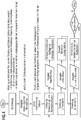
- FIG. 4 If one then implements these measuring principles or models as a method according to the invention, an embodiment according to FIG. 4 be used.
- FIG. 4 schematically shows a flowchart of the embodiment and begins in a first step S1 at an initial state "Start" from which in a second step S2, a calibration is performed, which determines in a third step S3 as a result, a voltage and angular offset in which a measurement takes place at a defined position of the transmitter and the detector, for example, that they are directly above one another, wherein a receiving voltage at each receiver and angle between the individual receiving coils is determined.
- a coarse positioning ensues, which follows a subsequent estimation of the angle of rotation, for example according to one of the approaches described above or a combination thereof, in a fifth step S5.
- step S6 This is followed in a sixth step S6 by the output of the solid angle Yaw / pitch / roll, which follows a rotation of the detector to zero position (at arbitrary translation) in a seventh step S7.
- a model for example the one explained above, is selected, with which the xy-translation can be estimated in an eleventh step S11 and a displacement of the detector / transmitter to zero position can be carried out in a twelfth step S12.
Landscapes
- Health & Medical Sciences (AREA)
- Life Sciences & Earth Sciences (AREA)
- Engineering & Computer Science (AREA)
- Medical Informatics (AREA)
- Physics & Mathematics (AREA)
- General Health & Medical Sciences (AREA)
- Pathology (AREA)
- Molecular Biology (AREA)
- High Energy & Nuclear Physics (AREA)
- Nuclear Medicine, Radiotherapy & Molecular Imaging (AREA)
- Radiology & Medical Imaging (AREA)
- Surgery (AREA)
- Heart & Thoracic Surgery (AREA)
- Biomedical Technology (AREA)
- Optics & Photonics (AREA)
- Animal Behavior & Ethology (AREA)
- Biophysics (AREA)
- Public Health (AREA)
- Veterinary Medicine (AREA)
- General Physics & Mathematics (AREA)
- Biochemistry (AREA)
- Chemical & Material Sciences (AREA)
- Analytical Chemistry (AREA)
- Immunology (AREA)
- Theoretical Computer Science (AREA)
- Pulmonology (AREA)
- Computer Vision & Pattern Recognition (AREA)
- Spectroscopy & Molecular Physics (AREA)
- Measurement Of Length, Angles, Or The Like Using Electric Or Magnetic Means (AREA)
- Geophysics And Detection Of Objects (AREA)
- Measuring Magnetic Variables (AREA)
Abstract
Die Erfindung betrifft ein Verfahren zum Betreiben eines aus einem Röntgenstrahler und Röntgendetektor bestehenden Röntgengerätes, bei welchem am Röntgenstrahler ein magnetisches Wechselfeld erzeugt und ausgesandt wird, am Röntgendetektor durch mindestens zwei zur Erfassung von jeweils zumindest einer mit dem magnetischen Wechselfeld korrelierenden physikalischen Größe, insbesondere der Magnetfeldstärke, angebrachten Sensoren eine Messung der physikalischen Größen durchgeführt wird, auf Grundlage der Messung eine Ausrichtung des Röntgendetektors relativ zum Röntgenstrahler bestimmt wird. Ferner betrifft die Erfindung ein Röntgengerät zur Durchführung des Verfahrens.The invention relates to a method for operating an X-ray source and X-ray detector X-ray apparatus in which the X-ray generator generates and emits an alternating magnetic field at the X-ray detector by at least two for detecting each of at least one correlated with the magnetic alternating field physical quantity, in particular the magnetic field strength , attached sensors, a measurement of the physical quantities is performed, based on the measurement, an orientation of the X-ray detector is determined relative to the X-ray source. Furthermore, the invention relates to an X-ray machine for carrying out the method.
Description
Die vorliegende Erfindung betrifft ein Verfahren zum Betreiben eines Röntgengerätes gemäß dem Oberbegriff des Patentanspruchs 1 sowie ein Röntgengerät gemäß dem Oberbegriff des Anspruchs 10.The present invention relates to a method for operating an X-ray apparatus according to the preamble of
Es ist bekannt, dass eine Kenntnis der relativen Lage und Position zwischen Strahler und Detektor eines Röntgengerätes notwendig ist, um ein definiertes Röntgenbild mit dem Röntgengerät, d.h. mit der Anordnung bestehend aus einem Röntgenstrahler und einem Röntgendetektor, zu erhalten.It is known that knowledge of the relative position and position between the radiator and the detector of an X-ray apparatus is necessary in order to obtain a defined X-ray image with the X-ray apparatus, i. with the arrangement consisting of an X-ray source and an X-ray detector to obtain.
Lage im Sinne des vorliegenden Dokumentes umfasst eine translatorische Verschiebung des Detektors relativ zum Strahler ebenso wie eine Verkippung/Verdrehung des Detektors relativ zum Strahler, jeweils in allen 3 Raumachsen, welche im Dokument im deutschen Sprachraum mit Roll-Nick-Gier-Winkel und im englischen Sprachraum, sowie dem vorliegenden Dokument mit roll-pitch-yaw Winkel bezeichnet werden können, die eine in der Fachwelt bekannte Möglichkeit zur Beschreibung der Orientierung eines Objekts im dreidimensionalen Raum darstellen.Position within the meaning of the present document comprises a translatory displacement of the detector relative to the radiator as well as a tilt / rotation of the detector relative to the radiator, each in all 3 spatial axes, which in the document in the German-speaking area with roll pitch yaw angle and in English Language space, as well as the present document with roll-pitch-yaw angle can be designated, which represent a well-known in the art way to describe the orientation of an object in three-dimensional space.
Die Information bzgl. der relativen Lage und Position eines Röntgendetektors zum dazugehörigen Röntgenstrahler steht bei heutigen Geräten nicht zur Verfügung.The information regarding the relative position and position of an X-ray detector to the associated X-ray source is not available in today's devices.
Es ist Aufgabe der vorliegenden Erfindung, eine Lösung anzugeben, die eine verlässliche Bestimmung der Lage ermöglicht.It is an object of the present invention to provide a solution that allows a reliable determination of the situation.
Diese Aufgabe wird durch ein Verfahren zum Betreiben eines Röntgengerätes gemäß den Merkmalen des Patentanspruchs 1 sowie durch das Röntgengerät gemäß den Merkmalen des Anspruchs 10 gelöst. Weitere vorteilhafte Weiterbildungen sind durch die Unteransprüche gegeben.This object is achieved by a method for operating an X-ray apparatus according to the features of
Beim erfindungsgemäßen Verfahren zum Betreiben eines aus einem Röntgenstrahler und Röntgendetektor bestehenden Röntgengerätes wird
- a) am Röntgenstrahler ein magnetisches Wechselfeld erzeugt und ausgesandt,
- b) am Röntgendetektor durch mindestens zwei zur Erfassung von jeweils zumindest einer mit dem magnetischen Wechselfeld korrelierenden physikalischen Größe, insbesondere der Magnetfeldstärke, angebrachten Sensoren eine Messung der physikalischen Größen durchgeführt,
- c) auf Grundlage der Messung eine Ausrichtung des Röntgendetektors relativ zum Röntgenstrahler bestimmt.
- a) generates and emits an alternating magnetic field at the X-ray emitter,
- b) carrying out a measurement of the physical quantities on the X-ray detector by means of at least two sensors for detecting in each case at least one physical variable correlated with the alternating magnetic field, in particular the magnetic field strength,
- c) determines an orientation of the X-ray detector relative to the X-ray source based on the measurement.
Die Erfindung hat den Vorteil, die bislang manuell durchgeführte Ausrichtung, die im Sinne der Erfindung durch die Lage des Detektors im Bezug zum Strahler definiert ist, zu automatisieren, bei der der Abstand zwischen Röntgenstrahler und -detektor zum Teil mit einem Maßband ausgemessen wurde. Demgegenüber ermöglicht die Erfindung auch präzisere Lagebestimmungen. Vor allem weil eine Verkippung des Detektors nicht messtechnisch ermittelt, sondern nur per "Augenmaß" korrigiert werden konnte. Die Erfindung vermeidet dabei Fehler bei der Röntgenaufnahme, die dazu führten, dass beispielsweise das Röntgenbild entweder von schlechter Qualität war (Field of View, Unschärfe, Kontrastarmut) oder wiederholt werden musste, was eine zusätzliche Strahlenbelastung bedeutete.The invention has the advantage of automating the previously manually performed alignment, which is defined in the context of the invention by the position of the detector with respect to the radiator, in which the distance between the X-ray source and detector was measured in part with a tape measure. In contrast, the invention also allows more precise position determinations. Especially because a tilt of the detector was not measured by measurement, but could only be corrected by "good judgment". The invention avoids errors in the X-ray recording, which meant that, for example, the X-ray image was either of poor quality (field of view, blur, low contrast) or had to be repeated, which meant an additional radiation exposure.
Bei einer vorteilhaften Weiterbildung der Erfindung erfolgt zur Bestimmung die Berechnung einer Translation und/oder Rotation in zumindest je einer Ebene.In an advantageous development of the invention, the calculation of a translation and / or rotation in at least one plane takes place for the determination.
Hierdurch können je nach Anzahl der Ebenen und Art des ermittelten Lageversatzes, translatorisch und/oder rotatorisch, diverse mathematische Algorithmen zur akkuraten Schätzung der Lage gezielt ausgewählt bzw. eingesetzt werden.As a result, depending on the number of levels and the type of positional offset determined, translational and / or rotational, various mathematical algorithms can be selectively selected or used for the accurate estimation of the position.
Werden mindestens zwei Sendemittel zur Aussendung des magnetischen Wechselfeldes zueinander symmetrisch und/oder die mindestens zwei Sensoren zueinander symmetrisch angeordnet betrieben, wobei die Messung derart durchgeführt wird, dass ein Verhältnis der seitens der Sensoren empfangenen physikalischen Größe, insbesondere Empfangsfeldstärke, zueinander gebildet wird und wobei die Bestimmung auf Grundlage des Verhältnisses erfolgt, kann eine einfache Ermittlung/Schätzung der Translation (Translationsversatz) implementiert werden. Die jedoch nur anwendbar ist, soweit keine (Ver-)Kippungs-/Verdrehungsmöglichkeit des Detektors möglich ist. Hiermit wird im Sinne der Erfindung ein reines Gradientenverfahren bereitgestellt.If at least two transmitting means for transmitting the alternating magnetic field are operated symmetrically to one another and / or the symmetrically arranged symmetrically to each other, the measurement is carried out such that a ratio of the physical size received by the sensors, in particular receiving field strength, is formed to each other and wherein the Determination based on the ratio, a simple determination / estimation of the translation (translation offset) can be implemented. However, this is only applicable if no (ver) tilting / twisting possibility of the detector is possible. For the purposes of the invention, this provides a pure gradient method.
Um auch bei Verkippung/Verdrehung eine Bestimmung möglich zu machen, kann das Verfahren derart weitergebildet werden, dass mindestens vier Sensoren auf dem Röntgendetektor angeordnet betrieben werden, die Korrelation derart durchgeführt wird, dass durch in Bezug setzen von den zum aktuellen Zeitpunkt empfangenen physikalischen Größen zu einer Referenzgröße eine Positionsschätzung ermittelt wird und die Bestimmung auf Grundlage der Positionsschätzung erfolgt. Hiermit kommt ein im Sinne der Erfindung als Kugelmodell zu bezeichneter Bestimmungsansatz zum Einsatz.In order to make a determination possible even when tilting / twisting, the method can be developed in such a way that at least four sensors are operated on the X-ray detector, the correlation is carried out in such a way that by taking into account the physical quantities received at the current time a reference estimate, a position estimate is determined and the determination is made based on the position estimate. Hereby comes in the sense of the invention as a spherical model designated determination approach used.
Alternativ, insbesondere falls kein Translationsversatz möglich ist, oder ergänzend, kann das Verfahren gemäß Erfindung derart weitergebildet werden, dass mindestens ein Paar von Sensoren auf dem Röntgendetektor orthogonal zueinander angeordnet betrieben werden, dass die Messung derart durchgeführt wird, dass durch Anwendung trigonometrischer Funktionen, insbesondere des Arkustangens, der Einfallswinkel auf Grundlage der empfangenen physikalischen Größen zwischen den beiden Sensoren ermittelt wird und die Bestimmung auf Grundlage des Einfallswinkels erfolgt. Hierdurch wird eine Rotationsermittlung, d.h. genauer die Bestimmung eines Versatzes der Rotation bzgl. Strahler gewährleistet, die auf Grundlage einer trigonometrischen Funktion, insbesondere dem Arkustangens, erfolgen kann.Alternatively, in particular if no translation offset is possible, or in addition, the method according to the invention can be developed in such a way that at least one pair of sensors on the X-ray detector are operated orthogonally to one another, that the measurement is carried out such that by using trigonometric functions, in particular of the arctangent, the angle of incidence is determined based on the received physical quantities between the two sensors and the determination is made based on the angle of incidence. In this way, a rotation determination, ie more precisely the determination of an offset of the rotation with respect to. Radiator ensures, based on a trigonometric Function, in particular the Arctangent can be done.
Die Genauigkeit der Versatzermittlung der Rotation kann weiter gesteigert werden, wenn die Erfindung derart weitergebildet wird, dass bei einem Einsatz von mehr als einem Paar Sensoren je Paar ein Einfallswinkel bestimmt wird, ein Mittelwert aus dem Einfallswinkel der Paare gebildet wird und die Bestimmung auf Grundlage des Mittelwerts des Einfallswinkels erfolgt.The accuracy of offset determination of the rotation can be further increased if the invention is developed such that when using more than one pair of sensors per pair an angle of incidence is determined, an average of the angle of incidence of the pairs is formed and the determination based on the Average value of the angle of incidence takes place.
Bevorzugt wird dabei das Wechselfeld derart erzeugt, dass das Magnetfeld eine Frequenz in einem Bereich zwischen 75 KHz und 150 KHz, insbesondere 125Khz, aufweist. Hierdurch ist ein Frequenzbereich implementiert, der besonders gut geeignet ist, die Materialien und den menschlichen Körper nahezu ohne störende Einflüsse zu durchdringen. Insbesondere 125 KHz sind dabei regulatorisch vorgegeben.In this case, the alternating field is preferably generated such that the magnetic field has a frequency in a range between 75 kHz and 150 kHz, in particular 125 kHz. As a result, a frequency range is implemented, which is particularly well suited to penetrate the materials and the human body with almost no disturbing influences. In particular, 125 kHz are prescribed by regulatory means.
Werden als Sendemittel ein-, zwei- und oder dreidimensionale Spulen betrieben, desto akkurater wird die Bestimmung.If one-, two- and / or three-dimensional coils are used as transmitting means, the determination becomes more accurate.
Wird die Erfindung derart weitergebildet, dass als Sensoren Empfangsspulen, 3-Achsen-Beschleunigungssensoren und/oder 3-Achsen-Drehratensensoren betrieben werden, erhält man für die Implementierung diverse Freiheitsgrade, da jede der genannten Sensorarten Eigenschaften mit sich bringt, die für den konkreten Einsatz besonders von Vorteil sein können.If the invention is developed in such a way that receiver coils, 3-axis acceleration sensors and / or 3-axis rotation rate sensors are operated as sensors, various degrees of freedom are obtained for the implementation since each of the sensor types mentioned has characteristics which are suitable for concrete use especially beneficial.
Das erfindungsgemäße Röntgengerät, bestehend aus einem Röntgenstrahler und Röntgendetektor, weist einen Röntgenstrahler auf, der ausgestaltet ist mit Sendern zum Erzeugen und Senden eines magnetischen Wechselfelds sowie einen Röntgendetektor, der ausgestaltet ist mit mindestens zwei zur Erfassung von jeweils zumindest einer mit dem magnetischen Wechselfeld korrelierenden physikalischen Größe, insbesondere der Magnetfeldstärke, Sensoren und erste Mittel zur Durchführung einer Korrelation der physikalischen Größen. Er weist auch zweite Mittel auf, die derart ausgestaltet sind, dass auf Grundlage der Messung eine Ausrichtung des Röntgendetektors relativ zum Röntgenstrahler bestimmt wird.The X-ray device according to the invention, comprising an X-ray emitter and X-ray detector, has an X-ray emitter which is designed with transmitters for generating and transmitting an alternating magnetic field and an X-ray detector which is designed with at least two for detecting in each case at least one physical correlation with the magnetic alternating field Size, in particular the magnetic field strength, sensors and first means for performing a correlation of the physical quantities. He also has second Means, which are designed such that, based on the measurement, an orientation of the X-ray detector is determined relative to the X-ray source.
Das Röntgengerät stellt eine Implementierung dar, die das Verfahren und damit auch dessen Vorteile verwirklicht.The X-ray machine represents an implementation that realizes the method and thus also its advantages.
Das Gleiche gilt für die Weiterbildungen des Röntgengeräts, die Mittel zur Durchführung des Verfahrens und seiner Weiterbildungen aufweisen.The same applies to the developments of the x-ray device, which have means for carrying out the method and its developments.
Die vorliegende Erfindung wird nun anhand von in den Figuren dargestellten Ausführungsbeispielen der Erfindung näher erläutert. Dabei zeigt
- FIG 1
- eine den folgenden Ausführungsbeispielen als Ausgangsituation zugrundeliegende Röntgengerätanordnung gemäß Stand der Technik,
- FIG 2
- schematisch ein erstes Ausführungsbeispiel, welches die erfindungsgemäße Anwendung eines durch die Erfindung definiertes und bezeichnetes Kugelmodell als Messprinzip aufzeigt,
- FIG 3
- schematisch ein zweites Ausführungsbeispiel, welches die erfindungsgemäße Anwendung eines durch die Erfindung definiertes und bezeichnetes Gradientenmodell als Messprinzip aufzeigt,
- FIG 4
- ein Ablaufdiagram eines möglichen Ausführungsbeispiels des erfindungsgemäßen Verfahrens.
- FIG. 1
- an X-ray apparatus arrangement according to the prior art, which is the starting point for the following exemplary embodiments,
- FIG. 2
- schematically a first embodiment, which shows the inventive application of a defined and defined by the invention spherical model as a measuring principle,
- FIG. 3
- schematically a second embodiment, which shows the inventive application of a defined and defined by the invention gradient model as a measuring principle,
- FIG. 4
- a flow chart of a possible embodiment of the method according to the invention.
Die nachfolgend näher geschilderten teilweise nicht dargestellten Ausführungsbeispiele bzw. Ausgestaltungen einzelner Elemente hiervon stellen bevorzugte Ausführungsformen der vorliegenden Erfindung dar. Diese ist jedoch nicht darauf beschränkt.The exemplary embodiments or configurations of individual elements thereof, which are not described in detail below, represent preferred embodiments of the present invention. However, this is not limited thereto.
Zu erkennen ist der prinzipielle Aufbau einer Röntgengeräteanordnung, die aus einem (Röntgen-)Strahler und einem (Röntgen-)Detektor besteht, zwischen denen die zu untersuchende Person platziert wird.Evident is the basic structure of an X-ray device arrangement, which consists of an (X-ray) emitter and an (X-ray) detector, between which the person to be examined is placed.
Des Weiteren ist dargestellt, in welcher Weise die Lage des Röntgendetektors sich verändern kann, so dass er zum in der Regel unbeweglichen Strahler einen Versatz aufweist.Furthermore, it is shown in which way the position of the X-ray detector can change, so that it has an offset to the generally immobile radiator.
Zu erkennen ist, dass eine Verschiebung des Detektors in der x-y-Ebene erfolgen kann. Also ein translatorischer Versatz. Zudem kann der Detektor auch gelegentlich so ausgeführt sein, dass er um eine der drei Achsen im Raum x-y-z gedreht ist.It can be seen that a displacement of the detector can take place in the x-y plane. So a translatory offset. In addition, the detector may occasionally be designed to be rotated about one of the three axes in space x-y-z.
Die Bestimmung der sich so ergebenden Lage des Detektors wird in der Regel manuell durchgeführt und führt zu den eingangs beschriebenen Nachteilen.The determination of the resulting position of the detector is usually carried out manually and leads to the disadvantages described above.
Diese werden erfindungsgemäß dadurch behoben, dass eine automatische Erfassung des Versatzes bereitgestellt wird.These are inventively remedied that an automatic detection of the offset is provided.
Das in
Hiervon ausgehend lassen sich für die denkbaren Versatzmöglichkeiten, der Drehwinkel und die Position ermitteln.On this basis, it is possible to determine the conceivable offset possibilities, the angle of rotation and the position.
Für die Ermittlung des Drehwinkels gelten u.a., wenn gemäß dem Ausführungsbeispiels die Sender ein Wechselmagnetfeld erzeugen und die Empfänger als Spulen ausgestaltet sind, folgende Grundsätze:
- Die Empfangsspannungen werden von mind. zwei orthogonalen Empfangsspulen ermittelt,
- mit Hilfe der trigonometrischen Funktion Arkustangens kann bei Annahme von linear ausgesendeten Magnetfeldern der Einfallswinkel zwischen den beiden Empfangsspulen bestimmt werden,
- bei mehreren Empfangsspulenpaaren wird der Mittelwert des geschätzten Drehwinkels bestimmt,
- bei Einsatz von drei Empfangsspulen lässt sich die Lage allgemein durch trigonometrische Funktionen bestimmen, ist also nicht auf Arkustangens beschränkt,
- die Genauigkeit der Schätzung ist abhängig von:
- o Homogener Feldverteilung erzeugt durch Sendespulen
- o Orthogonalität der Empfangsspulen (Kopplung, Einbau)
- o Signal-zu-Rausch-Abstand.
- The reception voltages are determined by at least two orthogonal receiver coils.
- with the help of the trigonometric function arctangent, the angle of incidence between the two receiver coils can be determined assuming linearly emitted magnetic fields
- if several pairs of receive coils are used, the mean value of the estimated rotation angle is determined,
- if three receiver coils are used, the position can generally be determined by trigonometric functions, ie it is not restricted to arctangent lines,
- the accuracy of the estimate depends on:
- o Homogeneous field distribution generated by transmitting coils
- o Orthogonality of the receiver coils (coupling, installation)
- o Signal-to-noise ratio.
Ferner gilt grundsätzlich für die erfindungsgemäße Ausführung von Drehwinkeln gemäß Beispiel:
- Eine Verkippung bzw. Drehung im Raum (yaw, pitch, roll) ausschließlich um eine Achse kann über zwei um 90°gekreuzte Empfangsspulen (Rx1, Rx2) gemessen werden,
- Einbauort sind die Hauptachsen des Detektors
- ∘ yaw Empfangsspulen liegen in der x'y'-Ebene,
- ∘ pitch Empfangsspulen liegen in der x'z'-Ebene,
- ∘ roll Empfangsspulen liegen in der y'z'-Ebene,
- geschätzter Winkel = atan(Messung an Rx1/Messung an Rx2)
- um eine Verkippung um zwei Achsen zu erfassen ist als eine Weiterbildung eine 3D-Empfangsspule notwendig,
- Kalibration der Empfangsspulen erfolgt vor einer Winkelschätzung,
- zu beachten ist, dass eine Winkelmessung mittels trigonometrischer Funktion nur bei einer homogenen Phase im Raum anwendbar ist.
- A tilting or rotation in the space (yaw, pitch, roll) exclusively about an axis can be measured via two receiver coils (R x1 , R x2 ) crossed by 90 °,
- Installation location are the main axes of the detector
- ∘ yaw receive coils lie in the x'y'-plane,
- Empfang pitch receive coils lie in the x'z'-plane,
- Empfang roll receive coils lie in the y'z 'plane,
- estimated angle = atan (measurement at R x1 / measurement at R x2 )
- in order to detect tilting about two axes, a further development of a 3D receiver coil is necessary.
- Calibration of the receiver coils takes place before an angle estimation,
- It should be noted that an angle measurement using a trigonometric function is only applicable to a homogeneous phase in space.
Für die Ermittlung der Position des Detektors bei der gegebenen Ausgangssituation sollen zwei Ausführungsbeispiele im Wesentlichen gekennzeichnet durch den Einsatz von Messprinzipien zum Einsatz kommen, eines, das als Kugelmodell bezeichnet werden kann und eines, welches als Gradientenmodell/- verfahren bezeichnet werden kann, wobei das Kugelmodell gemäß Ausführungsbeispiel sich dadurch auszeichnet, dass
- die Position des Detektors relativ zum Sender mittels eines Kugelmodells geschätzt wird,
- die
gezeigten 4 Empfänger zur Schätzung der Position x,y,z des Detektors zum Einsatz kommen, - das Kugelmodell dabei auf einem empirischen Modell basiert, wobei
- das empirische Modell auf Messungen der Feldstärke, die einmalig bei relevanten Abständen zwischen Sender und Detektor und in einem relevanten Bereich bei konstantem Abstand ermittelt werden, basiert, und wobei
- für jeden gemessenen Wert eine Kostenfunktion für jeden Empfänger minimiert wird.
- the position of the detector relative to the transmitter is estimated by means of a spherical model,
- the 4 receivers shown are used to estimate the position x, y, z of the detector,
- the spherical model is based on an empirical model, whereby
- the empirical model based on measurements of the field strength, which are determined once at relevant distances between transmitter and detector and in a relevant range at a constant distance, and wherein
- for each measured value, a cost function is minimized for each recipient.
Beim Kugelmodell kommen dabei folgende mathematische, die Gegebenheiten der Röntgenanordnung beschreibende/modellierende, Gleichungen zum Einsatz: ![]()
![]()
![]()
![]()
![]()
![]()
![]()
![]()
Hiermit sind die Modellgleichungen für die 4 Empfänger gegeben. Dabei ist für einen Empfänger mit Offset zum Mittelpunkt des Detektors und mit xn, yn, zn, abhängig von den Raumwinkeln yaw α, roll β, und pitch γ grundsätzlich die Eulermatrix M mit 

Die Position, d.h. die Verschiebung gemäß Darstellung um x=y= 10 cm, des Detektors zum Mittelpunkt bezüglich aller Sender Txn wird dabei aus den Empfangsspannungen aller Empfänger Rxn geschätzt.The position, ie the displacement as shown by x = y = 10 cm, of the detector with respect to the center with respect to all transmitters T xn is estimated from the reception voltages of all receivers R xn .
Dabei gilt für die Schätzung der x-y Translation mittels Kugelgleichung, dass
- die xy-Schätzung auf einem Polynom basiert, wobei für das Polynom gilt, dass
- o die Feldverteilung nicht symmetrisch ist,
- o ein Polynom den Mittelwert aller Kurven bestimmt,
- o mit Hilfe des Polynoms jeder gemessenen Empfangsspannung ein Radius zugeordnet wird,
- für die Schätzung genügen erfindungsgemäß also mindestens drei Empfangsspulen (ausreichend da bzw. wenn der z-Abstand konstant und bekannt ist),
- ein Schätzfehler sich mit Hinzunahme weiterer Empfänger minimiert,
- es geeignet ist für Verschiebungen geringeren Ausmaßes, da mit größer werdenden Verschiebungen Messfehler zunehmen, soweit Polynome zur Schätzung verwendet werden,
- Schätzprinzip auch bei einer Verdrehung des Detektors anwendbar ist,
- der mittlere euklidische Abstand 1,7 cm beträgt.
- the xy estimate is based on a polynomial, where the polynomial holds that
- o the field distribution is not symmetrical,
- o a polynomial determines the mean of all curves,
- o a radius is assigned to each measured received voltage with the help of the polynomial,
- according to the invention, therefore, at least three receiver coils suffice (sufficiently there or if the z-spacing is constant and known),
- an estimation error is minimized with the addition of additional receivers,
- it is suitable for shifts of lesser extent, since with increasing shifts measurement errors increase, as far as polynomials are used for the estimation,
- Estimation principle is also applicable to a rotation of the detector,
- the mean Euclidean distance is 1.7 cm.
Die durch eindimensionale Empfängerspulen erreichte Genauigkeit ist ausreichend und bietet eine günstige Lösung. Genauere Ergebnisse lassen sich auch durch den Einsatz von zweidimensionalen oder dreidimensionalen Spulen erzielen.The accuracy achieved by one-dimensional receiver coils is sufficient and offers a favorable solution. More accurate results can also be achieved through the use of two-dimensional or three-dimensional coils.
Wohingegen das Gradientenverfahren gemäß Ausführungsbeispiel, das auf Grundlage einer Ausgangsituation wie in
- die xy-Verschiebung mittels Gradient bestimmt wird,
- die Verschiebung über ein Empfangsverhältnis einer symmetrischen Sende- und Empfangskonstellation bestimmt werden kann, wobei
- dies nur anwendbar ist, wenn keine Drehung/Verkippung vorliegt,
- der Gradient nur für einen Abstand gültig ist, so dass das Prinzip eingesetzt wird, dass im Fall, dass bei zwei sich gegenüberliegenden Empfängern nicht die gleiche Empfangsfeldstärke aufgewiesen wird, eine Verschiebung vorliegt,
- der mittlere euklidische Abstand mit 0,3 cm gegeben ist.
- the xy shift is determined by gradient,
- the shift can be determined via a reception ratio of a symmetrical transmission and reception constellation, wherein
- this is only applicable if there is no rotation / tilt,
- the gradient is only valid for a distance, so that the principle is used that in the event that the same reception field strength is not exhibited for two mutually opposite receivers, there is a shift,
- the average Euclidean distance is given as 0.3 cm.
Es gilt ferner, dass ein geeignetes Polynom für die Schätzung gemäß Ausführungsbeispiel der Erfindung unter Beachtung folgender Punkte bestimmt werden kann:
- Die gemessenen Empfangsspannungen hängen von der Position der Empfangsspulen auf dem Detektor ab (Rx1 und Rx2 haben zur Detektormitte einen größeren Abstand als Rx3 und Rx4).
- Für eine Grobschätzung des Abstandes genügt die Bestimmung eines Polynoms, welches auf der Addition der Spannungen aller Empfangsspulen basiert.
- Für eine genaue Abstandsschätzung ist ein Polynom zu bestimmen, dass sich aus den Spannungen von Empfangsspulen ergibt, die einen identischen Abstand zur Mitte des Detektors aufweisen.
- The measured reception voltages depend on the position of the receiver coils on the detector (R x1 and R x2 are spaced apart from the center of the detector by R x3 and R x4 ).
- For a rough estimation of the distance, it is sufficient to determine a polynomial which is based on the addition of the voltages of all receiver coils.
- For a precise distance estimate, a polynomial is to be determined which results from the voltages of receiver coils which are at an identical distance from the center of the detector.
Hierdurch kann, sofern jeder Empfangsspule abhängig von ihrer Position auf der Detektorplatte das entsprechende Polynom zugeordnet wird, eine gute Korrelation von Radien zu Empfangsspannungen bei verschiedenen Abständen gewährleistet werden.In this way, if each receiving coil is assigned the corresponding polynomial depending on its position on the detector plate, a good correlation of radii to receiving voltages at different distances can be ensured.
Da gemäß einer alternativen bzw. ergänzenden Weiterbildung mittels Polynom auch für jeden Empfänger eine Kugelgleichung aufgestellt werden kann, kann auch eine Schätzung mittels Kugelmodell erfolgen, wobei die z-Komponente sehr gut geschätzt werden kann, wenn die geschätzte x- und y-Komponente idealerweise immer 0 entsprechen.Since according to an alternative or additional development by means of polynomial for each receiver a ball equation can be established, an estimate can be made by means of spherical model, the z-component can be very well estimated if the estimated x and y component ideally always 0 correspond.
Implementiert man nun diese Messprinzipien bzw. Modelle als erfindungsgemäßes Verfahren, kann ein Ausführungsbeispiel gemäß
Die
In einem vierten Schritt S4 erfolgt dann eine grobe Positionierung, die eine anschließende Schätzung des Drehwinkels, beispielsweise gemäß einer der oben beschriebenen Ansätze oder einer Kombination hiervon, in einem fünften Schritt S5 nachfolgt.In a fourth step S4, a coarse positioning ensues, which follows a subsequent estimation of the angle of rotation, for example according to one of the approaches described above or a combination thereof, in a fifth step S5.
Hierauf folgt in einem sechsten Schritt S6 die Ausgabe der Raumwinkel Yaw/Pitch/Roll, der eine Drehung des Detektors auf Nulllage (bei beliebiger Translation) in einem siebten Schritt S7 folgt.This is followed in a sixth step S6 by the output of the solid angle Yaw / pitch / roll, which follows a rotation of the detector to zero position (at arbitrary translation) in a seventh step S7.
Dies führt zur Schätzung der z-Translation in einem achten Schritt S8 und Ausgabe der z-Koordinate in einem neunten Schritt S9. Im Anschluss wird dann in einem zehnten Schritt S10 ein Modell, beispielsweise der oben erläuterten, ausgewählt, mit dem in einem elften Schritt S11 die xy-Translation geschätzt und in einem zwölften Schritt S12 eine Verschiebung des Detektors/Senders auf Nullposition durchgeführt werden kann.This leads to the estimation of the z-translation in an eighth step S8 and output of the z-coordinate in a ninth step S9. Subsequently, in a tenth step S10, a model, for example the one explained above, is selected, with which the xy-translation can be estimated in an eleventh step S11 and a displacement of the detector / transmitter to zero position can be carried out in a twelfth step S12.
Durch eine Auswertung in einem dreizehnten Schritt S13, ob n-Iterationen erreicht worden sind, wird im positiven Fall das Verfahren beendet und geht in einem vierzehnten Schritt S14 in den Zustand "Stop" über.By evaluating in a thirteenth step S13 whether n iterations have been reached, the method is terminated in the affirmative case and changes to the state "Stop" in a fourteenth step S14.
Falls nicht, werden die Schritte fünf bis elf S5...S11 wiederholt.If not, steps five to eleven S5 ... S11 are repeated.
Der in diesem Dokument beschriebene Ansatz ist nicht auf die in den Figuren erläuterten Beispiele beschränkt, sondern umfasst alle durch die Ansprüche umfassten Lösungen, die ausschließlich auf Amplitudenmessungen und deren Auswertung basieren und bei denen die Lage im Raum von Objekten und dessen Position mit Hilfe des Einsatzes von einer hinsichtlich des Typs homogenen Auswahl von Sensoren aus einer grundsätzlich möglichen Auswahl aus mehreren Sensortypen (Beschleunigungsensor, Gyro,) bewerkstelligt werden, die der fachfremden Lageregelung von Flugobjekten vergleichbar eingesetzt werden. Vergleichbar, da deren Anwendung im medizinischen Umfeld und im Innenbereich von Gebäuden nicht vorgesehen und daher zum Teil nur mit Anpassungen/Einschränkungen möglich ist.The approach described in this document is not limited to the examples illustrated in the figures, but encompasses all solutions encompassed by the claims which are based exclusively on amplitude measurements and their evaluation and in which the position in the space of objects and their position with the help of the insert are made of a type of homogeneous selection of sensors from a fundamentally possible selection of several types of sensors (acceleration sensor, gyro,), which are used the non-specialized attitude control of flying objects comparable. Comparable, since their use in the medical environment and indoors of buildings not provided and therefore partly only with adjustments / restrictions is possible.
Claims (11)
Applications Claiming Priority (1)
| Application Number | Priority Date | Filing Date | Title |
|---|---|---|---|
| DE102016207021.5A DE102016207021A1 (en) | 2016-04-26 | 2016-04-26 | Method for operating an X-ray device and X-ray device |
Publications (3)
| Publication Number | Publication Date |
|---|---|
| EP3239700A1 true EP3239700A1 (en) | 2017-11-01 |
| EP3239700B1 EP3239700B1 (en) | 2023-09-27 |
| EP3239700C0 EP3239700C0 (en) | 2023-09-27 |
Family
ID=58669601
Family Applications (1)
| Application Number | Title | Priority Date | Filing Date |
|---|---|---|---|
| EP17167096.1A Active EP3239700B1 (en) | 2016-04-26 | 2017-04-19 | Method for operating an x-ray device and x-ray device |
Country Status (4)
| Country | Link |
|---|---|
| US (1) | US10578459B2 (en) |
| EP (1) | EP3239700B1 (en) |
| CN (1) | CN107307874B (en) |
| DE (1) | DE102016207021A1 (en) |
Cited By (1)
| Publication number | Priority date | Publication date | Assignee | Title |
|---|---|---|---|---|
| EP4166086A4 (en) * | 2020-06-16 | 2023-12-06 | CareRay Digital Medical Technology Co., Ltd. | Real-time spatial precise magnetic positioning apparatus, ray imaging system, and real-time spatial precise magnetic positioning method |
Families Citing this family (1)
| Publication number | Priority date | Publication date | Assignee | Title |
|---|---|---|---|---|
| CN108078577B (en) * | 2017-11-22 | 2020-10-16 | 上海奕瑞光电子科技股份有限公司 | Digital X-ray radiation system, attitude detection method and attitude detection system |
Citations (3)
| Publication number | Priority date | Publication date | Assignee | Title |
|---|---|---|---|---|
| US5463669A (en) * | 1994-09-08 | 1995-10-31 | Kaplan; Jerome I. | Dental X-ray alignment system |
| DE102010020782A1 (en) * | 2010-05-18 | 2011-11-24 | Siemens Aktiengesellschaft | X-ray device e.g. C-arm rotation angiography device, for e.g. three-dimensional imaging of patient, has determination units connected with X-ray source and detector to determine movement and/or position of source and detector, respectively |
| WO2012127117A1 (en) * | 2011-03-21 | 2012-09-27 | Planmeca Oy | Arrangement for intra-oral x-ray imaging |
Family Cites Families (9)
| Publication number | Priority date | Publication date | Assignee | Title |
|---|---|---|---|---|
| JP4286127B2 (en) * | 2003-12-25 | 2009-06-24 | オリンパス株式会社 | In-subject position detection system |
| US7236567B2 (en) * | 2005-03-24 | 2007-06-26 | Siemens Aktiengesellschaft | Method and apparatus for synchronizing operation of an x-ray system and a magnetic system |
| US20070001905A1 (en) * | 2005-06-30 | 2007-01-04 | Esa Eronen | Detecting the position of X-ray detector |
| DE102010020350B4 (en) * | 2010-05-12 | 2017-02-23 | Siemens Healthcare Gmbh | Method for positioning the focus of a gradient field and treatment device |
| US8821015B2 (en) * | 2011-03-08 | 2014-09-02 | Carestream Health, Inc. | Alignment apparatus for X-ray imaging system |
| US9631950B2 (en) * | 2011-08-05 | 2017-04-25 | Evatran Group, Inc. | Method and apparatus for aligning a vehicle with an inductive charging system |
| KR102121721B1 (en) | 2013-03-04 | 2020-06-26 | 삼성전자주식회사 | Mobile x-ray imaging apparatus and control method for the same |
| CN106443535B (en) * | 2013-05-21 | 2019-04-23 | 上海联影医疗科技有限公司 | The system of imaging magnetic field measurement and correction in magnetic resonance device |
| KR101618213B1 (en) * | 2013-06-21 | 2016-05-04 | 삼성전자주식회사 | Information providing method and apparatus for aligning x-ray tube and detector of mobile x-ray, and wireless detector |
-
2016
- 2016-04-26 DE DE102016207021.5A patent/DE102016207021A1/en active Pending
-
2017
- 2017-04-19 EP EP17167096.1A patent/EP3239700B1/en active Active
- 2017-04-25 US US15/496,593 patent/US10578459B2/en active Active
- 2017-04-26 CN CN201710281921.3A patent/CN107307874B/en active Active
Patent Citations (3)
| Publication number | Priority date | Publication date | Assignee | Title |
|---|---|---|---|---|
| US5463669A (en) * | 1994-09-08 | 1995-10-31 | Kaplan; Jerome I. | Dental X-ray alignment system |
| DE102010020782A1 (en) * | 2010-05-18 | 2011-11-24 | Siemens Aktiengesellschaft | X-ray device e.g. C-arm rotation angiography device, for e.g. three-dimensional imaging of patient, has determination units connected with X-ray source and detector to determine movement and/or position of source and detector, respectively |
| WO2012127117A1 (en) * | 2011-03-21 | 2012-09-27 | Planmeca Oy | Arrangement for intra-oral x-ray imaging |
Cited By (1)
| Publication number | Priority date | Publication date | Assignee | Title |
|---|---|---|---|---|
| EP4166086A4 (en) * | 2020-06-16 | 2023-12-06 | CareRay Digital Medical Technology Co., Ltd. | Real-time spatial precise magnetic positioning apparatus, ray imaging system, and real-time spatial precise magnetic positioning method |
Also Published As
| Publication number | Publication date |
|---|---|
| US20170307410A1 (en) | 2017-10-26 |
| CN107307874B (en) | 2021-06-08 |
| CN107307874A (en) | 2017-11-03 |
| EP3239700B1 (en) | 2023-09-27 |
| DE102016207021A1 (en) | 2017-10-26 |
| US10578459B2 (en) | 2020-03-03 |
| EP3239700C0 (en) | 2023-09-27 |
Similar Documents
| Publication | Publication Date | Title |
|---|---|---|
| DE602004008843T2 (en) | Metal interference detection in a magnetic tracking system | |
| DE69928889T2 (en) | System for tracking an object | |
| DE3831278C2 (en) | ||
| DE60035207T2 (en) | REGISTRATION METHOD FOR MULTI-SENSOR RADAR | |
| DE102006033248B4 (en) | Method for transforming a distortion-corrected magnetic resonance image, method for carrying out magnetic resonance measurements and image transformation unit | |
| DE102008025538B4 (en) | Method for calibrating a multilevel X-ray machine, calibration unit and multilevel X-ray machine | |
| DE102016203255A1 (en) | Method and device for determining position in a magnetic resonance tomograph | |
| AT506048A2 (en) | DEVICE AND METHOD FOR MINIMIZING MUTUAL INDUCTIVE COUPLING BETWEEN COILS OF AN ELECTROMAGNETIC DETECTION SYSTEM | |
| DE102017202399B4 (en) | Device and method for positioning in a magnetic field of a magnetic resonance tomograph | |
| EP3421086A1 (en) | Determination of geometrical information about a medical treatment arrangement comprising a rotatable treatment radiation source unit | |
| DE102013218432A1 (en) | A medical imaging device and a method for determining a position and / or movement of a patient during a medical imaging study | |
| EP3239700B1 (en) | Method for operating an x-ray device and x-ray device | |
| DE102020109122A1 (en) | DISTORTION CORRECTION FOR THE LOCATION OF AN OBJECT IN A MAGNETIC FIELD | |
| DE19858471A1 (en) | Three dimensional position calibration system for calibrating spatial position coordinates | |
| EP2150172B1 (en) | Device and method for correcting a measured blood pressure | |
| DE102016214062A1 (en) | Method and device for calibrating an X-ray system | |
| DE102012223418A1 (en) | Device and method for determining the position of a medical instrument | |
| WO2012052120A2 (en) | Method and system for determining the position of an apparatus | |
| DE102018116846B4 (en) | Fast registration procedure for computed tomography images | |
| DE102007012361B4 (en) | Method for determining the position of a medical instrument and position-determining device | |
| EP3435108B1 (en) | Method for detecting a transmitter with a search device and search device for carrying out a method of this type | |
| EP1202218A2 (en) | Method for registering the actual representation of an object to be measured with the desired representation of the object to be measured | |
| WO2018014891A1 (en) | Calibration method for electromagnetic induction measurement systems, and apparatus | |
| EP3561458B1 (en) | Method for detecting a spatial distribution of a measurable physical quantity | |
| WO2021185492A1 (en) | Determining a position of a vehicle |
Legal Events
| Date | Code | Title | Description |
|---|---|---|---|
| PUAI | Public reference made under article 153(3) epc to a published international application that has entered the european phase |
Free format text: ORIGINAL CODE: 0009012 |
|
| STAA | Information on the status of an ep patent application or granted ep patent |
Free format text: STATUS: THE APPLICATION HAS BEEN PUBLISHED |
|
| AK | Designated contracting states |
Kind code of ref document: A1 Designated state(s): AL AT BE BG CH CY CZ DE DK EE ES FI FR GB GR HR HU IE IS IT LI LT LU LV MC MK MT NL NO PL PT RO RS SE SI SK SM TR |
|
| AX | Request for extension of the european patent |
Extension state: BA ME |
|
| STAA | Information on the status of an ep patent application or granted ep patent |
Free format text: STATUS: REQUEST FOR EXAMINATION WAS MADE |
|
| 17P | Request for examination filed |
Effective date: 20180205 |
|
| RBV | Designated contracting states (corrected) |
Designated state(s): AL AT BE BG CH CY CZ DE DK EE ES FI FR GB GR HR HU IE IS IT LI LT LU LV MC MK MT NL NO PL PT RO RS SE SI SK SM TR |
|
| STAA | Information on the status of an ep patent application or granted ep patent |
Free format text: STATUS: EXAMINATION IS IN PROGRESS |
|
| 17Q | First examination report despatched |
Effective date: 20210531 |
|
| STAA | Information on the status of an ep patent application or granted ep patent |
Free format text: STATUS: EXAMINATION IS IN PROGRESS |
|
| GRAP | Despatch of communication of intention to grant a patent |
Free format text: ORIGINAL CODE: EPIDOSNIGR1 |
|
| STAA | Information on the status of an ep patent application or granted ep patent |
Free format text: STATUS: GRANT OF PATENT IS INTENDED |
|
| GRAJ | Information related to disapproval of communication of intention to grant by the applicant or resumption of examination proceedings by the epo deleted |
Free format text: ORIGINAL CODE: EPIDOSDIGR1 |
|
| STAA | Information on the status of an ep patent application or granted ep patent |
Free format text: STATUS: EXAMINATION IS IN PROGRESS |
|
| INTG | Intention to grant announced |
Effective date: 20230413 |
|
| GRAP | Despatch of communication of intention to grant a patent |
Free format text: ORIGINAL CODE: EPIDOSNIGR1 |
|
| STAA | Information on the status of an ep patent application or granted ep patent |
Free format text: STATUS: GRANT OF PATENT IS INTENDED |
|
| INTC | Intention to grant announced (deleted) | ||
| INTG | Intention to grant announced |
Effective date: 20230523 |
|
| GRAS | Grant fee paid |
Free format text: ORIGINAL CODE: EPIDOSNIGR3 |
|
| GRAA | (expected) grant |
Free format text: ORIGINAL CODE: 0009210 |
|
| STAA | Information on the status of an ep patent application or granted ep patent |
Free format text: STATUS: THE PATENT HAS BEEN GRANTED |
|
| AK | Designated contracting states |
Kind code of ref document: B1 Designated state(s): AL AT BE BG CH CY CZ DE DK EE ES FI FR GB GR HR HU IE IS IT LI LT LU LV MC MK MT NL NO PL PT RO RS SE SI SK SM TR |
|
| REG | Reference to a national code |
Ref country code: GB Ref legal event code: FG4D Free format text: NOT ENGLISH |
|
| REG | Reference to a national code |
Ref country code: CH Ref legal event code: EP |
|
| REG | Reference to a national code |
Ref country code: DE Ref legal event code: R096 Ref document number: 502017015412 Country of ref document: DE |
|
| REG | Reference to a national code |
Ref country code: IE Ref legal event code: FG4D Free format text: LANGUAGE OF EP DOCUMENT: GERMAN |
|
| U01 | Request for unitary effect filed |
Effective date: 20231017 |
|
| U07 | Unitary effect registered |
Designated state(s): AT BE BG DE DK EE FI FR IT LT LU LV MT NL PT SE SI Effective date: 20231025 |
|
| U1N | Appointed representative for the unitary patent procedure changed [after the registration of the unitary effect] |
Representative=s name: SIEMENS HEALTHINEERS PATENT ATTORNEYS; DE |
|
| PG25 | Lapsed in a contracting state [announced via postgrant information from national office to epo] |
Ref country code: GR Free format text: LAPSE BECAUSE OF FAILURE TO SUBMIT A TRANSLATION OF THE DESCRIPTION OR TO PAY THE FEE WITHIN THE PRESCRIBED TIME-LIMIT Effective date: 20231228 |
|
| PG25 | Lapsed in a contracting state [announced via postgrant information from national office to epo] |
Ref country code: RS Free format text: LAPSE BECAUSE OF FAILURE TO SUBMIT A TRANSLATION OF THE DESCRIPTION OR TO PAY THE FEE WITHIN THE PRESCRIBED TIME-LIMIT Effective date: 20230927 Ref country code: NO Free format text: LAPSE BECAUSE OF FAILURE TO SUBMIT A TRANSLATION OF THE DESCRIPTION OR TO PAY THE FEE WITHIN THE PRESCRIBED TIME-LIMIT Effective date: 20231227 Ref country code: HR Free format text: LAPSE BECAUSE OF FAILURE TO SUBMIT A TRANSLATION OF THE DESCRIPTION OR TO PAY THE FEE WITHIN THE PRESCRIBED TIME-LIMIT Effective date: 20230927 Ref country code: GR Free format text: LAPSE BECAUSE OF FAILURE TO SUBMIT A TRANSLATION OF THE DESCRIPTION OR TO PAY THE FEE WITHIN THE PRESCRIBED TIME-LIMIT Effective date: 20231228 |
|
| RAP2 | Party data changed (patent owner data changed or rights of a patent transferred) |
Owner name: SIEMENS HEALTHINEERS AG |
|
| U1K | Transfer of rights of the unitary patent after the registration of the unitary effect |
Owner name: SIEMENS HEALTHINEERS AG; DE |
|
| PG25 | Lapsed in a contracting state [announced via postgrant information from national office to epo] |
Ref country code: IS Free format text: LAPSE BECAUSE OF FAILURE TO SUBMIT A TRANSLATION OF THE DESCRIPTION OR TO PAY THE FEE WITHIN THE PRESCRIBED TIME-LIMIT Effective date: 20240127 |
|
| PG25 | Lapsed in a contracting state [announced via postgrant information from national office to epo] |
Ref country code: ES Free format text: LAPSE BECAUSE OF FAILURE TO SUBMIT A TRANSLATION OF THE DESCRIPTION OR TO PAY THE FEE WITHIN THE PRESCRIBED TIME-LIMIT Effective date: 20230927 |
|
| PG25 | Lapsed in a contracting state [announced via postgrant information from national office to epo] |
Ref country code: SM Free format text: LAPSE BECAUSE OF FAILURE TO SUBMIT A TRANSLATION OF THE DESCRIPTION OR TO PAY THE FEE WITHIN THE PRESCRIBED TIME-LIMIT Effective date: 20230927 Ref country code: RO Free format text: LAPSE BECAUSE OF FAILURE TO SUBMIT A TRANSLATION OF THE DESCRIPTION OR TO PAY THE FEE WITHIN THE PRESCRIBED TIME-LIMIT Effective date: 20230927 Ref country code: IS Free format text: LAPSE BECAUSE OF FAILURE TO SUBMIT A TRANSLATION OF THE DESCRIPTION OR TO PAY THE FEE WITHIN THE PRESCRIBED TIME-LIMIT Effective date: 20240127 Ref country code: ES Free format text: LAPSE BECAUSE OF FAILURE TO SUBMIT A TRANSLATION OF THE DESCRIPTION OR TO PAY THE FEE WITHIN THE PRESCRIBED TIME-LIMIT Effective date: 20230927 Ref country code: CZ Free format text: LAPSE BECAUSE OF FAILURE TO SUBMIT A TRANSLATION OF THE DESCRIPTION OR TO PAY THE FEE WITHIN THE PRESCRIBED TIME-LIMIT Effective date: 20230927 Ref country code: SK Free format text: LAPSE BECAUSE OF FAILURE TO SUBMIT A TRANSLATION OF THE DESCRIPTION OR TO PAY THE FEE WITHIN THE PRESCRIBED TIME-LIMIT Effective date: 20230927 |
|
| U20 | Renewal fee paid [unitary effect] |
Year of fee payment: 8 Effective date: 20240418 |