EP3239672A1 - Method for determining the complex amplitude of the electromagnetic field associated with a scene - Google Patents
Method for determining the complex amplitude of the electromagnetic field associated with a scene Download PDFInfo
- Publication number
- EP3239672A1 EP3239672A1 EP15872012.8A EP15872012A EP3239672A1 EP 3239672 A1 EP3239672 A1 EP 3239672A1 EP 15872012 A EP15872012 A EP 15872012A EP 3239672 A1 EP3239672 A1 EP 3239672A1
- Authority
- EP
- European Patent Office
- Prior art keywords
- images
- image
- determining
- lens
- light field
- Prior art date
- Legal status (The legal status is an assumption and is not a legal conclusion. Google has not performed a legal analysis and makes no representation as to the accuracy of the status listed.)
- Granted
Links
- 238000000034 method Methods 0.000 title claims abstract description 49
- 230000005672 electromagnetic field Effects 0.000 title claims abstract description 11
- 230000014509 gene expression Effects 0.000 claims description 8
- 230000010363 phase shift Effects 0.000 claims description 5
- 239000013598 vector Substances 0.000 claims description 4
- 238000012545 processing Methods 0.000 claims description 3
- 230000003287 optical effect Effects 0.000 description 14
- 210000001747 pupil Anatomy 0.000 description 11
- 230000001186 cumulative effect Effects 0.000 description 9
- 238000005315 distribution function Methods 0.000 description 9
- 238000005259 measurement Methods 0.000 description 8
- 239000011159 matrix material Substances 0.000 description 4
- 230000004075 alteration Effects 0.000 description 3
- 238000003384 imaging method Methods 0.000 description 3
- 230000003044 adaptive effect Effects 0.000 description 2
- 238000000386 microscopy Methods 0.000 description 2
- 238000013459 approach Methods 0.000 description 1
- 230000003190 augmentative effect Effects 0.000 description 1
- 230000008901 benefit Effects 0.000 description 1
- 210000001124 body fluid Anatomy 0.000 description 1
- 239000010839 body fluid Substances 0.000 description 1
- 230000008859 change Effects 0.000 description 1
- 230000000295 complement effect Effects 0.000 description 1
- 230000001419 dependent effect Effects 0.000 description 1
- 238000006073 displacement reaction Methods 0.000 description 1
- 238000001839 endoscopy Methods 0.000 description 1
- 238000001914 filtration Methods 0.000 description 1
- 239000011521 glass Substances 0.000 description 1
- 230000006872 improvement Effects 0.000 description 1
- 230000010354 integration Effects 0.000 description 1
- 230000000644 propagated effect Effects 0.000 description 1
- 238000000926 separation method Methods 0.000 description 1
- 238000010408 sweeping Methods 0.000 description 1
- 238000012360 testing method Methods 0.000 description 1
- 238000003325 tomography Methods 0.000 description 1
Images


Classifications
-
- G—PHYSICS
- G01—MEASURING; TESTING
- G01J—MEASUREMENT OF INTENSITY, VELOCITY, SPECTRAL CONTENT, POLARISATION, PHASE OR PULSE CHARACTERISTICS OF INFRARED, VISIBLE OR ULTRAVIOLET LIGHT; COLORIMETRY; RADIATION PYROMETRY
- G01J9/00—Measuring optical phase difference; Determining degree of coherence; Measuring optical wavelength
-
- H—ELECTRICITY
- H04—ELECTRIC COMMUNICATION TECHNIQUE
- H04N—PICTORIAL COMMUNICATION, e.g. TELEVISION
- H04N13/00—Stereoscopic video systems; Multi-view video systems; Details thereof
- H04N13/20—Image signal generators
- H04N13/204—Image signal generators using stereoscopic image cameras
- H04N13/207—Image signal generators using stereoscopic image cameras using a single 2D image sensor
-
- G—PHYSICS
- G01—MEASURING; TESTING
- G01J—MEASUREMENT OF INTENSITY, VELOCITY, SPECTRAL CONTENT, POLARISATION, PHASE OR PULSE CHARACTERISTICS OF INFRARED, VISIBLE OR ULTRAVIOLET LIGHT; COLORIMETRY; RADIATION PYROMETRY
- G01J11/00—Measuring the characteristics of individual optical pulses or of optical pulse trains
-
- G—PHYSICS
- G01—MEASURING; TESTING
- G01J—MEASUREMENT OF INTENSITY, VELOCITY, SPECTRAL CONTENT, POLARISATION, PHASE OR PULSE CHARACTERISTICS OF INFRARED, VISIBLE OR ULTRAVIOLET LIGHT; COLORIMETRY; RADIATION PYROMETRY
- G01J1/00—Photometry, e.g. photographic exposure meter
- G01J1/02—Details
- G01J1/04—Optical or mechanical part supplementary adjustable parts
- G01J1/0407—Optical elements not provided otherwise, e.g. manifolds, windows, holograms, gratings
- G01J1/0411—Optical elements not provided otherwise, e.g. manifolds, windows, holograms, gratings using focussing or collimating elements, i.e. lenses or mirrors; Aberration correction
-
- H—ELECTRICITY
- H04—ELECTRIC COMMUNICATION TECHNIQUE
- H04N—PICTORIAL COMMUNICATION, e.g. TELEVISION
- H04N13/00—Stereoscopic video systems; Multi-view video systems; Details thereof
- H04N13/20—Image signal generators
- H04N13/296—Synchronisation thereof; Control thereof
-
- H—ELECTRICITY
- H04—ELECTRIC COMMUNICATION TECHNIQUE
- H04N—PICTORIAL COMMUNICATION, e.g. TELEVISION
- H04N23/00—Cameras or camera modules comprising electronic image sensors; Control thereof
- H04N23/60—Control of cameras or camera modules
- H04N23/67—Focus control based on electronic image sensor signals
- H04N23/676—Bracketing for image capture at varying focusing conditions
-
- G—PHYSICS
- G01—MEASURING; TESTING
- G01J—MEASUREMENT OF INTENSITY, VELOCITY, SPECTRAL CONTENT, POLARISATION, PHASE OR PULSE CHARACTERISTICS OF INFRARED, VISIBLE OR ULTRAVIOLET LIGHT; COLORIMETRY; RADIATION PYROMETRY
- G01J9/00—Measuring optical phase difference; Determining degree of coherence; Measuring optical wavelength
- G01J2009/002—Wavefront phase distribution
-
- H—ELECTRICITY
- H04—ELECTRIC COMMUNICATION TECHNIQUE
- H04N—PICTORIAL COMMUNICATION, e.g. TELEVISION
- H04N13/00—Stereoscopic video systems; Multi-view video systems; Details thereof
- H04N13/20—Image signal generators
- H04N13/275—Image signal generators from 3D object models, e.g. computer-generated stereoscopic image signals
Definitions
- the present invention relates to a method for determining the complex amplitude of the electromagnetic field associated with a scene.
- the method of the invention allows optical reconstruction of the scene in its entirety (modulus and phase of the electromagnetic field), which allows the subsequent use thereof in various applications, such as in obtaining the distance map of the scene, representation of the scene in 3D stereo mode or in 3D integral mode, representation of the scene that is completely focused, optically aberrated at will, or corrected for optical distortion (due to change in refractive index).
- the invention can be applied in different technical fields, including computational photography and adaptive optics (astronomy, ophthalmology, microscopy, etc.).
- Orth ( Orth, A., & Crozier, K. B. (2013), Light field moment imaging, Optics letters, 38(15), 2666-2668 ) generates a stereo (non-integral) image from two defocused images, using the light field moment imaging method, working in the transform domain.
- the curvature sensor retrieves the wavefront phase in the pupil from two defocused images.
- the geometric sensor proposed by Van Dam and Lane Van Dam, M. A., & Lane, R. G. (2002), Wave-front sensing from defocused images by use of wave-front slopes, Applied optics, 41(26), 5497-5502 ) also retrieves the wavefront phase in the pupil from two defocused images.
- the measurement of the wavefront phase in the pupil only allows correcting aberrations in the optical axis.
- a first aspect of the invention defines a method for determining the complex amplitude of the electromagnetic field associated with a scene, comprising the following steps:
- the present invention allows generating not only a three-dimensional image from defocused images of the scene taken from a single viewpoint, but also the tomographic phase distribution of the scene.
- a plurality of images is a number of images greater than or equal to two.
- the photographic camera used to capture the images corresponds to a conventional optical system, and it includes a single lens, or system of lenses, working at a fixed or variable focal length (indistinctly), and a sensor arranged at a certain distance from the optical system in the image space.
- the images captured by the camera are conjugate images in different planes.
- Each includes focused elements (those elements arranged in the plane of focus of the image) and defocused elements (those located in front of and behind the plane of focus).
- each image pair from the plurality of captured images allows determining the accumulated wavefront phase to the turbulence layer conjugated with the acquisition position following the classic rules of converging lenses. Therefore, by subtracting the contribution of each image pair obtained at different conjugate distances, the value of turbulence at that distance, in terms of phase imaging, of wavefront phase map is found. Therefore, when the plurality of images includes only two images, the method of the invention allows obtaining the wavefront in a single plane at a conjugate distance from the associated defocused image pair.
- the two images of each selected image pair are taken, respectively, on both sides of the focus. In a preferred embodiment, the two images of each selected image pair are taken at symmetrical distances on both sides of the focus.
- the method of the invention is valid for any defocused image pair.
- the method of the invention is a method of turbulence layer-oriented multi-conjugate tomography (Layer-oriented MCAO), based on using defocused images of large objects, instead of using conventional two-dimensional phase sensors such as the Shack-Hartmann or pyramid sensors.
- Layer-oriented MCAO turbulence layer-oriented multi-conjugate tomography
- the method of the present invention allows determining the complex amplitude of the electromagnetic field associated with a scene from the capture of defocused images thereof, even acquired in real time (less than 10 ms in the case of working in the visible range with atmospheric turbulence, 24 images per second in the case of video, etc.) with a single lens and a single viewpoint, without the camera used for the capture having a microlens array in the optical path.
- the two-dimensional wavefront expanded as a function of complex exponentials is retrieved, which allows directly obtaining the Cartesian distribution of the wavefront phase horizontal and vertical slopes, and therefore the use of conventional slope integration methods, such as Hudgin or Fourier transform filtering.
- the accumulated wavefront is determined for a plurality of image pairs.
- the method additionally comprises determining the phase shift between two planes of the object space as the subtraction of the accumulated wavefronts to said planes that have been determined.
- the phase shift is determined for a plurality of planes.
- the present invention allows obtaining the electromagnetic field in its entirety (modulus and phase), not just the intensity thereof, by working with the defocused images in the measurement domain (not in the transform domain), together with a tomographic retrieval of the wavefront phase.
- the results of working in the measurement domain are defined much better than those of working in the transform domain, where the absence of information in certain spatial frequencies causes blurring when starting from few defocused images. Acquiring few defocused images is most suitable in low lighting scenarios.
- the present invention Compared with methods from the state of the art that retrieve the wavefront phase only in the pupil, the present invention has the advantage of tomographically retrieving the wavefront phase that best fits the set of defocused images acquired from a scene. Tomographic measurement of the wavefront phase allows correcting aberrations in the entire field of view of the entrance pupil.
- P is the number of images considered for determining the light field
- F is the focal length of the lens
- L F is the value of the light field focused at distance F
- ⁇ j F is the focus distance of the image j
- I j ( x ) is the intensity of the image j
- [ x ] denotes the integer closest to x, obtaining as a result for each image j , with 1 ⁇ j ⁇ P, the light field L F ( x ) evaluated at the
- an additional aspect of the invention provides a method for determining the light field which comprises:
- a device for determining the complex amplitude of the electromagnetic field associated with a scene comprising means for capturing images, comprising a lens of focal length F and an image sensor arranged parallel to the lens, at a certain distance from the lens in its image space, and processing means configured for carrying out step b) of the method according to the first aspect of the invention.
- the method of the invention allows retrieving, from two or more defocused images, the Cartesian distribution of the wavefront phase horizontal and vertical slopes in polynomial basis, which in turn allows using any method for phase recomposition from slopes, whether they are zonal methods (Hudgin, etc.) or modal methods.
- the set of polynomials on which the wavefront phase map is expanded and fitted can be chosen according to the need of the problem: Zernike polynomials (coincide with the classic optical or Seidel aberrations), complex exponentials (contain the Fourier transform kernel, the use of which accelerates computation), Karhunen-Löeve function (without any analytical form but constituting a basis in annular pupils, which are typical in telescopes), etc.
- S x and S y respectively, correspond to the following partial derivatives of the wavefront:
- a photon is assumed to displace from a plane -z to a plane +z, and the wavefront at points ( x , y ) of the intermediate plane is estimated.
- the propagated wavefront intensity is represented by a two-dimensional density function (PDF) for taking into account the probability of occurrence of a photon (denoted as f XY ( x, y )), through the corresponding two-dimensional cumulative distribution function (CDF) (denoted as C(x, y)).
- PDF density function
- CDF cumulative distribution function
- a monotonically increasing sequence of real numbers ( s ( j )) is considered with 1 ⁇ j ⁇ T, of values between 0 and 1, i.e., 0 ⁇ s ( j ) ⁇ 1 for each 1 ⁇ j ⁇ T.
- Histogram matching in the marginal cumulative distribution function is performed, to find the mirror image of the values of the cumulative distribution function of the values of s ( j ).
- Equation (2) represents an overdetermined system of equations where there are more equations (2T 2 ) than unknowns ( N ), where 2T 2 is the
- the coefficients d of the expansion can be found as the best fit on the plane in the sense of least squares.
- Equation (7) can be solved by a number of techniques known by the person skilled in the art, depending on whether or not the matrix A T A is singular.
- the method of the invention provides a two-dimensional restoration of the wavefront phase from the defocused images.
- the obtained wavefront phase corresponds to the accumulated phase differences to the conjugate position in the object space.
- the phase accumulated in the entire field of view of the scene to the arrival to the objective would be obtained.
- the conjugate plane in the object space will correspond to a plane farther away from the entrance pupil, and it will describe the phase accumulated in the scene to that plane.
- the difference between both accumulated phases provides the phase shift present between the farthest plane and the pupil plane of the optical system. Therefore, the greater the number of defocused images used, the more complete the discretization of the object space and the obtained tomographic distribution of the wavefront phase will be.
- This tomographic distribution of the wavefront phase will have the original two-dimensional optical resolution associated with the capture sensor and the three-dimensional resolution (in optical axis z ) that the number of images used allows. It should be pointed out that the three-dimensional resolution does not strictly coincide with the number of planes or defocused images acquired, as it is possible to consider any pair of acquisition planes for obtaining subdiscretization of accumulated wavefront phases, as schematically depicted in Figure 6 .
- the method of the present invention can be applied in any technical field in which the wavefront associated with the observation of a scene is to be known, including computational photography and adaptive optics, particularly in applications relating to astronomical observations to obtain a three-dimensional map of turbulences (wavefront phases) associated with a column of the atmosphere, in applications in which it is necessary to correct the view through turbulent media (for example in augmented reality glasses, mobiles, microscopes, or endoscopes), in applications for the tomographic measurement of variations in refractive index in transparent organic tissue samples or in applications of optic communications through turbulent media (atmosphere, ocean, body fluids, etc.).
- turbulent media for example in augmented reality glasses, mobiles, microscopes, or endoscopes
- the light field L is a four-dimensional representation of the light rays going through the objective of a camera.
- Ng Ng, R., Fourier slice photography, in ACM Transactions on Graphics (TOG), Vol. 24, No. 3, pp. 735-744, ACM, 2005, July
- the method of the invention is based on interpreting I ⁇ ( x ) as a sum of images at different values u displaced with respect to one another, as schematically depicted in Figure 5 , and on estimating images at different values u, finding which set of images that are displaced due to a value ⁇ ' and added to one another best approximates the input image captured with a focus distance F ⁇ '. Displacement in the x dimension (in pixels) is therefore u +( x-u )/ ⁇ ' .
- the method comprises estimating the value of the light field focused at distance F ( L F ) at M values other than u from P images ( I 1 ( x ) , I 2 ( x ) ...I P ( x )) focused at distances ⁇ 1 F, ⁇ 2 F ... ⁇ P F and captured with a conventional photographic camera.
- the method for recomposing the intensity of the image according to the invention allows generating a single image that is completely focused and with complete optical resolution (all-in-focus), generating the all-in-focus stereo pair, generating an all-in-focus multi-stereo image (light field) and generating a light field focused at will where desired, with applications in microscopy, photography, endoscopy, cinematography, etc.
- the resolution of the preceding system provides the values of the light field L F .
- the values of the light field that are not defined in any equation in the preceding system take the value 0.
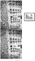
- Figure 7 shows the image recomposition of a scene performed in transform domain, according to a method from the state of the art.
- Figure 8 shows the image recomposition of the same scene performed in measurement domain, using the method of the present invention for obtaining the light field from defocused images.
- the images of Figures 7 and 8 are not normalized to the same signal strength value, it can be seen that the recomposition performed in the measurement domain is better defined and sharper at the edges of the resolution test figures.
- the area marked in the box and enlarged so it can be seen better perfectly illustrates the difference in quality between both retrievals.
Landscapes
- Physics & Mathematics (AREA)
- Spectroscopy & Molecular Physics (AREA)
- General Physics & Mathematics (AREA)
- Engineering & Computer Science (AREA)
- Multimedia (AREA)
- Signal Processing (AREA)
- Investigating Or Analysing Materials By Optical Means (AREA)
- Image Processing (AREA)
- Lenses (AREA)
- Studio Devices (AREA)
- Optics & Photonics (AREA)
Abstract
Description
- The present invention relates to a method for determining the complex amplitude of the electromagnetic field associated with a scene.
- The method of the invention allows optical reconstruction of the scene in its entirety (modulus and phase of the electromagnetic field), which allows the subsequent use thereof in various applications, such as in obtaining the distance map of the scene, representation of the scene in 3D stereo mode or in 3D integral mode, representation of the scene that is completely focused, optically aberrated at will, or corrected for optical distortion (due to change in refractive index).
- The invention can be applied in different technical fields, including computational photography and adaptive optics (astronomy, ophthalmology, microscopy, etc.).
- Up until now, in order to generate a three-dimensional (stereo or integral) image of a scene, the capture of the scene from various viewpoints has been used.
- Orth (Orth, A., & Crozier, K. B. (2013), Light field moment imaging, Optics letters, 38(15), 2666-2668) generates a stereo (non-integral) image from two defocused images, using the light field moment imaging method, working in the transform domain.
- Park (Park, J. H., Lee, S. K., Jo, N. Y., Kim, H. J., Kim, Y. S., & Lim, H. G. (2014), Light ray field capture using focal plane sweeping and its optical reconstruction using 3D displays, Optics Express, 22(21), 25444-25454) proposes a filtered backprojection algorithm applied to the light field such that a 3D stereo and integral image is created from defocused images of the scene. In this case, the defocused images (intensities) are sections at different angles of the light field in transform space. Acquiring few defocused images is the most suitable in low lighting scenarios. However, working in the transform domain with few defocused images causes blurring due to the absence of information in certain spatial frequencies.
- The curvature sensor retrieves the wavefront phase in the pupil from two defocused images. The geometric sensor proposed by Van Dam and Lane (Van Dam, M. A., & Lane, R. G. (2002), Wave-front sensing from defocused images by use of wave-front slopes, Applied optics, 41(26), 5497-5502) also retrieves the wavefront phase in the pupil from two defocused images. However, the measurement of the wavefront phase in the pupil only allows correcting aberrations in the optical axis.
- The preceding problems are solved by means of a method according to
claim 1 and a device according to claim 10. The dependent claims define preferred embodiments of the invention. - A first aspect of the invention defines a method for determining the complex amplitude of the electromagnetic field associated with a scene, comprising the following steps:
- a) capturing a plurality of images of the scene by means of a photographic camera, the images being focused in planes of focus arranged at different distances, wherein the camera comprises a lens of focal length F and a sensor arranged at a certain distance from the lens in its image space,
- b) taking at least one image pair from the plurality of images and determining the accumulated wavefront to the conjugate plane in the object space corresponding to the intermediate plane with respect to the planes of focus of the two images of the pair, determining the wavefront W(x,y) as:

wherein the coefficients dj are determined by means of solving the system of equations:


where fXY is the two-dimensional density function which takes into account the probability of occurrence of a photon and is determined in each case by the normalized intensity I(x,y) of the corresponding image of the pair, i.e.:

- The present invention allows generating not only a three-dimensional image from defocused images of the scene taken from a single viewpoint, but also the tomographic phase distribution of the scene. This means having the electromagnetic field contained in the scene in its entirety without using different viewpoints, as occurs in the plenoptic light field capture cameras, with the subsequent improvement in the final optical resolution obtained, which in the case of plenoptic cameras is limited by the diameter of the subapertures associated with each viewpoint.
- In the context of the invention, it will be understood that a plurality of images is a number of images greater than or equal to two.
- The photographic camera used to capture the images corresponds to a conventional optical system, and it includes a single lens, or system of lenses, working at a fixed or variable focal length (indistinctly), and a sensor arranged at a certain distance from the optical system in the image space.
- The images captured by the camera are conjugate images in different planes. Each includes focused elements (those elements arranged in the plane of focus of the image) and defocused elements (those located in front of and behind the plane of focus).
- According to the method of the invention, each image pair from the plurality of captured images allows determining the accumulated wavefront phase to the turbulence layer conjugated with the acquisition position following the classic rules of converging lenses. Therefore, by subtracting the contribution of each image pair obtained at different conjugate distances, the value of turbulence at that distance, in terms of phase imaging, of wavefront phase map is found. Therefore, when the plurality of images includes only two images, the method of the invention allows obtaining the wavefront in a single plane at a conjugate distance from the associated defocused image pair.
- In a preferred embodiment, the two images of each selected image pair are taken, respectively, on both sides of the focus. In a preferred embodiment, the two images of each selected image pair are taken at symmetrical distances on both sides of the focus. However, the method of the invention is valid for any defocused image pair.
- The method of the invention is a method of turbulence layer-oriented multi-conjugate tomography (Layer-oriented MCAO), based on using defocused images of large objects, instead of using conventional two-dimensional phase sensors such as the Shack-Hartmann or pyramid sensors.
- The method of the present invention allows determining the complex amplitude of the electromagnetic field associated with a scene from the capture of defocused images thereof, even acquired in real time (less than 10 ms in the case of working in the visible range with atmospheric turbulence, 24 images per second in the case of video, etc.) with a single lens and a single viewpoint, without the camera used for the capture having a microlens array in the optical path.
- In one embodiment, the wavefront is determined by the expression:


- Advantageously, in this embodiment the two-dimensional wavefront expanded as a function of complex exponentials is retrieved, which allows directly obtaining the Cartesian distribution of the wavefront phase horizontal and vertical slopes, and therefore the use of conventional slope integration methods, such as Hudgin or Fourier transform filtering.
- In one embodiment, the accumulated wavefront is determined for a plurality of image pairs.
- In one embodiment, the method additionally comprises determining the phase shift between two planes of the object space as the subtraction of the accumulated wavefronts to said planes that have been determined. Preferably, the phase shift is determined for a plurality of planes.
- The present invention allows obtaining the electromagnetic field in its entirety (modulus and phase), not just the intensity thereof, by working with the defocused images in the measurement domain (not in the transform domain), together with a tomographic retrieval of the wavefront phase. Advantageously, the results of working in the measurement domain are defined much better than those of working in the transform domain, where the absence of information in certain spatial frequencies causes blurring when starting from few defocused images. Acquiring few defocused images is most suitable in low lighting scenarios.
- Compared with methods from the state of the art that retrieve the wavefront phase only in the pupil, the present invention has the advantage of tomographically retrieving the wavefront phase that best fits the set of defocused images acquired from a scene. Tomographic measurement of the wavefront phase allows correcting aberrations in the entire field of view of the entrance pupil.
- In one embodiment, the method additionally comprises determining, from P images selected from the plurality of captured images, the value of the light field (L) focused at distance F at M values other than u, M ≤ P, as the values of the light field verifying the system of equations:

obtaining as a result for each image j, with 1 ≤ j ≤ P, the light field LF (x) evaluated at the value of uj resulting from the fit, i.e., the view of the light field corresponding to the value uj , where x and u are the two-dimensional vectors determining the position in the sensor and in the lens of the camera, respectively. - Despite having described determining the light field in combination with the method for determining the wavefront phase according to the first aspect of the invention, the method of determining the light field can be carried out separately. Therefore, an additional aspect of the invention provides a method for determining the light field which comprises:
- a) capturing a plurality of images of the scene by means of a photographic camera, the images being focused in planes of focus arranged at different distances, wherein the camera comprises a lens of focal length F and a sensor arranged a distance from the lens equal to its focal length, and
- b) determining, from P images selected from the plurality of captured images, the value of the light field (L) focused at distance F at M values other than u, M ≤ P, as the values of the light field verifying the system of equations:

obtaining as a result for each image j, with 1 ≤ j ≤ P, the light field LF (x) evaluated at the value of uj resulting from the fit, i.e., the view of the light field corresponding to the value uj , where x and u are the two-dimensional vectors determining the position in the sensor and in the lens of the camera, respectively. - In one embodiment, the value of the light field is determined by solving the system of equations by means of least squares, i.e., minimizing the expression:

- In a second aspect, a device for determining the complex amplitude of the electromagnetic field associated with a scene is defined, comprising
means for capturing images, comprising a lens of focal length F and an image sensor arranged parallel to the lens, at a certain distance from the lens in its image space, and
processing means configured for carrying out step b) of the method according to the first aspect of the invention. - All the features and/or steps of methods described in this specification (including the claims, description and drawings) can be combined in any combination, with the exception of combinations of mutually exclusive features.
- To complement the description made below and for the purpose of helping to better understand the features of the invention according to a preferred practical embodiment thereof, a set of drawings is enclosed as an integral part of said description in which the following is depicted in an illustrative and non-limiting manner:
-
Figures 1 and 2 schematically depict part of the method of the invention. -
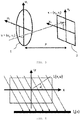
Figure 3 schematically depicts the light field between the lens and the sensor of a camera. -
Figures 4 and5 schematically exemplify a part of the method of the invention. -
Figure 6 schematically depicts obtaining the wavefront phase corresponding to different planes. -
Figures 7 and8 show image recompositions in transform domain and in measurement domain, respectively. - The method of the invention allows retrieving, from two or more defocused images, the Cartesian distribution of the wavefront phase horizontal and vertical slopes in polynomial basis, which in turn allows using any method for phase recomposition from slopes, whether they are zonal methods (Hudgin, etc.) or modal methods. In the case of modal methods, the set of polynomials on which the wavefront phase map is expanded and fitted can be chosen according to the need of the problem: Zernike polynomials (coincide with the classic optical or Seidel aberrations), complex exponentials (contain the Fourier transform kernel, the use of which accelerates computation), Karhunen-Löeve function (without any analytical form but constituting a basis in annular pupils, which are typical in telescopes), etc.
- In general, the method for restoring the phase map from the expansion thereof in a set of polynomials Zj (x,y) comprises considering the wavefront phase at a point (x,y) as follows:

- The horizontal and vertical Cartesian slopes, Sx and Sy respectively, correspond to the following partial derivatives of the wavefront:


- A photon is assumed to displace from a plane -z to a plane +z, and the wavefront at points (x, y) of the intermediate plane is estimated.
- The propagated wavefront intensity is represented by a two-dimensional density function (PDF) for taking into account the probability of occurrence of a photon (denoted as fXY (x, y)), through the corresponding two-dimensional cumulative distribution function (CDF) (denoted as C(x, y)).
- The density function verifies:

- The marginal cumulative distribution function in the variable x is constructed as:


- The property of being a cumulative distribution function in the corresponding variable is conserved for the marginal density function. Therefore,

- Since there is data in planes -z and +z, corresponding to the two images considered, there are two cumulative distribution functions. The marginal cumulative distribution function in plane -z is denoted as C 1X , and the marginal cumulative distribution function in plane +z is denoted as C 2 X.
- Given that the method starts from the values of fXY in planes -z and +z, it is assumed that the data associated with plane -z is defined by fXY and the data associated with plane +z is determined by f 2XY :


- A monotonically increasing sequence of real numbers (s(j)) is considered with 1 ≤ j ≤ T, of values between 0 and 1, i.e., 0 ≤ s(j) ≤ 1 for each 1 ≤ j ≤ T.
- Histogram matching in the marginal cumulative distribution function is performed, to find the mirror image of the values of the cumulative distribution function of the values of s(j). In other words, the value u 1X (j) that meets the following is sought:


- Therefore, u 1X (j) and u 2X (j) have been found for each fixed value of s(j). Graphically speaking, a search is conducted with an x-axis scan of corresponding points, identifying all the ordinates, as schematically depicted in
Figure 1 . - What provides more accurate values is to now go from the density function in the two variables for each of these values, to find, for each value k from 1 to T, the values u 1Y (k) and u 2Y (k) that meet the following:


- Graphically, what is done is to associate each corresponding value on the x-axis with the ordinate that makes the mirror images through the cumulative distribution function match up, as schematically depicted in
Figure 2 . - The result is a two-dimensional mesh of points determined by


- The directional derivatives of the wavefront in the points of the intermediate plane can be considered determined by the expressions:


- Therefore, the system of equations (2) and (3) can be written as:


- The coefficients d of the expansion can be found as the best fit on the plane in the sense of least squares. A preferred way to solve the preceding system is to solve by means of the least squares as:

- Equation (7) can be solved by a number of techniques known by the person skilled in the art, depending on whether or not the matrix ATA is singular.
- In a particular embodiment, the wavefront is expanded as a function of complex exponentials. Expansion is truncated in a certain N ≥ 1 such that it can be written as


- At this point a problem of least squares can be solved with the obtained data because by deriving with respect to x or y, the following is deduced from expression (8)


- Therefore, for each 0 ≤ p, q ≤ N - 1:


- By evaluating at the midpoints, taking into account expressions (4) and (5) and replacing these values in equations (9) and (10), it is possible to arrive at the following overdetermined system:


- In this case, the coefficients of the expansion can be obtained from the expression:

- The method of the invention provides a two-dimensional restoration of the wavefront phase from the defocused images. The obtained wavefront phase corresponds to the accumulated phase differences to the conjugate position in the object space. In other words, if two defocused images are taken that are so far away from the focus of the lens that they almost correspond with images taken in the pupil (or with very little separation from the entrance pupil of the optical system), the phase accumulated in the entire field of view of the scene to the arrival to the objective would be obtained. As the defocused image pair used approaches the focus, the conjugate plane in the object space will correspond to a plane farther away from the entrance pupil, and it will describe the phase accumulated in the scene to that plane.
- The difference between both accumulated phases provides the phase shift present between the farthest plane and the pupil plane of the optical system. Therefore, the greater the number of defocused images used, the more complete the discretization of the object space and the obtained tomographic distribution of the wavefront phase will be. This tomographic distribution of the wavefront phase will have the original two-dimensional optical resolution associated with the capture sensor and the three-dimensional resolution (in optical axis z) that the number of images used allows. It should be pointed out that the three-dimensional resolution does not strictly coincide with the number of planes or defocused images acquired, as it is possible to consider any pair of acquisition planes for obtaining subdiscretization of accumulated wavefront phases, as schematically depicted in
Figure 6 . - With planes Ia and Ib, the accumulated phase W 1(x,y) to the pupil is found. With Ia, and Ib', the accumulated phase W 2(x,y) is found. The difference between W 2 and W 1 provides the phase in the section indicated by the key. By using more planes (more captured images), resolution in axis z of the phase is increased, and a three-dimensional map of the wavefront phase is obtained.
- The method of the present invention can be applied in any technical field in which the wavefront associated with the observation of a scene is to be known, including computational photography and adaptive optics, particularly in applications relating to astronomical observations to obtain a three-dimensional map of turbulences (wavefront phases) associated with a column of the atmosphere, in applications in which it is necessary to correct the view through turbulent media (for example in augmented reality glasses, mobiles, microscopes, or endoscopes), in applications for the tomographic measurement of variations in refractive index in transparent organic tissue samples or in applications of optic communications through turbulent media (atmosphere, ocean, body fluids, etc.).
- The light field L is a four-dimensional representation of the light rays going through the objective of a camera. For the sake of simplicity, a simplified two-dimensional notation will be used. Therefore, LF(x,u) represents the ray going through the main lens of the camera in position u = (u 1, u 2) and arriving at the sensor in position x = (x 1, x2 ) for a camera of focal length F, as depicted in
Figure 3 . - Therefore, there is a four-dimensional volume representing all the rays entering the camera and their positions of arrival to the sensor. Ng (Ng, R., Fourier slice photography, in ACM Transactions on Graphics (TOG), Vol. 24, No. 3, pp. 735-744, ACM, 2005, July) demonstrates that the image that would be projected onto the sensor if said sensor were at distance αF, would correspond to a two-dimensional projection of the light field at angle θ = tan-1(1/ α ) :

Figure 4 . - The method of the invention is based on interpreting Iα (x) as a sum of images at different values u displaced with respect to one another, as schematically depicted in
Figure 5 , and on estimating images at different values u, finding which set of images that are displaced due to a value α' and added to one another best approximates the input image captured with a focus distance Fα'. Displacement in the x dimension (in pixels) is therefore u+(x-u)/α'. - The method comprises estimating the value of the light field focused at distance F (LF ) at M values other than u from P images (I 1(x), I 2(x)...IP (x)) focused at distances α1F, α2F ... αPF and captured with a conventional photographic camera. To that end, the method seeks to find the values of the light field such that the following is met:

- The preceding expression can be simply represented by a linear system of equations of type Ax = b. This system can be solved by finding for x such that it minimizes ∥Ax-b∥2.
- Up until now single channel images have been assumed. In the case of color images (having multiple channels), generating the matrix A once is enough. Then a new vector b containing the information about the images in the channel to be solved is created.
- The method for recomposing the intensity of the image according to the invention allows generating a single image that is completely focused and with complete optical resolution (all-in-focus), generating the all-in-focus stereo pair, generating an all-in-focus multi-stereo image (light field) and generating a light field focused at will where desired, with applications in microscopy, photography, endoscopy, cinematography, etc.
- Assume two images of 8 elements, I1(x) and I2(x), focused at distances α1=2 and α2=4, with F = 1 m. The summation in this case is with indices from n = 1 to n = 2.
- The equations for j = 1 are:


- Expanding:


- In matrix form:

- The resolution of the preceding system provides the values of the light field LF. The values of the light field that are not defined in any equation in the preceding system take the value 0.
-
Figure 7 shows the image recomposition of a scene performed in transform domain, according to a method from the state of the art.Figure 8 shows the image recomposition of the same scene performed in measurement domain, using the method of the present invention for obtaining the light field from defocused images. Although the images ofFigures 7 and8 are not normalized to the same signal strength value, it can be seen that the recomposition performed in the measurement domain is better defined and sharper at the edges of the resolution test figures. The area marked in the box and enlarged so it can be seen better perfectly illustrates the difference in quality between both retrievals.
Claims (11)
- A method for determining the complex amplitude of the electromagnetic field associated with a scene, comprising the following steps:a) capturing a plurality of images of the scene by means of a photographic camera, the images being focused in planes of focus arranged at different distances, wherein the camera comprises a lens or system of lenses of focal length F and a sensor arranged at a certain distance from the lens in the image space,b) taking at least one image pair from the plurality of images and determining the accumulated wavefront to the conjugate plane in the object space corresponding to the intermediate plane with respect to the planes of focus of the two images of the pair, determining the wavefront W(x,y) as:

wherein the coefficients dj are determined by means of solving the system of equations:


where fXY is the two-dimensional density function which takes into account the probability of occurrence of a photon and is determined in each case by the normalized intensity I (x,y) of the corresponding image of the pair, i.e.:

- The method according to claim 1, wherein the wavefront is determined by the expression:


- The method according to any of the preceding claims, which comprises determining the accumulated wavefront for a plurality of image pairs.
- The method according to claim 3, which comprises determining the phase shift between two planes of the object space as the subtraction of the accumulated wavefronts to said planes.
- The method according to claim 4, which comprises determining the phase shift for a plurality of object planes.
- The method according to any of the preceding claims, which additionally comprises:determining, from P images selected from the plurality of captured images, the value of the light field (L) focused at distance F at M values other than u, M ≤ P, as the values of the light field verifying the system of equations:
 where P is the number of images considered for determining the light field, F is the focal length of the lens, LF is the value of the light field focused at distance F, αjF is the focus distance of the image j and Ij (x) is the intensity of the image j, and where [x] denotes the integer closest to x,obtaining as a result for each image j, with 1 ≤ j ≤ P, the light field LF (x) evaluated at the value of uj resulting from the fit, i.e., the view of the light field corresponding to the value uj , where x and u are the two-dimensional vectors determining the position in the sensor and in the lens of the camera, respectively.
 - The method according to claim 6, wherein the value of the light field is determined by solving the system of equations by means of least squares, i.e., minimizing:

- The method according to any of the preceding claims, wherein the two images of each selected image pair are taken, respectively, on both sides of the focus.
- The method according to the preceding claim, wherein the two images of each selected image pair are taken from symmetrical distances on both sides of the focus.
- A device for determining the amplitude of the electromagnetic field associated with a scene, comprising
means for capturing images comprising a lens of focal length F and an image sensor arranged parallel to the lens, at a certain distance from the lens in its image space, and
processing means configured for carrying out step b) of the method according to claim 1. - The device according to claim 10, wherein the processing means are additionally configured for carrying out the actions defined in any of claims 2 to 9.
Applications Claiming Priority (2)
| Application Number | Priority Date | Filing Date | Title |
|---|---|---|---|
| ES201431900A ES2578356B1 (en) | 2014-12-22 | 2014-12-22 | METHOD FOR DETERMINING THE COMPLEX WIDTH OF THE ELECTROMAGNETIC FIELD ASSOCIATED WITH A SCENE |
| PCT/ES2015/070936 WO2016102731A1 (en) | 2014-12-22 | 2015-12-21 | Method for determining the complex amplitude of the electromagnetic field associated with a scene |
Publications (3)
| Publication Number | Publication Date |
|---|---|
| EP3239672A1 true EP3239672A1 (en) | 2017-11-01 |
| EP3239672A4 EP3239672A4 (en) | 2018-09-19 |
| EP3239672B1 EP3239672B1 (en) | 2020-01-15 |
Family
ID=56149310
Family Applications (1)
| Application Number | Title | Priority Date | Filing Date |
|---|---|---|---|
| EP15872012.8A Active EP3239672B1 (en) | 2014-12-22 | 2015-12-21 | Method for determining the complex amplitude of the electromagnetic field associated with a scene |
Country Status (10)
| Country | Link |
|---|---|
| US (1) | US10230940B2 (en) |
| EP (1) | EP3239672B1 (en) |
| JP (1) | JP6600360B2 (en) |
| KR (1) | KR102501402B1 (en) |
| CN (1) | CN107209061B (en) |
| DK (1) | DK3239672T3 (en) |
| ES (1) | ES2578356B1 (en) |
| IL (1) | IL253142B (en) |
| TW (1) | TWI687661B (en) |
| WO (1) | WO2016102731A1 (en) |
Families Citing this family (5)
| Publication number | Priority date | Publication date | Assignee | Title |
|---|---|---|---|---|
| WO2017180615A1 (en) | 2016-04-12 | 2017-10-19 | Quidient, Llc | Quotidian scene reconstruction engine |
| AU2017202910A1 (en) * | 2017-05-02 | 2018-11-22 | Canon Kabushiki Kaisha | Image processing for turbulence compensation |
| US11875476B2 (en) | 2018-05-02 | 2024-01-16 | Quidient, Llc | Codec for processing scenes of almost unlimited detail |
| US10565085B2 (en) * | 2018-06-06 | 2020-02-18 | Sas Institute, Inc. | Two-stage distributed estimation system |
| CN108873363B (en) * | 2018-09-06 | 2023-11-17 | 深圳技术大学(筹) | Three-dimensional light field imaging system and method based on structured light marking |
Family Cites Families (7)
| Publication number | Priority date | Publication date | Assignee | Title |
|---|---|---|---|---|
| US8542421B2 (en) * | 2006-11-17 | 2013-09-24 | Celloptic, Inc. | System, apparatus and method for extracting three-dimensional information of an object from received electromagnetic radiation |
| US8405890B2 (en) * | 2007-01-29 | 2013-03-26 | Celloptic, Inc. | System, apparatus and method for extracting image cross-sections of an object from received electromagnetic radiation |
| ES2372515B2 (en) * | 2008-01-15 | 2012-10-16 | Universidad De La Laguna | CHAMBER FOR THE REAL-TIME ACQUISITION OF THE VISUAL INFORMATION OF THREE-DIMENSIONAL SCENES. |
| CN101939703B (en) | 2008-12-25 | 2011-08-31 | 深圳市泛彩溢实业有限公司 | Hologram three-dimensional image information collecting device and method, reproduction device and method |
| JP2010169976A (en) * | 2009-01-23 | 2010-08-05 | Sony Corp | Spatial image display |
| JP2013519980A (en) * | 2010-02-10 | 2013-05-30 | モチイ,インコーポレイテッド(ディービーエー ヴォクサ) | Aberration corrected dark field electron microscope |
| CN102662238B (en) | 2012-05-03 | 2014-01-15 | 中国科学院长春光学精密机械与物理研究所 | Space optical camera having on-orbit self-diagnosis and compensation functions |
-
2014
- 2014-12-22 ES ES201431900A patent/ES2578356B1/en active Active
-
2015
- 2015-12-21 EP EP15872012.8A patent/EP3239672B1/en active Active
- 2015-12-21 CN CN201580072973.9A patent/CN107209061B/en active Active
- 2015-12-21 JP JP2017533821A patent/JP6600360B2/en active Active
- 2015-12-21 KR KR1020177020020A patent/KR102501402B1/en active IP Right Grant
- 2015-12-21 US US15/538,849 patent/US10230940B2/en active Active
- 2015-12-21 WO PCT/ES2015/070936 patent/WO2016102731A1/en active Application Filing
- 2015-12-21 DK DK15872012.8T patent/DK3239672T3/en active
- 2015-12-22 TW TW104143159A patent/TWI687661B/en active
-
2017
- 2017-06-22 IL IL253142A patent/IL253142B/en unknown
Also Published As
| Publication number | Publication date |
|---|---|
| CN107209061A (en) | 2017-09-26 |
| IL253142A0 (en) | 2017-08-31 |
| CN107209061B (en) | 2020-04-14 |
| DK3239672T3 (en) | 2020-04-14 |
| EP3239672A4 (en) | 2018-09-19 |
| KR102501402B1 (en) | 2023-02-20 |
| US10230940B2 (en) | 2019-03-12 |
| JP6600360B2 (en) | 2019-10-30 |
| TWI687661B (en) | 2020-03-11 |
| JP2018512070A (en) | 2018-05-10 |
| EP3239672B1 (en) | 2020-01-15 |
| ES2578356B1 (en) | 2017-08-04 |
| IL253142B (en) | 2021-07-29 |
| US20180007342A1 (en) | 2018-01-04 |
| WO2016102731A1 (en) | 2016-06-30 |
| KR20170099959A (en) | 2017-09-01 |
| TW201643391A (en) | 2016-12-16 |
| ES2578356A1 (en) | 2016-07-26 |
Similar Documents
| Publication | Publication Date | Title |
|---|---|---|
| EP3239672B1 (en) | Method for determining the complex amplitude of the electromagnetic field associated with a scene | |
| US8432479B2 (en) | Range measurement using a zoom camera | |
| US8305485B2 (en) | Digital camera with coded aperture rangefinder | |
| DK2239706T3 (en) | A method for real-time camera and obtaining visual information of three-dimensional scenes | |
| US8773550B2 (en) | Range measurement using multiple coded apertures | |
| US7531774B2 (en) | Measurement-diverse imaging and wavefront sensing with amplitude and phase estimation | |
| CN110476043B (en) | Method and optical system for acquiring tomographic distribution of wave fronts of electromagnetic fields | |
| Estrada et al. | Multi-frame image fusion using a machine learning-based weight mask predictor for turbulence-induced image degradation | |
| Martinello | Coded aperture imaging | |
| Wang et al. | Parameterized modeling of spatially varying PSF for lens aberration and defocus | |
| Hart et al. | Application of dOTF wavefront sensing to 3D aberration measurement in an optical system | |
| Willson et al. | Tomographic Wave Front Sensing using a Single Imaging Shack-Hartmann Wave Front Sensor and Multi-Frame Blind Deconvolution | |
| Zhang et al. | A fast non-local means algorithm for phase diversity technique to reconstruct high-resolution multi-aperture images |
Legal Events
| Date | Code | Title | Description |
|---|---|---|---|
| STAA | Information on the status of an ep patent application or granted ep patent |
Free format text: STATUS: THE INTERNATIONAL PUBLICATION HAS BEEN MADE |
|
| PUAI | Public reference made under article 153(3) epc to a published international application that has entered the european phase |
Free format text: ORIGINAL CODE: 0009012 |
|
| STAA | Information on the status of an ep patent application or granted ep patent |
Free format text: STATUS: REQUEST FOR EXAMINATION WAS MADE |
|
| 17P | Request for examination filed |
Effective date: 20170706 |
|
| AK | Designated contracting states |
Kind code of ref document: A1 Designated state(s): AL AT BE BG CH CY CZ DE DK EE ES FI FR GB GR HR HU IE IS IT LI LT LU LV MC MK MT NL NO PL PT RO RS SE SI SK SM TR |
|
| AX | Request for extension of the european patent |
Extension state: BA ME |
|
| DAV | Request for validation of the european patent (deleted) | ||
| DAX | Request for extension of the european patent (deleted) | ||
| A4 | Supplementary search report drawn up and despatched |
Effective date: 20180820 |
|
| RIC1 | Information provided on ipc code assigned before grant |
Ipc: G02B 27/22 20060101ALI20180813BHEP Ipc: G01J 11/00 20060101AFI20180813BHEP |
|
| GRAP | Despatch of communication of intention to grant a patent |
Free format text: ORIGINAL CODE: EPIDOSNIGR1 |
|
| STAA | Information on the status of an ep patent application or granted ep patent |
Free format text: STATUS: GRANT OF PATENT IS INTENDED |
|
| INTG | Intention to grant announced |
Effective date: 20190729 |
|
| GRAS | Grant fee paid |
Free format text: ORIGINAL CODE: EPIDOSNIGR3 |
|
| GRAA | (expected) grant |
Free format text: ORIGINAL CODE: 0009210 |
|
| STAA | Information on the status of an ep patent application or granted ep patent |
Free format text: STATUS: THE PATENT HAS BEEN GRANTED |
|
| AK | Designated contracting states |
Kind code of ref document: B1 Designated state(s): AL AT BE BG CH CY CZ DE DK EE ES FI FR GB GR HR HU IE IS IT LI LT LU LV MC MK MT NL NO PL PT RO RS SE SI SK SM TR |
|
| REG | Reference to a national code |
Ref country code: CH Ref legal event code: EP Ref country code: GB Ref legal event code: FG4D |
|
| REG | Reference to a national code |
Ref country code: IE Ref legal event code: FG4D |
|
| REG | Reference to a national code |
Ref country code: DE Ref legal event code: R096 Ref document number: 602015045816 Country of ref document: DE |
|
| REG | Reference to a national code |
Ref country code: AT Ref legal event code: REF Ref document number: 1225551 Country of ref document: AT Kind code of ref document: T Effective date: 20200215 |
|
| REG | Reference to a national code |
Ref country code: DK Ref legal event code: T3 Effective date: 20200409 |
|
| REG | Reference to a national code |
Ref country code: FI Ref legal event code: FGE |
|
| REG | Reference to a national code |
Ref country code: NL Ref legal event code: FP |
|
| REG | Reference to a national code |
Ref country code: LT Ref legal event code: MG4D |
|
| PG25 | Lapsed in a contracting state [announced via postgrant information from national office to epo] |
Ref country code: PT Free format text: LAPSE BECAUSE OF FAILURE TO SUBMIT A TRANSLATION OF THE DESCRIPTION OR TO PAY THE FEE WITHIN THE PRESCRIBED TIME-LIMIT Effective date: 20200607 Ref country code: RS Free format text: LAPSE BECAUSE OF FAILURE TO SUBMIT A TRANSLATION OF THE DESCRIPTION OR TO PAY THE FEE WITHIN THE PRESCRIBED TIME-LIMIT Effective date: 20200115 Ref country code: NO Free format text: LAPSE BECAUSE OF FAILURE TO SUBMIT A TRANSLATION OF THE DESCRIPTION OR TO PAY THE FEE WITHIN THE PRESCRIBED TIME-LIMIT Effective date: 20200415 |
|
| PG25 | Lapsed in a contracting state [announced via postgrant information from national office to epo] |
Ref country code: HR Free format text: LAPSE BECAUSE OF FAILURE TO SUBMIT A TRANSLATION OF THE DESCRIPTION OR TO PAY THE FEE WITHIN THE PRESCRIBED TIME-LIMIT Effective date: 20200115 Ref country code: LV Free format text: LAPSE BECAUSE OF FAILURE TO SUBMIT A TRANSLATION OF THE DESCRIPTION OR TO PAY THE FEE WITHIN THE PRESCRIBED TIME-LIMIT Effective date: 20200115 Ref country code: BG Free format text: LAPSE BECAUSE OF FAILURE TO SUBMIT A TRANSLATION OF THE DESCRIPTION OR TO PAY THE FEE WITHIN THE PRESCRIBED TIME-LIMIT Effective date: 20200415 Ref country code: GR Free format text: LAPSE BECAUSE OF FAILURE TO SUBMIT A TRANSLATION OF THE DESCRIPTION OR TO PAY THE FEE WITHIN THE PRESCRIBED TIME-LIMIT Effective date: 20200416 Ref country code: IS Free format text: LAPSE BECAUSE OF FAILURE TO SUBMIT A TRANSLATION OF THE DESCRIPTION OR TO PAY THE FEE WITHIN THE PRESCRIBED TIME-LIMIT Effective date: 20200515 Ref country code: SE Free format text: LAPSE BECAUSE OF FAILURE TO SUBMIT A TRANSLATION OF THE DESCRIPTION OR TO PAY THE FEE WITHIN THE PRESCRIBED TIME-LIMIT Effective date: 20200115 |
|
| REG | Reference to a national code |
Ref country code: DE Ref legal event code: R097 Ref document number: 602015045816 Country of ref document: DE |
|
| PG25 | Lapsed in a contracting state [announced via postgrant information from national office to epo] |
Ref country code: LT Free format text: LAPSE BECAUSE OF FAILURE TO SUBMIT A TRANSLATION OF THE DESCRIPTION OR TO PAY THE FEE WITHIN THE PRESCRIBED TIME-LIMIT Effective date: 20200115 Ref country code: EE Free format text: LAPSE BECAUSE OF FAILURE TO SUBMIT A TRANSLATION OF THE DESCRIPTION OR TO PAY THE FEE WITHIN THE PRESCRIBED TIME-LIMIT Effective date: 20200115 Ref country code: SM Free format text: LAPSE BECAUSE OF FAILURE TO SUBMIT A TRANSLATION OF THE DESCRIPTION OR TO PAY THE FEE WITHIN THE PRESCRIBED TIME-LIMIT Effective date: 20200115 Ref country code: RO Free format text: LAPSE BECAUSE OF FAILURE TO SUBMIT A TRANSLATION OF THE DESCRIPTION OR TO PAY THE FEE WITHIN THE PRESCRIBED TIME-LIMIT Effective date: 20200115 Ref country code: CZ Free format text: LAPSE BECAUSE OF FAILURE TO SUBMIT A TRANSLATION OF THE DESCRIPTION OR TO PAY THE FEE WITHIN THE PRESCRIBED TIME-LIMIT Effective date: 20200115 Ref country code: ES Free format text: LAPSE BECAUSE OF FAILURE TO SUBMIT A TRANSLATION OF THE DESCRIPTION OR TO PAY THE FEE WITHIN THE PRESCRIBED TIME-LIMIT Effective date: 20200115 Ref country code: SK Free format text: LAPSE BECAUSE OF FAILURE TO SUBMIT A TRANSLATION OF THE DESCRIPTION OR TO PAY THE FEE WITHIN THE PRESCRIBED TIME-LIMIT Effective date: 20200115 |
|
| REG | Reference to a national code |
Ref country code: AT Ref legal event code: MK05 Ref document number: 1225551 Country of ref document: AT Kind code of ref document: T Effective date: 20200115 |
|
| PLBE | No opposition filed within time limit |
Free format text: ORIGINAL CODE: 0009261 |
|
| STAA | Information on the status of an ep patent application or granted ep patent |
Free format text: STATUS: NO OPPOSITION FILED WITHIN TIME LIMIT |
|
| 26N | No opposition filed |
Effective date: 20201016 |
|
| PG25 | Lapsed in a contracting state [announced via postgrant information from national office to epo] |
Ref country code: AT Free format text: LAPSE BECAUSE OF FAILURE TO SUBMIT A TRANSLATION OF THE DESCRIPTION OR TO PAY THE FEE WITHIN THE PRESCRIBED TIME-LIMIT Effective date: 20200115 |
|
| PG25 | Lapsed in a contracting state [announced via postgrant information from national office to epo] |
Ref country code: SI Free format text: LAPSE BECAUSE OF FAILURE TO SUBMIT A TRANSLATION OF THE DESCRIPTION OR TO PAY THE FEE WITHIN THE PRESCRIBED TIME-LIMIT Effective date: 20200115 Ref country code: PL Free format text: LAPSE BECAUSE OF FAILURE TO SUBMIT A TRANSLATION OF THE DESCRIPTION OR TO PAY THE FEE WITHIN THE PRESCRIBED TIME-LIMIT Effective date: 20200115 |
|
| REG | Reference to a national code |
Ref country code: CH Ref legal event code: PL |
|
| PG25 | Lapsed in a contracting state [announced via postgrant information from national office to epo] |
Ref country code: MC Free format text: LAPSE BECAUSE OF FAILURE TO SUBMIT A TRANSLATION OF THE DESCRIPTION OR TO PAY THE FEE WITHIN THE PRESCRIBED TIME-LIMIT Effective date: 20200115 |
|
| PG25 | Lapsed in a contracting state [announced via postgrant information from national office to epo] |
Ref country code: LU Free format text: LAPSE BECAUSE OF NON-PAYMENT OF DUE FEES Effective date: 20201221 |
|
| PG25 | Lapsed in a contracting state [announced via postgrant information from national office to epo] |
Ref country code: LI Free format text: LAPSE BECAUSE OF NON-PAYMENT OF DUE FEES Effective date: 20201231 Ref country code: CH Free format text: LAPSE BECAUSE OF NON-PAYMENT OF DUE FEES Effective date: 20201231 |
|
| PG25 | Lapsed in a contracting state [announced via postgrant information from national office to epo] |
Ref country code: TR Free format text: LAPSE BECAUSE OF FAILURE TO SUBMIT A TRANSLATION OF THE DESCRIPTION OR TO PAY THE FEE WITHIN THE PRESCRIBED TIME-LIMIT Effective date: 20200115 Ref country code: MT Free format text: LAPSE BECAUSE OF FAILURE TO SUBMIT A TRANSLATION OF THE DESCRIPTION OR TO PAY THE FEE WITHIN THE PRESCRIBED TIME-LIMIT Effective date: 20200115 Ref country code: CY Free format text: LAPSE BECAUSE OF FAILURE TO SUBMIT A TRANSLATION OF THE DESCRIPTION OR TO PAY THE FEE WITHIN THE PRESCRIBED TIME-LIMIT Effective date: 20200115 |
|
| PG25 | Lapsed in a contracting state [announced via postgrant information from national office to epo] |
Ref country code: MK Free format text: LAPSE BECAUSE OF FAILURE TO SUBMIT A TRANSLATION OF THE DESCRIPTION OR TO PAY THE FEE WITHIN THE PRESCRIBED TIME-LIMIT Effective date: 20200115 Ref country code: AL Free format text: LAPSE BECAUSE OF FAILURE TO SUBMIT A TRANSLATION OF THE DESCRIPTION OR TO PAY THE FEE WITHIN THE PRESCRIBED TIME-LIMIT Effective date: 20200115 |
|
| PGFP | Annual fee paid to national office [announced via postgrant information from national office to epo] |
Ref country code: GB Payment date: 20231227 Year of fee payment: 9 |
|
| PGFP | Annual fee paid to national office [announced via postgrant information from national office to epo] |
Ref country code: NL Payment date: 20231226 Year of fee payment: 9 Ref country code: IT Payment date: 20231220 Year of fee payment: 9 Ref country code: IE Payment date: 20231227 Year of fee payment: 9 Ref country code: FR Payment date: 20231227 Year of fee payment: 9 Ref country code: FI Payment date: 20231227 Year of fee payment: 9 Ref country code: DK Payment date: 20231229 Year of fee payment: 9 |
|
| PGFP | Annual fee paid to national office [announced via postgrant information from national office to epo] |
Ref country code: BE Payment date: 20231227 Year of fee payment: 9 |
|
| PGFP | Annual fee paid to national office [announced via postgrant information from national office to epo] |
Ref country code: DE Payment date: 20231229 Year of fee payment: 9 |