EP3239588B2 - Method for detecting a substance - Google Patents
Method for detecting a substance Download PDFInfo
- Publication number
- EP3239588B2 EP3239588B2 EP16167511.1A EP16167511A EP3239588B2 EP 3239588 B2 EP3239588 B2 EP 3239588B2 EP 16167511 A EP16167511 A EP 16167511A EP 3239588 B2 EP3239588 B2 EP 3239588B2
- Authority
- EP
- European Patent Office
- Prior art keywords
- tool
- capacitance
- detected
- substance
- set forth
- Prior art date
- Legal status (The legal status is an assumption and is not a legal conclusion. Google has not performed a legal analysis and makes no representation as to the accuracy of the status listed.)
- Active
Links
Images


Classifications
-
- B—PERFORMING OPERATIONS; TRANSPORTING
- B27—WORKING OR PRESERVING WOOD OR SIMILAR MATERIAL; NAILING OR STAPLING MACHINES IN GENERAL
- B27G—ACCESSORY MACHINES OR APPARATUS FOR WORKING WOOD OR SIMILAR MATERIALS; TOOLS FOR WORKING WOOD OR SIMILAR MATERIALS; SAFETY DEVICES FOR WOOD WORKING MACHINES OR TOOLS
- B27G19/00—Safety guards or devices specially adapted for wood saws; Auxiliary devices facilitating proper operation of wood saws
-
- B—PERFORMING OPERATIONS; TRANSPORTING
- B23—MACHINE TOOLS; METAL-WORKING NOT OTHERWISE PROVIDED FOR
- B23Q—DETAILS, COMPONENTS, OR ACCESSORIES FOR MACHINE TOOLS, e.g. ARRANGEMENTS FOR COPYING OR CONTROLLING; MACHINE TOOLS IN GENERAL CHARACTERISED BY THE CONSTRUCTION OF PARTICULAR DETAILS OR COMPONENTS; COMBINATIONS OR ASSOCIATIONS OF METAL-WORKING MACHINES, NOT DIRECTED TO A PARTICULAR RESULT
- B23Q11/00—Accessories fitted to machine tools for keeping tools or parts of the machine in good working condition or for cooling work; Safety devices specially combined with or arranged in, or specially adapted for use in connection with, machine tools
- B23Q11/0078—Safety devices protecting the operator, e.g. against accident or noise
- B23Q11/0082—Safety devices protecting the operator, e.g. against accident or noise by determining whether the operator is in a dangerous position
-
- B—PERFORMING OPERATIONS; TRANSPORTING
- B27—WORKING OR PRESERVING WOOD OR SIMILAR MATERIAL; NAILING OR STAPLING MACHINES IN GENERAL
- B27B—SAWS FOR WOOD OR SIMILAR MATERIAL; COMPONENTS OR ACCESSORIES THEREFOR
- B27B5/00—Sawing machines working with circular or cylindrical saw blades; Components or equipment therefor
- B27B5/29—Details; Component parts; Accessories
- B27B5/38—Devices for braking the circular saw blade or the saw spindle; Devices for damping vibrations of the circular saw blade, e.g. silencing
-
- B—PERFORMING OPERATIONS; TRANSPORTING
- B27—WORKING OR PRESERVING WOOD OR SIMILAR MATERIAL; NAILING OR STAPLING MACHINES IN GENERAL
- B27G—ACCESSORY MACHINES OR APPARATUS FOR WORKING WOOD OR SIMILAR MATERIALS; TOOLS FOR WORKING WOOD OR SIMILAR MATERIALS; SAFETY DEVICES FOR WOOD WORKING MACHINES OR TOOLS
- B27G19/00—Safety guards or devices specially adapted for wood saws; Auxiliary devices facilitating proper operation of wood saws
- B27G19/008—Safety guards or devices specially adapted for wood saws; Auxiliary devices facilitating proper operation of wood saws with sensing of human contact or proximity with the blade
-
- B—PERFORMING OPERATIONS; TRANSPORTING
- B27—WORKING OR PRESERVING WOOD OR SIMILAR MATERIAL; NAILING OR STAPLING MACHINES IN GENERAL
- B27G—ACCESSORY MACHINES OR APPARATUS FOR WORKING WOOD OR SIMILAR MATERIALS; TOOLS FOR WORKING WOOD OR SIMILAR MATERIALS; SAFETY DEVICES FOR WOOD WORKING MACHINES OR TOOLS
- B27G19/00—Safety guards or devices specially adapted for wood saws; Auxiliary devices facilitating proper operation of wood saws
- B27G19/02—Safety guards or devices specially adapted for wood saws; Auxiliary devices facilitating proper operation of wood saws for circular saws
-
- F—MECHANICAL ENGINEERING; LIGHTING; HEATING; WEAPONS; BLASTING
- F16—ENGINEERING ELEMENTS AND UNITS; GENERAL MEASURES FOR PRODUCING AND MAINTAINING EFFECTIVE FUNCTIONING OF MACHINES OR INSTALLATIONS; THERMAL INSULATION IN GENERAL
- F16P—SAFETY DEVICES IN GENERAL; SAFETY DEVICES FOR PRESSES
- F16P3/00—Safety devices acting in conjunction with the control or operation of a machine; Control arrangements requiring the simultaneous use of two or more parts of the body
- F16P3/12—Safety devices acting in conjunction with the control or operation of a machine; Control arrangements requiring the simultaneous use of two or more parts of the body with means, e.g. feelers, which in case of the presence of a body part of a person in or near the danger zone influence the control or operation of the machine
- F16P3/14—Safety devices acting in conjunction with the control or operation of a machine; Control arrangements requiring the simultaneous use of two or more parts of the body with means, e.g. feelers, which in case of the presence of a body part of a person in or near the danger zone influence the control or operation of the machine the means being photocells or other devices sensitive without mechanical contact
- F16P3/148—Safety devices acting in conjunction with the control or operation of a machine; Control arrangements requiring the simultaneous use of two or more parts of the body with means, e.g. feelers, which in case of the presence of a body part of a person in or near the danger zone influence the control or operation of the machine the means being photocells or other devices sensitive without mechanical contact using capacitive technology
-
- G—PHYSICS
- G01—MEASURING; TESTING
- G01V—GEOPHYSICS; GRAVITATIONAL MEASUREMENTS; DETECTING MASSES OR OBJECTS; TAGS
- G01V3/00—Electric or magnetic prospecting or detecting; Measuring magnetic field characteristics of the earth, e.g. declination, deviation
- G01V3/08—Electric or magnetic prospecting or detecting; Measuring magnetic field characteristics of the earth, e.g. declination, deviation operating with magnetic or electric fields produced or modified by objects or geological structures or by detecting devices
Definitions
- the present invention relates to a method for detecting a substance, preferably human tissue, in an environment of a movable tool with the features of the preamble of claim 1, a detection system for carrying out the method and a machine tool with such a detection system.
- a detection system for detecting contact between conductive objects and a saw blade is known. Contacts are detected by detecting a current that flows to the saw blade and to the conductive object that is in contact with the saw blade.
- Disadvantages of methods known from the state of the art are the lack of reliability in detecting a dangerous situation while simultaneously avoiding false detections (so-called "false positives"), the lack of sensitivity or reliability in distinguishing between a workpiece and human tissue, and the lack of reliability or sensitivity in detecting contact between a tool, such as a saw blade, and human tissue.
- implementations of methods known from the state of the art i.e. detection systems for carrying out such methods, are usually associated with the use of additional sensors, such as camera systems, lasers or infrared sensors.
- the object of the present invention is therefore to provide a method for detecting a substance in an environment of a movable tool, which is improved compared to the prior art, a detection system for carrying out the method, and a machine tool with such a detection system.
- the object is achieved according to the invention in that a periodic change in the capacitance is detected, this change being caused by the material being arranged in an area relative to the tool and a geometric property of the tool changing periodically in this area when the tool is moved.
- the area can extend around the material to be detected.
- the area can correspond to a spatial area with a radial distance of several centimeters from the material to be detected around the material.
- a periodic change in the capacitance can be caused by geometric conditions that change periodically at a point - in particular at the point of the smallest normal distance - between the material and the tool when the tool is moved, and this can be detected to detect the material in the vicinity of the movable tool.
- the extent or extent of the area can be related to the sensitivity of the detection of the change in the capacitance.
- the electrode formed by at least a part of the movable tool and the counter electrode electrically insulated from it form a capacitance that can correspond, for example, to a plate capacitor.
- the capacitance depends on the electrode surfaces, the distance between the electrodes and a substance with certain electrical properties, in particular certain dielectric properties, located in the electric field between the electrodes (or in an edge area of the electrodes). Different dielectrics with different permittivities (dielectric constants) can also influence the capacitance.
- the substance to be detected for example human tissue in the form of a body part of a user of the movable tool, can differ from the permittivity of the material to be processed, for example wood, plastic or fiber composite materials.
- a change in the area caused by a movement of the tool, the electrode surface formed by at least part of the tool and/or the distance between the electrode surface formed by at least part of the tool and the counter electrode electrically insulated from it can change on the one hand - in particular locally in the area of the substance to be detected - and/or on the other hand the distance between the electrode surface formed by at least part of the tool and the counter electrode electrically insulated from it can change. This can lead to a periodic change in the capacitance.
- the environment can correspond to an immediate danger area of the tool, in particular a close range of several centimeters to millimeters, in other words an environment in which an undesirable intervention of the tool in the material can take place.
- a geometric property that changes periodically in the area of the material when the tool is moved can be present in a peripheral or edge area of the tool - in particular in an effective area of the tool. Due to its dielectric properties, a substance to be detected in the vicinity of the substance can now influence the electric field prevailing there (in particular an emerging edge field), which can cause a periodic change in the capacitance.
- Such a method is characterized by high reliability and sensitivity in the detection of substances in an environment, especially in the close range of a movable tool. Dangerous situations, such as a user accidentally touching a movable tool, can be detected early and avoided. Defects in the material to be processed, such as nails or other foreign bodies in wood materials, can also be detected. Such a method is also insensitive to external influences, such as contamination by dust, since although these can affect the capacity as a constant component, the periodic component remains essentially unchanged.
- the tool is a cutting tool, preferably a circular saw blade.
- Cutting refers to a mechanical processing method in which material is removed from the material to be processed by the tool.
- cutting tools are saw blades, in particular circular saw blades, or saw blades of band saws or also milling tools, such as end mills or cylindrical milling cutters.
- the geometric property that changes periodically in the area when the tool is moved is given by a cutting geometry of at least one tool cutting edge, in particular by a sequence of saw teeth, and/or at least one material recess and/or at least one material application and/or at least one shape of the tool.
- the tool cutting edge can be understood as the part of the tool that is effective when processing the material.
- An example here is a sequence of saw teeth that define a geometric property of the tool through their tooth height and the tooth gap between individual saw teeth.
- the geometric property that changes periodically in the area around the material is given by the presence or absence of the tool cutting edge, for example a saw tooth, in the area, whereby the electrode surface (by changing the position) and/or the distance of the tool from the material changes periodically in this area. If the tool is designed to be wavy or offset (the cutting edges of the tool are bent), this can also cause a periodic change in the distance of the electrode formed by the tool. If the tool has at least one material recess, for example a material cutout or an indentation, a periodic change in the electrode surface of the tool can also be achieved when the tool is moved.
- the tool cutting edge for example a saw tooth
- a periodic change in the electrode distance and the position of the surface of the electrode formed by the tool can be achieved when the tool is moved. If the tool is designed to be wavy, for example, a periodic change in the electrode surface and/or the electrode distance of the electrode formed by the tool can also be achieved when the tool is moved.
- the movement of the tool can be a guided movement, preferably a rotational movement.
- a guided movement By guiding the movement of the tool, it can be forced into a movement.
- the tool can be brought into action on the material to be processed under mutually determined guidance. Examples of such movements are a rotational movement, a linearly guided movement or a pendulum or pendulum stroke movement.
- the guided movement can also take place periodically.
- the counter electrode is formed by at least a part of a housing in which the tool is arranged in the assembly position and/or an attachment.
- an existing part of the machine tool can be used to form the capacitance, which also means that the use of additional sensors can be dispensed with.
- the counter electrode can be an electrically conductive, for example metallic part of the housing.
- a suitable attachment for example a flat metal part, which can be advantageous in the case of an electrically non-conductive housing, for example.
- the periodicity or frequency can be recorded by recording the period duration. For example, the motor speed of a drive that moves the tool can be recorded.
- the periodicity or frequency can also be recorded, for example, via inductive pickups or light barriers.
- the capacitance is used as a frequency-determining element of an electronic oscillator circuit, preferably an LC oscillator circuit, to detect the change in capacitance.
- An electronic oscillator circuit can be understood as an electronic circuit for generating a periodic alternating voltage with a certain oscillator or oscillation frequency and a certain oscillator or oscillation amplitude of the alternating voltage. Because the capacitance is used as a frequency-determining element of the electronic oscillator circuit, the capacitance can be characterized via the oscillator frequency. If the oscillator circuit is designed as an LC oscillator circuit, the capacitance in conjunction with an inductance (fixed inductance) can form a resonant electrical circuit.
- a frequency modulation of the oscillator frequency of the oscillator circuit caused by the periodic change in the capacitance is recorded for detecting the substance to be detected.
- the capacitance is used as a frequency-determining element of an electronic oscillator circuit, changes in the capacitance lead to changes in the oscillator frequency, with periodic changes in the capacitance in particular leading to periodic changes in the oscillator frequency.
- a frequency modulation of the oscillator frequency resulting in this way is particularly suitable for detecting the substance to be detected, since the occurrence of such a modulation is directly linked to the presence of the substance to be detected in the area of the movable tool and can be used, for example, as an indicator of a dangerous situation (human tissue in the vicinity of the moving tool).
- the frequency modulation can also be advantageous for the frequency modulation to be demodulated using the periodicity of the periodically changing geometric property of the tool. Since the frequency modulation occurs with a modulation frequency that essentially corresponds to the periodicity of the geometric property of the tool that changes periodically when the tool is moved in the area, the presence of the substance to be detected can be detected particularly sensitively and reliably by means of appropriate demodulation.
- the output signal of such an FM demodulation is thus essentially a signal with a signal frequency that corresponds to the periodicity of the geometric property that changes periodically when the tool is moved in the area and an amplitude that correlates with the dielectric properties (permittivity) of the substance to be detected and its proximity to the moving tool. The occurrence of such a signal can be used as a reliable indicator of a dangerous situation.
- an amplitude modulation of the oscillator amplitude of the oscillator circuit is also detected - in particular caused by the tool being touched by the substance to be detected.
- Direct contact of the tool by the substance to be detected causes a damping of the oscillator amplitude, which in the case of a moving tool, analogous to frequency modulation, also results in an amplitude modulation of the oscillator amplitude with essentially the periodicity of the geometric property that changes periodically in the area when the tool is moved.
- a damping or a drop in the oscillator amplitude of the oscillator circuit can thus be used to detect contact of the tool by the substance to be detected.
- the detection of a periodic amplitude modulation or attenuation of the oscillator amplitude of the oscillator circuit can desensitize the process to DC components and can thus increase the tolerance to materials with certain dielectric properties, which are present, for example, in damp wood or weakly conductive materials.
- the amplitude modulation is demodulated using the periodicity of the geometric property of the tool that changes periodically in the area.
- AM demodulation can be carried out and information can be obtained about the contact or contact between the material to be detected and the tool.
- the output signal of the AM demodulation can be a signal with a signal frequency that essentially corresponds to the periodicity of the geometric property that changes periodically in the area when the tool is moved, the signal amplitude of which corresponds to the periodic attenuation. is proportional to the oscillator amplitude.
- the substance to be detected approaches in the far range of the tool, for example when approaching the tool from a distance of several decimetres, there can be a general increase in capacitance and thus a change in the total capacitance of the capacitance.
- This can, for example, detect a rapid approach of the substance to be detected to the tool.
- the rate of change of the change in the total capacitance of the capacitance can be recorded, or a rate of change of an oscillator frequency associated with the capacitance, as well as the sign of the rate of change, can be recorded.
- At least one parameter of the impedance associated with the capacitance is recorded to record the change in capacitance.
- the equivalent series resistance ESR
- the resistance between the tool and the counter electrode that is electrically isolated from it can be effectively recorded, whereby the resistance signal can be used as a reliable indicator of a dangerous situation, in particular to detect contact between the substance and the tool.
- the detection system can have a movable tool and a counter electrode that is electrically insulated from the tool, with the tool and the counter electrode forming a capacitance.
- the tool can also have a geometric property that changes periodically during movement.
- the detection system can also comprise a device for detecting the capacitance formed by the tool and the counter electrode.
- the device can be designed in various ways, for example as described above.
- Such a detection system can enable reliable and sensitive detection of a substance to be detected in an area, in particular in a danger area, of a movable tool.
- Such a detection system is characterized by high reliability and uncomplicated sensor technology.
- Such a machine tool can be designed as a panel saw with, for example, a sliding table and a saw unit.
- Such a machine tool is characterized by high operating safety and reliability.
- only minor structural changes are necessary to design such a machine tool, so that, for example, existing machine tools can also be easily retrofitted or converted.
- Fig.1 shows a highly simplified schematic representation of a machine tool 10 designed as a table saw with a housing 6, a saw table 11 and a tool 2 designed as a circular saw blade.
- the tool 2 is arranged in an opening 12 of the saw table 11 and partially protrudes from it.
- the tool 2 can be driven or moved by a drive 13 arranged in the interior of the housing 6.
- the drive 13 can have, for example, an electric motor and a drive belt.
- the machine tool 10 also has operating elements 15, which can include an on/off switch, selection options for operating modes and status displays.
- a Detection system 8 for carrying out a detection method according to the invention is arranged in a control box 16.
- a danger zone for a user can arise due to the moving tool 2, for example due to a rotating circular saw blade, which is caused by the moving saw teeth 20 of the tool 2 designed as a circular saw blade.
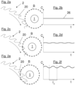
- FIG. 2a a tool 2 designed as a circular saw blade with saw teeth 20 formed on it is shown.
- the movement of the tool here a rotational movement, is stylistically represented by a curved arrow.
- a capacitance 5 is formed by the tool 2 and a counter electrode 4 (not shown here).
- a substance 1 to be detected for example a user's finger, is located in an environment, more precisely in a long-range area, of the saw teeth 20.
- the long-range area can be understood here as a distance of the substance 1 to be detected of a few decimetres from the tool 2.
- the area B shown here in a circle, is shown around the substance 1.
- the area B extends over a certain spatial area around the substance 1.
- the area B corresponds to the peripheral area around the substance 1, within which, when the tool 2 is moved, a change in the capacitance 5 caused by the geometric property of the moving tool 2 changing periodically in the area B can be detected.
- the extent of the region B may be related to the sensitivity of detecting the change in capacitance 5.
- the periodically changing geometric property of the moving tool 2 in area B is shown in the Fig. 2a to 2f by the saw teeth 20, which have a certain surface area and are designed to protrude circumferentially from the tool 2.
- Fig. 2b shows the temporal course of a capacitance signal 26 of the capacitance 5 formed by the tool 2 and the counter electrode 4 (not shown here, see for example Fig. 10). The time is plotted on the abscissa, designated t, and the value C of the capacitance 5 is plotted on the ordinate, designated C.
- the Fig. 2b It can be seen that in the Fig. 2a shown positioning of the substance to be detected in a long-distance area relative to the moving tool 2 does not cause any significant change in the capacitance 5, since here within the area B there is no geometric property of the moving tool 2 which changes periodically during movement.
- the substance to be detected is, however, already in an environment of the moving tool 2 with the saw teeth 20 formed on it, in which a periodic change in the capacitance 5 is caused.
- the area B around the substance 1 to be detected for example a user's finger, there are parts of the saw teeth 20.
- the area B can here comprise an area around the substance 1 to be detected of a few centimeters or millimeters from the tool 2.
- a material 1 is shown which is directly approaching the tool 2, whereby the movement of the tool 2 causes the tool cutting edges formed thereon in the form of saw teeth 20 (or also the gaps between the tool cutting edges) to move past the material 1 within the area B.
- a periodic change in the capacitance 5 is caused by the local (i.e. related to the area B) periodically changing position of the electrode surface of the tool 2, as is also the case in Fig. 2f is illustrated.
- Fig. 2f It can also be seen that the further approach of the material 1 to the tool 2 has led to a change (increase) in the total capacity of the capacity 5.
- the periodically changing portion of the capacity 5 has a period T Z which is inversely proportional to the periodicity f Z.
- the period T Z essentially corresponds to the time required between the movement past of a sawtooth 20 and a sawtooth following it on the material 1. Due to the direct approach, for example to a distance of a few millimeters, of the material 1 to the sawteeth 20 of the tool 2, the periodic change in the capacity 5 caused thereby is particularly pronounced.
- FIG. 3a to 3f is one of the Figures 2a to 2f
- An analogous situation is shown, but here, in addition to the material 1, a material 3 to be processed by the tool 2 is shown.
- the material 1 and the material 3 to be processed can have different electrical properties, in particular different dielectric properties.
- the material 1 has a first permittivity ⁇ 1 and the material 3 a second permittivity ⁇ 2.
- ⁇ 1 , ⁇ 2 With different permittivities ⁇ 1 , ⁇ 2 , the material 1 and the tool 2 therefore have different influences on electrical fields. These different influences on electrical fields can be used to distinguish a material 1 from a material 3 in an environment of tool 2.
- Fig. 3a a material 3 engaging with the tool 2 and a material 1 located at a certain distance from the tool 2 are shown.
- the area B around the material 1 is shown.
- the relative permittivities of human tissue and wood differ by a factor of around 20, which also has a corresponding effect on the size of the change in the capacitance.
- an approach of a material 3 with a low permittivity ⁇ 2 will also cause a periodic change in the capacitance 5, but in practice this can be neglected compared to the periodic change in the capacitance 5 caused by a substance 1 to be detected with a high permittivity ⁇ 1 .
- Fig. 3c the processed material 3 and the material 1 to be detected are shown after a further approach to the moving tool 2. Parts of the tool 2 penetrate into the area B.
- the Fig. 3d From the curve of the value of capacitance 5 shown, it can be seen that the total capacity of capacitance 5 has been increased overall by the approach of substance 1 and material 3 and now also has a periodically changing component caused by the proximity of substance 1.
- Fig. 4a a situation is shown in which the material 1 to be detected is approaching the moving tool 2 without touching it (or the envelope).
- Fig. 4b The temporal progression of the value of the effective series resistance shown is thus essentially unaffected by the presence of substance 1 and is therefore constant.
- Fig. 4c a situation is shown in which the material 1 to be detected is so close to the moving tool 2 that the saw teeth 20 formed on it contact the material 1 as it moves past, but do not engage it to any significant extent.
- Fig. 4d From the temporal progression of the equivalent series resistance shown, it can be seen that this is periodically changed significantly when the tool 2 comes into contact with the material 1. In this way, the detection of a characteristic value of the impedance associated with the capacitance 5, in particular when the equivalent series resistance of the capacitance 5 is detected, can reliably and with high sensitivity detect a contact of the tool 2 with the material 1 to be detected.
- Fig. 4e an approach of the material 1 to the moving tool 2 is shown, in which the saw teeth 20 formed on the tool 2 can already clearly engage with the material 1.
- Fig. 4f Such contact or intervention can be clearly seen from the temporal progression of the equivalent series resistance of the capacitor 5.
- the change in the equivalent series resistance of the capacitor 5 caused by the contact of the material 1 with the tool 2 can be caused on the one hand by a capacitive coupling of the material 1 to the counter electrode 4 of the capacitor 5 that exists even without contact (series connection of the capacitors or also by an electrically conductive connection that may be created between the tool 2 forming an electrode of the capacitor 5 and the material 1 referenced to a certain electrical potential (e.g. earth potential).
- a certain electrical potential e.g. earth potential
- FIG. 5a an approach of the material 1 to a moving tool 2 with different approach speeds v1, v2 from the far area is shown.
- a stationary substance 1 to be detected for example a user’s hand, is shown at some distance, for example a few decimetres, from the moving tool 2.
- the Fig. 5b The time course of the value C of the capacitance 5 shown is constant due to the constant distance.
- Fig. 5c an approach of the material 1 to the moving tool 2 with a first approach speed v1 is shown.
- Fig. 5d is the resulting increase in the value of the capacity 5.
- the slope of the capacity curve is proportional to the approach speed.
- Fig. 5e Analogously, in Fig. 5e the approach of a material 1 to a moving tool 2 with a second, higher approach speed v2 is shown.
- the Fig. 5f The temporal progression of the value of the capacitance 5 shown is correspondingly steeper. The faster the approach, the greater the gradient of the changing value. In this way, in addition to the presence of a substance 1 in a close range of the tool 2, an approach of a substance 1 to be detected to the tool 2 in a far range can be detected.
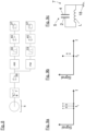
- FIG. 6a a design of the tool 2 with material recesses 21 is shown, through which the geometric property that changes periodically in the area B when the tool 2 moves is given.
- a design of the tool 2 can be suitable for segmented grinding wheels, for example.
- Fig. 6b As shown, even with a tool 2 designed in this way, a periodic change in the capacitance 5 is caused in the presence of a substance to be detected.
- Fig. 6c a design of the tool 2 with material recesses 21, for example holes, is shown.
- Fig. 6c a design of the tool 2 with material recesses 21, for example holes, is shown.
- a tool 2 designed in this way can also cause a periodic change in the capacitance 5 in the presence of a substance 1 to be detected.
- a design can be suitable, for example, for peripheral grinding wheels or for saw blades with very fine teeth.
- a tool 2 which has material deposits 22, for example material deposits 22 protruding axially from the tool 2 or holes in the tool 2 filled with a certain material.
- a periodic change in the capacitance 5 can also be caused in a tool 2 designed in this way in the presence of a substance 1 to be detected.
- 6g is shown an embodiment of a tool 2 with geometric properties given by formations 23 of the tool 2, which change periodically when the tool 2 moves.
- a top view and a side view of the tool 2 as shown in the other figures are shown.
- a peripheral area of the tool 2 can be designed to be wavy.
- Fig. 6h As shown, even with a tool 2 designed in this way, a periodic change in the capacitance can be induced in the presence of a substance to be detected.
- a capacitance 5 with a radial and azimuthal (or polar) inhomogeneous electric field can be formed by the tool 2 and the counter electrode 4 formed in isolation from it.
- the course of the field or the inhomogeneities of the field can correspond to the shape (and possibly periodicity) of the tool geometry.
- the inhomogeneous electric field can be transported along with the tool 2 and, if a substance 1 is present in the environment or in the electric field of the tool 2, a change in the capacitance 5 corresponding to the inhomogeneities of the field (possibly periodic) can be caused and recorded.
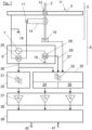
- FIG.7 a block diagram of an embodiment of a detection system 8 for carrying out a method for detecting a substance 1 is shown.
- the detection system 8 has a capacitance 5, which is formed by a tool 2 forming a first electrode and a saw table 11 forming a counter electrode 4, and a device 9 for detecting the capacitance 5.
- the saw table 11 is grounded via the ground connection 18 and is thus electrically connected to the ground potential.
- the tool 2 mounted on the saw shaft 14 of a drive 13 (not shown here) partially protrudes from an opening 12 in the saw table 11.
- the tool 2 is contacted to the saw shaft 14 via a contact 17, for example a sliding contact.
- the device 9 for detecting the capacitance 5 has, in the embodiment shown, an oscillator circuit 7, a device for capacitance detection 25 and a device for impedance detection 28.
- the capacitance 5 can be used as a frequency-determining element.
- a capacitance signal 26 can be output by the capacitance detection device 25.
- a frequency detection device 19 can also be provided, which outputs a frequency signal 27.
- the devices shown in addition to the detection system 8 serve to further process the signals output by the device 9 for detecting the capacitance 5.
- the device for proximity detection 30 can first detect an approach of a material 1 to a moving tool 2, as is the case, for example, in the Figures 5a to 5f shown.
- a bandpass filter 31 can be used to set an upper and lower limit frequency for the Capacitance signal 26 can be determined.
- the output signal of the device for proximity detection 30 can correspond to the approach speed v1, v2.
- the further device for proximity detection 32 serves to detect an approach of a material 1 to the movable tool 2 in a close range of the tool 2, as is the case, for example, in the Figures 2a to 2f or 3a to 3f.
- a bandpass filter 33 can also be used here.
- the incoming signals can go through a capacitance evaluation 34 or a resistance evaluation 35, with the output signals characterizing an approach or contact of the substance 1 to be detected to the tool 2.
- a threshold detection device 36 with threshold detectors 37 can define signal levels from which a switching signal is delivered at the output of the threshold detection device 36. These threshold values can be used to set danger thresholds, whereby, for example, a maximum permissible approach speed v1, v2 or a maximum permissible approach of the substance 1 to be detected to the tool 2 can be set.
- the signals output by the threshold detection device 36 can finally be evaluated by an evaluation logic 38 depending on the operating state of the machine tool 10, which can be characterized by input signals 41.
- the evaluation logic 38 can also initiate desired protective measures by setting output signals 42 accordingly.
- Fig.8 a block diagram of an analog variant of a part of the detection system 8 is shown.
- the variant shown comprises a capacitor 5, an oscillator circuit 7 operated with it and two parallel demodulation branches for characterizing the capacitor 5.
- the capacitor 5 is as in Fig. 9c illustrated by a tool 2 and a counter electrode 4.
- the counter electrode 4 can be connected to the ground potential via a ground connection 18.
- this forms in the Fig.8 shown embodiment comprises a frequency-determining part of an oscillator circuit 7, which has an inductance L in addition to the capacitance 5.
- This inductance L can be designed, for example, in the form of a primary winding of a transmitter or transformer.
- an AM demodulator AM follows on the output side of a high-frequency amplifier 39 and, in parallel, an FM demodulator FM. If the capacitance 5 changes as described above, there is a change in the oscillator frequency or oscillator amplitude, which can be detected by the demodulation branches. This is shown in the Fig. 9a and 9b illustrated.
- Fig. 9a shows the case of a frequency modulation of the oscillator frequency of the oscillator circuit 7 in a frequency representation.
- the abscissa marked f represents the frequency axis and the ordinate marked signal represents the amplitude of the oscillator circuit 7.
- a first oscillator frequency f 1 with a given amplitude is initially established. In the frequency image of the Fig. 9a this corresponds to a signal at f 1 .
- the signal In the case of a (monotonic) approach of a substance 1 to be detected to the tool 2 from a distant area, the signal would move (monotonic) in one direction along the frequency axis, which could also be detected by FM demodulation in the form of a (montonically) changing signal.
- An alternating voltage signal with the periodicity f z can advantageously be used as the reference frequency for demodulation.
- a bandpass filter 33 that is permeable at the periodicity f z can be used to specifically monitor the occurrence of a signal caused by the periodic change in the capacitance 5. This can result in the detection method being highly stable with respect to interference and DC components.
- An AC amplifier 40 can then supply the filtered output signal to a threshold detector 37.
- the oscillator amplitude may initially be dampened. If the intervention continues, the material 1 may periodically come into contact with the tool 2.
- AM demodulation of the modulated output signal of the oscillator circuit 7 can now also be carried out. In this way, an alternating voltage signal can be obtained from an amplitude modulation of the oscillator amplitude, the occurrence and amplitude of which are directly related to contact between the material 1 to be detected and the tool 2.
- Fig. 9b shows the case of an amplitude modulation of the oscillator amplitude occurring at the periodicity f z .
- a bandpass filter 33 can be used to ensure that the demodulated signal occurs at the periodicity f z . This allows the detection of contact between the tool 2 and the material 2 reliably and with high sensitivity.
- an AC amplifier 40 can supply the filtered output signal to a threshold detector 37.
Landscapes
- Engineering & Computer Science (AREA)
- Mechanical Engineering (AREA)
- Life Sciences & Earth Sciences (AREA)
- Wood Science & Technology (AREA)
- Forests & Forestry (AREA)
- General Engineering & Computer Science (AREA)
- Investigating Or Analyzing Materials By The Use Of Electric Means (AREA)
- Geophysics And Detection Of Objects (AREA)
- Measurement Of Length, Angles, Or The Like Using Electric Or Magnetic Means (AREA)
- Saccharide Compounds (AREA)
Description
Die vorliegende Erfindung betrifft ein Verfahren zur Detektion eines Stoffs, vorzugsweise von menschlichem Gewebe, in einem Umfeld eines bewegbaren Werkzeugs mit den Merkmalen des Oberbegriffs des Anspruchs 1, ein Detektionssystem zur Durchführung des Verfahrens sowie eine Werkzeugmaschine mit einem solchen Detektionssystem.The present invention relates to a method for detecting a substance, preferably human tissue, in an environment of a movable tool with the features of the preamble of
Aus dem Stand der Technik sind Verfahren zur Detektion von Stoffen in einem Umfeld eines bewegbaren Werkzeugs bekannt, wie beispielsweise aus der
Aus der
Aus der
Nachteilig an aus dem Stand der Technik bekannten Verfahren sind dabei die mangelnde Zuverlässigkeit bei Erkennung einer Gefahrensituation bei gleichzeitiger Vermeidung von Fehlerkennungen (sogenannten "false positives"), die mangelnde Empfindlichkeit bzw. Zuverlässigkeit bei der Unterscheidung zwischen einem Werkstück und menschlichem Gewebe, sowie die mangelnde Zuverlässigkeit bzw. Empfindlichkeit bei der Detektion einer Berührung eines Werkzeugs, beispielsweise eines Sägeblatts, durch menschliches Gewebe. Zudem sind Umsetzungen von aus dem Stand der Technik bekannten Verfahren, also Detektionssysteme zur Durchführung solcher Verfahren, gewöhnlich mit dem Einsatz von zusätzlichen Sensoren, wie z. B. Kamerasystemen, Lasern oder Infrarotsensoren, verbunden.Disadvantages of methods known from the state of the art are the lack of reliability in detecting a dangerous situation while simultaneously avoiding false detections (so-called "false positives"), the lack of sensitivity or reliability in distinguishing between a workpiece and human tissue, and the lack of reliability or sensitivity in detecting contact between a tool, such as a saw blade, and human tissue. In addition, implementations of methods known from the state of the art, i.e. detection systems for carrying out such methods, are usually associated with the use of additional sensors, such as camera systems, lasers or infrared sensors.
Dementsprechend aufwändig gestaltet sind die dadurch nötigen baulichen Änderungen an Werkzeugmaschinen mit solchen Detektionssystemen.The necessary structural changes to machine tools with such detection systems are correspondingly complex.
Aufgabe der vorliegenden Erfindung ist es daher, ein gegenüber dem Stand der Technik verbessertes Verfahren zur Detektion eines Stoffs in einem Umfeld eines bewegbaren Werkzeugs, ein Detektionssystem zur Durchführung des Verfahrens, sowie eine Werkzeugmaschine mit einem solchen Detektionssystem anzugeben.The object of the present invention is therefore to provide a method for detecting a substance in an environment of a movable tool, which is improved compared to the prior art, a detection system for carrying out the method, and a machine tool with such a detection system.
Insbesondere sollen die oben genannten Nachteile hinsichtlich der Zuverlässigkeit, Empfindlichkeit und Komplexität behoben werden.In particular, the above-mentioned disadvantages regarding reliability, sensitivity and complexity should be eliminated.
Die gestellte Aufgabe wird durch ein Verfahren mit den Merkmalen des Anspruchs 1, ein Detektionssystem mit den Merkmalen des Anspruchs 13 sowie einer Werkzeugmaschine mit einem solchen Detektionssystem gelöst. Vorteilhafte Ausführungsformen der Erfindung sind in den abhängigen Ansprüchen definiert.The stated object is achieved by a method having the features of
Die Aufgabe wird erfindungsgemäß dadurch gelöst, dass eine periodische Änderung der Kapazität erfasst wird, wobei diese Änderung dadurch hervorgerufen wird, dass der Stoff in einem Bereich relativ zum Werkzeug angeordnet ist und sich bei einer Bewegung des Werkzeugs eine geometrische Eigenschaft des Werkzeugs in diesem Bereich periodisch ändert. Der Bereich kann sich dabei um den zu detektierenden Stoff herum erstrecken. So kann der Bereich also beispielsweise einem Raumbereich mit einem radialen Abstand vom zu detektierenden Stoff von mehreren Zentimetern um den Stoff herum entsprechen. Mit anderen Worten kann durch sich bei Bewegung des Werkzeugs periodisch ändernde geometrische Verhältnisse an einem Punkt - insbesondere am Punkt des geringsten Normalabstandes - zwischen Stoff und Werkzeug eine periodische Änderung der Kapazität hervorgerufen werden und diese zur Detektion des Stoffs im Umfeld des bewegbaren Werkzeugs erfasst werden. Die Ausdehnung bzw. Erstreckung des Bereichs kann mit der Empfindlichkeit der Erfassung der Änderung der Kapazität zusammenhängen.The object is achieved according to the invention in that a periodic change in the capacitance is detected, this change being caused by the material being arranged in an area relative to the tool and a geometric property of the tool changing periodically in this area when the tool is moved. The area can extend around the material to be detected. For example, the area can correspond to a spatial area with a radial distance of several centimeters from the material to be detected around the material. In other words, a periodic change in the capacitance can be caused by geometric conditions that change periodically at a point - in particular at the point of the smallest normal distance - between the material and the tool when the tool is moved, and this can be detected to detect the material in the vicinity of the movable tool. The extent or extent of the area can be related to the sensitivity of the detection of the change in the capacitance.
Die von zumindest einem Teil des bewegbaren Werkzeugs ausgebildete Elektrode und die von diesem elektrisch isolierte Gegenelektrode bilden dabei eine Kapazität aus, die beispielsweise einem Plattenkondensator entsprechen kann. Die Kapazität hängt von den Elektrodenflächen, dem Abstand der Elektroden sowie einem sich im elektrischen Feld zwischen den (bzw. in einem Randbereich der) Elektroden befindenden Stoff mit bestimmten elektrischen Eigenschaften, insbesondere bestimmten dielektrischen Eigenschaften, ab. Dabei können auch unterschiedliche Dielektrika mit unterschiedlichen Permittivitäten (Dielektrizitätskonstanten) Einfluss auf die Kapazität nehmen. So kann sich beispielsweise der zu detektierende Stoff, beispielsweise menschliches Gewebe in Form eines Körperteils eines Benutzers des bewegbaren Werkzeugs, von der Permittivität des zu bearbeitenden Werkstoffs, beispielsweise Holz, Kunststoff oder Faserverbundwerkstoffe, unterscheiden. Wird also eine Änderung der Kapazität detektiert, so kann ein Rückschluss auf die Veränderung der relativen Permittivität, also auf die Anwesenheit eines Stoffs, gezogen werden. Durch eine sich in dem Bereich durch eine Bewegung des Werkzeugs periodisch ändernde geometrische Eigenschaft kann sich nun einerseits - insbesondere lokal im Bereich des zu detektierenden Stoffs - die von zumindest einem Teil des Werkzeugs ausgebildete Elektrodenfläche und/oder andererseits der Abstand der von zumindest einem Teil des Werkzeugs ausgebildeten Elektrodenfläche zur elektrisch von dieser isolierten Gegenelektrode ändern. Dies kann zu einer periodischen Änderung der Kapazität führen. Bei Anwesenheit des zu detektierenden Stoffs in einem Bereich des Werkzeugs, in welchem die sich periodisch ändernde geometrische Eigenschaft auftritt, wird somit eine verstärkte periodische Änderung der Kapazität hervorgerufen. Das Umfeld kann dabei einem unmittelbaren Gefahrenbereich des Werkzeugs, also insbesondere ein Nahbereich von mehreren Zentimetern bis Millimetern, entsprechen, also einem Umfeld, in welchem ein unerwünschter Eingriff des Werkzeugs in den Stoff stattfinden kann. Allgemein kann eine sich in dem Bereich des Stoffs bei Bewegung des Werkzeugs periodisch ändernde geometrische Eigenschaft in einem Umfangs- bzw. Randbereich des Werkzeugs - insbesondere in einem Wirkbereich des Werkzeugs - gegeben sein. Durch einen sich in einem Umfeld davon befindenden, zu detektierenden Stoff kann nun aufgrund dessen dielektrischer Eigenschaften Einfluss auf das dort herrschende elektrische Feld (insbesondere auf ein austretendes Randfeld) genommen werden, wodurch eine periodische Änderung der Kapazität hervorgerufen werden kann.The electrode formed by at least a part of the movable tool and the counter electrode electrically insulated from it form a capacitance that can correspond, for example, to a plate capacitor. The capacitance depends on the electrode surfaces, the distance between the electrodes and a substance with certain electrical properties, in particular certain dielectric properties, located in the electric field between the electrodes (or in an edge area of the electrodes). Different dielectrics with different permittivities (dielectric constants) can also influence the capacitance. For example, the substance to be detected, for example human tissue in the form of a body part of a user of the movable tool, can differ from the permittivity of the material to be processed, for example wood, plastic or fiber composite materials. If a change in the capacitance is detected, a conclusion can be drawn about the change in the relative permittivity, i.e. the presence of a substance. A change in the area caused by a movement of the tool, the electrode surface formed by at least part of the tool and/or the distance between the electrode surface formed by at least part of the tool and the counter electrode electrically insulated from it can change on the one hand - in particular locally in the area of the substance to be detected - and/or on the other hand the distance between the electrode surface formed by at least part of the tool and the counter electrode electrically insulated from it can change. This can lead to a periodic change in the capacitance. If the substance to be detected is present in an area of the tool in which the periodically changing geometric property occurs, an increased periodic change in the capacitance is thus caused. The environment can correspond to an immediate danger area of the tool, in particular a close range of several centimeters to millimeters, in other words an environment in which an undesirable intervention of the tool in the material can take place. In general, a geometric property that changes periodically in the area of the material when the tool is moved can be present in a peripheral or edge area of the tool - in particular in an effective area of the tool. Due to its dielectric properties, a substance to be detected in the vicinity of the substance can now influence the electric field prevailing there (in particular an emerging edge field), which can cause a periodic change in the capacitance.
Ein solches Verfahren zeichnet sich durch hohe Zuverlässigkeit und Empfindlichkeit bei der Erkennung von Stoffen in einem Umfeld, insbesondere in einem Nahbereich, eines bewegbaren Werkzeugs aus. Dabei können Gefahrensituationen, wie etwa das ungewollte Berühren eines bewegbaren Werkzeugs durch einen Benutzer, frühzeitig erkannt und vermieden werden. Auch lassen sich Fehlstellen im zu bearbeitenden Werkstoff, wie etwa Nägel oder andere Fremdkörper in Holzwerkstoffen, erkennen. Auch ist ein solches Verfahren unempfindlich gegenüber äußerer Einflüsse, wie etwa Verschmutzungen durch Staub, da sich diese zwar als Gleichanteil auf die Kapazität auswirken können, jedoch den periodischen Anteil im Wesentlichen unverändert lassen.Such a method is characterized by high reliability and sensitivity in the detection of substances in an environment, especially in the close range of a movable tool. Dangerous situations, such as a user accidentally touching a movable tool, can be detected early and avoided. Defects in the material to be processed, such as nails or other foreign bodies in wood materials, can also be detected. Such a method is also insensitive to external influences, such as contamination by dust, since although these can affect the capacity as a constant component, the periodic component remains essentially unchanged.
Dabei kann vorgesehen sein, dass das Werkzeug ein zerspanendes Werkzeug, vorzugsweise ein Kreissägeblatt, ist. Zerspanen bezeichnet dabei ein mechanisches Bearbeitungsverfahren, bei denen Material von dem zu bearbeitenden Werkstoff durch das Werkzeug abgetragen wird. Beispiele für zerspanende Werkzeuge sind Sägeblätter, insbesondere Kreissägeblätter, oder Sägebänder von Bandsägen oder auch Fräswerkzeuge, wie Schaftfräser oder Walzenfräser.It can be provided that the tool is a cutting tool, preferably a circular saw blade. Cutting refers to a mechanical processing method in which material is removed from the material to be processed by the tool. Examples of cutting tools are saw blades, in particular circular saw blades, or saw blades of band saws or also milling tools, such as end mills or cylindrical milling cutters.
Dabei kann auch vorgesehen sein, dass die sich in dem Bereich bei Bewegung des Werkzeugs periodisch ändernde geometrische Eigenschaft durch eine Schneidengeometrie zumindest einer Werkzeugschneide, insbesondere durch eine Abfolge von Sägezähnen, und/oder zumindest eine Materialaussparung und/oder zumindest eine Materialauftragung und/oder zumindest eine Ausformung des Werkzeugs gegeben ist. Als Werkzeugschneide kann dabei der bei der Bearbeitung des Werkstoffs wirksame Teil des Werkzeugs verstanden werden. Als Beispiel kann hier eine Abfolge von Sägezähnen genannt werden, welche durch ihre Zahnhöhe und die zwischen einzelnen Sägezähnen bestehende Zahnlücke eine geometrische Eigenschaft des Werkzeugs definieren. Bei einer Bewegung eines so ausgebildeten Werkzeugs ist die sich in dem Bereich um den Stoff periodisch ändernde geometrische Eigenschaft durch die An- bzw. Abwesenheit der Werkzeugschneide, also beispielsweise eines Sägezahns, in dem Bereich gegeben, wodurch sich die Elektrodenfläche (durch Änderung der Lage) und/oder der Abstand des Werkzeugs zum Stoff in diesem Bereich periodisch ändert. Bei einer gewellten bzw. geschränkten (Ausbiegung der Werkzeugschneiden) Ausbildung des Werkzeugs kann dies zusätzlich eine periodische Änderung des Abstands der vom Werkzeug ausgebildeten Elektrode bewirken. Bei zumindest einer Materialaussparung des Werkzeugs, beispielsweise einer Materialausnehmung bzw. einer Einbuchtung, kann bei Bewegung des Werkzeugs ebenfalls eine periodische Änderung der Elektrodenfläche des Werkzeugs erreicht werden. Durch eine Materialauftragung kann bei einer Bewegung des Werkzeugs beispielsweise eine periodische Änderung des Elektrodenabstands und der Lage der Fläche der vom Werkzeug ausgebildeten Elektrode erreicht werden. Bei einer Ausformung des Werkzeugs, beispielsweise bei einer welligen Ausführung des Werkzeugs, kann ebenso bei Bewegung des Werkzeugs eine periodische Änderung der Elektrodenfläche und/oder des Elektrodenabstands der von dem Werkzeug ausgebildeten Elektrode erreicht werden.It can also be provided that the geometric property that changes periodically in the area when the tool is moved is given by a cutting geometry of at least one tool cutting edge, in particular by a sequence of saw teeth, and/or at least one material recess and/or at least one material application and/or at least one shape of the tool. The tool cutting edge can be understood as the part of the tool that is effective when processing the material. An example here is a sequence of saw teeth that define a geometric property of the tool through their tooth height and the tooth gap between individual saw teeth. When a tool designed in this way moves, the geometric property that changes periodically in the area around the material is given by the presence or absence of the tool cutting edge, for example a saw tooth, in the area, whereby the electrode surface (by changing the position) and/or the distance of the tool from the material changes periodically in this area. If the tool is designed to be wavy or offset (the cutting edges of the tool are bent), this can also cause a periodic change in the distance of the electrode formed by the tool. If the tool has at least one material recess, for example a material cutout or an indentation, a periodic change in the electrode surface of the tool can also be achieved when the tool is moved. By applying material, for example, a periodic change in the electrode distance and the position of the surface of the electrode formed by the tool can be achieved when the tool is moved. If the tool is designed to be wavy, for example, a periodic change in the electrode surface and/or the electrode distance of the electrode formed by the tool can also be achieved when the tool is moved.
Grundsätzlich kann vorgesehen sein, dass die Bewegung des Werkzeugs eine geführte Bewegung, vorzugsweise eine Rotationsbewegung, ist. Durch die Führung der Bewegung des Werkzeugs kann dieses in eine Zwangsbewegung versetzt werden. So kann das Werkzeug am zu bearbeitenden Werkstoff unter gegenseitig bestimmter Führung zur Wirkung gebracht werden. Beispiele für solche Bewegungen sind etwa eine Rotationsbewegung, eine linear geführte Bewegung oder eine Pendel- bzw. Pendelhubbewegung. Die geführte Bewegung kann auch periodisch ablaufen.In principle, the movement of the tool can be a guided movement, preferably a rotational movement. By guiding the movement of the tool, it can be forced into a movement. In this way, the tool can be brought into action on the material to be processed under mutually determined guidance. Examples of such movements are a rotational movement, a linearly guided movement or a pendulum or pendulum stroke movement. The guided movement can also take place periodically.
Auch kann vorgesehen sein, dass die Gegenelektrode von zumindest einem Teil eines Gehäuses, in welchem das Werkzeug in Montagelage angeordnet ist, und/oder einem Anbauteil ausgebildet wird. Durch eine Ausbildung der Gegenelektrode von einem Teil des Gehäuses, in welchem das Werkzeug in Montagelage angeordnet ist, kann ein bestehender Teil der Werkzeugmaschine zur Ausbildung der Kapazität herangezogen werden, wodurch auch auf den Einsatz von zusätzlichen Sensoren verzichtet werden kann. Als Gegenelektrode kann sich dabei ein elektrisch leitender, beispielsweise metallischer, Teil des Gehäuses eignen. Es ist jedoch auch denkbar, die Gegenelektrode durch einen geeigneten Anbauteil, beispielsweise ein flächig ausgebildetes Metallteil, auszubilden, was beispielsweise bei einem elektrisch nicht leitfähigen Gehäuse von Vorteil sein kann.It can also be provided that the counter electrode is formed by at least a part of a housing in which the tool is arranged in the assembly position and/or an attachment. By forming the counter electrode from a part of the housing in which the tool is arranged in the assembly position, an existing part of the machine tool can be used to form the capacitance, which also means that the use of additional sensors can be dispensed with. The counter electrode can be an electrically conductive, for example metallic part of the housing. However, it is also conceivable to form the counter electrode using a suitable attachment, for example a flat metal part, which can be advantageous in the case of an electrically non-conductive housing, for example.
Es kann von Vorteil sein, dass weiter die Periodizität der sich in dem Bereich bei Bewegung des Werkzeugs periodisch ändernden geometrischen Eigenschaft des Werkzeugs erfasst wird. Durch die Erfassung der Periodizität bzw. Frequenz der sich bei Bewegung des Werkzeugs in dem Bereich periodisch ändernden geometrischen Eigenschaft des Werkzeugs kann sich die periodische Änderung der Kapazität leichter bzw. besser charakterisieren lassen. Die Periodizität bzw. Frequenz kann sich dabei durch Erfassung der Periodendauer erfassen lassen. Dabei kann beispielsweise die Motordrehzahl eines das Werkzeug bewegenden Antriebs erfasst werden. Auch kann die Periodizität oder Frequenz beispielsweise über induktive Abnehmer oder Lichtschranken erfasst werden.It can be advantageous to also record the periodicity of the geometric properties of the tool that change periodically in the area when the tool is moved. By recording the periodicity or frequency of the geometric properties of the tool that change periodically in the area when the tool is moved, the periodic change in capacitance can be characterized more easily and better. The periodicity or frequency can be recorded by recording the period duration. For example, the motor speed of a drive that moves the tool can be recorded. The periodicity or frequency can also be recorded, for example, via inductive pickups or light barriers.
Es ist erfindungsgemäß vorgesehen, dass zur Erfassung der Änderung der Kapazität die Kapazität als ein frequenzbestimmendes Element einer elektronischen Oszillatorschaltung, vorzugsweise einer LC-Oszillatorschaltung, eingesetzt wird. Als eine elektronische Oszillatorschaltung kann dabei eine elektronische Schaltung zur Erzeugung einer periodischen Wechselspannung mit einer gewissen Oszillator- bzw. Schwingungsfrequenz und einer gewissen Oszillator- bzw. Schwingungsamplitude der Wechselspannung verstanden werden. Dadurch, dass die Kapazität als ein frequenzbestimmendes Element der elektronischen Oszillatorschaltung eingesetzt wird, kann sich die Kapazität über die Oszillatorfrequenz charakterisieren lassen. Bei einer Ausbildung der Oszillatorschaltung als eine LC-Oszillatorschaltung kann die Kapazität in Verbindung mit einer Induktivität (Festinduktivität) eine resonanzfähige elektrische Schaltung ausbilden.According to the invention, the capacitance is used as a frequency-determining element of an electronic oscillator circuit, preferably an LC oscillator circuit, to detect the change in capacitance. An electronic oscillator circuit can be understood as an electronic circuit for generating a periodic alternating voltage with a certain oscillator or oscillation frequency and a certain oscillator or oscillation amplitude of the alternating voltage. Because the capacitance is used as a frequency-determining element of the electronic oscillator circuit, the capacitance can be characterized via the oscillator frequency. If the oscillator circuit is designed as an LC oscillator circuit, the capacitance in conjunction with an inductance (fixed inductance) can form a resonant electrical circuit.
Dabei kann vorteilhaft sein, dass eine durch die periodische Änderung der Kapazität verursachte Frequenzmodulation der Oszillatorfrequenz der Oszillatorschaltung zur Detektion des zu detektierenden Stoffs erfasst wird. Ist die Kapazität als ein frequenzbestimmendes Element einer elektronischen Oszillatorschaltung eingesetzt, führen Änderungen der Kapazität zu Änderungen der Oszillatorfrequenz, wobei insbesondere periodische Änderungen der Kapazität zu periodischen Änderungen der Oszillatorfrequenz führen. Eine so entstehende Frequenzmodulation der Oszillatorfrequenz eignet sich insbesondere zur Detektion des zu detektierenden Stoffs, da ein Auftreten einer solchen Modulation direkt mit der Anwesenheit des zu detektierenden Stoffs im Bereich des bewegbaren Werkzeugs verbunden ist und beispielsweise als Indikator für eine Gefahrensituation (menschliches Gewebe im Nahbereich des bewegten Werkzeugs) verwendet werden kann.It can be advantageous that a frequency modulation of the oscillator frequency of the oscillator circuit caused by the periodic change in the capacitance is recorded for detecting the substance to be detected. If the capacitance is used as a frequency-determining element of an electronic oscillator circuit, changes in the capacitance lead to changes in the oscillator frequency, with periodic changes in the capacitance in particular leading to periodic changes in the oscillator frequency. A frequency modulation of the oscillator frequency resulting in this way is particularly suitable for detecting the substance to be detected, since the occurrence of such a modulation is directly linked to the presence of the substance to be detected in the area of the movable tool and can be used, for example, as an indicator of a dangerous situation (human tissue in the vicinity of the moving tool).
Weiter kann dabei vorteilhaft sein, dass die Frequenzmodulation unter Verwendung der Periodizität der sich periodisch ändernden geometrischen Eigenschaft des Werkzeugs demoduliert wird. Da die Frequenzmodulation mit einer im Wesentlichen der Periodizität der sich bei Bewegung des Werkzeugs in dem Bereich periodisch ändernden geometrischen Eigenschaft des Werkzeugs entsprechenden Modulationsfrequenz auftritt, kann durch eine entsprechende Demodulation die Anwesenheit des zu detektierenden Stoffs besonders sensitiv und zuverlässig erkannt werden. Das Ausgangssignal einer solchen FM-Demodulation ist somit im Wesentlichen ein Signal mit einer der Periodizität der sich bei Bewegung des Werkzeugs in dem Bereich periodisch ändernden geometrischen Eigenschaft entsprechenden Signalfrequenz und einer Amplitude, welche mit den dielektrischen Eigenschaften (Permittivität) des zu detektierenden Stoffs und dessen Nähe zum bewegten Werkzeug korreliert. Das Auftreten eines solchen Signals kann als zuverlässiger Indikator für eine Gefahrensituation verwendet werden.It can also be advantageous for the frequency modulation to be demodulated using the periodicity of the periodically changing geometric property of the tool. Since the frequency modulation occurs with a modulation frequency that essentially corresponds to the periodicity of the geometric property of the tool that changes periodically when the tool is moved in the area, the presence of the substance to be detected can be detected particularly sensitively and reliably by means of appropriate demodulation. The output signal of such an FM demodulation is thus essentially a signal with a signal frequency that corresponds to the periodicity of the geometric property that changes periodically when the tool is moved in the area and an amplitude that correlates with the dielectric properties (permittivity) of the substance to be detected and its proximity to the moving tool. The occurrence of such a signal can be used as a reliable indicator of a dangerous situation.
Auch kann dabei vorteilhaft sein, dass weiter eine - insbesondere durch Berührung des Werkzeugs durch den zu detektierenden Stoff verursachte - Amplitudenmodulation der Oszillatoramplitude der Oszillatorschaltung erfasst wird. Durch eine direkte Berührung des Werkzeugs durch den zu detektierenden Stoff, also beispielsweise eine Berührung des Werkzeugs durch menschliches Gewebe, bewirkt eine Dämpfung der Oszillatoramplitude, was bei einem bewegten Werkzeug analog zur Frequenzmodulation auch eine Amplitudenmodulation der Oszillatoramplitude mit im Wesentlichen der Periodizität der sich bei Bewegung des Werkzeugs in dem Bereich periodisch ändernden geometrischen Eigenschaft zur Folge hat. Eine Dämpfung bzw. ein Einbruch der Oszillatoramplitude der Oszillatorschaltung kann somit der Detektion einer Kontaktierung des Werkzeugs durch den zu detektierenden Stoff dienen. Die Detektion einer periodischen Amplitudenmodulation bzw. Dämpfung der Oszillatoramplitude der Oszillatorschaltung kann das Verfahren gegen Gleichanteile desensibilisieren und kann somit die Toleranz gegenüber Werkstoffen mit bestimmten dielektrischen Eigenschaften, welche beispielsweise bei feuchtem Holz oder schwach leitfähigen Werkstoffen gegeben sind, erhöhen.It can also be advantageous that an amplitude modulation of the oscillator amplitude of the oscillator circuit is also detected - in particular caused by the tool being touched by the substance to be detected. Direct contact of the tool by the substance to be detected, for example contact of the tool by human tissue, causes a damping of the oscillator amplitude, which in the case of a moving tool, analogous to frequency modulation, also results in an amplitude modulation of the oscillator amplitude with essentially the periodicity of the geometric property that changes periodically in the area when the tool is moved. A damping or a drop in the oscillator amplitude of the oscillator circuit can thus be used to detect contact of the tool by the substance to be detected. The detection of a periodic amplitude modulation or attenuation of the oscillator amplitude of the oscillator circuit can desensitize the process to DC components and can thus increase the tolerance to materials with certain dielectric properties, which are present, for example, in damp wood or weakly conductive materials.
Dabei kann auch vorteilhaft sein, dass die Amplitudenmodulation unter Verwendung der Periodizität der sich in dem Bereich periodisch ändernden geometrischen Eigenschaft des Werkzeugs demoduliert wird. Analog zur zuvor beschriebenen FM-Demodulation kann eine AM-Demodulation durchgeführt werden und so Informationen über eine stattfindende Berührung bzw. Kontaktierung des zu detektierenden Stoffs mit dem Werkzeug gewonnen werden. Das Ausgangssignal der AM-Demodulation kann dabei ein Signal mit einer im Wesentlichen der Periodizität der sich in dem Bereich bei Bewegung des Werkzeugs periodisch ändernden geometrischen Eigenschaft entsprechenden Signalfrequenz sein, dessen Signalamplitude der periodischen Dämpfung der Oszillatoramplitude proportional ist.It can also be advantageous that the amplitude modulation is demodulated using the periodicity of the geometric property of the tool that changes periodically in the area. Analogous to the FM demodulation described above, AM demodulation can be carried out and information can be obtained about the contact or contact between the material to be detected and the tool. The output signal of the AM demodulation can be a signal with a signal frequency that essentially corresponds to the periodicity of the geometric property that changes periodically in the area when the tool is moved, the signal amplitude of which corresponds to the periodic attenuation. is proportional to the oscillator amplitude.
Es kann auch von Vorteil sein, dass weiter eine Änderung der Gesamtkapazität der Kapazität zur Detektion des zu detektierenden Stoffs im Fernbereich des Werkzeugs erfasst wird. Bei einer Annäherung des zu detektierenden Stoffs im Fernbereich des Werkzeugs, beispielsweise bei einer Annäherung an das Werkzeug aus einer Entfernung von mehreren Dezimetern, kann es zu einer allgemeinen Kapazitätszunahme und somit Änderung der Gesamtkapazität der Kapazität kommen. Dadurch kann beispielsweise eine schnelle Annäherung des zu detektierenden Stoffs an das Werkzeug erkannt werden. Dabei kann die Änderungsrate der Änderung der Gesamtkapazität der Kapazität erfasst werden oder auch eine Änderungsrate einer mit der Kapazität verbundenen Oszillatorfrequenz, sowie auch jeweils das Vorzeichen der Änderungsrate, erfasst werden.It can also be advantageous to record a change in the total capacitance of the capacitance for detecting the substance to be detected in the far range of the tool. When the substance to be detected approaches in the far range of the tool, for example when approaching the tool from a distance of several decimetres, there can be a general increase in capacitance and thus a change in the total capacitance of the capacitance. This can, for example, detect a rapid approach of the substance to be detected to the tool. The rate of change of the change in the total capacitance of the capacitance can be recorded, or a rate of change of an oscillator frequency associated with the capacitance, as well as the sign of the rate of change, can be recorded.
Es kann weiter von Vorteil sein, dass zur Erfassung der Änderung der Kapazität zumindest eine Kenngröße der mit der Kapazität verbundenen Impedanz, vorzugsweise der Ersatzserienwiderstand, erfasst wird. Durch die Erfassung einer Kenngröße der mit der Kapazität verbundenen Impedanz kann direkt auf eine Anwesenheit des zu detektierenden Stoffs geschlossen werden. Dabei kann speziell bei Erfassung des Ersatzserienwiderstands (ESR) effektiv der Widerstand zwischen dem Werkzeug und der elektrisch davon isolierten Gegenelektrode erfasst werden, wodurch das Widerstandssignal als zuverlässiger Indikator für eine Gefahrensituation, insbesondere zur Erkennung einer Berührung des Stoffs mit dem Werkzeug, herangezogen werden kann.It can also be advantageous that at least one parameter of the impedance associated with the capacitance, preferably the equivalent series resistance, is recorded to record the change in capacitance. By recording a parameter of the impedance associated with the capacitance, it is possible to directly conclude that the substance to be detected is present. In particular, when recording the equivalent series resistance (ESR), the resistance between the tool and the counter electrode that is electrically isolated from it can be effectively recorded, whereby the resistance signal can be used as a reliable indicator of a dangerous situation, in particular to detect contact between the substance and the tool.
Dadurch kann beispielsweise eine langsame Annäherung an das Werkzeug 2 erlaubt werden, da eine darauf folgende Berührung sicher erkannt werden kann. Auch ist denkbar, das Lade- bzw. Entladeverhalten der Kapazität zu charakterisieren und so beispielsweise den Momentanwert des Wechselstromwiderstands zu bestimmen.This may, for example, allow a slow approach to the
Schutz wird auch begehrt für ein Detektionssystem zur Durchführung des wie zuvor beschriebenen Verfahrens. Das Detektionssystem kann dabei ein bewegbares Werkzeug und eine von dem Werkzeug elektrisch isolierte Gegenelektrode aufweisen, wobei dabei von dem Werkzeug und der Gegenelektrode eine Kapazität ausgebildet wird. Das Werkzeug kann zudem eine sich bei Bewegung periodisch ändernde geometrische Eigenschaft aufweisen. Weiter kann das Detektionssystem eine Vorrichtung zur Erfassung der von dem Werkzeug und der Gegenelektrode ausgebildeten Kapazität umfassen. Die Vorrichtung kann auf verschiedene, beispielsweise wie zuvor beschriebene, Art und Weise ausgebildet sein. Durch ein solches Detektionssystem kann eine zuverlässige und empfindliche Detektion eines zu detektierenden Stoffs in einem Bereich, insbesondere in einem Gefahrenbereich, eines bewegbaren Werkzeugs ermöglicht werden. Ein solches Detektionssystem zeichnet sich durch hohe Zuverlässigkeit und unkomplizierte Sensorik aus.Protection is also sought for a detection system for carrying out the method as described above. The detection system can have a movable tool and a counter electrode that is electrically insulated from the tool, with the tool and the counter electrode forming a capacitance. The tool can also have a geometric property that changes periodically during movement. The detection system can also comprise a device for detecting the capacitance formed by the tool and the counter electrode. The device can be designed in various ways, for example as described above. Such a detection system can enable reliable and sensitive detection of a substance to be detected in an area, in particular in a danger area, of a movable tool. Such a detection system is characterized by high reliability and uncomplicated sensor technology.
Weiter wird Schutz für eine Werkzeugmaschine mit einem solchen Detektionssystem begehrt. Insbesondere kann eine solche Werkzeugmaschine als Formatkreissäge mit beispielsweise einem Schiebetisch und einem Sägeaggregat ausgebildet sein. Eine solche Werkzeugmaschine zeichnet sich durch große Bediensicherheit und Zuverlässigkeit aus. Zur Ausbildung einer solchen Werkzeugmaschine sind zudem nur geringe bauliche Änderungen nötig, so dass sich beispielsweise auch bestehende Werkzeugmaschinen einfach nachrüsten bzw. umbauen lassen können.Protection is also required for a machine tool with such a detection system. In particular, such a machine tool can be designed as a panel saw with, for example, a sliding table and a saw unit. Such a machine tool is characterized by high operating safety and reliability. In addition, only minor structural changes are necessary to design such a machine tool, so that, for example, existing machine tools can also be easily retrofitted or converted.
Weitere Einzelheiten und Vorteile der vorliegenden Erfindung werden anhand der Figurenbeschreibung unter Bezugnahme auf die in den Zeichnungen dargestellten Ausführungsbeispiele im Folgenden näher erläutert. Darin zeigen:
- Fig. 1
- eine perspektivische Ansicht einer schematischen Darstellung einer Werkzeugmaschine,
- Fig. 2a bis 2f
- den Verlauf einer Annäherung eines zu detektierenden Stoffs an ein bewegtes Werkzeug,
- Fig. 3a bis 3f
- den Verlauf einer Annäherung eines zu detektierenden Stoffs sowie eines zu bearbeitenden Werkstoffs an ein bewegtes Werkzeug,
- Fig. 4a bis 4f
- den Verlauf einer Annäherung und Berührung eines zu detektierenden Stoffs an ein bewegtes Werkzeug bzw. mit einem bewegten Werkzeug,
- Fig. 5a bis 5f
- eine Annäherung eines zu detektierenden Stoffs an ein bewegtes Werkzeug aus einem Fernbereich,
- Fig. 6a bis 6h
- verschiedene Ausführungen eines bewegten Werkzeugs,
- Fig. 7
- ein Blockschaltbild eines Detektionssystems,
- Fig. 8
- ein Blockschaltbild eines Detektionssystems und
- Fig. 9a bis 9c
- Detaildarstellungen zu Teilen eines Detektionssystems.
- Fig.1
- a perspective view of a schematic representation of a machine tool,
- Fig. 2a to 2f
- the course of an approach of a substance to be detected to a moving tool,
- Fig. 3a to 3f
- the course of an approach of a substance to be detected and a material to be processed to a moving tool,
- Fig. 4a to 4f
- the course of an approach and contact of a substance to be detected to a moving tool or with a moving tool,
- Fig. 5a to 5f
- an approach of a substance to be detected to a moving tool from a distant area,
- Fig. 6a to 6h
- different versions of a moving tool,
- Fig.7
- a block diagram of a detection system,
- Fig.8
- a block diagram of a detection system and
- Fig. 9a to 9c
- Detailed representations of parts of a detection system.
Eine solche Gefahrensituation ist in den
Die sich im Bereich B periodisch ändernde geometrische Eigenschaft des bewegten Werkzeugs 2 ist in den
In
In
In den
In
In
Dieser Effekt ist wie in den
In den
Dabei ist in
In
In
In den
In
Analog dazu ist in
In den
Allgemein kann gesagt werden, dass durch das Werkzeug 2 und die davon isoliert ausgebildete Gegenelektrode 4 eine Kapazität 5 mit einem radial und azimutal (bzw. polar) inhomogen elektrischen Feld ausgebildet werden kann. Die Verlauf des Felds bzw. die Inhomogenitäten des Felds können dabei der Ausformung (und ggf. Periodizität) der Werkzeuggeometrie entsprechen. Bei Bewegung des Werkzeugs 2 kann das inhomogene elektrische Feld mit dem Werkzeug 2 mittransportiert werden und bei Anwesenheit eines Stoffs 1 im Umfeld bzw. im elektrischen Feld des Werkzeugs 2 eine den Inhomogenitäten des Felds entsprechende (ggf. periodische) Änderung der Kapazität 5 hervorgerufen und erfasst werden.In general, it can be said that a
In
Die in
In
Bei einer Berührung des Werkzeugs 2 durch den Stoff 1 kann es zunächst zu einer Dämpfung der Oszillatoramplitude kommen. Bei anhaltendem Eingriff kann es zu einer periodischen Kontaktierung des Stoffs 1 mit dem Werkzeug 2 kommen. Analog zur FM-Demodulation kann nun auch eine AM-Demodulation des modulierten Ausgangssignals der Oszillatorschaltung 7 erfolgen. So kann aus einer Amplitudenmodulation der Oszillatoramplitude ein Wechselspannungssignal gewonnen werden, dessen Auftreten und Amplitude in direktem Zusammenhang mit einer Kontaktierung des zu detektierenden Stoffs 1 mit dem Werkzeug 2 steht.
Claims (14)
- A method for detecting a substance (1), preferably human tissue, in the vicinity of a movable tool (2), wherein the substance (1) to be detected differs in its electrical properties from a material (3) which can be processed by means of the movable tool (2), and wherein in the method a change in a capacitance formed by the tool (2) and a counterpart electrode (4) that is electrically insulated from the tool (2) is detected, characterized in that a periodic change in the capacitance (5) is detected, wherein said change is caused by the substance (1) being arranged in a region (B) relative to the tool (2) and by a geometrical property of the tool (2) in said region (B) changing periodically upon a movement of the tool (2), wherein to detect the change in capacitance (5) the capacitance (5) is used as a frequency-determining element of an electronic oscillator circuit (7), preferably an LC oscillator circuit.
- A method as set forth in claim 1 wherein the tool (2) is a machining tool, preferably a circular saw blade.
- A method as set forth in one of claims 1 and 2 wherein the geometrical property which changes periodically in the region (B) upon movement of the tool (2) is given by- a cutting geometry of at least one tool cutting edge, in particular by a succession of saw teeth (20), and/or- at least one material recess (21), and/or- at least one material deposit (22), and/or- at least one shaped configuration (23).
- A method as set forth in at least one of the preceding claims wherein the movement of the tool (2) is a guided movement, preferably a rotary movement.
- A method as set forth in one of the preceding claims wherein the counterpart electrode (4) is formed by at least a part of a housing (6) in which the tool (2) is arranged in the assembled position and/or an attachment part.
- A method as set forth in at least one of the preceding claims wherein moreover the periodicity of the geometrical property of the tool (2), that changes periodically in the region (B) upon movement of the tool (2), is detected.
- A method as set forth in at least one of the preceding claims wherein a frequency modulation, caused by the periodic change in the capacitance (5), of the oscillator frequency (fo) of the oscillator circuit (7) is detected to detect the substance to be detected (1).
- A method as set forth in claim 6 and claim 7 wherein the frequency modulation is demodulated using the periodicity (fz) of the geometrical property of the tool (2), that changes periodically in the region (B).
- A method as set forth in at least one of the preceding claims wherein moreover amplitude modulation - caused in particular by contact of the tool (2) by the substance (1) to be detected - of the oscillator amplitude of the oscillator circuit (7) is detected.
- A method as set forth in claim 6 and claim 9 wherein the amplitude modulation is demodulated using the periodicity (fz) of the geometrical property of the tool (2), that changes periodically in the region (B).
- A method as set forth in at least one of the preceding claims wherein moreover a change in the total capacitance of the capacitance (5) is detected for detection of the substance (1) to be detected in the far region of the tool (2) .
- A method as set forth in at least one of the preceding claims wherein to detect the change in capacitance (5) at least one parameter of the impedance (Z) associated with the capacitance (5), preferably the equivalent series resistance (ESR), is detected.
- A detection system (8) for carrying out the method as set forth in one of claims 1 through 12 including a movable tool (2), wherein the tool (2) has a geometrical property which changes periodically in the region (B) upon a movement, a counterpart electrode (4) electrically insulated from the tool (2), and a device (9) for detecting a capacitance (5), formed by the tool (2) and the counterpart electrode (4), of which a periodical change is detected.
- A machine tool (10), in particular a sliding table saw, comprising a detection system (8) as set forth in claim 13.
Priority Applications (8)
| Application Number | Priority Date | Filing Date | Title |
|---|---|---|---|
| EP16167511.1A EP3239588B2 (en) | 2016-04-28 | 2016-04-28 | Method for detecting a substance |
| PL21190333.1T PL3926230T3 (en) | 2016-04-28 | 2016-04-28 | METHOD OF SUBSTANCE DETECTION |
| ES16167511T ES2896892T5 (en) | 2016-04-28 | 2016-04-28 | Method for detecting a substance |
| ES21190333T ES2946661T3 (en) | 2016-04-28 | 2016-04-28 | Method to detect a substance |
| PL16167511.1T PL3239588T5 (en) | 2016-04-28 | 2016-04-28 | Method for detecting a substance |
| EP21190333.1A EP3926230B1 (en) | 2016-04-28 | 2016-04-28 | Method for detecting a substance |
| PCT/AT2017/060019 WO2017059473A1 (en) | 2016-04-28 | 2017-02-03 | Method for detecting a substance |
| US16/148,533 US11413717B2 (en) | 2016-04-28 | 2018-10-01 | Method for detecting a substance |
Applications Claiming Priority (1)
| Application Number | Priority Date | Filing Date | Title |
|---|---|---|---|
| EP16167511.1A EP3239588B2 (en) | 2016-04-28 | 2016-04-28 | Method for detecting a substance |
Related Child Applications (2)
| Application Number | Title | Priority Date | Filing Date |
|---|---|---|---|
| EP21190333.1A Division EP3926230B1 (en) | 2016-04-28 | 2016-04-28 | Method for detecting a substance |
| EP21190333.1A Division-Into EP3926230B1 (en) | 2016-04-28 | 2016-04-28 | Method for detecting a substance |
Publications (3)
| Publication Number | Publication Date |
|---|---|
| EP3239588A1 EP3239588A1 (en) | 2017-11-01 |
| EP3239588B1 EP3239588B1 (en) | 2021-08-11 |
| EP3239588B2 true EP3239588B2 (en) | 2024-09-11 |
Family
ID=55860730
Family Applications (2)
| Application Number | Title | Priority Date | Filing Date |
|---|---|---|---|
| EP21190333.1A Active EP3926230B1 (en) | 2016-04-28 | 2016-04-28 | Method for detecting a substance |
| EP16167511.1A Active EP3239588B2 (en) | 2016-04-28 | 2016-04-28 | Method for detecting a substance |
Family Applications Before (1)
| Application Number | Title | Priority Date | Filing Date |
|---|---|---|---|
| EP21190333.1A Active EP3926230B1 (en) | 2016-04-28 | 2016-04-28 | Method for detecting a substance |
Country Status (5)
| Country | Link |
|---|---|
| US (1) | US11413717B2 (en) |
| EP (2) | EP3926230B1 (en) |
| ES (2) | ES2896892T5 (en) |
| PL (2) | PL3926230T3 (en) |
| WO (1) | WO2017059473A1 (en) |
Families Citing this family (7)
| Publication number | Priority date | Publication date | Assignee | Title |
|---|---|---|---|---|
| EP3926230B1 (en) * | 2016-04-28 | 2023-03-08 | Felder KG | Method for detecting a substance |
| DE202017103019U1 (en) * | 2017-05-18 | 2018-08-21 | Wilhelm Altendorf Gmbh & Co. Kg | Safety device for a sliding table saw |
| IT201900003123A1 (en) * | 2019-03-04 | 2020-09-04 | Feeler S R L | OPTIMIZED SELECTIVE SAFETY SYSTEM |
| DE202019102935U1 (en) * | 2019-05-24 | 2020-08-25 | Altendorf Gmbh | Safety device for machine tools |
| DE202021100243U1 (en) | 2021-01-19 | 2022-04-20 | Altendorf Gmbh | Format circular saw with safety device to avoid cut injuries |
| IT202100000956A1 (en) * | 2021-01-20 | 2022-07-20 | Scm Group Spa | PROXIMITY DETECTION SYSTEM FOR WORKING TOOLS, RELATED WORKING MACHINE AND RELATED PROXIMITY DETECTION METHOD. |
| DE202022101212U1 (en) | 2022-03-04 | 2023-06-07 | Altendorf Gmbh | Safety device for a machine tool |
Citations (13)
| Publication number | Priority date | Publication date | Assignee | Title |
|---|---|---|---|---|
| US3785230A (en) † | 1972-11-08 | 1974-01-15 | Lokey Tool Inc | Automatic safety brake for rotary blade equipment |
| US4326804A (en) † | 1980-02-11 | 1982-04-27 | General Electric Company | Apparatus and method for optical clearance determination |
| DE19716035A1 (en) † | 1997-04-17 | 1998-10-22 | Jan Nieberle | Method for improving safety of bench-mounted circular saw |
| US20020017176A1 (en) † | 2000-08-14 | 2002-02-14 | Gass Stephen F. | Detection system for power equipment |
| US20040017294A1 (en) † | 2002-07-29 | 2004-01-29 | Metzger James I. | System to detect user entry into a defined danger zone |
| US20080041204A1 (en) † | 2000-08-14 | 2008-02-21 | Gass Stephen F | Apparatus and method for detecting dangerous conditions in power equipment |
| WO2010027598A1 (en) † | 2008-09-08 | 2010-03-11 | Power Tool Institute | Detection system for power tool |
| US7888826B1 (en) † | 2005-05-19 | 2011-02-15 | Power Tool Institute | Capacitive sensing system for power cutting tool |
| US20110308365A1 (en) † | 2008-04-24 | 2011-12-22 | Yuan Ze University | Safety device for machine tool |
| US8336432B1 (en) † | 2011-08-19 | 2012-12-25 | David J Butler | Safety system for machine tools |
| US20140001888A1 (en) † | 2012-06-29 | 2014-01-02 | Robert Bosch Gmbh | method for operating a sensor system and sensor system |
| US20140083269A1 (en) † | 2001-07-11 | 2014-03-27 | Black & Decker Inc. | Power tool safety mechanisms |
| WO2015130248A1 (en) † | 2014-02-28 | 2015-09-03 | BERK TEKNOENERJI ARASTlRMA | An emergency work safety system and method for machinery |
Family Cites Families (9)
| Publication number | Priority date | Publication date | Assignee | Title |
|---|---|---|---|---|
| US5081406A (en) * | 1990-06-26 | 1992-01-14 | Saf-T-Margin, Inc. | Proximity responsive capacitance sensitive method, system, and associated electrical circuitry for use in controlling mechanical and electro-mechanical equipment |
| AU785422B2 (en) | 1999-10-01 | 2007-05-03 | Sawstop Holding Llc | Safety systems for power equipment |
| DE10233999B4 (en) | 2002-07-25 | 2004-06-17 | MAX-PLANCK-Gesellschaft zur Förderung der Wissenschaften e.V. | Solid-state NMR method with inverse detection |
| DE10261791A1 (en) | 2002-12-23 | 2004-07-15 | Robert Bosch Gmbh | Device for protection against accidental contact and method for protecting against contact with a moving part |
| RU2004101704A (en) | 2004-01-20 | 2005-06-27 | Михаил Андреевич Бранфилев (RU) | ROUND CUTTING SAW |
| DE102013202832A1 (en) * | 2013-02-21 | 2014-08-21 | Robert Bosch Gmbh | Hand tool and method for operating the hand tool |
| US9495011B1 (en) * | 2013-12-18 | 2016-11-15 | Amazon Technologies, Inc. | Device-stylus haptic communication system |
| US10322522B2 (en) * | 2015-03-12 | 2019-06-18 | Robert Bosch Tool Corporation | Electrical configuration for object detection system in a saw |
| EP3926230B1 (en) * | 2016-04-28 | 2023-03-08 | Felder KG | Method for detecting a substance |
-
2016
- 2016-04-28 EP EP21190333.1A patent/EP3926230B1/en active Active
- 2016-04-28 EP EP16167511.1A patent/EP3239588B2/en active Active
- 2016-04-28 ES ES16167511T patent/ES2896892T5/en active Active
- 2016-04-28 PL PL21190333.1T patent/PL3926230T3/en unknown
- 2016-04-28 PL PL16167511.1T patent/PL3239588T5/en unknown
- 2016-04-28 ES ES21190333T patent/ES2946661T3/en active Active
-
2017
- 2017-02-03 WO PCT/AT2017/060019 patent/WO2017059473A1/en not_active Ceased
-
2018
- 2018-10-01 US US16/148,533 patent/US11413717B2/en active Active
Patent Citations (13)
| Publication number | Priority date | Publication date | Assignee | Title |
|---|---|---|---|---|
| US3785230A (en) † | 1972-11-08 | 1974-01-15 | Lokey Tool Inc | Automatic safety brake for rotary blade equipment |
| US4326804A (en) † | 1980-02-11 | 1982-04-27 | General Electric Company | Apparatus and method for optical clearance determination |
| DE19716035A1 (en) † | 1997-04-17 | 1998-10-22 | Jan Nieberle | Method for improving safety of bench-mounted circular saw |
| US20020017176A1 (en) † | 2000-08-14 | 2002-02-14 | Gass Stephen F. | Detection system for power equipment |
| US20080041204A1 (en) † | 2000-08-14 | 2008-02-21 | Gass Stephen F | Apparatus and method for detecting dangerous conditions in power equipment |
| US20140083269A1 (en) † | 2001-07-11 | 2014-03-27 | Black & Decker Inc. | Power tool safety mechanisms |
| US20040017294A1 (en) † | 2002-07-29 | 2004-01-29 | Metzger James I. | System to detect user entry into a defined danger zone |
| US7888826B1 (en) † | 2005-05-19 | 2011-02-15 | Power Tool Institute | Capacitive sensing system for power cutting tool |
| US20110308365A1 (en) † | 2008-04-24 | 2011-12-22 | Yuan Ze University | Safety device for machine tool |
| WO2010027598A1 (en) † | 2008-09-08 | 2010-03-11 | Power Tool Institute | Detection system for power tool |
| US8336432B1 (en) † | 2011-08-19 | 2012-12-25 | David J Butler | Safety system for machine tools |
| US20140001888A1 (en) † | 2012-06-29 | 2014-01-02 | Robert Bosch Gmbh | method for operating a sensor system and sensor system |
| WO2015130248A1 (en) † | 2014-02-28 | 2015-09-03 | BERK TEKNOENERJI ARASTlRMA | An emergency work safety system and method for machinery |
Also Published As
| Publication number | Publication date |
|---|---|
| PL3926230T3 (en) | 2023-07-17 |
| ES2896892T3 (en) | 2022-02-28 |
| ES2896892T5 (en) | 2025-02-12 |
| EP3926230A1 (en) | 2021-12-22 |
| PL3239588T3 (en) | 2022-02-14 |
| PL3239588T5 (en) | 2024-12-02 |
| EP3239588B1 (en) | 2021-08-11 |
| US20190030670A1 (en) | 2019-01-31 |
| WO2017059473A1 (en) | 2017-04-13 |
| ES2946661T3 (en) | 2023-07-24 |
| EP3239588A1 (en) | 2017-11-01 |
| EP3926230B1 (en) | 2023-03-08 |
| US11413717B2 (en) | 2022-08-16 |
Similar Documents
| Publication | Publication Date | Title |
|---|---|---|
| EP3239588B2 (en) | Method for detecting a substance | |
| EP0158593B1 (en) | Electronic surveillance and warning device for a manipulator | |
| DE10131243C1 (en) | Capacitive proximity switch e.g. for production line robot, uses difference signal between 2 screened sensor electrodes | |
| EP0007034B1 (en) | Arrangement for measuring the distance between a metallic workpiece and a tool | |
| EP2082483B1 (en) | Anti-pinch sensor | |
| DE3220068C2 (en) | ||
| DE2726648C2 (en) | ||
| EP2062359A2 (en) | Anti-pinching device | |
| EP2513676A1 (en) | Detection device for a belt conveyor and method for detecting electrically conductive foreign bodies in the material being transported on a belt conveyor | |
| CH625484A5 (en) | ||
| EP1194740B1 (en) | Electrical sensor for measuring capacitance change and conversion into a voltage signal | |
| EP2097564B1 (en) | Textile machine and contactless measurement process | |
| EP4198479A1 (en) | Device and system for testing the tightness of a container and method therefor | |
| DE68911758T2 (en) | Touch switch utilizing the properties of a liquid crystal. | |
| EP3105000B1 (en) | Plasma cutting machine comprising a protection device, and a method for operating said plasma cutting machine | |
| EP3500393B1 (en) | Insulation part for the insulated mounting of an electrically conductive nozzle and laser processing head with a sensor assembly for detecting such an insulation part | |
| EP2606310B2 (en) | Capacitive and/or inductive distance measurement | |
| DE3128507C2 (en) | Device for monitoring the length of a column of liquid | |
| WO2011051014A1 (en) | Monitoring device of a machine tool | |
| DE3025841C2 (en) | Detector circuit with capacitive sensor element | |
| WO2018050363A1 (en) | Contactless capacitive sensor, method for detecting the approach of a human or animal body part, and assembly having a sensor | |
| EP2415697B1 (en) | Transport device and method for monitoring same | |
| DE19850290C2 (en) | Circuit arrangement for linear capacitive measurement | |
| DE20307931U1 (en) | Sensor head for a capacitive approach sensor, especially for edge-accurate detection of objects, has a layer type construction with electrically isolated sensor, earth and compensation electrodes | |
| DE4423409C2 (en) | Process for machining a workpiece using a laser beam |
Legal Events
| Date | Code | Title | Description |
|---|---|---|---|
| PUAI | Public reference made under article 153(3) epc to a published international application that has entered the european phase |
Free format text: ORIGINAL CODE: 0009012 |
|
| STAA | Information on the status of an ep patent application or granted ep patent |
Free format text: STATUS: THE APPLICATION HAS BEEN PUBLISHED |
|
| AK | Designated contracting states |
Kind code of ref document: A1 Designated state(s): AL AT BE BG CH CY CZ DE DK EE ES FI FR GB GR HR HU IE IS IT LI LT LU LV MC MK MT NL NO PL PT RO RS SE SI SK SM TR |
|
| AX | Request for extension of the european patent |
Extension state: BA ME |
|
| STAA | Information on the status of an ep patent application or granted ep patent |
Free format text: STATUS: REQUEST FOR EXAMINATION WAS MADE |
|
| 17P | Request for examination filed |
Effective date: 20180427 |
|
| RBV | Designated contracting states (corrected) |
Designated state(s): AL AT BE BG CH CY CZ DE DK EE ES FI FR GB GR HR HU IE IS IT LI LT LU LV MC MK MT NL NO PL PT RO RS SE SI SK SM TR |
|
| STAA | Information on the status of an ep patent application or granted ep patent |
Free format text: STATUS: EXAMINATION IS IN PROGRESS |
|
| 17Q | First examination report despatched |
Effective date: 20200317 |
|
| GRAP | Despatch of communication of intention to grant a patent |
Free format text: ORIGINAL CODE: EPIDOSNIGR1 |
|
| STAA | Information on the status of an ep patent application or granted ep patent |
Free format text: STATUS: GRANT OF PATENT IS INTENDED |
|
| INTG | Intention to grant announced |
Effective date: 20201022 |
|
| GRAS | Grant fee paid |
Free format text: ORIGINAL CODE: EPIDOSNIGR3 |
|
| GRAJ | Information related to disapproval of communication of intention to grant by the applicant or resumption of examination proceedings by the epo deleted |
Free format text: ORIGINAL CODE: EPIDOSDIGR1 |
|
| GRAL | Information related to payment of fee for publishing/printing deleted |
Free format text: ORIGINAL CODE: EPIDOSDIGR3 |
|
| STAA | Information on the status of an ep patent application or granted ep patent |
Free format text: STATUS: EXAMINATION IS IN PROGRESS |
|
| INTC | Intention to grant announced (deleted) | ||
| GRAP | Despatch of communication of intention to grant a patent |
Free format text: ORIGINAL CODE: EPIDOSNIGR1 |
|
| STAA | Information on the status of an ep patent application or granted ep patent |
Free format text: STATUS: GRANT OF PATENT IS INTENDED |
|
| INTG | Intention to grant announced |
Effective date: 20210316 |
|
| GRAA | (expected) grant |
Free format text: ORIGINAL CODE: 0009210 |
|
| STAA | Information on the status of an ep patent application or granted ep patent |
Free format text: STATUS: THE PATENT HAS BEEN GRANTED |
|
| AK | Designated contracting states |
Kind code of ref document: B1 Designated state(s): AL AT BE BG CH CY CZ DE DK EE ES FI FR GB GR HR HU IE IS IT LI LT LU LV MC MK MT NL NO PL PT RO RS SE SI SK SM TR |
|
| REG | Reference to a national code |
Ref country code: CH Ref legal event code: EP |
|
| REG | Reference to a national code |
Ref country code: DE Ref legal event code: R096 Ref document number: 502016013577 Country of ref document: DE |
|
| REG | Reference to a national code |
Ref country code: IE Ref legal event code: FG4D Free format text: LANGUAGE OF EP DOCUMENT: GERMAN Ref country code: AT Ref legal event code: REF Ref document number: 1419729 Country of ref document: AT Kind code of ref document: T Effective date: 20210915 |
|
| REG | Reference to a national code |
Ref country code: NL Ref legal event code: FP |
|
| REG | Reference to a national code |
Ref country code: LT Ref legal event code: MG9D |
|
| REG | Reference to a national code |
Ref country code: SK Ref legal event code: T3 Ref document number: E 38664 Country of ref document: SK |
|
| PG25 | Lapsed in a contracting state [announced via postgrant information from national office to epo] |
Ref country code: HR Free format text: LAPSE BECAUSE OF FAILURE TO SUBMIT A TRANSLATION OF THE DESCRIPTION OR TO PAY THE FEE WITHIN THE PRESCRIBED TIME-LIMIT Effective date: 20210811 Ref country code: SE Free format text: LAPSE BECAUSE OF FAILURE TO SUBMIT A TRANSLATION OF THE DESCRIPTION OR TO PAY THE FEE WITHIN THE PRESCRIBED TIME-LIMIT Effective date: 20210811 Ref country code: RS Free format text: LAPSE BECAUSE OF FAILURE TO SUBMIT A TRANSLATION OF THE DESCRIPTION OR TO PAY THE FEE WITHIN THE PRESCRIBED TIME-LIMIT Effective date: 20210811 Ref country code: BG Free format text: LAPSE BECAUSE OF FAILURE TO SUBMIT A TRANSLATION OF THE DESCRIPTION OR TO PAY THE FEE WITHIN THE PRESCRIBED TIME-LIMIT Effective date: 20211111 Ref country code: LT Free format text: LAPSE BECAUSE OF FAILURE TO SUBMIT A TRANSLATION OF THE DESCRIPTION OR TO PAY THE FEE WITHIN THE PRESCRIBED TIME-LIMIT Effective date: 20210811 Ref country code: NO Free format text: LAPSE BECAUSE OF FAILURE TO SUBMIT A TRANSLATION OF THE DESCRIPTION OR TO PAY THE FEE WITHIN THE PRESCRIBED TIME-LIMIT Effective date: 20211111 Ref country code: PT Free format text: LAPSE BECAUSE OF FAILURE TO SUBMIT A TRANSLATION OF THE DESCRIPTION OR TO PAY THE FEE WITHIN THE PRESCRIBED TIME-LIMIT Effective date: 20211213 Ref country code: FI Free format text: LAPSE BECAUSE OF FAILURE TO SUBMIT A TRANSLATION OF THE DESCRIPTION OR TO PAY THE FEE WITHIN THE PRESCRIBED TIME-LIMIT Effective date: 20210811 |
|
| PG25 | Lapsed in a contracting state [announced via postgrant information from national office to epo] |
Ref country code: LV Free format text: LAPSE BECAUSE OF FAILURE TO SUBMIT A TRANSLATION OF THE DESCRIPTION OR TO PAY THE FEE WITHIN THE PRESCRIBED TIME-LIMIT Effective date: 20210811 Ref country code: GR Free format text: LAPSE BECAUSE OF FAILURE TO SUBMIT A TRANSLATION OF THE DESCRIPTION OR TO PAY THE FEE WITHIN THE PRESCRIBED TIME-LIMIT Effective date: 20211112 |
|
| REG | Reference to a national code |
Ref country code: ES Ref legal event code: FG2A Ref document number: 2896892 Country of ref document: ES Kind code of ref document: T3 Effective date: 20220228 |
|
| REG | Reference to a national code |
Ref country code: DE Ref legal event code: R026 Ref document number: 502016013577 Country of ref document: DE |
|
| PG25 | Lapsed in a contracting state [announced via postgrant information from national office to epo] |
Ref country code: DK Free format text: LAPSE BECAUSE OF FAILURE TO SUBMIT A TRANSLATION OF THE DESCRIPTION OR TO PAY THE FEE WITHIN THE PRESCRIBED TIME-LIMIT Effective date: 20210811 |
|
| PLBI | Opposition filed |
Free format text: ORIGINAL CODE: 0009260 |
|
| PLAB | Opposition data, opponent's data or that of the opponent's representative modified |
Free format text: ORIGINAL CODE: 0009299OPPO |
|
| PG25 | Lapsed in a contracting state [announced via postgrant information from national office to epo] |
Ref country code: SM Free format text: LAPSE BECAUSE OF FAILURE TO SUBMIT A TRANSLATION OF THE DESCRIPTION OR TO PAY THE FEE WITHIN THE PRESCRIBED TIME-LIMIT Effective date: 20210811 Ref country code: RO Free format text: LAPSE BECAUSE OF FAILURE TO SUBMIT A TRANSLATION OF THE DESCRIPTION OR TO PAY THE FEE WITHIN THE PRESCRIBED TIME-LIMIT Effective date: 20210811 Ref country code: EE Free format text: LAPSE BECAUSE OF FAILURE TO SUBMIT A TRANSLATION OF THE DESCRIPTION OR TO PAY THE FEE WITHIN THE PRESCRIBED TIME-LIMIT Effective date: 20210811 Ref country code: AL Free format text: LAPSE BECAUSE OF FAILURE TO SUBMIT A TRANSLATION OF THE DESCRIPTION OR TO PAY THE FEE WITHIN THE PRESCRIBED TIME-LIMIT Effective date: 20210811 |
|
| 26 | Opposition filed |
Opponent name: FESTOOL GMBH Effective date: 20220510 Opponent name: BERK TEKNOENERJI ARASTIRMA VE GELISTIRME SANAYI VE TICARET A.S. Effective date: 20220426 |
|
| R26 | Opposition filed (corrected) |
Opponent name: FESTOOL GMBH Effective date: 20220510 Opponent name: BERK TEKNOENERJI ARASTIRMA VE GELISTIRME SANAYI VE TICARET A.S. Effective date: 20220426 |
|
| PLAX | Notice of opposition and request to file observation + time limit sent |
Free format text: ORIGINAL CODE: EPIDOSNOBS2 |
|
| PG25 | Lapsed in a contracting state [announced via postgrant information from national office to epo] |
Ref country code: SI Free format text: LAPSE BECAUSE OF FAILURE TO SUBMIT A TRANSLATION OF THE DESCRIPTION OR TO PAY THE FEE WITHIN THE PRESCRIBED TIME-LIMIT Effective date: 20210811 |
|
| REG | Reference to a national code |
Ref country code: CH Ref legal event code: PL |
|
| PLBB | Reply of patent proprietor to notice(s) of opposition received |
Free format text: ORIGINAL CODE: EPIDOSNOBS3 |
|
| PG25 | Lapsed in a contracting state [announced via postgrant information from national office to epo] |
Ref country code: MC Free format text: LAPSE BECAUSE OF FAILURE TO SUBMIT A TRANSLATION OF THE DESCRIPTION OR TO PAY THE FEE WITHIN THE PRESCRIBED TIME-LIMIT Effective date: 20210811 Ref country code: LU Free format text: LAPSE BECAUSE OF NON-PAYMENT OF DUE FEES Effective date: 20220428 Ref country code: LI Free format text: LAPSE BECAUSE OF NON-PAYMENT OF DUE FEES Effective date: 20220430 Ref country code: CH Free format text: LAPSE BECAUSE OF NON-PAYMENT OF DUE FEES Effective date: 20220430 |
|
| PG25 | Lapsed in a contracting state [announced via postgrant information from national office to epo] |
Ref country code: IE Free format text: LAPSE BECAUSE OF NON-PAYMENT OF DUE FEES Effective date: 20220428 |
|
| P01 | Opt-out of the competence of the unified patent court (upc) registered |
Effective date: 20230428 |
|
| APAH | Appeal reference modified |
Free format text: ORIGINAL CODE: EPIDOSCREFNO |
|
| APBM | Appeal reference recorded |
Free format text: ORIGINAL CODE: EPIDOSNREFNO |
|
| APBP | Date of receipt of notice of appeal recorded |
Free format text: ORIGINAL CODE: EPIDOSNNOA2O |
|
| PG25 | Lapsed in a contracting state [announced via postgrant information from national office to epo] |
Ref country code: HU Free format text: LAPSE BECAUSE OF FAILURE TO SUBMIT A TRANSLATION OF THE DESCRIPTION OR TO PAY THE FEE WITHIN THE PRESCRIBED TIME-LIMIT; INVALID AB INITIO Effective date: 20160428 |
|
| APBU | Appeal procedure closed |
Free format text: ORIGINAL CODE: EPIDOSNNOA9O |
|
| PG25 | Lapsed in a contracting state [announced via postgrant information from national office to epo] |
Ref country code: MK Free format text: LAPSE BECAUSE OF FAILURE TO SUBMIT A TRANSLATION OF THE DESCRIPTION OR TO PAY THE FEE WITHIN THE PRESCRIBED TIME-LIMIT Effective date: 20210811 Ref country code: CY Free format text: LAPSE BECAUSE OF FAILURE TO SUBMIT A TRANSLATION OF THE DESCRIPTION OR TO PAY THE FEE WITHIN THE PRESCRIBED TIME-LIMIT Effective date: 20210811 |
|
| PUAH | Patent maintained in amended form |
Free format text: ORIGINAL CODE: 0009272 |
|
| STAA | Information on the status of an ep patent application or granted ep patent |
Free format text: STATUS: PATENT MAINTAINED AS AMENDED |
|
| 27A | Patent maintained in amended form |
Effective date: 20240911 |
|
| AK | Designated contracting states |
Kind code of ref document: B2 Designated state(s): AL AT BE BG CH CY CZ DE DK EE ES FI FR GB GR HR HU IE IS IT LI LT LU LV MC MK MT NL NO PL PT RO RS SE SI SK SM TR |
|
| REG | Reference to a national code |
Ref country code: DE Ref legal event code: R102 Ref document number: 502016013577 Country of ref document: DE |
|
| PG25 | Lapsed in a contracting state [announced via postgrant information from national office to epo] |
Ref country code: MT Free format text: LAPSE BECAUSE OF FAILURE TO SUBMIT A TRANSLATION OF THE DESCRIPTION OR TO PAY THE FEE WITHIN THE PRESCRIBED TIME-LIMIT Effective date: 20210811 |
|
| REG | Reference to a national code |
Ref country code: NL Ref legal event code: FP |
|
| REG | Reference to a national code |
Ref country code: SK Ref legal event code: T5 Ref document number: E 38664 Country of ref document: SK |
|
| REG | Reference to a national code |
Ref country code: ES Ref legal event code: DC2A Ref document number: 2896892 Country of ref document: ES Kind code of ref document: T5 Effective date: 20250212 |
|
| PGFP | Annual fee paid to national office [announced via postgrant information from national office to epo] |
Ref country code: NL Payment date: 20250324 Year of fee payment: 10 |
|
| PGFP | Annual fee paid to national office [announced via postgrant information from national office to epo] |
Ref country code: BE Payment date: 20250324 Year of fee payment: 10 |
|
| PGFP | Annual fee paid to national office [announced via postgrant information from national office to epo] |
Ref country code: FR Payment date: 20250320 Year of fee payment: 10 Ref country code: PL Payment date: 20250310 Year of fee payment: 10 Ref country code: CZ Payment date: 20250317 Year of fee payment: 10 |
|
| PGFP | Annual fee paid to national office [announced via postgrant information from national office to epo] |
Ref country code: IT Payment date: 20250325 Year of fee payment: 10 Ref country code: GB Payment date: 20250305 Year of fee payment: 10 |
|
| PGFP | Annual fee paid to national office [announced via postgrant information from national office to epo] |
Ref country code: DE Payment date: 20250425 Year of fee payment: 10 |
|
| PGFP | Annual fee paid to national office [announced via postgrant information from national office to epo] |
Ref country code: ES Payment date: 20250512 Year of fee payment: 10 |
|
| PGFP | Annual fee paid to national office [announced via postgrant information from national office to epo] |
Ref country code: AT Payment date: 20250428 Year of fee payment: 10 |
|
| PGFP | Annual fee paid to national office [announced via postgrant information from national office to epo] |
Ref country code: TR Payment date: 20250417 Year of fee payment: 10 Ref country code: SK Payment date: 20250407 Year of fee payment: 10 |