EP3239560A1 - Friction-roller-type reduction gear - Google Patents
Friction-roller-type reduction gear Download PDFInfo
- Publication number
- EP3239560A1 EP3239560A1 EP16780052.3A EP16780052A EP3239560A1 EP 3239560 A1 EP3239560 A1 EP 3239560A1 EP 16780052 A EP16780052 A EP 16780052A EP 3239560 A1 EP3239560 A1 EP 3239560A1
- Authority
- EP
- European Patent Office
- Prior art keywords
- roller
- pivot
- support
- reduction gear
- center
- Prior art date
- Legal status (The legal status is an assumption and is not a legal conclusion. Google has not performed a legal analysis and makes no representation as to the accuracy of the status listed.)
- Granted
Links
Images








Classifications
-
- F—MECHANICAL ENGINEERING; LIGHTING; HEATING; WEAPONS; BLASTING
- F16—ENGINEERING ELEMENTS AND UNITS; GENERAL MEASURES FOR PRODUCING AND MAINTAINING EFFECTIVE FUNCTIONING OF MACHINES OR INSTALLATIONS; THERMAL INSULATION IN GENERAL
- F16H—GEARING
- F16H13/00—Gearing for conveying rotary motion with constant gear ratio by friction between rotary members
- F16H13/10—Means for influencing the pressure between the members
- F16H13/14—Means for influencing the pressure between the members for automatically varying the pressure mechanically
-
- F—MECHANICAL ENGINEERING; LIGHTING; HEATING; WEAPONS; BLASTING
- F16—ENGINEERING ELEMENTS AND UNITS; GENERAL MEASURES FOR PRODUCING AND MAINTAINING EFFECTIVE FUNCTIONING OF MACHINES OR INSTALLATIONS; THERMAL INSULATION IN GENERAL
- F16H—GEARING
- F16H13/00—Gearing for conveying rotary motion with constant gear ratio by friction between rotary members
- F16H13/06—Gearing for conveying rotary motion with constant gear ratio by friction between rotary members with members having orbital motion
-
- F—MECHANICAL ENGINEERING; LIGHTING; HEATING; WEAPONS; BLASTING
- F16—ENGINEERING ELEMENTS AND UNITS; GENERAL MEASURES FOR PRODUCING AND MAINTAINING EFFECTIVE FUNCTIONING OF MACHINES OR INSTALLATIONS; THERMAL INSULATION IN GENERAL
- F16H—GEARING
- F16H13/00—Gearing for conveying rotary motion with constant gear ratio by friction between rotary members
- F16H13/06—Gearing for conveying rotary motion with constant gear ratio by friction between rotary members with members having orbital motion
- F16H13/08—Gearing for conveying rotary motion with constant gear ratio by friction between rotary members with members having orbital motion with balls or with rollers acting in a similar manner
Definitions
- the present invention relates to a friction-roller-type reduction gear.
- an electric automobile a hybrid automobile, an electric four-wheel-drive vehicle and the like that have been recently spread, needs for improving efficiency of an electric motor to prolong a mileage per one charging so as to improve the convenience increase.
- it is preferably to use a small-sized electric motor configured to rotate at high speed, to decelerate rotation of a motor output shaft and then to transmit the rotation to driving wheels of a vehicle.
- an operation speed of a reduction gear connected to the motor output shaft considerably increases, so that vibrations and noises are likely to occur.
- the friction-roller-type reduction gear has a sun roller, a ring roller arranged concentrically with the sun roller, and a plurality of intermediate rollers rotatably supported between an outer peripheral surface of the sun roller and an inner peripheral surface of the ring roller.
- the sun roller has a pair of sun roller elements. One sun roller element comes close to or separates from the other sun roller element in response to transmission torque, thereby changing respective surface pressures of the sun roller elements, the intermediate rollers and the ring roller.
- intermediate rollers 315 arranged between a sun roller 311 and a ring roller 313 are pivotally supported to pivot holders 319 configured to pivot about pivot axes 317.
- the pivot holders 319 pivot about the pivot axes 317, so that roller outer peripheral surfaces of the intermediate rollers 315 can protrude radially outward.
- Patent Document 1 Japanese Patent Application Publication No. 2013-104545A
- a line L 0 connecting the pivot axis 317 of the pivot holder 319 and a support shaft 321 of the intermediate roller 315 is inclined relative to a tangential line L a at a contact point P a with the sun roller 311.
- a tangential force F1 or F2 is applied to the support shaft 321 of the intermediate roller 315 upon acceleration/deceleration of the reduction gear, component forces of the tangential force are applied to a traction surface of the intermediate roller 315.
- contact surface pressures may be unequal between the contact point P a with the sun roller 311 and a contact point P b with the ring roller 313.
- the durability of the reduction gear may be lowered and a slip may be caused.
- FIG. 16 it is considered to arrange a pivot axis 325 at an eccentric position from a roller rotation axis 323 with respect to a pair of bearing parts 322 configured to support the intermediate roller 315. That is, outer peripheral surfaces of the bearing parts 322 having a circular axial section are rotatably inserted into respective shaft holes 330 formed in frames 331, 333, and central axes of the outer peripheral surfaces of the bearing parts 322 are set as the pivot axis 325. Also, the bearing part 322 is configured to support the support shaft 321 of the intermediate roller 315 at an eccentric position from the pivot axis 325.
- the tilt means that the roller is inclined in a plane configured by the sun roller rotation axis and the intermediate roller rotation axis.
- the present invention has been made in view of the above situations, and an object of the present invention is to provide a friction-roller-type reduction gear capable of preventing tilt of intermediate rollers without applying a torque component force due to torque transmission of the reduction gear to the intermediate rollers and preventing surface pressures of respective contact points of the intermediate rollers, a sun roller and a ring roller from being unequal.
- the present invention is configured as follows.
- the friction-roller-type reduction gear since a space of the outer diameter-side of the intermediate roller is not required, the friction-roller-type reduction gear can be applied to a reduction gear having a large speed reduction ratio and a small clearance between the intermediate rollers, too.
- the present invention it is possible to prevent the tilt of the intermediate rollers without applying a torque component force due to the torque transmission of the reduction gear to the intermediate rollers and to prevent the surface pressures of respective contact points of the intermediate rollers, the sun roller and the ring roller from being unequal.
- FIG. 1 is a partially sectional perspective view of a friction-roller-type reduction gear, illustrating an embodiment of the present invention
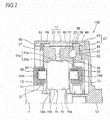
- FIG. 2 is an enlarged sectional view of main parts of the friction-roller-type reduction gear.
- a friction-roller-type reduction gear 100 is configured to decelerate and transmit rotation input from an input shaft 11 to an output shaft 13, the input shaft 11 and the output shaft 13 being concentrically arranged.
- the friction-roller-type reduction gear 100 has a sun roller 15 arranged concentrically with the input shaft 11, a ring roller 17, a plurality of intermediate rollers 19, a coupling part 21 configured to couple the ring roller 17 and the output shaft 13, and a loading cam mechanism 23.
- the friction-roller-type reduction gear 100 has pivot holders 71 each of which is provided for each of the plurality of intermediate rollers 19 and is configured to rotatably support a pair of support shafts (rotational shafts) 19B, 19B of the intermediate roller 19, and a carrier 89 configured to support the pivot holders 71 so that each pivot holder can be pivotally displaceable about an eccentric position from the support shafts 19B, 19B, which is a pivot center.
- the pivot holder 71 has a pair of bearing parts 73 configured to respectively support the support shafts 19B, 19B.
- the bearing parts 73 are inserted into shaft holes formed in the carrier 89 and support the pivot holder 71 with respect to the carrier 89 to be pivotally displaceable.
- the pivot center of the pivot holder 71 is arranged in a region in an outer diameter of the bearing part 73, and the bearing parts 73, 73 are integrally coupled by a bridging part, which will be described later. Thereby, relative distortion of the bearing parts 73, 73 is suppressed.
- the sun roller 15 is a solid roller formed integrally with the input shaft 11 at one end of the input shaft 11 shown in FIG. 2 .
- An outer peripheral surface 15a of the sun roller 15 is formed as a concave curved surface of which an outer edge shape of an axial section is a concave curve of a single arc shape.
- the ring roller 17 has a pair of ring roller elements provided side by side in an axial direction, i.e., a fixed ring roller element 29 and a moveable ring roller element 31 configured to be freely moveable in the axial direction.
- Each of the ring roller elements 29, 31 is arranged concentrically with the sun roller 15 at an outer periphery-side of the sun roller 15 within the cup-shaped coupling part 21.
- Inner peripheral surfaces 29a, 31a of the fixed ring roller element 29 and the moveable ring roller element 31 are configured as annular inclined surfaces of which an outer edge shape of an axial section is linear.
- the inclined surfaces are inclined surfaces of which distances to a center of rotation of the intermediate roller 19 gradually decrease from opposing end surfaces 33, 35 of the ring roller elements 29, 31 to axially opposite outer end surfaces 37, 39.
- the inclined surfaces become rolling-contact surfaces on which the intermediate roller 19 is to roll.
- the inner peripheral surfaces 29a, 31a are not limited to the inclined surfaces and may be concave curved surfaces of which an outer edge shape of an axial section is a concave curve of a single arc shape.
- the plurality of intermediate rollers 19 is arranged in an annular space between the outer peripheral surface 15a of the sun roller 15 and an inner peripheral surface 17a of the ring roller 17.
- An outer peripheral surface 19a of the intermediate roller 19 is a convex curved surface of which an outer edge shape of an axial section is a convex curve of a single arc shape.
- the outer peripheral surface 19a becomes a traction surface configured to rolling-contact the outer peripheral surface 15a of the sun roller 15 and the inner peripheral surface 17a of the ring roller 17.
- the coupling part 21 has a base end portion 41 having a substantially circular plate shape and coupled to the output shaft 13 at a central portion thereof and a cylindrical roller holding part 43 extending axially from an outer peripheral edge of the base end portion 41 and configured to hold the ring roller 17 and the like at an inner diameter-side thereof.
- the base end portion 41 is formed by cutting processing such as lathe machining, for example, and the roller holding part 43 is formed by plastic forming such as press molding. Thereby, shaft centers of the base end portion 41 and the roller holding part 43 are matched with high precision at low cost.
- a preload spring 45 having a corrugated plate shape, a cam ring 49, a ball 51, which is a rolling element, the moveable ring roller element 31, the fixed ring roller element 29 and a snap ring 53 are arranged in corresponding order from the base end portion 41-side in the roller holding part 43.
- An inner peripheral part of the roller holding part 43 is formed with concave grooves 55 along the axial direction.
- the concave grooves 55 are formed at a plurality of circumferential places of the inner peripheral part of the roller holding part 43.
- protrusions 58 formed at a plurality of places of an outer peripheral part of the fixed ring roller element 29 and protruding radially outward are respectively accommodated.
- the cam ring 49 has a plurality of protrusions 59 protruding radially outward from an outer peripheral part thereof.
- the protrusions 59 of the cam ring 49 are respectively engaged with the concave grooves 55 of the roller holding part 43 without any rattling in a rotating direction, like the protrusions 58 of the fixed ring roller element 29. Thereby, rotary torque can be transmitted among the roller holding part 43, the ring roller 17 and the cam ring 49.
- the cam ring 49 has a notched portion 63 obtained by annularly notching a part of an outer diameter-side and formed on an outer end surface facing the output shaft 13.
- the notched portion 63 is mounted with the preload spring 45 configured to axially press the cam ring 49.
- An end portion of the roller holding part 43 opposite to the base end portion 41 is formed with a ring groove 57 (refer to FIG. 1 ) on an inner peripheral surface of the end portion along the circumferential direction.
- the snap ring 53 is fitted in the ring groove 57.
- the snap ring 53 is configured to fix the fixed ring roller element 29 to the roller holding part 43 with regulating an axial position.
- the moveable ring roller element 31, the cam ring 49 and the ball 51 shown in FIG. 2 configure the loading cam mechanism 23.
- the loading cam mechanism 23 is configured to increase or decrease pressing forces of the respective rolling-contact surfaces of the sun roller 15, the ring roller 17 and the intermediate roller 19 in proportional to the transmission torque.
- FIG. 3 is a plan view of the moveable ring roller element 31, depicting cam grooves of the loading cam mechanism 23.
- shapes and arrangement of the cam grooves shown in FIG. 3 apply to the cam ring 49, too.
- the outer end surface 39 of the moveable ring roller element 31 is formed with a plurality of (three, in the shown example) first cam grooves 65 along the circumferential direction.
- An end surface of the cam ring 49 facing the moveable ring roller element 31 is also formed with second cam grooves 67. That is, a plurality of (three, in the shown example) second cam grooves 67 are formed with facing the first cam grooves 65 at circumferential positions of the cam ring 49 corresponding to the first cam grooves 65 of the moveable ring roller element 31.
- Each ball 71 is interposed between the first cam groove 65 and the second cam groove 67.
- An axial groove depth of each of the first cam groove 65 and the second cam groove 67 is deepest at a central portion in the circumferential direction and becomes gradually shallow toward end portions in the circumferential direction of each of the cam grooves 65, 67.
- FIGS. 4A and 4B are sectional views taken along a line IV-V of FIG. 3 , in which FIG. 4A is a sectional view depicting a state where the loading cam mechanism 23 shown in FIG. 2 does not generate an axial thrust force, and FIG. 4B is a sectional view depicting a state where the loading cam mechanism 23 shown in FIG. 2 generates an axial thrust force.
- each ball 51 is disposed at the deepest portions of the respective cam grooves 65, 67, as shown in FIG. 4A .
- the cam ring 49 is pressed toward the moveable ring roller element 31 by an elastic force of the preload spring 45 (refer to FIG. 2 ).
- each ball 51 moves to the shallow portions of the respective cam grooves 65, 67, as shown in FIG. 4B . Thereby, an axial thrust force of pressing the moveable ring roller element 31 toward the fixed ring roller element 29 is generated.
- each rolling-contact part increases, so that each roller is elastically deformed. Also, the intermediate roller 19 is displaced toward the fixed ring roller element 29 in association with the axial displacement of the moveable ring roller element 31.
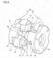
- FIG. 5 is an outward perspective view of the pivot holder 71 configured to support the intermediate roller 19.
- the same or corresponding members as or to the above members are denoted with the same reference numerals and the descriptions thereof are simplified or omitted.
- the intermediate roller 19 has a roller main body 19A having the outer peripheral surface 19a becoming a traction surface, and a pair of support shafts 19B, 19B extending axially outward from both end surfaces 19b, 19b of the roller main body 19A.
- the intermediate roller 19 is a solid member of which the roller main body 19A and the pair of support shafts 19B, 19B are integrally formed.
- the pair of support shafts 19B, 19B is respectively supported to the pivot holder 71.
- the pivot holders 71 are independently provided for each of the plurality of intermediate rollers 19, respectively.
- One intermediate roller 19 is supported to each pivot holder 71.
- the pivot holder 71 is attached to the carrier 89 (refer to FIG. 1 ) so that the support shafts 19B, 19B are parallel with the input shaft 11.
- the pivot holder 71 has a pair of bearing parts 73, 73 configured to respectively support outer diameter parts of the support shafts 19B, 19B.
- An outer peripheral surface of each of the bearing parts 73, 73 has a circular axial section, and a circle center (central axis of rotation) of the axial section becomes a pivot center (pivot axis A XO ) of the pivot holder 71.
- the pair of bearing parts 73, 73 has arm parts 75, 75 extending radially outward from inner sides facing the end surfaces 19b of the intermediate roller 19, respectively.
- the arm parts 75, 75 have connecting posts 77, 77 provided at tip portions opposite to the bearing parts 73, 73, respectively.
- the connecting posts 77, 77 extend in the axial direction perpendicular to the extension direction of the arm parts 75, respectively, and are fastened to each other by a fixing bolt 113 (refer to FIG. 7 ) (which will be described later) with tips being butted to each other.
- the pair of arm parts 75, 75 and the pair of connecting posts 77, 77 configure a bridging part 79 extending from both end surfaces 19b, 19b of the intermediate roller 19 beyond the outer peripheral surface 19a.
- FIG. 6 is an exploded perspective view of the carrier 89 having the intermediate rollers mounted thereto.
- the carrier 89 has a first carrier member 91 and a second carrier member 93.
- the first carrier member 91 and the second carrier member 93 have a disc-shaped bottom part 95 and pillar parts 97 provided at equal intervals at a plurality of places (three places, in the shown example) in the circumferential direction of the bottom part 95, respectively.
- the pillar part 97 of the first carrier member 91 and the pillar part 97 of the second carrier member 93 are formed with insertion holes 99, 101 penetrating therethrough, respectively.
- a bolt (not shown) is inserted into each of the insertion holes 99, 101.
- the bolts inserted into the insertion holes 99, 101 fix the carrier 89 to a motor main body (not shown) with corresponding tip portions of the respective pillar parts 97, 97 being butted to each other.
- the pivot holder 71 configured to support the intermediate roller 19 is arranged between the pillar parts 97 arranged side by side in the circumferential direction.
- FIG. 7 is a partially sectional perspective view, depicting a support structure of the intermediate roller 19 with a part of the pivot holder 71 and the carrier 89 being cut out.
- One bearing part 73 of the pivot holder 71 is rotatably inserted into a holder support part 82 formed in the bottom part 95 (refer to FIG. 6 ) of the first carrier member 91.
- the other bearing part 73 is rotatably inserted into a holder support part 82 formed in the bottom part 95 of the second carrier member 93.
- the holder support parts 82, 82 are blind holes of which one end portion is closed, and are coaxially formed, respectively.
- the bearing part 73 of the pivot holder 71 inserted into the holder support part 82 has substantially the same outer diameter as an inner diameter of the holder support part 82, and is configured to rotate as an outer peripheral surface of the bearing part 73 and an inner peripheral surface of the holder support part 82 slide relative to each other. Thereby, the pivot holder 71 is supported to the carrier 89 so that it can be freely pivotable.
- the pair of support shafts 19B of the intermediate roller 19 is pivotally supported to support holes 80 of the bearing parts 73 via needle bearings 27.
- the needle bearing 27 is a shell-type or solid-type needle bearing having a needle roller 83, a retainer 85 and an outer ring 87.
- the needle bearing 27 is configured to support the intermediate roller 19 to be rotatable and to be feely moveable in the axial direction.
- a ball bearing may be used instead of the needle bearing 27.
- the arm part 75 and the connecting post 77 extending from each of the bearing parts 73, 73 are fastened by a fixing bolt 113 inserted into a fixing hole 111 formed in the connecting post 77.
- a fixing bolt 113 inserted into a fixing hole 111 formed in the connecting post 77.
- the bridging part 79 having the above configuration is configured to integrally couple the pair of bearing parts 73, 73 and to suppress the bearing parts 73, 73 from being relatively distorted.
- the bridging part 79 is formed over the outer peripheral surface 19a at the radially outer side of the outer peripheral surface 19a of the intermediate roller 19, so that it is possible to suppress the torsion generated at the bearing parts 73, 73 with a small force.
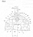
- FIG. 8 is a side view of the carrier 89.
- the bearing part 73 of the pivot holder 71 is inserted into the holder support part 82 of the second carrier member 93, and the intermediate roller 19 is in contact with the sun roller 15.
- a normal line at a contact point P a of the sun roller 15 and the intermediate roller 19, which passes a center O S of the sun roller 15, is denoted as a virtual line L b .
- the virtual line L b is a line perpendicular to a tangential line L a at the contact point P a .
- a center OR of the support shaft 19B is located on the virtual line L b .
- a pivot center O OS which is a center of the shaft hole of the holder support part 82, is located at a position distant from the center O R of the support shaft 19B at the reference state and on a line L C parallel with the tangential line L a .
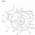
- FIG. 9 pictorially depicts the reference state of the pivot holder 71 and the intermediate roller 19 and a state after the pivoting.
- the pivot holder 71 is configured so that the center O R of the support shaft 19B is located on the line L C and an interaxial distance between the center O R on the line L C and the pivot center O OS is an eccentricity amount r OS by which the pivot holder 71 pivots.
- the center O R of the support shaft 19B is spaced from the line L C and moves to a position denoted with a center O Ra . That is, the center O Ra moves in a direction of the virtual line L b by a distance ⁇ H, so that a position of the outer peripheral surface 19a of the intermediate roller 19 is displaced by the distance ⁇ H. Therefore, the intermediate roller 19 protrudes in a radially outward direction of the carrier 89.
- the intermediate roller 19 is radially displaced by the distance ⁇ H. Also, when the pivot holder 71 changes by an inclination angle of the opposite direction to the shown example, the intermediate roller 19 is displaced in the opposite direction to the shown example. Thereby, the intermediate roller 19 can freely appear in the radial direction of the carrier 89 in correspondence to the transmission torque of the reduction gear.
- a radius r of the bearing part 73 of which a central axis of rotation is the pivot axis A XO is obtained by a following equation (1). r ⁇ r OS + r 0 + t min
- r B a radius of the needle bearing 27 and an inner peripheral surface radius of the support hole 80 (refer to FIG. 7 ) of the bearing part 73 configured to support the support shaft 19B.
- t min a radial minimum thickness of the bearing part 73.
- the radial minimum thickness t min is a minimum thickness of the bearing part 73 necessary to securely hold the bearing under using environments.
- r OS in the equation (1) is preferably set to satisfy a relation of an equation (2).
- the eccentricity amount r OS which is the interaxial distance between the pivot center O OS , which is a center of rotation of the bearing part 73, and the center O R of the rotational shaft, is made shorter than a length, which is to be obtained by subtracting a sum of the inner peripheral surface radius r B of the support hole 80 (refer to FIG. 7 ) of the bearing part 73 configured to support the support shaft 19B and the radial minimum thickness t min of the bearing part 73 from the radius r M of the intermediate roller 19.
- the eccentricity amount r OS which is the interaxial distance between the center O R and the pivot center O OS , is set to be equal to or smaller than the maximum radius R M of the outer diameter of the intermediate roller 19, so that it is possible to implement a more compact layout without any interference between the pivot holder 71 and the respective members.
- the pivot center O OS is located on the line L C .
- the line L C indicates a direction in which the tangential forces F1, F2 shown in FIG. 15 are applied, and is an applying line of the torque reaction force of the transmission torque to be applied to the pivot holder 71.
- the pivot center O OS is located on the line L C , even when the torque reaction force is applied to the pivot holder 71, the rotational moment is not applied to the pivot holder 71. That is, a configuration where the component force of the torque reaction force is not generated is made. Therefore, the intermediate roller 19, the sun roller 15 and the ring roller 17 are not influenced by the component force of the torque reaction force, and inequality of the contact surface pressures of the respective contact points is suppressed.
- the reduction gear can realize stable power transmission characteristics, irrespective of operation conditions such as a torque transmission direction.
- the sun roller 15 shown in FIG. 1 is inserted along the central axis of the carrier 89 from the axial end surface of the carrier 89. Since the outer edge shape of the axial end surface of the sun roller 15 is the concave curved surface, when inserting the sun roller 15, the intermediate rollers 19 mounted to the carrier 89 are temporarily retreated toward the outer diameter-side.
- the pivot holder 71 configured to support the intermediate roller 19 is also pivoted about the pivot axis Axo, as shown in FIG. 8 .
- the pivot holder 71 and the intermediate roller 19 it is necessary to narrow a radial section of the pillar part 97 provided for the carrier 89. In this case, the stiffness of the carrier 89 is lowered and a degree of design freedom in the pillar part 97 is also lowered.
- the pivot center of the pivot holder 71 is located at a position deviating from the tangential line direction of the roller contact point and the component force of the tangential force is applied to the contact point of the roller. For this reason, inequality occurs between a normal force of the sun roller contact point and a normal force of the ring roller contact point.
- This inequality can be solved by the structure where the eccentricity amount r OS , which is the interaxial distance between the pivot axis of the pivot holder 71 and the intermediate roller 19, is set in accordance with the equation (2). That is, the pivot axis is made to face toward the tangential line direction of the roller contact point, so that it is possible to balance the normal forces.
- the bridging part 79 and the pivot center O OS are arranged as shown in FIG. 8 . That is, on the basis of the virtual line L b passing the centers of the intermediate roller 19 and the sun roller 15, one side (a left side in FIG. 8 ) of the virtual line L b is set as a side at which the bridging part 79 of the pivot holder 71 is to be arranged and the other side (a right side in FIG. 8 ) is set as a side at which the pivot center O OS is to be arranged.
- FIGS. 10A and 10B depict a relation between the pillar parts 97 of the first carrier member 91 (also, the second carrier member 93) and the bridging parts 79 of the pivot holders 71, in which FIG. 10A is a sectional view illustrating a state where the intermediate rollers 19 are in contact with the sun roller 15, and FIG. 10B is a sectional view illustrating a state where the pivot holders 71 are pivoted to move the intermediate rollers 19 toward the outer diameter-side of the sun roller 15.
- the intermediate rollers 19 are temporarily retreated toward the outer diameter-side from the state of FIG. 10A to the state of FIG. 10B .
- the bridging part 79 is rotated toward the outer diameter-side about the pivot center O OS by an angle ⁇ OUT , so that the intermediate roller 19 is moved toward the outer diameter-side.
- the bridging part 79 is moved toward the outer diameter-side, so that the interference between the bridging part 79 and the pillar part 97 of the carrier 89 is reduced and the radial section of the pillar part 97 is enlarged.
- the pillar part 97 is formed with an oil passage (which will be described later) and the insertion holes 99, 101 for attachment (refer to FIG. 6 ), so that lubricant oil is supplied from the carrier 89 to each roller and bearing through the oil passage.
- the greater the radial section of the pillar part 97 is, a degree of design freedom increases.
- the friction-roller-type reduction gear 100 having the configuration where the loading cam mechanism 23 is provided for only one moveable ring roller element 31 of the pair of ring roller elements 29, 31, the normal force is applied to both the rolling-contact surfaces by the loading cam mechanism 23, in correspondence to the contact angle between the moveable ring roller element 31 and the intermediate roller 19.
- the intermediate rollers 19 are pressed by the sun roller 15 and are moved toward the inner diameter-side by the elastic deformations of the respective parts thereof. Also, as described with reference to FIGS. 10A and 10B , the bridging parts 79 of the pivot holders 71 are moved toward the inner diameter-side.
- a moving amount of the intermediate roller 19 toward the inner diameter-side is a sum of elastic deformation amounts of the intermediate roller 19 and the sun roller 15 and an elastic deformation amount of the rolling-contact surface, and is very small, as compared to the retreat amount toward the outer diameter-side during the assembling process. Since the moving amount of the intermediate roller 19 is small, a moving amount of the bridging part 79 toward the inner diameter-side is also smaller than the moving amount during the assembling process.
- the bridging part 79 is made to move toward the outer diameter-side during the assembling process in which the moving amount of the bridging part 79 is great, so that it is possible to suppress the interference between the pillar part 97 and the bridging part 79 to the minimum. Thereby, it is possible to improve the stiffness of the pillar part 97 and the degree of design freedom.
- pivot holder 71 ref having another structure is described for comparison with the pivot holder 71 having the above configuration.
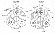
- FIGS. 11A and 11B are reference views depicting a relation between pillar parts 97 ref of the carrier and bridging parts 79 ref of the pivot holders 71 ref , in which FIG. 11A is a sectional view illustrating a state where the intermediate rollers 19 are in contact with the sun roller 15, and FIG. 11B is a sectional view illustrating a state where the pivot holders 71 ref are pivoted to move the intermediate rollers 19 toward the outer diameter-side of the sun roller 15.
- both the bridging part 79 ref of the pivot holder 71 ref and the pivot center O OS are arranged at one side (a left side in FIG. 11A of the virtual line L b .
- the loading cam mechanism 23 is arranged only at the axially outer side of one of the ring roller elements 29, 31.
- the loading cam mechanism 23 is configured to displace the moveable ring roller element 31 toward the fixed ring roller element 29, in correspondence to the rotary torque from the input shaft 11. Thereby, an axial force is applied to the intermediate roller 19.
- the intermediate roller 19 is applied with the axial force and axially slides.
- the sliding operation is implemented by the needle bearing 27 shown in FIG. 7 .
- the needle bearing 27 enables the smooth sliding operation with a low resistance without interfering with the axial displacement of the intermediate roller 19. Thereby, when the intermediate roller 19 is applied with the axial force from the loading cam mechanism 23, the intermediate roller smoothly slides to suppress wear and friction.
- the intermediate roller 19 is supported to the pivot holder 71 so that it can axially move.
- gaps ⁇ are respectively formed between the one and other end surfaces 19b of the roller main body 19A and the holder inner surfaces of the pivot holder 71, i.e., between the end surfaces 19b and the facing inner surfaces of the pair of arm parts 75, 75.
- FIG. 12 is a partially sectional perspective view of the pivot holder 71 and the carrier 89 configured to support the same.
- the carrier 89 is formed therein with an oil passage configured to communicate with the holder support part 82. Through the oil passage, the lubricant oil is supplied to the holder support part 82.
- the bearing part 73 of the pivot holder 71 is formed on its axial outer end surface with an opening hole 117 for exposing the end surface of the support shaft 19B.
- the lubricant oil in the holder support part 82 is supplied to the needle bearing 27 (refer to an arrow P1 in FIG. 12 ).
- the lubricant oil supplied into the opening hole 117 is supplied between the inner peripheral surface of the holder support part 82 and the outer peripheral surface of the bearing part 73 (refer to an arrow P2 in FIG. 12 ), so that the lubricant oil to the pivot axis is secured.
- FIG. 13 is a partially sectional perspective view depicting a configuration of a modified embodiment of the intermediate roller and the pivot holder.
- An intermediate roller 20 has a traction surface on an outer peripheral surface 20a and is formed with a shaft hole 121 penetrating an inner diameter part thereof.
- a shaft-shaped bridging part 123 is inserted into the shaft hole 121 via needle bearings 27A.
- the needle bearing 27A is a cage & roller having the needle roller 83 and the retainer 85. In this configuration, the needle bearings are axially arranged in two rows.
- Bearing parts 73A, 73A are respectively fixed to both end portions of the bridging part 123.
- the bearing parts 73A, 73A have an outer peripheral surface of which an axial section is circular and central axes of rotation thereof become a pivot axis A XO .
- a central axis A XR of the bridging part 123 is arranged at an eccentric position from the pivot axis Axo.
- the bearing parts 73A, 73A are coupled by the bridging part 123, so that the same effects as the pivot holder 71 are achieved. Also, since this configuration is a structure where the bridging part 123 penetrates the inner diameter part of the intermediate roller 20, a space of the outer diameter-side of the intermediate roller 20 is not required. For this reason, the support structure of the intermediate roller 20 having the above configuration can be applied to a reduction gear having a large speed reduction ratio and a small clearance between the intermediate rollers 20, too.
- FIG. 14 is a perspective view depicting a modified embodiment of the carrier having the intermediate rollers mounted thereto.
- the pillar parts 97 which are to be provided for each of the first carrier member 91 and the second carrier member 93 shown in FIG. 6 , are provided only for one carrier member.
- the other carrier member (not shown) has only the bottom part 95.
- the other configurations are the same as the above.
- the pillar part 97A is integrally configured without being split. For this reason, it is possible to easily process the pillar part 97A and to increase the size precision, as compared to the pillar part configured by a combination of the two components.
- the pivot holder 71 has the bearing parts 73, 73 provided at both sides of the roller main body 19A of the intermediate roller 19.
- the central axes of rotation of the bearing parts 73, 73 become the pivot axis A XO eccentric from the central axis A XR of the support shaft 19B.
- the pair of bearing parts 73, 73 is coupled by the bridging part 79 and is thus integrated.
- the pivot axis A XO at the more radially inner side than the outer peripheral surface of the intermediate roller 19, so that it is possible to improve the degree of layout freedom of the pivot axis A XO .
- the support shafts 19B of the intermediate roller 19 and the pivot axis A XO are all arranged in the inner regions of the outer diameters of the bearing parts 73, 73, it is possible to shorten the axial size of the part configured to support each roller, so that it is possible to make the reduction gear further smaller.
- the relative distortion between the bearing parts 73, 73 is suppressed by the bridging part 79, so that it is possible to stably keep a posture of the intermediate roller 19 all the time.
- the intermediate roller 19 is supported to one frame 331 and the other frame 333, which are independent of each other.
- the bearing part 322 is positioned using the snap ring 335.
- this support form increases the number of components, the processing man-hour and the size of the reduction gear.
- the present invention is based on a Japanese Patent Application No. 2015-81888 filed on April 13, 2015 , a Japanese Patent Application No. 2015-135442 filed on July 6, 2015 and a Japanese Patent Application No. 2016-55717 filed on March 18, 2016 , which are herein incorporated by reference.
Landscapes
- Engineering & Computer Science (AREA)
- General Engineering & Computer Science (AREA)
- Mechanical Engineering (AREA)
- Friction Gearing (AREA)
Abstract
Description
- The present invention relates to a friction-roller-type reduction gear.
- Regarding an electric automobile, a hybrid automobile, an electric four-wheel-drive vehicle and the like that have been recently spread, needs for improving efficiency of an electric motor to prolong a mileage per one charging so as to improve the convenience increase. In order to increase the efficiency of the electric motor, it is preferably to use a small-sized electric motor configured to rotate at high speed, to decelerate rotation of a motor output shaft and then to transmit the rotation to driving wheels of a vehicle. In this case, an operation speed of a reduction gear connected to the motor output shaft considerably increases, so that vibrations and noises are likely to occur.
- Therefore, it is considered to use a friction-roller-type reduction gear so as to suppress the vibrations and noises upon the operation. An example of the friction-roller-type reduction gear of the related art is disclosed in Patent Document 1. The friction-roller-type reduction gear has a sun roller, a ring roller arranged concentrically with the sun roller, and a plurality of intermediate rollers rotatably supported between an outer peripheral surface of the sun roller and an inner peripheral surface of the ring roller. The sun roller has a pair of sun roller elements. One sun roller element comes close to or separates from the other sun roller element in response to transmission torque, thereby changing respective surface pressures of the sun roller elements, the intermediate rollers and the ring roller.
- As shown in
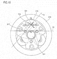
FIG. 15 ,intermediate rollers 315 arranged between asun roller 311 and aring roller 313 are pivotally supported topivot holders 319 configured to pivot aboutpivot axes 317. Thepivot holders 319 pivot about thepivot axes 317, so that roller outer peripheral surfaces of theintermediate rollers 315 can protrude radially outward. - Patent Document 1: Japanese Patent Application Publication No.
2013-104545A - In the above friction-roller-type reduction gear of the related art, a line L0 connecting the
pivot axis 317 of thepivot holder 319 and asupport shaft 321 of theintermediate roller 315 is inclined relative to a tangential line La at a contact point Pa with thesun roller 311. For this reason, when a tangential force F1 or F2 is applied to thesupport shaft 321 of theintermediate roller 315 upon acceleration/deceleration of the reduction gear, component forces of the tangential force are applied to a traction surface of theintermediate roller 315. Thereby, contact surface pressures may be unequal between the contact point Pa with thesun roller 311 and a contact point Pb with thering roller 313. In this case, the durability of the reduction gear may be lowered and a slip may be caused. - Also, since directions of the component forces are changed by a direction of a torque reaction force to be applied to the
pivot holder 319, characteristics of the reduction gear are changed by operation conditions of the reduction gear such as a torque transmission direction. - In order to prevent the above situation, it is necessary to make the line L0 and the tangential line La parallel with each other. However, such arrangement may cause interference between an arm part of the
pivot holder 319 and thering roller 313 depending on a size of each roller, so that a layout of the rollers cannot be made. - Therefore, as shown in
FIG. 16 , it is considered to arrange apivot axis 325 at an eccentric position from aroller rotation axis 323 with respect to a pair of bearingparts 322 configured to support theintermediate roller 315. That is, outer peripheral surfaces of the bearingparts 322 having a circular axial section are rotatably inserted intorespective shaft holes 330 formed inframes parts 322 are set as thepivot axis 325. Also, thebearing part 322 is configured to support thesupport shaft 321 of theintermediate roller 315 at an eccentric position from thepivot axis 325. - According to the above structure, since it is possible to lay out the
pivot axis 325 at aside surface 315a-side of theintermediate roller 315, it is possible to arrange thepivot axis 325 on the tangential line La. - However, according to the structure shown in
FIG. 16 , since the pivoting occurs at each of the bearingparts intermediate roller 315, relative distortion occurs at the bearingparts intermediate roller 315 is inclined occurs and the slip increases in a contact ellipse on the traction surface, so that power transmission efficiency is lowered. In the meantime, herein, the tilt means that the roller is inclined in a plane configured by the sun roller rotation axis and the intermediate roller rotation axis. - The present invention has been made in view of the above situations, and an object of the present invention is to provide a friction-roller-type reduction gear capable of preventing tilt of intermediate rollers without applying a torque component force due to torque transmission of the reduction gear to the intermediate rollers and preventing surface pressures of respective contact points of the intermediate rollers, a sun roller and a ring roller from being unequal.
- The present invention is configured as follows.
- (1) A friction-roller-type reduction gear including:
- a sun roller arranged concentrically with an input shaft;
- a ring roller arranged concentrically with the sun roller at an outer periphery-side of the sun roller and coupled to an output shaft;
- a plurality of intermediate rollers configured to rolling-contact an outer peripheral surface of the sun roller and an inner peripheral surface of the ring roller;
- a plurality of pivot holders each of which is provided for each of the plurality of intermediate rollers and is configured to support a rotational shaft of the intermediate roller;
- a carrier configured to support the plurality of pivot holders, respectively, and
- a loading cam mechanism configured to apply a pressing force, which is proportional to a magnitude of transmission torque to be applied to rolling-contact surfaces between respective rollers of the sun roller, the ring roller and the intermediate rollers, to the rolling-contact surfaces,
- wherein each of the pivot holders has:
- a pair of bearing parts configured to support the rotational shaft of the intermediate roller and having a pivot center at an eccentric position from a center of the rotational shaft, and
- a bridging part configured to integrally couple the bearing parts,
- wherein the carrier has holder support parts configured to rotatably support the bearing parts,
- wherein an interaxial distance between the pivot center of the bearing part and the center of the rotational shaft is equal to or smaller than a maximum radius of an outer diameter of the intermediate roller, and
- wherein the pivot center is located on an applying line of a torque reaction force of transmission torque to be applied to the pivot holder.
According to the friction-roller-type reduction gear, since a torque component force resulting from the torque transmission is not generated, contact surface pressures of respective contact points of the intermediate rollers, the sun roller and the ring roller are not unequal and become stable. Also, it is possible to obtain stable power transmission characteristics, irrespective of operation conditions of the reduction gear such as a torque transmission direction. - (2) The friction-roller-type reduction gear according to the above (1),
wherein the interaxial distance between the center of the pivot axis and the center of the rotational shaft is smaller than a length, which is to be obtained by subtracting a sum of an inner peripheral surface radius of the holder support part configured to support the rotational shaft and a radial minimum thickness of the bearing part from a radius of the intermediate roller.
According to the friction-roller-type reduction gear, it is possible to arrange the bearing parts with high space efficiency without interfering with the sun roller and the ring roller. - (3) The friction-roller-type reduction gear according to the above (1) or (2),
wherein the bridging part is arranged over an outer peripheral surface of the intermediate roller from both end surfaces of the intermediate roller.
According to the friction-roller-type reduction gear, it is possible to suppress distortion, which is be generated at the bearing parts, with small force. - (4) The friction-roller-type reduction gear according to one of the above (1) to (3),
wherein the rotational shaft of the intermediate roller is inserted into a shaft hole axially penetrating an inner diameter part, and
wherein the bearing parts are respectively fixed to both end portions of the rotational shaft, so that the bridging part is configured. - According to the friction-roller-type reduction gear, since a space of the outer diameter-side of the intermediate roller is not required, the friction-roller-type reduction gear can be applied to a reduction gear having a large speed reduction ratio and a small clearance between the intermediate rollers, too.
- According to the present invention, it is possible to prevent the tilt of the intermediate rollers without applying a torque component force due to the torque transmission of the reduction gear to the intermediate rollers and to prevent the surface pressures of respective contact points of the intermediate rollers, the sun roller and the ring roller from being unequal.
-
-
FIG. 1 is a partially sectional perspective view of a friction-roller-type reduction gear, illustrating an embodiment of the present invention. -
FIG. 2 is an enlarged sectional view of main parts of the friction-roller-type reduction gear shown inFIG, 1 . -
FIG. 3 is a plan view of a moveable ring roller element, depicting cam grooves of a loading cam mechanism. -
FIG. 4A is a sectional view taken along a line IV-IV ofFIG. 3 , depicting a state where the loading cam mechanism does not generate an axial thrust force, andFIG. 4B is a sectional view taken along a line IV-IV ofFIG. 3 , depicting a state where the loading cam mechanism generates an axial thrust force. -
FIG. 5 is an outward perspective view of a pivot holder configured to support an intermediate roller. -
FIG. 6 is an exploded perspective view of a carrier having the intermediate rollers mounted thereto. -
FIG. 7 is a partially sectional perspective view, depicting a support structure of the intermediate roller with a part of the pivot holder and the carrier being cut out. -
FIG. 8 is a side view of the carrier. -
FIG. 9 pictorially illustrates a reference state of the pivot holder and the intermediate roller and a state after pivoting. -
FIG. 10A is a sectional view depicting a relation between pillar parts of the carrier and bridgingparts 79 of the pivot holders and illustrating a state where the intermediate rollers are in contact with a sun roller, andFIG. 10B is a sectional view depicting a relation between the pillar parts of the carrier and the bridging parts of the pivot holders and illustrating a state where the pivot holders are pivoted to move the intermediate rollers toward an outer diameter-side of the sun roller. -
FIG. 11A is a reference view depicting a relation between pillar parts of the carrier and bridging parts of pivot holders and is a sectional view illustrating a state where the intermediate rollers are in contact with the sun roller, andFIG. 11B is a reference view depicting a relation between the pillar parts of the carrier and the bridging parts of the pivot holder and is a sectional view illustrating a state where the pivot holders are pivoted to move the intermediate rollers toward the outer diameter-side of the sun roller. -
FIG. 12 is a partially sectional perspective view of the pivot holder and the carrier configured to support the pivot holder. -
FIG. 13 is a partially sectional perspective view depicting a configuration of a modified embodiment of the intermediate roller and the pivot holder. -
FIG. 14 is a perspective view depicting a configuration of a modified embodiment of the carrier having the intermediate rollers mounted thereto. -
FIG. 15 is a configuration view of main parts of a reduction gear, depicting an arrangement relation of a sun roller, a ring roller and intermediate rollers of the related art. -
FIG. 16 illustrates a configuration of the related art in which a pivot axis is provided for outer diameter parts of bearing parts configured to the intermediate roller at an eccentric position from a roller rotation axis. -
FIG. 1 is a partially sectional perspective view of a friction-roller-type reduction gear, illustrating an embodiment of the present invention, andFIG. 2 is an enlarged sectional view of main parts of the friction-roller-type reduction gear. As shown inFIGS. 1 and2 , a friction-roller-type reduction gear 100 is configured to decelerate and transmit rotation input from aninput shaft 11 to anoutput shaft 13, theinput shaft 11 and theoutput shaft 13 being concentrically arranged. The friction-roller-type reduction gear 100 has asun roller 15 arranged concentrically with theinput shaft 11, aring roller 17, a plurality ofintermediate rollers 19, acoupling part 21 configured to couple thering roller 17 and theoutput shaft 13, and aloading cam mechanism 23. - Also, although described in detail later, the friction-roller-
type reduction gear 100 haspivot holders 71 each of which is provided for each of the plurality ofintermediate rollers 19 and is configured to rotatably support a pair of support shafts (rotational shafts) 19B, 19B of theintermediate roller 19, and acarrier 89 configured to support thepivot holders 71 so that each pivot holder can be pivotally displaceable about an eccentric position from thesupport shafts - The
pivot holder 71 has a pair of bearingparts 73 configured to respectively support thesupport shafts parts 73 are inserted into shaft holes formed in thecarrier 89 and support thepivot holder 71 with respect to thecarrier 89 to be pivotally displaceable. In the configuration, the pivot center of thepivot holder 71 is arranged in a region in an outer diameter of the bearingpart 73, and the bearingparts parts - Hereinafter, configurations of the respective parts of the friction-roller-
type reduction gear 100 are sequentially described. - The
sun roller 15 is a solid roller formed integrally with theinput shaft 11 at one end of theinput shaft 11 shown inFIG. 2 . An outerperipheral surface 15a of thesun roller 15 is formed as a concave curved surface of which an outer edge shape of an axial section is a concave curve of a single arc shape. - The
ring roller 17 has a pair of ring roller elements provided side by side in an axial direction, i.e., a fixedring roller element 29 and a moveablering roller element 31 configured to be freely moveable in the axial direction. Each of thering roller elements sun roller 15 at an outer periphery-side of thesun roller 15 within the cup-shapedcoupling part 21. - Inner
peripheral surfaces ring roller element 29 and the moveablering roller element 31 are configured as annular inclined surfaces of which an outer edge shape of an axial section is linear. The inclined surfaces are inclined surfaces of which distances to a center of rotation of theintermediate roller 19 gradually decrease from opposing end surfaces 33, 35 of thering roller elements intermediate roller 19 is to roll. In the meantime, the innerperipheral surfaces - The plurality of
intermediate rollers 19 is arranged in an annular space between the outerperipheral surface 15a of thesun roller 15 and an innerperipheral surface 17a of thering roller 17. - An outer
peripheral surface 19a of theintermediate roller 19 is a convex curved surface of which an outer edge shape of an axial section is a convex curve of a single arc shape. The outerperipheral surface 19a becomes a traction surface configured to rolling-contact the outerperipheral surface 15a of thesun roller 15 and the innerperipheral surface 17a of thering roller 17. - The
coupling part 21 has abase end portion 41 having a substantially circular plate shape and coupled to theoutput shaft 13 at a central portion thereof and a cylindrical roller holding part 43 extending axially from an outer peripheral edge of thebase end portion 41 and configured to hold thering roller 17 and the like at an inner diameter-side thereof. - The
base end portion 41 is formed by cutting processing such as lathe machining, for example, and the roller holding part 43 is formed by plastic forming such as press molding. Thereby, shaft centers of thebase end portion 41 and the roller holding part 43 are matched with high precision at low cost. - As shown in
FIG. 2 , apreload spring 45 having a corrugated plate shape, acam ring 49, aball 51, which is a rolling element, the moveablering roller element 31, the fixedring roller element 29 and asnap ring 53 are arranged in corresponding order from the base end portion 41-side in the roller holding part 43. - An inner peripheral part of the roller holding part 43 is formed with
concave grooves 55 along the axial direction. Theconcave grooves 55 are formed at a plurality of circumferential places of the inner peripheral part of the roller holding part 43. In theconcave grooves 55,protrusions 58 formed at a plurality of places of an outer peripheral part of the fixedring roller element 29 and protruding radially outward are respectively accommodated. - The
cam ring 49 has a plurality ofprotrusions 59 protruding radially outward from an outer peripheral part thereof. Theprotrusions 59 of thecam ring 49 are respectively engaged with theconcave grooves 55 of the roller holding part 43 without any rattling in a rotating direction, like theprotrusions 58 of the fixedring roller element 29. Thereby, rotary torque can be transmitted among the roller holding part 43, thering roller 17 and thecam ring 49. - Also, the
cam ring 49 has a notchedportion 63 obtained by annularly notching a part of an outer diameter-side and formed on an outer end surface facing theoutput shaft 13. The notchedportion 63 is mounted with thepreload spring 45 configured to axially press thecam ring 49. - An end portion of the roller holding part 43 opposite to the
base end portion 41 is formed with a ring groove 57 (refer toFIG. 1 ) on an inner peripheral surface of the end portion along the circumferential direction. In thering groove 57, thesnap ring 53 is fitted. Thesnap ring 53 is configured to fix the fixedring roller element 29 to the roller holding part 43 with regulating an axial position. - Subsequently, the loading cam mechanism is described.
- The moveable
ring roller element 31, thecam ring 49 and theball 51 shown inFIG. 2 configure theloading cam mechanism 23. Theloading cam mechanism 23 is configured to increase or decrease pressing forces of the respective rolling-contact surfaces of thesun roller 15, thering roller 17 and theintermediate roller 19 in proportional to the transmission torque. -
FIG. 3 is a plan view of the moveablering roller element 31, depicting cam grooves of theloading cam mechanism 23. In the meantime, shapes and arrangement of the cam grooves shown inFIG. 3 apply to thecam ring 49, too. - The
outer end surface 39 of the moveablering roller element 31 is formed with a plurality of (three, in the shown example)first cam grooves 65 along the circumferential direction. An end surface of thecam ring 49 facing the moveablering roller element 31 is also formed withsecond cam grooves 67. That is, a plurality of (three, in the shown example)second cam grooves 67 are formed with facing thefirst cam grooves 65 at circumferential positions of thecam ring 49 corresponding to thefirst cam grooves 65 of the moveablering roller element 31. Eachball 71 is interposed between thefirst cam groove 65 and thesecond cam groove 67. - An axial groove depth of each of the
first cam groove 65 and thesecond cam groove 67 is deepest at a central portion in the circumferential direction and becomes gradually shallow toward end portions in the circumferential direction of each of thecam grooves -
FIGS. 4A and 4B are sectional views taken along a line IV-V ofFIG. 3 , in whichFIG. 4A is a sectional view depicting a state where theloading cam mechanism 23 shown inFIG. 2 does not generate an axial thrust force, andFIG. 4B is a sectional view depicting a state where theloading cam mechanism 23 shown inFIG. 2 generates an axial thrust force. At a state where torque is not applied to theinput shaft 11, eachball 51 is disposed at the deepest portions of therespective cam grooves FIG. 4A . At this state, thecam ring 49 is pressed toward the moveablering roller element 31 by an elastic force of the preload spring 45 (refer toFIG. 2 ). - When torque is applied to the
input shaft 11, eachball 51 moves to the shallow portions of therespective cam grooves FIG. 4B . Thereby, an axial thrust force of pressing the moveablering roller element 31 toward the fixedring roller element 29 is generated. - When the
loading cam mechanism 23 generates the axial thrust force, the moveablering roller element 31 shown inFIG. 2 moves toward the fixedring roller element 29, so that an interval between the fixedring roller element 29 and the moveablering roller element 31 decreases. Then, contact positions between the inclined surfaces of the innerperipheral surfaces ring roller 17 and the outerperipheral surface 19a of the convex curved surface of theintermediate roller 19 are changed to conform to elastic deformations of thering roller 17, theintermediate roller 19 and thesun roller 15, so that surface pressures of the rolling-contact parts of thering roller 17, theintermediate roller 19 and thesun roller 15 increase, respectively. As a result, as the transmission torque between theinput shaft 11 and theoutput shaft 13 increases, the surface pressures of the rolling-contact parts between theinput shaft 11 and theoutput shaft 13 increase. - As described above, when the
loading cam mechanism 23 generates the axial thrust force, the surface pressure of each rolling-contact part increases, so that each roller is elastically deformed. Also, theintermediate roller 19 is displaced toward the fixedring roller element 29 in association with the axial displacement of the moveablering roller element 31. - Subsequently, a support form of the
intermediate roller 19 is described.FIG. 5 is an outward perspective view of thepivot holder 71 configured to support theintermediate roller 19. In below descriptions, the same or corresponding members as or to the above members are denoted with the same reference numerals and the descriptions thereof are simplified or omitted. - The
intermediate roller 19 has a rollermain body 19A having the outerperipheral surface 19a becoming a traction surface, and a pair ofsupport shafts end surfaces main body 19A. Theintermediate roller 19 is a solid member of which the rollermain body 19A and the pair ofsupport shafts - The pair of
support shafts pivot holder 71. Thepivot holders 71 are independently provided for each of the plurality ofintermediate rollers 19, respectively. Oneintermediate roller 19 is supported to eachpivot holder 71. Also, thepivot holder 71 is attached to the carrier 89 (refer toFIG. 1 ) so that thesupport shafts input shaft 11. - The
pivot holder 71 has a pair of bearingparts support shafts parts pivot holder 71. - The pair of bearing
parts arm parts intermediate roller 19, respectively. Thearm parts posts parts arm parts 75, respectively, and are fastened to each other by a fixing bolt 113 (refer toFIG. 7 ) (which will be described later) with tips being butted to each other. - The pair of
arm parts posts part 79 extending from bothend surfaces intermediate roller 19 beyond the outerperipheral surface 19a. -
FIG. 6 is an exploded perspective view of thecarrier 89 having the intermediate rollers mounted thereto. Thecarrier 89 has afirst carrier member 91 and asecond carrier member 93. Thefirst carrier member 91 and thesecond carrier member 93 have a disc-shapedbottom part 95 andpillar parts 97 provided at equal intervals at a plurality of places (three places, in the shown example) in the circumferential direction of thebottom part 95, respectively. - The
pillar part 97 of thefirst carrier member 91 and thepillar part 97 of thesecond carrier member 93 are formed withinsertion holes carrier 89 to a motor main body (not shown) with corresponding tip portions of therespective pillar parts - The
pivot holder 71 configured to support theintermediate roller 19 is arranged between thepillar parts 97 arranged side by side in the circumferential direction. -
FIG. 7 is a partially sectional perspective view, depicting a support structure of theintermediate roller 19 with a part of thepivot holder 71 and thecarrier 89 being cut out. One bearingpart 73 of thepivot holder 71 is rotatably inserted into aholder support part 82 formed in the bottom part 95 (refer toFIG. 6 ) of thefirst carrier member 91. The other bearingpart 73 is rotatably inserted into aholder support part 82 formed in thebottom part 95 of thesecond carrier member 93. - The
holder support parts - The bearing
part 73 of thepivot holder 71 inserted into theholder support part 82 has substantially the same outer diameter as an inner diameter of theholder support part 82, and is configured to rotate as an outer peripheral surface of the bearingpart 73 and an inner peripheral surface of theholder support part 82 slide relative to each other. Thereby, thepivot holder 71 is supported to thecarrier 89 so that it can be freely pivotable. - The pair of
support shafts 19B of theintermediate roller 19 is pivotally supported to supportholes 80 of the bearingparts 73 vianeedle bearings 27. Theneedle bearing 27 is a shell-type or solid-type needle bearing having aneedle roller 83, aretainer 85 and anouter ring 87. Theneedle bearing 27 is configured to support theintermediate roller 19 to be rotatable and to be feely moveable in the axial direction. In the meantime, a ball bearing may be used instead of theneedle bearing 27. - The
arm part 75 and the connectingpost 77 extending from each of the bearingparts bolt 113 inserted into a fixinghole 111 formed in the connectingpost 77. Thereby, the pair of bearingparts arm parts posts bolt 113. - The bridging
part 79 having the above configuration is configured to integrally couple the pair of bearingparts parts part 79 is formed over the outerperipheral surface 19a at the radially outer side of the outerperipheral surface 19a of theintermediate roller 19, so that it is possible to suppress the torsion generated at the bearingparts -
FIG. 8 is a side view of thecarrier 89. In the shown example, the bearingpart 73 of thepivot holder 71 is inserted into theholder support part 82 of thesecond carrier member 93, and theintermediate roller 19 is in contact with thesun roller 15. - Herein, a normal line at a contact point Pa of the
sun roller 15 and theintermediate roller 19, which passes a center OS of thesun roller 15, is denoted as a virtual line Lb. The virtual line Lb is a line perpendicular to a tangential line La at the contact point Pa. - At a reference state before the
pivot holder 71 is pivoted, a center OR of thesupport shaft 19B is located on the virtual line Lb. A pivot center OOS, which is a center of the shaft hole of theholder support part 82, is located at a position distant from the center OR of thesupport shaft 19B at the reference state and on a line LC parallel with the tangential line La. -
FIG. 9 pictorially depicts the reference state of thepivot holder 71 and theintermediate roller 19 and a state after the pivoting. At the reference state shown with the dotted line, thepivot holder 71 is configured so that the center OR of thesupport shaft 19B is located on the line LC and an interaxial distance between the center OR on the line LC and the pivot center OOS is an eccentricity amount rOS by which thepivot holder 71 pivots. - When the
pivot holder 71 rotates (pivots) about the pivot center OOS by an angle φ, the center OR of thesupport shaft 19B is spaced from the line LC and moves to a position denoted with a center ORa. That is, the center ORa moves in a direction of the virtual line Lb by a distance ΔH, so that a position of the outerperipheral surface 19a of theintermediate roller 19 is displaced by the distance ΔH. Therefore, theintermediate roller 19 protrudes in a radially outward direction of thecarrier 89. - As described above, when the bearing
parts 73 of thepivot holder 71 slide in theholder support parts 82 of thecarrier 89 shown inFIGS. 7 and8 and thepivot holder 71 is inclined by the angle φ, theintermediate roller 19 is radially displaced by the distance ΔH. Also, when thepivot holder 71 changes by an inclination angle of the opposite direction to the shown example, theintermediate roller 19 is displaced in the opposite direction to the shown example. Thereby, theintermediate roller 19 can freely appear in the radial direction of thecarrier 89 in correspondence to the transmission torque of the reduction gear. - A radius r of the bearing
part 73 of which a central axis of rotation is the pivot axis AXO is obtained by a following equation (1).
- Herein,
- rOS: an eccentricity amount. In
FIG. 8 , on the basis of the virtual line Lb, an eccentricity amount of an opposite side (a right side inFIG. 8 ) to the bridging part 79-side is referred to as a positive eccentricity amount, and an eccentricity amount of a side (a left side inFIG. 8 ) at which the bridgingpart 79 exists is referred to as a negative eccentricity amount. - rB: a radius of the
needle bearing 27 and an inner peripheral surface radius of the support hole 80 (refer toFIG. 7 ) of the bearingpart 73 configured to support thesupport shaft 19B. - tmin: a radial minimum thickness of the bearing
part 73. - In the meantime, the radial minimum thickness tmin is a minimum thickness of the bearing
part 73 necessary to securely hold the bearing under using environments. - When an outer diameter (2r) of the bearing
part 73 is greater than an outer diameter (2rM) of theintermediate roller 19, it is necessary to axially enlarge thepivot holder 71 so as to avoid interference with the sun roller and the ring roller. For this reason, the outer diameter (2r) of the bearingpart 73 is preferably smaller than the outer diameter (2rM) of theintermediate roller 19. Therefore, rOS in the equation (1) is preferably set to satisfy a relation of an equation (2).
- That is, the eccentricity amount rOS, which is the interaxial distance between the pivot center OOS, which is a center of rotation of the bearing
part 73, and the center OR of the rotational shaft, is made shorter than a length, which is to be obtained by subtracting a sum of the inner peripheral surface radius rB of the support hole 80 (refer toFIG. 7 ) of the bearingpart 73 configured to support thesupport shaft 19B and the radial minimum thickness tmin of the bearingpart 73 from the radius rM of theintermediate roller 19. Thereby, it is possible to make an arrangement in which the bearingpart 73 does not interfere with the sun roller and the ring roller and space efficiency is improved. - That is, the eccentricity amount rOS, which is the interaxial distance between the center OR and the pivot center OOS, is set to be equal to or smaller than the maximum radius RM of the outer diameter of the
intermediate roller 19, so that it is possible to implement a more compact layout without any interference between thepivot holder 71 and the respective members. - Also, the pivot center OOS is located on the line LC. The line LC indicates a direction in which the tangential forces F1, F2 shown in
FIG. 15 are applied, and is an applying line of the torque reaction force of the transmission torque to be applied to thepivot holder 71. In this configuration, since the pivot center OOS is located on the line LC, even when the torque reaction force is applied to thepivot holder 71, the rotational moment is not applied to thepivot holder 71. That is, a configuration where the component force of the torque reaction force is not generated is made. Therefore, theintermediate roller 19, thesun roller 15 and thering roller 17 are not influenced by the component force of the torque reaction force, and inequality of the contact surface pressures of the respective contact points is suppressed. Also, the reduction gear can realize stable power transmission characteristics, irrespective of operation conditions such as a torque transmission direction. - In an assembling process of the friction-roller-
type reduction gear 100, thesun roller 15 shown inFIG. 1 is inserted along the central axis of thecarrier 89 from the axial end surface of thecarrier 89. Since the outer edge shape of the axial end surface of thesun roller 15 is the concave curved surface, when inserting thesun roller 15, theintermediate rollers 19 mounted to thecarrier 89 are temporarily retreated toward the outer diameter-side. - When the
intermediate roller 19 is retreated, thepivot holder 71 configured to support theintermediate roller 19 is also pivoted about the pivot axis Axo, as shown inFIG. 8 . For this reason, in order to prevent thepivoting pivot holder 71 and theintermediate roller 19 from interfering with thecarrier 89, it is necessary to narrow a radial section of thepillar part 97 provided for thecarrier 89. In this case, the stiffness of thecarrier 89 is lowered and a degree of design freedom in thepillar part 97 is also lowered. - Also, the pivot center of the
pivot holder 71 is located at a position deviating from the tangential line direction of the roller contact point and the component force of the tangential force is applied to the contact point of the roller. For this reason, inequality occurs between a normal force of the sun roller contact point and a normal force of the ring roller contact point. This inequality can be solved by the structure where the eccentricity amount rOS, which is the interaxial distance between the pivot axis of thepivot holder 71 and theintermediate roller 19, is set in accordance with the equation (2). That is, the pivot axis is made to face toward the tangential line direction of the roller contact point, so that it is possible to balance the normal forces. - However, when the eccentricity amount rOS is small, a pivoting angle, which is necessary to retreat the
intermediate roller 19 during the assembling process of the friction-roller-type reduction gear 100, increases and the radial section of thepillar part 97 decreases. - Therefore, in the friction-roller-
type reduction gear 100 of this configuration, the bridgingpart 79 and the pivot center OOS are arranged as shown inFIG. 8 . That is, on the basis of the virtual line Lb passing the centers of theintermediate roller 19 and thesun roller 15, one side (a left side inFIG. 8 ) of the virtual line Lb is set as a side at which the bridgingpart 79 of thepivot holder 71 is to be arranged and the other side (a right side inFIG. 8 ) is set as a side at which the pivot center OOS is to be arranged. -
FIGS. 10A and 10B depict a relation between thepillar parts 97 of the first carrier member 91 (also, the second carrier member 93) and the bridgingparts 79 of thepivot holders 71, in whichFIG. 10A is a sectional view illustrating a state where theintermediate rollers 19 are in contact with thesun roller 15, andFIG. 10B is a sectional view illustrating a state where thepivot holders 71 are pivoted to move theintermediate rollers 19 toward the outer diameter-side of thesun roller 15. - During the assembling process of the friction-roller-
type reduction gear 100, when inserting thesun roller 15 into thecarrier 89, theintermediate rollers 19 are temporarily retreated toward the outer diameter-side from the state ofFIG. 10A to the state ofFIG. 10B . At this time, the bridgingpart 79 is rotated toward the outer diameter-side about the pivot center OOS by an angle φOUT, so that theintermediate roller 19 is moved toward the outer diameter-side. - In this way, the bridging
part 79 is moved toward the outer diameter-side, so that the interference between the bridgingpart 79 and thepillar part 97 of thecarrier 89 is reduced and the radial section of thepillar part 97 is enlarged. As a result, it is possible to improve the stiffness of thecarrier 89. Also, thepillar part 97 is formed with an oil passage (which will be described later) and the insertion holes 99, 101 for attachment (refer toFIG. 6 ), so that lubricant oil is supplied from thecarrier 89 to each roller and bearing through the oil passage. When forming the oil passage, the greater the radial section of thepillar part 97 is, a degree of design freedom increases. Also, when forming a plurality of oil passages, it is possible to widen an interval between the oil passages, so that workability is improved. - Subsequently, operations of the
pivot holder 71 during the rotation are described. - As shown in
FIGS. 1 and2 , according to the friction-roller-type reduction gear 100 having the configuration where theloading cam mechanism 23 is provided for only one moveablering roller element 31 of the pair ofring roller elements loading cam mechanism 23, in correspondence to the contact angle between the moveablering roller element 31 and theintermediate roller 19. - By the obtained normal force, the
intermediate rollers 19 are pressed by thesun roller 15 and are moved toward the inner diameter-side by the elastic deformations of the respective parts thereof. Also, as described with reference toFIGS. 10A and 10B , the bridgingparts 79 of thepivot holders 71 are moved toward the inner diameter-side. - That is, according to the friction-roller-
type reduction gear 100 having the above configuration, when theloading cam mechanism 23 operates, the bridgingparts 79 are moved toward the inner diameter-side. A moving amount of theintermediate roller 19 toward the inner diameter-side is a sum of elastic deformation amounts of theintermediate roller 19 and thesun roller 15 and an elastic deformation amount of the rolling-contact surface, and is very small, as compared to the retreat amount toward the outer diameter-side during the assembling process. Since the moving amount of theintermediate roller 19 is small, a moving amount of the bridgingpart 79 toward the inner diameter-side is also smaller than the moving amount during the assembling process. - Therefore, the bridging
part 79 is made to move toward the outer diameter-side during the assembling process in which the moving amount of the bridgingpart 79 is great, so that it is possible to suppress the interference between thepillar part 97 and the bridgingpart 79 to the minimum. Thereby, it is possible to improve the stiffness of thepillar part 97 and the degree of design freedom. - Herein, a
pivot holder 71ref having another structure is described for comparison with thepivot holder 71 having the above configuration. -
FIGS. 11A and 11B are reference views depicting a relation betweenpillar parts 97ref of the carrier and bridgingparts 79ref of thepivot holders 71ref, in whichFIG. 11A is a sectional view illustrating a state where theintermediate rollers 19 are in contact with thesun roller 15, andFIG. 11B is a sectional view illustrating a state where thepivot holders 71ref are pivoted to move theintermediate rollers 19 toward the outer diameter-side of thesun roller 15. - As shown in
FIG. 11A , according to the configuration for comparison, on the basis of the virtual line Lb passing the centers of theintermediate roller 19 and thesun roller 15, both the bridgingpart 79ref of thepivot holder 71ref and the pivot center OOS are arranged at one side (a left side inFIG. 11A of the virtual line Lb. - In this case, as shown in
FIG. 11B , during the assembling process, in order to retreat theintermediate roller 19 toward the outer diameter-side, the bridgingpart 79ref of thepivot holder 71ref is largely moved toward the inner diameter-side. When the bridgingpart 79ref is largely moved toward the inner diameter-side, it is necessary to narrow the axial section of thepillar part 97ref so as to prevent the interference between thepillar part 97ref and the bridgingpart 79ref. As a result, the stiffness of the carrier and the degree of design freedom in thepillar part 97ref are lowered. - Subsequently, the axial displacement of the
intermediate roller 19 is described. - As shown in
FIGS. 1 and2 , according to the friction-roller-type reduction gear 100 having the above configuration, theloading cam mechanism 23 is arranged only at the axially outer side of one of thering roller elements loading cam mechanism 23 is configured to displace the moveablering roller element 31 toward the fixedring roller element 29, in correspondence to the rotary torque from theinput shaft 11. Thereby, an axial force is applied to theintermediate roller 19. - The
intermediate roller 19 is applied with the axial force and axially slides. The sliding operation is implemented by theneedle bearing 27 shown inFIG. 7 . Theneedle bearing 27 enables the smooth sliding operation with a low resistance without interfering with the axial displacement of theintermediate roller 19. Thereby, when theintermediate roller 19 is applied with the axial force from theloading cam mechanism 23, the intermediate roller smoothly slides to suppress wear and friction. - In the meantime, the
intermediate roller 19 is supported to thepivot holder 71 so that it can axially move. Between the one and other end surfaces 19b of the rollermain body 19A and the holder inner surfaces of thepivot holder 71, i.e., between the end surfaces 19b and the facing inner surfaces of the pair ofarm parts FIG. 2 ) are respectively formed. By the gaps 8, theintermediate roller 19 can axially move. - Subsequently, an oil supply passage for supplying the lubricant oil to the support bearing of the
intermediate roller 19 is described. -
FIG. 12 is a partially sectional perspective view of thepivot holder 71 and thecarrier 89 configured to support the same. Although not shown, thecarrier 89 is formed therein with an oil passage configured to communicate with theholder support part 82. Through the oil passage, the lubricant oil is supplied to theholder support part 82. - The bearing
part 73 of thepivot holder 71 is formed on its axial outer end surface with anopening hole 117 for exposing the end surface of thesupport shaft 19B. Through theopening hole 117, the lubricant oil in theholder support part 82 is supplied to the needle bearing 27 (refer to an arrow P1 inFIG. 12 ). Also, the lubricant oil supplied into theopening hole 117 is supplied between the inner peripheral surface of theholder support part 82 and the outer peripheral surface of the bearing part 73 (refer to an arrow P2 inFIG. 12 ), so that the lubricant oil to the pivot axis is secured. - In the below, a modified embodiment of the intermediate roller and the pivot holder is described.
FIG. 13 is a partially sectional perspective view depicting a configuration of a modified embodiment of the intermediate roller and the pivot holder. - An
intermediate roller 20 has a traction surface on an outerperipheral surface 20a and is formed with ashaft hole 121 penetrating an inner diameter part thereof. A shaft-shapedbridging part 123 is inserted into theshaft hole 121 vianeedle bearings 27A. Theneedle bearing 27A is a cage & roller having theneedle roller 83 and theretainer 85. In this configuration, the needle bearings are axially arranged in two rows. -
Bearing parts part 123. The bearingparts part 123 is arranged at an eccentric position from the pivot axis Axo. - According to the above configuration, the bearing
parts part 123, so that the same effects as thepivot holder 71 are achieved. Also, since this configuration is a structure where the bridgingpart 123 penetrates the inner diameter part of theintermediate roller 20, a space of the outer diameter-side of theintermediate roller 20 is not required. For this reason, the support structure of theintermediate roller 20 having the above configuration can be applied to a reduction gear having a large speed reduction ratio and a small clearance between theintermediate rollers 20, too. - <Modified Embodiment of Carrier>
-
FIG. 14 is a perspective view depicting a modified embodiment of the carrier having the intermediate rollers mounted thereto. According to acarrier 89A of the modified embodiment, thepillar parts 97, which are to be provided for each of thefirst carrier member 91 and thesecond carrier member 93 shown inFIG. 6 , are provided only for one carrier member. Also, the other carrier member (not shown) has only thebottom part 95. The other configurations are the same as the above. - According to the
carrier 89A having the above configuration, thepillar part 97A is integrally configured without being split. For this reason, it is possible to easily process thepillar part 97A and to increase the size precision, as compared to the pillar part configured by a combination of the two components. - According to the friction-roller-
type reduction gear 100 as described above, it is possible to achieve following effects by the support structure of theintermediate roller 19. - As shown in
FIG. 5 , thepivot holder 71 has the bearingparts main body 19A of theintermediate roller 19. The central axes of rotation of the bearingparts support shaft 19B. Also, the pair of bearingparts part 79 and is thus integrated. - By the above configuration, it is possible to arrange the pivot axis AXO at the more radially inner side than the outer peripheral surface of the
intermediate roller 19, so that it is possible to improve the degree of layout freedom of the pivot axis AXO. Also, since thesupport shafts 19B of theintermediate roller 19 and the pivot axis AXO are all arranged in the inner regions of the outer diameters of the bearingparts parts part 79, so that it is possible to stably keep a posture of theintermediate roller 19 all the time. - Therefore, according to the above configuration, it is possible to improve the degree of design freedom of the carrier and the degree of freedom of arrangement layout of the diverse rollers. Also, as compared to the pivot holder of the related art shown in
FIG. 15 , since the distance between the central axis AXR of thesupport shaft 19B and the pivot axis AXO is shorter, the elastic deformation amount of thearm parts 75 of thepivot holder 71 upon the reduction gear operation is reduced, so that a behavior of the roller is easily stabilized. - Also, according to the pivot holder of the related art shown in
FIG. 16 , theintermediate roller 19 is supported to oneframe 331 and theother frame 333, which are independent of each other. In this case, it is necessary to keep the axial positions of the bearingparts 322 at fixed positions of therespective frames part 322 is positioned using thesnap ring 335. However, this support form increases the number of components, the processing man-hour and the size of the reduction gear. - On the other hand, according to the above configuration, since the pair of bearing
parts part 79, it is not necessary to axially position therespective bearing parts carrier 89. For this reason, it is possible to make a simpler structure. - The present invention is not limited to the above embodiment, and combinations of the respective configurations of the embodiment and changes and modifications, which can be made on the basis of the specification and the well-known technology by one skilled in the art, are also expected by the present invention and are included within the protection scope.
- The present invention is based on a Japanese Patent Application No.
2015-81888 filed on April 13, 2015 2015-135442 filed on July 6, 2015 2016-55717 filed on March 18, 2016 - 11: input shaft, 13: output shaft, 15: sun roller, 15a: outer peripheral surface, 17: ring roller, 17a: inner peripheral surface, 19, 20: intermediate roller, 19a, 20a: outer peripheral surface, 19A: roller main body, 19B: support shaft (rotational shaft), 23: loading cam mechanism, 27: needle bearing, 71: pivot holder, 73: bearing part, 79: bridging part, 82: holder support part, 89: carrier, 100: friction-roller-type reduction gear
Claims (4)
- A friction-roller-type reduction gear comprising:a sun roller arranged concentrically with an input shaft;a ring roller arranged concentrically with the sun roller at an outer periphery-side of the sun roller and coupled to an output shaft;a plurality of intermediate rollers configured to rolling-contact an outer peripheral surface of the sun roller and an inner peripheral surface of the ring roller;a plurality of pivot holders each of which is provided for each of the plurality of intermediate rollers and is configured to support a rotational shaft of the intermediate roller;a carrier configured to support the plurality of pivot holders, respectively, anda loading cam mechanism configured to apply a pressing force, which is proportional to a magnitude of transmission torque to be applied to rolling-contact surfaces between respective rollers of the sun roller, the ring roller and the intermediate rollers, to the rolling-contact surfaces,wherein each of the pivot holders comprises:a pair of bearing parts configured to support the rotational shaft of the intermediate roller and having a pivot center at an eccentric position from a center of the rotational shaft, anda bridging part configured to integrally couple the bearing parts,wherein the carrier has holder support parts configured to rotatably support the bearing parts,wherein an interaxial distance between the pivot center of the bearing part and the center of the rotational shaft is equal to or smaller than a maximum radius of an outer diameter of the intermediate roller, andwherein the pivot center is located on an applying line of a torque reaction force of transmission torque to be applied to the pivot holder.
- The friction-roller-type reduction gear according to claim 1,
wherein the interaxial distance between the center of the pivot axis and the center of the rotational shaft is smaller than a length, which is to be obtained by subtracting a sum of an inner peripheral surface radius of the holder support part configured to support the rotational shaft and a radial minimum thickness of the bearing part from a radius of the intermediate roller. - The friction-roller-type reduction gear according to claim 1 or 2,
wherein the bridging part is arranged over an outer peripheral surface of the intermediate roller from both end surfaces of the intermediate roller. - The friction-roller-type reduction gear according to any one of claims 1 to 3,
wherein the rotational shaft of the intermediate roller is inserted into a shaft hole axially penetrating an inner diameter part, and
wherein the bearing parts are respectively fixed to both end portions of the rotational shaft, so that the bridging part is configured.
Applications Claiming Priority (4)
| Application Number | Priority Date | Filing Date | Title |
|---|---|---|---|
| JP2015081888 | 2015-04-13 | ||
| JP2015135442 | 2015-07-06 | ||
| JP2016055717 | 2016-03-18 | ||
| PCT/JP2016/061842 WO2016167261A1 (en) | 2015-04-13 | 2016-04-12 | Friction-roller-type reduction gear |
Publications (3)
| Publication Number | Publication Date |
|---|---|
| EP3239560A1 true EP3239560A1 (en) | 2017-11-01 |
| EP3239560A4 EP3239560A4 (en) | 2018-05-09 |
| EP3239560B1 EP3239560B1 (en) | 2021-03-10 |
Family
ID=57126781
Family Applications (1)
| Application Number | Title | Priority Date | Filing Date |
|---|---|---|---|
| EP16780052.3A Not-in-force EP3239560B1 (en) | 2015-04-13 | 2016-04-12 | Friction-roller-type reduction gear |
Country Status (4)
| Country | Link |
|---|---|
| US (1) | US10161489B2 (en) |
| EP (1) | EP3239560B1 (en) |
| JP (1) | JP6669166B2 (en) |
| WO (1) | WO2016167261A1 (en) |
Families Citing this family (6)
| Publication number | Priority date | Publication date | Assignee | Title |
|---|---|---|---|---|
| WO2019195229A1 (en) * | 2018-04-02 | 2019-10-10 | Dana Limited | Traction device |
| US11867262B2 (en) * | 2019-03-20 | 2024-01-09 | Nsk, Ltd. | Frictional roller reducer |
| JP7528741B2 (en) * | 2020-11-19 | 2024-08-06 | 日本精工株式会社 | Planetary Roller Traction Drive Device |
| WO2023037412A1 (en) * | 2021-09-07 | 2023-03-16 | 株式会社ユニバンス | Transmission |
| JP2023066534A (en) * | 2021-10-29 | 2023-05-16 | 日本精工株式会社 | Friction roller speed reducer and its manufacturing method |
| PL450126A1 (en) * | 2024-10-24 | 2026-04-27 | Multiprojekt Automatyka Spółka Z Ograniczoną Odpowiedzialnością | Eccentric friction gear |
Family Cites Families (10)
| Publication number | Priority date | Publication date | Assignee | Title |
|---|---|---|---|---|
| US1368570A (en) * | 1919-10-15 | 1921-02-15 | Philippeau Henry | Speed multiplying and reducing gear |
| US3364761A (en) * | 1963-07-19 | 1968-01-23 | Trw Inc | Torque sensitive multi-roller friction drive |
| AT241217B (en) | 1963-10-31 | 1965-07-12 | Simmering Graz Pauker Ag | Planetary gear with four planet gears |
| US3487705A (en) * | 1968-01-15 | 1970-01-06 | Crane Co H W | Friction drive mechanism |
| US5720689A (en) * | 1995-03-03 | 1998-02-24 | Nsk Ltd. | Trunnion arrangement for a toroidal type continuously variable transmission |
| DK171047B1 (en) | 1995-03-29 | 1996-04-29 | Anders Peter Kolstrup | Planetary gears for high rpm |
| US6132330A (en) * | 1997-11-12 | 2000-10-17 | Leggett; Aaron D. | Infinitely variable transmission |
| US7166052B2 (en) * | 2003-08-11 | 2007-01-23 | Fallbrook Technologies Inc. | Continuously variable planetary gear set |
| JP5899850B2 (en) * | 2011-11-17 | 2016-04-06 | 日本精工株式会社 | Friction roller reducer |
| JP6119372B2 (en) * | 2013-03-28 | 2017-04-26 | 日本精工株式会社 | Loading cam device and friction roller reducer |
-
2016
- 2016-04-12 US US15/527,894 patent/US10161489B2/en active Active
- 2016-04-12 WO PCT/JP2016/061842 patent/WO2016167261A1/en not_active Ceased
- 2016-04-12 EP EP16780052.3A patent/EP3239560B1/en not_active Not-in-force
- 2016-04-12 JP JP2017512545A patent/JP6669166B2/en active Active
Also Published As
| Publication number | Publication date |
|---|---|
| EP3239560B1 (en) | 2021-03-10 |
| US10161489B2 (en) | 2018-12-25 |
| JP6669166B2 (en) | 2020-03-18 |
| WO2016167261A1 (en) | 2016-10-20 |
| EP3239560A4 (en) | 2018-05-09 |
| US20180172118A1 (en) | 2018-06-21 |
| JPWO2016167261A1 (en) | 2018-02-08 |
Similar Documents
| Publication | Publication Date | Title |
|---|---|---|
| EP3239560B1 (en) | Friction-roller-type reduction gear | |
| CN103459891B (en) | Friction roller reducer and drive unit for electric vehicles | |
| CN101862972A (en) | Rotational resistance imparting device for spindle drives for machine tools | |
| US8303462B2 (en) | Friction-ring transmission having a friction ring, and method for producing a friction cone | |
| CN118974431A (en) | Reverse input cut-off clutch | |
| WO2016093335A1 (en) | Friction roller speed increaser | |
| EP3279509B1 (en) | Friction roller type reduction gear | |
| JP4948968B2 (en) | Planetary roller type transmission | |
| JP6485180B2 (en) | Friction roller reducer | |
| EP3147541B1 (en) | Friction roller-type transmission | |
| JP6701901B2 (en) | Friction roller reducer | |
| JP2016048112A (en) | Friction roller type reduction gear | |
| EP2811204B1 (en) | Toroidal-type continuously variable transmission | |
| EP3101299A1 (en) | Divided holding device and joint for power-generating apparatus | |
| JP5007600B2 (en) | Toroidal continuously variable transmission | |
| WO2023276770A1 (en) | Planetary roller screw type linear motion mechanism and electric brake device | |
| JP2017180506A (en) | Planetary roller screw type linear motion mechanism and electric brake device | |
| CN103732948B (en) | Power roller unit, its manufacture method and semi-circular buncher | |
| JPH03234403A (en) | Method and device for changing pre-load | |
| JP4106868B2 (en) | Toroidal continuously variable transmission and trunnion drilling method | |
| JP2016114175A (en) | Friction roller type speed reducer | |
| JP6561554B2 (en) | Toroidal continuously variable transmission | |
| JPWO2018174099A1 (en) | Pressing device for toroidal continuously variable transmission | |
| JP2018009665A (en) | transmission | |
| JP2013100842A (en) | Toroidal type continuously variable transmission and machining method for component thereof |
Legal Events
| Date | Code | Title | Description |
|---|---|---|---|
| STAA | Information on the status of an ep patent application or granted ep patent |
Free format text: STATUS: THE INTERNATIONAL PUBLICATION HAS BEEN MADE |
|
| PUAI | Public reference made under article 153(3) epc to a published international application that has entered the european phase |
Free format text: ORIGINAL CODE: 0009012 |
|
| STAA | Information on the status of an ep patent application or granted ep patent |
Free format text: STATUS: REQUEST FOR EXAMINATION WAS MADE |
|
| 17P | Request for examination filed |
Effective date: 20170724 |
|
| AK | Designated contracting states |
Kind code of ref document: A1 Designated state(s): AL AT BE BG CH CY CZ DE DK EE ES FI FR GB GR HR HU IE IS IT LI LT LU LV MC MK MT NL NO PL PT RO RS SE SI SK SM TR |
|
| AX | Request for extension of the european patent |
Extension state: BA ME |
|
| A4 | Supplementary search report drawn up and despatched |
Effective date: 20180411 |
|
| RIC1 | Information provided on ipc code assigned before grant |
Ipc: F16H 13/14 20060101ALI20180405BHEP Ipc: F16H 13/10 20060101ALI20180405BHEP Ipc: F16H 13/06 20060101ALI20180405BHEP Ipc: F16H 13/08 20060101ALI20180405BHEP Ipc: F16H 13/04 20060101AFI20180405BHEP |
|
| DAV | Request for validation of the european patent (deleted) | ||
| DAX | Request for extension of the european patent (deleted) | ||
| STAA | Information on the status of an ep patent application or granted ep patent |
Free format text: STATUS: EXAMINATION IS IN PROGRESS |
|
| 17Q | First examination report despatched |
Effective date: 20190731 |
|
| GRAP | Despatch of communication of intention to grant a patent |
Free format text: ORIGINAL CODE: EPIDOSNIGR1 |
|
| STAA | Information on the status of an ep patent application or granted ep patent |
Free format text: STATUS: GRANT OF PATENT IS INTENDED |
|
| INTG | Intention to grant announced |
Effective date: 20200403 |
|
| GRAJ | Information related to disapproval of communication of intention to grant by the applicant or resumption of examination proceedings by the epo deleted |
Free format text: ORIGINAL CODE: EPIDOSDIGR1 |
|
| STAA | Information on the status of an ep patent application or granted ep patent |
Free format text: STATUS: EXAMINATION IS IN PROGRESS |
|
| INTC | Intention to grant announced (deleted) | ||
| GRAP | Despatch of communication of intention to grant a patent |
Free format text: ORIGINAL CODE: EPIDOSNIGR1 |
|
| STAA | Information on the status of an ep patent application or granted ep patent |
Free format text: STATUS: GRANT OF PATENT IS INTENDED |
|
| INTG | Intention to grant announced |
Effective date: 20201104 |
|
| GRAS | Grant fee paid |
Free format text: ORIGINAL CODE: EPIDOSNIGR3 |
|
| GRAA | (expected) grant |
Free format text: ORIGINAL CODE: 0009210 |
|
| STAA | Information on the status of an ep patent application or granted ep patent |
Free format text: STATUS: THE PATENT HAS BEEN GRANTED |
|
| AK | Designated contracting states |
Kind code of ref document: B1 Designated state(s): AL AT BE BG CH CY CZ DE DK EE ES FI FR GB GR HR HU IE IS IT LI LT LU LV MC MK MT NL NO PL PT RO RS SE SI SK SM TR |
|
| REG | Reference to a national code |
Ref country code: GB Ref legal event code: FG4D |
|
| REG | Reference to a national code |
Ref country code: AT Ref legal event code: REF Ref document number: 1370147 Country of ref document: AT Kind code of ref document: T Effective date: 20210315 Ref country code: CH Ref legal event code: EP |
|
| REG | Reference to a national code |
Ref country code: IE Ref legal event code: FG4D |
|
| REG | Reference to a national code |
Ref country code: DE Ref legal event code: R096 Ref document number: 602016054063 Country of ref document: DE |
|
| REG | Reference to a national code |
Ref country code: LT Ref legal event code: MG9D |
|
| PG25 | Lapsed in a contracting state [announced via postgrant information from national office to epo] |
Ref country code: HR Free format text: LAPSE BECAUSE OF FAILURE TO SUBMIT A TRANSLATION OF THE DESCRIPTION OR TO PAY THE FEE WITHIN THE PRESCRIBED TIME-LIMIT Effective date: 20210310 Ref country code: FI Free format text: LAPSE BECAUSE OF FAILURE TO SUBMIT A TRANSLATION OF THE DESCRIPTION OR TO PAY THE FEE WITHIN THE PRESCRIBED TIME-LIMIT Effective date: 20210310 Ref country code: GR Free format text: LAPSE BECAUSE OF FAILURE TO SUBMIT A TRANSLATION OF THE DESCRIPTION OR TO PAY THE FEE WITHIN THE PRESCRIBED TIME-LIMIT Effective date: 20210611 Ref country code: NO Free format text: LAPSE BECAUSE OF FAILURE TO SUBMIT A TRANSLATION OF THE DESCRIPTION OR TO PAY THE FEE WITHIN THE PRESCRIBED TIME-LIMIT Effective date: 20210610 Ref country code: LT Free format text: LAPSE BECAUSE OF FAILURE TO SUBMIT A TRANSLATION OF THE DESCRIPTION OR TO PAY THE FEE WITHIN THE PRESCRIBED TIME-LIMIT Effective date: 20210310 Ref country code: BG Free format text: LAPSE BECAUSE OF FAILURE TO SUBMIT A TRANSLATION OF THE DESCRIPTION OR TO PAY THE FEE WITHIN THE PRESCRIBED TIME-LIMIT Effective date: 20210610 |
|
| REG | Reference to a national code |
Ref country code: AT Ref legal event code: MK05 Ref document number: 1370147 Country of ref document: AT Kind code of ref document: T Effective date: 20210310 |
|
| REG | Reference to a national code |
Ref country code: NL Ref legal event code: MP Effective date: 20210310 |
|
| PG25 | Lapsed in a contracting state [announced via postgrant information from national office to epo] |
Ref country code: SE Free format text: LAPSE BECAUSE OF FAILURE TO SUBMIT A TRANSLATION OF THE DESCRIPTION OR TO PAY THE FEE WITHIN THE PRESCRIBED TIME-LIMIT Effective date: 20210310 Ref country code: RS Free format text: LAPSE BECAUSE OF FAILURE TO SUBMIT A TRANSLATION OF THE DESCRIPTION OR TO PAY THE FEE WITHIN THE PRESCRIBED TIME-LIMIT Effective date: 20210310 Ref country code: LV Free format text: LAPSE BECAUSE OF FAILURE TO SUBMIT A TRANSLATION OF THE DESCRIPTION OR TO PAY THE FEE WITHIN THE PRESCRIBED TIME-LIMIT Effective date: 20210310 |
|
| PG25 | Lapsed in a contracting state [announced via postgrant information from national office to epo] |
Ref country code: NL Free format text: LAPSE BECAUSE OF FAILURE TO SUBMIT A TRANSLATION OF THE DESCRIPTION OR TO PAY THE FEE WITHIN THE PRESCRIBED TIME-LIMIT Effective date: 20210310 |
|
| PG25 | Lapsed in a contracting state [announced via postgrant information from national office to epo] |
Ref country code: CZ Free format text: LAPSE BECAUSE OF FAILURE TO SUBMIT A TRANSLATION OF THE DESCRIPTION OR TO PAY THE FEE WITHIN THE PRESCRIBED TIME-LIMIT Effective date: 20210310 Ref country code: EE Free format text: LAPSE BECAUSE OF FAILURE TO SUBMIT A TRANSLATION OF THE DESCRIPTION OR TO PAY THE FEE WITHIN THE PRESCRIBED TIME-LIMIT Effective date: 20210310 Ref country code: SM Free format text: LAPSE BECAUSE OF FAILURE TO SUBMIT A TRANSLATION OF THE DESCRIPTION OR TO PAY THE FEE WITHIN THE PRESCRIBED TIME-LIMIT Effective date: 20210310 Ref country code: AT Free format text: LAPSE BECAUSE OF FAILURE TO SUBMIT A TRANSLATION OF THE DESCRIPTION OR TO PAY THE FEE WITHIN THE PRESCRIBED TIME-LIMIT Effective date: 20210310 |
|
| PG25 | Lapsed in a contracting state [announced via postgrant information from national office to epo] |
Ref country code: IS Free format text: LAPSE BECAUSE OF FAILURE TO SUBMIT A TRANSLATION OF THE DESCRIPTION OR TO PAY THE FEE WITHIN THE PRESCRIBED TIME-LIMIT Effective date: 20210710 Ref country code: PL Free format text: LAPSE BECAUSE OF FAILURE TO SUBMIT A TRANSLATION OF THE DESCRIPTION OR TO PAY THE FEE WITHIN THE PRESCRIBED TIME-LIMIT Effective date: 20210310 Ref country code: PT Free format text: LAPSE BECAUSE OF FAILURE TO SUBMIT A TRANSLATION OF THE DESCRIPTION OR TO PAY THE FEE WITHIN THE PRESCRIBED TIME-LIMIT Effective date: 20210712 Ref country code: SK Free format text: LAPSE BECAUSE OF FAILURE TO SUBMIT A TRANSLATION OF THE DESCRIPTION OR TO PAY THE FEE WITHIN THE PRESCRIBED TIME-LIMIT Effective date: 20210310 Ref country code: RO Free format text: LAPSE BECAUSE OF FAILURE TO SUBMIT A TRANSLATION OF THE DESCRIPTION OR TO PAY THE FEE WITHIN THE PRESCRIBED TIME-LIMIT Effective date: 20210310 |
|
| REG | Reference to a national code |
Ref country code: DE Ref legal event code: R097 Ref document number: 602016054063 Country of ref document: DE |
|
| PG25 | Lapsed in a contracting state [announced via postgrant information from national office to epo] |
Ref country code: LU Free format text: LAPSE BECAUSE OF NON-PAYMENT OF DUE FEES Effective date: 20210412 |
|
| PLBE | No opposition filed within time limit |
Free format text: ORIGINAL CODE: 0009261 |
|
| STAA | Information on the status of an ep patent application or granted ep patent |
Free format text: STATUS: NO OPPOSITION FILED WITHIN TIME LIMIT |
|
| REG | Reference to a national code |
Ref country code: BE Ref legal event code: MM Effective date: 20210430 |
|
| PG25 | Lapsed in a contracting state [announced via postgrant information from national office to epo] |
Ref country code: DK Free format text: LAPSE BECAUSE OF FAILURE TO SUBMIT A TRANSLATION OF THE DESCRIPTION OR TO PAY THE FEE WITHIN THE PRESCRIBED TIME-LIMIT Effective date: 20210310 Ref country code: MC Free format text: LAPSE BECAUSE OF FAILURE TO SUBMIT A TRANSLATION OF THE DESCRIPTION OR TO PAY THE FEE WITHIN THE PRESCRIBED TIME-LIMIT Effective date: 20210310 Ref country code: LI Free format text: LAPSE BECAUSE OF NON-PAYMENT OF DUE FEES Effective date: 20210430 Ref country code: CH Free format text: LAPSE BECAUSE OF NON-PAYMENT OF DUE FEES Effective date: 20210430 Ref country code: AL Free format text: LAPSE BECAUSE OF FAILURE TO SUBMIT A TRANSLATION OF THE DESCRIPTION OR TO PAY THE FEE WITHIN THE PRESCRIBED TIME-LIMIT Effective date: 20210310 Ref country code: ES Free format text: LAPSE BECAUSE OF FAILURE TO SUBMIT A TRANSLATION OF THE DESCRIPTION OR TO PAY THE FEE WITHIN THE PRESCRIBED TIME-LIMIT Effective date: 20210310 |
|
| 26N | No opposition filed |
Effective date: 20211213 |
|
| GBPC | Gb: european patent ceased through non-payment of renewal fee |
Effective date: 20210610 |
|
| PG25 | Lapsed in a contracting state [announced via postgrant information from national office to epo] |
Ref country code: SI Free format text: LAPSE BECAUSE OF FAILURE TO SUBMIT A TRANSLATION OF THE DESCRIPTION OR TO PAY THE FEE WITHIN THE PRESCRIBED TIME-LIMIT Effective date: 20210310 |
|
| PG25 | Lapsed in a contracting state [announced via postgrant information from national office to epo] |
Ref country code: IT Free format text: LAPSE BECAUSE OF FAILURE TO SUBMIT A TRANSLATION OF THE DESCRIPTION OR TO PAY THE FEE WITHIN THE PRESCRIBED TIME-LIMIT Effective date: 20210310 Ref country code: IE Free format text: LAPSE BECAUSE OF NON-PAYMENT OF DUE FEES Effective date: 20210412 Ref country code: GB Free format text: LAPSE BECAUSE OF NON-PAYMENT OF DUE FEES Effective date: 20210610 |
|
| PG25 | Lapsed in a contracting state [announced via postgrant information from national office to epo] |
Ref country code: IS Free format text: LAPSE BECAUSE OF FAILURE TO SUBMIT A TRANSLATION OF THE DESCRIPTION OR TO PAY THE FEE WITHIN THE PRESCRIBED TIME-LIMIT Effective date: 20210710 Ref country code: FR Free format text: LAPSE BECAUSE OF NON-PAYMENT OF DUE FEES Effective date: 20210510 |
|
| PG25 | Lapsed in a contracting state [announced via postgrant information from national office to epo] |
Ref country code: BE Free format text: LAPSE BECAUSE OF NON-PAYMENT OF DUE FEES Effective date: 20210430 |
|
| PGFP | Annual fee paid to national office [announced via postgrant information from national office to epo] |
Ref country code: DE Payment date: 20220302 Year of fee payment: 7 |
|
| PG25 | Lapsed in a contracting state [announced via postgrant information from national office to epo] |
Ref country code: HU Free format text: LAPSE BECAUSE OF FAILURE TO SUBMIT A TRANSLATION OF THE DESCRIPTION OR TO PAY THE FEE WITHIN THE PRESCRIBED TIME-LIMIT; INVALID AB INITIO Effective date: 20160412 |
|
| PG25 | Lapsed in a contracting state [announced via postgrant information from national office to epo] |
Ref country code: CY Free format text: LAPSE BECAUSE OF FAILURE TO SUBMIT A TRANSLATION OF THE DESCRIPTION OR TO PAY THE FEE WITHIN THE PRESCRIBED TIME-LIMIT Effective date: 20210310 |
|
| REG | Reference to a national code |
Ref country code: DE Ref legal event code: R119 Ref document number: 602016054063 Country of ref document: DE |
|
| PG25 | Lapsed in a contracting state [announced via postgrant information from national office to epo] |
Ref country code: DE Free format text: LAPSE BECAUSE OF NON-PAYMENT OF DUE FEES Effective date: 20231103 |
|
| PG25 | Lapsed in a contracting state [announced via postgrant information from national office to epo] |
Ref country code: MK Free format text: LAPSE BECAUSE OF FAILURE TO SUBMIT A TRANSLATION OF THE DESCRIPTION OR TO PAY THE FEE WITHIN THE PRESCRIBED TIME-LIMIT Effective date: 20210310 |
|
| PG25 | Lapsed in a contracting state [announced via postgrant information from national office to epo] |
Ref country code: MT Free format text: LAPSE BECAUSE OF FAILURE TO SUBMIT A TRANSLATION OF THE DESCRIPTION OR TO PAY THE FEE WITHIN THE PRESCRIBED TIME-LIMIT Effective date: 20210310 |
|
| PG25 | Lapsed in a contracting state [announced via postgrant information from national office to epo] |
Ref country code: TR Free format text: LAPSE BECAUSE OF FAILURE TO SUBMIT A TRANSLATION OF THE DESCRIPTION OR TO PAY THE FEE WITHIN THE PRESCRIBED TIME-LIMIT Effective date: 20210310 |