EP3239542A1 - Expandable resin filled fastener, fastener system, and method for composite structures - Google Patents
Expandable resin filled fastener, fastener system, and method for composite structures Download PDFInfo
- Publication number
- EP3239542A1 EP3239542A1 EP17167266.0A EP17167266A EP3239542A1 EP 3239542 A1 EP3239542 A1 EP 3239542A1 EP 17167266 A EP17167266 A EP 17167266A EP 3239542 A1 EP3239542 A1 EP 3239542A1
- Authority
- EP
- European Patent Office
- Prior art keywords
- fastener
- see
- shaft body
- see figs
- composite structure
- Prior art date
- Legal status (The legal status is an assumption and is not a legal conclusion. Google has not performed a legal analysis and makes no representation as to the accuracy of the status listed.)
- Granted
Links
Images







Classifications
-
- F—MECHANICAL ENGINEERING; LIGHTING; HEATING; WEAPONS; BLASTING
- F16—ENGINEERING ELEMENTS AND UNITS; GENERAL MEASURES FOR PRODUCING AND MAINTAINING EFFECTIVE FUNCTIONING OF MACHINES OR INSTALLATIONS; THERMAL INSULATION IN GENERAL
- F16B—DEVICES FOR FASTENING OR SECURING CONSTRUCTIONAL ELEMENTS OR MACHINE PARTS TOGETHER, e.g. NAILS, BOLTS, CIRCLIPS, CLAMPS, CLIPS OR WEDGES; JOINTS OR JOINTING
- F16B13/00—Dowels or other devices fastened in walls or the like by inserting them in holes made therein for that purpose
- F16B13/14—Non-metallic plugs or sleeves; Use of liquid, loose solid or kneadable material therefor
-
- F—MECHANICAL ENGINEERING; LIGHTING; HEATING; WEAPONS; BLASTING
- F16—ENGINEERING ELEMENTS AND UNITS; GENERAL MEASURES FOR PRODUCING AND MAINTAINING EFFECTIVE FUNCTIONING OF MACHINES OR INSTALLATIONS; THERMAL INSULATION IN GENERAL
- F16B—DEVICES FOR FASTENING OR SECURING CONSTRUCTIONAL ELEMENTS OR MACHINE PARTS TOGETHER, e.g. NAILS, BOLTS, CIRCLIPS, CLAMPS, CLIPS OR WEDGES; JOINTS OR JOINTING
- F16B39/00—Locking of screws, bolts or nuts
- F16B39/02—Locking of screws, bolts or nuts in which the locking takes place after screwing down
- F16B39/021—Locking of screws, bolts or nuts in which the locking takes place after screwing down by injecting a settable material after the screwing down
-
- B—PERFORMING OPERATIONS; TRANSPORTING
- B29—WORKING OF PLASTICS; WORKING OF SUBSTANCES IN A PLASTIC STATE IN GENERAL
- B29C—SHAPING OR JOINING OF PLASTICS; SHAPING OF MATERIAL IN A PLASTIC STATE, NOT OTHERWISE PROVIDED FOR; AFTER-TREATMENT OF THE SHAPED PRODUCTS, e.g. REPAIRING
- B29C45/00—Injection moulding, i.e. forcing the required volume of moulding material through a nozzle into a closed mould; Apparatus therefor
- B29C45/14—Injection moulding, i.e. forcing the required volume of moulding material through a nozzle into a closed mould; Apparatus therefor incorporating preformed parts or layers, e.g. injection moulding around inserts or for coating articles
- B29C45/1418—Injection moulding, i.e. forcing the required volume of moulding material through a nozzle into a closed mould; Apparatus therefor incorporating preformed parts or layers, e.g. injection moulding around inserts or for coating articles the inserts being deformed or preformed, e.g. by the injection pressure
-
- B—PERFORMING OPERATIONS; TRANSPORTING
- B64—AIRCRAFT; AVIATION; COSMONAUTICS
- B64D—EQUIPMENT FOR FITTING IN OR TO AIRCRAFT; FLIGHT SUITS; PARACHUTES; ARRANGEMENT OR MOUNTING OF POWER PLANTS OR PROPULSION TRANSMISSIONS IN AIRCRAFT
- B64D45/00—Aircraft indicators or protectors not otherwise provided for
- B64D45/02—Lightning protectors; Static dischargers
-
- F—MECHANICAL ENGINEERING; LIGHTING; HEATING; WEAPONS; BLASTING
- F16—ENGINEERING ELEMENTS AND UNITS; GENERAL MEASURES FOR PRODUCING AND MAINTAINING EFFECTIVE FUNCTIONING OF MACHINES OR INSTALLATIONS; THERMAL INSULATION IN GENERAL
- F16B—DEVICES FOR FASTENING OR SECURING CONSTRUCTIONAL ELEMENTS OR MACHINE PARTS TOGETHER, e.g. NAILS, BOLTS, CIRCLIPS, CLAMPS, CLIPS OR WEDGES; JOINTS OR JOINTING
- F16B13/00—Dowels or other devices fastened in walls or the like by inserting them in holes made therein for that purpose
- F16B13/12—Separate metal or non-separate or non-metal dowel sleeves fastened by inserting the screw, nail or the like
- F16B13/124—Separate metal or non-separate or non-metal dowel sleeves fastened by inserting the screw, nail or the like fastened by inserting a threaded element, e.g. screw or bolt
-
- F—MECHANICAL ENGINEERING; LIGHTING; HEATING; WEAPONS; BLASTING
- F16—ENGINEERING ELEMENTS AND UNITS; GENERAL MEASURES FOR PRODUCING AND MAINTAINING EFFECTIVE FUNCTIONING OF MACHINES OR INSTALLATIONS; THERMAL INSULATION IN GENERAL
- F16B—DEVICES FOR FASTENING OR SECURING CONSTRUCTIONAL ELEMENTS OR MACHINE PARTS TOGETHER, e.g. NAILS, BOLTS, CIRCLIPS, CLAMPS, CLIPS OR WEDGES; JOINTS OR JOINTING
- F16B35/00—Screw-bolts; Stay-bolts; Screw-threaded studs; Screws; Set screws
- F16B35/04—Screw-bolts; Stay-bolts; Screw-threaded studs; Screws; Set screws with specially-shaped head or shaft in order to fix the bolt on or in an object
- F16B35/041—Specially-shaped shafts
-
- B—PERFORMING OPERATIONS; TRANSPORTING
- B29—WORKING OF PLASTICS; WORKING OF SUBSTANCES IN A PLASTIC STATE IN GENERAL
- B29C—SHAPING OR JOINING OF PLASTICS; SHAPING OF MATERIAL IN A PLASTIC STATE, NOT OTHERWISE PROVIDED FOR; AFTER-TREATMENT OF THE SHAPED PRODUCTS, e.g. REPAIRING
- B29C45/00—Injection moulding, i.e. forcing the required volume of moulding material through a nozzle into a closed mould; Apparatus therefor
- B29C45/14—Injection moulding, i.e. forcing the required volume of moulding material through a nozzle into a closed mould; Apparatus therefor incorporating preformed parts or layers, e.g. injection moulding around inserts or for coating articles
- B29C45/1418—Injection moulding, i.e. forcing the required volume of moulding material through a nozzle into a closed mould; Apparatus therefor incorporating preformed parts or layers, e.g. injection moulding around inserts or for coating articles the inserts being deformed or preformed, e.g. by the injection pressure
- B29C2045/14237—Injection moulding, i.e. forcing the required volume of moulding material through a nozzle into a closed mould; Apparatus therefor incorporating preformed parts or layers, e.g. injection moulding around inserts or for coating articles the inserts being deformed or preformed, e.g. by the injection pressure the inserts being deformed or preformed outside the mould or mould cavity
-
- B—PERFORMING OPERATIONS; TRANSPORTING
- B29—WORKING OF PLASTICS; WORKING OF SUBSTANCES IN A PLASTIC STATE IN GENERAL
- B29K—INDEXING SCHEME ASSOCIATED WITH SUBCLASSES B29B, B29C OR B29D, RELATING TO MOULDING MATERIALS OR TO MATERIALS FOR MOULDS, REINFORCEMENTS, FILLERS OR PREFORMED PARTS, e.g. INSERTS
- B29K2105/00—Condition, form or state of moulded material or of the material to be shaped
- B29K2105/06—Condition, form or state of moulded material or of the material to be shaped containing reinforcements, fillers or inserts
- B29K2105/16—Fillers
-
- B—PERFORMING OPERATIONS; TRANSPORTING
- B29—WORKING OF PLASTICS; WORKING OF SUBSTANCES IN A PLASTIC STATE IN GENERAL
- B29K—INDEXING SCHEME ASSOCIATED WITH SUBCLASSES B29B, B29C OR B29D, RELATING TO MOULDING MATERIALS OR TO MATERIALS FOR MOULDS, REINFORCEMENTS, FILLERS OR PREFORMED PARTS, e.g. INSERTS
- B29K2105/00—Condition, form or state of moulded material or of the material to be shaped
- B29K2105/06—Condition, form or state of moulded material or of the material to be shaped containing reinforcements, fillers or inserts
- B29K2105/16—Fillers
- B29K2105/162—Nanoparticles
-
- B—PERFORMING OPERATIONS; TRANSPORTING
- B29—WORKING OF PLASTICS; WORKING OF SUBSTANCES IN A PLASTIC STATE IN GENERAL
- B29K—INDEXING SCHEME ASSOCIATED WITH SUBCLASSES B29B, B29C OR B29D, RELATING TO MOULDING MATERIALS OR TO MATERIALS FOR MOULDS, REINFORCEMENTS, FILLERS OR PREFORMED PARTS, e.g. INSERTS
- B29K2505/00—Use of metals, their alloys or their compounds, as filler
- B29K2505/08—Transition metals
- B29K2505/14—Noble metals, e.g. silver, gold or platinum
-
- B—PERFORMING OPERATIONS; TRANSPORTING
- B29—WORKING OF PLASTICS; WORKING OF SUBSTANCES IN A PLASTIC STATE IN GENERAL
- B29K—INDEXING SCHEME ASSOCIATED WITH SUBCLASSES B29B, B29C OR B29D, RELATING TO MOULDING MATERIALS OR TO MATERIALS FOR MOULDS, REINFORCEMENTS, FILLERS OR PREFORMED PARTS, e.g. INSERTS
- B29K2507/00—Use of elements other than metals as filler
- B29K2507/04—Carbon
-
- B—PERFORMING OPERATIONS; TRANSPORTING
- B29—WORKING OF PLASTICS; WORKING OF SUBSTANCES IN A PLASTIC STATE IN GENERAL
- B29K—INDEXING SCHEME ASSOCIATED WITH SUBCLASSES B29B, B29C OR B29D, RELATING TO MOULDING MATERIALS OR TO MATERIALS FOR MOULDS, REINFORCEMENTS, FILLERS OR PREFORMED PARTS, e.g. INSERTS
- B29K2995/00—Properties of moulding materials, reinforcements, fillers, preformed parts or moulds
- B29K2995/0003—Properties of moulding materials, reinforcements, fillers, preformed parts or moulds having particular electrical or magnetic properties, e.g. piezoelectric
- B29K2995/0005—Conductive
-
- B—PERFORMING OPERATIONS; TRANSPORTING
- B29—WORKING OF PLASTICS; WORKING OF SUBSTANCES IN A PLASTIC STATE IN GENERAL
- B29L—INDEXING SCHEME ASSOCIATED WITH SUBCLASS B29C, RELATING TO PARTICULAR ARTICLES
- B29L2001/00—Articles provided with screw threads
- B29L2001/007—Screws
-
- F—MECHANICAL ENGINEERING; LIGHTING; HEATING; WEAPONS; BLASTING
- F16—ENGINEERING ELEMENTS AND UNITS; GENERAL MEASURES FOR PRODUCING AND MAINTAINING EFFECTIVE FUNCTIONING OF MACHINES OR INSTALLATIONS; THERMAL INSULATION IN GENERAL
- F16B—DEVICES FOR FASTENING OR SECURING CONSTRUCTIONAL ELEMENTS OR MACHINE PARTS TOGETHER, e.g. NAILS, BOLTS, CIRCLIPS, CLAMPS, CLIPS OR WEDGES; JOINTS OR JOINTING
- F16B2200/00—Constructional details of connections not covered for in other groups of this subclass
- F16B2200/93—Fastener comprising feature for establishing a good electrical connection, e.g. electrostatic discharge or insulation feature
-
- F—MECHANICAL ENGINEERING; LIGHTING; HEATING; WEAPONS; BLASTING
- F16—ENGINEERING ELEMENTS AND UNITS; GENERAL MEASURES FOR PRODUCING AND MAINTAINING EFFECTIVE FUNCTIONING OF MACHINES OR INSTALLATIONS; THERMAL INSULATION IN GENERAL
- F16B—DEVICES FOR FASTENING OR SECURING CONSTRUCTIONAL ELEMENTS OR MACHINE PARTS TOGETHER, e.g. NAILS, BOLTS, CIRCLIPS, CLAMPS, CLIPS OR WEDGES; JOINTS OR JOINTING
- F16B33/00—Features common to bolt and nut
- F16B33/004—Sealing; Insulation
-
- Y—GENERAL TAGGING OF NEW TECHNOLOGICAL DEVELOPMENTS; GENERAL TAGGING OF CROSS-SECTIONAL TECHNOLOGIES SPANNING OVER SEVERAL SECTIONS OF THE IPC; TECHNICAL SUBJECTS COVERED BY FORMER USPC CROSS-REFERENCE ART COLLECTIONS [XRACs] AND DIGESTS
- Y10—TECHNICAL SUBJECTS COVERED BY FORMER USPC
- Y10T—TECHNICAL SUBJECTS COVERED BY FORMER US CLASSIFICATION
- Y10T29/00—Metal working
- Y10T29/49—Method of mechanical manufacture
- Y10T29/49002—Electrical device making
- Y10T29/49117—Conductor or circuit manufacturing
-
- Y—GENERAL TAGGING OF NEW TECHNOLOGICAL DEVELOPMENTS; GENERAL TAGGING OF CROSS-SECTIONAL TECHNOLOGIES SPANNING OVER SEVERAL SECTIONS OF THE IPC; TECHNICAL SUBJECTS COVERED BY FORMER USPC CROSS-REFERENCE ART COLLECTIONS [XRACs] AND DIGESTS
- Y10—TECHNICAL SUBJECTS COVERED BY FORMER USPC
- Y10T—TECHNICAL SUBJECTS COVERED BY FORMER US CLASSIFICATION
- Y10T29/00—Metal working
- Y10T29/49—Method of mechanical manufacture
- Y10T29/49826—Assembling or joining
- Y10T29/49908—Joining by deforming
- Y10T29/49938—Radially expanding part in cavity, aperture, or hollow body
Definitions
- the disclosure relates generally to fasteners, fastener systems, and methods for composite structures, and more particularly, to expandable, compliant clearance fit fasteners, fastener systems, and methods that provide improved electrical contact and conductivity with composite structures, such as carbon fiber reinforced plastic (CFRP) structures, such as for use in aircraft.
- CFRP carbon fiber reinforced plastic
- CFRP carbon fiber reinforced plastic
- CFRP structures may be used in a wide variety of applications, including in the manufacture of aircraft, spacecraft, rotorcraft, watercraft, automobiles, trucks, and other vehicles and structures, due to their high strength-to-weight ratios, corrosion resistance, and other favorable properties.
- the composite structures, such as CFRP structures are typically made of a composite material comprising a matrix material, such as a resin, reinforced with fiber material, such as carbon fiber.
- the resin is not generally electrically conductive, in contrast to the fiber material.
- Good electrical contact between composite aircraft wings, fuselage, or other aircraft structures, and metal fasteners, i.e., metal bolts, used to secure parts of such structures together, is important to provide electrical conductivity and current distribution or dissipation, such as in the event of a lightning strike or other electromagnetic effects and electrical events, in order for the electric current from the lightning strike to be distributed or dissipated and conducted to ground across the fastened joints and through the surface of the composite structure.
- the electric current from the lightning strike may not dissipate, may remain in the vicinity of the struck fasteners, and may be conducted into the substructure and possibly a fuel tank in the wing, where unwanted discharge or sparking may occur as the result of electrical arching, and/or hot plasma particles ejected from joints due to decomposition of material systems, leading to a potential ignition source in a fuel environment.
- such known electrically insulating sealants may be heavy, and such known fastener seal caps may be numerous in number, and both may add weight to the aircraft, which may result in reduced performance and increased fuel consumption, and, in turn, may result in increased fuel costs.
- such known electrically insulating sealants and fastener seal caps may be time consuming and labor intensive to apply or install and inspect in the aircraft composite wings and fuel tanks, or other aircraft structures, which, in turn, may result in increased manufacturing and inspection time and increased labor costs.
- known fasteners and fastener systems exist that achieve good electrical contact between composite aircraft structures, such as composite wing skins, and the metal fasteners used to secure such structures, and that reduce the potential for unwanted discharge or sparking in aircraft composite wing fuel tanks.
- Such known fasteners and fastener systems include the use of interference fit fasteners that employ a corrosion resistant steel (CRES) sleeve through which a tapered titanium bolt is inserted, i.e., sleeved interference fit fasteners. When torque is applied to a collar of the bolt, the sleeve expands, making contact with composite layers of the composite wing skin.
- CRES corrosion resistant steel
- any exposed high conductivity carbon fiber tip in drilled holes, in which the fasteners are inserted may be crushed, damaged, or possibly broken. This may limit the overall electrical connection and may also promote micro-cracks in the fastened joints of the composite structure.
- such known sleeved interference fit fasteners are typically required to be wet installed, which involves immersing the sleeved interference fit fastener in a polysulfide fuel sealant prior to installation in a fastener hole in a composite structure.
- Such wet installation results in a thin layer of sealant being present between the fastener sleeve and a surface of the fastener hole, after the fastener is installed into the fastener hole.
- this sealant layer serves its fuel seal purpose, its presence may interfere with and decrease the efficiency of electrical current transfer across a fastener-to-composite structure interface.
- Example implementations of this disclosure provide an improved fastener, fastener system, and method for composite structures, such as carbon fiber reinforced plastic (CFRP) structures.
- CFRP carbon fiber reinforced plastic
- a fastener for providing improved electrical contact with a composite structure and improved distribution of electric current to the composite structure.
- the fastener comprises an elongated shaft having a first end, a second end, and a shaft body disposed between the first end and the second end.
- the shaft body has an outer surface and an inner surface.
- the fastener further comprises a head portion disposed at the first end.
- the fastener further comprises a threaded portion disposed at the second end.
- the fastener further comprises at least one feed channel extending from an opening at the threaded portion, through the inner surface of the shaft body, parallel to a longitudinal central axis of the elongated shaft, and terminating at a location proximal to the head portion.
- the shaft body is configured to radially expand upon injection, under pressure, of a resin filler into the at least one feed channel, when the fastener is installed in a corresponding fastener hole formed in the composite structure. Further, upon radially expanding, the outer surface of the shaft body is configured to make direct contact with an inner hole surface of the corresponding fastener hole, resulting in the fastener providing electrical contact with the composite structure and providing distribution of electric current to the composite structure.
- a fastener system for providing improved electrical contact with a composite structure and improved distribution of electric current to the composite structure.
- the fastener system comprises one or more fasteners configured for installation in one or more corresponding fastener holes formed in the composite structure.
- Each fastener comprises an elongated shaft having a first end, a second end, and a shaft body disposed between the first end and the second end.
- the shaft body has an outer surface and an inner surface.
- the fastener further comprises a head portion disposed at the first end.
- the fastener further comprises a threaded portion disposed at the second end.
- the fastener further comprises at least one feed channel extending from an opening at the threaded portion, through the inner surface of the shaft body, parallel to a longitudinal central axis of the elongated shaft, and terminating at a location proximal to the head portion.
- the fastener system further comprises an injection tool assembly configured for coupling to each of the one or more fasteners installed in the one or more corresponding fastener holes.
- the fastener system further comprises a resin filler injected, under pressure, with the injection tool assembly into the at least one feed channel of each fastener to fill up the at least one feed channel to cause the shaft body to radially expand and to make direct contact with an inner hole surface of the corresponding fastener hole, resulting in the fastener providing electrical contact with the composite structure and providing distribution of electric current to the composite structure.
- a method for providing improved electrical contact with a composite structure of an aircraft and improved distribution of electric current to the aircraft comprises the step of installing one or more fasteners into one or more corresponding fastener holes formed in the composite structure.
- Each fastener comprises an elongated shaft having a first end with a head portion, a second end with a threaded portion, and a shaft body disposed between the first end and the second end.
- the shaft body has an outer surface and an inner surface.
- the fastener further comprises at least one feed channel extending from an opening at the threaded portion, through the inner surface of the shaft body, parallel to a longitudinal central axis of the elongated shaft, and terminating at a location proximal to the head portion.
- the method further comprises the step of torquing the one or more fasteners in place in the one or more corresponding fastener holes.
- the method further comprises the step of injecting, under pressure, a resin filler into the opening at the threaded portion of each fastener, and filling the at least one feed channel with the resin filler to cause the shaft body to radially expand and to make direct contact with an inner hole surface of the corresponding fastener hole.
- the method further comprises curing the composite structure with the one or more fasteners installed in the composite structure and filled with the resin filler.
- the method further comprises the step of providing electrical contact between each fastener and the inner hole surface of each corresponding fastener hole, and providing distribution of the electric current to the aircraft.
- FIGS. 1A-2D show a fastener 10, as shown in FIGS. 1A-2D .
- FIGS. 1A-1D show one example of the fastener 10, such as in the form of fastener 10a.
- FIGS. 2A-2D show another example of the fastener 10, such as in the form of fastener 10b.
- the fastener 10 (see FIGS. 1A, 2A ), such as in the form of fastener 10a (see FIG. 1A ) and such as in the form of fastener 10b (see FIG. 2A ), comprises a compliant clearance fit fastener 12 (see FIGS.
- the fastener 10 may be comprised of a metal material, such titanium, aluminum, or another suitable metal, or a metal alloy, such as an alloy of nickel containing chromium and iron that is resistant to corrosion at high temperatures, or a nickel-copper alloy having a high tensile strength and resistance to corrosion, or another suitable metal alloy.
- FIG. 1A is an illustration of a side perspective view of an example of the fastener 10, such as in the form of fastener 10a, of the disclosure.
- FIG. 1B is an illustration of a cutaway side perspective view of the fastener 10, such as in the form of fastener 10a, of FIG. 1A .
- FIG. 2A is an illustration of a side perspective view of another example of the fastener 10, such as in the form of fastener 10b, of the disclosure.
- FIG. 2B is an illustration of a cutaway side perspective view of the fastener 10, such as in the form of fastener 10b, of FIG. 2A .
- FIG. 2E is an illustration of a side perspective view of the fastener 10, such as in the form of fastener 10b, of FIG. 2A , having one or more additional, optional, longitudinal grooves 87.
- the fastener 10 such as in the form of fastener 10a (see FIGS. 1A-1B ), and such as in the form of fastener 10b (see FIGS. 2A-2B ), respectively, has an elongated shaft 14 having a first end 16, a second end 18, and a shaft body 20 disposed between the first end 16 and the second end 18.
- the head portion 22 (see FIGS. 1A-1B, 2B ) preferably has a frusto-conical shape 24 (see FIGS. 1A-1B, 2B ).
- the head portion 22 (see FIGS. 1A, 2A ) may have another suitable shape as well.
- the head portion 22 has a top end 26, a bottom end 28, and a central portion 30 with an outer surface 32 (see also FIGS. 1A, 2A ) and an interior 34.
- FIG. 1C is an illustration of a top view of the fastener 10, such as in the form of fastener 10a, of FIG. 1A .
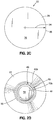
- FIG. 2C is an illustration of a top view of the fastener 10, such as in the form of fastener 10b, of FIG. 2A .
- FIGS. 1C and 2C show the top end 26 of the head portion 22 having a top surface 36, which is flat or substantially flat.
- FIGS. 1C and 2C further show the top end 26 of the head portion 22 having an outer periphery 38 (see also FIGS. 1A, 2A ) or perimeter.
- the fastener 10 (see FIGS. 1A, 2A ), such as in the form of fastener 10a (see FIG. 1A ), and such as in the form of fastener 10b (see FIG. 2A ), has a radial axis 84 (see FIGS. 1C, 2C ).
- the fastener 10 such as in the form of fastener 10a (see FIGS. 1A-1B ), and such as in the form of fastener 10b (see FIGS. 2A-2B, 2E ), respectively, further has a threaded portion 42 disposed at the second end 18 of the elongated shaft 14.
- the threaded portion 42 has a top end 44, a bottom end 46, a central portion 48 with an outer surface 50 comprised of a plurality of threads 52, and an interior 54.
- the threaded portion 42 may be configured to mate with a threaded collar 158 (see FIGS. 5A-5B ), a threaded nut, or another suitable threaded element.
- the fastener 10 such as in the form of fastener 10a, comprises an opening 40, such as a slot opening 40a, at the threaded portion 42.
- the opening 40 (see FIG. 1B ), such as the slot opening 40a (see FIGS. 1A-1B ), is preferably formed in a bottom surface 56 (see FIG. 1B ) at the bottom end 46 (see FIG. 1B ) of the threaded portion 42 (see FIG. 1B ).
- the slot opening 40a (see FIGS. 1A-1B ) is preferably a through opening going from one side of the fastener 10 through to the opposite side of the fastener 10.
- the threaded portion 42 has a cone-shaped tip portion 55 formed at the bottom end 46 (see FIG. 1B ).
- FIG. 1D is an illustration of a bottom view of the fastener 10, such as in the form of fastener 10a, of FIG. 1A .
- FIG. 1D shows the opening 40, such as the slot opening 40a, formed in the bottom surface 56 (see FIG. 1B ), and further shows a feed channel 70, such as in the form of a central feed channel 70a, and further shows the bottom of the shaft body 20 and the head portion 22.
- the fastener 10 such as in the form of fastener 10b, comprises an opening 40, such as a concentric ring opening 40b, at the threaded portion 42.
- the opening 40 such as the concentric ring opening 40b, is preferably formed at the top end 44 of the threaded portion 42.
- the threaded portion 42 has a bottom surface 56 that is flat or substantially flat at the bottom end 46 (see FIG. 2B ).
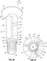
- FIG. 2D is an illustration of a bottom view of the fastener 10, such as in the form of fastener 10b, of FIG. 2A .
- FIG. 2D shows the bottom surface 56 at the bottom end 46, shows the opening 40, such as the concentric ring opening 40b, and shows the bottom of the shaft body 20 and the head portion 22.
- the fastener 10 such as in the form of fastener 10a (see FIGS. 1A-1B ), and such as in the form of fastener 10b (see FIGS. 2A-2B ), respectively, further comprises the shaft body 20 having a first end 58 integrally joined, connected, or coupled to the top end 44 of the threaded portion 42, has a second end 60 integrally joined, connected, or coupled to the bottom end 28 of the head portion 22, and has a central portion 62 disposed between the first end 58 and the second end 60.
- the shaft body 20 (see FIGS. 1A-1B, 2A-2B, 2E ) has an outer surface 64 (see FIGS. 1A-1B, 2A-2B, 2E ) and an inner surface 66 (see FIGS. 1B, 2B ), and further has an interior 68 (see FIGS. 1B, 2B ) and shaft body walls 168 (see FIGS. 1B , 2B , 2E ).
- the outer surface 64 of the shaft body 20 comprises a ridged outer surface 64a having a plurality of ridges 82.
- the plurality of ridges 82 are preferably configured to contact an inner hole surface 86 (see FIGS.
- FIGS. 5A-5B of a corresponding fastener hole 11 (see FIGS. 5A-5B ), to provide an electrical interconnection 90 (see FIG. 5B ) with a composite structure 102 (see FIG. 5B ), and to provide a fuel seal 92 (see FIG. 5B ) for a fastened joint 108 (see FIGS. 3A-3C ) formed by the fastener 10 (see FIGS. 3B , 3C , 5B ) fastened to the composite structure 102 (see FIGS. 3B , 3C , 5B ).
- the outer surface 64 of the shaft body 20 comprises a smooth outer surface 64b.
- the smooth outer surface 64b (see FIGS. 2A-2B ) is preferably smooth, or substantially smooth, and does not have a plurality of ridges 82 (see FIG. 1A ).
- the shaft body 20 of the fastener 10 such as in the form of fastener 10b, may further comprise one or more longitudinal grooves 87 extending from the concentric ring opening 40b at the top end 44 of the threaded portion 42, through the outer surface 64, such as the smooth outer surface 64b, of the shaft body, parallel to a longitudinal central axis 78 (see FIG. 2B ) of the elongated shaft 14, and terminating proximal to the head portion 22.
- FIG. 2F is an illustration of a bottom view of the fastener 10, such as in the form of fastener 10b, of FIG. 2E , showing the longitudinal grooves 87.
- the one or more longitudinal grooves 87 may comprise a first longitudinal groove 87a (see FIGS. 2E-2F ) and a second longitudinal groove 87b (see FIG. 2F ).
- Each longitudinal groove 87 may have a first end 91a (see FIG. 2E ) and a second end 91b (see FIG. 2E ).
- the longitudinal groove 87 opens through to a central bore portion 89 of the elongated shaft 14 of the fastener 10, such as in the form of fastener 10b.
- FIG. 2F shows the bottom surface 56 at the bottom end 46, shows the opening 40, such as the concentric ring opening 40b, shows a feed channel 70, such as in the form of a concentric ring feed channel 70b, shows the longitudinal grooves 87, and further shows the bottom of the shaft body 20 and the head portion 22.
- the fastener 10 such as in the form of fastener 10a (see FIG. 1B ), and such as in the form of fastener 10b (see FIG. 2B, 2E ), respectively, further has at least one feed channel 70 extending from the opening 40 at the threaded portion 42.
- the feed channel 70 may be in the form of a central feed channel 70a.
- the feed channel 70 may be in the form of a concentric ring feed channel 70b.
- the feed channel 70 may also have another suitable form or configuration.
- the feed channel 70 has a first end 72 and a second end 74. As further shown in FIGS. 1B and 2B , the feed channel 70 extends from the opening 40 at the threaded portion 42, through the inner surface 66 of the shaft body 20, parallel to a longitudinal central axis 78 of the elongated shaft 14, and terminates at a location 76 proximal to the head portion 22.
- the feed channel 70 extends longitudinally and parallel to the longitudinal central axis 78 (see FIGS. 1B, 2B ) of the elongated shaft 14 (see FIGS. 1B, 2B ), and the feed channel 70 (see FIGS. 1B, 2B ) has an interior 80 (see FIGS. 1B, 2B ).
- the interior 80 may comprise a through interior 80a that opens from one side of the shaft body 20 to the opposite side of the shaft body 20.
- the feed channel 70 such as in the form of central feed channel 70a, may be formed longitudinally, continuously, and centrally through the opening 40 at the bottom end 46 of the threaded portion 42, through the interior 54 of the threaded portion 42, through the interior 68 of the shaft body 20, and preferably terminates at the location 76 proximal to or slightly below the bottom end 28 of the head portion 22.
- the feed channel 70 such as in the form of concentric ring feed channel 70b, may be formed longitudinally and continuously through the opening 40 at or near the top end 44 of the threaded portion 42 and the first end 58 of the shaft body 20, through the interior 68 of the shaft body 20, and preferably terminates at the location 76 proximal to or slightly below the bottom end 28 of the head portion 22.
- the interior 80 (see FIG. 2B ) of the feed channel 70 (see FIG. 2B ), such as in the form of concentric ring feed channel 70b (see FIG. 2B ), is preferably a hollow concentric ring formed in the interior 68 (see FIG. 2B ) of the shaft body 20 (see FIG. 2B ), and is configured to receive the resin filler 120 (see FIGS. 5A-5B ) that is injected, under pressure, into the feed channel 70 (see FIG. 2B ).
- the shaft body 20 further has shaft body walls 168 (see FIG. 5B ), each having a wall thickness of between about 0.020 inch to about 0.060 inch.
- the wall thickness of the shaft body walls 168 (see FIGS. 1B, 5B ) of the fastener 10, such as fastener 10a (see FIGS. 1B, 5B ) may be in a range of between about 0.020 inch and about 0.030 inch.
- the wall thickness of the shaft body walls 168 (see FIGS. 2B, 2E ) of the fastener 10, such as fastener 10b (see FIGS. 2B, 2E ) may be in a range of between about 0.040 inch and about 0.060 inch. Electrical conduction may primarily be achieved through the shaft body walls 168 (see FIG. 5B ).
- the shaft body 20 (see FIGS. 1B, 2B ) of the fastener 10 (see FIGS. 1B, 2B ), including the shaft body walls 168 (see FIG. 5B ), are configured to radially expand upon injection, under pressure, of the resin filler 120 (see FIGS. 3A-3C, 5A-5B ) into the feed channel 70 (see FIGS. 1B, 2B, 2E, 5A-5B ), when the fastener 10 (see FIGS. 1B, 2B, 2E, 5A-5B ) is installed in a corresponding fastener hole 11 (see FIGS. 3B, 3C, 5A-5B ) formed in a composite structure 102 (see FIGS. 3B, 3C, 5A-5B ).
- the shaft body 20 (see FIGS. 1B , 2B , 2E ) of the fastener 10 (see FIGS. 1B , 2B , 2E ), including the shaft body walls 168 (see FIG. 1B , 2B , 2E , 5B ), may be configured to radially expand a radial distance of from about 0.001 inch to about 0.002 inch radially outward upon injection, under pressure, and filling with the resin filler 120 (see FIG. 5B ).
- the outer surface 64 (see FIGS. 1B, 2B ) of the shaft body 20 (see FIGS. 1B, 2B ) is configured to make direct contact with an inner hole surface 86 (see FIGS. 5A-5B ) of the corresponding fastener hole 11 (see FIGS. 3B, 3C, 5A-5B ), resulting in the fastener 10 (see FIGS. 3B, 3C, 5A-5B ) providing electrical contact 88 (see FIG. 5B ) with the composite structure 102 (see FIG. 5B ) and providing distribution of electric current 152 (see FIG. 5B ) to the composite structure 102 (see FIGS. 5B, 7 ), for example, electric current 152 (see FIG.
- the fastener 10 preferably provides improved electrical contact 88 (see FIG. 5B ) with the composite structure 102 (see FIGS. 5A-5B ) and improved distribution of electric current 152 (see FIG. 5B ) to the composite structure 102 (see FIG. 7 ).
- the fastener 10 such as in the form of fastener 10a (see FIGS. 1A-1B ), and such as in the form of fastener 10b (see FIGS. 2A-2B, 2E ), comprises a compliant clearance fit fastener 12, that when used with the resin filler 120 (see FIGS. 5A-5B ) that causes the shaft body 20 (see FIGS. 5A-5B ) to radially expand, results in the head portion 22 (see FIGS. 5A-5B ) and the shaft body 20 (see FIGS. 5B ) both having an interference fit 150 (see FIG. 5B ), or effective interference fit, with the inner hole surface 86 (see FIG. 5B ) of the corresponding fastener hole 11 (see FIG. 5B ).
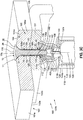
- FIG. 3A is an illustration of a partial cutaway side perspective view of the fastener system 100 of the disclosure.
- FIG. 3B is an illustration of a cutaway side perspective view of an example of a fastener system 100, such as in the form of fastener system 100a, shown with the fastener 10a of FIG. 1A .
- FIG. 3C is an illustration of a cutaway side perspective view another example of a fastener system 100, such as in the form of fastener system 100b, of the fastener system 100 of FIG. 3A shown with the fastener 10b of FIG. 2A .
- the fastener system 100 see FIGS.
- 3A-3C,5A-5B provides for improved electrical contact 88 (see FIG. 5B ) with the composite structure 102 (see FIGS. 3A-3C ), and improved distribution of electric current 152 (see FIG. 5B ) to the composite structure 102 (see FIG. 7 ), such as an aircraft composite structure 102b (see FIG. 7 ), and for example, electric current 152 (see FIG. 5B ) such as that resulting from a lightning strike 170 (see FIG. 7 ) or other electromagnetic effects or electrical events.
- the fastener system 100 (see FIGS. 3B, 3C ) comprises one or more fasteners 10 (see FIGS. 3B, 3C ), such as in the form of fastener 10a (see FIG. 3B ), and such as in the form of fastener 10b (see FIG. 3C ), as discussed above in detail above.
- the one or more fasteners 10 are each configured for installation into and within one or more corresponding fastener holes 11 (see FIGS. 3B, 3C ) formed in the composite structure 102 (see FIGS. 3A-3C ), such as a carbon fiber reinforced plastic (CFRP) structure 102a (see FIGS. 3A-3C ).
- the fastener 10 (see FIGS. 3B, 3C ) is configured to be filled with a resin filler 120 (see FIGS. 3B, 3C ).
- FIGS. 3B and 3C show the fastener 10 inserted into the corresponding fastener hole 11 in the composite structure 102, such as in the form of the carbon fiber reinforced plastic (CFRP) structure 102a.
- the top surface 36 (see FIGS. 3B, 3C ) of the top end 26 (see FIGS. 3B, 3C ) of the head portion 22 (see FIGS. 3B, 3C ) of the fastener 10 (see FIGS. 3B, 3C ) is shown in a countersink position 138 (see FIGS. 3B, 3C ).
- CFRP carbon fiber reinforced plastic
- CFRP carbon fiber reinforced plastic
- a matrix material 104 such as a resin matrix 104a (see FIGS. 3B, 3C ) reinforced with a plurality of fibers 105 (see FIGS. 3B, 3C ), such as carbon fibers 105a (see FIGS. 3B, 3C ), or a combination of carbon fibers 105a and other reinforcing fibers, such as glass fibers, aramid fibers, graphite fibers, aromatic polyamide fiber, fiberglass, aluminum fibers, or other suitable reinforcing fibers.
- the matrix material 104 see FIGS.
- thermoset polymer resins such as the resin matrix 104a (see FIGS. 3B, 3C ) of the CFRP preferably comprises a polymer resin comprising thermoset polymer resins or thermoplastic polymer resins.
- thermoset polymer resins include epoxy resins, polyester resins, phenolic resins, vinyl ester resins, allyl resins, bismaleimide (BMI) resins, polyurethane (PUR) resins, cyanate ester resins, polyimide resins, or other suitable thermoset polymer resins or resin systems.
- thermoplastic polymer resins that may be used include polyethylene (PE) resins, vinyl resins, polyproplyene (PP) resins, polyamide resins including nylon resins, polycarbonate resins, polyethylene terephthalate (PET) resins, polyetheretherketone polymer (PEEK) resins, polyetherketoneketone polymer (PEKK) resins, polyethersulfone (PES) resins, polysulfone (PSU) resins, polyphenylene sulfide (PPS) resins, polytetrafluoroethylene (PTFE) resins, or other suitable thermoplastic polymer resins or resin systems.
- PE polyethylene
- PP polyproplyene
- polyamide resins including nylon resins
- PET polyethylene terephthalate
- PEEK polyetheretherketone polymer
- PEKK polyetherketoneketone polymer
- PES polyethersulfone
- PSU polysulfone
- PPS polyphenylene sulfide
- the composite structure 102 comprises a first part 103a and a second part 103b.
- the first part 103a may be constructed of composite material, including the matrix material 104, such as the resin matrix 104a, and the plurality of fibers 105, such as carbon fibers 105a.
- the matrix material 104 such as the resin matrix 104a
- the plurality of fibers 105 such as the carbon fibers 105a
- FIGS. 3B , 3C are only schematically represented in FIGS. 3B , 3C , as well as FIGS. 5A-5B .
- the plurality of fibers 105 see FIGS.
- 3B, 3C, 5A-5B extend through the matrix material 104 (see FIGS. 3B, 3C, 5A-5B ) and are positioned throughout the composite structure 102 (see FIGS. 3B, 3C, 5A-5B ), extending in a length direction, a width direction, or a combination of these directions, such as 0, 90,+/-45 degree orientations, and layered in a thickness direction of the composite structure 102 (see FIGS. 3B, 3C, 5A-5B ).
- the second part 103b may comprise a metallic structure 107 (see FIGS. 3B, 3C ) made of a metal material, such as aluminum, or another suitable metal material, and fastened or attached to the first part 103a (see FIGS. 3B, 3C ) of the composite structure 102 (see FIGS. 3B, 3C ).
- the first part 103a (see FIGS. 3A-3C ) may comprise a metallic structure made of a metal material
- the second part 103b may comprise a composite material.
- the first part 103a has an interior opening 106a through which the fastener 10 is inserted
- the second part 103b has an interior opening 106b through which the fastener 10 is also inserted.
- the fastener 10 attaches or joins the first part 103a (see FIGS. 3B, 3C ) to the second part 103b (see FIGS. 3B, 3C ) to form a fastened joint 108 (see FIGS. 3A-3C ).
- each fastener 10 (see FIGS. 1B , 2B , 3B , 3C ) of the fastener system 100 (see FIGS. 3B, 3C ) comprises an elongated shaft 14 (see FIGS. 1B, 2B ) having a first end 16 (see FIGS. 1B, 2B ) with the head portion 22 (see FIGS. 1B , 2B , 3B , 3C ) disposed at the first end 16, a second end 18 (see FIGS. 1B, 2B ) with the threaded portion 42 (see FIGS. 1B , 2B , 3B , 3C ) disposed at the second end 18, and the shaft body 20 (see FIGS.
- the shaft body 20 (see FIGS. 1B, 2B ) has an outer surface 64 (see FIGS. 1B, 2B ) and an inner surface 66 (see FIGS. 1B, 2B ).
- Each fastener 10 (see FIGS. 1B , 2B , 3B , 3C ) of the fastener system 100 (see FIGS. 3B,3C ) further comprises, as discussed above, at least one feed channel 70 (see FIGS. 1B , 2B , 3B , 3C ) extending from an opening 40 (see FIGS. 1B , 2B , 3B , 3C ) at the threaded portion 42 (see FIGS. 1B , 2B , 3B , 3C ), through the inner surface 66 (see FIGS. 1B, 2B ) of the shaft body 20 (see FIGS.
- the opening 40 (see FIGS. 1B, 3B ) at the threaded portion 42 (see FIGS. 1B, 3B ) comprises a slot opening 40a (see FIGS. 1B, 3B ) at the bottom end 46 (see FIG. 1B ) of the threaded portion 42 (see FIGS.
- the opening 40 (see FIGS. 2B, 3C ) at the threaded portion 42 (see FIGS. 2B, 3C ) comprises a concentric ring opening 40b (see FIGS. 2B, 3C ) at the top end 44 (see FIG. 2B ) of the threaded portion 42 (see FIGS. 2B, 3C ).
- one or more longitudinal grooves 87 may be formed in the shaft body 20 and may extend from the concentric ring opening 40b, along the outer surface 64 of the shaft body 20, and terminate proximal to the head portion 22.
- the fastener system 100 further comprises an injection tool assembly 110 configured for coupling to each of the one or more fasteners 10, such as in the form of fastener 10a (see FIG. 3B ), and such as in the form of fastener 10b (see FIG. 3C ), installed in the one or more corresponding fastener holes 11.
- the injection tool assembly 110 is coupled to a bottom surface 112 of the second part 103b of the composite structure 102.
- the injection tool assembly 110 is coupled to the threaded portion 42 of the fastener 10.
- the injection tool assembly 110 (see FIGS. 3A-3C ) comprises one or more attachment portions 114 (see FIGS. 3A-3C ), such as in the form of suction cups or other suitable attachment element, for attachment to the bottom surface 112 (see FIGS. 3A-3C ) of the composite structure 102 (see FIGS. 3A-3C ).
- the attachment portion 114 (see FIGS. 3A-3C ) has a first end 116a (see FIGS. 3A-3C ) attached to the bottom surface 112 (see FIGS. 3A-3C ) of the second part 103b (see FIGS. 3A-3C ) of the composite structure 102 (see FIGS. 3A-3C ), and has a second end 116b (see FIGS. 3A-3C ).
- the attachment portion 114 is coupled to a vessel 118 with a pressure injector 126 that preferably contains the resin filler 120 (see FIGS. 3B, 3C ) for injection into the feed channel 70 (see FIGS. 3B, 3C ) of the fastener 10 (see FIGS. 3B, 3C ).
- the vessel 118 is coupled to, and held in place with, a holder assembly 128.
- the vessel 118 (see FIG. 3A ) with the pressure injector 126 (see FIG. 3A ) may be coupled or attached to a pressure assembly 129 (see FIG. 3A ) that provides pressure and power for injection of the resin filler 120 into the fastener 10.
- the vessel 118 (see FIGS. 3B, 3C ) is preferably configured for coupling, via the attachment portion 114 (see FIGS. 3B, 3C ), to the opening 40 (see FIGS. 3B, 3C ) at the threaded portion 42 (see FIGS. 3B, 3C ) of the fastener 10 (see FIGS. 3B, 3C ).
- the pressure injector 126 (see FIGS. 3B, 3C ) is preferably coupled to the opening 40 (see FIGS. 3B, 3C ) at the threaded portion 42 (see FIGS. 3B, 3C ) of the fastener 10 (see FIGS. 3B, 3C ), and is configured to inject the resin filler 120 (see FIGS. 3B, 3C ), under pressure, into the fastener 10 (see FIGS. 3B, 3C ).
- the injection tool assembly 110 may have one or more seal elements 136, such as in the form of O-ring pressure seals 136a, attached or coupled to the first end 116a of the attachment portion 114.
- the seal elements 136 (see FIGS. 3B, 3C ), such as in the form of high temperature O-ring pressure seals 136a (see FIGS. 3B, 3C ), preferably pressure seal the first end 116a (see FIGS. 3B, 3C ) of the attachment portion 114 (see FIGS. 3B, 3C ) against the bottom surface 112 (see FIGS. 3B, 3C ) of the composite structure 102 (see FIGS. 3B, 3C ).
- the pressure injector 126 preferably comprises a hollow injection tube 130 having a first end 132a with a first end opening 134a configured for injection of the resin filler 120 into the hollow injection tube 130.
- the hollow injection tube 130 has a second end 132b with a second end opening 134b configured for alignment with and coupling to the opening 40, such as the slot opening 40a, at the threaded portion 42 of the fastener 10, such as in the form of fastener 10a.
- the opening 40 such as the slot opening 40a
- the injection tool assembly 110 of the fastener system 100 injects or pumps, under pressure, the resin filler 120 up into the feed channel 70, such as the central feed channel 70a, of the fastener 10, such as in the form of fastener 10a, in order to fill the feed channel 70, such as the central feed channel 70a, with the resin filler 120.
- the hollow injection tube 130 may be configured to connect to a feed channel assembly 140 formed at one or more interior portions 142 of the attachment portion 114.
- the feed channel assembly 140 may comprise two or more lateral channels 144, each lateral channel 144 coupled at one end to the hollow injection tube 130, and each lateral channel 144 coupled at the other end to a concentric ring channel 146.
- the concentric ring channel 146 (see FIG. 3C ) is configured for alignment with and coupling to the opening 40 (see FIG. 3C ), such as the concentric ring opening 40b (see FIG. 3C ), at the top end 44 (see FIG. 2B ) of the threaded portion 42 (see FIG.
- the injection tool assembly 110 of the fastener system 100 injects or pumps, under pressure, the resin filler 120 up into the feed channel 70, such as the concentric ring feed channel 70b, of the fastener 10, such as in the form of fastener 10b, in order to fill the feed channel 70, such as the concentric ring feed channel 70b, with the resin filler 120.
- the fastener system 100 further comprises the resin filler 120 (see FIGS. 3B, 3C ) injected via the injection tool assembly 110 (see FIGS. 3B, 3C ) into each fastener 10 (see FIGS. 3B, 3C ) installed in the composite structure 102 (see FIGS. 3B, 3C ).
- the resin filler 120 (see FIGS. 3B, 3C ) is preferably formulated to achieve an effective viscosity level for dispensing into the feed channel 70 (see FIGS. 3B, 3C ) of the fastener 10 (see FIGS. 3B, 3C ), yet preferably not in a free flowing liquid state.
- the resin filler 120 preferably comprises a resin material 122 (see FIG. 5B ), such as a binding resin material or resin system, mixed with, filled with, or containing a filler material 124 (see FIG. 5B ), such as a conductive additive or filler, that is electrically conductive, or such as a nonconductive material.
- the resin material 122 may comprise a polymer resin comprising thermoset polymer resins or thermoplastic polymer resins.
- thermoset polymer resins that may be used include epoxy resins, polyester resins, phenolic resins, vinyl ester resins, allyl resins, bismaleimide (BMI) resins, polyurethane (PUR) resins, cyanate ester resins, polyimide resins, or other suitable thermoset polymer resins or resin systems.
- BMI bismaleimide
- PUR polyurethane
- thermoplastic polymer resins that may be used include polyethylene (PE) resins, vinyl resins, polyproplyene (PP) resins, polyamide resins including nylon resins, polycarbonate resins, polyethylene terephthalate (PET) resins, polyetheretherketone polymer (PEEK) resins, polyetherketoneketone polymer (PEKK) resins, polyethersulfone (PES) resins, polysulfone (PSU) resins, polyphenylene sulfide (PPS) resins, polytetrafluoroethylene (PTFE) resins, or other suitable thermoplastic polymer resins or resin systems.
- Exemplary resin materials 122 (see FIG. 5B ), or binding resin materials or resin systems, for the resin filler 120 comprise epoxy resins, bismaleimide (BMI) resins, phenolic resins, and cyanate ester resins.
- the filler material 124 may comprise, for example, chopped carbon fibers; carbon nanotubes; carbon nanofibers; carbon black; metallic fibers; metallic particles including silver particles, nickel particles, copper particles, and aluminum particles; graphite; graphene; graphene nanofillers; or other suitable conductive materials or nonconductive materials. Additionally, the filler material 124 (see FIG. 5B ) may comprise conductive polymers, such as poly(3,4-ethylenedioxythiophene) polystyrene sulfonate (PEDOT/PSS), polyaniline, polypyrrole, polyacetylene, polythiophene, or other suitable conductive polymers.
- PEDOT/PSS poly(3,4-ethylenedioxythiophene) polystyrene sulfonate
- PEDOT/PSS polyaniline
- polypyrrole polyacetylene
- polythiophene polythiophene
- conductive polymer also referred to as “intrinsically conducting polymer” means an organic polymer capable of conducting electricity.
- Exemplary filler materials 124 (see FIG. 5B ) for the resin filler 120 (see FIG. 5B ) comprise carbon nanotubes, chopped carbon fibers, silver particles, and the conductive polymer poly(3,4-ethylenedioxythiophene) polystyrene sulfonate (PEDOT/PSS).
- Exemplary resin fillers 120 comprise an epoxy resin doped with silver particles; a bismaleimide (BMI) resin doped with silver particles; a phenolic resin doped with silver particles; a cyanate ester resin doped with silver particles; an epoxy resin doped with carbon nanotubes; a bismaleimide (BMI) resin doped with carbon nanotubes; a phenolic resin doped with carbon nanotubes; a cyanate ester resin doped with carbon nanotubes; an epoxy resin with chopped carbon fibers; a bismaleimide (BMI) resin with chopped carbon fibers; a phenolic resin with chopped carbon fibers; a cyanate ester resin with chopped carbon fibers; and a resin with poly(3,4-ethylenedioxythiophene) polystyrene sulfonate (PEDOT/PSS).
- BMI bismaleimide
- PDOT poly(3,4-ethylenedioxythiophene) polystyrene sulfonate
- doped means mixed with, filled with, or containing, i.e., the resin is mixed with, filled with, or contains conductive material or additives, such as silver particles, carbon nanotubes, or chopped carbon fibers, to provide conductivity, such as electrical conductivity, or is mixed with, filled with, or contains nonconductive material.
- the resin material 122 (see FIG. 5B ), or resin system, of the resin filler 120 (see FIG. 5B ) has similar chemical properties, structural properties, and expansion characteristics as the fastener 10 (see FIGS. 1A, 2A, 5A-5B ) into which the resin material 122 (see FIG. 5B ) is inserted or injected.
- the resin filler 120 may have a conductivity, such as an electrical conductivity, of approximately 1 x 10 4 S/m (siemens per meter) or greater.
- conductivity and “electrical conductivity” mean the resin filler's ability to conduct an electric current.
- the conductivity, such as the electrical conductivity, of the resin filler 120 approaches the conductivity, such as the electrical conductivity, of the composite material of the composite structure 102 (see FIGS. 5A-5B ), along the direction of the carbon fibers 105a (see FIGS. 5A-5B ) of the composite material comprising the composite structure 102 (see FIGS. 3B, 3C, 5A-5B ).
- the resin filler 120 (see FIGS. 3B, 3C, 5A-5B ) is selected so that a coefficient of thermal expansion (CTE) of the resin filler 120 (see FIGS. 3B, 3C, 5A-5B ) substantially matches or matches a coefficient of thermal expansion (CTE) of the fastener 10 (see FIGS. 3B, 3C, 5A-5B ).
- CTE coefficient of thermal expansion
- the "coefficient of thermal expansion (CTE)” means a change in length or volume (e.g., linear thermal expansion in inches) of a material for a unit change in temperature (e.g., per degree Fahrenheit or Celsius), and is used to determine the rate at which a material expands as a function of temperature, and may be used to determine if thermal stress issues may occur.
- CTE coefficient of thermal expansion
- Polymeric plastics tend to expand and contract anywhere from six (6) to nine (9) times more than metals, and differences in CTE between adjacent materials may lead to internal stresses and stress concentrations in the polymer, which may cause premature microcracking to occur.
- the resin filler 120 see FIGS.
- 3B, 3C, 5A-5B is preferably selected so that the CTE of the resin filler 120 (see FIGS. 3B, 3C, 5A-5B ) substantially matches or matches the CTE of the fastener 10 (see FIGS. 1A, 2A, 5A-5B ), so that internal stress is not generated in the typical ground to altitude temperature variations that are typically experienced in aircraft 200a (see FIG. 7 ) and that could lead to micro-cracks in fastened composite joints.
- the fastener system 100 may further comprise a removable plug device 94 (see FIG. 5B ) configured for temporary insertion into the opening 40 (see FIG. 5B ) of the feed channel 70 (see FIG. 5B ) to prevent leakage of the resin filler 120 (see FIG. 5B ) out of the fastener 10 (see FIG. 5B ), after the resin filler 120 (see FIG. 5B ) is injected into the feed channel 70 (see FIG. 5B ) of the fastener 10 (see FIG. 5B ), and before the resin filler 120 (see FIG. 5B ) is cured in place.
- a removable plug device 94 see FIG. 5B
- FIG. 5B configured for temporary insertion into the opening 40 (see FIG. 5B ) of the feed channel 70 (see FIG. 5B ) to prevent leakage of the resin filler 120 (see FIG. 5B ) out of the fastener 10 (see FIG. 5B ), after the resin filler 120 (see FIG. 5B ) is injected into the
- FIG. 4 is a schematic diagram of a sectional side view of a known sleeved fastener 1, such as in the form of an interference fit sleeved fastener 1a, installed in a composite structure 102, such as a carbon fiber reinforced plastic (CFRP) structure 102a.
- the fastener 1 comprises a head portion 6, a shaft body 7, and a threaded portion 8.
- a sleeve 2 (see FIG. 4 ), such as a CRES (corrosion resistant steel) sleeve, surrounds the outside of the head portion 6 and the shaft body 7.
- a sealant 4 (see FIG. 4 ) is added over the sleeve 2 (see FIG. 4 ).
- a threaded collar 158 having a first end 160a and a second end 160b is threaded around the threaded portion 8 of the fastener 1.
- the fastener 1 has an interference fit 150 (see FIG. 4 ) at the head portion 6 (see FIG. 4 ) and along the shaft body 7 (see FIG. 4).
- FIG. 4 shows a distribution of electric current 152, which includes a head portion electric current distribution 153 and a shaft body electric current distribution 154, and shows the electric current 152 being distributed or transferred along a full sleeve length 156 of the fastener 1.
- the distribution of electric current 152 is uniform through the composite structure 102 (see FIG. 4 ), such as a carbon fiber reinforced plastic (CFRP) structure 102a (see FIG. 4 ), along the full sleeve length 156 (see FIG. 4 ) of the fastener 1 (see FIG. 4 ).
- the fastener 1 (see FIG. 4 ) is wet installed to ensure a fuel seal.
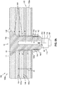
- FIG. 5A is a schematic diagram of a partial sectional side view of the fastener 10, such as in the form of fastener 10a, to further illustrate the fastener system 100, such as the fastener system 100a, of FIG. 3B of the disclosure.
- FIG. 5A shows the fastener 10, such as in the form of fastener 10a, installed in a composite structure 102, such as a carbon fiber reinforced plastic (CFRP) structure 102a, having a corresponding fastener hole 11 that may have a rough surface.
- CFRP carbon fiber reinforced plastic
- the composite structure 102 such as a carbon fiber reinforced plastic (CFRP) structure 102a, comprises the matrix material 104, such as the resin matrix 104a, mixed with the plurality of fibers 105, such as carbon fibers 105.
- the composite structure 102 (see FIGS. 5A, 7 ) preferably comprises an aircraft composite structure 102b (see FIG. 7 ).
- FIG. 5A further shows the resin filler 120 being injected into the fastener 10 to fill the interior 80 of the feed channel 70, such as the central feed channel 70a.
- the fastener 10 such as in the form of fastener 10a, comprises the head portion 22, the shaft body 20, and the threaded portion 42.
- the head portion 22 (see FIG. 5A ) of the fastener 10 is in a countersink position 138 (see FIG. 5A ) within the corresponding fastener hole 11 (see FIG. 5A ) of the composite structure 102 (see FIG. 5A ).
- the plurality of ridges 82 on the shaft body 20 of the fastener 10 are adjacent and in direct contact with the inner hole surface 86 of the corresponding fastener hole 11.
- the fastener 10 has a clearance fit 148.
- a threaded collar 158 may preferably be coupled to the threaded portion 42 of the fastener 10 to tighten and help hold the fastener 10 in place within the corresponding fastener hole 11 in the composite structure 102.
- the threaded collar 158 has a first end 160a adjacent the lower end of the composite structure 102 and has a second end 160b.
- the resin filler 120 is preferably injected or deposited into the fastener 10 (see FIG. 5A ) with the injection tool assembly 110 (see FIG. 5A ).
- the injection tool assembly 110 having a pressure injector 126 coupled to a vessel 118 containing the resin filler 120.
- the resin filler 120 (see FIG. 5A ) comprises a resin material 122 (see FIG. 5B ) mixed with, containing, or filled with a filler material 124 (see FIG. 5B ) that may or may not be electrically conductive.
- the injection tool assembly 110 may be provided with pressure and power by the pressure assembly 129, as shown in FIG. 3A , or another suitable power and pressure source or device.
- the pressure injector 126 (see FIG. 5A ) and the vessel 118 (see FIG. 5A ) may comprise similar components and a similar construction to the pressure injector 126 (see FIG. 3B ) and the vessel 118 (see FIG. 3B ) shown in FIG. 3B , or may comprise other suitable known pressure injector and vessel components used in known fluid pressure injection processes.
- FIG. 5A shows an arrow indicating the flow path of the resin filler 120 into the fastener 10.
- the resin filler 120 flows, under pressure, via the injection tool assembly 110 (see FIG. 5A ), into the fastener 10 (see FIG. 5A ) through the opening 40 (see FIG. 5A ) of the head portion 22 (see FIG. 5A ) at the threaded portion 42 (see FIG. 5A ), and proceeds to flow up into and through the feed channel 70 (see FIG. 5A ), such as in the form of central feed channel 70a (see FIG. 5A ), along a length 96 (see FIG. 5A ) of the shaft body 20 (see FIG. 5A ).
- the fastener 10 may preferably be cured.
- FIG. 5B is a schematic diagram of a partial sectional side view of the fastener system 100 of FIG. 5A showing the fastener 10, such as in the form of fastener 10a, filled with the resin filler 120, and showing radial expansion 162 of the fastener 10 and distribution of electric current 152.
- FIG. 5B shows the fastener 10, such as in the form of fastener 10a, installed in the composite structure 102, such as the carbon fiber reinforced plastic (CFRP) structure 102a, having the corresponding fastener hole 11.
- CFRP carbon fiber reinforced plastic
- the composite structure 102 such as the carbon fiber reinforced plastic (CFRP) structure 102a, comprises the matrix material 104, such as the resin matrix 104a, mixed with the plurality of fibers 105, such as carbon fibers 105.
- FIG. 5B further shows the feed channel 70, such as the central feed channel 70a, filled with the resin filler 120, comprising resin material 122 mixed with filler material 124.
- CFRP carbon fiber reinforced plastic
- the fastener 10 such as in the form of fastener 10a, comprises the head portion 22, the shaft body 20, and the threaded portion 42.
- the head portion 22 (see FIG. 5B ) of the fastener 10 is in the countersink position 138 (see FIG. 5B ) within the corresponding fastener hole 11 (see FIG. 5B ) of the composite structure 102 (see FIG. 5B ).
- the plurality of ridges 82 on the shaft body 20 of the fastener 10 are adjacent and in direct contact with the inner hole surface 86 of the corresponding fastener hole 11.
- the plurality of ridges 82 may function or serve to provide an electrical interconnection 90 (see FIG. 5B ) between the fastener 10 (see FIG. 5B ) and the inner hole surface 86 (see FIG. 5B ), and may also function or serve as a fuel seal 92 (see FIG. 5B ), that is reliable, for the fastened joint 108 (see FIGS. 3A-3C ).
- the threaded collar 158 having the first end 160a adjacent the lower end of the composite structure 102, and having the second end 160b, may preferably be coupled to the threaded portion 42 of the fastener 10 to tighten and help hold the fastener 10 in place within the corresponding fastener hole 11 in the composite structure 102.
- a removable plug device 94 may be temporarily inserted into the opening 40 of the feed channel 70 to prevent leakage of the resin filler 120 out of the fastener 10, after the resin filler 120 is injected into the feed channel 70 of the fastener 10.
- the removable plug device 94 may be removed after curing the fastener 10 (see FIG. 5B ) and the resin filler 120 (see FIG. 5B ), or the plug device 94 (see FIG. 5B ) may remain attached to the fastener 10 (see FIG. 5B ) after curing and removed at a later time.
- the opening 40 (see FIG. 5B ) of the fastener 10 see FIG.
- the removable plug device 94 may be inserted into the end of the feed channel 70 (see FIG. 5B ) of the fastener 10 (see FIG. 5B ) after the resin filler 120 (see FIG. 5B ) has been injected, so that a production tool may be moved to a next site and no time is taken waiting for the resin material 122 (see FIG. 5B ) of the resin filler 120 (see FIG. 5B ) to cure.
- FIG. 5B shows a distribution of electric current 152, which includes a head portion electric current distribution 153 and a shaft body electric current distribution 154, and shows the electric current 152 being distributed or transferred at the head portion 22 of the fastener 10 and along the length 96 the shaft body 20 of the fastener 10.
- the distribution of electric current 152 (see FIG. 5B ), such as the shaft body electric current distribution 154 (see FIG. 5B ), is preferably uniform along the length 96 (see FIG. 5B ) of the shaft body 20 (see FIG. 5B ) that is radially expanded or has undergone radial expansion 162 (see FIG. 5B ).
- the radial expansion 162 provides electrical conductivity across the fastener-to-composite structure interface.
- the head portion electric current distribution 153 (see FIG. 5B ) is preferably greater than the shaft body electric current distribution 154 (see FIG. 5B ).
- the resin filler 120 (see FIG. 5B ), such as comprising the resin material 122 (see FIG. 5B ) with filler material 124 (see FIG. 5B ), for example, chopped carbon fiber or an equivalent, may be injected into the feed channel 70 (see FIG. 5B ) of the fastener 10 (see FIG. 5B ), and may also serve or function as a structural reinforcement 164 (see FIG. 5B ) for the fastened joint 108 (see FIGS. 3A-3C ).
- the radial expansion 162 (see FIG. 5B ) of the fastener 10 provides improved electrical contact 88 (see FIG. 5B ) with the composite structure 102 (see FIG. 5B ) and provides improved distribution of electric current 152 (see FIG. 5B ) to the composite structure 102 (see FIG. 5B ).
- Each of the fasteners 10 comprises a compliant clearance fit fastener 12 (see FIGS. 1B, 2B ), that when used with the resin filler 120 (see FIG. 5B ), that causes the shaft body 20 (see FIG. 5B ) to radially expand, provides an interference fit 150 (see FIG. 5B ) at the head portion 22 (see FIG.
- the fastener 10 (see FIG. 5B ) and along the shaft body 20 (see FIG. 5B ).
- the fastener 10 (see FIG. 5B ) provides a lightning protection design 166 (see FIG. 5B ) that is effective and increases the current carrying capacity of the fastened joint 108 (see FIGS. 3A-3C ).
- FIG. 6 in another example there is provided a method 180 for providing improved electrical contact 88 (see FIG. 5B ) with a composite structure 102 (see FIG. 5B ) of an aircraft 200a (see FIG. 7 ) and improved distribution of electric current 152 (see FIG. 5B ) to the aircraft 200a (see FIG. 7 ), for example, electric current 152 (see FIG. 5B ) from a lightning strike 170 (see FIG. 7 ) or other electromagnetic effects or electrical events.
- FIG. 6 is a flow diagram showing an example of the method 180 of the disclosure.
- the method 180 comprises step 182 of installing one or more fasteners 10 (see FIGS. 1A, 2A, 5A-5B ), such as fastener 10a (see FIGS. 1A, 5A-5B ), or fastener 10b (see FIG. 2A ), into one or more corresponding fastener holes 11 (see FIGS. 3B, 3C, 5A-5B ) formed in the composite structure 102 (see FIGS. 3B, 3C, 5A-5B ).
- the fastener 10 see FIGS. 1A, 2A, 5A-5B
- the corresponding fastener hole 11 see FIGS.
- 3B, 3C, 5A-5B such as in the form of a discrete through-hole, is preferably formed, such as by drilling or another suitable forming process, into the composite structure 102 (see FIGS. 3B, 3C, 5A-5B ) with a known forming device, such as a drill or other suitable hole forming device.
- a known forming device such as a drill or other suitable hole forming device.
- the corresponding fastener hole 11 Before the fastener 10 (see FIGS. 3B, 3C, 5A-5B ) is installed in the corresponding fastener hole 11 (see FIGS. 3B, 3C, 5A-5B ), which has been formed, the corresponding fastener hole 11 (see FIGS. 3B, 3C, 5A-5B ) may be cleaned or prepared, if needed or desired, with a suitable cleaning or preparation device, cleaning or preparation agent, and/or cleaning or preparation method known in the art.
- a threaded collar 158 may preferably be coupled to the threaded portion 42 (see FIGS. 5A-5B ) of the fastener 10 (see FIGS. 5A-5B ) to help hold the fastener 10 (see FIGS. 5A-5B ) in place within the corresponding fastener hole 11 (see FIGS. 5A-5B ) in the composite structure 102 (see FIGS. 5A-5B ).
- each fastener 10 comprises, as discussed above, an elongated shaft 14 (see FIGS. 1A, 2A ) having a first end 16 (see FIGS. 1A,2A ) with a head portion 22 (see FIGS. 1A, 2A ), a second end 18 (see FIGS. 1A, 2A ) with a threaded portion 42 (see FIGS. 1A,2A ), and a shaft body 20 (see FIGS. 1A , 2A , 3A ) disposed between the first end 16 (see FIGS. 1A, 2A ) and the second end 18 (see FIGS. 1A, 2A ).
- the shaft body 20 (see FIGS. 1A, 2A ) has an outer surface 64 (see FIGS. 1A, 2A ) and an inner surface 66 (see FIGS. 1B, 2B ).
- Each fastener 10 further comprises, as discussed above, at least one feed channel 70 (see FIGS. 1B, 2B ) extending from an opening 40 (see FIGS. 1B, 2B ) at the threaded portion 42 (see FIGS. 1B, 2B ), through the inner surface 66 (see FIGS. 1B, 2B ) of the shaft body 20 (see FIGS. 1B, 2B ), parallel to a longitudinal central axis 78 (see FIGS. 1B, 2B ) of the elongated shaft 14 (see FIGS. 1B, 2B ), and terminating at a location 76 (see FIGS. 1B, 2B ) proximal to the head portion 22 (see FIGS. 1B, 2B ).
- the step 182 (see FIG. 6 ) of installing the one or more fasteners 10 may comprise installing the one or more fasteners 10 (see FIGS. 1A, 2A ), wherein the opening 40 (see FIGS. 1B, 2B ) at the threaded portion 42 (see FIGS. 1B, 2B ) comprises one of a slot opening 40a (see FIG. 1B ) at a bottom end 46 (see FIG. 1B ) of the threaded portion 42 (see FIG. 1B ), and a concentric ring opening 40b (see FIG. 2B ) at a top end 44 (see FIG. 2B ) of the threaded portion 42 (see FIG. 2B ), or another suitable type of opening.
- the method 180 further comprises step 184 of torquing the one or more fasteners 10 (see FIGS. 3B, 3C, 5A-5B ) in place in the one or more corresponding fastener holes 11 (see FIGS. 3B, 3C, 5A-5B ).
- the injection tool assembly 110 (see FIGS. 3A-3C, 5A ) is preferably coupled to the threaded portion 42 (see FIGS. 3B , 3C , 5A ) of the fastener 10 (see FIGS. 3B , 3C , 5A ).
- the method 180 further comprises step 186 of injecting, under pressure, a resin filler 120 (see FIGS. 3B , 3C , 5A ) into the opening 40 (see FIGS. 3B , 3C , 5A ) at the threaded portion 42 (see FIGS. 3B , 3C , 5A ) of each fastener 10 (see FIGS. 3B , 3C , 5A ), and filling each feed channel 70 (see FIGS. 3B , 3C , 5A ) with the resin filler 120 (see FIGS. 3B , 3C , 5A ) to cause the shaft body 20 (see FIGS.
- the resin filler 120 (see FIGS. 3B , 3C , 5A ) is preferably injected or deposited into the fastener 10 (see FIGS. 3B , 3C , 5A ) with the injection tool assembly 110 (see FIGS. 3B , 3C , 5A ).
- the step 186 (see FIG. 6 ) of injecting, under pressure, the resin filler 120 (see FIGS. 3B, 3C, 5A-5B ) and filling the feed channel 70 (see FIGS. 3B, 3C, 5A-5B ) with the resin filler 120 (see FIGS. 3B, 3C, 5A-5B ) preferably comprises filling the feed channel 70 (see FIGS. 3B, 3C, 5A-5B ) with the resin filler 120 (see FIGS. 3B, 3C, 5A-5B FIGS. 3B, 3C, 5A-5B ) to radially expand at a radial expansion 162 (see FIG. 5B ) of from about 0.001 inch to about 0.002 inch.
- the step 186 (see FIG. 6 ) of injecting, under pressure, the resin filler 120 (see FIGS. 3B, 3C, 5A-5B ) and filling each feed channel 70 (see FIGS. 3B, 3C, 5A-5B ) with the resin filler 120 (see FIGS. 3B, 3C, 5A-5B ) preferably comprises using an injection tool assembly 110 (see FIGS. 3B , 3C , 5A ) to inject the resin filler 120 (see FIGS. 3B, 3C, 5A-5B ) into the fastener 10 (see FIGS. 3B, 3C, 5A-5B ).
- the injection tool assembly 110 comprises a vessel 118 containing the resin filler 120.
- the vessel 118 (see FIGS. 3B , 3C , 5A ) is preferably configured for coupling to the fastener 10 (see FIGS. 3B , 3C , 5A ).
- the injection tool assembly 110 further comprises a pressure injector 126 coupled to the vessel 118, and the pressure injector 126 is preferably configured to couple to the opening 40 at the threaded portion 42 of the fastener 10, such as fastener 10a (see FIGS. 1A, 5A ), and fastener 10b (see FIG. 2A ).
- the vessel 118 may also be configured to couple to the opening 40 (see FIGS. 3B , 3C , 5A ).
- the pressure injector 126 (see FIGS. 3B , 3C , 5A ) is preferably configured to inject the resin filler 120 (see FIGS. 3B , 3C , 5A ), under pressure, into the fastener 10 (see FIGS. 3B , 3C , 5A ).
- the step 186 (see FIG. 6 ) of injecting, under pressure, the resin filler 120 further comprises injecting the resin filler 120 (see FIGS. 5A-5B ) comprising a resin material 122 (see FIG. 5B ) mixed with a filler material 124 (see FIG. 5B ) that may or may not be electrically conductive.
- the resin filler 120 comprises the resin material 122 mixed with the filler material 124.
- exemplary resin materials 122 see FIG. 5B
- binding resin materials or resin systems, for the resin filler 120 see FIG.
- exemplary filler materials 124 may comprise carbon nanotubes, chopped carbon fibers, silver particles, and the conductive polymer poly(3,4-ethylenedioxythiophene) polystyrene sulfonate (PEDOT/PSS).
- Exemplary resin fillers 120 see FIGS.
- 5A-5B comprise an epoxy resin doped with silver particles; a bismaleimide (BMI) resin doped with silver particles; a phenolic resin doped with silver particles; a cyanate ester resin doped with silver particles; an epoxy resin doped with carbon nanotubes; a bismaleimide (BMI) resin doped with carbon nanotubes; a phenolic resin doped with carbon nanotubes; a cyanate ester resin doped with carbon nanotubes; an epoxy resin with chopped carbon fibers; a bismaleimide (BMI) resin with chopped carbon fibers; a phenolic resin with chopped carbon fibers; a cyanate ester resin with chopped carbon fibers; and a resin with poly(3,4-ethylenedioxythiophene) polystyrene sulfonate (PEDOT/PSS).
- BMI bismaleimide
- the step 186 (see FIG. 6 ) of injecting, under pressure, the resin filler 120 (see FIGS. 5A-5B ), further comprises selecting the resin filler 120 (see FIGS. 5A-5B ), so that a coefficient of thermal expansion (CTE) of the resin filler 120 (see FIGS. 5A-5B ) substantially matches a coefficient of thermal expansion (CTE) of the fastener 10 (see FIGS. 5A-5B ).
- the resin material 122 (see FIG. 5B ), or binding resin material or resin system, of the resin filler 120 (see FIG. 5B ) has similar chemical properties and similar structural properties as the materials that make up the fastener 10 (see FIGS. 1A, 2A, 2E, 5A-5B ).
- the method 180 may further optionally comprise, after the step 186 of injecting the resin filler 120 (see FIGS. 5A-5B ) into the fastener 10 (see FIGS. 5A-5B ), the step 188 of inserting a removable plug device 94 (see FIG. 5B ) into the opening 40 (see FIG. 5B ) of each feed channel 70 (see FIG. 5B ) of the fastener 10 (see FIG. 5B ), to prevent leakage of the resin filler 120 (see FIG. 5B ) out of the fastener 10 (see FIG. 5B ).
- the removable plug device 94 may be removed after curing the fastener 10 (see FIG. 5B ) and the resin filler 120 (see FIG. 5B ), or the removable plug device 94 may remain attached to the fastener 10 (see FIG. 5B ) after curing.
- the method 180 further comprises step 190 of curing the composite structure 102 (see FIG. 5B ) with the one or more fasteners 10 (see FIG. 5B ) installed in the composite structure 102 (see FIG. 5B ) and filled with the resin filler 120 (see FIG. 5B ).
- step 190 of curing the composite structure 102 (see FIG. 5B ) with the one or more fasteners 10 (see FIG. 5B ) installed in the composite structure 102 (see FIG. 5B ) and filled with the resin filler 120 (see FIG. 5B ).
- the curing step 190 may be performed using a known curing process, such as an autoclave curing process, a vacuum bag curing process, a combination autoclave and vacuum bagging curing process, a compression mold curing process, a resin transfer molding process, a room temperature curing process, or another suitable curing process.
- the curing may take place at an elevated, effective temperature or effective heat and/or effective pressure for an effective period of time, as required per material specifications to effectively cure a chosen resin filler 120 (see FIG. 5A ).
- the resin filler 120 see FIG. 5A
- hardens, where deposited, in the fastener 10 see FIG. 5A ).
- the curing temperature or heat and/or pressure needed depends on the type of resin filler 120 (see FIG. 5A ) chosen to be injected into the fastener 10 (see FIG. 5A ), and may thus vary.
- "curing” means undergoing a full or partial hardening process, with or without heat, and includes precuring or precured resins.
- the method 180 further comprises step 192 of providing electrical contact 88 (see FIG. 5B ) between each fastener 10 (see FIG. 5B ), such as fastener 10a (see FIGS. 1A, 5B ), and fastener 10b (see FIG. 2A ), and the inner hole surface 86 (see FIG. 5B ) of each corresponding fastener hole 11 (see FIG. 5B ), and providing distribution of the electric current 152 (see FIG. 5B ) such as resulting from the lightning strike 170 (see FIG. 7 ) to the aircraft 200a (see FIG. 7 ).
- the step 192 of providing electrical contact 88 (see FIG. 5B ) and providing distribution of the electric current 152 (see FIG. 5B ) comprises distributing a head portion electric current distribution 153 (see FIG. 5B ) and a shaft body electric current distribution 154 (see FIG. 5B ).
- the shaft body electric current distribution 154 is uniform along a length 96 of the shaft body 20 that is radially expanded, for example, undergone a radial expansion 162, and the head portion electric current distribution 153 is greater than the shaft body electric current distribution 154.
- 5B preferably has an interference fit 150 (see FIG. 5B ) at the head portion 22 with the composite structure 102 (see FIG. 5B ), and an interference fit 150 (see FIG. 5B ) through the shaft body 20 (see FIG. 5B ), with the composite structure 102 (see FIG. 5B ).
- FIG. 7 is an illustration of a perspective view of an air vehicle 200, such as an aircraft 200a, that may incorporate one or more composite structures 102, such as, for example, one or more aircraft composite structures 102b, having examples of the fasteners 10 (see FIGS. 1A, 2A ) of the disclosure.
- the composite structures 102 (see FIG. 7 ) comprise carbon fiber reinforced plastic (CFRP) structures 102a (see FIGS. 3A-3C, 5A-5B ).
- CFRP carbon fiber reinforced plastic
- the aircraft 200a comprises such components as a fuselage 202, a nose 204, a flight deck 206, wings 208, one or more propulsion units 210 or engines, and a tail 212 comprising a vertical stabilizer 214 and horizontal stabilizers 216.
- the air vehicle 200 such as aircraft 200a, shown in FIG. 7 is generally representative of a commercial passenger aircraft having one or more composite structures 102
- the teachings of the disclosed examples may be applied to other passenger aircraft.
- the teachings of the disclosed examples may be applied to cargo aircraft, military aircraft, rotorcraft, and other types of aircraft or aerial vehicles, as well as aerospace vehicles, satellites, space launch vehicles, rockets, and other aerospace vehicles.
- FIG. 8 is a flow diagram of an aircraft manufacturing and service method 300.
- FIG. 9 is a block diagram of an aircraft 320. Referring to FIGS. 8-9 , examples of the disclosure may be described in the context of the aircraft manufacturing and service method 300 as shown in FIG. 8 , and the aircraft 320 as shown in FIG. 9 .
- exemplary aircraft manufacturing and service method 300 may include specification and design 302 of the aircraft 320 (see FIG. 9 ) and material procurement 304.
- component and subassembly manufacturing 306 (see FIG. 8 ) and system integration 308 (see FIG. 8 ) of the aircraft 320 (see FIG. 9 ) takes place.
- the aircraft 320 (see FIG. 9 ) may go through certification and delivery 310 (see FIG. 8 ) in order to be placed in service 312 (see FIG. 8 ).
- service 312 see FIG. 8
- the aircraft 320 may be scheduled for routine maintenance and service 314 (see FIG. 8 ) which may also include modification, reconfiguration, refurbishment, and other suitable services.
- Each of the processes of the aircraft manufacturing and service method 300 may be performed or carried out by a system integrator, a third party, and/or an operator (e.g., a customer).
- a system integrator may include, without limitation, any number of aircraft manufacturers and major-system subcontractors.
- a third party may include, without limitation, any number of vendors, subcontractors, and suppliers.
- An operator may include an airline, leasing company, military entity, service organization, and other suitable operators.
- the aircraft 320 produced by the exemplary aircraft manufacturing and service method 300 may include an airframe 322 with a plurality of systems 324 and an interior 326.
- examples of the plurality of systems 324 may include one or more of a propulsion system 328, an electrical system 330, a hydraulic system 332, and an environmental system 334. Any number of other systems may be included.
- an aerospace example is shown, the principles of the disclosure may be applied to other industries, such as the automotive industry.
- Methods and systems embodied herein may be employed during any one or more of the stages of the aircraft manufacturing and service method 300 (see FIG. 8 ).
- components or subassemblies corresponding to component and subassembly manufacturing 306 may be fabricated or manufactured in a manner similar to components or subassemblies produced while the aircraft 320 (see FIG. 9 ) is in service 312 (see FIG. 8 ).
- one or more apparatus examples, method examples, or a combination thereof may be utilized during component and subassembly manufacturing 306 (see FIG. 8 ) and system integration 308 (see FIG. 8 ), for example, by substantially expediting assembly of or reducing the cost of the aircraft 320 (see FIG. 9 ).
- one or more of apparatus examples, method examples, or a combination thereof may be utilized while the aircraft 320 (see FIG. 9 ) is in service 312 (see FIG. 8 ), for example and without limitation, to maintenance and service 314 (see FIG. 8 ).
- the fastener 10 (see FIGS. 1A , 2A , 2E ), the fastener system 100 (see FIGS. 3A-3C, 5A-5B ), and the method 180 (see FIG. 6 ) provide a compliant clearance fit fastener 12 (see FIGS. 1A, 2A ) that is expandable and resin filled.
- the fastener 10 (see FIGS. 1A , 2A , 2E ) has a feed channel 70 (see FIGS. 1B , 2B , 5B ), such as in the form of a central feed channel 70a (see FIGS. 1B, 5B ), and such as in the form of a concentric ring feed channel 70b (see FIGS.
- the feed channel 70 (see FIGS. 1B, 2B, 2E, 5B ) has an interior 80 (see FIGS. 1B, 2B ) that is hollow and that is designed to radially expand, once it is inserted into a corresponding fastener hole 11 (see FIGS. 3B, 3C, 5A-5B ) and filled with a resin filler 120 (see FIG. 5B ) that forces or causes radial expansion 162 (see FIG. 5B ) of the shaft body 20 (see FIGS.
- the resin filler 120 also serves or functions as a structural reinforcement 164 (see FIG. 5B ) for the fastened joint 108 (see FIGS. 3A-3C ), and the resin filler 120 (see FIG. 5B ) does not necessarily need to have electrical conductivity characteristics, since electrical conduction may be primarily achieved through the shaft body walls 168 (see FIG. 5B ) of the fastener 10 (see FIG. 5B ).
- the compliant clearance fit fastener 12 (see FIGS. 1B, 2B ) is preferably configured for installation with a clearance fit 148 (see FIG. 5A ) in a corresponding fastener hole 11 (see FIG.
- the shaft body 20 (see FIG. 5B ) of the fastener 10 (see FIG. 5B ) is expandable and is configured to radially expand upon being filled with the resin filler 120 (see FIG. 5B ) that also provides structural reinforcement 164 (see FIG. 5B ).
- the type of resin filler 120 (see FIG. 5B ) used may be determined based on the design and intended applications of the fastener 10 (see FIGS. 1A,2A ) and fastener system 100 (see FIGS. 3A-3C, 5A-5B ) used.
- fastener 10 see FIGS. 1A , 2A , 2E
- the fastener system 100 see FIGS. 3A-3C, 5A-5B
- the method 180 see FIG. 6
- provide a lightning protection design 166 see FIG. 5B
- the fastener 10 see FIGS. 1A , 2A , 2E
- does not require a sleeve 2 see FIG. 4
- a sealant 4 see FIG. 4
- the fastener 10 see FIGS. 1A, 2A
- the fastener system 100 see FIGS.
- the fastener 10 (see FIGS. 1A , 2A , 2E ), the fastener system 100 (see FIGS. 3A-3C, 5A-5B ), and the method 180 (see FIG. 6 ) enable a fastened joint 108 (see FIGS. 3A-3C ) with an interference fit 150 (see FIG. 5B ) along the length 96 (see FIG.
- the fastener 10 (see FIGS. 1B , 2B , 2E , 5B ) is expandable and provides electrical current transfer at the head portion 22 (see FIG. 5B ) and along the shaft body 20 (see FIG. 5B ) or shank, once expanded after insertion into the drilled corresponding fastener hole 11 (see FIG. 5B ) and filled with the resin filler 120 (see FIG. 5B ).
- the fastener 10 see FIGS.
- 1A , 2A , 2E , 5B is preferably an inexpensive, sleeveless, expandable, compliant clearance fit fastener 12 (see FIGS. 1A, 2A ) that is used in conjunction with the resin filler 120 (see FIGS. 5B ) to yield the equivalent, or better, electrical conductivity and electrical contact 88 (see FIG. 5B ), as compared to that of known interference fit sleeved fasteners 1a (see FIG. 4 ).
- disclosed examples of the fastener 10 may provide for a reduced overall weight of an air vehicle 200 (see FIG. 7 ), such as an aircraft 200a (see FIG. 7 ), by decreasing the use of heavy electrically insulating sealants on the fasteners, for example, as used in aircraft fuel tanks, for protection against lightning strikes 170 (see FIG. 7 ) or other electromagnetic effects or electrical events, by decreasing the use of known sleeved fasteners 1 (see FIG. 4 ), such as interference fit sleeved fasteners 1a (see FIG.
- the fastener 10 may reduce the cost of lightning mitigation on composite structures 102 (see FIG. 7 ) of aircraft 200a (see FIG. 7 ) by employing the less expensive fasteners 10 (see FIGS. 1A , 2A , 2E ) disclosed herein that provide equivalent or better electrical connection to composite structures 102 (see FIGS. 3A-3C, 7 ), such as aircraft composite wing skins.
- the cost of secondary sealants and fastener cap seals may also be reduced with the disclosed fasteners 10 (see FIGS. 1A , 2A , 2E ) and fastener system 100 (see FIGS. 3A-3C ).
- a sealant 4 for example, a polysulfide resin
- the fastener 10 does not use a sleeve 2 (see FIG. 4 ) or a sealant 4 (see FIG. 4 ), and uses a resin filler 120 (see FIGS. 5A-5B ) to fill the feed channel 70 (see FIGS.
- the fastener 10 provides for a fastener having a reduced cost and a reduced weight that may be used in composite structures 102 (see FIG. 4 ), such as composite fuel tanks of aircraft 200a (see FIG. 7 ) to achieve good electrical contact 88 (see FIG. 5B ) between the fastener 10 (see FIG. 5B ) and the composite structure 102 (see FIG. 5B ), for example, a fastener-to-composite structure interface, thus increasing the current carrying capacity of the fastened joint 108 (see FIGS. 3A-3C ) formed by the fastener 10 (see FIG. 5B ) fastened to the composite structure 102 (see FIG. 5B ).
- CFRP carbon fiber reinforced plastic
- FIGS. 3A-3C, 5A-5B For lightning protection of carbon fiber reinforced plastic (CFRP) structures 102a (see FIGS. 3A-3C, 5A-5B ) with fastened joints 108 (see FIGS. 3B, 3C ), it is desirable to increase the lightning current carrying capacity of the fastened joints 108 (see FIGS. 3B, 3C ) by providing surface electrical contact area along the length 96 (see FIGS. 5A-5B ) of the fastener 10 (see FIGS. 5A-5B ) and the inner hole surface 86 (see FIG. 5B ) of the corresponding fastener hole 11 (see FIG. 5B ), through which the fastener 10, such as a metal fastener, is inserted into the composite structure 102 (see FIG. 5B ).
- CFRP carbon fiber reinforced plastic
- the compliant clearance fit fastener 12 may be used on wings 208 (see FIG. 7 ) of an aircraft 200a (see FIG. 7 ), and the radial expansion 162 (see FIG. 5B ) increases distribution of electric current 152 (see FIG. 5B ) through increased electrical contact 88 (see FIG. 5B ) between the shaft body 20 (see FIG. 5B ) of the fastener 10 (see FIG. 5B ) and the composite structure 102 (see FIG. 5B ), such as the CFRP structure 102a (see FIG. 5B ) or CFRP layup, during a lightning strike 170 (see FIG. 6 ).
- Increased current distribution increases EME (electromagnetic effect) characteristics.
- a fastener 10 having a shaft body 20 (see FIG. 1B ) with an outer surface 64 (see FIG. 1B ), such as in the form of a ridged outer surface 64a (see FIG. 1B ) having a plurality of ridges 82 (see FIG. 1B ), configured to contact the inner hole surface 86 (see FIG. 5B ) of a corresponding fastener hole 11 (see FIG. 5B ), to provide an electrical interconnection 90 (see FIG.
- the plurality of ridges 82 (see FIGS. 1B, 5B ) also provide a fuel seal 92 (see FIG. 5B ) for a fastened joint 108 (see FIGS. 3A-3C ) formed by the fastener 10 (see FIGS. 3B , 3C , 5B ) fastened to the composite structure 102 (see FIGS. 3B , 3C , 5B ).
- the plurality of ridges 82 (see FIG. 1B ) along the shaft body 20 may improve current distribution and may serve as an integral fuel seal once the shaft body 20 (see FIG. 5B ) is expanded.
Landscapes
- Engineering & Computer Science (AREA)
- General Engineering & Computer Science (AREA)
- Mechanical Engineering (AREA)
- Aviation & Aerospace Engineering (AREA)
- Manufacturing & Machinery (AREA)
- Connection Of Plates (AREA)
- Elimination Of Static Electricity (AREA)
Abstract
Description
- The disclosure relates generally to fasteners, fastener systems, and methods for composite structures, and more particularly, to expandable, compliant clearance fit fasteners, fastener systems, and methods that provide improved electrical contact and conductivity with composite structures, such as carbon fiber reinforced plastic (CFRP) structures, such as for use in aircraft.
- Composite structures, such as carbon fiber reinforced plastic (CFRP) structures, may be used in a wide variety of applications, including in the manufacture of aircraft, spacecraft, rotorcraft, watercraft, automobiles, trucks, and other vehicles and structures, due to their high strength-to-weight ratios, corrosion resistance, and other favorable properties. The composite structures, such as CFRP structures, are typically made of a composite material comprising a matrix material, such as a resin, reinforced with fiber material, such as carbon fiber. The resin is not generally electrically conductive, in contrast to the fiber material.
- Good electrical contact between composite aircraft wings, fuselage, or other aircraft structures, and metal fasteners, i.e., metal bolts, used to secure parts of such structures together, is important to provide electrical conductivity and current distribution or dissipation, such as in the event of a lightning strike or other electromagnetic effects and electrical events, in order for the electric current from the lightning strike to be distributed or dissipated and conducted to ground across the fastened joints and through the surface of the composite structure. If electrical contact between the metal fasteners and such composite aircraft structures, for example, composite wing skins, is inadequate, the electric current from the lightning strike may not dissipate, may remain in the vicinity of the struck fasteners, and may be conducted into the substructure and possibly a fuel tank in the wing, where unwanted discharge or sparking may occur as the result of electrical arching, and/or hot plasma particles ejected from joints due to decomposition of material systems, leading to a potential ignition source in a fuel environment.
- Known systems and methods exist to prevent or mitigate discharge and effects from lightning strikes in aircraft composite wing fuel tanks and other aircraft composite structures. Such known systems and methods include the application of electrically insulating sealants and the use of fastener cap seals to cover metal fasteners in the aircraft composite wing fuel tanks, to contain the discharge in the fastened joint.
- However, such known electrically insulating sealants may be heavy, and such known fastener seal caps may be numerous in number, and both may add weight to the aircraft, which may result in reduced performance and increased fuel consumption, and, in turn, may result in increased fuel costs. Moreover, such known electrically insulating sealants and fastener seal caps may be time consuming and labor intensive to apply or install and inspect in the aircraft composite wings and fuel tanks, or other aircraft structures, which, in turn, may result in increased manufacturing and inspection time and increased labor costs.
- In addition, known fasteners and fastener systems exist that achieve good electrical contact between composite aircraft structures, such as composite wing skins, and the metal fasteners used to secure such structures, and that reduce the potential for unwanted discharge or sparking in aircraft composite wing fuel tanks. Such known fasteners and fastener systems include the use of interference fit fasteners that employ a corrosion resistant steel (CRES) sleeve through which a tapered titanium bolt is inserted, i.e., sleeved interference fit fasteners. When torque is applied to a collar of the bolt, the sleeve expands, making contact with composite layers of the composite wing skin.
- However, such sleeved interference fit fasteners may be expensive and difficult to install, and the CRES sleeves for the interference fit fasteners may add weight to the fastened joints, which may result in increased fuel consumption, and, in turn, may result in increased operating costs. Further, due to the expansion of the fastener sleeve when torque is applied to the bolt collar, any exposed high conductivity carbon fiber tip in drilled holes, in which the fasteners are inserted, may be crushed, damaged, or possibly broken. This may limit the overall electrical connection and may also promote micro-cracks in the fastened joints of the composite structure.
- Moreover, to meet fuel seal requirements, such known sleeved interference fit fasteners are typically required to be wet installed, which involves immersing the sleeved interference fit fastener in a polysulfide fuel sealant prior to installation in a fastener hole in a composite structure. Such wet installation results in a thin layer of sealant being present between the fastener sleeve and a surface of the fastener hole, after the fastener is installed into the fastener hole. Although this sealant layer serves its fuel seal purpose, its presence may interfere with and decrease the efficiency of electrical current transfer across a fastener-to-composite structure interface.
- Accordingly, there is a need in the art for an improved fastener, fastener system, and method that is inexpensive, simple to install and use, weight saving, and reliable, and that provide advantages over known fastener devices, systems and methods.
- Example implementations of this disclosure provide an improved fastener, fastener system, and method for composite structures, such as carbon fiber reinforced plastic (CFRP) structures. As discussed in the below detailed description, embodiments of the improved fastener, fastener system, and method may provide significant advantages over known fastener devices, systems, and methods.
- In one example there is provided a fastener for providing improved electrical contact with a composite structure and improved distribution of electric current to the composite structure. The fastener comprises an elongated shaft having a first end, a second end, and a shaft body disposed between the first end and the second end. The shaft body has an outer surface and an inner surface.
- The fastener further comprises a head portion disposed at the first end. The fastener further comprises a threaded portion disposed at the second end. The fastener further comprises at least one feed channel extending from an opening at the threaded portion, through the inner surface of the shaft body, parallel to a longitudinal central axis of the elongated shaft, and terminating at a location proximal to the head portion.
- The shaft body is configured to radially expand upon injection, under pressure, of a resin filler into the at least one feed channel, when the fastener is installed in a corresponding fastener hole formed in the composite structure. Further, upon radially expanding, the outer surface of the shaft body is configured to make direct contact with an inner hole surface of the corresponding fastener hole, resulting in the fastener providing electrical contact with the composite structure and providing distribution of electric current to the composite structure.
- In another example there is provided a fastener system for providing improved electrical contact with a composite structure and improved distribution of electric current to the composite structure. The fastener system comprises one or more fasteners configured for installation in one or more corresponding fastener holes formed in the composite structure.
- Each fastener comprises an elongated shaft having a first end, a second end, and a shaft body disposed between the first end and the second end. The shaft body has an outer surface and an inner surface. The fastener further comprises a head portion disposed at the first end. The fastener further comprises a threaded portion disposed at the second end. The fastener further comprises at least one feed channel extending from an opening at the threaded portion, through the inner surface of the shaft body, parallel to a longitudinal central axis of the elongated shaft, and terminating at a location proximal to the head portion.
- The fastener system further comprises an injection tool assembly configured for coupling to each of the one or more fasteners installed in the one or more corresponding fastener holes. The fastener system further comprises a resin filler injected, under pressure, with the injection tool assembly into the at least one feed channel of each fastener to fill up the at least one feed channel to cause the shaft body to radially expand and to make direct contact with an inner hole surface of the corresponding fastener hole, resulting in the fastener providing electrical contact with the composite structure and providing distribution of electric current to the composite structure.
- In another example there is provided a method for providing improved electrical contact with a composite structure of an aircraft and improved distribution of electric current to the aircraft. The method comprises the step of installing one or more fasteners into one or more corresponding fastener holes formed in the composite structure.
- Each fastener comprises an elongated shaft having a first end with a head portion, a second end with a threaded portion, and a shaft body disposed between the first end and the second end. The shaft body has an outer surface and an inner surface. The fastener further comprises at least one feed channel extending from an opening at the threaded portion, through the inner surface of the shaft body, parallel to a longitudinal central axis of the elongated shaft, and terminating at a location proximal to the head portion.
- The method further comprises the step of torquing the one or more fasteners in place in the one or more corresponding fastener holes. The method further comprises the step of injecting, under pressure, a resin filler into the opening at the threaded portion of each fastener, and filling the at least one feed channel with the resin filler to cause the shaft body to radially expand and to make direct contact with an inner hole surface of the corresponding fastener hole.
- The method further comprises curing the composite structure with the one or more fasteners installed in the composite structure and filled with the resin filler. The method further comprises the step of providing electrical contact between each fastener and the inner hole surface of each corresponding fastener hole, and providing distribution of the electric current to the aircraft.
- The features, functions, and advantages that have been discussed can be achieved independently in various examples of the disclosure or may be combined in yet other examples, further details of which can be seen with reference to the following description and drawings.
- The disclosure can be better understood with reference to the following detailed description taken in conjunction with the accompanying drawings which illustrate examples, but which are not necessarily drawn to scale, wherein:
-
FIG. 1A is an illustration of a side perspective view of an example of a fastener of the disclosure; -
FIG. 1B is an illustration of a cutaway side perspective view of the fastener ofFIG. 1A ; -
FIG. 1C is an illustration of a top view of the fastener ofFIG. 1A ; -
FIG. 1D is an illustration of a bottom view of the fastener ofFIG. 1A ; -
FIG. 2A is an illustration of a side perspective view of another example of a fastener of the disclosure; -
FIG. 2B is an illustration of a cutaway side perspective view of the fastener ofFIG. 2A ; -
FIG. 2C is an illustration of a top view of the fastener ofFIG. 2A ; -
FIG. 2D is an illustration of a bottom view of the fastener ofFIG. 2A ; -
FIG. 2E is an illustration of a side perspective view of the fastener ofFIG. 2A having one or more optional longitudinal grooves; -
FIG. 2F is an illustration of a bottom view of the fastener ofFIG. 2E ; -
FIG. 3A is an illustration of a partial cutaway side perspective view of a fastener system of the disclosure; -
FIG. 3B is an illustration of a cutaway side perspective view of an example of a fastener system shown with the fastener ofFIG. 1A ; -
FIG. 3C is an illustration of a cutaway side perspective view another example of a fastener system shown with the fastener ofFIG. 2A ; -
FIG. 4 is a schematic diagram of a sectional side view of a known sleeved fastener installed in a composite structure and showing distribution of electric current; -
FIG. 5A is a schematic diagram of a partial sectional side view of an example of a fastener system of the disclosure showing the fastener installed in a composite structure and a resin filler injected into the fastener; -
FIG. 5B is a schematic diagram of a partial sectional side view of the fastener system ofFIG. 5A showing the fastener filled with the resin filler, and showing radial expansion of the fastener and distribution of electric current; -
FIG. 6 is a flow diagram showing an example of a method of the disclosure; -
FIG. 7 is an illustration of a perspective view of an aircraft that may incorporate composite structures having one or more examples of a fastener of the disclosure; -
FIG. 8 is a flow diagram of an aircraft manufacturing and service method; and, - [0001]
FIG. 9 is a block diagram of an aircraft. - Each figure shown in this disclosure shows a variation of an aspect of the examples presented, and only differences will be discussed in detail.
- Disclosed examples will now be described more fully hereinafter with reference to the accompanying drawings, in which some, but not all of the disclosed examples are shown. Indeed, several different examples may be provided and should not be construed as limited to the examples set forth herein. Rather, these examples are provided so that this disclosure will be thorough and fully convey the scope of the disclosure to those skilled in the art.
- Now referring to the Figures, in one example there is provided a
fastener 10, as shown inFIGS. 1A-2D .FIGS. 1A-1D show one example of thefastener 10, such as in the form offastener 10a.FIGS. 2A-2D show another example of thefastener 10, such as in the form offastener 10b. Preferably the fastener 10 (seeFIGS. 1A, 2A ), such as in the form offastener 10a (seeFIG. 1A ) and such as in the form offastener 10b (seeFIG. 2A ), comprises a compliant clearance fit fastener 12 (seeFIGS. 1A-1B, 2A-2B ) that is sleeveless, i.e., does not require an additional metal sleeve. The fastener 10 (seeFIGS. 1A, 2A ) may be comprised of a metal material, such titanium, aluminum, or another suitable metal, or a metal alloy, such as an alloy of nickel containing chromium and iron that is resistant to corrosion at high temperatures, or a nickel-copper alloy having a high tensile strength and resistance to corrosion, or another suitable metal alloy. -
FIG. 1A is an illustration of a side perspective view of an example of thefastener 10, such as in the form offastener 10a, of the disclosure.FIG. 1B is an illustration of a cutaway side perspective view of thefastener 10, such as in the form offastener 10a, ofFIG. 1A . -
FIG. 2A is an illustration of a side perspective view of another example of thefastener 10, such as in the form offastener 10b, of the disclosure.FIG. 2B is an illustration of a cutaway side perspective view of thefastener 10, such as in the form offastener 10b, ofFIG. 2A .FIG. 2E is an illustration of a side perspective view of thefastener 10, such as in the form offastener 10b, ofFIG. 2A , having one or more additional, optional,longitudinal grooves 87. - As shown in
FIGS. 1A-1B and 2A-2B, 2E , thefastener 10, such as in the form offastener 10a (seeFIGS. 1A-1B ), and such as in the form offastener 10b (seeFIGS. 2A-2B ), respectively, has an elongatedshaft 14 having afirst end 16, asecond end 18, and ashaft body 20 disposed between thefirst end 16 and thesecond end 18. As further shown inFIGS. 1A-2E , thefastener 10, such as in the form offastener 10a (seeFIGS. 1A-1B ), and such as in the form offastener 10b (seeFIGS. 2A-2B, 2E ), respectively, has ahead portion 22 disposed at thefirst end 16. The head portion 22 (seeFIGS. 1A-1B, 2B ) preferably has a frusto-conical shape 24 (seeFIGS. 1A-1B, 2B ). However, the head portion 22 (seeFIGS. 1A, 2A ) may have another suitable shape as well. As shown inFIGS. 1B ,2B , thehead portion 22 has atop end 26, abottom end 28, and acentral portion 30 with an outer surface 32 (see alsoFIGS. 1A, 2A ) and an interior 34. -
FIG. 1C is an illustration of a top view of thefastener 10, such as in the form offastener 10a, ofFIG. 1A .FIG. 2C is an illustration of a top view of thefastener 10, such as in the form offastener 10b, ofFIG. 2A .FIGS. 1C and2C show thetop end 26 of thehead portion 22 having atop surface 36, which is flat or substantially flat.FIGS. 1C and2C further show thetop end 26 of thehead portion 22 having an outer periphery 38 (see alsoFIGS. 1A, 2A ) or perimeter. The fastener 10 (seeFIGS. 1A, 2A ), such as in the form offastener 10a (seeFIG. 1A ), and such as in the form offastener 10b (seeFIG. 2A ), has a radial axis 84 (seeFIGS. 1C, 2C ). - As shown in
FIGS. 1A-1B and 2A-2B, 2E , thefastener 10, such as in the form offastener 10a (seeFIGS. 1A-1B ), and such as in the form offastener 10b (seeFIGS. 2A-2B, 2E ), respectively, further has a threadedportion 42 disposed at thesecond end 18 of theelongated shaft 14. As shown inFIGS. 1B ,2B , the threadedportion 42 has atop end 44, abottom end 46, acentral portion 48 with anouter surface 50 comprised of a plurality ofthreads 52, and an interior 54. The threadedportion 42 may be configured to mate with a threaded collar 158 (seeFIGS. 5A-5B ), a threaded nut, or another suitable threaded element. - In one example, as shown in
FIGS. 1A-1B , thefastener 10, such as in the form offastener 10a, comprises anopening 40, such as aslot opening 40a, at the threadedportion 42. The opening 40 (seeFIG. 1B ), such as theslot opening 40a (seeFIGS. 1A-1B ), is preferably formed in a bottom surface 56 (seeFIG. 1B ) at the bottom end 46 (seeFIG. 1B ) of the threaded portion 42 (seeFIG. 1B ). Theslot opening 40a (seeFIGS. 1A-1B ) is preferably a through opening going from one side of thefastener 10 through to the opposite side of thefastener 10. Further, in this example, as shown inFIGS. 1A-1B , the threadedportion 42 has a cone-shapedtip portion 55 formed at the bottom end 46 (seeFIG. 1B ). -
FIG. 1D is an illustration of a bottom view of thefastener 10, such as in the form offastener 10a, ofFIG. 1A .FIG. 1D shows theopening 40, such as theslot opening 40a, formed in the bottom surface 56 (seeFIG. 1B ), and further shows afeed channel 70, such as in the form of acentral feed channel 70a, and further shows the bottom of theshaft body 20 and thehead portion 22. - In another example, as shown in
FIGS. 2A-2B , thefastener 10, such as in the form offastener 10b, comprises anopening 40, such as aconcentric ring opening 40b, at the threadedportion 42. As further shown inFIGS. 2A-2B , theopening 40, such as theconcentric ring opening 40b, is preferably formed at thetop end 44 of the threadedportion 42. Further, in this example, as shown inFIGS. 2A-2B , the threadedportion 42 has abottom surface 56 that is flat or substantially flat at the bottom end 46 (seeFIG. 2B ). -
FIG. 2D is an illustration of a bottom view of thefastener 10, such as in the form offastener 10b, ofFIG. 2A .FIG. 2D shows thebottom surface 56 at thebottom end 46, shows theopening 40, such as theconcentric ring opening 40b, and shows the bottom of theshaft body 20 and thehead portion 22. - As shown in
FIGS. 1A-1B and 2A-2B , thefastener 10, such as in the form offastener 10a (seeFIGS. 1A-1B ), and such as in the form offastener 10b (seeFIGS. 2A-2B ), respectively, further comprises theshaft body 20 having afirst end 58 integrally joined, connected, or coupled to thetop end 44 of the threadedportion 42, has asecond end 60 integrally joined, connected, or coupled to thebottom end 28 of thehead portion 22, and has acentral portion 62 disposed between thefirst end 58 and thesecond end 60. - The shaft body 20 (see
FIGS. 1A-1B, 2A-2B, 2E ) has an outer surface 64 (seeFIGS. 1A-1B, 2A-2B, 2E ) and an inner surface 66 (seeFIGS. 1B, 2B ), and further has an interior 68 (seeFIGS. 1B, 2B ) and shaft body walls 168 (seeFIGS. 1B ,2B ,2E ). In one example, as shown inFIGS. 1A-1B , theouter surface 64 of theshaft body 20 comprises a ridgedouter surface 64a having a plurality ofridges 82. The plurality ofridges 82 are preferably configured to contact an inner hole surface 86 (seeFIGS. 5A-5B ) of a corresponding fastener hole 11 (seeFIGS. 5A-5B ), to provide an electrical interconnection 90 (seeFIG. 5B ) with a composite structure 102 (seeFIG. 5B ), and to provide a fuel seal 92 (seeFIG. 5B ) for a fastened joint 108 (seeFIGS. 3A-3C ) formed by the fastener 10 (seeFIGS. 3B ,3C ,5B ) fastened to the composite structure 102 (seeFIGS. 3B ,3C ,5B ). - In another example, as shown in
FIGS. 2A-2B , theouter surface 64 of theshaft body 20 comprises a smoothouter surface 64b. The smoothouter surface 64b (seeFIGS. 2A-2B ) is preferably smooth, or substantially smooth, and does not have a plurality of ridges 82 (seeFIG. 1A ). Optionally, as shown inFIG. 2E , theshaft body 20 of thefastener 10, such as in the form offastener 10b, may further comprise one or morelongitudinal grooves 87 extending from theconcentric ring opening 40b at thetop end 44 of the threadedportion 42, through theouter surface 64, such as the smoothouter surface 64b, of the shaft body, parallel to a longitudinal central axis 78 (seeFIG. 2B ) of theelongated shaft 14, and terminating proximal to thehead portion 22. -
FIG. 2F is an illustration of a bottom view of thefastener 10, such as in the form offastener 10b, ofFIG. 2E , showing thelongitudinal grooves 87. The one or more longitudinal grooves 87 (seeFIGS. 2E-2F ) may comprise a firstlongitudinal groove 87a (seeFIGS. 2E-2F ) and a secondlongitudinal groove 87b (seeFIG. 2F ). Each longitudinal groove 87 (seeFIG. 2E ) may have afirst end 91a (seeFIG. 2E ) and asecond end 91b (seeFIG. 2E ). As shown inFIG. 2E , thelongitudinal groove 87 opens through to acentral bore portion 89 of theelongated shaft 14 of thefastener 10, such as in the form offastener 10b. -
FIG. 2F shows thebottom surface 56 at thebottom end 46, shows theopening 40, such as theconcentric ring opening 40b, shows afeed channel 70, such as in the form of a concentricring feed channel 70b, shows thelongitudinal grooves 87, and further shows the bottom of theshaft body 20 and thehead portion 22. - As shown in
FIGS. 1B and 2B, 2E , thefastener 10, such as in the form offastener 10a (seeFIG. 1B ), and such as in the form offastener 10b (seeFIG. 2B, 2E ), respectively, further has at least onefeed channel 70 extending from theopening 40 at the threadedportion 42. In one example as shown inFIG. 1B , thefeed channel 70 may be in the form of acentral feed channel 70a. In another example as shown inFIGS. 2B ,2E , thefeed channel 70 may be in the form of a concentricring feed channel 70b. Thefeed channel 70 may also have another suitable form or configuration. - As shown in
FIGS. 1B and2B , thefeed channel 70 has afirst end 72 and asecond end 74. As further shown inFIGS. 1B and2B , thefeed channel 70 extends from theopening 40 at the threadedportion 42, through theinner surface 66 of theshaft body 20, parallel to a longitudinalcentral axis 78 of theelongated shaft 14, and terminates at alocation 76 proximal to thehead portion 22. The feed channel 70 (seeFIGS. 1B, 2B ) extends longitudinally and parallel to the longitudinal central axis 78 (seeFIGS. 1B, 2B ) of the elongated shaft 14 (seeFIGS. 1B, 2B ), and the feed channel 70 (seeFIGS. 1B, 2B ) has an interior 80 (seeFIGS. 1B, 2B ). As shown inFIG. 1B , the interior 80 may comprise a through interior 80a that opens from one side of theshaft body 20 to the opposite side of theshaft body 20. - As shown in
FIG. 1B , thefeed channel 70, such as in the form ofcentral feed channel 70a, may be formed longitudinally, continuously, and centrally through theopening 40 at thebottom end 46 of the threadedportion 42, through the interior 54 of the threadedportion 42, through the interior 68 of theshaft body 20, and preferably terminates at thelocation 76 proximal to or slightly below thebottom end 28 of thehead portion 22. The interior 80 (seeFIG. 1B ) of the feed channel 70 (seeFIG. 1B ), such as in the form ofcentral feed channel 70a (seeFIG. 1B ), is preferably hollow and is configured to receive a resin filler 120 (seeFIGS. 5A-5B ) that is injected, under pressure, into the feed channel 70 (seeFIG. 1B ). - As shown in
FIG. 2B , thefeed channel 70, such as in the form of concentricring feed channel 70b, may be formed longitudinally and continuously through theopening 40 at or near thetop end 44 of the threadedportion 42 and thefirst end 58 of theshaft body 20, through the interior 68 of theshaft body 20, and preferably terminates at thelocation 76 proximal to or slightly below thebottom end 28 of thehead portion 22. The interior 80 (seeFIG. 2B ) of the feed channel 70 (seeFIG. 2B ), such as in the form of concentricring feed channel 70b (seeFIG. 2B ), is preferably a hollow concentric ring formed in the interior 68 (seeFIG. 2B ) of the shaft body 20 (seeFIG. 2B ), and is configured to receive the resin filler 120 (seeFIGS. 5A-5B ) that is injected, under pressure, into the feed channel 70 (seeFIG. 2B ). - The shaft body 20 (see
FIG. 5B ) further has shaft body walls 168 (seeFIG. 5B ), each having a wall thickness of between about 0.020 inch to about 0.060 inch. For example, the wall thickness of the shaft body walls 168 (seeFIGS. 1B, 5B ) of thefastener 10, such asfastener 10a (seeFIGS. 1B, 5B ), may be in a range of between about 0.020 inch and about 0.030 inch. For example, the wall thickness of the shaft body walls 168 (seeFIGS. 2B, 2E ) of thefastener 10, such asfastener 10b (seeFIGS. 2B, 2E ), may be in a range of between about 0.040 inch and about 0.060 inch. Electrical conduction may primarily be achieved through the shaft body walls 168 (seeFIG. 5B ). - The shaft body 20 (see
FIGS. 1B, 2B ) of the fastener 10 (seeFIGS. 1B, 2B ), including the shaft body walls 168 (seeFIG. 5B ), are configured to radially expand upon injection, under pressure, of the resin filler 120 (seeFIGS. 3A-3C, 5A-5B ) into the feed channel 70 (seeFIGS. 1B, 2B, 2E, 5A-5B ), when the fastener 10 (seeFIGS. 1B, 2B, 2E, 5A-5B ) is installed in a corresponding fastener hole 11 (seeFIGS. 3B, 3C, 5A-5B ) formed in a composite structure 102 (seeFIGS. 3B, 3C, 5A-5B ). The shaft body 20 (seeFIGS. 1B ,2B ,2E ) of the fastener 10 (seeFIGS. 1B ,2B ,2E ), including the shaft body walls 168 (seeFIG. 1B ,2B ,2E ,5B ), may be configured to radially expand a radial distance of from about 0.001 inch to about 0.002 inch radially outward upon injection, under pressure, and filling with the resin filler 120 (seeFIG. 5B ). - Further, upon radially expanding, the outer surface 64 (see
FIGS. 1B, 2B ) of the shaft body 20 (seeFIGS. 1B, 2B ) is configured to make direct contact with an inner hole surface 86 (seeFIGS. 5A-5B ) of the corresponding fastener hole 11 (seeFIGS. 3B, 3C, 5A-5B ), resulting in the fastener 10 (seeFIGS. 3B, 3C, 5A-5B ) providing electrical contact 88 (seeFIG. 5B ) with the composite structure 102 (seeFIG. 5B ) and providing distribution of electric current 152 (seeFIG. 5B ) to the composite structure 102 (seeFIGS. 5B, 7 ), for example, electric current 152 (seeFIG. 5B ), such as that resulting from a lightning strike 170 (seeFIG. 7 ) or other electromagnetic effects or electrical events. The fastener 10 (seeFIGS. 1A, 2A, 3A-3C, 5A-5B ) preferably provides improved electrical contact 88 (seeFIG. 5B ) with the composite structure 102 (seeFIGS. 5A-5B ) and improved distribution of electric current 152 (seeFIG. 5B ) to the composite structure 102 (seeFIG. 7 ). - As shown in
FIGS. 1A-1B, 2A-2B, 2E , thefastener 10, such as in the form offastener 10a (seeFIGS. 1A-1B ), and such as in the form offastener 10b (seeFIGS. 2A-2B, 2E ), comprises a compliant clearancefit fastener 12, that when used with the resin filler 120 (seeFIGS. 5A-5B ) that causes the shaft body 20 (seeFIGS. 5A-5B ) to radially expand, results in the head portion 22 (seeFIGS. 5A-5B ) and the shaft body 20 (seeFIGS. 5B ) both having an interference fit 150 (seeFIG. 5B ), or effective interference fit, with the inner hole surface 86 (seeFIG. 5B ) of the corresponding fastener hole 11 (seeFIG. 5B ). - Now referring to
FIGS. 3A-3C , in another example, there is provided afastener system 100.FIG. 3A is an illustration of a partial cutaway side perspective view of thefastener system 100 of the disclosure.FIG. 3B is an illustration of a cutaway side perspective view of an example of afastener system 100, such as in the form offastener system 100a, shown with thefastener 10a ofFIG. 1A .FIG. 3C is an illustration of a cutaway side perspective view another example of afastener system 100, such as in the form offastener system 100b, of thefastener system 100 ofFIG. 3A shown with thefastener 10b ofFIG. 2A . The fastener system 100 (seeFIGS. 3A-3C,5A-5B ) provides for improved electrical contact 88 (seeFIG. 5B ) with the composite structure 102 (seeFIGS. 3A-3C ), and improved distribution of electric current 152 (seeFIG. 5B ) to the composite structure 102 (seeFIG. 7 ), such as an aircraftcomposite structure 102b (seeFIG. 7 ), and for example, electric current 152 (seeFIG. 5B ) such as that resulting from a lightning strike 170 (seeFIG. 7 ) or other electromagnetic effects or electrical events. - The fastener system 100 (see
FIGS. 3B, 3C ) comprises one or more fasteners 10 (seeFIGS. 3B, 3C ), such as in the form offastener 10a (seeFIG. 3B ), and such as in the form offastener 10b (seeFIG. 3C ), as discussed above in detail above. The one or more fasteners 10 (seeFIGS. 3B, 3C ), are each configured for installation into and within one or more corresponding fastener holes 11 (seeFIGS. 3B, 3C ) formed in the composite structure 102 (seeFIGS. 3A-3C ), such as a carbon fiber reinforced plastic (CFRP)structure 102a (seeFIGS. 3A-3C ).The fastener 10 (seeFIGS. 3B, 3C ) is configured to be filled with a resin filler 120 (seeFIGS. 3B, 3C ). -
FIGS. 3B and3C show thefastener 10 inserted into the correspondingfastener hole 11 in thecomposite structure 102, such as in the form of the carbon fiber reinforced plastic (CFRP)structure 102a. The top surface 36 (seeFIGS. 3B, 3C ) of the top end 26 (seeFIGS. 3B, 3C ) of the head portion 22 (seeFIGS. 3B, 3C ) of the fastener 10 (seeFIGS. 3B, 3C ) is shown in a countersink position 138 (seeFIGS. 3B, 3C ). - As used herein, "carbon fiber reinforced plastic (CFRP)" means a composite material made of a matrix material 104 (see
FIGS. 3B, 3C ), such as aresin matrix 104a (seeFIGS. 3B, 3C ) reinforced with a plurality of fibers 105 (seeFIGS. 3B, 3C ), such ascarbon fibers 105a (seeFIGS. 3B, 3C ), or a combination ofcarbon fibers 105a and other reinforcing fibers, such as glass fibers, aramid fibers, graphite fibers, aromatic polyamide fiber, fiberglass, aluminum fibers, or other suitable reinforcing fibers. The matrix material 104 (seeFIGS. 3B, 3C ), such as theresin matrix 104a (seeFIGS. 3B, 3C ) of the CFRP preferably comprises a polymer resin comprising thermoset polymer resins or thermoplastic polymer resins. Exemplary thermoset polymer resins that may be used include epoxy resins, polyester resins, phenolic resins, vinyl ester resins, allyl resins, bismaleimide (BMI) resins, polyurethane (PUR) resins, cyanate ester resins, polyimide resins, or other suitable thermoset polymer resins or resin systems. Exemplary thermoplastic polymer resins that may be used include polyethylene (PE) resins, vinyl resins, polyproplyene (PP) resins, polyamide resins including nylon resins, polycarbonate resins, polyethylene terephthalate (PET) resins, polyetheretherketone polymer (PEEK) resins, polyetherketoneketone polymer (PEKK) resins, polyethersulfone (PES) resins, polysulfone (PSU) resins, polyphenylene sulfide (PPS) resins, polytetrafluoroethylene (PTFE) resins, or other suitable thermoplastic polymer resins or resin systems. - As shown in
FIGS. 3A-3C , thecomposite structure 102 comprises afirst part 103a and asecond part 103b. As shown inFIGS. 3B ,3C , thefirst part 103a may be constructed of composite material, including thematrix material 104, such as theresin matrix 104a, and the plurality offibers 105, such ascarbon fibers 105a. It is noted that thematrix material 104, such as theresin matrix 104a, and the plurality offibers 105, such as thecarbon fibers 105a, are only schematically represented inFIGS. 3B ,3C , as well asFIGS. 5A-5B . The plurality of fibers 105 (seeFIGS. 3B, 3C, 5A-5B ) extend through the matrix material 104 (seeFIGS. 3B, 3C, 5A-5B ) and are positioned throughout the composite structure 102 (seeFIGS. 3B, 3C, 5A-5B ), extending in a length direction, a width direction, or a combination of these directions, such as 0, 90,+/-45 degree orientations, and layered in a thickness direction of the composite structure 102 (seeFIGS. 3B, 3C, 5A-5B ). - The
second part 103b (seeFIGS. 3B, 3C ) may comprise a metallic structure 107 (seeFIGS. 3B, 3C ) made of a metal material, such as aluminum, or another suitable metal material, and fastened or attached to thefirst part 103a (seeFIGS. 3B, 3C ) of the composite structure 102 (seeFIGS. 3B, 3C ). Alternatively, thefirst part 103a (seeFIGS. 3A-3C ) may comprise a metallic structure made of a metal material, and thesecond part 103b (seeFIGS. 3A-3C ) may comprise a composite material. - As shown in
FIGS. 3B and3C , thefirst part 103a has aninterior opening 106a through which thefastener 10 is inserted, and thesecond part 103b has aninterior opening 106b through which thefastener 10 is also inserted. The fastener 10 (seeFIGS. 3B, 3C ) attaches or joins thefirst part 103a (seeFIGS. 3B, 3C ) to thesecond part 103b (seeFIGS. 3B, 3C ) to form a fastened joint 108 (seeFIGS. 3A-3C ). - As discussed above, each fastener 10 (see
FIGS. 1B ,2B ,3B ,3C ) of the fastener system 100 (seeFIGS. 3B, 3C ) comprises an elongated shaft 14 (seeFIGS. 1B, 2B ) having a first end 16 (seeFIGS. 1B, 2B ) with the head portion 22 (seeFIGS. 1B ,2B ,3B ,3C ) disposed at thefirst end 16, a second end 18 (seeFIGS. 1B, 2B ) with the threaded portion 42 (seeFIGS. 1B ,2B ,3B ,3C ) disposed at thesecond end 18, and the shaft body 20 (seeFIGS. 1B ,2B ,3B ,3C ) disposed between the first end 16 (seeFIGS. 1B, 2B ) and the second end 18 (seeFIGS. 1B, 2B ). The shaft body 20 (seeFIGS. 1B, 2B ) has an outer surface 64 (seeFIGS. 1B, 2B ) and an inner surface 66 (seeFIGS. 1B, 2B ). - Each fastener 10 (see
FIGS. 1B ,2B ,3B ,3C ) of the fastener system 100 (seeFIGS. 3B,3C ) further comprises, as discussed above, at least one feed channel 70 (seeFIGS. 1B ,2B ,3B ,3C ) extending from an opening 40 (seeFIGS. 1B ,2B ,3B ,3C ) at the threaded portion 42 (seeFIGS. 1B ,2B ,3B ,3C ), through the inner surface 66 (seeFIGS. 1B, 2B ) of the shaft body 20 (seeFIGS. 1B ,2B ,3B ,3C ), parallel to a longitudinal central axis 78 (seeFIGS. 1B, 2B ) of the elongated shaft 14 (seeFIGS. 1B, 2B ), and terminating at a location 76 (seeFIGS. 1B, 2B ) proximal to the head portion 22 (seeFIGS. 1B, 2B ). In one example, the opening 40 (seeFIGS. 1B, 3B ) at the threaded portion 42 (seeFIGS. 1B, 3B ) comprises aslot opening 40a (seeFIGS. 1B, 3B ) at the bottom end 46 (seeFIG. 1B ) of the threaded portion 42 (seeFIGS. 1B, 3B ) and is open from one side of thefastener 10 to the opposite side of thefastener 10. In another example, the opening 40 (seeFIGS. 2B, 3C ) at the threaded portion 42 (seeFIGS. 2B, 3C ) comprises aconcentric ring opening 40b (seeFIGS. 2B, 3C ) at the top end 44 (seeFIG. 2B ) of the threaded portion 42 (seeFIGS. 2B, 3C ). Optionally, as shown inFIG. 2E , one or morelongitudinal grooves 87 may be formed in theshaft body 20 and may extend from theconcentric ring opening 40b, along theouter surface 64 of theshaft body 20, and terminate proximal to thehead portion 22. - As shown in
FIGS. 3A-3C , thefastener system 100 further comprises aninjection tool assembly 110 configured for coupling to each of the one ormore fasteners 10, such as in the form offastener 10a (seeFIG. 3B ), and such as in the form offastener 10b (seeFIG. 3C ), installed in the one or more corresponding fastener holes 11. As shown inFIGS. 3A-3C , theinjection tool assembly 110 is coupled to abottom surface 112 of thesecond part 103b of thecomposite structure 102. As shown inFIGS. 3B ,3C , theinjection tool assembly 110 is coupled to the threadedportion 42 of thefastener 10. - The injection tool assembly 110 (see
FIGS. 3A-3C ) comprises one or more attachment portions 114 (seeFIGS. 3A-3C ), such as in the form of suction cups or other suitable attachment element, for attachment to the bottom surface 112 (seeFIGS. 3A-3C ) of the composite structure 102 (seeFIGS. 3A-3C ). The attachment portion 114 (seeFIGS. 3A-3C ) has afirst end 116a (seeFIGS. 3A-3C ) attached to the bottom surface 112 (seeFIGS. 3A-3C ) of thesecond part 103b (seeFIGS. 3A-3C ) of the composite structure 102 (seeFIGS. 3A-3C ), and has asecond end 116b (seeFIGS. 3A-3C ). - As shown in
FIGS. 3A-3C , theattachment portion 114 is coupled to avessel 118 with apressure injector 126 that preferably contains the resin filler 120 (seeFIGS. 3B, 3C ) for injection into the feed channel 70 (seeFIGS. 3B, 3C ) of the fastener 10 (seeFIGS. 3B, 3C ). As further shown inFIGS. 3A-3C , thevessel 118 is coupled to, and held in place with, aholder assembly 128. The vessel 118 (seeFIG. 3A ) with the pressure injector 126 (seeFIG. 3A ) may be coupled or attached to a pressure assembly 129 (seeFIG. 3A ) that provides pressure and power for injection of theresin filler 120 into thefastener 10. - The vessel 118 (see
FIGS. 3B, 3C ) is preferably configured for coupling, via the attachment portion 114 (seeFIGS. 3B, 3C ), to the opening 40 (seeFIGS. 3B, 3C ) at the threaded portion 42 (seeFIGS. 3B, 3C ) of the fastener 10 (seeFIGS. 3B, 3C ). The pressure injector 126 (seeFIGS. 3B, 3C ) is preferably coupled to the opening 40 (seeFIGS. 3B, 3C ) at the threaded portion 42 (seeFIGS. 3B, 3C ) of the fastener 10 (seeFIGS. 3B, 3C ), and is configured to inject the resin filler 120 (seeFIGS. 3B, 3C ), under pressure, into the fastener 10 (seeFIGS. 3B, 3C ). - As further shown in
FIGS. 3B and3C , theinjection tool assembly 110 may have one ormore seal elements 136, such as in the form of O-ring pressure seals 136a, attached or coupled to thefirst end 116a of theattachment portion 114. The seal elements 136 (seeFIGS. 3B, 3C ), such as in the form of high temperature O-ring pressure seals 136a (seeFIGS. 3B, 3C ), preferably pressure seal thefirst end 116a (seeFIGS. 3B, 3C ) of the attachment portion 114 (seeFIGS. 3B, 3C ) against the bottom surface 112 (seeFIGS. 3B, 3C ) of the composite structure 102 (seeFIGS. 3B, 3C ). - As further shown in
FIGS. 3B and3C , thepressure injector 126 preferably comprises ahollow injection tube 130 having afirst end 132a with afirst end opening 134a configured for injection of theresin filler 120 into thehollow injection tube 130. In one example, as shown inFIG. 3B , thehollow injection tube 130 has asecond end 132b with a second end opening 134b configured for alignment with and coupling to theopening 40, such as theslot opening 40a, at the threadedportion 42 of thefastener 10, such as in the form offastener 10a. In this example , as shown inFIG. 3B , theinjection tool assembly 110 of thefastener system 100, such as in the form offastener system 100a, injects or pumps, under pressure, theresin filler 120 up into thefeed channel 70, such as thecentral feed channel 70a, of thefastener 10, such as in the form offastener 10a, in order to fill thefeed channel 70, such as thecentral feed channel 70a, with theresin filler 120. - In another example, as shown in
FIG. 3C , thehollow injection tube 130 may be configured to connect to afeed channel assembly 140 formed at one or moreinterior portions 142 of theattachment portion 114. As shown inFIG. 3C , thefeed channel assembly 140 may comprise two or morelateral channels 144, eachlateral channel 144 coupled at one end to thehollow injection tube 130, and eachlateral channel 144 coupled at the other end to aconcentric ring channel 146. The concentric ring channel 146 (seeFIG. 3C ) is configured for alignment with and coupling to the opening 40 (seeFIG. 3C ), such as theconcentric ring opening 40b (seeFIG. 3C ), at the top end 44 (seeFIG. 2B ) of the threaded portion 42 (seeFIG. 3C ) of the fastener 10 (seeFIG. 3C ), such as in the form offastener 10b (seeFIG. 3C ). In this example, as shown inFIG. 3C , theinjection tool assembly 110 of thefastener system 100, such as in the form offastener system 100b, injects or pumps, under pressure, theresin filler 120 up into thefeed channel 70, such as the concentricring feed channel 70b, of thefastener 10, such as in the form offastener 10b, in order to fill thefeed channel 70, such as the concentricring feed channel 70b, with theresin filler 120. - The fastener system 100 (see
FIGS. 3B, 3C ) further comprises the resin filler 120 (seeFIGS. 3B, 3C ) injected via the injection tool assembly 110 (seeFIGS. 3B, 3C ) into each fastener 10 (seeFIGS. 3B, 3C ) installed in the composite structure 102 (seeFIGS. 3B, 3C ). The resin filler 120 (seeFIGS. 3B, 3C ) is preferably formulated to achieve an effective viscosity level for dispensing into the feed channel 70 (seeFIGS. 3B, 3C ) of the fastener 10 (seeFIGS. 3B, 3C ), yet preferably not in a free flowing liquid state. - The resin filler 120 (see
FIGS. 3B, 3C, 5A-5B ) preferably comprises a resin material 122 (seeFIG. 5B ), such as a binding resin material or resin system, mixed with, filled with, or containing a filler material 124 (seeFIG. 5B ), such as a conductive additive or filler, that is electrically conductive, or such as a nonconductive material. The resin material 122 (seeFIG. 5B ) may comprise a polymer resin comprising thermoset polymer resins or thermoplastic polymer resins. Exemplary thermoset polymer resins that may be used include epoxy resins, polyester resins, phenolic resins, vinyl ester resins, allyl resins, bismaleimide (BMI) resins, polyurethane (PUR) resins, cyanate ester resins, polyimide resins, or other suitable thermoset polymer resins or resin systems. Exemplary thermoplastic polymer resins that may be used include polyethylene (PE) resins, vinyl resins, polyproplyene (PP) resins, polyamide resins including nylon resins, polycarbonate resins, polyethylene terephthalate (PET) resins, polyetheretherketone polymer (PEEK) resins, polyetherketoneketone polymer (PEKK) resins, polyethersulfone (PES) resins, polysulfone (PSU) resins, polyphenylene sulfide (PPS) resins, polytetrafluoroethylene (PTFE) resins, or other suitable thermoplastic polymer resins or resin systems. Exemplary resin materials 122 (seeFIG. 5B ), or binding resin materials or resin systems, for the resin filler 120 (seeFIG. 5B ) comprise epoxy resins, bismaleimide (BMI) resins, phenolic resins, and cyanate ester resins. - The filler material 124 (see
FIG. 5B ) may comprise, for example, chopped carbon fibers; carbon nanotubes; carbon nanofibers; carbon black; metallic fibers; metallic particles including silver particles, nickel particles, copper particles, and aluminum particles; graphite; graphene; graphene nanofillers; or other suitable conductive materials or nonconductive materials. Additionally, the filler material 124 (seeFIG. 5B ) may comprise conductive polymers, such as poly(3,4-ethylenedioxythiophene) polystyrene sulfonate (PEDOT/PSS), polyaniline, polypyrrole, polyacetylene, polythiophene, or other suitable conductive polymers. As used herein, "conductive polymer", also referred to as "intrinsically conducting polymer", means an organic polymer capable of conducting electricity. Exemplary filler materials 124 (seeFIG. 5B ) for the resin filler 120 (seeFIG. 5B ) comprise carbon nanotubes, chopped carbon fibers, silver particles, and the conductive polymer poly(3,4-ethylenedioxythiophene) polystyrene sulfonate (PEDOT/PSS). - Exemplary resin fillers 120 (see
FIGS. 3B, 3C, 5A-5B ) comprise an epoxy resin doped with silver particles; a bismaleimide (BMI) resin doped with silver particles; a phenolic resin doped with silver particles; a cyanate ester resin doped with silver particles; an epoxy resin doped with carbon nanotubes; a bismaleimide (BMI) resin doped with carbon nanotubes; a phenolic resin doped with carbon nanotubes; a cyanate ester resin doped with carbon nanotubes; an epoxy resin with chopped carbon fibers; a bismaleimide (BMI) resin with chopped carbon fibers; a phenolic resin with chopped carbon fibers; a cyanate ester resin with chopped carbon fibers; and a resin with poly(3,4-ethylenedioxythiophene) polystyrene sulfonate (PEDOT/PSS). As used herein, "doped" means mixed with, filled with, or containing, i.e., the resin is mixed with, filled with, or contains conductive material or additives, such as silver particles, carbon nanotubes, or chopped carbon fibers, to provide conductivity, such as electrical conductivity, or is mixed with, filled with, or contains nonconductive material. - Preferably, the resin material 122 (see
FIG. 5B ), or resin system, of the resin filler 120 (seeFIG. 5B ) has similar chemical properties, structural properties, and expansion characteristics as the fastener 10 (seeFIGS. 1A, 2A, 5A-5B ) into which the resin material 122 (seeFIG. 5B ) is inserted or injected. - The resin filler 120 (see
FIGS. 3B, 3C, 5A-5B ) may have a conductivity, such as an electrical conductivity, of approximately 1 x 10⁴ S/m (siemens per meter) or greater. As used herein, "conductivity" and "electrical conductivity" mean the resin filler's ability to conduct an electric current. Preferably, the conductivity, such as the electrical conductivity, of the resin filler 120 (seeFIGS. 3B, 3C, 5A-5B ) approaches the conductivity, such as the electrical conductivity, of the composite material of the composite structure 102 (seeFIGS. 5A-5B ), along the direction of thecarbon fibers 105a (seeFIGS. 5A-5B ) of the composite material comprising the composite structure 102 (seeFIGS. 3B, 3C, 5A-5B ). - Preferably, the resin filler 120 (see
FIGS. 3B, 3C, 5A-5B ) is selected so that a coefficient of thermal expansion (CTE) of the resin filler 120 (seeFIGS. 3B, 3C, 5A-5B ) substantially matches or matches a coefficient of thermal expansion (CTE) of the fastener 10 (seeFIGS. 3B, 3C, 5A-5B ). As used herein, the "coefficient of thermal expansion (CTE)" means a change in length or volume (e.g., linear thermal expansion in inches) of a material for a unit change in temperature (e.g., per degree Fahrenheit or Celsius), and is used to determine the rate at which a material expands as a function of temperature, and may be used to determine if thermal stress issues may occur. Polymeric plastics tend to expand and contract anywhere from six (6) to nine (9) times more than metals, and differences in CTE between adjacent materials may lead to internal stresses and stress concentrations in the polymer, which may cause premature microcracking to occur. Thus, the resin filler 120 (seeFIGS. 3B, 3C, 5A-5B ) is preferably selected so that the CTE of the resin filler 120 (seeFIGS. 3B, 3C, 5A-5B ) substantially matches or matches the CTE of the fastener 10 (seeFIGS. 1A, 2A, 5A-5B ), so that internal stress is not generated in the typical ground to altitude temperature variations that are typically experienced inaircraft 200a (seeFIG. 7 ) and that could lead to micro-cracks in fastened composite joints. - The fastener system 100 (see
FIGS. 3A-3C, 5B ) may further comprise a removable plug device 94 (seeFIG. 5B ) configured for temporary insertion into the opening 40 (seeFIG. 5B ) of the feed channel 70 (seeFIG. 5B ) to prevent leakage of the resin filler 120 (seeFIG. 5B ) out of the fastener 10 (seeFIG. 5B ), after the resin filler 120 (seeFIG. 5B ) is injected into the feed channel 70 (seeFIG. 5B ) of the fastener 10 (seeFIG. 5B ), and before the resin filler 120 (seeFIG. 5B ) is cured in place. - Now referring to
FIG. 4, FIG. 4 is a schematic diagram of a sectional side view of a knownsleeved fastener 1, such as in the form of an interference fitsleeved fastener 1a, installed in acomposite structure 102, such as a carbon fiber reinforced plastic (CFRP)structure 102a. As shown inFIG. 4 , thefastener 1 comprises ahead portion 6, ashaft body 7, and a threadedportion 8. A sleeve 2 (seeFIG. 4 ), such as a CRES (corrosion resistant steel) sleeve, surrounds the outside of thehead portion 6 and theshaft body 7. A sealant 4 (seeFIG. 4 ) is added over the sleeve 2 (seeFIG. 4 ). As shown inFIG. 4 , a threadedcollar 158 having afirst end 160a and asecond end 160b is threaded around the threadedportion 8 of thefastener 1. - The fastener 1 (see
FIG. 4 ) has an interference fit 150 (seeFIG. 4 ) at the head portion 6 (seeFIG. 4 ) and along the shaft body 7 (seeFIG. 4). FIG. 4 shows a distribution of electric current 152, which includes a head portion electriccurrent distribution 153 and a shaft body electriccurrent distribution 154, and shows the electric current 152 being distributed or transferred along afull sleeve length 156 of thefastener 1. The distribution of electric current 152 (seeFIG. 4 ) is uniform through the composite structure 102 (seeFIG. 4 ), such as a carbon fiber reinforced plastic (CFRP)structure 102a (seeFIG. 4 ), along the full sleeve length 156 (seeFIG. 4 ) of the fastener 1 (seeFIG. 4 ). The fastener 1 (seeFIG. 4 ) is wet installed to ensure a fuel seal. - Now referring to
FIG. 5A, FIG. 5A is a schematic diagram of a partial sectional side view of thefastener 10, such as in the form offastener 10a, to further illustrate thefastener system 100, such as thefastener system 100a, ofFIG. 3B of the disclosure.FIG. 5A shows thefastener 10, such as in the form offastener 10a, installed in acomposite structure 102, such as a carbon fiber reinforced plastic (CFRP)structure 102a, having a correspondingfastener hole 11 that may have a rough surface. - As shown in
FIG. 5A , thecomposite structure 102, such as a carbon fiber reinforced plastic (CFRP)structure 102a, comprises thematrix material 104, such as theresin matrix 104a, mixed with the plurality offibers 105, such ascarbon fibers 105. The composite structure 102 (seeFIGS. 5A, 7 ) preferably comprises an aircraftcomposite structure 102b (seeFIG. 7 ).FIG. 5A further shows theresin filler 120 being injected into thefastener 10 to fill the interior 80 of thefeed channel 70, such as thecentral feed channel 70a. - As further shown in
FIG. 5A , thefastener 10, such as in the form offastener 10a, comprises thehead portion 22, theshaft body 20, and the threadedportion 42. The head portion 22 (seeFIG. 5A ) of the fastener 10 (seeFIG. 5A ) is in a countersink position 138 (seeFIG. 5A ) within the corresponding fastener hole 11 (seeFIG. 5A ) of the composite structure 102 (seeFIG. 5A ). As shown inFIG. 5A , when thefastener 10 is installed within the correspondingfastener hole 11, the plurality ofridges 82 on theshaft body 20 of thefastener 10 are adjacent and in direct contact with theinner hole surface 86 of the correspondingfastener hole 11. As shown inFIG. 5A , before thefastener 10 is filled with theresin filler 120 and before thefastener 10 undergoes radial expansion 162 (seeFIG. 5B ), thefastener 10 has aclearance fit 148. - As shown in
FIG. 5A , a threadedcollar 158 may preferably be coupled to the threadedportion 42 of thefastener 10 to tighten and help hold thefastener 10 in place within the correspondingfastener hole 11 in thecomposite structure 102. As further shown inFIG. 5A , the threadedcollar 158 has afirst end 160a adjacent the lower end of thecomposite structure 102 and has asecond end 160b. - After the threaded collar 158 (see
FIG. 5A ) is coupled or attached to the fastener 10 (seeFIG. 5A ), and the fastener 10 (seeFIG. 5A ) is secured in place in the corresponding fastener hole 11 (seeFIG. 5A ), the resin filler 120 (seeFIG. 5A ) is preferably injected or deposited into the fastener 10 (seeFIG. 5A ) with the injection tool assembly 110 (seeFIG. 5A ). - As shown in
FIG. 5A , theinjection tool assembly 110 having apressure injector 126 coupled to avessel 118 containing theresin filler 120. As discussed above, the resin filler 120 (seeFIG. 5A ) comprises a resin material 122 (seeFIG. 5B ) mixed with, containing, or filled with a filler material 124 (seeFIG. 5B ) that may or may not be electrically conductive. - The injection tool assembly 110 (see
FIG. 5A ) may be provided with pressure and power by thepressure assembly 129, as shown inFIG. 3A , or another suitable power and pressure source or device. The pressure injector 126 (seeFIG. 5A ) and the vessel 118 (seeFIG. 5A ) may comprise similar components and a similar construction to the pressure injector 126 (seeFIG. 3B ) and the vessel 118 (seeFIG. 3B ) shown inFIG. 3B , or may comprise other suitable known pressure injector and vessel components used in known fluid pressure injection processes. -
FIG. 5A shows an arrow indicating the flow path of theresin filler 120 into thefastener 10. The resin filler 120 (seeFIG. 5A ) flows, under pressure, via the injection tool assembly 110 (seeFIG. 5A ), into the fastener 10 (seeFIG. 5A ) through the opening 40 (seeFIG. 5A ) of the head portion 22 (seeFIG. 5A ) at the threaded portion 42 (seeFIG. 5A ), and proceeds to flow up into and through the feed channel 70 (seeFIG. 5A ), such as in the form ofcentral feed channel 70a (seeFIG. 5A ), along a length 96 (seeFIG. 5A ) of the shaft body 20 (seeFIG. 5A ). Once an effective or desired amount of the resin filler 120 (seeFIG. 5A ) is injected or inserted into the fastener 10 (seeFIG. 5A ), the fastener 10 (seeFIG. 5A ) with the injected resin filler 120 (seeFIG. 5A ) may preferably be cured. - Now referring to
FIG. 5B, FIG. 5B is a schematic diagram of a partial sectional side view of thefastener system 100 ofFIG. 5A showing thefastener 10, such as in the form offastener 10a, filled with theresin filler 120, and showingradial expansion 162 of thefastener 10 and distribution of electric current 152.FIG. 5B shows thefastener 10, such as in the form offastener 10a, installed in thecomposite structure 102, such as the carbon fiber reinforced plastic (CFRP)structure 102a, having the correspondingfastener hole 11. As shown inFIG. 5B , thecomposite structure 102, such as the carbon fiber reinforced plastic (CFRP)structure 102a, comprises thematrix material 104, such as theresin matrix 104a, mixed with the plurality offibers 105, such ascarbon fibers 105.FIG. 5B further shows thefeed channel 70, such as thecentral feed channel 70a, filled with theresin filler 120, comprisingresin material 122 mixed withfiller material 124. - As further shown in
FIG. 5B , thefastener 10, such as in the form offastener 10a, comprises thehead portion 22, theshaft body 20, and the threadedportion 42. The head portion 22 (seeFIG. 5B ) of the fastener 10 (seeFIG. 5B ) is in the countersink position 138 (seeFIG. 5B ) within the corresponding fastener hole 11 (seeFIG. 5B ) of the composite structure 102 (seeFIG. 5B ). As shown inFIG. 5B , when thefastener 10 is installed within the correspondingfastener hole 11, the plurality ofridges 82 on theshaft body 20 of thefastener 10 are adjacent and in direct contact with theinner hole surface 86 of the correspondingfastener hole 11. Once the shaft body 20 (seeFIG. 5B ) radially expands, the plurality of ridges 82 (seeFIG. 5B ), such as dual function threads, formed along the outer surface 64 (seeFIG. 1B ) of the shaft body 20 (seeFIG. 5B ) may function or serve to provide an electrical interconnection 90 (seeFIG. 5B ) between the fastener 10 (seeFIG. 5B ) and the inner hole surface 86 (seeFIG. 5B ), and may also function or serve as a fuel seal 92 (seeFIG. 5B ), that is reliable, for the fastened joint 108 (seeFIGS. 3A-3C ). - As further shown in
FIG. 5B , the threadedcollar 158 having thefirst end 160a adjacent the lower end of thecomposite structure 102, and having thesecond end 160b, may preferably be coupled to the threadedportion 42 of thefastener 10 to tighten and help hold thefastener 10 in place within the correspondingfastener hole 11 in thecomposite structure 102. - As further shown in
FIG. 5B , aremovable plug device 94 may be temporarily inserted into theopening 40 of thefeed channel 70 to prevent leakage of theresin filler 120 out of thefastener 10, after theresin filler 120 is injected into thefeed channel 70 of thefastener 10. The removable plug device 94 (seeFIG. 5B ) may be removed after curing the fastener 10 (seeFIG. 5B ) and the resin filler 120 (seeFIG. 5B ), or the plug device 94 (seeFIG. 5B ) may remain attached to the fastener 10 (seeFIG. 5B ) after curing and removed at a later time. The opening 40 (seeFIG. 5B ) of the fastener 10 (seeFIG. 5B ) may be plugged, sealed, or closed with a removable plug device 94 (seeFIG. 5B ), or other suitable sealing element or device after injection of the resin filler 120 (seeFIG. 5B ), and either prior to, or after, cure. To increase the speed of production time, the removable plug device 94 (seeFIG. 5B ), may be inserted into the end of the feed channel 70 (seeFIG. 5B ) of the fastener 10 (seeFIG. 5B ) after the resin filler 120 (seeFIG. 5B ) has been injected, so that a production tool may be moved to a next site and no time is taken waiting for the resin material 122 (seeFIG. 5B ) of the resin filler 120 (seeFIG. 5B ) to cure. -
FIG. 5B shows a distribution of electric current 152, which includes a head portion electriccurrent distribution 153 and a shaft body electriccurrent distribution 154, and shows the electric current 152 being distributed or transferred at thehead portion 22 of thefastener 10 and along thelength 96 theshaft body 20 of thefastener 10. The distribution of electric current 152 (seeFIG. 5B ), such as the shaft body electric current distribution 154 (seeFIG. 5B ), is preferably uniform along the length 96 (seeFIG. 5B ) of the shaft body 20 (seeFIG. 5B ) that is radially expanded or has undergone radial expansion 162 (seeFIG. 5B ). The radial expansion 162 (seeFIG. 5B ) provides electrical conductivity across the fastener-to-composite structure interface. The head portion electric current distribution 153 (seeFIG. 5B ) is preferably greater than the shaft body electric current distribution 154 (seeFIG. 5B ). - When the resin filler 120 (see
FIG. 5B ) is injected, under pressure, with the injection tool assembly 110 (seeFIG. 5A ), into the feed channel 70 (seeFIG. 5B ) of each fastener 10 (seeFIG. 5B ) to fill up the feed channel 70 (seeFIG. 5B ), it causes the shaft body 20 (seeFIG. 5B ), including the shaft body walls 168 (seeFIG. 5B ), to radially expand and to make direct physical contact and electrical contact 88 (seeFIG. 5B ) with the inner hole surface 86 (seeFIG. 5B ) of the corresponding fastener hole 11 (seeFIG. 5B ), and results in an expandedshaft body area 98. Once the fastener 10 (seeFIG. 5B ) is inserted into a drilled, corresponding fastener hole 11 (seeFIG. 5B ), the resin filler 120 (seeFIG. 5B ), such as comprising the resin material 122 (seeFIG. 5B ) with filler material 124 (seeFIG. 5B ), for example, chopped carbon fiber or an equivalent, may be injected into the feed channel 70 (seeFIG. 5B ) of the fastener 10 (seeFIG. 5B ), and may also serve or function as a structural reinforcement 164 (seeFIG. 5B ) for the fastened joint 108 (seeFIGS. 3A-3C ). - The radial expansion 162 (see
FIG. 5B ) of the fastener 10 (seeFIG. 5B ) provides improved electrical contact 88 (seeFIG. 5B ) with the composite structure 102 (seeFIG. 5B ) and provides improved distribution of electric current 152 (seeFIG. 5B ) to the composite structure 102 (seeFIG. 5B ). Each of the fasteners 10 (seeFIG. 5B ) comprises a compliant clearance fit fastener 12 (seeFIGS. 1B, 2B ), that when used with the resin filler 120 (seeFIG. 5B ), that causes the shaft body 20 (seeFIG. 5B ) to radially expand, provides an interference fit 150 (seeFIG. 5B ) at the head portion 22 (seeFIG. 5B ) and along the shaft body 20 (seeFIG. 5B ). Thus, the fastener 10 (seeFIG. 5B ) provides a lightning protection design 166 (seeFIG. 5B ) that is effective and increases the current carrying capacity of the fastened joint 108 (seeFIGS. 3A-3C ). - Now referring to
FIG. 6 , in another example there is provided amethod 180 for providing improved electrical contact 88 (seeFIG. 5B ) with a composite structure 102 (seeFIG. 5B ) of anaircraft 200a (seeFIG. 7 ) and improved distribution of electric current 152 (seeFIG. 5B ) to theaircraft 200a (seeFIG. 7 ), for example, electric current 152 (seeFIG. 5B ) from a lightning strike 170 (seeFIG. 7 ) or other electromagnetic effects or electrical events.FIG. 6 is a flow diagram showing an example of themethod 180 of the disclosure. - As shown in
FIG. 6 , themethod 180 comprisesstep 182 of installing one or more fasteners 10 (seeFIGS. 1A, 2A, 5A-5B ), such asfastener 10a (seeFIGS. 1A, 5A-5B ), orfastener 10b (seeFIG. 2A ), into one or more corresponding fastener holes 11 (seeFIGS. 3B, 3C, 5A-5B ) formed in the composite structure 102 (seeFIGS. 3B, 3C, 5A-5B ). Before the fastener 10 (seeFIGS. 1A, 2A, 5A-5B ) is installed in the corresponding fastener hole 11 (seeFIGS. 3B, 3C, 5A-5B ), the corresponding fastener hole 11 (seeFIGS. 3B, 3C, 5A-5B ), such as in the form of a discrete through-hole, is preferably formed, such as by drilling or another suitable forming process, into the composite structure 102 (seeFIGS. 3B, 3C, 5A-5B ) with a known forming device, such as a drill or other suitable hole forming device. With the formation of the corresponding fastener hole 11 (seeFIGS. 3B, 3C, 5A-5B ) through the composite structure 102 (seeFIGS. 3B, 3C, 5A-5B ), the corresponding fastener hole 11 (seeFIG. 5A ) engages some of the total of the plurality of fibers 105 (seeFIGS. 3B, 3C, 5A-5B ), such as thecarbon fibers 105a (seeFIGS. 3B, 3C, 5A-5B ), at an inner hole surface 86 (seeFIGS. 5A-5B ), which may be rough, of the corresponding fastener hole 11 (seeFIGS. 5A-5B ) of the composite structure 102 (seeFIGS. 5A-5B ). - Before the fastener 10 (see
FIGS. 3B, 3C, 5A-5B ) is installed in the corresponding fastener hole 11 (seeFIGS. 3B, 3C, 5A-5B ), which has been formed, the corresponding fastener hole 11 (seeFIGS. 3B, 3C, 5A-5B ) may be cleaned or prepared, if needed or desired, with a suitable cleaning or preparation device, cleaning or preparation agent, and/or cleaning or preparation method known in the art. - Once the corresponding fastener hole 11 (see
FIGS. 3B, 3C, 5A-5B ) has been cleaned or prepared, the fastener 10 (seeFIGS. 3B, 3C, 5A-5B ) is inserted or installed into the corresponding fastener hole 11 (seeFIGS. 3B, 3C, 5A-5B ). A threaded collar 158 (seeFIGS. 5A-5B ) may preferably be coupled to the threaded portion 42 (seeFIGS. 5A-5B ) of the fastener 10 (seeFIGS. 5A-5B ) to help hold the fastener 10 (seeFIGS. 5A-5B ) in place within the corresponding fastener hole 11 (seeFIGS. 5A-5B ) in the composite structure 102 (seeFIGS. 5A-5B ). - As discussed in detail above, each fastener 10 (see
FIGS. 1A, 2A ) comprises, as discussed above, an elongated shaft 14 (seeFIGS. 1A, 2A ) having a first end 16 (seeFIGS. 1A,2A ) with a head portion 22 (seeFIGS. 1A, 2A ), a second end 18 (seeFIGS. 1A, 2A ) with a threaded portion 42 (seeFIGS. 1A,2A ), and a shaft body 20 (seeFIGS. 1A ,2A ,3A ) disposed between the first end 16 (seeFIGS. 1A, 2A ) and the second end 18 (seeFIGS. 1A, 2A ). The shaft body 20 (seeFIGS. 1A, 2A ) has an outer surface 64 (seeFIGS. 1A, 2A ) and an inner surface 66 (seeFIGS. 1B, 2B ). - Each fastener 10 (see
FIGS. 1A, 2A ) further comprises, as discussed above, at least one feed channel 70 (seeFIGS. 1B, 2B ) extending from an opening 40 (seeFIGS. 1B, 2B ) at the threaded portion 42 (seeFIGS. 1B, 2B ), through the inner surface 66 (seeFIGS. 1B, 2B ) of the shaft body 20 (seeFIGS. 1B, 2B ), parallel to a longitudinal central axis 78 (seeFIGS. 1B, 2B ) of the elongated shaft 14 (seeFIGS. 1B, 2B ), and terminating at a location 76 (seeFIGS. 1B, 2B ) proximal to the head portion 22 (seeFIGS. 1B, 2B ). - In one example, the step 182 (see
FIG. 6 ) of installing the one or more fasteners 10 (seeFIGS. 1A, 2A ) may comprise installing the one or more fasteners 10 (seeFIGS. 1A, 2A ), wherein the opening 40 (seeFIGS. 1B, 2B ) at the threaded portion 42 (seeFIGS. 1B, 2B ) comprises one of aslot opening 40a (seeFIG. 1B ) at a bottom end 46 (seeFIG. 1B ) of the threaded portion 42 (seeFIG. 1B ), and aconcentric ring opening 40b (seeFIG. 2B ) at a top end 44 (seeFIG. 2B ) of the threaded portion 42 (seeFIG. 2B ), or another suitable type of opening. - As shown in
FIG. 6 , themethod 180 further comprises step 184 of torquing the one or more fasteners 10 (seeFIGS. 3B, 3C, 5A-5B ) in place in the one or more corresponding fastener holes 11 (seeFIGS. 3B, 3C, 5A-5B ). After the fastener 10 (seeFIGS. 3B, 3C, 5A-5B ) is in place, the injection tool assembly 110 (seeFIGS. 3A-3C, 5A ) is preferably coupled to the threaded portion 42 (seeFIGS. 3B ,3C ,5A ) of the fastener 10 (seeFIGS. 3B ,3C ,5A ). - As shown in
FIG. 6 , themethod 180 further comprises step 186 of injecting, under pressure, a resin filler 120 (seeFIGS. 3B ,3C ,5A ) into the opening 40 (seeFIGS. 3B ,3C ,5A ) at the threaded portion 42 (seeFIGS. 3B ,3C ,5A ) of each fastener 10 (seeFIGS. 3B ,3C ,5A ), and filling each feed channel 70 (seeFIGS. 3B ,3C ,5A ) with the resin filler 120 (seeFIGS. 3B ,3C ,5A ) to cause the shaft body 20 (seeFIGS. 3B ,3C ,5A ) to radially expand and to make direct contact with an inner hole surface 86 (seeFIGS. 5A-5B ) of the corresponding fastener hole 11 (seeFIGS. 3B, 3C, 5A-5B ). The resin filler 120 (seeFIGS. 3B ,3C ,5A ) is preferably injected or deposited into the fastener 10 (seeFIGS. 3B ,3C ,5A ) with the injection tool assembly 110 (seeFIGS. 3B ,3C ,5A ). - The step 186 (see
FIG. 6 ) of injecting, under pressure, the resin filler 120 (seeFIGS. 3B, 3C, 5A-5B ) and filling the feed channel 70 (seeFIGS. 3B, 3C, 5A-5B ) with the resin filler 120 (seeFIGS. 3B, 3C, 5A-5B ) preferably comprises filling the feed channel 70 (seeFIGS. 3B, 3C, 5A-5B ) with the resin filler 120 (seeFIGS. 3B, 3C, 5A-5B FIGS. 3B, 3C, 5A-5B ) to radially expand at a radial expansion 162 (seeFIG. 5B ) of from about 0.001 inch to about 0.002 inch. - The step 186 (see
FIG. 6 ) of injecting, under pressure, the resin filler 120 (seeFIGS. 3B, 3C, 5A-5B ) and filling each feed channel 70 (seeFIGS. 3B, 3C, 5A-5B ) with the resin filler 120 (seeFIGS. 3B, 3C, 5A-5B ) preferably comprises using an injection tool assembly 110 (seeFIGS. 3B ,3C ,5A ) to inject the resin filler 120 (seeFIGS. 3B, 3C, 5A-5B ) into the fastener 10 (seeFIGS. 3B, 3C, 5A-5B ). - As shown in
FIGS. 3B ,3C , and5A , theinjection tool assembly 110 comprises avessel 118 containing theresin filler 120. The vessel 118 (seeFIGS. 3B ,3C ,5A ) is preferably configured for coupling to the fastener 10 (seeFIGS. 3B ,3C ,5A ). As shown inFIGS. 3B ,3C , and5A , theinjection tool assembly 110 further comprises apressure injector 126 coupled to thevessel 118, and thepressure injector 126 is preferably configured to couple to theopening 40 at the threadedportion 42 of thefastener 10, such asfastener 10a (seeFIGS. 1A, 5A ), andfastener 10b (seeFIG. 2A ). The vessel 118 (seeFIGS. 3B ,3C ,5A ) may also be configured to couple to the opening 40 (seeFIGS. 3B ,3C ,5A ). The pressure injector 126 (seeFIGS. 3B ,3C ,5A ) is preferably configured to inject the resin filler 120 (seeFIGS. 3B ,3C ,5A ), under pressure, into the fastener 10 (seeFIGS. 3B ,3C ,5A ). - The step 186 (see
FIG. 6 ) of injecting, under pressure, the resin filler 120 (seeFIGS. 5A-5B ), further comprises injecting the resin filler 120 (seeFIGS. 5A-5B ) comprising a resin material 122 (seeFIG. 5B ) mixed with a filler material 124 (seeFIG. 5B ) that may or may not be electrically conductive. As shown inFIG. 5B , theresin filler 120 comprises theresin material 122 mixed with thefiller material 124. As discussed above, exemplary resin materials 122 (seeFIG. 5B ), or binding resin materials or resin systems, for the resin filler 120 (seeFIG. 5B ) may comprise epoxy resins, bismaleimide (BMI) resins, phenolic resins, and cyanate ester resins, and exemplary filler materials 124 (seeFIG. 5B ) for the resin filler 120 (seeFIG. 5B ) may comprise carbon nanotubes, chopped carbon fibers, silver particles, and the conductive polymer poly(3,4-ethylenedioxythiophene) polystyrene sulfonate (PEDOT/PSS). Exemplary resin fillers 120 (seeFIGS. 5A-5B ) comprise an epoxy resin doped with silver particles; a bismaleimide (BMI) resin doped with silver particles; a phenolic resin doped with silver particles; a cyanate ester resin doped with silver particles; an epoxy resin doped with carbon nanotubes; a bismaleimide (BMI) resin doped with carbon nanotubes; a phenolic resin doped with carbon nanotubes; a cyanate ester resin doped with carbon nanotubes; an epoxy resin with chopped carbon fibers; a bismaleimide (BMI) resin with chopped carbon fibers; a phenolic resin with chopped carbon fibers; a cyanate ester resin with chopped carbon fibers; and a resin with poly(3,4-ethylenedioxythiophene) polystyrene sulfonate (PEDOT/PSS). - The step 186 (see
FIG. 6 ) of injecting, under pressure, the resin filler 120 (seeFIGS. 5A-5B ), further comprises selecting the resin filler 120 (seeFIGS. 5A-5B ), so that a coefficient of thermal expansion (CTE) of the resin filler 120 (seeFIGS. 5A-5B ) substantially matches a coefficient of thermal expansion (CTE) of the fastener 10 (seeFIGS. 5A-5B ). Further, in addition to similar CTEs and expansion characteristics, preferably, the resin material 122 (seeFIG. 5B ), or binding resin material or resin system, of the resin filler 120 (seeFIG. 5B ) has similar chemical properties and similar structural properties as the materials that make up the fastener 10 (seeFIGS. 1A, 2A, 2E, 5A-5B ). - As shown in
FIG. 6 , themethod 180 may further optionally comprise, after thestep 186 of injecting the resin filler 120 (seeFIGS. 5A-5B ) into the fastener 10 (seeFIGS. 5A-5B ), thestep 188 of inserting a removable plug device 94 (seeFIG. 5B ) into the opening 40 (seeFIG. 5B ) of each feed channel 70 (seeFIG. 5B ) of the fastener 10 (seeFIG. 5B ), to prevent leakage of the resin filler 120 (seeFIG. 5B ) out of the fastener 10 (seeFIG. 5B ). The removable plug device 94 (seeFIG. 5B ) may be removed after curing the fastener 10 (seeFIG. 5B ) and the resin filler 120 (seeFIG. 5B ), or theremovable plug device 94 may remain attached to the fastener 10 (seeFIG. 5B ) after curing. - As shown in
FIG. 6 , themethod 180 further comprises step 190 of curing the composite structure 102 (seeFIG. 5B ) with the one or more fasteners 10 (seeFIG. 5B ) installed in the composite structure 102 (seeFIG. 5B ) and filled with the resin filler 120 (seeFIG. 5B ). Once an effective or desired amount of the resin filler 120 (seeFIG. 5A ) is injected or inserted into the fastener 10 (seeFIG. 5A ), the fastener 10 (seeFIG. 5A ) with the injected resin filler 120 (seeFIG. 5A ) is preferably cured. The curingstep 190 may be performed using a known curing process, such as an autoclave curing process, a vacuum bag curing process, a combination autoclave and vacuum bagging curing process, a compression mold curing process, a resin transfer molding process, a room temperature curing process, or another suitable curing process. The curing may take place at an elevated, effective temperature or effective heat and/or effective pressure for an effective period of time, as required per material specifications to effectively cure a chosen resin filler 120 (seeFIG. 5A ). During curing, the resin filler 120 (seeFIG. 5A ) hardens, where deposited, in the fastener 10 (seeFIG. 5A ). The curing temperature or heat and/or pressure needed depends on the type of resin filler 120 (seeFIG. 5A ) chosen to be injected into the fastener 10 (seeFIG. 5A ), and may thus vary. As used herein, "curing" means undergoing a full or partial hardening process, with or without heat, and includes precuring or precured resins. - As shown in
FIG. 6 , themethod 180 further comprises step 192 of providing electrical contact 88 (seeFIG. 5B ) between each fastener 10 (seeFIG. 5B ), such asfastener 10a (seeFIGS. 1A, 5B ), andfastener 10b (seeFIG. 2A ), and the inner hole surface 86 (seeFIG. 5B ) of each corresponding fastener hole 11 (seeFIG. 5B ), and providing distribution of the electric current 152 (seeFIG. 5B ) such as resulting from the lightning strike 170 (seeFIG. 7 ) to theaircraft 200a (seeFIG. 7 ). - The
step 192 of providing electrical contact 88 (seeFIG. 5B ) and providing distribution of the electric current 152 (seeFIG. 5B ) comprises distributing a head portion electric current distribution 153 (seeFIG. 5B ) and a shaft body electric current distribution 154 (seeFIG. 5B ). As shown inFIG. 5B , the shaft body electriccurrent distribution 154 is uniform along alength 96 of theshaft body 20 that is radially expanded, for example, undergone aradial expansion 162, and the head portion electriccurrent distribution 153 is greater than the shaft body electriccurrent distribution 154. After the fastener 10 (seeFIG. 5B ) is expanded with the resin filler 120 (seeFIG. 5B ), the fastener 10 (seeFIG. 5B ) preferably has an interference fit 150 (seeFIG. 5B ) at thehead portion 22 with the composite structure 102 (seeFIG. 5B ), and an interference fit 150 (seeFIG. 5B ) through the shaft body 20 (seeFIG. 5B ), with the composite structure 102 (seeFIG. 5B ). - Now referring to
FIG. 7, FIG. 7 is an illustration of a perspective view of anair vehicle 200, such as anaircraft 200a, that may incorporate one or morecomposite structures 102, such as, for example, one or more aircraftcomposite structures 102b, having examples of the fasteners 10 (seeFIGS. 1A, 2A ) of the disclosure. Preferably, the composite structures 102 (seeFIG. 7 ) comprise carbon fiber reinforced plastic (CFRP)structures 102a (seeFIGS. 3A-3C, 5A-5B ). As shown inFIG. 7 , theaircraft 200a comprises such components as afuselage 202, anose 204, aflight deck 206,wings 208, one ormore propulsion units 210 or engines, and atail 212 comprising avertical stabilizer 214 andhorizontal stabilizers 216. - Although the
air vehicle 200, such asaircraft 200a, shown inFIG. 7 is generally representative of a commercial passenger aircraft having one or morecomposite structures 102, the teachings of the disclosed examples may be applied to other passenger aircraft. For example, the teachings of the disclosed examples may be applied to cargo aircraft, military aircraft, rotorcraft, and other types of aircraft or aerial vehicles, as well as aerospace vehicles, satellites, space launch vehicles, rockets, and other aerospace vehicles. - Now referring to
FIGS. 8-9, FIG. 8 is a flow diagram of an aircraft manufacturing andservice method 300.FIG. 9 is a block diagram of anaircraft 320. Referring toFIGS. 8-9 , examples of the disclosure may be described in the context of the aircraft manufacturing andservice method 300 as shown inFIG. 8 , and theaircraft 320 as shown inFIG. 9 . - As shown in
FIG. 8 , during pre-production, exemplary aircraft manufacturing andservice method 300 may include specification anddesign 302 of the aircraft 320 (seeFIG. 9 ) andmaterial procurement 304. During manufacturing, component and subassembly manufacturing 306 (seeFIG. 8 ) and system integration 308 (seeFIG. 8 ) of the aircraft 320 (seeFIG. 9 ) takes place. Thereafter, the aircraft 320 (seeFIG. 9 ) may go through certification and delivery 310 (seeFIG. 8 ) in order to be placed in service 312 (seeFIG. 8 ). While in service 312 (seeFIG. 8 ) by a customer, the aircraft 320 (seeFIG. 9 ) may be scheduled for routine maintenance and service 314 (seeFIG. 8 ) which may also include modification, reconfiguration, refurbishment, and other suitable services. - Each of the processes of the aircraft manufacturing and service method 300 (see
FIG. 8 ) may be performed or carried out by a system integrator, a third party, and/or an operator (e.g., a customer). For the purposes of this description, a system integrator may include, without limitation, any number of aircraft manufacturers and major-system subcontractors. A third party may include, without limitation, any number of vendors, subcontractors, and suppliers. An operator may include an airline, leasing company, military entity, service organization, and other suitable operators. - As shown in
FIG. 9 , theaircraft 320 produced by the exemplary aircraft manufacturing and service method 300 (seeFIG. 8 ) may include anairframe 322 with a plurality ofsystems 324 and an interior 326. As further shown inFIG. 9 , examples of the plurality ofsystems 324 may include one or more of apropulsion system 328, anelectrical system 330, ahydraulic system 332, and anenvironmental system 334. Any number of other systems may be included. Although an aerospace example is shown, the principles of the disclosure may be applied to other industries, such as the automotive industry. - Methods and systems embodied herein may be employed during any one or more of the stages of the aircraft manufacturing and service method 300 (see
FIG. 8 ). For example, components or subassemblies corresponding to component and subassembly manufacturing 306 (seeFIG. 8 ) may be fabricated or manufactured in a manner similar to components or subassemblies produced while the aircraft 320 (seeFIG. 9 ) is in service 312 (seeFIG. 8 ). Also, one or more apparatus examples, method examples, or a combination thereof, may be utilized during component and subassembly manufacturing 306 (seeFIG. 8 ) and system integration 308 (seeFIG. 8 ), for example, by substantially expediting assembly of or reducing the cost of the aircraft 320 (seeFIG. 9 ). Similarly, one or more of apparatus examples, method examples, or a combination thereof, may be utilized while the aircraft 320 (seeFIG. 9 ) is in service 312 (seeFIG. 8 ), for example and without limitation, to maintenance and service 314 (seeFIG. 8 ). - Disclosed examples of the fastener 10 (see
FIGS. 1A ,2A ,2E ), the fastener system 100 (seeFIGS. 3A-3C, 5A-5B ), and the method 180 (seeFIG. 6 ) provide a compliant clearance fit fastener 12 (seeFIGS. 1A, 2A ) that is expandable and resin filled. The fastener 10 (seeFIGS. 1A ,2A ,2E ) has a feed channel 70 (seeFIGS. 1B ,2B ,5B ), such as in the form of acentral feed channel 70a (seeFIGS. 1B, 5B ), and such as in the form of a concentricring feed channel 70b (seeFIGS. 2B, 2E ), configured to receive a resin filler 120 (seeFIGS. 5A-5B ) within the feed channel 70 (seeFIGS. 1B ,2B ,2E ,5B ). The feed channel 70 (seeFIGS. 1B, 2B, 2E, 5B ) has an interior 80 (seeFIGS. 1B, 2B ) that is hollow and that is designed to radially expand, once it is inserted into a corresponding fastener hole 11 (seeFIGS. 3B, 3C, 5A-5B ) and filled with a resin filler 120 (seeFIG. 5B ) that forces or causes radial expansion 162 (seeFIG. 5B ) of the shaft body 20 (seeFIGS. 1B ,2B ,5B ) of the fastener 10 (seeFIGS. 1B ,2B ,5B ), and enables direct physical contact and improved electrical contact 88 (seeFIG. 5B ) between the fastener 10 (seeFIGS. 1B ,2B ,5B ) and the inner hole surface 86 (seeFIG. 5B ) of the corresponding fastener hole 11 (seeFIG. 5B ). - The resin filler 120 (see
FIG. 5B ) also serves or functions as a structural reinforcement 164 (seeFIG. 5B ) for the fastened joint 108 (seeFIGS. 3A-3C ), and the resin filler 120 (seeFIG. 5B ) does not necessarily need to have electrical conductivity characteristics, since electrical conduction may be primarily achieved through the shaft body walls 168 (seeFIG. 5B ) of the fastener 10 (seeFIG. 5B ). The compliant clearance fit fastener 12 (seeFIGS. 1B, 2B ) is preferably configured for installation with a clearance fit 148 (seeFIG. 5A ) in a corresponding fastener hole 11 (seeFIG. 5A ), thus mitigating the need for high cost, known sleeved fasteners 1 (seeFIG. 4 ), while also enabling improved efficiency in the assembly process. Thus, the shaft body 20 (seeFIG. 5B ) of the fastener 10 (seeFIG. 5B ) is expandable and is configured to radially expand upon being filled with the resin filler 120 (seeFIG. 5B ) that also provides structural reinforcement 164 (seeFIG. 5B ). The type of resin filler 120 (seeFIG. 5B ) used may be determined based on the design and intended applications of the fastener 10 (seeFIGS. 1A,2A ) and fastener system 100 (seeFIGS. 3A-3C, 5A-5B ) used. - In addition, disclosed examples of the fastener 10 (see
FIGS. 1A ,2A ,2E ), the fastener system 100 (seeFIGS. 3A-3C, 5A-5B ), and the method 180 (seeFIG. 6 ) provide a lightning protection design 166 (seeFIG. 5B ), where the fastener 10 (seeFIGS. 1A ,2A ,2E ) does not require a sleeve 2 (seeFIG. 4 ) and a sealant 4 (seeFIG. 4 ), as compared to known sleeved fasteners 1 (seeFIG. 4 ). The fastener 10 (seeFIGS. 1A, 2A ), the fastener system 100 (seeFIGS. 3A-3C, 5A-5B ), and the method 180 (seeFIG. 6 ) may solve the high cost fastener issue associated with known sleeved fasteners 1 (seeFIG. 4 ) and the need for fastened joints having an interference fit 150 (seeFIG. 4 ) that may be required for the lightning protection design of composite structures, such as composite fuel tanks for aircraft. Further, the fastener 10 (seeFIGS. 1A ,2A ,2E ), the fastener system 100 (seeFIGS. 3A-3C, 5A-5B ), and the method 180 (seeFIG. 6 ) enable a fastened joint 108 (seeFIGS. 3A-3C ) with an interference fit 150 (seeFIG. 5B ) along the length 96 (seeFIG. 5B ) of the shaft body 20 (seeFIG. 5B ), and an interference fit 150 (seeFIG. 5B ) at the head portion 22 (seeFIG. 5B ), and may also allow for application of a reduced cost, more robust aircraft assembly approach such as a full size to full size assembly. Thus, the fastener 10 (seeFIGS. 1B ,2B ,2E ,5B ) is expandable and provides electrical current transfer at the head portion 22 (seeFIG. 5B ) and along the shaft body 20 (seeFIG. 5B ) or shank, once expanded after insertion into the drilled corresponding fastener hole 11 (seeFIG. 5B ) and filled with the resin filler 120 (seeFIG. 5B ). The fastener 10 (seeFIGS. 1A ,2A ,2E ,5B ) is preferably an inexpensive, sleeveless, expandable, compliant clearance fit fastener 12 (seeFIGS. 1A, 2A ) that is used in conjunction with the resin filler 120 (seeFIGS. 5B ) to yield the equivalent, or better, electrical conductivity and electrical contact 88 (seeFIG. 5B ), as compared to that of known interference fitsleeved fasteners 1a (seeFIG. 4 ). - Moreover, disclosed examples of the fastener 10 (see
FIGS. 1A ,2A ,2E ), the fastener system 100 (seeFIGS. 3A-3C, 5A-5B ), and the method 180 (seeFIG. 6 ) may provide for a reduced overall weight of an air vehicle 200 (seeFIG. 7 ), such as anaircraft 200a (seeFIG. 7 ), by decreasing the use of heavy electrically insulating sealants on the fasteners, for example, as used in aircraft fuel tanks, for protection against lightning strikes 170 (seeFIG. 7 ) or other electromagnetic effects or electrical events, by decreasing the use of known sleeved fasteners 1 (seeFIG. 4 ), such as interference fitsleeved fasteners 1a (seeFIG. 4 ) that may add weight, and by decreasing the use of numerous fastener cap seals on fasteners that may add weight. Further, the fastener 10 (seeFIGS. 1A ,2A ,2E ), the fastener system 100 (seeFIGS. 3A-3C, 5A-5B ), and the method 180 (seeFIG. 6 ) may reduce the cost of lightning mitigation on composite structures 102 (seeFIG. 7 ) ofaircraft 200a (seeFIG. 7 ) by employing the less expensive fasteners 10 (seeFIGS. 1A ,2A ,2E ) disclosed herein that provide equivalent or better electrical connection to composite structures 102 (seeFIGS. 3A-3C, 7 ), such as aircraft composite wing skins. - The cost of secondary sealants and fastener cap seals may also be reduced with the disclosed fasteners 10 (see
FIGS. 1A ,2A ,2E ) and fastener system 100 (seeFIGS. 3A-3C ). In contrast to known sleeved fasteners 1 (seeFIG. 4 ) that use a sealant 4 (seeFIG. 4 ), for example, a polysulfide resin, during assembly for fuel seal purposes, the fastener 10 (seeFIGS. 1B, 2B ) does not use a sleeve 2 (seeFIG. 4 ) or a sealant 4 (seeFIG. 4 ), and uses a resin filler 120 (seeFIGS. 5A-5B ) to fill the feed channel 70 (seeFIGS. 1B ,2B ,2E ,5B ) of the fastener 10 (seeFIGS. 1B ,2B ,2E ,5B ) to radially expand the shaft body walls 168 (seeFIG. 5B ) to enable electrical and physical contact between the fastener 10 (seeFIGS. 1B ,2B ,2E ,5B ) and the inner hole surface 86 (seeFIG. 5B ) of the corresponding fastener hole 11 (seeFIG. 5B ). - The fastener 10 (see
FIGS. 1A ,2A ,2E ) provides for a fastener having a reduced cost and a reduced weight that may be used in composite structures 102 (seeFIG. 4 ), such as composite fuel tanks ofaircraft 200a (seeFIG. 7 ) to achieve good electrical contact 88 (seeFIG. 5B ) between the fastener 10 (seeFIG. 5B ) and the composite structure 102 (seeFIG. 5B ), for example, a fastener-to-composite structure interface, thus increasing the current carrying capacity of the fastened joint 108 (seeFIGS. 3A-3C ) formed by the fastener 10 (seeFIG. 5B ) fastened to the composite structure 102 (seeFIG. 5B ). For lightning protection of carbon fiber reinforced plastic (CFRP)structures 102a (seeFIGS. 3A-3C, 5A-5B ) with fastened joints 108 (seeFIGS. 3B, 3C ), it is desirable to increase the lightning current carrying capacity of the fastened joints 108 (seeFIGS. 3B, 3C ) by providing surface electrical contact area along the length 96 (seeFIGS. 5A-5B ) of the fastener 10 (seeFIGS. 5A-5B ) and the inner hole surface 86 (seeFIG. 5B ) of the corresponding fastener hole 11 (seeFIG. 5B ), through which thefastener 10, such as a metal fastener, is inserted into the composite structure 102 (seeFIG. 5B ). - The compliant clearance fit fastener 12 (see
FIGS. 1A ,2A ,2E ) may be used on wings 208 (seeFIG. 7 ) of anaircraft 200a (seeFIG. 7 ), and the radial expansion 162 (seeFIG. 5B ) increases distribution of electric current 152 (seeFIG. 5B ) through increased electrical contact 88 (seeFIG. 5B ) between the shaft body 20 (seeFIG. 5B ) of the fastener 10 (seeFIG. 5B ) and the composite structure 102 (seeFIG. 5B ), such as theCFRP structure 102a (seeFIG. 5B ) or CFRP layup, during a lightning strike 170 (seeFIG. 6 ). Increased current distribution increases EME (electromagnetic effect) characteristics. - Further, disclosed examples of the fastener 10 (see
FIGS. 1A ,2A ,2E ), the fastener system 100 (seeFIGS. 3A-3C, 5A-5B ), and the method 180 (seeFIG. 6 ), provide a fastener 10 (seeFIG. 1B ) having a shaft body 20 (seeFIG. 1B ) with an outer surface 64 (seeFIG. 1B ), such as in the form of a ridgedouter surface 64a (seeFIG. 1B ) having a plurality of ridges 82 (seeFIG. 1B ), configured to contact the inner hole surface 86 (seeFIG. 5B ) of a corresponding fastener hole 11 (seeFIG. 5B ), to provide an electrical interconnection 90 (seeFIG. 5B ) with a composite structure 102 (seeFIG. 5B ). After radial expansion 162 (seeFIG. 5B ), the plurality of ridges 82 (seeFIGS. 1B, 5B ) also provide a fuel seal 92 (seeFIG. 5B ) for a fastened joint 108 (seeFIGS. 3A-3C ) formed by the fastener 10 (seeFIGS. 3B ,3C ,5B ) fastened to the composite structure 102 (seeFIGS. 3B ,3C ,5B ). Thus, the plurality of ridges 82 (seeFIG. 1B ) along the shaft body 20 (seeFIG. 1B ) may improve current distribution and may serve as an integral fuel seal once the shaft body 20 (seeFIG. 5B ) is expanded. - Further, the disclosure comprises embodiments according to the following clauses:
- A1. A fastener for providing improved electrical contact with a composite structure and improved distribution of electric current to the composite structure, the fastener comprising:
- an elongated shaft having a first end, a second end, and a shaft body disposed between the first end and the second end, the shaft body having an outer surface and an inner surface;
- a head portion disposed at the first end;
- a threaded portion disposed at the second end; and
- at least one feed channel extending from an opening at the threaded portion, through the inner surface of the shaft body, parallel to a longitudinal central axis of the elongated shaft, and terminating at a location proximal to the head portion;
- wherein the shaft body is configured to radially expand upon injection, under pressure, of a resin filler into the at least one feed channel, when the fastener is installed in a corresponding fastener hole formed in the composite structure, and further wherein upon radially expanding, the outer surface of the shaft body is configured to make direct contact with an inner hole surface of the corresponding fastener hole, resulting in the fastener providing electrical contact with the composite structure and providing distribution of electric current to the composite structure.
- A2. A fastener comprising:
- an elongated shaft having a first end, a second end, and a shaft body disposed between the first end and the second end, the shaft body having an outer surface and an inner surface;
- a head portion disposed at the first end;
- a threaded portion disposed at the second end; and
- at least one feed channel extending from an opening at the threaded portion, through the inner surface of the shaft body, parallel to a longitudinal central axis of the elongated shaft, and terminating at a location proximal to the head portion;
- wherein the shaft body is configured to radially expand upon injection, under pressure, of a resin filler into the at least one feed channel, when the fastener is installed in a corresponding fastener hole formed in a composite structure, and further wherein upon radially expanding, the outer surface of the shaft body is configured to make direct contact with an inner hole surface of the corresponding fastener hole, resulting in the fastener allowing electrical contact with the composite structure and providing distribution of electric current to the composite structure.
- A3. The fastener of clause A1 or A2 wherein the opening at the threaded portion comprises a slot opening at a bottom end of the threaded portion, and the feed channel comprises a central feed channel.
- A4. The fastener of clause A1 or A2 wherein the opening at the threaded portion comprises a concentric ring opening at a top end of the threaded portion, and the feed channel comprises a concentric ring feed channel.
- A5. The fastener of clause A4 wherein the shaft body further comprises one or more longitudinal grooves extending from the concentric ring opening at the top end of the threaded portion, through the outer surface of the shaft body, parallel to the longitudinal central axis of the elongated shaft, and terminating proximal to the head portion.
- A6. The fastener of any of clauses A1 to A5 wherein the outer surface of the shaft body comprises a plurality of ridges configured to contact the inner hole surface of the corresponding fastener hole to provide electrical interconnection with the composite structure and to provide a fuel seal for a fastened joint formed by the fastener fastened to the composite structure.
- A7. The fastener of any of clauses A1 to A6 wherein the fastener comprises a compliant clearance fit fastener, that when used with the resin filler that causes the shaft body to radially expand, results in a distribution of electric current comprising a head portion electric current distribution and a shaft body electric current distribution.
- B1. The combination of a fastener and a composite structure, wherein the fastener is for providing improved electrical contact with the composite structure and improved distribution of electric current to the composite structure, the fastener comprising:
- an elongated shaft having a first end, a second end, and a shaft body disposed between the first end and the second end, the shaft body having an outer surface and an inner surface;
- a head portion disposed at the first end;
- a threaded portion disposed at the second end; and
- at least one feed channel extending from an opening at the threaded portion, through the inner surface of the shaft body, parallel to a longitudinal central axis of the elongated shaft, and terminating at a location proximal to the head portion;
- wherein the shaft body is configured to radially expand upon injection, under pressure, of a resin filler into the at least one feed channel, when the fastener is installed in a corresponding fastener hole formed in the composite structure, and further wherein upon radially expanding, the outer surface of the shaft body is configured to make direct contact with an inner hole surface of the corresponding fastener hole, resulting in the fastener providing electrical contact with the composite structure and providing distribution of electric current to the composite structure.
- B2. The combination of a fastener and a composite structure, wherein the fastener comprises:
- an elongated shaft having a first end, a second end, and a shaft body disposed between the first end and the second end, the shaft body having an outer surface and an inner surface;
- a head portion disposed at the first end;
- a threaded portion disposed at the second end; and
- at least one feed channel extending from an opening at the threaded portion, through the inner surface of the shaft body, parallel to a longitudinal central axis of the elongated shaft, and terminating at a location proximal to the head portion;
- wherein the shaft body is configured to radially expand upon injection, under pressure, of a resin filler into the at least one feed channel, when the fastener is installed in a corresponding fastener hole formed in the composite structure, and further wherein upon radially expanding, the outer surface of the shaft body is configured to make direct contact with an inner hole surface of the corresponding fastener hole, resulting in the fastener allowing electrical contact with the composite structure and providing distribution of electric current to the composite structure.
- B3. The combination of clause B1 or B2 wherein the opening at the threaded portion comprises a slot opening at a bottom end of the threaded portion, and the feed channel comprises a central feed channel.
- B4. The combination of clause B1 or B2 wherein the opening at the threaded portion comprises a concentric ring opening at a top end of the threaded portion, and the feed channel comprises a concentric ring feed channel.
- B5. The combination of clause B4 wherein the shaft body further comprises one or more longitudinal grooves extending from the concentric ring opening at the top end of the threaded portion, through the outer surface of the shaft body, parallel to the longitudinal central axis of the elongated shaft, and terminating proximal to the head portion.
- B6. The combination of any of clauses B1 to B5 wherein the outer surface of the shaft body comprises a plurality of ridges configured to contact the inner hole surface of the corresponding fastener hole to provide electrical interconnection with the composite structure and to provide a fuel seal for a fastened joint formed by the fastener fastened to the composite structure.
- B7. The combination of any of clauses B1 to B6 wherein the fastener comprises a compliant clearance fit fastener, that when used with the resin filler that causes the shaft body to radially expand, results in a distribution of electric current comprising a head portion electric current distribution and a shaft body electric current distribution.
- C1. A fastener system for providing improved electrical contact with a composite structure and improved distribution of electric current to the composite structure, the fastener system comprising:
- one or more fasteners configured for installation in one or more corresponding fastener holes formed in the composite structure, each fastener comprising:
- an elongated shaft having a first end, a second end, and a shaft body disposed between the first end and the second end, the shaft body having an outer surface and an inner surface;
- a head portion disposed at the first end;
- a threaded portion disposed at the second end; and
- at least one feed channel extending from an opening at the threaded portion, through the inner surface of the shaft body, parallel to a longitudinal central axis of the elongated shaft, and terminating at a location proximal to the head portion;
- an injection tool assembly configured for coupling to each of the one or more fasteners installed in the one or more corresponding fastener holes; and
- a resin filler injected, under pressure, with the injection tool assembly into the at least one feed channel of each fastener to fill up the at least one feed channel to cause the shaft body to radially expand and to make direct contact with an inner hole surface of the corresponding fastener hole, resulting in the fastener providing electrical contact with the composite structure and providing distribution of electric current to the composite structure.
- one or more fasteners configured for installation in one or more corresponding fastener holes formed in the composite structure, each fastener comprising:
- C2. A fastener system comprising:
- one or more fasteners configured for installation in one or more corresponding fastener holes formed in a composite structure, each fastener comprising:
- an elongated shaft having a first end, a second end, and a shaft body disposed between the first end and the second end, the shaft body having an outer surface and an inner surface;
- a head portion disposed at the first end;
- a threaded portion disposed at the second end; and
- at least one feed channel extending from an opening at the threaded portion, through the inner surface of the shaft body, parallel to a longitudinal central axis of the elongated shaft, and terminating at a location proximal to the head portion;
- an injection tool assembly configured for coupling to each of the one or more fasteners installed in the one or more corresponding fastener holes; and
- a resin filler for injecting, under pressure, with the injection tool assembly into the at least one feed channel of each fastener to fill up the at least one feed channel to cause the shaft body to radially expand and to make direct contact with an inner hole surface of the corresponding fastener hole, resulting in the fastener providing electrical contact with the composite structure and allowing distribution of electric current to the composite structure.
- one or more fasteners configured for installation in one or more corresponding fastener holes formed in a composite structure, each fastener comprising:
- C3. The system of clause C1 or C2 further comprising a removable plug device configured for insertion into the opening of the at least one feed channel to prevent leakage of the resin filler out of the fastener, after the resin filler is injected into the at least one feed channel of the fastener.
- C4. The system of any of clauses C1 to C3 wherein the opening at the threaded portion comprises a slot opening at a bottom end of the threaded portion, and the feed channel comprises a central feed channel.
- C5. The system of any of clauses C1 to C3 wherein the opening at the threaded portion comprises a concentric ring opening at a top end of the threaded portion, and the feed channel comprises a concentric ring feed channel.
- C6. The system of any of clauses C1 to C5 wherein the injection tool assembly comprises a vessel containing the resin filler, the vessel configured for coupling, via an attachment portion, to the opening at the threaded portion of the fastener, and wherein the injection tool assembly further comprises a pressure injector coupled to the vessel and to the opening at the threaded portion of the fastener, the pressure injector configured to inject the resin filler, under pressure, into the fastener.
- C7. The system of any of clauses C1 to C6 wherein the resin filler is selected so that a coefficient of thermal expansion of the resin filler substantially matches a coefficient of thermal expansion of the fastener.
- C8. The system of any of clauses C1 to C7 wherein each fastener is configured to allow for the distribution of the electric current that comprises a head portion electric current distribution and a shaft body electric current distribution, the shaft body electric current distribution being uniform along a length of the shaft body that is radially expanded, and the head portion electric current distribution being greater than the shaft body electric current distribution.
- C9. The system of any of clauses C1 to C8 wherein the composite structure comprises an aircraft composite structure, and wherein each of the one or more fasteners comprises a compliant clearance fit fastener, that when used with the resin filler that causes the shaft body to radially expand, results in the head portion and the shaft body both having an interference fit with the inner hole surface of the corresponding fastener hole.
- D1. A vehicle, such as an aircraft, spacecraft, rotorcraft, watercraft, automobile or truck, comprising the fastener of any of clauses A1 to A7 or the combination of a fastener and a composite structure according to any of clauses B1 to B7.
- E1. A method for providing improved electrical contact with a composite structure of an aircraft and improved distribution of electric current to the aircraft, the method comprising the steps of:
- installing one or more fasteners into one or more corresponding fastener holes formed in the composite structure, each fastener comprising:
- an elongated shaft having a first end with a head portion, a second end with a threaded portion, and a shaft body disposed between the first end and the second end, the shaft body having an outer surface and an inner surface; and
- at least one feed channel extending from an opening at the threaded portion, through the inner surface of the shaft body, parallel to a longitudinal central axis of the elongated shaft, and terminating at a location proximal to the head portion;
- torquing the one or more fasteners in place in the one or more corresponding fastener holes;
- injecting, under pressure, a resin filler into the opening at the threaded portion of each fastener, and filling the at least one feed channel with the resin filler to cause the shaft body to radially expand and to make direct contact with an inner hole surface of the corresponding fastener hole;
- curing the composite structure with the one or more fasteners installed in the composite structure and filled with the resin filler; and
- providing electrical contact between each fastener and the inner hole surface of each corresponding fastener hole, and providing distribution of the electric current to the aircraft.
- installing one or more fasteners into one or more corresponding fastener holes formed in the composite structure, each fastener comprising:
- E2. A method for providing electrical contact with a composite structure of an aircraft and distribution of electric current to the aircraft, the method comprising the steps of:
- installing one or more fasteners into one or more corresponding fastener holes formed in the composite structure, each fastener comprising:
- an elongated shaft having a first end with a head portion, a second end with a threaded portion, and a shaft body disposed between the first end and the second end, the shaft body having an outer surface and an inner surface; and
- at least one feed channel extending from an opening at the threaded portion, through the inner surface of the shaft body, parallel to a longitudinal central axis of the elongated shaft, and terminating at a location proximal to the head portion;
- torquing the one or more fasteners in place in the one or more corresponding fastener holes;
- injecting, under pressure, a resin filler into the opening at the threaded portion of each fastener, and filling the at least one feed channel with the resin filler to cause the shaft body to radially expand and to make direct contact with an inner hole surface of the corresponding fastener hole thereby providing electrical contact between each fastener and the inner hole surface of each corresponding fastener hole, and providing distribution of electric current to the aircraft; and;
- curing the composite structure with the one or more fasteners installed in the composite structure and filled with the resin filler.
- installing one or more fasteners into one or more corresponding fastener holes formed in the composite structure, each fastener comprising:
- E3. The method of clause E1 or E2 further comprising after injecting the resin filler into the fastener, inserting a removable plug device into the opening of each feed channel to prevent leakage of the resin filler out of the fastener.
- E4. The method of any of clauses E1 to E3 wherein the at least one feed channel comprises a central feed channel or a concentric ring feed channel.
- E5. The method of any of clauses E1 to E4 wherein injecting and filling with the resin filler comprises using an injection tool assembly to inject the resin filler into the fastener, the resin filler comprising a resin material mixed with a filler material that is electrically conductive, the injection tool assembly comprising a vessel containing the resin filler, the vessel configured for coupling to the fastener, and wherein the injection tool assembly further comprises a pressure injector coupled to the vessel and configured to couple to the opening at the threaded portion of the fastener, the pressure injector configured to inject the resin filler, under pressure, into the fastener.
- E6. The method of any of clauses E1 to E5 wherein injecting and filling with the resin filler comprises filling the at least one feed channel with the resin filler to cause the shaft body to radially expand at a radial expansion of:
- (a) from about 0.001 inch to about 0.002 inch,
- (b) from 0.001 inch to 0.002 inch, or
- (c) from about 0.0025 mm to 0.005 mm, or
- (d) from 0.0025 mm to 0.005 mm.
- E7. The method of any of clauses E1 to E6 wherein providing electrical contact and providing distribution of the electric current comprises distributing a head portion electric current distribution and a shaft body electric current distribution, the shaft body electric current distribution being uniform along a length of the shaft body that is radially expanded, and the head portion electric current distribution being greater than the shaft body electric current distribution.
- Many modifications and other examples of the disclosure will come to mind to one skilled in the art to which this disclosure pertains having the benefit of the teachings presented in the foregoing descriptions and the associated drawings. The examples described herein are meant to be illustrative and are not intended to be limiting or exhaustive. Although specific terms are employed herein, they are used in a generic and descriptive sense only and not for purposes of limitation.
Claims (14)
- A fastener (10) comprising:an elongated shaft (14) having a first end (16), a second end (18), and a shaft body (20) disposed between the first end and the second end, the shaft body having an outer surface (64) and an inner surface (66);a head portion (22) disposed at the first end;a threaded portion (42) disposed at the second end; andat least one feed channel (70) extending from an opening (40) at the threaded portion, through the inner surface of the shaft body, parallel to a longitudinal central axis (78) of the elongated shaft, and terminating at a location proximal to the head portion;wherein the shaft body is configured to radially expand upon injection, under pressure, of a resin filler (120) into the at least one feed channel, when the fastener is installed in a corresponding fastener hole (11) formed in the composite structure, and further wherein upon radially expanding, the outer surface of the shaft body is configured to make direct contact with an inner hole surface (86) of the corresponding fastener hole, resulting in the fastener providing electrical contact with the composite structure and providing distribution of electric current to the composite structure.
- The fastener (10) of claim 1 wherein the opening (40) at the threaded portion (42) comprises a slot opening (40a) at a bottom end (46) of the threaded portion, and the feed channel (70) comprises a central feed channel (70a).
- The fastener (10) of claim 1 wherein the opening (40) at the threaded portion (42) comprises a concentric ring opening (40b) at a top end (44) of the threaded portion, and the feed channel (70) comprises a concentric ring feed channel (70b).
- The fastener (10) of claim 3 wherein the shaft body (20) further comprises one or more longitudinal grooves (87) extending from the concentric ring opening (40b) at the top end (44) of the threaded portion (42), through the outer surface (64) of the shaft body, parallel to the longitudinal central axis (78) of the elongated shaft (14), and terminating proximal to the head portion (22).
- The fastener (10) of any preceding claim wherein the outer surface (64) of the shaft body (20) comprises a plurality of ridges (82) configured to contact the inner hole surface (86) of the corresponding fastener hole (11) to provide electrical interconnection with the composite structure (102) and to provide a fuel seal (92) for a fastened joint (108) formed by the fastener fastened to the composite structure.
- The fastener (10) of any preceding claim wherein the fastener comprises a compliant clearance fit fastener (12), that when used with the resin filler (120) that causes the shaft body (20) to radially expand, results in a distribution of electric current (152) comprising a head portion electric current distribution (153) and a shaft body electric current distribution (154).
- The combination of a fastener (10) and a composite structure (102), wherein the fastener comprises:an elongated shaft (14) having a first end (16), a second end (18), and a shaft body disposed between the first end and the second end, the shaft body having an outer surface and an inner surface;a head portion (22) disposed at the first end;a threaded portion (42) disposed at the second end; andat least one feed channel (70) extending from an opening at the threaded portion, through the inner surface of the shaft body, parallel to a longitudinal central axis (78) of the elongated shaft, and terminating at a location proximal to the head portion;wherein the shaft body is configured to radially expand upon injection, under pressure, of a resin filler into the at least one feed channel, when the fastener is installed in a corresponding fastener hole formed in the composite structure, and further wherein upon radially expanding, the outer surface of the shaft body is configured to make direct contact with an inner hole surface of the corresponding fastener hole, resulting in the fastener providing electrical contact with the composite structure and providing distribution of electric current to the composite structure.
- A vehicle such as an aircraft, spacecraft, rotorcraft, watercraft, automobile or truck, comprising the fastener (10) of any of claims 1 to 6 or the combination of fastener (10) and composite structure (102) of claim 7.
- A method for providing electrical contact (88) with a composite structure (102) of an aircraft (200a) and distribution of electric current (152) to the aircraft, the method comprising the steps of:installing one or more fasteners (10) into one or more corresponding fastener holes (11) formed in the composite structure, each fastener comprising:an elongated shaft (14) having a first end (16) with a head portion (22), a second end (18) with a threaded portion (42), and a shaft body (20) disposed between the first end and the second end, the shaft body having an outer surface (64) and an inner surface (66); andat least one feed channel (70) extending from an opening (40) at the threaded portion, through the inner surface of the shaft body, parallel to a longitudinal central axis (78) of the elongated shaft, and terminating at a location proximal to the head portion;torquing the one or more fasteners in place in the one or more corresponding fastener holes;injecting, under pressure, a resin filler (120) into the opening at the threaded portion of each fastener, and filling the at least one feed channel with the resin filler to cause the shaft body to radially expand and to make direct contact with an inner hole surface (86) of the corresponding fastener hole thereby providing electrical contact between each fastener and the inner hole surface of each corresponding fastener hole, and providing distribution of electric current to the aircraft; and;curing the composite structure with the one or more fasteners installed in the composite structure and filled with the resin filler.
- The method of claim 9 further comprising after injecting the resin filler (120) into the fastener (10), inserting a removable plug device (94) into the opening (40) of each feed channel (70) to prevent leakage of the resin filler out of the fastener.
- The method of claims 9 or 10 wherein the installing the one or more fasteners (10) comprises installing the one or more fasteners, wherein the at least one feed channel (70) comprises one of, a central feed channel (70a), and a concentric ring feed channel (70b).
- The method of any of claims 9 to 11 wherein injecting and filling with the resin filler (120) comprises using an injection tool assembly (110) to inject the resin filler into the fastener (10), the resin filler comprising a resin material (122) mixed with a filler material (124) that is electrically conductive, the injection tool assembly comprising a vessel (118) containing the resin filler, the vessel configured for coupling to the fastener, and wherein the injection tool assembly further comprises a pressure injector (126) coupled to the vessel and configured to couple to the opening (40) at the threaded portion (42) of the fastener, the pressure injector configured to inject the resin filler, under pressure, into the fastener.
- The method of any of claims 9 to 12 wherein injecting and filling with the resin filler (120) comprises filling the at least one feed channel (70) with the resin filler to cause the shaft body (20) to radially expand at a radial expansion of from about 0.001 inch to about 0.002 inch.
- The method of any of claims 9 to 13 wherein providing electrical contact (88) and providing distribution of the electric current (152) comprises distributing a head portion electric current distribution (153) and a shaft body electric current distribution (154), the shaft body electric current distribution being uniform along a length (96) of the shaft body (20) that is radially expanded, and the head portion electric current distribution being greater than the shaft body electric current distribution.
Applications Claiming Priority (1)
| Application Number | Priority Date | Filing Date | Title |
|---|---|---|---|
| US15/141,643 US10087975B2 (en) | 2016-04-28 | 2016-04-28 | Expandable, resin filled fastener, fastener system, and method for composite structures |
Publications (2)
| Publication Number | Publication Date |
|---|---|
| EP3239542A1 true EP3239542A1 (en) | 2017-11-01 |
| EP3239542B1 EP3239542B1 (en) | 2020-06-03 |
Family
ID=58669603
Family Applications (1)
| Application Number | Title | Priority Date | Filing Date |
|---|---|---|---|
| EP17167266.0A Active EP3239542B1 (en) | 2016-04-28 | 2017-04-20 | Expandable resin filled fastener, fastener system, and method for composite structures |
Country Status (5)
| Country | Link |
|---|---|
| US (1) | US10087975B2 (en) |
| EP (1) | EP3239542B1 (en) |
| JP (1) | JP6976073B2 (en) |
| CN (1) | CN107339304B (en) |
| ES (1) | ES2813571T3 (en) |
Families Citing this family (8)
| Publication number | Priority date | Publication date | Assignee | Title |
|---|---|---|---|---|
| JP6677703B2 (en) * | 2017-12-21 | 2020-04-08 | 株式会社Subaru | Lightning current control device, lightning current control method, and aircraft |
| JP7093655B2 (en) | 2018-03-20 | 2022-06-30 | 三菱重工業株式会社 | Composite material structure and method for manufacturing composite material structure |
| FR3089891B1 (en) * | 2018-12-18 | 2020-11-27 | Stelia Aerospace | MODULAR DASHBOARD |
| CN109605685B (en) * | 2019-01-18 | 2021-04-13 | 苏州希尔林机械科技有限公司 | A thread core-pulling injection mold |
| DE112021006782B4 (en) * | 2021-03-11 | 2024-12-19 | Mitsubishi Electric Corporation | OVERVOLTAGE PROTECTION CIRCUIT AND OVERVOLTAGE PROTECTION METHOD |
| CN113501487B (en) * | 2021-06-02 | 2023-04-25 | 深圳市奥图威尔科技有限公司 | Full-automatic alignment resetting method for fluid loading and unloading arm |
| CN114193102A (en) * | 2021-12-20 | 2022-03-18 | 芜湖兆合汽车零部件科技有限公司 | Production process of high-strength expansion fastener |
| CN120906885B (en) * | 2025-10-09 | 2025-12-09 | 天津宇为科技有限公司 | Ablation-resistant connecting piece and preparation method thereof |
Citations (2)
| Publication number | Priority date | Publication date | Assignee | Title |
|---|---|---|---|---|
| US20120152611A1 (en) * | 2010-12-16 | 2012-06-21 | The Boeing Company | Electrically conductive bushing connection to structure for current path |
| EP2947015A1 (en) * | 2014-05-23 | 2015-11-25 | The Boeing Company | Modified shank fasteners for electromagnetic effect (eme) technology |
Family Cites Families (8)
| Publication number | Priority date | Publication date | Assignee | Title |
|---|---|---|---|---|
| FR2718706B1 (en) * | 1994-04-15 | 1996-06-14 | Aerospatiale | Anti-spark structure, especially for aircraft. |
| US7462008B2 (en) * | 2002-05-02 | 2008-12-09 | Pilgrim Screw Corporation | Structural fasteners and components thereof |
| KR101420155B1 (en) * | 2009-10-22 | 2014-07-16 | 알코아 인코포레이티드 | Enhanced conductivity sleeved fastener and method for making same |
| JP5294084B2 (en) * | 2009-10-28 | 2013-09-18 | 住友電装株式会社 | Stud bolt assembly and electrical junction box with stud bolt assembly |
| WO2012070272A1 (en) * | 2010-11-25 | 2012-05-31 | 株式会社ハマ・システム | Bolt |
| US9802715B2 (en) | 2012-03-29 | 2017-10-31 | The Boeing Company | Fastener systems that provide EME protection |
| US9551373B2 (en) * | 2014-06-27 | 2017-01-24 | The Boeing Company | Apparatus for fuel tank spark containment |
| CN204900450U (en) * | 2015-08-16 | 2015-12-23 | 于国凡 | Expension screw |
-
2016
- 2016-04-28 US US15/141,643 patent/US10087975B2/en active Active
-
2017
- 2017-04-07 CN CN201710223646.XA patent/CN107339304B/en active Active
- 2017-04-20 ES ES17167266T patent/ES2813571T3/en active Active
- 2017-04-20 EP EP17167266.0A patent/EP3239542B1/en active Active
- 2017-04-26 JP JP2017086831A patent/JP6976073B2/en active Active
Patent Citations (2)
| Publication number | Priority date | Publication date | Assignee | Title |
|---|---|---|---|---|
| US20120152611A1 (en) * | 2010-12-16 | 2012-06-21 | The Boeing Company | Electrically conductive bushing connection to structure for current path |
| EP2947015A1 (en) * | 2014-05-23 | 2015-11-25 | The Boeing Company | Modified shank fasteners for electromagnetic effect (eme) technology |
Also Published As
| Publication number | Publication date |
|---|---|
| CN107339304B (en) | 2020-11-03 |
| US10087975B2 (en) | 2018-10-02 |
| JP2018021660A (en) | 2018-02-08 |
| EP3239542B1 (en) | 2020-06-03 |
| ES2813571T3 (en) | 2021-03-24 |
| US20170314606A1 (en) | 2017-11-02 |
| CN107339304A (en) | 2017-11-10 |
| JP6976073B2 (en) | 2021-12-01 |
Similar Documents
| Publication | Publication Date | Title |
|---|---|---|
| US10385908B2 (en) | Conformal clearance fit fastener, fastener system, and method for composite structures | |
| EP3239542B1 (en) | Expandable resin filled fastener, fastener system, and method for composite structures | |
| US12060955B2 (en) | Composite connectors and methods of manufacturing the same | |
| US10051767B2 (en) | Method and apparatus for covering a fastener system | |
| JP6971080B2 (en) | Wings and manufacturing method | |
| EP3156670B1 (en) | Sealing system for fasteners | |
| US20100107513A1 (en) | Pre-Cured Edge Seal | |
| US20230160505A1 (en) | Composite connectors and methods of manufacturing the same | |
| US10329030B2 (en) | Conductive radius filler system and method | |
| EP2610057A1 (en) | Environmentally stable hybrid fabric system for exterior protection of a structure | |
| EP3719375B1 (en) | Composite connectors and methods of manufacturing the same | |
| US11976686B2 (en) | Composite connectors and methods of manufacturing the same | |
| GB2516830A (en) | Aircraft Structure | |
| CN105460228A (en) | Conductive thermoplastic ground plane for use in an aircraft | |
| CA2944964C (en) | Apparatus and method for forming fiber reinforced composite structures | |
| CA2919440C (en) | Composite material incorporating water ingress barrier | |
| GB2641128A (en) | Aircraft access door |
Legal Events
| Date | Code | Title | Description |
|---|---|---|---|
| PUAI | Public reference made under article 153(3) epc to a published international application that has entered the european phase |
Free format text: ORIGINAL CODE: 0009012 |
|
| STAA | Information on the status of an ep patent application or granted ep patent |
Free format text: STATUS: REQUEST FOR EXAMINATION WAS MADE |
|
| 17P | Request for examination filed |
Effective date: 20170420 |
|
| AK | Designated contracting states |
Kind code of ref document: A1 Designated state(s): AL AT BE BG CH CY CZ DE DK EE ES FI FR GB GR HR HU IE IS IT LI LT LU LV MC MK MT NL NO PL PT RO RS SE SI SK SM TR |
|
| AX | Request for extension of the european patent |
Extension state: BA ME |
|
| GRAP | Despatch of communication of intention to grant a patent |
Free format text: ORIGINAL CODE: EPIDOSNIGR1 |
|
| STAA | Information on the status of an ep patent application or granted ep patent |
Free format text: STATUS: GRANT OF PATENT IS INTENDED |
|
| RIC1 | Information provided on ipc code assigned before grant |
Ipc: F16B 35/04 20060101AFI20191115BHEP Ipc: F16B 39/02 20060101ALI20191115BHEP Ipc: F16B 33/00 20060101ALN20191115BHEP Ipc: F16B 1/00 20060101ALN20191115BHEP |
|
| INTG | Intention to grant announced |
Effective date: 20191206 |
|
| GRAS | Grant fee paid |
Free format text: ORIGINAL CODE: EPIDOSNIGR3 |
|
| GRAA | (expected) grant |
Free format text: ORIGINAL CODE: 0009210 |
|
| STAA | Information on the status of an ep patent application or granted ep patent |
Free format text: STATUS: THE PATENT HAS BEEN GRANTED |
|
| AK | Designated contracting states |
Kind code of ref document: B1 Designated state(s): AL AT BE BG CH CY CZ DE DK EE ES FI FR GB GR HR HU IE IS IT LI LT LU LV MC MK MT NL NO PL PT RO RS SE SI SK SM TR |
|
| REG | Reference to a national code |
Ref country code: GB Ref legal event code: FG4D |
|
| REG | Reference to a national code |
Ref country code: CH Ref legal event code: EP Ref country code: AT Ref legal event code: REF Ref document number: 1277304 Country of ref document: AT Kind code of ref document: T Effective date: 20200615 |
|
| REG | Reference to a national code |
Ref country code: DE Ref legal event code: R096 Ref document number: 602017017533 Country of ref document: DE |
|
| REG | Reference to a national code |
Ref country code: LT Ref legal event code: MG4D |
|
| PG25 | Lapsed in a contracting state [announced via postgrant information from national office to epo] |
Ref country code: SE Free format text: LAPSE BECAUSE OF FAILURE TO SUBMIT A TRANSLATION OF THE DESCRIPTION OR TO PAY THE FEE WITHIN THE PRESCRIBED TIME-LIMIT Effective date: 20200603 Ref country code: LT Free format text: LAPSE BECAUSE OF FAILURE TO SUBMIT A TRANSLATION OF THE DESCRIPTION OR TO PAY THE FEE WITHIN THE PRESCRIBED TIME-LIMIT Effective date: 20200603 Ref country code: FI Free format text: LAPSE BECAUSE OF FAILURE TO SUBMIT A TRANSLATION OF THE DESCRIPTION OR TO PAY THE FEE WITHIN THE PRESCRIBED TIME-LIMIT Effective date: 20200603 Ref country code: GR Free format text: LAPSE BECAUSE OF FAILURE TO SUBMIT A TRANSLATION OF THE DESCRIPTION OR TO PAY THE FEE WITHIN THE PRESCRIBED TIME-LIMIT Effective date: 20200904 Ref country code: NO Free format text: LAPSE BECAUSE OF FAILURE TO SUBMIT A TRANSLATION OF THE DESCRIPTION OR TO PAY THE FEE WITHIN THE PRESCRIBED TIME-LIMIT Effective date: 20200903 |
|
| REG | Reference to a national code |
Ref country code: NL Ref legal event code: MP Effective date: 20200603 |
|
| PG25 | Lapsed in a contracting state [announced via postgrant information from national office to epo] |
Ref country code: HR Free format text: LAPSE BECAUSE OF FAILURE TO SUBMIT A TRANSLATION OF THE DESCRIPTION OR TO PAY THE FEE WITHIN THE PRESCRIBED TIME-LIMIT Effective date: 20200603 Ref country code: LV Free format text: LAPSE BECAUSE OF FAILURE TO SUBMIT A TRANSLATION OF THE DESCRIPTION OR TO PAY THE FEE WITHIN THE PRESCRIBED TIME-LIMIT Effective date: 20200603 Ref country code: RS Free format text: LAPSE BECAUSE OF FAILURE TO SUBMIT A TRANSLATION OF THE DESCRIPTION OR TO PAY THE FEE WITHIN THE PRESCRIBED TIME-LIMIT Effective date: 20200603 Ref country code: BG Free format text: LAPSE BECAUSE OF FAILURE TO SUBMIT A TRANSLATION OF THE DESCRIPTION OR TO PAY THE FEE WITHIN THE PRESCRIBED TIME-LIMIT Effective date: 20200903 |
|
| REG | Reference to a national code |
Ref country code: AT Ref legal event code: MK05 Ref document number: 1277304 Country of ref document: AT Kind code of ref document: T Effective date: 20200603 |
|
| PG25 | Lapsed in a contracting state [announced via postgrant information from national office to epo] |
Ref country code: NL Free format text: LAPSE BECAUSE OF FAILURE TO SUBMIT A TRANSLATION OF THE DESCRIPTION OR TO PAY THE FEE WITHIN THE PRESCRIBED TIME-LIMIT Effective date: 20200603 Ref country code: AL Free format text: LAPSE BECAUSE OF FAILURE TO SUBMIT A TRANSLATION OF THE DESCRIPTION OR TO PAY THE FEE WITHIN THE PRESCRIBED TIME-LIMIT Effective date: 20200603 |
|
| PG25 | Lapsed in a contracting state [announced via postgrant information from national office to epo] |
Ref country code: PT Free format text: LAPSE BECAUSE OF FAILURE TO SUBMIT A TRANSLATION OF THE DESCRIPTION OR TO PAY THE FEE WITHIN THE PRESCRIBED TIME-LIMIT Effective date: 20201006 Ref country code: RO Free format text: LAPSE BECAUSE OF FAILURE TO SUBMIT A TRANSLATION OF THE DESCRIPTION OR TO PAY THE FEE WITHIN THE PRESCRIBED TIME-LIMIT Effective date: 20200603 Ref country code: CZ Free format text: LAPSE BECAUSE OF FAILURE TO SUBMIT A TRANSLATION OF THE DESCRIPTION OR TO PAY THE FEE WITHIN THE PRESCRIBED TIME-LIMIT Effective date: 20200603 Ref country code: AT Free format text: LAPSE BECAUSE OF FAILURE TO SUBMIT A TRANSLATION OF THE DESCRIPTION OR TO PAY THE FEE WITHIN THE PRESCRIBED TIME-LIMIT Effective date: 20200603 Ref country code: EE Free format text: LAPSE BECAUSE OF FAILURE TO SUBMIT A TRANSLATION OF THE DESCRIPTION OR TO PAY THE FEE WITHIN THE PRESCRIBED TIME-LIMIT Effective date: 20200603 Ref country code: SM Free format text: LAPSE BECAUSE OF FAILURE TO SUBMIT A TRANSLATION OF THE DESCRIPTION OR TO PAY THE FEE WITHIN THE PRESCRIBED TIME-LIMIT Effective date: 20200603 |
|
| PG25 | Lapsed in a contracting state [announced via postgrant information from national office to epo] |
Ref country code: PL Free format text: LAPSE BECAUSE OF FAILURE TO SUBMIT A TRANSLATION OF THE DESCRIPTION OR TO PAY THE FEE WITHIN THE PRESCRIBED TIME-LIMIT Effective date: 20200603 Ref country code: SK Free format text: LAPSE BECAUSE OF FAILURE TO SUBMIT A TRANSLATION OF THE DESCRIPTION OR TO PAY THE FEE WITHIN THE PRESCRIBED TIME-LIMIT Effective date: 20200603 Ref country code: IS Free format text: LAPSE BECAUSE OF FAILURE TO SUBMIT A TRANSLATION OF THE DESCRIPTION OR TO PAY THE FEE WITHIN THE PRESCRIBED TIME-LIMIT Effective date: 20201003 |
|
| REG | Reference to a national code |
Ref country code: DE Ref legal event code: R097 Ref document number: 602017017533 Country of ref document: DE |
|
| REG | Reference to a national code |
Ref country code: ES Ref legal event code: FG2A Ref document number: 2813571 Country of ref document: ES Kind code of ref document: T3 Effective date: 20210324 |
|
| PLBE | No opposition filed within time limit |
Free format text: ORIGINAL CODE: 0009261 |
|
| STAA | Information on the status of an ep patent application or granted ep patent |
Free format text: STATUS: NO OPPOSITION FILED WITHIN TIME LIMIT |
|
| PG25 | Lapsed in a contracting state [announced via postgrant information from national office to epo] |
Ref country code: DK Free format text: LAPSE BECAUSE OF FAILURE TO SUBMIT A TRANSLATION OF THE DESCRIPTION OR TO PAY THE FEE WITHIN THE PRESCRIBED TIME-LIMIT Effective date: 20200603 |
|
| 26N | No opposition filed |
Effective date: 20210304 |
|
| PG25 | Lapsed in a contracting state [announced via postgrant information from national office to epo] |
Ref country code: SI Free format text: LAPSE BECAUSE OF FAILURE TO SUBMIT A TRANSLATION OF THE DESCRIPTION OR TO PAY THE FEE WITHIN THE PRESCRIBED TIME-LIMIT Effective date: 20200603 |
|
| PG25 | Lapsed in a contracting state [announced via postgrant information from national office to epo] |
Ref country code: MC Free format text: LAPSE BECAUSE OF FAILURE TO SUBMIT A TRANSLATION OF THE DESCRIPTION OR TO PAY THE FEE WITHIN THE PRESCRIBED TIME-LIMIT Effective date: 20200603 |
|
| PG25 | Lapsed in a contracting state [announced via postgrant information from national office to epo] |
Ref country code: LU Free format text: LAPSE BECAUSE OF NON-PAYMENT OF DUE FEES Effective date: 20210420 |
|
| REG | Reference to a national code |
Ref country code: BE Ref legal event code: MM Effective date: 20210430 |
|
| PG25 | Lapsed in a contracting state [announced via postgrant information from national office to epo] |
Ref country code: CH Free format text: LAPSE BECAUSE OF NON-PAYMENT OF DUE FEES Effective date: 20210430 Ref country code: LI Free format text: LAPSE BECAUSE OF NON-PAYMENT OF DUE FEES Effective date: 20210430 |
|
| PG25 | Lapsed in a contracting state [announced via postgrant information from national office to epo] |
Ref country code: IE Free format text: LAPSE BECAUSE OF NON-PAYMENT OF DUE FEES Effective date: 20210420 |
|
| PG25 | Lapsed in a contracting state [announced via postgrant information from national office to epo] |
Ref country code: IS Free format text: LAPSE BECAUSE OF FAILURE TO SUBMIT A TRANSLATION OF THE DESCRIPTION OR TO PAY THE FEE WITHIN THE PRESCRIBED TIME-LIMIT Effective date: 20201003 |
|
| PG25 | Lapsed in a contracting state [announced via postgrant information from national office to epo] |
Ref country code: BE Free format text: LAPSE BECAUSE OF NON-PAYMENT OF DUE FEES Effective date: 20210430 |
|
| PG25 | Lapsed in a contracting state [announced via postgrant information from national office to epo] |
Ref country code: HU Free format text: LAPSE BECAUSE OF FAILURE TO SUBMIT A TRANSLATION OF THE DESCRIPTION OR TO PAY THE FEE WITHIN THE PRESCRIBED TIME-LIMIT; INVALID AB INITIO Effective date: 20170420 |
|
| P01 | Opt-out of the competence of the unified patent court (upc) registered |
Effective date: 20230516 |
|
| PG25 | Lapsed in a contracting state [announced via postgrant information from national office to epo] |
Ref country code: CY Free format text: LAPSE BECAUSE OF FAILURE TO SUBMIT A TRANSLATION OF THE DESCRIPTION OR TO PAY THE FEE WITHIN THE PRESCRIBED TIME-LIMIT Effective date: 20200603 |
|
| PG25 | Lapsed in a contracting state [announced via postgrant information from national office to epo] |
Ref country code: MK Free format text: LAPSE BECAUSE OF FAILURE TO SUBMIT A TRANSLATION OF THE DESCRIPTION OR TO PAY THE FEE WITHIN THE PRESCRIBED TIME-LIMIT Effective date: 20200603 |
|
| PG25 | Lapsed in a contracting state [announced via postgrant information from national office to epo] |
Ref country code: TR Free format text: LAPSE BECAUSE OF FAILURE TO SUBMIT A TRANSLATION OF THE DESCRIPTION OR TO PAY THE FEE WITHIN THE PRESCRIBED TIME-LIMIT Effective date: 20200603 |
|
| PG25 | Lapsed in a contracting state [announced via postgrant information from national office to epo] |
Ref country code: MT Free format text: LAPSE BECAUSE OF FAILURE TO SUBMIT A TRANSLATION OF THE DESCRIPTION OR TO PAY THE FEE WITHIN THE PRESCRIBED TIME-LIMIT Effective date: 20200603 |
|
| PGFP | Annual fee paid to national office [announced via postgrant information from national office to epo] |
Ref country code: DE Payment date: 20250429 Year of fee payment: 9 |
|
| PGFP | Annual fee paid to national office [announced via postgrant information from national office to epo] |
Ref country code: GB Payment date: 20250428 Year of fee payment: 9 Ref country code: ES Payment date: 20250505 Year of fee payment: 9 |
|
| PGFP | Annual fee paid to national office [announced via postgrant information from national office to epo] |
Ref country code: IT Payment date: 20250422 Year of fee payment: 9 |
|
| PGFP | Annual fee paid to national office [announced via postgrant information from national office to epo] |
Ref country code: FR Payment date: 20250425 Year of fee payment: 9 |