EP3239054A1 - Sealant containment assembly - Google Patents
Sealant containment assembly Download PDFInfo
- Publication number
- EP3239054A1 EP3239054A1 EP17155364.7A EP17155364A EP3239054A1 EP 3239054 A1 EP3239054 A1 EP 3239054A1 EP 17155364 A EP17155364 A EP 17155364A EP 3239054 A1 EP3239054 A1 EP 3239054A1
- Authority
- EP
- European Patent Office
- Prior art keywords
- containment
- sealant
- confined space
- members
- fasteners
- Prior art date
- Legal status (The legal status is an assumption and is not a legal conclusion. Google has not performed a legal analysis and makes no representation as to the accuracy of the status listed.)
- Granted
Links
Images
Classifications
-
- F—MECHANICAL ENGINEERING; LIGHTING; HEATING; WEAPONS; BLASTING
- F16—ENGINEERING ELEMENTS AND UNITS; GENERAL MEASURES FOR PRODUCING AND MAINTAINING EFFECTIVE FUNCTIONING OF MACHINES OR INSTALLATIONS; THERMAL INSULATION IN GENERAL
- F16B—DEVICES FOR FASTENING OR SECURING CONSTRUCTIONAL ELEMENTS OR MACHINE PARTS TOGETHER, e.g. NAILS, BOLTS, CIRCLIPS, CLAMPS, CLIPS OR WEDGES; JOINTS OR JOINTING
- F16B33/00—Features common to bolt and nut
- F16B33/004—Sealing; Insulation
-
- B—PERFORMING OPERATIONS; TRANSPORTING
- B64—AIRCRAFT; AVIATION; COSMONAUTICS
- B64C—AEROPLANES; HELICOPTERS
- B64C1/00—Fuselages; Constructional features common to fuselages, wings, stabilising surfaces or the like
- B64C1/26—Attaching the wing or tail units or stabilising surfaces
-
- B—PERFORMING OPERATIONS; TRANSPORTING
- B29—WORKING OF PLASTICS; WORKING OF SUBSTANCES IN A PLASTIC STATE IN GENERAL
- B29C—SHAPING OR JOINING OF PLASTICS; SHAPING OF MATERIAL IN A PLASTIC STATE, NOT OTHERWISE PROVIDED FOR; AFTER-TREATMENT OF THE SHAPED PRODUCTS, e.g. REPAIRING
- B29C39/00—Shaping by casting, i.e. introducing the moulding material into a mould or between confining surfaces without significant moulding pressure; Apparatus therefor
- B29C39/02—Shaping by casting, i.e. introducing the moulding material into a mould or between confining surfaces without significant moulding pressure; Apparatus therefor for making articles of definite length, i.e. discrete articles
- B29C39/10—Shaping by casting, i.e. introducing the moulding material into a mould or between confining surfaces without significant moulding pressure; Apparatus therefor for making articles of definite length, i.e. discrete articles incorporating preformed parts or layers, e.g. casting around inserts or for coating articles
-
- B—PERFORMING OPERATIONS; TRANSPORTING
- B64—AIRCRAFT; AVIATION; COSMONAUTICS
- B64C—AEROPLANES; HELICOPTERS
- B64C3/00—Wings
- B64C3/26—Construction, shape, or attachment of separate skins, e.g. panels
-
- B—PERFORMING OPERATIONS; TRANSPORTING
- B64—AIRCRAFT; AVIATION; COSMONAUTICS
- B64D—EQUIPMENT FOR FITTING IN OR TO AIRCRAFT; FLIGHT SUITS; PARACHUTES; ARRANGEMENT OR MOUNTING OF POWER PLANTS OR PROPULSION TRANSMISSIONS IN AIRCRAFT
- B64D45/00—Aircraft indicators or protectors not otherwise provided for
- B64D45/02—Lightning protectors; Static dischargers
-
- B—PERFORMING OPERATIONS; TRANSPORTING
- B64—AIRCRAFT; AVIATION; COSMONAUTICS
- B64F—GROUND OR AIRCRAFT-CARRIER-DECK INSTALLATIONS SPECIALLY ADAPTED FOR USE IN CONNECTION WITH AIRCRAFT; DESIGNING, MANUFACTURING, ASSEMBLING, CLEANING, MAINTAINING OR REPAIRING AIRCRAFT, NOT OTHERWISE PROVIDED FOR; HANDLING, TRANSPORTING, TESTING OR INSPECTING AIRCRAFT COMPONENTS, NOT OTHERWISE PROVIDED FOR
- B64F5/00—Designing, manufacturing, assembling, cleaning, maintaining or repairing aircraft, not otherwise provided for; Handling, transporting, testing or inspecting aircraft components, not otherwise provided for
- B64F5/10—Manufacturing or assembling aircraft, e.g. jigs therefor
Definitions
- This disclosure relates to apparatuses and methods for embedding, encasing, encapsulating or covering fasteners in sealant, wherein the fasteners are disposed within a confined space.
- a typical aircraft wing assembly includes a central wing box and wings cantilevered from opposing sides of the wing box by "side of body joints.”
- the wings typically include interior spaces that serve as fuel tanks.
- Some of the metal fasteners that connect the outer skin of the wings to the central wing box or to the side of body joints also extend into the fuel tanks.
- aircraft manufacturers embed the portions of the fasteners that extend from the skin into the tank in an electrically insulating material or insulating sealant.
- composite materials are replacing metal as the material of construction of various aircraft components and structures, including the outer skin.
- raw or uncoated edges of composite structures may be disposed in a confined space used to accommodate fuel. Because composite materials are conductive, any such raw edges also require insulation with a sealant, which is problematic because of the confined space.
- a sealant containment assembly encloses fasteners that extend through a first surface.
- the first surface is spaced-apart from an opposing second surface and the first and second surfaces engage a structural member.
- the sealant containment assembly comprises a first containment member that extends between the first and second surfaces and a second containment member that also extends between the first and second surfaces with the fasteners disposed between the first and second containment members.
- the first and second containment members each comprise a structure-engaging end for engaging the structural member.
- the first and second containment members also each comprise an enclosure end that couples the first and second containment members together with the fasteners also disposed between the structural member and the connected enclosure ends.
- the sealant containment assembly encloses the fasteners within a confined space defined by the first and second containment members, the first and second surfaces, the structural member and the coupled enclosure ends.
- At least one of the first and second containment members includes at least one injection port disposed outside of the confined space that is in communication with at least one distribution passageway disposed inside the confined space.
- the distribution passageway comprises at least one distribution port for distributing sealant within the confined space.
- Another disclosed embodiment is a sealant containment assembly for fasteners used to secure a wing to a fuselage of an aircraft.
- the fasteners are disposed between two surfaces disposed inside the wing and between a structural member of the wing and a fuselage of the aircraft.
- the sealant containment assembly comprises a first containment member that extends between the two surfaces and a second containment member that extends between the two surfaces with the fasteners disposed between the first and second containment members.
- the first and second containment members each comprise structure-engaging ends for engaging the structural member and enclosure ends coupled by an alignment member that extends between the two surfaces with the fasteners also disposed between the structural member and the alignment member.
- the sealant containment assembly encloses the fasteners within a confined space defined by the first and second containment members, the first and second surfaces, the structural member and the alignment member.
- at least one of the first and second containment members includes at least one injection port disposed outside of the confined space and that is in communication with at least one distribution passageway disposed inside the confined space.
- the distribution passageway comprises at least one distribution port for distributing sealant within the confined space.
- Another disclosed embodiment includes a method for encasing or embedding fasteners in sealant.
- the fasteners secure a skin of a wing of an aircraft to a side of body chord of the aircraft.
- the side of body chord includes a first plate and a second plate that extend outward from a wall.
- the fasteners connect the skin to the first plate with portions of the fasteners disposed between the two plates and between the wall of the side of body chord and a structural member of the wing.
- the method comprises providing a first containment member configured to extend between the first and second plates and a second containment member also configured to extend between the first and second plates.
- the first and second containment members each include structure-engaging ends for engaging the structural member of the wing and enclosure ends for connecting the first and second containment members together in a spaced-apart relationship.
- At least one of the first and second containment members include at least one injection port that is in communication with at least one distribution passageway that comprises at least one distribution port.
- the method further includes providing an alignment member configured to extend between the first and second plates and further configured to align and connect the enclosure ends of the first and second containment members together.
- the method further includes connecting the first and second containment members to the alignment member and engaging the structure-engaging ends of the first and second containment members with the structural member to provide a confined space between the first and second containment members, between the first and second plates and between the structural member and the alignment member. Further, the method comprises injecting sealant into the at least one injection port, through the distribution passageway, out through the at least one distribution port and into the confined space.
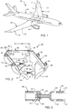
- FIG. 1 provides a perspective view of an aircraft 10.
- the embodiments of this disclosure relate to fasteners used to secure components of the aircraft 10 together, and more specifically to the encapsulation, covering, embedding or encasing of such fasteners in an insulating sealant.
- the disclosed embodiments may be employed to form enclosures for surrounding other types of fasteners disposed in a confined space that need to be covered, encapsulated, encased or embedded in a sealant.
- the aircraft 10 includes wings 11, 12 disposed on either side of and connected to a central wing box 13 that extends through the fuselage 14 of the aircraft 10.
- the wings 11, 12 connect to the fuselage 14 and to the central wing box 13 at the side of body joints 15, 16 respectively.
- the wings 11, 12 each include outer skins, including upper skins 17, 18 and lower skins 22, 23 respectively.
- fastener part of a fastener or portion of a fastener refer to the fasteners that connect the wing skins 17, 18, 22, 23 to the fuselage 14 or to a connecting structure such as a side of body chord 25 ( FIGS. 5-6 ) and further that extend at least partially into spaces provided in the wings 11, 12 that may serve as fuel tanks.
- the sealant containment assemblies and methods of embedding fasteners disclosed herein are not limited to aircraft applications, but are applicable to other situations where fasteners or portions of fasteners are disposed within confined spaces that need to be embedded, covered or sealed, with or without the need for electrical insulation.
- any fasteners used to connect the uppers skins 17, 18 or lower skins 22, 23 to the central wing box 13 and/or fuselage 14 via a side of body chord 25 (or other structure) require encasement in an insulating sealant.
- the insulating sealant prevents an electrical discharge in the event of a lightning strike to the aircraft 10.
- various types of fasteners 27 secure the lower skin 22 of the wing 11 to the first plate 28 of the side of body chord 25.
- the side of body chord 25 also includes a second plate 29 that connects to the stringer 24 but not by fasteners that pass through the upper skin 17 or lower skin 22.
- fasteners 27 that pass through the upper skins 17, 18 or lower skins 22, 23 and at least partially into confined spaces between the upper skin 17 and lower skin 22 or between the upper skin 18 and lower skin 23 need to be encased or encapsulated in insulating sealant to prevent an electrical discharge in the event of a lightning strike to the aircraft 10.
- FIG. 2 illustrates one disclosed sealant containment assembly 40.
- the sealant containment assembly 40 in this disclosed embodiment, includes three molded parts although two-part assemblies are available as discussed below and are considered to be within the scope of this disclosure.
- the sealant containment assembly 40 encloses the fasteners 27 that extend through a first surface, such as the first plate 28 of the side of body chord 25 as illustrated in FIGS. 5-6 .
- the first surface or first plate 28 is spaced apart from an opposing second surface or second plate 29 and the first and second surfaces as represented by the first and second plates 28, 29 engage a structural member, such as the stringer 24.
- the sealant containment assembly 40 comprises a first containment member 41 that extends between the first and second surfaces or between the first and second plates 28, 29.
- the sealant containment assembly 40 also includes a second containment member 42 that also extends between the first and second surfaces or between the first and second plates 28, 29.
- the fasteners 27 or portions of the fasteners 27 that need to be encased or embedded in sealant are disposed between the first and second containment members 41, 42.
- the first and second containment members 41, 42 each comprise structure-engaging ends 43, 44 respectively for engaging the structural member which, in the illustrated embodiment, is the stringer 24 as shown in FIG. 5 .
- the first and second containment members 41, 42 also include enclosure ends 46, 47 for coupling the first and second containment members 41, 42 together with the fasteners 27 disposed between the structural member or stringer 24 and the enclosure ends 46, 47.
- the enclosure ends 46, 47 of the first and second containment members 41, 42 are coupled together by an alignment member 48, which will be discussed in greater detail below in connection with FIG. 4 .
- the enclosure ends 46, 47 couple together more directly thereby enabling a two-piece assembly as opposed to the illustrated three-piece sealant containment assembly 40 of FIGS. 2-6 .
- the sealant containment assembly 40 encloses the fasteners 27 ( FIG. 6 ) within a confined space 51 ( FIG. 6 ) defined by the first and second containment members 41, 42, the first and second plates 28, 29 (or first and second surfaces), the structural member or stringer 24 and the connected enclosure ends 46, 47 which, in the illustrated embodiment, are coupled together by the alignment member 48.
- At least one of the first and second containment members 41, 42 include at least one injection port 52-55 disposed outside of the confined space 51 and that is in communication with at least one distribution passageway 56-59 disposed inside the confined space 51.
- the at least one distribution passageway 56-59 comprises at least one distribution port 61 ( FIG. 3 ) for distributing sealant within the confined space 51.
- both the first and second containment members 41, 42 include injection ports 52-53 and 54-55 respectively that are disposed outside of the confined space 51 and that are in communication with the distribution passageways 56-57 and 58-59 respectively, each of which include at least one distribution port 61, and each of which are disposed inside the confined space 51.
- the distribution passageways 56, 57 of the first containment member 41 connect to the distribution passageways 58-59 of the second containment member 42.
- both sets of distribution passageways 56, 58 and 57, 59 may not be connected but only one set of distribution passageways 56, 58 or 57, 59 are connected.
- FIG. 3 illustrates the connection between the distribution passageways 56, 57 of the first containment member 41 and the distribution passageways 58, 59 of the second containment member 42 respectively.
- the distribution passageways 56, 58 are connected together by a male/female connection such as the employment of a female end opening 62 that receives a barbed distal end 63 of a tube 64 that extends outward from the distribution passageway 58.
- the tube 64 may include a flange 65 as a stop.
- This disclosure is not limited to the male/female connection illustrated in FIGS. 2-3 .
- Other snap-fit-type, interlock-type, frictional-fit-type, etc. connections are available and will be apparent to those skilled in the art.
- the alignment member 48 includes a first end 71 that forms a groove 72 while the enclosure end 46 of the first containment member 41 ( FIG. 2 ) forms a tongue thereby providing a tongue-in-groove connection between the first end 71 of the alignment member 48 and the enclosure end 46 of the first containment member 41.
- the alignment member 48 as shown in FIG. 4 includes a second end 73 that similarly forms a groove 74 while the enclosure end 47 ( FIG. 2 ) of the second containment member 42 forms a tongue for a tongue-in-groove connection between the second end 73 of the alignment member 48 and the enclosure end 47 of the second containment member 42.
- the alignment member 48 connects to the first and second containment members 41, 42 with male/female connectors. More specifically, the alignment member 48 comprises an inner wall 75 ( FIG. 4 ) that faces the confined space 51 ( FIG. 6 ). The inner wall 75 connects to a rod 76 having oppositely directed or opposing barbed ends 77.
- the first and second containment members 41, 42 also each comprise an inner wall 81, 82 respectively that each connect to a socket 78 extending outward from its respective inner wall 81, 82. Each socket 78 receives one of the barbed ends 77 of the rod 76 ( FIG. 4 ) to connect the alignment member 48 to the first and second containment members 41, 42.
- the sealant containment assembly 40 provides an enclosure for containing sealant for encasing, embedding or encapsulating fasteners 27 disposed in a confined space 51, such as fasteners 27 used to secure a wing 11, 12 to a fuselage 14 of an aircraft 10.
- the fasteners 27 are disposed between two surfaces or two plates 28, 29 disposed inside one of the wings 11, 12 and between a structural member, such as a stringer 24 of one of the wings 11, 12 and the fuselage 14 of the aircraft 10.
- the sealant containment assembly 40 comprises a first containment member 41 that extends between the two surfaces or plates 28, 29 and a second containment member 42 that extends between the two surfaces or plates 28, 29 with the fasteners 27 disposed between the first and second containment members 41, 42.
- the first and second containment members 41, 42 each comprise structure-engaging ends 43, 44 for engaging the structural member or stringer 24 and enclosure ends 46, 47 that are connected or coupled together by an alignment member 48 that extends between the two surfaces or two plates 28, 29 with the fasteners 27 disposed between the structural member or stringer 24 and the alignment member 48.
- the sealant containment assembly 40 encloses the fasteners 27 within a confined space 51 ( FIG.
- first and second containment members 41, 42 defined by the first and second containment members 41, 42, the first and second surfaces or plates 28, 29, the structural member or stringer 24 and the alignment member 48.
- At least one of the first and second containment members 41, 42 comprises at least one injection port 52-55 disposed outside of the confined space 51 and that is in connection with at least one distribution passageway 56-59 that comprises at least one distribution port 61 disposed inside the confined space 51.
- the distribution passageways 56, 58 and 57, 59 may be connected using a variety of mechanisms, one of which is the male/female connection illustrated in FIG. 3 .
- the first end 71 and the second end 73 of the alignment member 48 may form a tongue-in-groove connection with the enclosure ends 46, 47 of the first and second containment members 41, 42 respectively.
- additional male/female connections between the alignment member 48 and the first and second containment members 41, 42 are optionally provided.
- a rod 76 with opposing barbed ends 77 mounted to the inner wall 75 of the alignment member 48 connects with sockets 78 disposed at the enclosure ends 46, 47 of the first and second containment members 41, 42 respectively.
- the injection ports 52-55 facilitate the injection sealant into the confined space 51 when the sealant containment assembly 40 is installed as illustrated in FIG. 5 .
- one or more gaps may be provided between the first and second containment members 41, 42 and one of the plates 28, 29 or between the alignment member 48 and one of the plates 28, 29.
- Such a gap like the gap 85 shown in FIG. 5 also provides a visual indication to the operator when the confined space 51 is filled with the insulating sealant.
- the fasteners 27 may be used to secure the skins 17, 18, 22, 23 of an aircraft 10 to a side of body chord 25 of an aircraft 10.
- the side of body chord 25 may include a first plate 28 and a second plate 29 that extend outward from a wall 86.
- the fasteners 27 connect the skin 22 to the first plate 28 as shown in FIGS. 5-6 with portions of the fasteners 27 disposed between the two plates 28, 29 and between the wall 86 of the side of body chord 25 and the structural member or stringer 24 of one of the wings 11, 12.
- the method comprises providing a first containment member 41 configured to extend between the first and second plates 28, 29 and providing a second containment member 42 configured to extend between the first and second plates 28, 29.
- the first and second containment members 41, 42 each comprise structure-engaging ends 43, 44 for engaging the structural member or stringer 24 of one the wings 11 or 12.
- the first and second containment members 41, 42 also each include enclosure ends 46, 47 respectively for connecting the first and second containment members 41, 42 together in a spaced-apart relationship as illustrated in FIGS. 2 and 5 .
- At least one of the first and second containment members 41, 42 comprises at least one injection port 52-55 that is in communication with at least one distribution passageway 56-59 that comprises at least one distribution port 61.
- the method further includes providing an alignment member 48 configured to extend between the first and second plates 28, 29 and further configured to align and connect the enclosure ends 46, 47 of the first and second containment members 41, 42.
- the method further includes connecting the first and second containment members 41, 42 to the alignment member 48 and engaging the structure-engaging ends 43, 44 of the first and second containment members 41, 42 with the structural member or stringer 24 to provide a confined space 51 between the first and second containment members 41, 42, between the first and second plates 28, 29 and between the structural member or stringer 24 and the alignment member 48.
- the method comprises injecting sealant into the at least one injection port 52-55 and out through the at least one distribution port 61 and into the confined space 51.
- the first and second containment members 41, 42 each comprise at least one injection port 52-55 disposed outside of the confined space 51 that is in communication with at least one distribution passageway 56-59 that comprises at least one distribution port 61 disposed inside the confined space 51.
- Such a method further comprises connecting the at least one distribution passageway 56, 57 of the first containment member 41 to the at least one distribution passageway 58, 59 of the second containment member 42.
- first and second containment members 41, 42 and the alignment member 48 include 3D printing or additive manufacturing. Because stringer joints are highly customized based on geometry and loads, the use of 3D printing or additive manufacturing allows the seal containment assembly 40 to be custom fit without the need to design and construct special tooling.
- Potential 3D printing or additive manufacturing techniques include, but are not limited to selective laser sintering (SLS) and fused deposition modelling (FDM).
- Suitable materials for forming first and second containment members 41, 42 and the alignment member 48 include various thermoplastics. In one or more embodiments, one suitable thermoplastic is PEKK (polyetherketoneketone).
- PEKK is particularly suitable for applications where the sealant containment assembly 40 is disposed within a fuel tank of an aircraft 10 because PEKK is compatible with jet fuel.
- manufacturers may employ other polymers or thermoplastics, depending upon the application, as will be apparent to those skilled in the art.
Landscapes
- Engineering & Computer Science (AREA)
- Aviation & Aerospace Engineering (AREA)
- Manufacturing & Machinery (AREA)
- Mechanical Engineering (AREA)
- General Engineering & Computer Science (AREA)
- Transportation (AREA)
- Connection Of Plates (AREA)
- Insulating Bodies (AREA)
Abstract
Description
- This disclosure relates to apparatuses and methods for embedding, encasing, encapsulating or covering fasteners in sealant, wherein the fasteners are disposed within a confined space.
- A typical aircraft wing assembly includes a central wing box and wings cantilevered from opposing sides of the wing box by "side of body joints." The wings typically include interior spaces that serve as fuel tanks. Some of the metal fasteners that connect the outer skin of the wings to the central wing box or to the side of body joints also extend into the fuel tanks. To prevent an electrical discharge within such a fuel tank in the case of a lightning strike against the outer skin, aircraft manufacturers embed the portions of the fasteners that extend from the skin into the tank in an electrically insulating material or insulating sealant. However, because of the confined space in which the fasteners are disposed, embedding the portions of such fasteners that extend into the fuel tanks is problematic, labor intensive and often requires filling large portions of the side of body joints with insulating sealant, resulting in substantial added weight and increased fuel consumption.
- Further, to reduce weight, composite materials are replacing metal as the material of construction of various aircraft components and structures, including the outer skin. Often, raw or uncoated edges of composite structures may be disposed in a confined space used to accommodate fuel. Because composite materials are conductive, any such raw edges also require insulation with a sealant, which is problematic because of the confined space.
- Accordingly, a need exists for an improved device and method for embedding, covering, encasing or encapsulating fasteners, portions of fasteners and other structural elements that extend into confined spaces. This need applies to the aircraft industry and other industries as well.
- In one disclosed embodiment, a sealant containment assembly encloses fasteners that extend through a first surface. The first surface is spaced-apart from an opposing second surface and the first and second surfaces engage a structural member. The sealant containment assembly comprises a first containment member that extends between the first and second surfaces and a second containment member that also extends between the first and second surfaces with the fasteners disposed between the first and second containment members. The first and second containment members each comprise a structure-engaging end for engaging the structural member. The first and second containment members also each comprise an enclosure end that couples the first and second containment members together with the fasteners also disposed between the structural member and the connected enclosure ends. As a result, the sealant containment assembly encloses the fasteners within a confined space defined by the first and second containment members, the first and second surfaces, the structural member and the coupled enclosure ends. At least one of the first and second containment members includes at least one injection port disposed outside of the confined space that is in communication with at least one distribution passageway disposed inside the confined space. The distribution passageway comprises at least one distribution port for distributing sealant within the confined space.
- Another disclosed embodiment is a sealant containment assembly for fasteners used to secure a wing to a fuselage of an aircraft. The fasteners are disposed between two surfaces disposed inside the wing and between a structural member of the wing and a fuselage of the aircraft. The sealant containment assembly comprises a first containment member that extends between the two surfaces and a second containment member that extends between the two surfaces with the fasteners disposed between the first and second containment members. The first and second containment members each comprise structure-engaging ends for engaging the structural member and enclosure ends coupled by an alignment member that extends between the two surfaces with the fasteners also disposed between the structural member and the alignment member. As a result, the sealant containment assembly encloses the fasteners within a confined space defined by the first and second containment members, the first and second surfaces, the structural member and the alignment member. Further, at least one of the first and second containment members includes at least one injection port disposed outside of the confined space and that is in communication with at least one distribution passageway disposed inside the confined space. The distribution passageway comprises at least one distribution port for distributing sealant within the confined space.
- Another disclosed embodiment includes a method for encasing or embedding fasteners in sealant. The fasteners secure a skin of a wing of an aircraft to a side of body chord of the aircraft. The side of body chord includes a first plate and a second plate that extend outward from a wall. The fasteners connect the skin to the first plate with portions of the fasteners disposed between the two plates and between the wall of the side of body chord and a structural member of the wing. The method comprises providing a first containment member configured to extend between the first and second plates and a second containment member also configured to extend between the first and second plates. The first and second containment members each include structure-engaging ends for engaging the structural member of the wing and enclosure ends for connecting the first and second containment members together in a spaced-apart relationship. At least one of the first and second containment members include at least one injection port that is in communication with at least one distribution passageway that comprises at least one distribution port. The method further includes providing an alignment member configured to extend between the first and second plates and further configured to align and connect the enclosure ends of the first and second containment members together. The method further includes connecting the first and second containment members to the alignment member and engaging the structure-engaging ends of the first and second containment members with the structural member to provide a confined space between the first and second containment members, between the first and second plates and between the structural member and the alignment member. Further, the method comprises injecting sealant into the at least one injection port, through the distribution passageway, out through the at least one distribution port and into the confined space.
- Other advantages and features will be apparent from the following detailed description when read in conjunction with the attached drawings.
- For a more complete understanding of the disclosed methods and apparatuses, reference should be made to the embodiment illustrated in greater detail in the accompanying drawings, wherein:
-
FIG. 1 is a perspective view of an aircraft. -
FIG. 2 is a perspective view of one disclosed sealant containment assembly. -
FIG. 3 is a partial sectional view taken substantially along line 3-3 ofFIG. 2 and illustrating the male/female connection between two distribution passageways of two sealant containment members. -
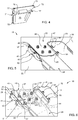
FIG. 4 is a perspective view of the alignment member of the sealant containment assembly shown inFIG. 2 . -
FIG. 5 is a perspective view illustrating the sealant containment assembly ofFIG. 2 installed between two (upper and lower) plates of a side of body chord and between a stringer and vertically-oriented wall of the side of body chord thereby enclosing fasteners used to secure the skin of the wing of the aircraft to the side of body chord. -
FIG. 6 is a perspective and exploded view of the sealant containment assembly ofFIGS. 2 and5 that illustrates the ease of which the sealant containment assembly may be installed between the side of body chord and the stringer as illustrated inFIG. 5 . - The drawings are not necessarily to scale and may illustrate the disclosed embodiment schematically, diagrammatically and/or in partial views. In certain instances, the drawings may omit details which are not necessary for an understanding of the disclosed methods and apparatuses or which render other details difficult to perceive. This disclosure is not limited to the particular embodiment illustrated herein.
-
FIG. 1 provides a perspective view of anaircraft 10. The embodiments of this disclosure relate to fasteners used to secure components of theaircraft 10 together, and more specifically to the encapsulation, covering, embedding or encasing of such fasteners in an insulating sealant. However, the disclosed embodiments may be employed to form enclosures for surrounding other types of fasteners disposed in a confined space that need to be covered, encapsulated, encased or embedded in a sealant. - The
aircraft 10 includeswings central wing box 13 that extends through thefuselage 14 of theaircraft 10. Thewings fuselage 14 and to thecentral wing box 13 at the side ofbody joints wings upper skins lower skins - While various spatial and directional terms, such as top, bottom, lower, upper, mid, lateral, horizontal, vertical, front, rear and the like may be used to describe embodiments disclosed herein, it is understood that such terms are used with respect to the orientation shown in the drawings. The orientations may be inverted, rotated or otherwise changed such that an upper portion becomes a lower portion and vice versa, and horizontal becomes vertical and the like.
- Further, for purposes of this disclosure, the terms fastener, part of a fastener or portion of a fastener refer to the fasteners that connect the
wing skins fuselage 14 or to a connecting structure such as a side of body chord 25 (FIGS. 5-6 ) and further that extend at least partially into spaces provided in thewings - Various fasteners secure the
upper skins lower skins central wing box 13 andfuselage 14 at the side ofbody joints upper skins lower skins wings stringer 24 and side ofbody chord 25 as shown inFIGS. 5-6 , the spaces between theupper skins lower skins wings uppers skins lower skins central wing box 13 and/orfuselage 14 via a side of body chord 25 (or other structure) require encasement in an insulating sealant. The insulating sealant prevents an electrical discharge in the event of a lightning strike to theaircraft 10. - Specifically, as shown in
FIG. 6 , various types offasteners 27 secure thelower skin 22 of thewing 11 to thefirst plate 28 of the side ofbody chord 25. The side ofbody chord 25 also includes asecond plate 29 that connects to thestringer 24 but not by fasteners that pass through theupper skin 17 orlower skin 22. Thus, only thefasteners 27 that pass through theupper skins lower skins upper skin 17 andlower skin 22 or between theupper skin 18 andlower skin 23 need to be encased or encapsulated in insulating sealant to prevent an electrical discharge in the event of a lightning strike to theaircraft 10. -
FIG. 2 illustrates one disclosedsealant containment assembly 40. Thesealant containment assembly 40, in this disclosed embodiment, includes three molded parts although two-part assemblies are available as discussed below and are considered to be within the scope of this disclosure. Thesealant containment assembly 40 encloses thefasteners 27 that extend through a first surface, such as thefirst plate 28 of the side ofbody chord 25 as illustrated inFIGS. 5-6 . The first surface orfirst plate 28 is spaced apart from an opposing second surface orsecond plate 29 and the first and second surfaces as represented by the first andsecond plates stringer 24. - Referring to
FIGS. 2 and5 , thesealant containment assembly 40 comprises afirst containment member 41 that extends between the first and second surfaces or between the first andsecond plates sealant containment assembly 40 also includes asecond containment member 42 that also extends between the first and second surfaces or between the first andsecond plates FIG. 6 , thefasteners 27 or portions of thefasteners 27 that need to be encased or embedded in sealant are disposed between the first andsecond containment members - The first and
second containment members stringer 24 as shown inFIG. 5 . The first andsecond containment members second containment members fasteners 27 disposed between the structural member orstringer 24 and the enclosure ends 46, 47. In the embodiment illustrated inFIGS. 2 and6 , the enclosure ends 46, 47 of the first andsecond containment members alignment member 48, which will be discussed in greater detail below in connection withFIG. 4 . However, the enclosure ends 46, 47, in other embodiments, couple together more directly thereby enabling a two-piece assembly as opposed to the illustrated three-piecesealant containment assembly 40 ofFIGS. 2-6 . As illustrated inFIGS. 5-6 , thesealant containment assembly 40 encloses the fasteners 27 (FIG. 6 ) within a confined space 51 (FIG. 6 ) defined by the first andsecond containment members second plates 28, 29 (or first and second surfaces), the structural member orstringer 24 and the connected enclosure ends 46, 47 which, in the illustrated embodiment, are coupled together by thealignment member 48. - In the illustrated embodiment, at least one of the first and
second containment members space 51 and that is in communication with at least one distribution passageway 56-59 disposed inside the confinedspace 51. The at least one distribution passageway 56-59 comprises at least one distribution port 61 (FIG. 3 ) for distributing sealant within the confinedspace 51. In the illustrated embodiment, both the first andsecond containment members space 51 and that are in communication with the distribution passageways 56-57 and 58-59 respectively, each of which include at least onedistribution port 61, and each of which are disposed inside the confinedspace 51. Also, in the illustrated embodiment, thedistribution passageways first containment member 41 connect to the distribution passageways 58-59 of thesecond containment member 42. In other embodiments, both sets ofdistribution passageways distribution passageways FIG. 3 illustrates the connection between thedistribution passageways first containment member 41 and thedistribution passageways second containment member 42 respectively. InFIG. 3 , thedistribution passageways distal end 63 of atube 64 that extends outward from thedistribution passageway 58. Thetube 64 may include aflange 65 as a stop. This disclosure is not limited to the male/female connection illustrated inFIGS. 2-3 . Other snap-fit-type, interlock-type, frictional-fit-type, etc. connections are available and will be apparent to those skilled in the art. - In a further refinement, shown in
FIG. 4 , thealignment member 48 includes afirst end 71 that forms agroove 72 while theenclosure end 46 of the first containment member 41 (FIG. 2 ) forms a tongue thereby providing a tongue-in-groove connection between thefirst end 71 of thealignment member 48 and theenclosure end 46 of thefirst containment member 41. Similarly, thealignment member 48 as shown inFIG. 4 includes asecond end 73 that similarly forms agroove 74 while the enclosure end 47 (FIG. 2 ) of thesecond containment member 42 forms a tongue for a tongue-in-groove connection between thesecond end 73 of thealignment member 48 and theenclosure end 47 of thesecond containment member 42. In an additional or alternative refinement, thealignment member 48 connects to the first andsecond containment members alignment member 48 comprises an inner wall 75 (FIG. 4 ) that faces the confined space 51 (FIG. 6 ). Theinner wall 75 connects to arod 76 having oppositely directed or opposing barbed ends 77. Referring back toFIG. 2 , the first andsecond containment members inner wall socket 78 extending outward from its respectiveinner wall socket 78 receives one of the barbed ends 77 of the rod 76 (FIG. 4 ) to connect thealignment member 48 to the first andsecond containment members - Thus, the
sealant containment assembly 40 provides an enclosure for containing sealant for encasing, embedding or encapsulatingfasteners 27 disposed in a confinedspace 51, such asfasteners 27 used to secure awing fuselage 14 of anaircraft 10. In such an application, thefasteners 27 are disposed between two surfaces or twoplates wings stringer 24 of one of thewings fuselage 14 of theaircraft 10. Thesealant containment assembly 40 comprises afirst containment member 41 that extends between the two surfaces orplates second containment member 42 that extends between the two surfaces orplates fasteners 27 disposed between the first andsecond containment members second containment members stringer 24 and enclosure ends 46, 47 that are connected or coupled together by analignment member 48 that extends between the two surfaces or twoplates fasteners 27 disposed between the structural member orstringer 24 and thealignment member 48. As a result, thesealant containment assembly 40 encloses thefasteners 27 within a confined space 51 (FIG. 6 ) defined by the first andsecond containment members plates stringer 24 and thealignment member 48. At least one of the first andsecond containment members space 51 and that is in connection with at least one distribution passageway 56-59 that comprises at least onedistribution port 61 disposed inside the confinedspace 51. As noted above, thedistribution passageways FIG. 3 . Thefirst end 71 and thesecond end 73 of thealignment member 48 may form a tongue-in-groove connection with the enclosure ends 46, 47 of the first andsecond containment members FIGS. 2 and4 , additional male/female connections between thealignment member 48 and the first andsecond containment members rod 76 with opposing barbed ends 77 mounted to theinner wall 75 of thealignment member 48 connects withsockets 78 disposed at the enclosure ends 46, 47 of the first andsecond containment members - The injection ports 52-55 facilitate the injection sealant into the confined
space 51 when thesealant containment assembly 40 is installed as illustrated inFIG. 5 . To vent the confinedspace 51 during the injection of the sealant, one or more gaps may be provided between the first andsecond containment members plates alignment member 48 and one of theplates gap 85 shown inFIG. 5 also provides a visual indication to the operator when the confinedspace 51 is filled with the insulating sealant. - Various methods for encasing or embedding
fasteners 27 in sealant are disclosed. Thefasteners 27 may be used to secure theskins aircraft 10 to a side ofbody chord 25 of anaircraft 10. The side ofbody chord 25 may include afirst plate 28 and asecond plate 29 that extend outward from awall 86. Thefasteners 27 connect theskin 22 to thefirst plate 28 as shown inFIGS. 5-6 with portions of thefasteners 27 disposed between the twoplates wall 86 of the side ofbody chord 25 and the structural member orstringer 24 of one of thewings first containment member 41 configured to extend between the first andsecond plates second containment member 42 configured to extend between the first andsecond plates second containment members stringer 24 of one thewings second containment members second containment members FIGS. 2 and5 . At least one of the first andsecond containment members distribution port 61. The method further includes providing analignment member 48 configured to extend between the first andsecond plates second containment members second containment members alignment member 48 and engaging the structure-engaging ends 43, 44 of the first andsecond containment members stringer 24 to provide a confinedspace 51 between the first andsecond containment members second plates stringer 24 and thealignment member 48. Further, the method comprises injecting sealant into the at least one injection port 52-55 and out through the at least onedistribution port 61 and into the confinedspace 51. As shown in the drawings, the first andsecond containment members space 51 that is in communication with at least one distribution passageway 56-59 that comprises at least onedistribution port 61 disposed inside the confinedspace 51. Such a method further comprises connecting the at least onedistribution passageway first containment member 41 to the at least onedistribution passageway second containment member 42. - Techniques for forming the first and
second containment members alignment member 48 include 3D printing or additive manufacturing. Because stringer joints are highly customized based on geometry and loads, the use of 3D printing or additive manufacturing allows theseal containment assembly 40 to be custom fit without the need to design and construct special tooling. Potential 3D printing or additive manufacturing techniques include, but are not limited to selective laser sintering (SLS) and fused deposition modelling (FDM). Suitable materials for forming first andsecond containment members alignment member 48 include various thermoplastics. In one or more embodiments, one suitable thermoplastic is PEKK (polyetherketoneketone). PEKK is particularly suitable for applications where thesealant containment assembly 40 is disposed within a fuel tank of anaircraft 10 because PEKK is compatible with jet fuel. However, manufacturers may employ other polymers or thermoplastics, depending upon the application, as will be apparent to those skilled in the art. - Further, the disclosure comprises embodiments according to the following clauses:
- Clause 1. A sealant containment assembly for enclosing fasteners that extend through a first surface, the first surface being spaced apart from an opposing second surface and the first and second surfaces engaging a structural member, the sealant containment assembly comprising:
- a first containment member that extends between the first and second surfaces and a second containment member that extends between the first and second surfaces with the fasteners disposed between the first and second containment members,
- the first and second containment members each comprising structure-engaging ends for engaging the structural member and enclosure ends that connect the first and second containment members together with the fasteners disposed between the structural member and the enclosure ends thereby enclosing the fasteners within a confined space defined by the first and second containment members, the first and second surfaces, the structural member and the enclosure ends,
- at least one of the first and second containment members including at least one injection port disposed outside of the confined space that is in communication with at least one distribution passageway disposed inside the confined space, the at least one distribution passageway comprising at least one distribution port for distributing sealant within the confined space.
- Clause 2. The sealant containment assembly of Clause 1 wherein each of the first and second containment members include at least one injection port disposed outside of the confined space that is in communication with at least one distribution passageway comprising at least one distribution port disposed inside the confined space.
- Clause 3. The sealant containment assembly of Clause 2 wherein the distribution passageway of the first containment member connects to the distribution passageway of the second containment member.
- Clause 4. The sealant containment assembly of Clause 3 wherein the distribution passageways of the first and second containment members are connected by a male/female connection.
- Clause 5. The sealant containment assembly of Clause 1 wherein the enclosure ends of the first and second containment members are connected by an alignment member that extends between the first and second surfaces.
- Clause 6. The sealant containment assembly of Clause 5 wherein the alignment member includes a first end that forms a tongue in groove connection with the enclosure end of the first containment member and the alignment member includes a second end that forms a tongue in groove connection with the enclosure end of the second containment member.
- Clause 7. The sealant containment assembly of Clause 5 wherein the alignment member is connected to the first and second containment members with male/female connectors.
- Clause 8. The sealant containment assembly of Clause 1 further comprising a gap disposed between at least part of one of the first and second containment members and at least one of the first and second surfaces to vent the confined space during injection of sealant through the at least one injection port.
- Clause 9. The sealant containment assembly of Clause 5 wherein the alignment member comprises an inner wall that faces the confined space and that connects to a rod having opposing barbed ends, and the first and second containment members each comprise an inner wall having a socket extending outward from the inner wall, each socket receiving one of the barbed ends of the rod to connect the alignment member to the first and second containment members.
-
Clause 10. A sealant containment assembly for fasteners used to secure a wing to a fuselage of an aircraft, wherein the fasteners are disposed between two surfaces disposed inside the wing and between a structural member of the wing and the fuselage of the aircraft, the sealant containment assembly comprising:- a first containment member that extends between the two surfaces and a second containment member that extends between the two surfaces with the fasteners disposed between the first and second containment members,
- the first and second containment members each comprising structure-engaging ends for engaging the structural member and enclosure ends that are connected together by an alignment member that extends between the two surfaces with the fasteners disposed between the structural member and the alignment member thereby enclosing the fasteners within a confined space defined by the first and second containment members, defined by the first and second surfaces and defined by the structural member and the alignment member,
- at least one of the first and second containment members comprises at least one injection port disposed outside of the confined space that is in communication with at least one distribution passageway disposed inside the confined space, the distribution passageway comprising at least one distribution port for distributing sealant within the confined space.
-
Clause 11. The sealant containment assembly ofClause 10 wherein each of the first and second containment members include at least one injection port disposed outside of the confined space that is in communication with at least one distribution passageway comprising at least one distribution port disposed inside the confined space. -
Clause 12. The sealant containment assembly ofClause 11 wherein the distribution passageway of the first containment member connects to the distribution passageway of the second containment member. -
Clause 13. The sealant containment assembly ofClause 11 wherein the distribution passageways of the first and second containment members are connected by a male/female connection. -
Clause 14. The sealant containment assembly ofClause 10 wherein the alignment member includes a first end that forms a tongue in groove connection with the enclosure end of the first containment member and the alignment member includes a second end that forms a tongue in groove connection with the enclosure end of the second containment member. -
Clause 15. The sealant containment assembly ofClause 10 wherein the alignment member is connected to the first and second containment members with male/female connectors. -
Clause 16. The sealant enclosure system ofClause 10 further comprising a gap disposed between at least part of one of the first and second containment members and at least one of the first and second surfaces to vent the confined space during injection of sealant through the at least one injection port. -
Clause 17. The sealant enclosure system ofClause 10 wherein the alignment member comprises an inner wall that faces the confined space and that connects to a rod having opposing barbed ends, and the first and second containment members each comprise an inner wall having a socket extending outward from the inner wall, each socket receiving one of the barbed ends of the rod to connect the alignment member to the first and second containment members. -
Clause 18. A method for embedding fasteners in sealant wherein the fasteners are used to secure a skin of a wing of an aircraft to a side of body chord of the aircraft, the side of body chord including a first plate and a second plate that extend outward from a wall, the fasteners connecting the skin to the first plate with portions of the fasteners disposed between the two plates and between the wall of the side of body chord and a structural member of the wing, the method comprising:- providing a first containment member configured to extend between the first and second plates and a second containment member configured to extend between first and second plates, the first and second containment members each comprising structure-engaging ends for engaging the structural member of the wing and enclosure ends for connecting the first and second containment members together in a spaced-apart relationship, at least one of the first and second containment members comprising at least one injection port that is in communication with at least one distribution passageway that comprises at least one distribution port;
- providing an alignment member configured to extend between the first and second plates and further configured to align and connect the enclosure ends of the first and second containment members together;
- connecting the first and second containment members to the alignment member and engaging the structure-engaging ends of the first and second containment members with the structural member to provide a confined space between the first and second containment members, between the first and second plates and between the structural member and the alignment member; and
- injecting sealant into the at least one injection port and out through the at least one distribution port and into the confined space.
- Clause 19. The method of
Clause 18 wherein each of the first and second containment members comprise at least one injection port disposed outside of the confined space that is in communication with at least one distribution passageway comprising at least one distribution port disposed inside the confined space, and the method further comprises
connecting the at least one distribution passageway of the first containment member to the at least one distribution passageway of the second containment member. - Clause 20. The method of
Clause 18 wherein the providing of first and second containment members and the providing of the alignment member comprises fabricating the first and second containment members and the alignment member using 3D printing. - While only certain embodiments have been set forth, alternatives and modifications will be apparent from the above description to those skilled in the art. Further, aspects of different embodiments may be combined or substituted with one another. These and other alternatives are considered equivalents and within the spirit and scope of this disclosure and the appended claims.
Claims (12)
- A sealant containment assembly (40) for enclosing fasteners (27) that extend through a first surface (28), the first surface being spaced apart from an opposing second surface (29) and the first and second surfaces engaging a structural member (24), the sealant containment assembly comprising:a first containment member (41) that extends between the first and second surfaces and a second containment member that extends between the first and second surfaces with the fasteners disposed between the first and second containment members,the first and second containment members each comprising structure-engaging ends (43, 44) for engaging the structural member and enclosure ends (46, 47) that connect the first and second containment members together with the fasteners disposed between the structural member and the enclosure ends thereby enclosing the fasteners within a confined space (51) defined by the first and second containment members, the first and second surfaces, the structural member and the enclosure ends,at least one of the first and second containment members including at least one injection port (52-55) disposed outside of the confined space that is in communication with at least one distribution passageway (56-59) disposed inside the confined space, the at least one distribution passageway comprising at least one distribution port (61) for distributing sealant within the confined space.
- The sealant containment assembly (40) of claim 1 wherein each of the first (41) and second containment members (42) include at least one injection port disposed outside of the confined space that is in communication with at least one distribution passageway comprising at least one distribution port disposed inside the confined space.
- The sealant containment assembly (40) of claim 2 wherein the distribution passageway (56-59) of the first containment member (41) connects to the distribution passageway of the second containment member (42).
- The sealant containment assembly (40) of any of claims 2-3 wherein the distribution passageways (56-59) of the first (41) and second containment members (42) are connected by a male/female connection (62, 63, 64).
- The sealant containment assembly (40) of any of claims 1-4 wherein the enclosure ends (46, 47) of the first (41) and second containment members (42) are connected by an alignment member (48) that extends between the first (28) and second surfaces (29).
- The sealant containment assembly (40) of claim 5 wherein the alignment member (48) includes a first end (71) that forms a tongue in groove connection with the enclosure end (46) of the first containment member (41) and the alignment member includes a second end (72) that forms a tongue in groove connection with the enclosure end (47) of the second containment member (42).
- The sealant containment assembly (40) of any of claims 5-6 wherein the alignment member (48) is connected to the first (41) and second containment members (42) with male/female connectors (62, 63, 64).
- The sealant containment assembly (40) of any of claims 1-7 further comprising a gap (85) disposed between at least part of one of the first (41) and second containment members (42) and at least one of the first (28) and second surfaces (29) to vent the confined space (51) during injection of sealant through the at least one injection port (52-55).
- The sealant containment assembly (40) of any of claims 5-8 wherein the alignment member (48) comprises an inner wall (75) that faces the confined space (51) and that connects to a rod (76) having opposing barbed ends (77), and the first (41) and second containment members (42) each comprise an inner wall (81, 82) having a socket (78) extending outward from the inner wall, each socket receiving one of the barbed ends of the rod to connect the alignment member to the first and second containment members.
- A method for embedding fasteners (27) in sealant wherein the fasteners are used to secure a skin (17, 18, 22, 23) of a wing (11, 12) of an aircraft (10) to a side of body chord (25) of the aircraft, the side of body chord including a first plate (28) and a second plate (29) that extend outward from a wall 86, the fasteners connecting the skin to the first plate with portions of the fasteners disposed between the two plates and between the wall of the side of body chord and a structural member (24) of the wing, the method comprising:providing a first containment member (41) configured to extend between the first and second plates and a second containment member (42) configured to extend between first and second plates, the first and second containment members each comprising structure-engaging ends (43, 44) for engaging the structural member of the wing and enclosure ends (46, 47) for connecting the first and second containment members together in a spaced-apart relationship, at least one of the first and second containment members comprising at least one injection port (52-55) that is in communication with at least one distribution passageway (56-59) that comprises at least one distribution port (61);providing an alignment member (48) configured to extend between the first and second plates and further configured to align and connect the enclosure ends of the first and second containment members together;connecting the first and second containment members to the alignment member and engaging the structure-engaging ends of the first and second containment members with the structural member to provide a confined space (51) between the first and second containment members, between the first and second plates and between the structural member and the alignment member; andinjecting sealant into the at least one injection port and out through the at least one distribution port and into the confined space.
- The method of claim 10 wherein each of the first (41) and second containment members (42) comprise at least one injection port (52-55) disposed outside of the confined space (51) that is in communication with at least one distribution passageway (56-59) comprising at least one distribution port (61) disposed inside the confined space, and the method further comprises
connecting the at least one distribution passageway of the first containment member to the at least one distribution passageway of the second containment member. - The method of any of claims 10-11 wherein the providing of first (41) and second containment members (42) and the providing of the alignment member (48) comprises fabricating the first and second containment members and the alignment member using 3D printing.
Applications Claiming Priority (1)
| Application Number | Priority Date | Filing Date | Title |
|---|---|---|---|
| US15/142,465 US10087970B2 (en) | 2016-04-29 | 2016-04-29 | Sealant Containment Assembly |
Publications (2)
| Publication Number | Publication Date |
|---|---|
| EP3239054A1 true EP3239054A1 (en) | 2017-11-01 |
| EP3239054B1 EP3239054B1 (en) | 2020-06-10 |
Family
ID=58016580
Family Applications (1)
| Application Number | Title | Priority Date | Filing Date |
|---|---|---|---|
| EP17155364.7A Active EP3239054B1 (en) | 2016-04-29 | 2017-02-09 | Sealant containment assembly |
Country Status (5)
| Country | Link |
|---|---|
| US (1) | US10087970B2 (en) |
| EP (1) | EP3239054B1 (en) |
| JP (1) | JP6904763B2 (en) |
| CN (1) | CN107336843B (en) |
| ES (1) | ES2803323T3 (en) |
Families Citing this family (1)
| Publication number | Priority date | Publication date | Assignee | Title |
|---|---|---|---|---|
| US11174042B2 (en) * | 2018-10-09 | 2021-11-16 | The Boeing Company | Wing join system and method for a wing assembly |
Citations (4)
| Publication number | Priority date | Publication date | Assignee | Title |
|---|---|---|---|---|
| US3543719A (en) * | 1968-04-09 | 1970-12-01 | Lockheed Aircraft Corp | Sealant applying tool |
| US4404054A (en) * | 1980-09-22 | 1983-09-13 | The Boeing Company | Method for applying sealant between faying surfaces of aircraft wing structures |
| EP0181483A1 (en) * | 1984-10-15 | 1986-05-21 | Ltv Aerospace And Defense Company | Method and apparatus for applying a precision amount of sealant to exposed fasteners |
| US20140261994A1 (en) * | 2013-03-17 | 2014-09-18 | The Boeing Company | Seal molding system and method |
Family Cites Families (6)
| Publication number | Priority date | Publication date | Assignee | Title |
|---|---|---|---|---|
| US7837148B2 (en) | 2006-06-13 | 2010-11-23 | The Boeing Company | Composite wing-body joint |
| US7887009B2 (en) | 2007-12-05 | 2011-02-15 | The Boeing Company | Methods and systems for attaching aircraft wings to fuselages |
| FR2960852B1 (en) * | 2010-06-04 | 2013-04-12 | Dassault Aviat | AIRCRAFT STRUCTURAL ASSEMBLY AND ASSOCIATED ASSEMBLY METHOD |
| US8777158B2 (en) * | 2011-03-25 | 2014-07-15 | The Boeing Company | Joint sealing system |
| US8993097B2 (en) | 2011-10-10 | 2015-03-31 | The Boeing Company | Tapered height curved composite stringers and corresponding panels |
| US10479475B2 (en) | 2013-08-09 | 2019-11-19 | The Boeing Company | Composite stringer beam joint structure of an aircraft |
-
2016
- 2016-04-29 US US15/142,465 patent/US10087970B2/en active Active
-
2017
- 2017-02-09 ES ES17155364T patent/ES2803323T3/en active Active
- 2017-02-09 EP EP17155364.7A patent/EP3239054B1/en active Active
- 2017-03-27 CN CN201710186294.5A patent/CN107336843B/en active Active
- 2017-04-18 JP JP2017081810A patent/JP6904763B2/en active Active
Patent Citations (4)
| Publication number | Priority date | Publication date | Assignee | Title |
|---|---|---|---|---|
| US3543719A (en) * | 1968-04-09 | 1970-12-01 | Lockheed Aircraft Corp | Sealant applying tool |
| US4404054A (en) * | 1980-09-22 | 1983-09-13 | The Boeing Company | Method for applying sealant between faying surfaces of aircraft wing structures |
| EP0181483A1 (en) * | 1984-10-15 | 1986-05-21 | Ltv Aerospace And Defense Company | Method and apparatus for applying a precision amount of sealant to exposed fasteners |
| US20140261994A1 (en) * | 2013-03-17 | 2014-09-18 | The Boeing Company | Seal molding system and method |
Also Published As
| Publication number | Publication date |
|---|---|
| CN107336843B (en) | 2022-05-03 |
| ES2803323T3 (en) | 2021-01-26 |
| JP2018008677A (en) | 2018-01-18 |
| US20170314603A1 (en) | 2017-11-02 |
| CN107336843A (en) | 2017-11-10 |
| JP6904763B2 (en) | 2021-07-21 |
| EP3239054B1 (en) | 2020-06-10 |
| US10087970B2 (en) | 2018-10-02 |
Similar Documents
| Publication | Publication Date | Title |
|---|---|---|
| CN107298182B (en) | Retractable cover assembly for enclosing fasteners disposed in a confined space | |
| US9570838B2 (en) | Structure of highly waterproof connector for easy conduction between ground pin and body | |
| US20140227913A1 (en) | Electric Connector with a Lock to Retain a Terminal Within a Housing | |
| EP3654457B1 (en) | Electrical connector sealing system | |
| EP3324458B1 (en) | Battery cell assembly | |
| US20130090007A1 (en) | Terminal box for solar cell module | |
| JP2014164875A (en) | Terminal board and electronic apparatus including the same | |
| EP3239054B1 (en) | Sealant containment assembly | |
| DE102019104655A1 (en) | High current wiring for charging connectors and vehicle | |
| CN103477519A (en) | Sealing element and a sealing system for hollow sections | |
| JP2018116896A (en) | connector | |
| US10938164B2 (en) | Primary plugin, drawer and distribution panel for power distribution system | |
| DE202019100048U1 (en) | High-voltage bushing | |
| CN104638461A (en) | Connector | |
| DE102016219993A1 (en) | Battery module housing | |
| EP2109190A1 (en) | Basic insulating plug and method of manufacture | |
| CN207781725U (en) | Connecting terminal and battery pack for battery pack | |
| CN206293734U (en) | A kind of velocity sensor connector | |
| CN206412541U (en) | A kind of isolated wire rod waterproof construction and the electrical equipment with it | |
| CN113675426A (en) | A combined sealing structure for a fuel cell module | |
| DE202018104462U1 (en) | Electrical connector for electrical appliance | |
| KR102824497B1 (en) | Sealed cable connector, its manufacturing method and use | |
| CN208889896U (en) | Connection terminal and detachable connector | |
| CN208923473U (en) | A kind of integrated connector | |
| CN205985553U (en) | Staircase cable connector |
Legal Events
| Date | Code | Title | Description |
|---|---|---|---|
| PUAI | Public reference made under article 153(3) epc to a published international application that has entered the european phase |
Free format text: ORIGINAL CODE: 0009012 |
|
| STAA | Information on the status of an ep patent application or granted ep patent |
Free format text: STATUS: REQUEST FOR EXAMINATION WAS MADE |
|
| 17P | Request for examination filed |
Effective date: 20170209 |
|
| AK | Designated contracting states |
Kind code of ref document: A1 Designated state(s): AL AT BE BG CH CY CZ DE DK EE ES FI FR GB GR HR HU IE IS IT LI LT LU LV MC MK MT NL NO PL PT RO RS SE SI SK SM TR |
|
| AX | Request for extension of the european patent |
Extension state: BA ME |
|
| RBV | Designated contracting states (corrected) |
Designated state(s): AL AT BE BG CH CY CZ DE DK EE ES FI FR GB GR HR HU IE IS IT LI LT LU LV MC MK MT NL NO PL PT RO RS SE SI SK SM TR |
|
| STAA | Information on the status of an ep patent application or granted ep patent |
Free format text: STATUS: EXAMINATION IS IN PROGRESS |
|
| 17Q | First examination report despatched |
Effective date: 20190506 |
|
| GRAP | Despatch of communication of intention to grant a patent |
Free format text: ORIGINAL CODE: EPIDOSNIGR1 |
|
| STAA | Information on the status of an ep patent application or granted ep patent |
Free format text: STATUS: GRANT OF PATENT IS INTENDED |
|
| INTG | Intention to grant announced |
Effective date: 20200120 |
|
| GRAS | Grant fee paid |
Free format text: ORIGINAL CODE: EPIDOSNIGR3 |
|
| GRAA | (expected) grant |
Free format text: ORIGINAL CODE: 0009210 |
|
| STAA | Information on the status of an ep patent application or granted ep patent |
Free format text: STATUS: THE PATENT HAS BEEN GRANTED |
|
| AK | Designated contracting states |
Kind code of ref document: B1 Designated state(s): AL AT BE BG CH CY CZ DE DK EE ES FI FR GB GR HR HU IE IS IT LI LT LU LV MC MK MT NL NO PL PT RO RS SE SI SK SM TR |
|
| REG | Reference to a national code |
Ref country code: GB Ref legal event code: FG4D |
|
| REG | Reference to a national code |
Ref country code: AT Ref legal event code: REF Ref document number: 1278985 Country of ref document: AT Kind code of ref document: T Effective date: 20200615 Ref country code: CH Ref legal event code: EP |
|
| REG | Reference to a national code |
Ref country code: DE Ref legal event code: R096 Ref document number: 602017017859 Country of ref document: DE |
|
| REG | Reference to a national code |
Ref country code: IE Ref legal event code: FG4D |
|
| REG | Reference to a national code |
Ref country code: LT Ref legal event code: MG4D |
|
| PG25 | Lapsed in a contracting state [announced via postgrant information from national office to epo] |
Ref country code: FI Free format text: LAPSE BECAUSE OF FAILURE TO SUBMIT A TRANSLATION OF THE DESCRIPTION OR TO PAY THE FEE WITHIN THE PRESCRIBED TIME-LIMIT Effective date: 20200610 Ref country code: SE Free format text: LAPSE BECAUSE OF FAILURE TO SUBMIT A TRANSLATION OF THE DESCRIPTION OR TO PAY THE FEE WITHIN THE PRESCRIBED TIME-LIMIT Effective date: 20200610 Ref country code: LT Free format text: LAPSE BECAUSE OF FAILURE TO SUBMIT A TRANSLATION OF THE DESCRIPTION OR TO PAY THE FEE WITHIN THE PRESCRIBED TIME-LIMIT Effective date: 20200610 Ref country code: GR Free format text: LAPSE BECAUSE OF FAILURE TO SUBMIT A TRANSLATION OF THE DESCRIPTION OR TO PAY THE FEE WITHIN THE PRESCRIBED TIME-LIMIT Effective date: 20200911 Ref country code: NO Free format text: LAPSE BECAUSE OF FAILURE TO SUBMIT A TRANSLATION OF THE DESCRIPTION OR TO PAY THE FEE WITHIN THE PRESCRIBED TIME-LIMIT Effective date: 20200910 |
|
| REG | Reference to a national code |
Ref country code: NL Ref legal event code: MP Effective date: 20200610 |
|
| PG25 | Lapsed in a contracting state [announced via postgrant information from national office to epo] |
Ref country code: RS Free format text: LAPSE BECAUSE OF FAILURE TO SUBMIT A TRANSLATION OF THE DESCRIPTION OR TO PAY THE FEE WITHIN THE PRESCRIBED TIME-LIMIT Effective date: 20200610 Ref country code: LV Free format text: LAPSE BECAUSE OF FAILURE TO SUBMIT A TRANSLATION OF THE DESCRIPTION OR TO PAY THE FEE WITHIN THE PRESCRIBED TIME-LIMIT Effective date: 20200610 Ref country code: HR Free format text: LAPSE BECAUSE OF FAILURE TO SUBMIT A TRANSLATION OF THE DESCRIPTION OR TO PAY THE FEE WITHIN THE PRESCRIBED TIME-LIMIT Effective date: 20200610 Ref country code: BG Free format text: LAPSE BECAUSE OF FAILURE TO SUBMIT A TRANSLATION OF THE DESCRIPTION OR TO PAY THE FEE WITHIN THE PRESCRIBED TIME-LIMIT Effective date: 20200910 |
|
| REG | Reference to a national code |
Ref country code: AT Ref legal event code: MK05 Ref document number: 1278985 Country of ref document: AT Kind code of ref document: T Effective date: 20200610 |
|
| PG25 | Lapsed in a contracting state [announced via postgrant information from national office to epo] |
Ref country code: NL Free format text: LAPSE BECAUSE OF FAILURE TO SUBMIT A TRANSLATION OF THE DESCRIPTION OR TO PAY THE FEE WITHIN THE PRESCRIBED TIME-LIMIT Effective date: 20200610 Ref country code: AL Free format text: LAPSE BECAUSE OF FAILURE TO SUBMIT A TRANSLATION OF THE DESCRIPTION OR TO PAY THE FEE WITHIN THE PRESCRIBED TIME-LIMIT Effective date: 20200610 |
|
| REG | Reference to a national code |
Ref country code: ES Ref legal event code: FG2A Ref document number: 2803323 Country of ref document: ES Kind code of ref document: T3 Effective date: 20210126 |
|
| PG25 | Lapsed in a contracting state [announced via postgrant information from national office to epo] |
Ref country code: EE Free format text: LAPSE BECAUSE OF FAILURE TO SUBMIT A TRANSLATION OF THE DESCRIPTION OR TO PAY THE FEE WITHIN THE PRESCRIBED TIME-LIMIT Effective date: 20200610 Ref country code: SM Free format text: LAPSE BECAUSE OF FAILURE TO SUBMIT A TRANSLATION OF THE DESCRIPTION OR TO PAY THE FEE WITHIN THE PRESCRIBED TIME-LIMIT Effective date: 20200610 Ref country code: CZ Free format text: LAPSE BECAUSE OF FAILURE TO SUBMIT A TRANSLATION OF THE DESCRIPTION OR TO PAY THE FEE WITHIN THE PRESCRIBED TIME-LIMIT Effective date: 20200610 Ref country code: RO Free format text: LAPSE BECAUSE OF FAILURE TO SUBMIT A TRANSLATION OF THE DESCRIPTION OR TO PAY THE FEE WITHIN THE PRESCRIBED TIME-LIMIT Effective date: 20200610 Ref country code: PT Free format text: LAPSE BECAUSE OF FAILURE TO SUBMIT A TRANSLATION OF THE DESCRIPTION OR TO PAY THE FEE WITHIN THE PRESCRIBED TIME-LIMIT Effective date: 20201012 Ref country code: AT Free format text: LAPSE BECAUSE OF FAILURE TO SUBMIT A TRANSLATION OF THE DESCRIPTION OR TO PAY THE FEE WITHIN THE PRESCRIBED TIME-LIMIT Effective date: 20200610 |
|
| PG25 | Lapsed in a contracting state [announced via postgrant information from national office to epo] |
Ref country code: IS Free format text: LAPSE BECAUSE OF FAILURE TO SUBMIT A TRANSLATION OF THE DESCRIPTION OR TO PAY THE FEE WITHIN THE PRESCRIBED TIME-LIMIT Effective date: 20201010 Ref country code: PL Free format text: LAPSE BECAUSE OF FAILURE TO SUBMIT A TRANSLATION OF THE DESCRIPTION OR TO PAY THE FEE WITHIN THE PRESCRIBED TIME-LIMIT Effective date: 20200610 Ref country code: SK Free format text: LAPSE BECAUSE OF FAILURE TO SUBMIT A TRANSLATION OF THE DESCRIPTION OR TO PAY THE FEE WITHIN THE PRESCRIBED TIME-LIMIT Effective date: 20200610 |
|
| REG | Reference to a national code |
Ref country code: DE Ref legal event code: R097 Ref document number: 602017017859 Country of ref document: DE |
|
| PLBE | No opposition filed within time limit |
Free format text: ORIGINAL CODE: 0009261 |
|
| STAA | Information on the status of an ep patent application or granted ep patent |
Free format text: STATUS: NO OPPOSITION FILED WITHIN TIME LIMIT |
|
| PG25 | Lapsed in a contracting state [announced via postgrant information from national office to epo] |
Ref country code: DK Free format text: LAPSE BECAUSE OF FAILURE TO SUBMIT A TRANSLATION OF THE DESCRIPTION OR TO PAY THE FEE WITHIN THE PRESCRIBED TIME-LIMIT Effective date: 20200610 |
|
| 26N | No opposition filed |
Effective date: 20210311 |
|
| PG25 | Lapsed in a contracting state [announced via postgrant information from national office to epo] |
Ref country code: SI Free format text: LAPSE BECAUSE OF FAILURE TO SUBMIT A TRANSLATION OF THE DESCRIPTION OR TO PAY THE FEE WITHIN THE PRESCRIBED TIME-LIMIT Effective date: 20200610 |
|
| PG25 | Lapsed in a contracting state [announced via postgrant information from national office to epo] |
Ref country code: MC Free format text: LAPSE BECAUSE OF FAILURE TO SUBMIT A TRANSLATION OF THE DESCRIPTION OR TO PAY THE FEE WITHIN THE PRESCRIBED TIME-LIMIT Effective date: 20200610 |
|
| REG | Reference to a national code |
Ref country code: BE Ref legal event code: MM Effective date: 20210228 |
|
| PG25 | Lapsed in a contracting state [announced via postgrant information from national office to epo] |
Ref country code: CH Free format text: LAPSE BECAUSE OF NON-PAYMENT OF DUE FEES Effective date: 20210228 Ref country code: LI Free format text: LAPSE BECAUSE OF NON-PAYMENT OF DUE FEES Effective date: 20210228 Ref country code: LU Free format text: LAPSE BECAUSE OF NON-PAYMENT OF DUE FEES Effective date: 20210209 |
|
| PG25 | Lapsed in a contracting state [announced via postgrant information from national office to epo] |
Ref country code: IE Free format text: LAPSE BECAUSE OF NON-PAYMENT OF DUE FEES Effective date: 20210209 |
|
| PG25 | Lapsed in a contracting state [announced via postgrant information from national office to epo] |
Ref country code: BE Free format text: LAPSE BECAUSE OF NON-PAYMENT OF DUE FEES Effective date: 20210228 |
|
| PG25 | Lapsed in a contracting state [announced via postgrant information from national office to epo] |
Ref country code: HU Free format text: LAPSE BECAUSE OF FAILURE TO SUBMIT A TRANSLATION OF THE DESCRIPTION OR TO PAY THE FEE WITHIN THE PRESCRIBED TIME-LIMIT; INVALID AB INITIO Effective date: 20170209 |
|
| P01 | Opt-out of the competence of the unified patent court (upc) registered |
Effective date: 20230516 |
|
| PG25 | Lapsed in a contracting state [announced via postgrant information from national office to epo] |
Ref country code: CY Free format text: LAPSE BECAUSE OF FAILURE TO SUBMIT A TRANSLATION OF THE DESCRIPTION OR TO PAY THE FEE WITHIN THE PRESCRIBED TIME-LIMIT Effective date: 20200610 |
|
| PG25 | Lapsed in a contracting state [announced via postgrant information from national office to epo] |
Ref country code: MK Free format text: LAPSE BECAUSE OF FAILURE TO SUBMIT A TRANSLATION OF THE DESCRIPTION OR TO PAY THE FEE WITHIN THE PRESCRIBED TIME-LIMIT Effective date: 20200610 |
|
| PG25 | Lapsed in a contracting state [announced via postgrant information from national office to epo] |
Ref country code: TR Free format text: LAPSE BECAUSE OF FAILURE TO SUBMIT A TRANSLATION OF THE DESCRIPTION OR TO PAY THE FEE WITHIN THE PRESCRIBED TIME-LIMIT Effective date: 20200610 |
|
| PG25 | Lapsed in a contracting state [announced via postgrant information from national office to epo] |
Ref country code: MT Free format text: LAPSE BECAUSE OF FAILURE TO SUBMIT A TRANSLATION OF THE DESCRIPTION OR TO PAY THE FEE WITHIN THE PRESCRIBED TIME-LIMIT Effective date: 20200610 |
|
| PGFP | Annual fee paid to national office [announced via postgrant information from national office to epo] |
Ref country code: GB Payment date: 20260227 Year of fee payment: 10 |
|
| PGFP | Annual fee paid to national office [announced via postgrant information from national office to epo] |
Ref country code: ES Payment date: 20260302 Year of fee payment: 10 |
|
| PGFP | Annual fee paid to national office [announced via postgrant information from national office to epo] |
Ref country code: DE Payment date: 20260227 Year of fee payment: 10 |
|
| PGFP | Annual fee paid to national office [announced via postgrant information from national office to epo] |
Ref country code: IT Payment date: 20260219 Year of fee payment: 10 |
|
| PGFP | Annual fee paid to national office [announced via postgrant information from national office to epo] |
Ref country code: FR Payment date: 20260225 Year of fee payment: 10 |