EP3238974A1 - Fluid containers to evacuate spilled fluid from the interior of an enclosure of the fluid container - Google Patents
Fluid containers to evacuate spilled fluid from the interior of an enclosure of the fluid container Download PDFInfo
- Publication number
- EP3238974A1 EP3238974A1 EP17155664.0A EP17155664A EP3238974A1 EP 3238974 A1 EP3238974 A1 EP 3238974A1 EP 17155664 A EP17155664 A EP 17155664A EP 3238974 A1 EP3238974 A1 EP 3238974A1
- Authority
- EP
- European Patent Office
- Prior art keywords
- enclosure
- fluid
- fuel
- channel
- container
- Prior art date
- Legal status (The legal status is an assumption and is not a legal conclusion. Google has not performed a legal analysis and makes no representation as to the accuracy of the status listed.)
- Withdrawn
Links
Images


Classifications
-
- F—MECHANICAL ENGINEERING; LIGHTING; HEATING; WEAPONS; BLASTING
- F02—COMBUSTION ENGINES; HOT-GAS OR COMBUSTION-PRODUCT ENGINE PLANTS
- F02M—SUPPLYING COMBUSTION ENGINES IN GENERAL WITH COMBUSTIBLE MIXTURES OR CONSTITUENTS THEREOF
- F02M37/00—Apparatus or systems for feeding liquid fuel from storage containers to carburettors or fuel-injection apparatus; Arrangements for purifying liquid fuel specially adapted for, or arranged on, internal-combustion engines
- F02M37/0011—Constructional details; Manufacturing or assembly of elements of fuel systems; Materials therefor
-
- B—PERFORMING OPERATIONS; TRANSPORTING
- B60—VEHICLES IN GENERAL
- B60K—ARRANGEMENT OR MOUNTING OF PROPULSION UNITS OR OF TRANSMISSIONS IN VEHICLES; ARRANGEMENT OR MOUNTING OF PLURAL DIVERSE PRIME-MOVERS IN VEHICLES; AUXILIARY DRIVES FOR VEHICLES; INSTRUMENTATION OR DASHBOARDS FOR VEHICLES; ARRANGEMENTS IN CONNECTION WITH COOLING, AIR INTAKE, GAS EXHAUST OR FUEL SUPPLY OF PROPULSION UNITS IN VEHICLES
- B60K15/00—Arrangement in connection with fuel supply of combustion engines or other fuel consuming energy converters, e.g. fuel cells; Mounting or construction of fuel tanks
- B60K15/03—Fuel tanks
- B60K15/03177—Fuel tanks made of non-metallic material, e.g. plastics, or of a combination of non-metallic and metallic material
-
- B—PERFORMING OPERATIONS; TRANSPORTING
- B60—VEHICLES IN GENERAL
- B60K—ARRANGEMENT OR MOUNTING OF PROPULSION UNITS OR OF TRANSMISSIONS IN VEHICLES; ARRANGEMENT OR MOUNTING OF PLURAL DIVERSE PRIME-MOVERS IN VEHICLES; AUXILIARY DRIVES FOR VEHICLES; INSTRUMENTATION OR DASHBOARDS FOR VEHICLES; ARRANGEMENTS IN CONNECTION WITH COOLING, AIR INTAKE, GAS EXHAUST OR FUEL SUPPLY OF PROPULSION UNITS IN VEHICLES
- B60K15/00—Arrangement in connection with fuel supply of combustion engines or other fuel consuming energy converters, e.g. fuel cells; Mounting or construction of fuel tanks
- B60K15/03—Fuel tanks
- B60K15/04—Tank inlets
-
- B—PERFORMING OPERATIONS; TRANSPORTING
- B60—VEHICLES IN GENERAL
- B60K—ARRANGEMENT OR MOUNTING OF PROPULSION UNITS OR OF TRANSMISSIONS IN VEHICLES; ARRANGEMENT OR MOUNTING OF PLURAL DIVERSE PRIME-MOVERS IN VEHICLES; AUXILIARY DRIVES FOR VEHICLES; INSTRUMENTATION OR DASHBOARDS FOR VEHICLES; ARRANGEMENTS IN CONNECTION WITH COOLING, AIR INTAKE, GAS EXHAUST OR FUEL SUPPLY OF PROPULSION UNITS IN VEHICLES
- B60K15/00—Arrangement in connection with fuel supply of combustion engines or other fuel consuming energy converters, e.g. fuel cells; Mounting or construction of fuel tanks
- B60K15/03—Fuel tanks
- B60K2015/03328—Arrangements or special measures related to fuel tanks or fuel handling
- B60K2015/03381—Arrangements or special measures related to fuel tanks or fuel handling for preventing explosions
-
- B—PERFORMING OPERATIONS; TRANSPORTING
- B60—VEHICLES IN GENERAL
- B60K—ARRANGEMENT OR MOUNTING OF PROPULSION UNITS OR OF TRANSMISSIONS IN VEHICLES; ARRANGEMENT OR MOUNTING OF PLURAL DIVERSE PRIME-MOVERS IN VEHICLES; AUXILIARY DRIVES FOR VEHICLES; INSTRUMENTATION OR DASHBOARDS FOR VEHICLES; ARRANGEMENTS IN CONNECTION WITH COOLING, AIR INTAKE, GAS EXHAUST OR FUEL SUPPLY OF PROPULSION UNITS IN VEHICLES
- B60K15/00—Arrangement in connection with fuel supply of combustion engines or other fuel consuming energy converters, e.g. fuel cells; Mounting or construction of fuel tanks
- B60K15/03—Fuel tanks
- B60K15/04—Tank inlets
- B60K2015/0458—Details of the tank inlet
- B60K2015/0477—Details of the filler neck tank side
-
- B—PERFORMING OPERATIONS; TRANSPORTING
- B60—VEHICLES IN GENERAL
- B60K—ARRANGEMENT OR MOUNTING OF PROPULSION UNITS OR OF TRANSMISSIONS IN VEHICLES; ARRANGEMENT OR MOUNTING OF PLURAL DIVERSE PRIME-MOVERS IN VEHICLES; AUXILIARY DRIVES FOR VEHICLES; INSTRUMENTATION OR DASHBOARDS FOR VEHICLES; ARRANGEMENTS IN CONNECTION WITH COOLING, AIR INTAKE, GAS EXHAUST OR FUEL SUPPLY OF PROPULSION UNITS IN VEHICLES
- B60K15/00—Arrangement in connection with fuel supply of combustion engines or other fuel consuming energy converters, e.g. fuel cells; Mounting or construction of fuel tanks
- B60K15/03—Fuel tanks
- B60K15/04—Tank inlets
- B60K2015/0458—Details of the tank inlet
- B60K2015/0496—Details of the tank inlet the fuel inlet being arranged on the top of the fuel tank
-
- F—MECHANICAL ENGINEERING; LIGHTING; HEATING; WEAPONS; BLASTING
- F02—COMBUSTION ENGINES; HOT-GAS OR COMBUSTION-PRODUCT ENGINE PLANTS
- F02B—INTERNAL-COMBUSTION PISTON ENGINES; COMBUSTION ENGINES IN GENERAL
- F02B63/00—Adaptations of engines for driving pumps, hand-held tools or electric generators; Portable combinations of engines with engine-driven devices
- F02B63/04—Adaptations of engines for driving pumps, hand-held tools or electric generators; Portable combinations of engines with engine-driven devices for electric generators
- F02B63/044—Adaptations of engines for driving pumps, hand-held tools or electric generators; Portable combinations of engines with engine-driven devices for electric generators the engine-generator unit being placed on a frame or in an housing
Definitions
- Fluid containers to evacuate spilled fluid from the interior of an enclosure of the fluid container substantially as illustrated by and described in connection with at least one of the figures, as set forth more completely in the claims.
- This invention relates to fluid spill containment of fluid containers that are contained within an outer enclosure.
- fuel tanks e.g., gasoline tanks, diesel fuel tanks, etc.
- sheet metal enclosures containing, among other things, an engine, a generator, and/or electronic components.
- disclosed examples may be adapted for any type of container, any type of fluid, and/or any type of enclosure.
- Conventional fuel fill caps and fill necks are external to a product enclosure and implement fuel spill control techniques that generally cause the fuel to stay external to an outer enclosure. Such conventional techniques are designed to keep fuel from entering the enclosure.
- Fuel tanks that are largely or completely inside of an enclosure conventionally have fill locations that extend to the outside of an enclosure.
- the fill neck typically protrudes through the top or side of the enclosure and a sealing mechanism prevents fuel spillage from entering the enclosure.
- the fuel fill location cannot be extended to the outside of the enclosure and the fuel fill location is accessed by opening a door of the enclosure, then fuel spilled during filling ends up inside the product enclosure.
- Disclosed examples evacuate spilled fuel from the enclosure, so that spilled fuel does not pose any risk (e.g., a risk of ignition or explosion).
- the fuel container has a fill location on top of the fuel tank and evacuates liquid fuel spilled inside of the enclosure adjacent the fill location to a location outside of the enclosure.
- the fuel tank fill neck is inside of a sheet metal enclosure.
- the fuel tank fill neck extends to an outside of the enclosure but does not include a seal. Without the seal, spilled fuel is permitted to penetrate the enclosure near the fill location but is subsequently evacuated from the enclosure.
- Disclosed examples include a recessed capture feature integrated into the top of a fuel tank around the fill neck.
- the recessed capture feature captures spilled fuel and prevents the spilled fuel from reaching other portions of the interior of the enclosure.
- the recessed capture feature is slanted to direct the liquid to the edge of the top of the fuel tank.
- the fuel is directed to a channel at the side of the tank. The channel permits the fuel to flow down the side of the tank, where the fuel runs off of the tank and onto a side panel of the enclosure, where the fuel exits the enclosure.
- the fuel tank laps the sheet metal side panel via an undercut in the fuel tank and an angled flange on the side panel. The tank undercut and the side panel lap direct fuel from the inside of the enclosure to the outside of the enclosure.
- a container or tank being "within an enclosure” refers to portions of the container or tank being within the enclosure such that fluid spilled at a fluid inlet of the tank (e.g., while filling the tank with the fluid) would fall and/or flow to a location within the interior of the enclosure.
- portions of the container or tank may be exposed to an exterior of the enclosure or outside of the enclosure (e.g., a channel of the container or tank, the inlet of the container or tank) while the container or tank is considered to be within the enclosure.
- Disclosed example systems include an enclosure and a fluid container within the enclosure.
- the fluid container includes a fluid capture area at a top of the fluid container and a channel at a side of the fluid container, where the fluid capture area directs the fluid to the channel and the channel directs the fluid from an interior of the enclosure to an exterior of the enclosure.
- the fluid container is molded to include at least one of the fluid capture area or the channel.
- the fluid container includes a fluid inlet at the top of the fluid container, where the fluid capture area is adjacent and below the fluid inlet.
- the fluid capture area surrounds the fluid inlet to capture the fluid in any direction with respect to the fluid inlet.
- the enclosure includes a door or removable panel to provide access to the fluid inlet.
- a fluid inlet of the fluid container is not accessible from an exterior of the enclosure when the door or the removable panel are in a closed position.
- the enclosure includes a flange to direct the fluid from the channel to the exterior of the enclosure.
- the channel laps the flange.
- the fluid capture area is pitched toward the channel to direct the fluid to the channel.
- the enclosure includes a side panel, where the fluid container is mounted in the enclosure adjacent the side panel, and the flange is integral with the side panel.
- Disclosed power systems include an enclosure, an engine installed within the enclosure, and a fuel tank installed within the enclosure to store fuel for the engine.
- the fuel tank includes a fuel capture area at a top of the fuel tank, and a channel at a side of the fuel tank, where the fuel capture area directs the spilled fuel to the channel and the channel directs the spilled fuel from an interior of the enclosure to an exterior of the enclosure.
- the fuel tank is molded to include at least one of the fuel capture area or the channel.
- the fuel tank includes a fuel inlet at the top of the fuel tank, the fuel capture area being adjacent and below the fuel inlet.
- the fuel capture area surrounds the fuel inlet to capture the spilled fuel in any direction with respect to the fuel inlet.
- the enclosure includes a door or removable panel to provide access to the fuel inlet. In some such examples, a fuel inlet of the fuel tank is not accessible from an exterior of the enclosure when the door or the removable panel are in a closed position.
- the enclosure includes a flange to direct the fluid from the channel to the exterior of the enclosure.
- the channel laps the flange.
- the fuel capture area is pitched toward the channel to direct the fuel to the channel.
- the enclosure includes a side panel, where the fuel tank is mounted in the enclosure adjacent the side panel, and the flange is integral with the side panel.
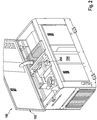
- FIG. 1 illustrates an example enclosure 100 containing a liquid container (e.g., a fuel tank) and other interior components.
- the example enclosure 100 of FIG. 1 is for a power system that provides electrical, hydraulic, and/or pneumatic power for any of a variety of activities.
- the example enclosure 100 is made of sheet metal panels.
- the enclosure 100 protects interior components from environmental conditions. Such interior components may include an engine, a generator, a fuel tank for the engine, electronic components, hydraulic components, pneumatic components, and/or the like.
- the fuel tank is not accessible from the exterior of the enclosure 100.
- the enclosure 100 includes an access door 102 that can be opened to provide access to the fuel tank, for example, to enable refilling of the fuel tank.
- the example enclosure 100 also includes multiple side panels.
- the side panel designated 104 includes an angled flange, which is shown in more detail in FIGS. 4 and 5 , to enable evacuation of spilled fuel from the interior of the enclosure 100.
- FIG. 2 illustrates the example enclosure 100 of FIG. 1 shown with its access door 102 opened to provide access to an example fuel tank 202 in the interior of the enclosure 100.
- the fuel tank 202 has a fill location 204 at a top of the fuel tank 202 (e.g., in a typical or intended orientation of the fuel tank 202).
- the fill location 204 is within an interior of the enclosure 100 and is accessible by opening the door 102.
- the fill location 204 within the interior of the enclosure 100 and is accessible through a hole in the enclosure 100 above the fill location 204.
- the fill location 204 extends from the fuel tank 202, which is on the interior of the enclosure 100, to the exterior of the enclosure 100 through a hole in the door 102.
- the hole may not be sealed, enabling the door 102 to be opened. Fuel spilled while filling the fuel tank 202 may flow and/or fall into the hole in the door 102, but is still captured as described in more detail below.
- FIG. 3 illustrates an overhead view of the fuel tank 202 of FIG. 2 in the enclosure 100 of FIGS. 1 and 2 .
- the fuel tank 202 includes a recessed fuel capture area 302 that collects fuel spilled from the fill location 204 and/or adjacent the fill location 204.
- the fuel capture area 302 is molded into the fuel tank 202.
- the fuel capture area 302 is molded into the fuel tank 202.
- the fuel capture area 302 may be implemented using a fuel capture tray or other configuration that is attachable or can otherwise be placed on the top of the fuel tank 202 to capture spilled fuel.
- the fuel tank 202 is adjacent a side of the enclosure 100.
- the fuel tank 202 further includes a channel 304 that directs fuel from the capture area 302 to an exterior of the enclosure 100 at the side of the fuel tank 202 near the side of the enclosure 100.
- the example channel 304 is molded as part of the example fuel tank 202.
- teh channel 304 is separate from the fuel tank 202 and may be attached to the fuel tank 202 or otherwise placed in fluid communication with the fuel capture area 302.
- FIG. 4 is another view of the fuel tank 202 of FIG. 2 and an angled flange 402 in the side panel 104 of the enclosure 100 configured to direct spilled fuel out from the interior of the enclosure 100. Fuel flowing from the fuel capture area 302 to the channel 304 falls onto the flange 402 and flows out to the exterior of the enclosure 100.
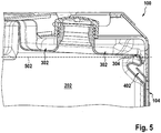
- FIG. 5 is a side view of the example fuel tank 202 of FIGS. 2-4 and the angled flange 402 of FIG. 4 .
- the capture area 302 is tilted toward the channel 304 to cause spilled fuel to flow toward the channel 304 and the flange 402.
- the tilt is illustrated with reference to a horizontal reference 502 (e.g., when the enclosure 100 is substantially level).
- the channel 304 laps the flange 402.
- the channel 304 and/or the flange 402 have alternative geometries, such as having the channel 304 terminate at the flange such that the flange 402 is a continuation of the structure of the channel 304. Any other geometries and/or physical relationships that cause the channel 304 and the flange 402 to direct the fuel from the fluid capture area 302 to the exterior of the enclosure 100 may be used.
- the channel 304 may extend directly to the exterior of the enclosure, or close enough to the exterior of the enclosure 100 to enable the momentum of the fuel flowing from the fuel capture area 302 through the channel 304 to eject the fuel from the enclosure 100 (e.g., via a hole in the enclosure).
- the channel 304 may include any appropriate geometries to direct the fuel from the fuel capture area 302 to the exterior of the enclosure 100 and/or to an intermediate structure (e.g., the flange 402) that directs the fuel outside of the enclosure 100.
- Disclosed examples enable fluid container fill locations to be located within the interior of an enclosure, which can improve protection of the fluid container and/or reduce the chances of contamination from environmental factors. Disclosed examples also reduce the complexity required to extend the fluid fill location from inside the enclosure to the outside. For example, the top of the enclosure can be one continuous door for easier component access for servicing, because stationary parts and/or fluid sealing components are not needed to extend the fuel fill location to the exterior of the enclosure (e.g., through which a neck of the fluid container can protrude).
- Disclosed examples enable spilled fluid to be evacuated without additional components.
- the fuel tank and the side panel of the illustrated examples in FIGS. 1-5 would be present regardless of the presence of the evacuation system. Accordingly, the features of the fuel tank and the side panel provide an effective fuel evacuation system without further components.
- Capture areas, channels, and fuel containers are disclosed having example shapes.
- the capture areas, the channels, and/or the fuel containers may have any other appropriate shape based on, for example, a size and/or shape of the enclosure, other components within the enclosure, and/or a capacity of the fuel containers.
- x and/or y means any element of the three-element set ⁇ (x), (y), (x, y) ⁇ . In other words, “x and/or y” means “one or both of x and y”.
- x, y, and/or z means any element of the seven-element set ⁇ (x), (y), (z), (x, y), (x, z), (y, z), (x, y, z) ⁇ . In other words, "x, y and/or z” means “one or more of x, y and z”.
- the term “exemplary” means serving as a non-limiting example, instance, or illustration.
- the terms “e.g.,” and “for example” set off lists of one or more non-limiting examples, instances, or illustrations.
Landscapes
- Engineering & Computer Science (AREA)
- Chemical & Material Sciences (AREA)
- Mechanical Engineering (AREA)
- Combustion & Propulsion (AREA)
- Transportation (AREA)
- Sustainable Energy (AREA)
- Life Sciences & Earth Sciences (AREA)
- Sustainable Development (AREA)
- General Engineering & Computer Science (AREA)
- Cooling, Air Intake And Gas Exhaust, And Fuel Tank Arrangements In Propulsion Units (AREA)
- Sampling And Sample Adjustment (AREA)
- Details Of Rigid Or Semi-Rigid Containers (AREA)
- Filling Or Discharging Of Gas Storage Vessels (AREA)
Abstract
Description
- Fluid containers to evacuate spilled fluid from the interior of an enclosure of the fluid container, substantially as illustrated by and described in connection with at least one of the figures, as set forth more completely in the claims.
-
-
FIG. 1 illustrates an example enclosure containing a liquid container and other interior components, in accordance with aspects of this disclosure. -
FIG. 2 illustrates the example enclosure ofFIG. 1 shown with its access door opened to provide access to an example fuel tank in the interior of the enclosure, in accordance with aspects of this disclosure. -
FIG. 3 illustrates an overhead view of the fuel tank ofFIG. 2 in the enclosure ofFIGS. 1 and2 . -
FIG. 4 is another view of the fuel tank ofFIG. 2 and an angled flange in the side panel of the enclosure configured to direct spilled fuel out from the interior of the enclosure. -
FIG. 5 is a side view of the example fuel tank ofFIGS. 2-4 and the angled flange ofFIG. 4 . - This invention relates to fluid spill containment of fluid containers that are contained within an outer enclosure. Disclosed examples are described with reference to fuel tanks (e.g., gasoline tanks, diesel fuel tanks, etc.) mounted within sheet metal enclosures containing, among other things, an engine, a generator, and/or electronic components. However, disclosed examples may be adapted for any type of container, any type of fluid, and/or any type of enclosure.
- Conventional fuel fill caps and fill necks are external to a product enclosure and implement fuel spill control techniques that generally cause the fuel to stay external to an outer enclosure. Such conventional techniques are designed to keep fuel from entering the enclosure.
- Fuel tanks that are largely or completely inside of an enclosure conventionally have fill locations that extend to the outside of an enclosure. The fill neck typically protrudes through the top or side of the enclosure and a sealing mechanism prevents fuel spillage from entering the enclosure. However, if the fuel fill location cannot be extended to the outside of the enclosure and the fuel fill location is accessed by opening a door of the enclosure, then fuel spilled during filling ends up inside the product enclosure.
- Disclosed examples evacuate spilled fuel from the enclosure, so that spilled fuel does not pose any risk (e.g., a risk of ignition or explosion). In some examples, the fuel container has a fill location on top of the fuel tank and evacuates liquid fuel spilled inside of the enclosure adjacent the fill location to a location outside of the enclosure. In some examples, the fuel tank fill neck is inside of a sheet metal enclosure. In some other examples, the fuel tank fill neck extends to an outside of the enclosure but does not include a seal. Without the seal, spilled fuel is permitted to penetrate the enclosure near the fill location but is subsequently evacuated from the enclosure.
- Disclosed examples include a recessed capture feature integrated into the top of a fuel tank around the fill neck. The recessed capture feature captures spilled fuel and prevents the spilled fuel from reaching other portions of the interior of the enclosure. The recessed capture feature is slanted to direct the liquid to the edge of the top of the fuel tank. The fuel is directed to a channel at the side of the tank. The channel permits the fuel to flow down the side of the tank, where the fuel runs off of the tank and onto a side panel of the enclosure, where the fuel exits the enclosure. The fuel tank laps the sheet metal side panel via an undercut in the fuel tank and an angled flange on the side panel. The tank undercut and the side panel lap direct fuel from the inside of the enclosure to the outside of the enclosure.
- As used herein, a container or tank being "within an enclosure" refers to portions of the container or tank being within the enclosure such that fluid spilled at a fluid inlet of the tank (e.g., while filling the tank with the fluid) would fall and/or flow to a location within the interior of the enclosure. For example, portions of the container or tank may be exposed to an exterior of the enclosure or outside of the enclosure (e.g., a channel of the container or tank, the inlet of the container or tank) while the container or tank is considered to be within the enclosure.
- Disclosed example systems include an enclosure and a fluid container within the enclosure. In the disclosed example systems, the fluid container includes a fluid capture area at a top of the fluid container and a channel at a side of the fluid container, where the fluid capture area directs the fluid to the channel and the channel directs the fluid from an interior of the enclosure to an exterior of the enclosure.
- In some examples, the fluid container is molded to include at least one of the fluid capture area or the channel. In some examples, the fluid container includes a fluid inlet at the top of the fluid container, where the fluid capture area is adjacent and below the fluid inlet. In some such examples, the fluid capture area surrounds the fluid inlet to capture the fluid in any direction with respect to the fluid inlet.
- In some example systems, the enclosure includes a door or removable panel to provide access to the fluid inlet. In some such examples, a fluid inlet of the fluid container is not accessible from an exterior of the enclosure when the door or the removable panel are in a closed position. In some example systems, the enclosure includes a flange to direct the fluid from the channel to the exterior of the enclosure. In some such examples, the channel laps the flange. In some examples, the fluid capture area is pitched toward the channel to direct the fluid to the channel. In some examples, the enclosure includes a side panel, where the fluid container is mounted in the enclosure adjacent the side panel, and the flange is integral with the side panel.
- Disclosed power systems include an enclosure, an engine installed within the enclosure, and a fuel tank installed within the enclosure to store fuel for the engine. In the example power systems, the fuel tank includes a fuel capture area at a top of the fuel tank, and a channel at a side of the fuel tank, where the fuel capture area directs the spilled fuel to the channel and the channel directs the spilled fuel from an interior of the enclosure to an exterior of the enclosure.
- In some examples, the fuel tank is molded to include at least one of the fuel capture area or the channel. In some example systems, the fuel tank includes a fuel inlet at the top of the fuel tank, the fuel capture area being adjacent and below the fuel inlet. In some such examples, the fuel capture area surrounds the fuel inlet to capture the spilled fuel in any direction with respect to the fuel inlet. In some examples, the enclosure includes a door or removable panel to provide access to the fuel inlet. In some such examples, a fuel inlet of the fuel tank is not accessible from an exterior of the enclosure when the door or the removable panel are in a closed position.
- In some example systems, the enclosure includes a flange to direct the fluid from the channel to the exterior of the enclosure. In some such examples, the channel laps the flange. In some examples, the fuel capture area is pitched toward the channel to direct the fuel to the channel. In some examples, the enclosure includes a side panel, where the fuel tank is mounted in the enclosure adjacent the side panel, and the flange is integral with the side panel.
-
FIG. 1 illustrates anexample enclosure 100 containing a liquid container (e.g., a fuel tank) and other interior components. Theexample enclosure 100 ofFIG. 1 is for a power system that provides electrical, hydraulic, and/or pneumatic power for any of a variety of activities. Theexample enclosure 100 is made of sheet metal panels. - The
enclosure 100 protects interior components from environmental conditions. Such interior components may include an engine, a generator, a fuel tank for the engine, electronic components, hydraulic components, pneumatic components, and/or the like. The fuel tank is not accessible from the exterior of theenclosure 100. Theenclosure 100 includes anaccess door 102 that can be opened to provide access to the fuel tank, for example, to enable refilling of the fuel tank. - As described in more detail below, the
example enclosure 100 also includes multiple side panels. The side panel designated 104 includes an angled flange, which is shown in more detail inFIGS. 4 and5 , to enable evacuation of spilled fuel from the interior of theenclosure 100. -
FIG. 2 illustrates theexample enclosure 100 ofFIG. 1 shown with itsaccess door 102 opened to provide access to anexample fuel tank 202 in the interior of theenclosure 100. Thefuel tank 202 has afill location 204 at a top of the fuel tank 202 (e.g., in a typical or intended orientation of the fuel tank 202). In the example ofFIG. 2 , thefill location 204 is within an interior of theenclosure 100 and is accessible by opening thedoor 102. In some other examples, thefill location 204 within the interior of theenclosure 100 and is accessible through a hole in theenclosure 100 above thefill location 204. In still other examples, thefill location 204 extends from thefuel tank 202, which is on the interior of theenclosure 100, to the exterior of theenclosure 100 through a hole in thedoor 102. In such examples, the hole may not be sealed, enabling thedoor 102 to be opened. Fuel spilled while filling thefuel tank 202 may flow and/or fall into the hole in thedoor 102, but is still captured as described in more detail below. -
FIG. 3 illustrates an overhead view of thefuel tank 202 ofFIG. 2 in theenclosure 100 ofFIGS. 1 and2 . As shown inFIG. 3 , thefuel tank 202 includes a recessedfuel capture area 302 that collects fuel spilled from thefill location 204 and/or adjacent thefill location 204. Thefuel capture area 302 is molded into thefuel tank 202. In the example ofFIG. 3 , thefuel capture area 302 is molded into thefuel tank 202. However, thefuel capture area 302 may be implemented using a fuel capture tray or other configuration that is attachable or can otherwise be placed on the top of thefuel tank 202 to capture spilled fuel. - As shown in
FIG. 3 , thefuel tank 202 is adjacent a side of theenclosure 100. Thefuel tank 202 further includes achannel 304 that directs fuel from thecapture area 302 to an exterior of theenclosure 100 at the side of thefuel tank 202 near the side of theenclosure 100. Theexample channel 304 is molded as part of theexample fuel tank 202. In other examples, tehchannel 304 is separate from thefuel tank 202 and may be attached to thefuel tank 202 or otherwise placed in fluid communication with thefuel capture area 302. -
FIG. 4 is another view of thefuel tank 202 ofFIG. 2 and anangled flange 402 in theside panel 104 of theenclosure 100 configured to direct spilled fuel out from the interior of theenclosure 100. Fuel flowing from thefuel capture area 302 to thechannel 304 falls onto theflange 402 and flows out to the exterior of theenclosure 100. -
FIG. 5 is a side view of theexample fuel tank 202 ofFIGS. 2-4 and theangled flange 402 ofFIG. 4 . As shown inFIG. 5 , thecapture area 302 is tilted toward thechannel 304 to cause spilled fuel to flow toward thechannel 304 and theflange 402. The tilt is illustrated with reference to a horizontal reference 502 (e.g., when theenclosure 100 is substantially level). - In the example of
FIGS. 4 and5 , thechannel 304 laps theflange 402. In other examples, thechannel 304 and/or theflange 402 have alternative geometries, such as having thechannel 304 terminate at the flange such that theflange 402 is a continuation of the structure of thechannel 304. Any other geometries and/or physical relationships that cause thechannel 304 and theflange 402 to direct the fuel from thefluid capture area 302 to the exterior of theenclosure 100 may be used. - While an example geometry of the
channel 304 is illustrated inFIGS. 3 ,4 , and5 , other geometries may be used to direct fluid fromfuel capture area 302 to an exterior of theenclosure 100. For example, thechannel 304 may extend directly to the exterior of the enclosure, or close enough to the exterior of theenclosure 100 to enable the momentum of the fuel flowing from thefuel capture area 302 through thechannel 304 to eject the fuel from the enclosure 100 (e.g., via a hole in the enclosure). Thechannel 304 may include any appropriate geometries to direct the fuel from thefuel capture area 302 to the exterior of theenclosure 100 and/or to an intermediate structure (e.g., the flange 402) that directs the fuel outside of theenclosure 100. - Disclosed examples enable fluid container fill locations to be located within the interior of an enclosure, which can improve protection of the fluid container and/or reduce the chances of contamination from environmental factors. Disclosed examples also reduce the complexity required to extend the fluid fill location from inside the enclosure to the outside. For example, the top of the enclosure can be one continuous door for easier component access for servicing, because stationary parts and/or fluid sealing components are not needed to extend the fuel fill location to the exterior of the enclosure (e.g., through which a neck of the fluid container can protrude).
- Disclosed examples enable spilled fluid to be evacuated without additional components. For example, the fuel tank and the side panel of the illustrated examples in
FIGS. 1-5 would be present regardless of the presence of the evacuation system. Accordingly, the features of the fuel tank and the side panel provide an effective fuel evacuation system without further components. - Capture areas, channels, and fuel containers are disclosed having example shapes. However, the capture areas, the channels, and/or the fuel containers may have any other appropriate shape based on, for example, a size and/or shape of the enclosure, other components within the enclosure, and/or a capacity of the fuel containers.
- As utilized herein, "and/or" means any one or more of the items in the list joined by "and/or". As an example, "x and/or y" means any element of the three-element set {(x), (y), (x, y)}. In other words, "x and/or y" means "one or both of x and y". As another example, "x, y, and/or z" means any element of the seven-element set {(x), (y), (z), (x, y), (x, z), (y, z), (x, y, z)}. In other words, "x, y and/or z" means "one or more of x, y and z". As utilized herein, the term "exemplary" means serving as a non-limiting example, instance, or illustration. As utilized herein, the terms "e.g.," and "for example" set off lists of one or more non-limiting examples, instances, or illustrations.
- While the present method and/or system has been described with reference to certain implementations, it will be understood by those skilled in the art that various changes may be made and equivalents may be substituted without departing from the scope of the present method and/or system. In addition, many modifications may be made to adapt a particular situation or material to the teachings of the present disclosure without departing from its scope. Therefore, the present method and/or system are not limited to the particular implementations disclosed.
Claims (11)
- A system, comprising:- an enclosure; and- a fluid container within the enclosure, the fluid container comprising:- a fluid capture area at a top of the fluid container; and- a channel at a side of the fluid container, the fluid capture area to direct the fluid to the channel, the channel to direct the fluid from an interior of the enclosure to an exterior of the enclosure.
- The system as defined in claim 1,
wherein the fluid container is molded to include at least one of the fluid capture area or the channel. - The system as defined in claim 1 or 2,
wherein the fluid container comprises a fluid inlet at the top of the fluid container, the fluid capture area being adjacent and below the fluid inlet. - The system as defined in claim 3,
wherein the fluid capture area surrounds the fluid inlet to capture the fluid in any direction with respect to the fluid inlet. - The system as defined in one of the preceding claims,
wherein the enclosure comprises a door or removable panel to provide access to the fluid inlet. - The system as defined in claim 5,
wherein a fluid inlet of the fluid container is not accessible from an exterior of the enclosure when the door or the removable panel are in a closed position. - The system as defined in one of the preceding claims,
wherein the enclosure comprises a flange to direct the fluid from the channel to the exterior of the enclosure. - The system as defined in claim 7,
wherein the channel laps the flange. - The system as defined in one of the preceding claims,
wherein the fluid capture area is pitched toward the channel to direct the fluid to the channel. - The system as defined in one of the preceding claims,
wherein the enclosure comprises a side panel, the fluid container being mounted in the enclosure adjacent the side panel, the flange being integral with the side panel. - The system as defined in one of the preceding claims,
further comprising an engine installed within the enclosure; wherein the fluid container is a fuel tank installed within the enclosure to store fuel for the engine, the fuel tank comprising:- a fuel capture area at a top of the fuel tank; and- a channel at a side of the fuel tank, the fuel capture area to direct the spilled fuel to the channel, the channel to direct the spilled fuel from an interior of the enclosure to an exterior of the enclosure.
Applications Claiming Priority (1)
| Application Number | Priority Date | Filing Date | Title |
|---|---|---|---|
| US15/140,692 US10150364B2 (en) | 2016-04-28 | 2016-04-28 | Fluid containers to evacuate spilled fluid from the interior of an enclosure of the fluid container |
Publications (1)
| Publication Number | Publication Date |
|---|---|
| EP3238974A1 true EP3238974A1 (en) | 2017-11-01 |
Family
ID=58017968
Family Applications (1)
| Application Number | Title | Priority Date | Filing Date |
|---|---|---|---|
| EP17155664.0A Withdrawn EP3238974A1 (en) | 2016-04-28 | 2017-02-10 | Fluid containers to evacuate spilled fluid from the interior of an enclosure of the fluid container |
Country Status (5)
| Country | Link |
|---|---|
| US (1) | US10150364B2 (en) |
| EP (1) | EP3238974A1 (en) |
| CN (1) | CN107401465B (en) |
| BR (1) | BR102017007041A2 (en) |
| MX (1) | MX385072B (en) |
Citations (4)
| Publication number | Priority date | Publication date | Assignee | Title |
|---|---|---|---|---|
| JPH02188621A (en) * | 1989-01-18 | 1990-07-24 | Honda Motor Co Ltd | Soundproof engine working machine |
| US20040168654A1 (en) * | 2003-02-28 | 2004-09-02 | Radtke David E. | Spatial relationship of components in engine-driven generator |
| US20150267652A1 (en) * | 2011-03-22 | 2015-09-24 | Illinois Tool Works Inc. | Systems and Methods for Controlling Fuel Vapor Flow in an Engine-Driven Generator |
| EP2962925A1 (en) * | 2014-07-04 | 2016-01-06 | Honda Motor Co., Ltd. | Fuel tank structure for saddle-ride type vehicle |
Family Cites Families (12)
| Publication number | Priority date | Publication date | Assignee | Title |
|---|---|---|---|---|
| US4013105A (en) * | 1975-06-09 | 1977-03-22 | Briggs & Stratton Corporation | Spilled fuel diverter for small engines |
| US5785099A (en) * | 1995-02-28 | 1998-07-28 | Mir Saied Kashani | Automobile refueling guard |
| CN2409082Y (en) * | 1999-12-22 | 2000-12-06 | 光阳工业股份有限公司 | Motorcycle fuel tank safety oil drain diversion device |
| US6279781B1 (en) * | 2000-02-07 | 2001-08-28 | Ronald C. Konar | Boxed liquid drip catcher |
| US7216778B2 (en) * | 2004-11-29 | 2007-05-15 | Todd Kaeb | Self-leveling drip catcher for fluid containers |
| JP2008162512A (en) * | 2006-12-28 | 2008-07-17 | Yamaha Motor Co Ltd | Saddle riding vehicle |
| CN201325320Y (en) * | 2008-12-01 | 2009-10-14 | 重庆宗申技术开发研究有限公司 | Oil tank of micro-tillage machine |
| CN202557284U (en) * | 2012-04-26 | 2012-11-28 | 刘家富 | Anti-leakage oil tank |
| CN202832898U (en) * | 2012-08-30 | 2013-03-27 | 百力通(上海)国际贸易有限公司 | Oil overflow preventing engine oil tank |
| US8800609B1 (en) * | 2013-03-18 | 2014-08-12 | Jodi Krechowiecki | Fuel bib |
| JP5836336B2 (en) * | 2013-08-26 | 2015-12-24 | 本田技研工業株式会社 | Saddle riding vehicle |
| CN203769984U (en) * | 2014-04-02 | 2014-08-13 | 山东华盛中天机械集团股份有限公司 | Fuel oil guiding plate part |
-
2016
- 2016-04-28 US US15/140,692 patent/US10150364B2/en active Active
-
2017
- 2017-02-10 EP EP17155664.0A patent/EP3238974A1/en not_active Withdrawn
- 2017-04-05 BR BR102017007041-7A patent/BR102017007041A2/en not_active Application Discontinuation
- 2017-04-10 CN CN201710227205.7A patent/CN107401465B/en not_active Expired - Fee Related
- 2017-04-24 MX MX2017005353A patent/MX385072B/en unknown
Patent Citations (4)
| Publication number | Priority date | Publication date | Assignee | Title |
|---|---|---|---|---|
| JPH02188621A (en) * | 1989-01-18 | 1990-07-24 | Honda Motor Co Ltd | Soundproof engine working machine |
| US20040168654A1 (en) * | 2003-02-28 | 2004-09-02 | Radtke David E. | Spatial relationship of components in engine-driven generator |
| US20150267652A1 (en) * | 2011-03-22 | 2015-09-24 | Illinois Tool Works Inc. | Systems and Methods for Controlling Fuel Vapor Flow in an Engine-Driven Generator |
| EP2962925A1 (en) * | 2014-07-04 | 2016-01-06 | Honda Motor Co., Ltd. | Fuel tank structure for saddle-ride type vehicle |
Also Published As
| Publication number | Publication date |
|---|---|
| MX2017005353A (en) | 2018-08-20 |
| CN107401465A (en) | 2017-11-28 |
| BR102017007041A2 (en) | 2017-10-31 |
| US20170313175A1 (en) | 2017-11-02 |
| CN107401465B (en) | 2021-08-17 |
| MX385072B (en) | 2025-03-14 |
| US10150364B2 (en) | 2018-12-11 |
Similar Documents
| Publication | Publication Date | Title |
|---|---|---|
| EP1415844B1 (en) | Dust cover lock system for vehicle filler neck | |
| US5380604A (en) | Lead accumulator | |
| US5197627A (en) | Double walled storage tank | |
| EP2607135B1 (en) | Fuel ventilation system valve | |
| US6532983B2 (en) | System for venting a liquid tank | |
| EP1627761A2 (en) | Fuel-dispensing nozzle inhibitor | |
| US20100313969A1 (en) | Fuel filler assembly | |
| US7246642B2 (en) | Breakaway closure for capless tank filler neck | |
| CA2136494A1 (en) | Screw necks for openings in the container wall and/or bottom of sheet metal containers | |
| US20070000574A1 (en) | Fuel and vapor vent management system for filler neck | |
| RU2695837C1 (en) | Transport-storage container for liquids | |
| US7225795B2 (en) | System and method for controlling fuel vapor emission in a small engine | |
| US8763626B2 (en) | Valve for the venting circuit of a liquid tank | |
| CA2957206C (en) | Fluid containers to evacuate spilled fluid from the interior of an enclosure of the fluid container | |
| US10150364B2 (en) | Fluid containers to evacuate spilled fluid from the interior of an enclosure of the fluid container | |
| CN105197388A (en) | Tank filling system | |
| US9061581B2 (en) | Liquid container for a motor vehicle, in particular a fuel container | |
| US20050040130A1 (en) | Fluid container for facilitating dispensing of fluid therefrom and related methods | |
| US6685043B1 (en) | Quick fill | |
| KR20190080084A (en) | Oilmist vent apparatus | |
| US5899249A (en) | Fuel spill collector device | |
| US4162020A (en) | Anti-spill device | |
| CN218948935U (en) | Oil filling pipe throat, oil filling pipe and vehicle | |
| EP3149296B1 (en) | Liquid return system for internal combustion engine | |
| JP7121342B2 (en) | Reductant inlet structure |
Legal Events
| Date | Code | Title | Description |
|---|---|---|---|
| PUAI | Public reference made under article 153(3) epc to a published international application that has entered the european phase |
Free format text: ORIGINAL CODE: 0009012 |
|
| STAA | Information on the status of an ep patent application or granted ep patent |
Free format text: STATUS: REQUEST FOR EXAMINATION WAS MADE |
|
| 17P | Request for examination filed |
Effective date: 20170210 |
|
| AK | Designated contracting states |
Kind code of ref document: A1 Designated state(s): AL AT BE BG CH CY CZ DE DK EE ES FI FR GB GR HR HU IE IS IT LI LT LU LV MC MK MT NL NO PL PT RO RS SE SI SK SM TR |
|
| AX | Request for extension of the european patent |
Extension state: BA ME |
|
| STAA | Information on the status of an ep patent application or granted ep patent |
Free format text: STATUS: EXAMINATION IS IN PROGRESS |
|
| 17Q | First examination report despatched |
Effective date: 20200123 |
|
| STAA | Information on the status of an ep patent application or granted ep patent |
Free format text: STATUS: THE APPLICATION IS DEEMED TO BE WITHDRAWN |
|
| 18D | Application deemed to be withdrawn |
Effective date: 20210720 |