EP3238893A1 - Robot system - Google Patents
Robot system Download PDFInfo
- Publication number
- EP3238893A1 EP3238893A1 EP14908919.5A EP14908919A EP3238893A1 EP 3238893 A1 EP3238893 A1 EP 3238893A1 EP 14908919 A EP14908919 A EP 14908919A EP 3238893 A1 EP3238893 A1 EP 3238893A1
- Authority
- EP
- European Patent Office
- Prior art keywords
- operation region
- speed operation
- speed
- low
- robot
- Prior art date
- Legal status (The legal status is an assumption and is not a legal conclusion. Google has not performed a legal analysis and makes no representation as to the accuracy of the status listed.)
- Granted
Links
Images


Classifications
-
- G—PHYSICS
- G05—CONTROLLING; REGULATING
- G05B—CONTROL OR REGULATING SYSTEMS IN GENERAL; FUNCTIONAL ELEMENTS OF SUCH SYSTEMS; MONITORING OR TESTING ARRANGEMENTS FOR SUCH SYSTEMS OR ELEMENTS
- G05B19/00—Program-control systems
- G05B19/02—Program-control systems electric
- G05B19/18—Numerical control [NC], i.e. automatically operating machines, in particular machine tools, e.g. in a manufacturing environment, so as to execute positioning, movement or co-ordinated operations by means of program data in numerical form
- G05B19/406—Numerical control [NC], i.e. automatically operating machines, in particular machine tools, e.g. in a manufacturing environment, so as to execute positioning, movement or co-ordinated operations by means of program data in numerical form characterised by monitoring or safety
- G05B19/4061—Avoiding collision or forbidden zones
-
- B—PERFORMING OPERATIONS; TRANSPORTING
- B25—HAND TOOLS; PORTABLE POWER-DRIVEN TOOLS; MANIPULATORS
- B25J—MANIPULATORS; CHAMBERS PROVIDED WITH MANIPULATION DEVICES
- B25J9/00—Program-controlled manipulators
- B25J9/16—Program controls
- B25J9/1656—Program controls characterised by programming, planning systems for manipulators
- B25J9/1664—Program controls characterised by programming, planning systems for manipulators characterised by motion, path, trajectory planning
- B25J9/1666—Avoiding collision or forbidden zones
-
- B—PERFORMING OPERATIONS; TRANSPORTING
- B25—HAND TOOLS; PORTABLE POWER-DRIVEN TOOLS; MANIPULATORS
- B25J—MANIPULATORS; CHAMBERS PROVIDED WITH MANIPULATION DEVICES
- B25J19/00—Accessories fitted to manipulators, e.g. for monitoring, for viewing; Safety devices combined with or specially adapted for use in connection with manipulators
- B25J19/06—Safety devices
-
- B—PERFORMING OPERATIONS; TRANSPORTING
- B25—HAND TOOLS; PORTABLE POWER-DRIVEN TOOLS; MANIPULATORS
- B25J—MANIPULATORS; CHAMBERS PROVIDED WITH MANIPULATION DEVICES
- B25J9/00—Program-controlled manipulators
- B25J9/16—Program controls
- B25J9/1615—Program controls characterised by special kind of manipulator, e.g. planar, scara, gantry, cantilever, space, closed chain, passive/active joints and tendon driven manipulators
- B25J9/162—Mobile manipulator, movable base with manipulator arm mounted on it
-
- B—PERFORMING OPERATIONS; TRANSPORTING
- B25—HAND TOOLS; PORTABLE POWER-DRIVEN TOOLS; MANIPULATORS
- B25J—MANIPULATORS; CHAMBERS PROVIDED WITH MANIPULATION DEVICES
- B25J9/00—Program-controlled manipulators
- B25J9/16—Program controls
- B25J9/1628—Program controls characterised by the control loop
- B25J9/1651—Program controls characterised by the control loop acceleration, rate control
-
- B—PERFORMING OPERATIONS; TRANSPORTING
- B25—HAND TOOLS; PORTABLE POWER-DRIVEN TOOLS; MANIPULATORS
- B25J—MANIPULATORS; CHAMBERS PROVIDED WITH MANIPULATION DEVICES
- B25J9/00—Program-controlled manipulators
- B25J9/16—Program controls
- B25J9/1674—Program controls characterised by safety, monitoring, diagnostic
-
- B—PERFORMING OPERATIONS; TRANSPORTING
- B25—HAND TOOLS; PORTABLE POWER-DRIVEN TOOLS; MANIPULATORS
- B25J—MANIPULATORS; CHAMBERS PROVIDED WITH MANIPULATION DEVICES
- B25J9/00—Program-controlled manipulators
- B25J9/16—Program controls
- B25J9/1674—Program controls characterised by safety, monitoring, diagnostic
- B25J9/1676—Avoiding collision or forbidden zones
-
- G—PHYSICS
- G05—CONTROLLING; REGULATING
- G05B—CONTROL OR REGULATING SYSTEMS IN GENERAL; FUNCTIONAL ELEMENTS OF SUCH SYSTEMS; MONITORING OR TESTING ARRANGEMENTS FOR SUCH SYSTEMS OR ELEMENTS
- G05B2219/00—Program-control systems
- G05B2219/30—Nc systems
- G05B2219/40—Robotics, robotics mapping to robotics vision
- G05B2219/40202—Human robot coexistence
-
- G—PHYSICS
- G05—CONTROLLING; REGULATING
- G05B—CONTROL OR REGULATING SYSTEMS IN GENERAL; FUNCTIONAL ELEMENTS OF SUCH SYSTEMS; MONITORING OR TESTING ARRANGEMENTS FOR SUCH SYSTEMS OR ELEMENTS
- G05B2219/00—Program-control systems
- G05B2219/30—Nc systems
- G05B2219/42—Servomotor, servo controller kind till VSS
- G05B2219/42288—Limit, stop drive current if axis obstructed, blocked, force against stop
Definitions
- the present invention relates to a robot system in which an operator and a robot exist together to work in the same work space.
- a safety fence is typically provided to completely separate a work space of a robot and a work space of an operator from each other to prevent a situation in which the robot and the operator work in the same work space at the same time.
- the safety fence inhibits the operator from physically entering a movable range of the robot during an operation of the robot. In this way, safety for the operator is secured. Examples of techniques for supporting this are as follows.
- Patent Literature 1 discloses that a limit region which limits the operation of a robot is set in a handover region where an object is handed over between the robot and the operator when it is detected that the operator has entered the handover region.
- Patent Literature 2 discloses that a limit region is set with respect to coordinate values of the tip end of an arm of the robot, and a speed of the arm is limited based on a distance with this limit region.
- an object of the present invention is to improve safety for an operator and work efficiency, in a robot system in which the operator and the robot exist together to work in the same work space.
- a robot system in which an operator and a robot exist together to work in a same work space, comprises a robot including a robot arm including a plurality of links coupled to each other via joints; a control section which controls an operation of the robot arm; and a collision stop section which detects that the robot arm has collided against an object and stops the robot arm, wherein a high-speed operation region and a low-speed operation region are set for the robot arm, wherein the control section is configured to operate the robot arm at a speed that is equal to or lower than a first maximum speed, in the high-speed operation region, and operate the robot arm at a speed that is equal to or lower than a second maximum speed lower than the first maximum speed, in the low-speed operation region, and wherein the collision stop section is configured to change a collision detection sensitivity between the high-speed operation region and the low-speed operation region so that the collision detection sensitivity in the high-speed operation region becomes lower than the collision detection sensitivity in the low-speed operation region.
- misdetection rate a probability of the misdetection due to a noise or the like
- the collision stop section changes the collision detection sensitivity between the high-speed operation region and the low-speed operation region so that the collision detection sensitivity in the high-speed operation region becomes lower than the collision detection sensitivity in the low-speed operation region. Therefore, compared to a case where the collision detection sensitivity is not changed between the high-speed operation region and the low-speed operation region, the maximum operation speed in the high-speed operation region can be set to be higher than that in the low-speed operation region, while maintaining the misdetection rate at a constant value in the high-speed operation region and the low-speed operation region.
- a region of the operation region of the robot arm, which is closer to the work region of the operator, is set as the low-speed operation region, and the collision detection sensitivity in the low-speed operation region is set to be as high as possible.
- the robot arm collides against the operator at a low speed, and can be stopped with a high sensitivity.
- the robot arm can be operated at a speed that is as high as possible in the high-speed operation region.
- the collision stop section may be configured to change the collision detection sensitivity so that the collision detection sensitivity in the high-speed operation region becomes zero. In accordance with this configuration, it is not necessary to take the misdetection of the collision into account. Therefore, the robot arm can be operated at a high speed in the high-speed operation region within a range of allowable performance of the robot arm. This can increase work efficiency.
- a region of an operation region of the robot arm, which is closer to a work region of the operator, may be set as the low-speed operation region, and a region of the operation region of the robot arm, which is other than the low-speed operation region, may be set as the high-speed operation region.
- the robot arm collides against the operator at a low speed, and can be stopped with a high sensitivity.
- the control section may be configured to operate the links which are entirely located in the high-speed operation region at a speed that is equal to or lower than the first maximum speed and operate the links which are at least partially located in the low-speed operation region at a speed that is equal to or lower than the second maximum speed.
- At least one intermediate-speed operation region may be provided between the high-speed operation region and the low-speed operation region in such a manner that the high-speed operation region, the at least one intermediate-speed operation region, and the low-speed operation region are arranged in this order, and the control section may be configured to operate the robot arm in the at least one intermediate-speed operation region, at a speed that is equal to or lower than a third maximum speed lower than the first maximum speed and at a speed that is equal to or lower than a fourth maximum speed higher than the second maximum speed, the first maximum speed, the third maximum speed, the fourth maximum speed, and the second maximum speed decreasing in this order, in a direction from the high-speed operation region toward the low-speed operation region.
- the maximum speed of the robot arm can be gradually changed.
- the collision stop section may be configured to change the collision detection sensitivity so that the collision detection sensitivity in the high-speed operation region, the collision detection sensitivity in the at least one intermediate-speed operation region, and the collision detection sensitivity in the low-speed operation region are increased in this order, in the high-speed operation region, the at least one intermediate-speed operation region, and the low-speed operation region.
- the collision detection sensitivity can be gradually changed.
- the controller may operate the robot arm at a speed that is equal to or lower than the maximum speed corresponding to the relative low-speed operation region, from a location that is farther from the relative low-speed operation region than a boundary between the relative high-speed operation region and the relative low-speed operation region is, and in a case where the control section moves the robot arm from the relative low-speed operation region to the relative high-speed operation region, the control section may operate the robot arm at a speed that is equal to or lower than the maximum speed corresponding to the relative high-speed operation region, from a location that is farther from the relative high-speed operation region.
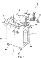
- Fig. 1 is a perspective view showing the configuration of a robot system according to Embodiment 1.
- a robot system 1 includes a robot body (hereinafter this will be simply referred to as a robot) 2, and a controller 3 which controls the robot 2.
- the robot system 1 is a system in which an operator and the robot 2 exist together to work in the same work space.
- the robot 2 is a robot including a robot arm including a plurality of links which are coupled to each other via joints.
- the robot 2 is a Selective Compliance Assembly Robot Arm (SCARA) robot which is of a coaxial and dual-arm type.
- the robot 2 includes a lower arm 10 disposed on a base 9, and an upper arm 12 disposed on the lower arm 10.
- the lower arm 10 includes a first link 10a and a second link 10b which are coupled to each other via a joint.
- the upper arm 12 includes a first link 12a and a second link 12b which are coupled to each other via a joint.
- the controller 3 is connected to the robot 2 via a control line (not shown).
- the controller 3 is, for example, a robot controller including a computer such as a microcontroller.
- the controller 3 is not a single controller but may include a plurality of controllers.
- the controller 3 is accommodated in, for example, a carriage 4.
- the carriage 4 includes a body 4a with a rectangular parallelepiped box shape, a handle 4b attached on the upper portion of the body 4a, and wheels 4c provided on four corners of the bottom surface of the body 4a.
- Fig. 2 is a schematic view showing a joint structure of the lower arm 10 and the upper arm 12.
- the lower arm 10 includes a first axis 21 which is a rotary (rotational) joint, a second axis 22 which is a rotary (rotational) joint, and a third axis 23 which is a translational (prismatic) joint.
- the lower arm 10 has three degrees of freedom of the first axis 21, the second axis 22, and the third axis 23.
- the upper arm 12 includes a fourth axis 24 which is a rotary (rotational) joint, a fifth axis 25 which is a rotary (rotational) joint, and a sixth axis 26 which is a translational (prismatic) joint.
- the upper arm 12 has three degrees of freedom of the fourth axis 24, the fifth axis 25, and the sixth axis 26.
- a support member 10s is provided on the upper surface of the base 9.
- a first end portion of the first link 10a horizontally extending is coupled to the support member 10s via the first axis 21 having a rotational axis vertical to the base 9.
- a second end portion of the first link 10a is coupled to a first end portion of the second link 10b via the second axis 22 having a vertical rotational axis.
- the second link 10b horizontally extends.
- a first end effector 11 is coupled to a second end portion of the second link 10b via the third axis 23 having a vertical translational direction. In this configuration, the third axis 23 allows the first end effector 11 to be movable up and down, at the tip end portion of the second link 10b.
- a support member 12s is provided on the upper surface of the first link 10a of the lower arm 10.
- a first end portion of a first link 12a horizontally extending is coupled to the support member 12s via the fourth axis 24 having a vertical rotational axis.
- the fourth axis 24 is disposed in such a manner that the rotational axis of the fourth axis 24 conforms to that of the first axis 21.
- a second end portion of the first link 12a is coupled to a first end portion of the second link 12b via the fifth axis 25 having a vertical rotational axis.
- the second link 12b horizontally extends.
- a second end effector 13 is coupled to a second end portion of the second link 12b via the sixth axis 26 having a vertical translational direction.
- the sixth axis 26 allows the second end effector 13 to be movable up and down, at the tip end portion of the second link 12b.
- the reference position of the first end effector 11 and the reference position of the second end effector 13 are set to positions on the same horizontal plane (see Fig. 1 )
- the axes 21 to 26 included in the lower arm 10 and the upper arm 12 are driven by a servo mechanism (not shown).
- the servo mechanism includes a driving unit which displaces the arms, and a transmission mechanism which transmits a driving force of the driving unit to the arms.
- a driving unit is constituted by electric motors, for example, servo motors.
- the lower arm 10 and the upper arm 12 are operated by the servo mechanism in response to a command provided by the controller 3.
- the controller 3 controls the positions of the servo motors to control the operation of the lower arm 10 and the operation of the upper arm 12 at desired speeds.
- the fourth axis 24 of the upper arm 12 is connected to the first axis 21 of the lower arm 10 via the support member 12s and the first link 10a of the lower arm 10 in such a manner that the fourth axis 24 and the first axis 21 of the lower arm 10 have the common rotational axis.
- the fourth axis 24 of the upper arm 12 is controlled to perform a specified rotation so that the rotation of the first axis 21 is cancelled.
- Fig. 3 is a plan view of the robot system 1.
- the robot system 1 is introduced into, for example, a production line, and is configured to work (operate) in a line where the operator works.
- the robot 2 of the robot system 1 has a reference coordinate system (hereinafter will be referred to as a base coordinate system).
- a base coordinate system In this coordinate system, for example, an intersection of an installation surface of the base 9 and the rotational axis of the first axis 21 (see Fig.
- the rotational axis of the first axis 21 is a Z-axis
- an arbitrary axis orthogonal to the Z-axis is a X-axis
- an axis orthogonal to the Z-axis and the X-axis is a Y-axis.
- An operation region 20 of the lower arm 10 and the upper arm 12 of the robot 2 is set based on this base coordinate system as a reference.
- the operation region 20 is set to have a rectangular shape in a plan view which covers a work table 5 placed in front of the robot 2. On the work table 5, for example, four kinds of workpieces W1, W2, W3, W4 are placed.
- the robot 2 is configured to work (perform an operation) in the operation region 20, as in the operators.
- Regions on the right and left sides of the operation region 20 are works regions, respectively, where the operators perform work steps on the work table 5.
- the operator located on the left side supplies the workpiece (material member) W1 to the robot 2.
- the robot 2 attaches the workpiece (first part)W2 and the workpiece (second part) W3 to the workpiece (material member) W1 supplied to the robot 2 to finish the workpiece (finished product) W4.
- the operator located on the right side performs a next work step for the workpiece (finished product) W4.
- the controller 3 controls the operation of the lower arm 10 and the operation of the upper arm 12 so that the lower arm 10 and the upper arm 12 operate within the operation region 20.
- the operation region 20 includes a high-speed operation region 20H and low-speed operation regions 20L. Regions with a rectangular shape in a plan (top) view, of the operation region 20, which are closer to work regions of the operators, respectively, are set as the low-speed operation regions 20L. A region of the operation region 20, which is other than the low-speed operation regions 20L, and has a rectangular shape in a plan view, is set as the high-speed operation region 20H. In the present embodiment, the low-speed operation regions 20L are set on the right and left sides of the high-speed operation region 20H, respectively.
- the controller 3 is configured to operate the lower arm 10 and the upper arm 12 at a speed that is equal to or lower than a first maximum speed in the high-speed operation region 20H, and operate the lower arm 10 and the upper arm 12 at a speed that is equal to or lower than a second maximum speed lower than the first maximum speed in each of the low-speed operation regions 20L.
- the second maximum speed in the low-speed operation regions 20L is set to, for example, 250mm/s defined as a low speed control in ISO10218-1. With this control, the lower arm 10 and the upper arm 12 can be operated at a speed that is as high as possible, in the high-speed operation region 20H. As a result, the work (operation) efficiency of the robot 2 can be increased.
- the controller 3 is configured to operate the links which are entirely located in the high-speed operation region 20H at the speed that is equal to or lower than the first maximum speed and operate the links which are at least partially located in each of the low-speed operation regions 20L at the speed that is equal to or lower than the second maximum speed. With this control, safety for the operators can be secured more reliably.
- the controller 3 moves the lower arm 10 and the upper arm 12, from the high-speed operation region 20H to each of the low-speed operation regions 20L, the controller 3 gradually reduces the operation speeds of the arms.
- the controller 3 moves the lower arm 10 and the upper arm 12 from each of the low-speed operation regions 20L to the high-speed operation region 20H, the controller 3 gradually increases the operation speeds of the arms. This can suppress a rapid change in the operation speeds. Therefore, safety is improved.
- the controller 3 has a collision stop function of detecting a collision of the lower arm 10 or the upper arm 12 against an object and stopping the operation of the lower arm 10 or the operation of the upper arm 12.
- the controller 3 is configured to change a collision detection sensitivity between the high-speed operation region 20H and each of the low-speed operation regions 20L so that the collision detection sensitivity in the high-speed operation region 20H becomes lower than that in each of the low-speed operation regions 20L.
- the controller 3 includes a movement amount directing section 31, a current generating circuit 32, a collision detecting section 33, a current limiting section 34, and an interface section 35.
- the controller 3 is implemented by, for example, a processor such as a computer or a microcontroller.
- the controller 3 executes predetermined programs to implement the movement amount directing section 31, the collision detecting section 33, and the current limiting section 34.
- Fig. 4 shows a servo motor 28 as a driving device which drives the axes 21 to 26 included in the lower arm 10 and the upper arm 12.
- a servo motor 28 is shown in Fig. 4 , other servo motors 28 have the same configuration.
- An encoder 29 which detects the position of the servo motor 28 (rotational angle position of a rotor with respect to a reference rotational angle position), and a current sensor 30 which detects the value of a current flowing through the servo motor 28 are attached on the servo motor 28.
- the controller 3 is configured to obtain the position of the servo motor 28 which is detected by the encoder 29 and the value of the current flowing through the servo motor 28 which is detected by the current sensor 30, via the interface section 35.
- the movement amount directing section 31 calculates a current command value based on a predetermined position command value and the detected position information from the encoder 29.
- the movement amount directing section 31 calculates the current command value required to move the lower arm 10 and the upper arm 12 to the high-speed operation region 20H or the low-speed operation region 20L.
- the controller 3 provides the current command value calculated by the movement amount directing section 31 to the current generating circuit 32.
- the current generating circuit 32 generates a current in accordance with the current command value provided by the movement amount directing section 31, and flows the generated current through the servo motor 28.
- the current generating circuit 32 is an amplifier which generates a driving current of the servo motor 28 in accordance with the current command value, namely, a servo amplifier. Since the positions of the servo motors 28 of the axes 21 to 26 are controlled in the above-described manner, the controller 3 can operate the lower arm 10 and the upper arm 12 at the speed that is equal to or lower than the first maximum speed in the high-speed operation region 20H and at the speed that is equal to or lower than the second maximum speed lower than the first maximum speed in each of the low-speed operation regions 20L.
- the controller 3 calculates the position information of the links in the base coordinate system as the reference, by coordinate transformation. In this way, the controller 3 can operate the links which are entirely located in the high-speed operation region 20H at the speed that is equal to or lower than the first maximum speed and operate the links which are at least partially located in each of the low-speed operation regions 20L at the speed that is equal to or lower than the second maximum speed.
- the collision detecting section 33 detects that the lower arm 10 or the upper arm 12 has collided against the object, based on the detected position information from the encoder 29 and the current value from the current sensor 30, and outputs a collision detection signal indicating that the lower arm 10 or the upper arm 12 has collided against the object, to the current limiting section 34, which will be described later.
- the current limiting section 34 limits the current command value calculated by the movement amount directing section 31, and provides the limited current command value to the current generating circuit 32. In this way, when the collision detecting section 33 detects that the lower arm 10 or the upper arm 12 has collided against the object, the current output from the current generating circuit 32 is reduced to be less than that which is not limited, and the reduced current is supplied to the servo motor 28. Limiting the current may be reducing the current command value provided by the movement amount directing section 31 in a predetermined reduction ratio, or limiting the current to a predetermined constant value without relation to (independently of) the current command value provided by the movement amount directing section 31. This includes a case where the predetermined reduction ratio is 0%. In this case, in limiting the current, the current supplied from the current generating circuit 32 to the servo motor 28 is zero. The supply of the current to the servo motor 28 is inhibited.
- the controller 3 repeats this process at constant time intervals (e.g., every 20msec).
- the collision detecting section 33 calculates torque generated in the axes 21 to 26 (see Fig. 2 ) included in the lower arm 10 and the upper arm 12 of the robot 2, based on variables indicating the positions at given time, of the axes 21 to 26 (step S1).
- the collision detecting section 33 calculates the torque by use of a motion equation of a typical robot.
- the collision detecting section 33 calculates a current required for each of the servo motors 28 to generate the calculated torque (hereinafter this current will be referred to as a theoretical current value) (step S2).
- the collision detecting section 33 obtains the value of a current actually flowing through each of the servo motors 28 (hereinafter this current will be referred to as an actual current value) which is detected by the current sensor 30, and calculates a difference current value indicating an absolute value of a difference between the theoretical current value and the actual current value (step S3).
- the collision detecting section 33 determines whether or not the difference current value is larger than a first reference value set for each of the axes (step S4). In a case where the collision detecting section 33 determines that the difference current value is larger than the first reference value, the collision detecting section 33 determines that the collision has occurred, and outputs the collision detection signal indicating that the collision has been detected to the current limiting section 34 (see Fig. 4 ) (step S5). Then, the current limiting section 34 provides the limited current command value to the current generating circuit 32, and stops (ceases) current supply to the servo motor 28 (step S6).
- the collision detecting section 33 determines that the difference current value is less than the first reference value in step S4, calculates a differential difference current value (change speed (rate) of the difference current value) which is a differential value of the difference current value (step S7), and determines whether or not the differential difference current value is larger than a second reference value set for each of the axes 21 to 26 (step S8).
- the collision detecting section 33 determines that the collision has occurred, and moves to step S5 and the following steps.
- the collision detecting section 33 determines that the collision has not occurred, and returns to start (normal position control process).
- the collision detecting section 33 is configured to detect the collision against the obstacle based on the actual current value of the current supplied to the servo motor 28 for driving each of the axes 21 to 26 included in the lower arm 10 and the upper arm 12 of the robot 2. Therefore, it is not necessary to provide a torque sensor or an observer to detect the collision, and the configuration can be simplified.
- the collision detecting section 33 determines that the collision has occurred in a case where the change amount of the difference current value is larger than the first reference value or the differential difference current value indicating the change speed of the difference current value is larger than the second reference value. Therefore, the collision can be detected more quickly and more accurately, irrespective of the magnitude of the driving speed of a member to be driven.
- the collision detection sensitivity will be described. If the first reference value and the second reference value in determination of the collision (step S4 and step S8) are set to be smaller, the collision detection sensitivity can be increased. However, the set values of the first reference value and the second reference value are too small, misdetection may occur frequently, for example, a fluctuation of the driving current due to an electric noise or the like is determined as occurrence of the collision. Therefore, reliability of the collision detection is low. On the other hand, if the set values of the first reference value and the second reference value are too large, the collision detection sensitivity is reduced, and collision detection timing is retarded. In view of this, it is necessary to properly set the first reference value and the second reference value to quickly and accurately detect the collision.
- the collision detecting section 33 changes the collision detection sensitivity between the high-speed operation region 20H and each of the low-speed operation regions 20L so that the collision detection sensitivity in the high-speed operation region 20H becomes lower than that in each of the low-speed operation regions 20L.
- the first reference value and the second reference value in the high-speed operation region 20H are set to be higher than those in each of the low-speed operation regions 20L.
- the first reference value and the second reference value are set so that the collision detection sensitivity in the high-speed operation region 20H becomes zero. In this setting, it is not necessary to take misdetection of the collision into account. Therefore, the robot arm can be operated at a high speed in the high-speed operation region 20H within a range of allowable performance of the robot arm. This can increase work efficiency.
- misdetection rate a probability of the misdetection due to the noise or the like
- the collision detection sensitivity is increased (threshold signal level at which it is determined that the collision has occurred is reduced).
- misdetection rate is increased as the operation speed of the robot arm is increased, like the present embodiment.
- the collision detecting section 33 changes the collision detection sensitivity between the high-speed operation region 20H and each of the low-speed operation regions 20L so that the collision detection sensitivity in the high-speed operation region 20H becomes lower than that in each of the low-speed operation regions 20L. Therefore, compared to a case where the collision detection sensitivity is not changed between the high-speed operation region 20H and each of the low-speed operation regions 20L, the maximum operation speed in the high-speed operation region 20H can be set to be higher than that in each of the low-speed operation regions 20L, while maintaining the misdetection rate at a constant value in the high-speed operation region 20H and each of the low-speed operation regions 20L.
- the regions of the operation region 20 of the robot arm (the lower arm 10 and the upper arm 12), which are closer to the work regions of the operators, respectively, are set as the low-speed operation regions 20L, and the collision detection sensitivity in each of the low-speed operation regions 20L is set to be as high as possible.
- the robot arm (the lower arm 10 and the upper arm 12) collides against the operator at a low speed, and can be stopped with a high sensitivity.
- the robot arm can be operated at a speed that is as high as possible in the high-speed operation region 20H.
- the robot 2 of the present embodiment is the robot of a coaxial and dual-arm type.
- the robot 2 can be disposed in a small space, and is capable of performing an operation similar to detailed manual work performed by the operator. Therefore, the robot 2 can easily replace the operator in the production line.
- At least one intermediate-speed operation region 20M may be provided between the high-speed operation region 20H and the low-speed operation region 20L in such a manner that the high-speed operation region 20H, the at least one intermediate-speed operation region 20M, and the low-speed operation region 20L are arranged in this order.
- the controller 3 may be configured to operate the robot arm in the at least one intermediate-speed operation region 20M, at a speed that is equal to or lower than a third maximum speed lower than the first maximum speed and a speed that is equal to or lower than a fourth maximum speed higher than the second maximum speed, the first maximum speed, the third maximum speed, the fourth maximum speed, and the second maximum speed decreasing in this order, in a direction from the high-speed operation region 20H toward the low-speed operation region 20L.
- the maximum speed of the robot arm (10, 12) can be gradually changed.
- the maximum speed can be set in multiple stages.
- the collision detecting section 33 may be configured to change the collision detection sensitivity in the high-speed operation region 20H, the at least one intermediate-speed operation region 20M, and the low-speed operation region 20L in such a manner that the collision detection sensitivity is increased in the direction from the high-speed operation region 20H toward the low-speed operation region 20L. In this way, the collision detection sensitivity can be gradually changed, and can be set in multiple stages.
- the controller 3 moves the robot arm (10, 12) from a region corresponding to a higher maximum speed (hereinafter this region will be referred to as a relative high-speed operation region) to a region corresponding to a lower maximum speed (hereinafter this region will be referred to as a relative low-speed operation region), which are two adjacent regions, among the high-speed operation region 20H, the at least one intermediate-speed operation region 20M, and the low-speed operation region 20L
- the controller 3 operates the robot arm (10, 12) at a speed that is equal to or lower than the maximum speed corresponding to the relative low-speed operation region, from a location that is farther from the relative low-speed operation region than a boundary between the relative high-speed operation region and the relative low-speed operation region is.
- the controller 3 moves the robot arm (10, 12) from the relative low-speed operation region to the relative high-speed operation region
- the controller 3 operates the robot arm (10, 12) at a speed that is equal to or lower than the maximum speed corresponding to the relative high-speed operation region, from a location that is farther from the relative high-speed operation region than the boundary between the relative high-speed operation region and the relative low-speed operation region is.
- the operation of the robot arm (10, 12) is changed to a low-speed operation before the robot arm (10, 12) enters the relative low-speed operation region.
- the collision detecting section 33 promptly stops the operation of the robot arm (10, 12) after detection of the collision
- the present invention is not limited to this.
- the controller 3 may perform a stress relieving process for relieving a stress generated between the member to be driven and the obstacle, due to the collision. Specifically, the controller 3 detects whether or not the arm has collided against the obstacle, and controls the operation of the arm so that the arm is moved away a specified distance from the obstacle based on a path before the collision, in a case where the controller 3 detects that the arm has collided against the obstacle. More specifically, in the case of detection of the collision, the collision detecting section 33 performs the following operation.
- the collision detecting section 33 performs a retracting process for moving the axis in a direction opposite to that of the movement of the axis before the collision.
- the collision detecting section 33 performs an advancing process for moving the axis in the same direction as that of the movement of the axis before the collision. This can mitigate an impact of the collision. As a result, safety can be further improved.
- the collision detection sensitivity (the first reference value, the second reference value) at the detection of the collision is manually set, and is changed (switched) between the high-speed operation region 20H and the low-speed operation region 20L
- the collision detection sensitivity may be automatically set.
- the controller 3 causes the robot 2 to perform particular work (operation), the robot 2 to learn maximum torque generated in each of the axes 21 to 26 in every operation of the robot 2, and sets the first reference value and the second reference value based on the learned maximum torque. This makes it possible to set the collision detection sensitivity to an optimal value corresponding to an operation environment.
- the controller 3 changes the speed between the high-speed operation region 20H and the low-speed operation region 20L, by software processing, for example, the controller 3 may determine that the arm has moved beyond the region by use of a hardware such as a sensor.
- the collision detecting section 33 detects the collision based on the detected position information and the detected current value of the servo motor 28, this is merely exemplary.
- the robot system 1 may include a vision sensor attached on the arm, and the controller 3 may detect that the arm has collided against the obstacle based on an image taken by the vision sensor.
- the collision detection function of the present embodiment can be replaced or assisted by the vision sensor.
- another collision detection sensor such as an acceleration sensor or a pressure sensor may be used.
- the robot 2 is the SCARA robot of a coaxial and dual-arm type, this is merely exemplary.
- the robot 2 may be a single arm robot or a vertical articulated robot.
- the high-speed operation region 20H and each of the low-speed operation regions 20L have a rectangular shape when viewed from above (in a plan view), this is merely exemplary, and the high-speed operation region 20H and each of the low-speed operation regions 20L may have a desired shape.
- the present invention is effectively used in a robot system in which an operator and a robot exist together to work in the same work space.
Landscapes
- Engineering & Computer Science (AREA)
- Robotics (AREA)
- Mechanical Engineering (AREA)
- Human Computer Interaction (AREA)
- Manufacturing & Machinery (AREA)
- Physics & Mathematics (AREA)
- General Physics & Mathematics (AREA)
- Automation & Control Theory (AREA)
- Health & Medical Sciences (AREA)
- General Health & Medical Sciences (AREA)
- Orthopedic Medicine & Surgery (AREA)
- Manipulator (AREA)
Abstract
Description
- The present invention relates to a robot system in which an operator and a robot exist together to work in the same work space.
- Conventionally, in an industrial robot system, a safety fence is typically provided to completely separate a work space of a robot and a work space of an operator from each other to prevent a situation in which the robot and the operator work in the same work space at the same time. The safety fence inhibits the operator from physically entering a movable range of the robot during an operation of the robot. In this way, safety for the operator is secured. Examples of techniques for supporting this are as follows.
Patent Literature 1 discloses that a limit region which limits the operation of a robot is set in a handover region where an object is handed over between the robot and the operator when it is detected that the operator has entered the handover region.Patent Literature 2 discloses that a limit region is set with respect to coordinate values of the tip end of an arm of the robot, and a speed of the arm is limited based on a distance with this limit region. -
- Patent Literature 1: Japanese Laid-Open Patent Application Publication No.
2014-180725 - Patent Literature 2: Japanese Laid-Open Patent Application Publication No.
Hei. 11-347983 - In recent years, there has been a demand for improvement of a productivity, by introducing the robot into a production line, and operating the robot in the production line where the operator works.
- However, in the above-described conventional techniques, to secure safety for the operator who works in the production line where the robot works (operates), it is necessary to provide the safety fence, or the like. This increases introduction cost of the robot, and is undesirable. Thus, in a case where the robot is introduced into the production line and works in the production line where the operator works, high safety cannot be obtained in the conventional techniques.
- In view of the above-described circumstances, an object of the present invention is to improve safety for an operator and work efficiency, in a robot system in which the operator and the robot exist together to work in the same work space.
- According to an aspect of the present invention, a robot system in which an operator and a robot exist together to work in a same work space, comprises a robot including a robot arm including a plurality of links coupled to each other via joints; a control section which controls an operation of the robot arm; and a collision stop section which detects that the robot arm has collided against an object and stops the robot arm, wherein a high-speed operation region and a low-speed operation region are set for the robot arm, wherein the control section is configured to operate the robot arm at a speed that is equal to or lower than a first maximum speed, in the high-speed operation region, and operate the robot arm at a speed that is equal to or lower than a second maximum speed lower than the first maximum speed, in the low-speed operation region, and wherein the collision stop section is configured to change a collision detection sensitivity between the high-speed operation region and the low-speed operation region so that the collision detection sensitivity in the high-speed operation region becomes lower than the collision detection sensitivity in the low-speed operation region.
- In general, in collision detection that detects that the robot arm has collided against an object, there is a tendency that a probability of the misdetection (hereinafter this will be referred to as a misdetection rate) due to a noise or the like is increased, as the collision detection sensitivity is increased (threshold signal level at which it is determined that the collision has occurred is reduced), and the misdetection rate is increased as the operation speed of the robot arm is increased.
- In accordance with the above-described configuration, the collision stop section changes the collision detection sensitivity between the high-speed operation region and the low-speed operation region so that the collision detection sensitivity in the high-speed operation region becomes lower than the collision detection sensitivity in the low-speed operation region. Therefore, compared to a case where the collision detection sensitivity is not changed between the high-speed operation region and the low-speed operation region, the maximum operation speed in the high-speed operation region can be set to be higher than that in the low-speed operation region, while maintaining the misdetection rate at a constant value in the high-speed operation region and the low-speed operation region.
- A region of the operation region of the robot arm, which is closer to the work region of the operator, is set as the low-speed operation region, and the collision detection sensitivity in the low-speed operation region is set to be as high as possible. In this setting, even in a case where the operator contacts the robot arm, the robot arm collides against the operator at a low speed, and can be stopped with a high sensitivity. In contrast, the robot arm can be operated at a speed that is as high as possible in the high-speed operation region. As a result, compared to a case where the collision detection sensitivity is not changed between the high-speed operation region and the low-speed operation region, safety for the operator can be improved, and the work efficiency can be increased.
- The collision stop section may be configured to change the collision detection sensitivity so that the collision detection sensitivity in the high-speed operation region becomes zero. In accordance with this configuration, it is not necessary to take the misdetection of the collision into account. Therefore, the robot arm can be operated at a high speed in the high-speed operation region within a range of allowable performance of the robot arm. This can increase work efficiency.
- In the above robot system, a region of an operation region of the robot arm, which is closer to a work region of the operator, may be set as the low-speed operation region, and a region of the operation region of the robot arm, which is other than the low-speed operation region, may be set as the high-speed operation region.
- In accordance with this configuration, even if the operator contacts the robot arm, the robot arm collides against the operator at a low speed, and can be stopped with a high sensitivity.
- The control section may be configured to operate the links which are entirely located in the high-speed operation region at a speed that is equal to or lower than the first maximum speed and operate the links which are at least partially located in the low-speed operation region at a speed that is equal to or lower than the second maximum speed.
- In accordance with this configuration, safety for the operator can be secured more reliably.
- At least one intermediate-speed operation region may be provided between the high-speed operation region and the low-speed operation region in such a manner that the high-speed operation region, the at least one intermediate-speed operation region, and the low-speed operation region are arranged in this order, and the control section may be configured to operate the robot arm in the at least one intermediate-speed operation region, at a speed that is equal to or lower than a third maximum speed lower than the first maximum speed and at a speed that is equal to or lower than a fourth maximum speed higher than the second maximum speed, the first maximum speed, the third maximum speed, the fourth maximum speed, and the second maximum speed decreasing in this order, in a direction from the high-speed operation region toward the low-speed operation region.
- In accordance with this configuration, the maximum speed of the robot arm can be gradually changed.
- The collision stop section may be configured to change the collision detection sensitivity so that the collision detection sensitivity in the high-speed operation region, the collision detection sensitivity in the at least one intermediate-speed operation region, and the collision detection sensitivity in the low-speed operation region are increased in this order, in the high-speed operation region, the at least one intermediate-speed operation region, and the low-speed operation region.
- In accordance with this configuration, the collision detection sensitivity can be gradually changed.
- In a case where the control section moves the robot arm from a region corresponding to a higher maximum speed (hereinafter this region will be referred to as a relative high-speed operation region) to a region corresponding to a lower maximum speed (hereinafter this region will be referred to as a relative low-speed operation region), which are two adjacent regions, among the high-speed operation region, the at least one intermediate-speed operation region , and the low-speed operation region, the controller may operate the robot arm at a speed that is equal to or lower than the maximum speed corresponding to the relative low-speed operation region, from a location that is farther from the relative low-speed operation region than a boundary between the relative high-speed operation region and the relative low-speed operation region is, and in a case where the control section moves the robot arm from the relative low-speed operation region to the relative high-speed operation region, the control section may operate the robot arm at a speed that is equal to or lower than the maximum speed corresponding to the relative high-speed operation region, from a location that is farther from the relative high-speed operation region than the boundary between the relative high-speed operation region and the relative low-speed operation region is.
- In accordance with this configuration, in a case where the control section moves the robot arm from the relative high-speed operation region to the relative low-speed operation region, the operation of the robot arm is changed to a low-speed operation before the robot arm enters the relative low-speed operation region. Therefore, safety can be improved compared to a case where the maximum speed does not have hysteresis characteristics. In contrast, in a case where the control section moves the robot arm from the relative low-speed operation region to the relative high-speed operation region, the operation of the robot arm is changed to a high-speed operation before the robot arm enters the relative high-speed operation region. Therefore, work efficiency can be increased compared to a case where the maximum speed does not have hysteresis characteristics.
- In accordance with the present invention, it becomes possible to provide a robot system in which an operator and a robot can exit together to work in the same work space while securing safety.
-
-
Fig. 1 is a perspective view showing the configuration of a robot system according toEmbodiment 1. -
Fig. 2 is a schematic view showing a joint structure of a robot arm ofFig. 1 . -
Fig. 3 is a plan view of the robot system ofFig. 1 . -
Fig. 4 is a block diagram showing the configuration of a controller of the robot system ofFig. 1 . -
Fig. 5 is a flowchart for explaining a process for detecting a collision of the robot arm ofFig. 1 . - Hereinafter, the embodiment of the present invention will be described with reference to the accompanying drawings. Throughout the drawings, the same or corresponding constituents are identified by the same reference symbols and will not be described repeatedly.
-
Fig. 1 is a perspective view showing the configuration of a robot system according toEmbodiment 1. As shown inFig. 1 , arobot system 1 includes a robot body (hereinafter this will be simply referred to as a robot) 2, and acontroller 3 which controls therobot 2. Therobot system 1 is a system in which an operator and therobot 2 exist together to work in the same work space. - It is sufficient that the
robot 2 is a robot including a robot arm including a plurality of links which are coupled to each other via joints. In the present embodiment, therobot 2 is a Selective Compliance Assembly Robot Arm (SCARA) robot which is of a coaxial and dual-arm type. Therobot 2 includes alower arm 10 disposed on abase 9, and anupper arm 12 disposed on thelower arm 10. Thelower arm 10 includes afirst link 10a and asecond link 10b which are coupled to each other via a joint. Theupper arm 12 includes afirst link 12a and asecond link 12b which are coupled to each other via a joint. - The
controller 3 is connected to therobot 2 via a control line (not shown). Thecontroller 3 is, for example, a robot controller including a computer such as a microcontroller. Thecontroller 3 is not a single controller but may include a plurality of controllers. In the present embodiment, thecontroller 3 is accommodated in, for example, acarriage 4. Thecarriage 4 includes abody 4a with a rectangular parallelepiped box shape, ahandle 4b attached on the upper portion of thebody 4a, andwheels 4c provided on four corners of the bottom surface of thebody 4a. -
Fig. 2 is a schematic view showing a joint structure of thelower arm 10 and theupper arm 12. As shown in Fig. 12, thelower arm 10 includes afirst axis 21 which is a rotary (rotational) joint, asecond axis 22 which is a rotary (rotational) joint, and a third axis 23 which is a translational (prismatic) joint. Thelower arm 10 has three degrees of freedom of thefirst axis 21, thesecond axis 22, and the third axis 23. Theupper arm 12 includes afourth axis 24 which is a rotary (rotational) joint, afifth axis 25 which is a rotary (rotational) joint, and asixth axis 26 which is a translational (prismatic) joint. Theupper arm 12 has three degrees of freedom of thefourth axis 24, thefifth axis 25, and thesixth axis 26. - In the
lower arm 10, asupport member 10s is provided on the upper surface of thebase 9. A first end portion of thefirst link 10a horizontally extending is coupled to thesupport member 10s via thefirst axis 21 having a rotational axis vertical to thebase 9. A second end portion of thefirst link 10a is coupled to a first end portion of thesecond link 10b via thesecond axis 22 having a vertical rotational axis. Thesecond link 10b horizontally extends. Afirst end effector 11 is coupled to a second end portion of thesecond link 10b via the third axis 23 having a vertical translational direction. In this configuration, the third axis 23 allows thefirst end effector 11 to be movable up and down, at the tip end portion of thesecond link 10b. - In the
upper arm 12, asupport member 12s is provided on the upper surface of thefirst link 10a of thelower arm 10. A first end portion of afirst link 12a horizontally extending is coupled to thesupport member 12s via thefourth axis 24 having a vertical rotational axis. Thefourth axis 24 is disposed in such a manner that the rotational axis of thefourth axis 24 conforms to that of thefirst axis 21. A second end portion of thefirst link 12a is coupled to a first end portion of thesecond link 12b via thefifth axis 25 having a vertical rotational axis. Thesecond link 12b horizontally extends. Asecond end effector 13 is coupled to a second end portion of thesecond link 12b via thesixth axis 26 having a vertical translational direction. In this configuration, thesixth axis 26 allows thesecond end effector 13 to be movable up and down, at the tip end portion of thesecond link 12b. The reference position of thefirst end effector 11 and the reference position of thesecond end effector 13 are set to positions on the same horizontal plane (seeFig. 1 ) - The
axes 21 to 26 included in thelower arm 10 and theupper arm 12 are driven by a servo mechanism (not shown). The servo mechanism includes a driving unit which displaces the arms, and a transmission mechanism which transmits a driving force of the driving unit to the arms. In the present embodiment, a driving unit is constituted by electric motors, for example, servo motors. Thelower arm 10 and theupper arm 12 are operated by the servo mechanism in response to a command provided by thecontroller 3. In other words, thecontroller 3 controls the positions of the servo motors to control the operation of thelower arm 10 and the operation of theupper arm 12 at desired speeds. Thefourth axis 24 of theupper arm 12 is connected to thefirst axis 21 of thelower arm 10 via thesupport member 12s and thefirst link 10a of thelower arm 10 in such a manner that thefourth axis 24 and thefirst axis 21 of thelower arm 10 have the common rotational axis. Thefourth axis 24 of theupper arm 12 is controlled to perform a specified rotation so that the rotation of thefirst axis 21 is cancelled. -
Fig. 3 is a plan view of therobot system 1. As shown inFig. 3 , therobot system 1 is introduced into, for example, a production line, and is configured to work (operate) in a line where the operator works. Therobot 2 of therobot system 1 has a reference coordinate system (hereinafter will be referred to as a base coordinate system). In this coordinate system, for example, an intersection of an installation surface of thebase 9 and the rotational axis of the first axis 21 (seeFig. 2 ) of thelower arm 10 is an origin, the rotational axis of thefirst axis 21 is a Z-axis, an arbitrary axis orthogonal to the Z-axis is a X-axis, and an axis orthogonal to the Z-axis and the X-axis is a Y-axis. Anoperation region 20 of thelower arm 10 and theupper arm 12 of therobot 2 is set based on this base coordinate system as a reference. In the present embodiment, theoperation region 20 is set to have a rectangular shape in a plan view which covers a work table 5 placed in front of therobot 2. On the work table 5, for example, four kinds of workpieces W1, W2, W3, W4 are placed. Therobot 2 is configured to work (perform an operation) in theoperation region 20, as in the operators. Regions on the right and left sides of theoperation region 20 are works regions, respectively, where the operators perform work steps on the work table 5. For example, the operator located on the left side supplies the workpiece (material member) W1 to therobot 2. Therobot 2 attaches the workpiece (first part)W2 and the workpiece (second part) W3 to the workpiece (material member) W1 supplied to therobot 2 to finish the workpiece (finished product) W4. The operator located on the right side performs a next work step for the workpiece (finished product) W4. - The
controller 3 controls the operation of thelower arm 10 and the operation of theupper arm 12 so that thelower arm 10 and theupper arm 12 operate within theoperation region 20. Theoperation region 20 includes a high-speed operation region 20H and low-speed operation regions 20L. Regions with a rectangular shape in a plan (top) view, of theoperation region 20, which are closer to work regions of the operators, respectively, are set as the low-speed operation regions 20L. A region of theoperation region 20, which is other than the low-speed operation regions 20L, and has a rectangular shape in a plan view, is set as the high-speed operation region 20H. In the present embodiment, the low-speed operation regions 20L are set on the right and left sides of the high-speed operation region 20H, respectively. - The
controller 3 is configured to operate thelower arm 10 and theupper arm 12 at a speed that is equal to or lower than a first maximum speed in the high-speed operation region 20H, and operate thelower arm 10 and theupper arm 12 at a speed that is equal to or lower than a second maximum speed lower than the first maximum speed in each of the low-speed operation regions 20L. The second maximum speed in the low-speed operation regions 20L is set to, for example, 250mm/s defined as a low speed control in ISO10218-1. With this control, thelower arm 10 and theupper arm 12 can be operated at a speed that is as high as possible, in the high-speed operation region 20H. As a result, the work (operation) efficiency of therobot 2 can be increased. - The
controller 3 is configured to operate the links which are entirely located in the high-speed operation region 20H at the speed that is equal to or lower than the first maximum speed and operate the links which are at least partially located in each of the low-speed operation regions 20L at the speed that is equal to or lower than the second maximum speed. With this control, safety for the operators can be secured more reliably. - Further, in a case where the
controller 3 moves thelower arm 10 and theupper arm 12, from the high-speed operation region 20H to each of the low-speed operation regions 20L, thecontroller 3 gradually reduces the operation speeds of the arms. On the other hand, in a case where thecontroller 3 moves thelower arm 10 and theupper arm 12 from each of the low-speed operation regions 20L to the high-speed operation region 20H, thecontroller 3 gradually increases the operation speeds of the arms. This can suppress a rapid change in the operation speeds. Therefore, safety is improved. - Further, the
controller 3 has a collision stop function of detecting a collision of thelower arm 10 or theupper arm 12 against an object and stopping the operation of thelower arm 10 or the operation of theupper arm 12. Thecontroller 3 is configured to change a collision detection sensitivity between the high-speed operation region 20H and each of the low-speed operation regions 20L so that the collision detection sensitivity in the high-speed operation region 20H becomes lower than that in each of the low-speed operation regions 20L. With this control, even if the operator contacts thelower arm 10 or theupper arm 12, thelower arm 10 or theupper arm 12 collides against the operator at a low speed, and can be stopped with a high sensitivity. In addition, thelower arm 10 or theupper arm 12 can be operated at a speed that is as high as possible in the high-speed operation region 20H. - Hereinafter, the specific configuration of the
controller 3 which realizes the above-described functions will be described with reference to the block diagram ofFig. 4 . As shown inFig. 4 , thecontroller 3 includes a movementamount directing section 31, acurrent generating circuit 32, acollision detecting section 33, a current limitingsection 34, and aninterface section 35. Thecontroller 3 is implemented by, for example, a processor such as a computer or a microcontroller. Thecontroller 3 executes predetermined programs to implement the movementamount directing section 31, thecollision detecting section 33, and the current limitingsection 34. -
Fig. 4 shows aservo motor 28 as a driving device which drives theaxes 21 to 26 included in thelower arm 10 and theupper arm 12. Although oneservo motor 28 is shown inFig. 4 ,other servo motors 28 have the same configuration. Anencoder 29 which detects the position of the servo motor 28 (rotational angle position of a rotor with respect to a reference rotational angle position), and acurrent sensor 30 which detects the value of a current flowing through theservo motor 28 are attached on theservo motor 28. Thecontroller 3 is configured to obtain the position of theservo motor 28 which is detected by theencoder 29 and the value of the current flowing through theservo motor 28 which is detected by thecurrent sensor 30, via theinterface section 35. - The movement
amount directing section 31 calculates a current command value based on a predetermined position command value and the detected position information from theencoder 29. The movementamount directing section 31 calculates the current command value required to move thelower arm 10 and theupper arm 12 to the high-speed operation region 20H or the low-speed operation region 20L. In a normal state in which thelower arm 10 and theupper arm 12 do not collide against an obstacle, thecontroller 3 provides the current command value calculated by the movementamount directing section 31 to thecurrent generating circuit 32. - The
current generating circuit 32 generates a current in accordance with the current command value provided by the movementamount directing section 31, and flows the generated current through theservo motor 28. Thecurrent generating circuit 32 is an amplifier which generates a driving current of theservo motor 28 in accordance with the current command value, namely, a servo amplifier. Since the positions of theservo motors 28 of theaxes 21 to 26 are controlled in the above-described manner, thecontroller 3 can operate thelower arm 10 and theupper arm 12 at the speed that is equal to or lower than the first maximum speed in the high-speed operation region 20H and at the speed that is equal to or lower than the second maximum speed lower than the first maximum speed in each of the low-speed operation regions 20L. In addition, thecontroller 3 calculates the position information of the links in the base coordinate system as the reference, by coordinate transformation. In this way, thecontroller 3 can operate the links which are entirely located in the high-speed operation region 20H at the speed that is equal to or lower than the first maximum speed and operate the links which are at least partially located in each of the low-speed operation regions 20L at the speed that is equal to or lower than the second maximum speed. - The
collision detecting section 33 detects that thelower arm 10 or theupper arm 12 has collided against the object, based on the detected position information from theencoder 29 and the current value from thecurrent sensor 30, and outputs a collision detection signal indicating that thelower arm 10 or theupper arm 12 has collided against the object, to the current limitingsection 34, which will be described later. - Receiving the collision detection signal from the
collision detecting section 33, the current limitingsection 34 limits the current command value calculated by the movementamount directing section 31, and provides the limited current command value to thecurrent generating circuit 32. In this way, when thecollision detecting section 33 detects that thelower arm 10 or theupper arm 12 has collided against the object, the current output from thecurrent generating circuit 32 is reduced to be less than that which is not limited, and the reduced current is supplied to theservo motor 28. Limiting the current may be reducing the current command value provided by the movementamount directing section 31 in a predetermined reduction ratio, or limiting the current to a predetermined constant value without relation to (independently of) the current command value provided by the movementamount directing section 31. This includes a case where the predetermined reduction ratio is 0%. In this case, in limiting the current, the current supplied from thecurrent generating circuit 32 to theservo motor 28 is zero. The supply of the current to theservo motor 28 is inhibited. - Next, a collision detection process performed by the
controller 3 will be described with reference to the flowchart ofFig. 5 . Thecontroller 3 repeats this process at constant time intervals (e.g., every 20msec). - Initially, the collision detecting section 33 (see
Fig. 4 ) calculates torque generated in theaxes 21 to 26 (seeFig. 2 ) included in thelower arm 10 and theupper arm 12 of therobot 2, based on variables indicating the positions at given time, of theaxes 21 to 26 (step S1). The collision detecting section 33 (seeFig. 4 ) calculates the torque by use of a motion equation of a typical robot. - Then, the
collision detecting section 33 calculates a current required for each of theservo motors 28 to generate the calculated torque (hereinafter this current will be referred to as a theoretical current value) (step S2). - Then, the
collision detecting section 33 obtains the value of a current actually flowing through each of the servo motors 28 (hereinafter this current will be referred to as an actual current value) which is detected by thecurrent sensor 30, and calculates a difference current value indicating an absolute value of a difference between the theoretical current value and the actual current value (step S3). - Then, the
collision detecting section 33 determines whether or not the difference current value is larger than a first reference value set for each of the axes (step S4). In a case where thecollision detecting section 33 determines that the difference current value is larger than the first reference value, thecollision detecting section 33 determines that the collision has occurred, and outputs the collision detection signal indicating that the collision has been detected to the current limiting section 34 (seeFig. 4 ) (step S5). Then, the current limitingsection 34 provides the limited current command value to thecurrent generating circuit 32, and stops (ceases) current supply to the servo motor 28 (step S6). - On the other hand, in a case where the
collision detecting section 33 determines that the difference current value is less than the first reference value in step S4, thecollision detecting section 33 calculates a differential difference current value (change speed (rate) of the difference current value) which is a differential value of the difference current value (step S7), and determines whether or not the differential difference current value is larger than a second reference value set for each of theaxes 21 to 26 (step S8). In a case where thecollision detecting section 33 determines that the differential difference current value is larger than the second reference value, thecollision detecting section 33 determines that the collision has occurred, and moves to step S5 and the following steps. On the other hand, in a case where thecollision detecting section 33 determines that the differential difference current value is less than the second reference value, thecollision detecting section 33 determines that the collision has not occurred, and returns to start (normal position control process). - As described above, in the present embodiment, the
collision detecting section 33 is configured to detect the collision against the obstacle based on the actual current value of the current supplied to theservo motor 28 for driving each of theaxes 21 to 26 included in thelower arm 10 and theupper arm 12 of therobot 2. Therefore, it is not necessary to provide a torque sensor or an observer to detect the collision, and the configuration can be simplified. - The
collision detecting section 33 determines that the collision has occurred in a case where the change amount of the difference current value is larger than the first reference value or the differential difference current value indicating the change speed of the difference current value is larger than the second reference value. Therefore, the collision can be detected more quickly and more accurately, irrespective of the magnitude of the driving speed of a member to be driven. - Next, the collision detection sensitivity will be described. If the first reference value and the second reference value in determination of the collision (step S4 and step S8) are set to be smaller, the collision detection sensitivity can be increased. However, the set values of the first reference value and the second reference value are too small, misdetection may occur frequently, for example, a fluctuation of the driving current due to an electric noise or the like is determined as occurrence of the collision. Therefore, reliability of the collision detection is low. On the other hand, if the set values of the first reference value and the second reference value are too large, the collision detection sensitivity is reduced, and collision detection timing is retarded. In view of this, it is necessary to properly set the first reference value and the second reference value to quickly and accurately detect the collision.
- In the present embodiment, the
collision detecting section 33 changes the collision detection sensitivity between the high-speed operation region 20H and each of the low-speed operation regions 20L so that the collision detection sensitivity in the high-speed operation region 20H becomes lower than that in each of the low-speed operation regions 20L. In other words, the first reference value and the second reference value in the high-speed operation region 20H are set to be higher than those in each of the low-speed operation regions 20L. In the present embodiment, the first reference value and the second reference value are set so that the collision detection sensitivity in the high-speed operation region 20H becomes zero. In this setting, it is not necessary to take misdetection of the collision into account. Therefore, the robot arm can be operated at a high speed in the high-speed operation region 20H within a range of allowable performance of the robot arm. This can increase work efficiency. - As described above, in the collision detection that detects that the robot arm has collided against the object, there is a tendency that a probability of the misdetection (hereinafter this will be referred to as a misdetection rate) due to the noise or the like is increased, as the collision detection sensitivity is increased (threshold signal level at which it is determined that the collision has occurred is reduced). Also, there is a tendency that the misdetection rate is increased as the operation speed of the robot arm is increased, like the present embodiment.
- In accordance with the present embodiment, the
collision detecting section 33 changes the collision detection sensitivity between the high-speed operation region 20H and each of the low-speed operation regions 20L so that the collision detection sensitivity in the high-speed operation region 20H becomes lower than that in each of the low-speed operation regions 20L. Therefore, compared to a case where the collision detection sensitivity is not changed between the high-speed operation region 20H and each of the low-speed operation regions 20L, the maximum operation speed in the high-speed operation region 20H can be set to be higher than that in each of the low-speed operation regions 20L, while maintaining the misdetection rate at a constant value in the high-speed operation region 20H and each of the low-speed operation regions 20L. - The regions of the
operation region 20 of the robot arm (thelower arm 10 and the upper arm 12), which are closer to the work regions of the operators, respectively, are set as the low-speed operation regions 20L, and the collision detection sensitivity in each of the low-speed operation regions 20L is set to be as high as possible. In this setting, even in a case where the operator contacts the robot arm (thelower arm 10 and the upper arm 12), the robot arm (thelower arm 10 and the upper arm 12) collides against the operator at a low speed, and can be stopped with a high sensitivity. In contrast, the robot arm can be operated at a speed that is as high as possible in the high-speed operation region 20H. - As a result, compared to a case where the collision detection sensitivity is not changed between the high-
speed operation region 20H and each of the low-speed operation regions 20L, safety for the operators can be improved, and the work efficiency can be increased. - The
robot 2 of the present embodiment is the robot of a coaxial and dual-arm type. Therobot 2 can be disposed in a small space, and is capable of performing an operation similar to detailed manual work performed by the operator. Therefore, therobot 2 can easily replace the operator in the production line. - In other embodiments, at least one intermediate-speed operation region 20M (not shown) may be provided between the high-
speed operation region 20H and the low-speed operation region 20L in such a manner that the high-speed operation region 20H, the at least one intermediate-speed operation region 20M, and the low-speed operation region 20L are arranged in this order. Thecontroller 3 may be configured to operate the robot arm in the at least one intermediate-speed operation region 20M, at a speed that is equal to or lower than a third maximum speed lower than the first maximum speed and a speed that is equal to or lower than a fourth maximum speed higher than the second maximum speed, the first maximum speed, the third maximum speed, the fourth maximum speed, and the second maximum speed decreasing in this order, in a direction from the high-speed operation region 20H toward the low-speed operation region 20L. In this way, the maximum speed of the robot arm (10, 12) can be gradually changed. The maximum speed can be set in multiple stages. - The
collision detecting section 33 may be configured to change the collision detection sensitivity in the high-speed operation region 20H, the at least one intermediate-speed operation region 20M, and the low-speed operation region 20L in such a manner that the collision detection sensitivity is increased in the direction from the high-speed operation region 20H toward the low-speed operation region 20L. In this way, the collision detection sensitivity can be gradually changed, and can be set in multiple stages. - Further, in a case where the
controller 3 moves the robot arm (10, 12) from a region corresponding to a higher maximum speed (hereinafter this region will be referred to as a relative high-speed operation region) to a region corresponding to a lower maximum speed (hereinafter this region will be referred to as a relative low-speed operation region), which are two adjacent regions, among the high-speed operation region 20H, the at least one intermediate-speed operation region 20M, and the low-speed operation region 20L, thecontroller 3 operates the robot arm (10, 12) at a speed that is equal to or lower than the maximum speed corresponding to the relative low-speed operation region, from a location that is farther from the relative low-speed operation region than a boundary between the relative high-speed operation region and the relative low-speed operation region is. Also, in a case where thecontroller 3 moves the robot arm (10, 12) from the relative low-speed operation region to the relative high-speed operation region, thecontroller 3 operates the robot arm (10, 12) at a speed that is equal to or lower than the maximum speed corresponding to the relative high-speed operation region, from a location that is farther from the relative high-speed operation region than the boundary between the relative high-speed operation region and the relative low-speed operation region is. With this control, in a case where thecontroller 3 moves the robot arm (10, 12) from the relative high-speed operation region to the relative low-speed operation region, the operation of the robot arm (10, 12) is changed to a low-speed operation before the robot arm (10, 12) enters the relative low-speed operation region. Therefore, safety can be improved, compared to a case where the maximum speed does not have hysteresis characteristics. In contrast, in a case where thecontroller 3 moves the robot arm (10, 12) from the relative low-speed operation region to the relative high-speed operation region, the operation of the robot arm (10, 12) is changed to a high-speed operation before the robot arm (10, 12) enters the relative high-speed operation region. Therefore, work efficiency can be increased compared to a case where the maximum speed does not have hysteresis characteristics. - Although in the present embodiment, the
collision detecting section 33 promptly stops the operation of the robot arm (10, 12) after detection of the collision, the present invention is not limited to this. For example, in a case where thecollision detecting section 33 detects the collision against the obstacle, thecontroller 3 may perform a stress relieving process for relieving a stress generated between the member to be driven and the obstacle, due to the collision. Specifically, thecontroller 3 detects whether or not the arm has collided against the obstacle, and controls the operation of the arm so that the arm is moved away a specified distance from the obstacle based on a path before the collision, in a case where thecontroller 3 detects that the arm has collided against the obstacle. More specifically, in the case of detection of the collision, thecollision detecting section 33 performs the following operation. - Regarding the axis in which a value obtained by subtracting the actual current value of the
servo motor 28 from the theoretical current value of theservo motor 28 has a sign opposite to that of the theoretical current value, thecollision detecting section 33 performs a retracting process for moving the axis in a direction opposite to that of the movement of the axis before the collision. On the other hand, regarding the axis in which the value obtained by subtracting the actual current value of theservo motor 28 from the theoretical current value of theservo motor 28 has the same sign as that of the theoretical current value, thecollision detecting section 33 performs an advancing process for moving the axis in the same direction as that of the movement of the axis before the collision. This can mitigate an impact of the collision. As a result, safety can be further improved. - Although in the present embodiment, the collision detection sensitivity (the first reference value, the second reference value) at the detection of the collision is manually set, and is changed (switched) between the high-
speed operation region 20H and the low-speed operation region 20L, the collision detection sensitivity may be automatically set. Specifically, thecontroller 3 causes therobot 2 to perform particular work (operation), therobot 2 to learn maximum torque generated in each of theaxes 21 to 26 in every operation of therobot 2, and sets the first reference value and the second reference value based on the learned maximum torque. This makes it possible to set the collision detection sensitivity to an optimal value corresponding to an operation environment. - Although in the present embodiment, the
controller 3 changes the speed between the high-speed operation region 20H and the low-speed operation region 20L, by software processing, for example, thecontroller 3 may determine that the arm has moved beyond the region by use of a hardware such as a sensor. - Although in the present embodiment, the
collision detecting section 33 detects the collision based on the detected position information and the detected current value of theservo motor 28, this is merely exemplary. For example, therobot system 1 may include a vision sensor attached on the arm, and thecontroller 3 may detect that the arm has collided against the obstacle based on an image taken by the vision sensor. In this configuration, the collision detection function of the present embodiment can be replaced or assisted by the vision sensor. Further, another collision detection sensor such as an acceleration sensor or a pressure sensor may be used. - Although in the present embodiment, the
robot 2 is the SCARA robot of a coaxial and dual-arm type, this is merely exemplary. For example, therobot 2 may be a single arm robot or a vertical articulated robot. - Although in the present embodiment, the high-
speed operation region 20H and each of the low-speed operation regions 20L have a rectangular shape when viewed from above (in a plan view), this is merely exemplary, and the high-speed operation region 20H and each of the low-speed operation regions 20L may have a desired shape. - Numerous improvements and alternative embodiments of the invention will be apparent to those skilled in the art in view of the foregoing description. Accordingly, the description is to be construed as illustrative only, and is provided for the purpose of teaching those skilled in the art the best mode of carrying out the invention. The details of the structure and/or function may be varied substantially without departing from the spirit of the invention.
- The present invention is effectively used in a robot system in which an operator and a robot exist together to work in the same work space.
-
- 1
- robot system
- 2
- robot body
- 3
- controller
- 4
- carriage
- 5
- work table
- 9
- base
- 10
- lower arm
- 10a
- first link (lower arm)
- 10b
- second link (lower arm)
- 11
- first end effector
- 12
- upper arm
- 12a
- first link (upper arm)
- 12b
- second link (upper arm)
- 13
- second end effector
- 20
- operation region
- 20H
- high-speed operation region
- 20L
- low-speed operation region
- 21 to 26
- first to sixth axes
- 28
- servo motor
- 29
- encoder
- 30
- current sensor
- 31
- movement amount directing section
- 32
- current generating circuit
- 33
- collision detecting section
- 34
- current limiting section
- 35
- interface section
Claims (7)
- A robot system in which an operator and a robot exist together to work in a same work space, the robot system comprising:a robot including a robot arm including a plurality of links coupled to each other via joints;a control section which controls an operation of the robot arm; anda collision stop section which detects that the robot arm has collided against an object and stops the robot arm,wherein a high-speed operation region and a low-speed operation region are set for the robot arm,wherein the control section is configured to operate the robot arm at a speed that is equal to or lower than a first maximum speed, in the high-speed operation region, and operate the robot arm at a speed that is equal to or lower than a second maximum speed lower than the first maximum speed, in the low-speed operation region, andwherein the collision stop section is configured to change a collision detection sensitivity between the high-speed operation region and the low-speed operation region so that the collision detection sensitivity in the high-speed operation region becomes lower than the collision detection sensitivity in the low-speed operation region.
- The robot system according to claim 1,
wherein the collision stop section is configured to change the collision detection sensitivity so that the collision detection sensitivity in the high-speed operation region becomes zero. - The robot system according to claim 1 or 2,
wherein a region of an operation region of the robot arm, which is closer to a work region of the operator, is set as the low-speed operation region, and a region of the operation region of the robot arm, which is other than the low-speed operation region, is set as the high-speed operation region. - The robot system according to any one of claims 1 to 3,
wherein the control section is configured to operate the links which are entirely located in the high-speed operation region at a speed that is equal to or lower than the first maximum speed and operate the links which are at least partially located in the low-speed operation region at a speed that is equal to or lower than the second maximum speed. - The robot system according to any one of claims 1 to 4,
wherein at least one intermediate-speed operation region is provided between the high-speed operation region and the low-speed operation region in such a manner that the high-speed operation region, the at least one intermediate-speed operation region, and the low-speed operation region are arranged in this order, and
wherein the control section is configured to operate the robot arm in the at least one intermediate-speed operation region, at a speed that is equal to or lower than a third maximum speed lower than the first maximum speed and at a speed that is equal to or lower than a fourth maximum speed higher than the second maximum speed, the first maximum speed, the third maximum speed, the fourth maximum speed, and the second maximum speed decreasing in this order, in a direction from the high-speed operation region toward the low-speed operation region. - The robot system according to claim 5,
wherein the collision stop section is configured to change the collision detection sensitivity so that the collision detection sensitivity in the high-speed operation region, the collision detection sensitivity in the at least one intermediate-speed operation region, and the collision detection sensitivity in the low-speed operation region are increased in this order, in the high-speed operation region, the at least one intermediate-speed operation region, and the low-speed operation region. - The robot system according to claim 5 or 6,
wherein in a case where the control section moves the robot arm from a region corresponding to a higher maximum speed (hereinafter this region will be referred to as a relative high-speed operation region) to a region corresponding to a lower maximum speed (hereinafter this region will be referred to as a relative low-speed operation region), which are two adjacent regions, among the high-speed operation region, the at least one intermediate-speed operation region, and the low-speed operation region, the controller operates the robot arm at a speed that is equal to or lower than the maximum speed corresponding to the relative low-speed operation region, from a location that is farther from the relative low-speed operation region than a boundary between the relative high-speed operation region and the relative low-speed operation region is, and
wherein in a case where the control section moves the robot arm from the relative low-speed operation region to the relative high-speed operation region, the control section operates the robot arm at a speed that is equal to or lower than the maximum speed corresponding to the relative high-speed operation region, from a location that is farther from the relative high-speed operation region than the boundary between the relative high-speed operation region and the relative low-speed operation region is.
Applications Claiming Priority (1)
| Application Number | Priority Date | Filing Date | Title |
|---|---|---|---|
| PCT/JP2014/006512 WO2016103308A1 (en) | 2014-12-26 | 2014-12-26 | Robot system |
Publications (3)
| Publication Number | Publication Date |
|---|---|
| EP3238893A1 true EP3238893A1 (en) | 2017-11-01 |
| EP3238893A4 EP3238893A4 (en) | 2018-09-26 |
| EP3238893B1 EP3238893B1 (en) | 2022-04-13 |
Family
ID=56149412
Family Applications (1)
| Application Number | Title | Priority Date | Filing Date |
|---|---|---|---|
| EP14908919.5A Active EP3238893B1 (en) | 2014-12-26 | 2014-12-26 | Robot system |
Country Status (8)
| Country | Link |
|---|---|
| US (1) | US10345788B2 (en) |
| EP (1) | EP3238893B1 (en) |
| JP (1) | JP6364096B2 (en) |
| KR (1) | KR101982226B1 (en) |
| CN (1) | CN107107349B (en) |
| SG (1) | SG11201703982SA (en) |
| TW (1) | TWI603827B (en) |
| WO (1) | WO2016103308A1 (en) |
Cited By (1)
| Publication number | Priority date | Publication date | Assignee | Title |
|---|---|---|---|---|
| DE102018206077B4 (en) | 2017-05-11 | 2019-10-10 | Fanuc Corporation | Robot control device and robot control program |
Families Citing this family (26)
| Publication number | Priority date | Publication date | Assignee | Title |
|---|---|---|---|---|
| JP2017052016A (en) * | 2015-09-07 | 2017-03-16 | セイコーエプソン株式会社 | Robot, control device and robot system |
| CN107378941B (en) * | 2016-05-16 | 2022-02-18 | 精工爱普生株式会社 | Robot, control device, and robot system |
| CN109153134B (en) * | 2016-05-26 | 2021-08-13 | 三菱电机株式会社 | Robot Controller |
| JP6706173B2 (en) * | 2016-08-09 | 2020-06-03 | 株式会社日立製作所 | Control device, control method, and control program |
| JP6316909B1 (en) * | 2016-11-10 | 2018-04-25 | ファナック株式会社 | Robot system having a cooperative operation area |
| JP2019000930A (en) * | 2017-06-13 | 2019-01-10 | 住友理工株式会社 | Safety device |
| US11014240B2 (en) * | 2017-09-05 | 2021-05-25 | Abb Schweiz Ag | Robot having dynamic safety zones |
| KR102418451B1 (en) | 2017-12-27 | 2022-07-07 | 주식회사 한화 | Robot control system |
| JP6698724B2 (en) * | 2018-03-06 | 2020-05-27 | ファナック株式会社 | Collision position estimation device and machine learning device |
| JP6737827B2 (en) * | 2018-03-29 | 2020-08-12 | ファナック株式会社 | Control device and control method for collaborative robot |
| JP6730361B2 (en) * | 2018-04-05 | 2020-07-29 | ファナック株式会社 | Robot system |
| JP7141232B2 (en) * | 2018-04-06 | 2022-09-22 | 川崎重工業株式会社 | robot controller |
| JP7382932B2 (en) * | 2018-07-06 | 2023-11-17 | 川崎重工業株式会社 | Substrate transfer robot and its control method |
| JP7384575B2 (en) | 2018-08-10 | 2023-11-21 | 川崎重工業株式会社 | Information processing device, intermediary device, simulation system, information processing method and program |
| JP7144247B2 (en) * | 2018-09-03 | 2022-09-29 | 川崎重工業株式会社 | robot controller |
| JP7384602B2 (en) | 2019-09-12 | 2023-11-21 | ファナック株式会社 | robot control device |
| KR102226122B1 (en) * | 2020-04-22 | 2021-03-11 | 주식회사 뉴로메카 | Method for setting collision sensitivity automatically for cooperative robot |
| US12134196B2 (en) | 2019-10-30 | 2024-11-05 | Neuromeka | Method for automatically setting collision sensitivity of collaborative robot |
| KR102105626B1 (en) * | 2019-10-30 | 2020-04-28 | 주식회사 뉴로메카 | Method for setting collision sensitivity automatically for cooperative robot |
| US12090633B2 (en) * | 2020-03-10 | 2024-09-17 | Fanuc Corporation | Robot control device |
| JP7707478B2 (en) * | 2020-05-12 | 2025-07-15 | ソレマルテック エス.エー. | Work Device |
| CN114061580B (en) * | 2020-05-22 | 2023-12-29 | 梅卡曼德(北京)机器人科技有限公司 | Robot grasping methods, devices, electronic equipment and media based on degree of symmetry |
| DE102021204306B3 (en) * | 2021-04-29 | 2022-07-28 | Kuka Deutschland Gmbh | Method and system for executing a robot application |
| US20240367321A1 (en) * | 2021-08-27 | 2024-11-07 | Omron Corporation | Control apparatus, control method and non-transitory computer-readable storage medium |
| CN121843796A (en) | 2023-09-22 | 2026-04-10 | 发那科株式会社 | Robot control device |
| KR102666112B1 (en) * | 2023-11-29 | 2024-05-16 | 주식회사 알지티 | Method, apparatus and program for collision detection braking control in serving robots |
Family Cites Families (18)
| Publication number | Priority date | Publication date | Assignee | Title |
|---|---|---|---|---|
| JPH11320477A (en) * | 1998-05-21 | 1999-11-24 | Nachi Fujikoshi Corp | Industrial robot operation abnormality detection method |
| JPH11347983A (en) | 1998-06-11 | 1999-12-21 | Meidensha Corp | Manipulator operation restriction device |
| CN100556623C (en) * | 2004-10-19 | 2009-11-04 | 松下电器产业株式会社 | Automatic mechanical device |
| JP4995458B2 (en) | 2005-12-12 | 2012-08-08 | 本田技研工業株式会社 | Legged mobile robot |
| JP5035768B2 (en) | 2006-04-18 | 2012-09-26 | 独立行政法人産業技術総合研究所 | Safety device for human robot coexistence work |
| JP2008183680A (en) * | 2007-01-31 | 2008-08-14 | Yaskawa Electric Corp | Load machine control device and collision detection threshold update method |
| JP4648486B2 (en) * | 2009-01-26 | 2011-03-09 | ファナック株式会社 | Production system with cooperative operation area between human and robot |
| JP5343641B2 (en) * | 2009-03-12 | 2013-11-13 | 株式会社Ihi | Robot apparatus control device and robot apparatus control method |
| US8676382B2 (en) * | 2010-05-26 | 2014-03-18 | GM Global Technology Operations LLC | Applying workspace limitations in a velocity-controlled robotic mechanism |
| JP4938118B2 (en) * | 2010-08-17 | 2012-05-23 | ファナック株式会社 | Human cooperation robot system |
| JP5523386B2 (en) | 2011-04-15 | 2014-06-18 | 三菱電機株式会社 | Collision avoidance device |
| JP5912683B2 (en) * | 2012-03-07 | 2016-04-27 | 株式会社神戸製鋼所 | System having motor drive structure, program used for motor drive structure system, and welded article manufacturing method |
| WO2014036549A2 (en) * | 2012-08-31 | 2014-03-06 | Rethink Robotics, Inc. | Systems and methods for safe robot operation |
| WO2014048444A1 (en) * | 2012-09-25 | 2014-04-03 | Abb Technology Ag | Robot system for human-robot collaboration |
| EP2913163B1 (en) * | 2012-10-25 | 2019-10-09 | Panasonic Intellectual Property Management Co., Ltd. | Robot malfunction indication method |
| FR3002048B1 (en) * | 2013-02-14 | 2016-07-01 | Commissariat Energie Atomique | METHOD FOR ENHANCED COLLISION COLLECTION OF A ROBOT WITH ITS ENVIRONMENT, SYSTEM AND COMPUTER PROGRAM PRODUCT IMPLEMENTING THE METHOD |
| JP5672327B2 (en) | 2013-03-19 | 2015-02-18 | 株式会社安川電機 | Robot system |
| JP6576255B2 (en) * | 2016-01-25 | 2019-09-18 | キヤノン株式会社 | Robot trajectory generation method, robot trajectory generation apparatus, and manufacturing method |
-
2014
- 2014-12-26 KR KR1020177018886A patent/KR101982226B1/en active Active
- 2014-12-26 SG SG11201703982SA patent/SG11201703982SA/en unknown
- 2014-12-26 US US15/539,711 patent/US10345788B2/en active Active
- 2014-12-26 EP EP14908919.5A patent/EP3238893B1/en active Active
- 2014-12-26 WO PCT/JP2014/006512 patent/WO2016103308A1/en not_active Ceased
- 2014-12-26 JP JP2016565608A patent/JP6364096B2/en active Active
- 2014-12-26 CN CN201480084358.5A patent/CN107107349B/en active Active
-
2015
- 2015-07-30 TW TW104124714A patent/TWI603827B/en active
Cited By (2)
| Publication number | Priority date | Publication date | Assignee | Title |
|---|---|---|---|---|
| DE102018206077B4 (en) | 2017-05-11 | 2019-10-10 | Fanuc Corporation | Robot control device and robot control program |
| US10486307B2 (en) | 2017-05-11 | 2019-11-26 | Fanuc Corporation | Robot control device and computer readable medium |
Also Published As
| Publication number | Publication date |
|---|---|
| TW201622926A (en) | 2016-07-01 |
| TWI603827B (en) | 2017-11-01 |
| US10345788B2 (en) | 2019-07-09 |
| KR101982226B1 (en) | 2019-05-24 |
| SG11201703982SA (en) | 2017-06-29 |
| JP6364096B2 (en) | 2018-07-25 |
| KR20170102485A (en) | 2017-09-11 |
| CN107107349A (en) | 2017-08-29 |
| JPWO2016103308A1 (en) | 2017-06-15 |
| WO2016103308A1 (en) | 2016-06-30 |
| CN107107349B (en) | 2019-11-22 |
| US20170357242A1 (en) | 2017-12-14 |
| EP3238893A4 (en) | 2018-09-26 |
| EP3238893B1 (en) | 2022-04-13 |
Similar Documents
| Publication | Publication Date | Title |
|---|---|---|
| EP3238893B1 (en) | Robot system | |
| US9821459B2 (en) | Multi-joint robot having function for repositioning arm | |
| US11717964B2 (en) | Control device for robot that works collaboratively with people | |
| JP6860498B2 (en) | Robot system monitoring device | |
| US10011017B2 (en) | Industrial robot system and control method thereof | |
| US12064881B2 (en) | Robot controlling device | |
| CN109318244B (en) | Control device for articulated robot | |
| JP2015116663A (en) | Control method of robot device, and robot device | |
| US10780579B2 (en) | Work robot system | |
| US20160089787A1 (en) | Robot controller | |
| JP2008183680A (en) | Load machine control device and collision detection threshold update method | |
| WO2014123054A1 (en) | Robot control device and robot control method | |
| KR20220159761A (en) | Collaborative robot with collision detectiong function and collision detection method of collaborative robot | |
| JP2017007010A (en) | Robot, control device and robot system | |
| CN115243846B (en) | Robot control devices, robot systems, and robot control methods | |
| JP4289219B2 (en) | Human intervention robot controller | |
| US20240316772A1 (en) | Control Method, Robot System, And Non-Transitory Computer-Readable Storage Medium Storing Program | |
| US20240316777A1 (en) | Control Method, Robot System, And Non-Transitory Computer-Readable Storage Medium Storing Program | |
| JP3855629B2 (en) | Robot interference detection device | |
| JP7384005B2 (en) | Control method and robot system | |
| KR101347618B1 (en) | Method of avoiding the collision of dual-arm robot with mobile platform | |
| Kinugawa et al. | Collision risk reduction system for assembly task partner robot |
Legal Events
| Date | Code | Title | Description |
|---|---|---|---|
| STAA | Information on the status of an ep patent application or granted ep patent |
Free format text: STATUS: THE INTERNATIONAL PUBLICATION HAS BEEN MADE |
|
| PUAI | Public reference made under article 153(3) epc to a published international application that has entered the european phase |
Free format text: ORIGINAL CODE: 0009012 |
|
| STAA | Information on the status of an ep patent application or granted ep patent |
Free format text: STATUS: REQUEST FOR EXAMINATION WAS MADE |
|
| 17P | Request for examination filed |
Effective date: 20170726 |
|
| AK | Designated contracting states |
Kind code of ref document: A1 Designated state(s): AL AT BE BG CH CY CZ DE DK EE ES FI FR GB GR HR HU IE IS IT LI LT LU LV MC MK MT NL NO PL PT RO RS SE SI SK SM TR |
|
| AX | Request for extension of the european patent |
Extension state: BA ME |
|
| DAX | Request for extension of the european patent (deleted) | ||
| A4 | Supplementary search report drawn up and despatched |
Effective date: 20180829 |
|
| RIC1 | Information provided on ipc code assigned before grant |
Ipc: B25J 19/06 20060101AFI20180823BHEP Ipc: B25J 9/16 20060101ALI20180823BHEP Ipc: G05B 19/4061 20060101ALI20180823BHEP |
|
| GRAP | Despatch of communication of intention to grant a patent |
Free format text: ORIGINAL CODE: EPIDOSNIGR1 |
|
| STAA | Information on the status of an ep patent application or granted ep patent |
Free format text: STATUS: GRANT OF PATENT IS INTENDED |
|
| GRAJ | Information related to disapproval of communication of intention to grant by the applicant or resumption of examination proceedings by the epo deleted |
Free format text: ORIGINAL CODE: EPIDOSDIGR1 |
|
| RIC1 | Information provided on ipc code assigned before grant |
Ipc: G05B 19/4061 20060101ALI20210915BHEP Ipc: B25J 9/16 20060101ALI20210915BHEP Ipc: B25J 19/06 20060101AFI20210915BHEP |
|
| GRAP | Despatch of communication of intention to grant a patent |
Free format text: ORIGINAL CODE: EPIDOSNIGR1 |
|
| INTG | Intention to grant announced |
Effective date: 20211012 |
|
| INTG | Intention to grant announced |
Effective date: 20211026 |
|
| GRAS | Grant fee paid |
Free format text: ORIGINAL CODE: EPIDOSNIGR3 |
|
| GRAA | (expected) grant |
Free format text: ORIGINAL CODE: 0009210 |
|
| STAA | Information on the status of an ep patent application or granted ep patent |
Free format text: STATUS: THE PATENT HAS BEEN GRANTED |
|
| AK | Designated contracting states |
Kind code of ref document: B1 Designated state(s): AL AT BE BG CH CY CZ DE DK EE ES FI FR GB GR HR HU IE IS IT LI LT LU LV MC MK MT NL NO PL PT RO RS SE SI SK SM TR |
|
| REG | Reference to a national code |
Ref country code: GB Ref legal event code: FG4D |
|
| REG | Reference to a national code |
Ref country code: CH Ref legal event code: EP |
|
| REG | Reference to a national code |
Ref country code: DE Ref legal event code: R096 Ref document number: 602014083278 Country of ref document: DE |
|
| REG | Reference to a national code |
Ref country code: IE Ref legal event code: FG4D |
|
| REG | Reference to a national code |
Ref country code: AT Ref legal event code: REF Ref document number: 1483041 Country of ref document: AT Kind code of ref document: T Effective date: 20220515 |
|
| REG | Reference to a national code |
Ref country code: LT Ref legal event code: MG9D |
|
| REG | Reference to a national code |
Ref country code: NL Ref legal event code: MP Effective date: 20220413 |
|
| REG | Reference to a national code |
Ref country code: AT Ref legal event code: MK05 Ref document number: 1483041 Country of ref document: AT Kind code of ref document: T Effective date: 20220413 |
|
| PG25 | Lapsed in a contracting state [announced via postgrant information from national office to epo] |
Ref country code: NL Free format text: LAPSE BECAUSE OF FAILURE TO SUBMIT A TRANSLATION OF THE DESCRIPTION OR TO PAY THE FEE WITHIN THE PRESCRIBED TIME-LIMIT Effective date: 20220413 |
|
| PG25 | Lapsed in a contracting state [announced via postgrant information from national office to epo] |
Ref country code: SE Free format text: LAPSE BECAUSE OF FAILURE TO SUBMIT A TRANSLATION OF THE DESCRIPTION OR TO PAY THE FEE WITHIN THE PRESCRIBED TIME-LIMIT Effective date: 20220413 Ref country code: PT Free format text: LAPSE BECAUSE OF FAILURE TO SUBMIT A TRANSLATION OF THE DESCRIPTION OR TO PAY THE FEE WITHIN THE PRESCRIBED TIME-LIMIT Effective date: 20220816 Ref country code: NO Free format text: LAPSE BECAUSE OF FAILURE TO SUBMIT A TRANSLATION OF THE DESCRIPTION OR TO PAY THE FEE WITHIN THE PRESCRIBED TIME-LIMIT Effective date: 20220713 Ref country code: LT Free format text: LAPSE BECAUSE OF FAILURE TO SUBMIT A TRANSLATION OF THE DESCRIPTION OR TO PAY THE FEE WITHIN THE PRESCRIBED TIME-LIMIT Effective date: 20220413 Ref country code: HR Free format text: LAPSE BECAUSE OF FAILURE TO SUBMIT A TRANSLATION OF THE DESCRIPTION OR TO PAY THE FEE WITHIN THE PRESCRIBED TIME-LIMIT Effective date: 20220413 Ref country code: GR Free format text: LAPSE BECAUSE OF FAILURE TO SUBMIT A TRANSLATION OF THE DESCRIPTION OR TO PAY THE FEE WITHIN THE PRESCRIBED TIME-LIMIT Effective date: 20220714 Ref country code: FI Free format text: LAPSE BECAUSE OF FAILURE TO SUBMIT A TRANSLATION OF THE DESCRIPTION OR TO PAY THE FEE WITHIN THE PRESCRIBED TIME-LIMIT Effective date: 20220413 Ref country code: ES Free format text: LAPSE BECAUSE OF FAILURE TO SUBMIT A TRANSLATION OF THE DESCRIPTION OR TO PAY THE FEE WITHIN THE PRESCRIBED TIME-LIMIT Effective date: 20220413 Ref country code: BG Free format text: LAPSE BECAUSE OF FAILURE TO SUBMIT A TRANSLATION OF THE DESCRIPTION OR TO PAY THE FEE WITHIN THE PRESCRIBED TIME-LIMIT Effective date: 20220713 Ref country code: AT Free format text: LAPSE BECAUSE OF FAILURE TO SUBMIT A TRANSLATION OF THE DESCRIPTION OR TO PAY THE FEE WITHIN THE PRESCRIBED TIME-LIMIT Effective date: 20220413 |
|
| PG25 | Lapsed in a contracting state [announced via postgrant information from national office to epo] |
Ref country code: RS Free format text: LAPSE BECAUSE OF FAILURE TO SUBMIT A TRANSLATION OF THE DESCRIPTION OR TO PAY THE FEE WITHIN THE PRESCRIBED TIME-LIMIT Effective date: 20220413 Ref country code: PL Free format text: LAPSE BECAUSE OF FAILURE TO SUBMIT A TRANSLATION OF THE DESCRIPTION OR TO PAY THE FEE WITHIN THE PRESCRIBED TIME-LIMIT Effective date: 20220413 Ref country code: LV Free format text: LAPSE BECAUSE OF FAILURE TO SUBMIT A TRANSLATION OF THE DESCRIPTION OR TO PAY THE FEE WITHIN THE PRESCRIBED TIME-LIMIT Effective date: 20220413 Ref country code: IS Free format text: LAPSE BECAUSE OF FAILURE TO SUBMIT A TRANSLATION OF THE DESCRIPTION OR TO PAY THE FEE WITHIN THE PRESCRIBED TIME-LIMIT Effective date: 20220813 |
|
| REG | Reference to a national code |
Ref country code: DE Ref legal event code: R097 Ref document number: 602014083278 Country of ref document: DE |
|
| PG25 | Lapsed in a contracting state [announced via postgrant information from national office to epo] |
Ref country code: SM Free format text: LAPSE BECAUSE OF FAILURE TO SUBMIT A TRANSLATION OF THE DESCRIPTION OR TO PAY THE FEE WITHIN THE PRESCRIBED TIME-LIMIT Effective date: 20220413 Ref country code: SK Free format text: LAPSE BECAUSE OF FAILURE TO SUBMIT A TRANSLATION OF THE DESCRIPTION OR TO PAY THE FEE WITHIN THE PRESCRIBED TIME-LIMIT Effective date: 20220413 Ref country code: RO Free format text: LAPSE BECAUSE OF FAILURE TO SUBMIT A TRANSLATION OF THE DESCRIPTION OR TO PAY THE FEE WITHIN THE PRESCRIBED TIME-LIMIT Effective date: 20220413 Ref country code: EE Free format text: LAPSE BECAUSE OF FAILURE TO SUBMIT A TRANSLATION OF THE DESCRIPTION OR TO PAY THE FEE WITHIN THE PRESCRIBED TIME-LIMIT Effective date: 20220413 Ref country code: DK Free format text: LAPSE BECAUSE OF FAILURE TO SUBMIT A TRANSLATION OF THE DESCRIPTION OR TO PAY THE FEE WITHIN THE PRESCRIBED TIME-LIMIT Effective date: 20220413 Ref country code: CZ Free format text: LAPSE BECAUSE OF FAILURE TO SUBMIT A TRANSLATION OF THE DESCRIPTION OR TO PAY THE FEE WITHIN THE PRESCRIBED TIME-LIMIT Effective date: 20220413 |
|
| PLBE | No opposition filed within time limit |
Free format text: ORIGINAL CODE: 0009261 |
|
| STAA | Information on the status of an ep patent application or granted ep patent |
Free format text: STATUS: NO OPPOSITION FILED WITHIN TIME LIMIT |
|
| 26N | No opposition filed |
Effective date: 20230116 |
|
| PG25 | Lapsed in a contracting state [announced via postgrant information from national office to epo] |
Ref country code: AL Free format text: LAPSE BECAUSE OF FAILURE TO SUBMIT A TRANSLATION OF THE DESCRIPTION OR TO PAY THE FEE WITHIN THE PRESCRIBED TIME-LIMIT Effective date: 20220413 |
|
| PG25 | Lapsed in a contracting state [announced via postgrant information from national office to epo] |
Ref country code: SI Free format text: LAPSE BECAUSE OF FAILURE TO SUBMIT A TRANSLATION OF THE DESCRIPTION OR TO PAY THE FEE WITHIN THE PRESCRIBED TIME-LIMIT Effective date: 20220413 |
|
| REG | Reference to a national code |
Ref country code: CH Ref legal event code: PL |
|
| GBPC | Gb: european patent ceased through non-payment of renewal fee |
Effective date: 20221226 |
|
| REG | Reference to a national code |
Ref country code: BE Ref legal event code: MM Effective date: 20221231 |
|
| PG25 | Lapsed in a contracting state [announced via postgrant information from national office to epo] |
Ref country code: LU Free format text: LAPSE BECAUSE OF NON-PAYMENT OF DUE FEES Effective date: 20221226 |
|
| PG25 | Lapsed in a contracting state [announced via postgrant information from national office to epo] |
Ref country code: LI Free format text: LAPSE BECAUSE OF NON-PAYMENT OF DUE FEES Effective date: 20221231 Ref country code: IE Free format text: LAPSE BECAUSE OF NON-PAYMENT OF DUE FEES Effective date: 20221226 Ref country code: GB Free format text: LAPSE BECAUSE OF NON-PAYMENT OF DUE FEES Effective date: 20221226 Ref country code: CH Free format text: LAPSE BECAUSE OF NON-PAYMENT OF DUE FEES Effective date: 20221231 |
|
| PG25 | Lapsed in a contracting state [announced via postgrant information from national office to epo] |
Ref country code: FR Free format text: LAPSE BECAUSE OF NON-PAYMENT OF DUE FEES Effective date: 20221231 Ref country code: BE Free format text: LAPSE BECAUSE OF NON-PAYMENT OF DUE FEES Effective date: 20221231 |
|
| PG25 | Lapsed in a contracting state [announced via postgrant information from national office to epo] |
Ref country code: HU Free format text: LAPSE BECAUSE OF FAILURE TO SUBMIT A TRANSLATION OF THE DESCRIPTION OR TO PAY THE FEE WITHIN THE PRESCRIBED TIME-LIMIT; INVALID AB INITIO Effective date: 20141226 |
|
| PG25 | Lapsed in a contracting state [announced via postgrant information from national office to epo] |
Ref country code: CY Free format text: LAPSE BECAUSE OF FAILURE TO SUBMIT A TRANSLATION OF THE DESCRIPTION OR TO PAY THE FEE WITHIN THE PRESCRIBED TIME-LIMIT Effective date: 20220413 |
|
| PG25 | Lapsed in a contracting state [announced via postgrant information from national office to epo] |
Ref country code: MK Free format text: LAPSE BECAUSE OF FAILURE TO SUBMIT A TRANSLATION OF THE DESCRIPTION OR TO PAY THE FEE WITHIN THE PRESCRIBED TIME-LIMIT Effective date: 20220413 |
|
| PG25 | Lapsed in a contracting state [announced via postgrant information from national office to epo] |
Ref country code: MC Free format text: LAPSE BECAUSE OF FAILURE TO SUBMIT A TRANSLATION OF THE DESCRIPTION OR TO PAY THE FEE WITHIN THE PRESCRIBED TIME-LIMIT Effective date: 20220413 |
|
| PG25 | Lapsed in a contracting state [announced via postgrant information from national office to epo] |
Ref country code: MC Free format text: LAPSE BECAUSE OF FAILURE TO SUBMIT A TRANSLATION OF THE DESCRIPTION OR TO PAY THE FEE WITHIN THE PRESCRIBED TIME-LIMIT Effective date: 20220413 |
|
| PG25 | Lapsed in a contracting state [announced via postgrant information from national office to epo] |
Ref country code: MT Free format text: LAPSE BECAUSE OF FAILURE TO SUBMIT A TRANSLATION OF THE DESCRIPTION OR TO PAY THE FEE WITHIN THE PRESCRIBED TIME-LIMIT Effective date: 20220413 |
|
| PG25 | Lapsed in a contracting state [announced via postgrant information from national office to epo] |
Ref country code: BG Free format text: LAPSE BECAUSE OF FAILURE TO SUBMIT A TRANSLATION OF THE DESCRIPTION OR TO PAY THE FEE WITHIN THE PRESCRIBED TIME-LIMIT Effective date: 20220413 |
|
| PG25 | Lapsed in a contracting state [announced via postgrant information from national office to epo] |
Ref country code: BG Free format text: LAPSE BECAUSE OF FAILURE TO SUBMIT A TRANSLATION OF THE DESCRIPTION OR TO PAY THE FEE WITHIN THE PRESCRIBED TIME-LIMIT Effective date: 20220413 |
|
| PG25 | Lapsed in a contracting state [announced via postgrant information from national office to epo] |
Ref country code: TR Free format text: LAPSE BECAUSE OF FAILURE TO SUBMIT A TRANSLATION OF THE DESCRIPTION OR TO PAY THE FEE WITHIN THE PRESCRIBED TIME-LIMIT Effective date: 20220413 |
|
| PGFP | Annual fee paid to national office [announced via postgrant information from national office to epo] |
Ref country code: DE Payment date: 20251028 Year of fee payment: 12 |
|
| PGFP | Annual fee paid to national office [announced via postgrant information from national office to epo] |
Ref country code: IT Payment date: 20251121 Year of fee payment: 12 |