EP3238669B1 - Stent delivery systems - Google Patents
Stent delivery systems Download PDFInfo
- Publication number
- EP3238669B1 EP3238669B1 EP17174920.3A EP17174920A EP3238669B1 EP 3238669 B1 EP3238669 B1 EP 3238669B1 EP 17174920 A EP17174920 A EP 17174920A EP 3238669 B1 EP3238669 B1 EP 3238669B1
- Authority
- EP
- European Patent Office
- Prior art keywords
- stent
- delivery system
- stent delivery
- sheath
- inner member
- Prior art date
- Legal status (The legal status is an assumption and is not a legal conclusion. Google has not performed a legal analysis and makes no representation as to the accuracy of the status listed.)
- Active
Links
- 230000003014 reinforcing effect Effects 0.000 claims description 7
- 229910001000 nickel titanium Inorganic materials 0.000 description 25
- 239000000463 material Substances 0.000 description 22
- HLXZNVUGXRDIFK-UHFFFAOYSA-N nickel titanium Chemical compound [Ti].[Ti].[Ti].[Ti].[Ti].[Ti].[Ti].[Ti].[Ti].[Ti].[Ti].[Ni].[Ni].[Ni].[Ni].[Ni].[Ni].[Ni].[Ni].[Ni].[Ni].[Ni].[Ni].[Ni].[Ni] HLXZNVUGXRDIFK-UHFFFAOYSA-N 0.000 description 16
- -1 HASTELLOY® C276® Chemical compound 0.000 description 11
- 239000012530 fluid Substances 0.000 description 8
- 229910001182 Mo alloy Inorganic materials 0.000 description 7
- 229910045601 alloy Inorganic materials 0.000 description 7
- 239000000956 alloy Substances 0.000 description 7
- 238000000576 coating method Methods 0.000 description 7
- 238000000034 method Methods 0.000 description 7
- 229920000642 polymer Polymers 0.000 description 7
- 239000000203 mixture Substances 0.000 description 6
- 239000004952 Polyamide Substances 0.000 description 5
- 238000002595 magnetic resonance imaging Methods 0.000 description 5
- 229920002647 polyamide Polymers 0.000 description 5
- PXHVJJICTQNCMI-UHFFFAOYSA-N Nickel Chemical compound [Ni] PXHVJJICTQNCMI-UHFFFAOYSA-N 0.000 description 4
- 229910000856 hastalloy Inorganic materials 0.000 description 4
- 239000003550 marker Substances 0.000 description 4
- 230000007246 mechanism Effects 0.000 description 4
- 229920001343 polytetrafluoroethylene Polymers 0.000 description 4
- 239000004810 polytetrafluoroethylene Substances 0.000 description 4
- 239000010935 stainless steel Substances 0.000 description 4
- 229910001220 stainless steel Inorganic materials 0.000 description 4
- RTZKZFJDLAIYFH-UHFFFAOYSA-N Diethyl ether Chemical compound CCOCC RTZKZFJDLAIYFH-UHFFFAOYSA-N 0.000 description 3
- 229920000106 Liquid crystal polymer Polymers 0.000 description 3
- 239000004977 Liquid-crystal polymers (LCPs) Substances 0.000 description 3
- 229920002614 Polyether block amide Polymers 0.000 description 3
- 239000004721 Polyphenylene oxide Substances 0.000 description 3
- 230000008901 benefit Effects 0.000 description 3
- 230000006870 function Effects 0.000 description 3
- 229920001903 high density polyethylene Polymers 0.000 description 3
- 239000004700 high-density polyethylene Substances 0.000 description 3
- 238000004519 manufacturing process Methods 0.000 description 3
- 230000010412 perfusion Effects 0.000 description 3
- 229910000881 Cu alloy Inorganic materials 0.000 description 2
- 239000004812 Fluorinated ethylene propylene Substances 0.000 description 2
- 229920003620 Grilon® Polymers 0.000 description 2
- 239000004696 Poly ether ether ketone Substances 0.000 description 2
- 239000004697 Polyetherimide Substances 0.000 description 2
- 239000004698 Polyethylene Substances 0.000 description 2
- 239000004642 Polyimide Substances 0.000 description 2
- 239000004734 Polyphenylene sulfide Substances 0.000 description 2
- 239000004743 Polypropylene Substances 0.000 description 2
- RTAQQCXQSZGOHL-UHFFFAOYSA-N Titanium Chemical compound [Ti] RTAQQCXQSZGOHL-UHFFFAOYSA-N 0.000 description 2
- MTHLBYMFGWSRME-UHFFFAOYSA-N [Cr].[Co].[Mo] Chemical compound [Cr].[Co].[Mo] MTHLBYMFGWSRME-UHFFFAOYSA-N 0.000 description 2
- HZEWFHLRYVTOIW-UHFFFAOYSA-N [Ti].[Ni] Chemical compound [Ti].[Ni] HZEWFHLRYVTOIW-UHFFFAOYSA-N 0.000 description 2
- 239000004676 acrylonitrile butadiene styrene Substances 0.000 description 2
- 229910001566 austenite Inorganic materials 0.000 description 2
- 238000005452 bending Methods 0.000 description 2
- 239000000788 chromium alloy Substances 0.000 description 2
- 239000011248 coating agent Substances 0.000 description 2
- 229920001577 copolymer Polymers 0.000 description 2
- YOCUPQPZWBBYIX-UHFFFAOYSA-N copper nickel Chemical compound [Ni].[Cu] YOCUPQPZWBBYIX-UHFFFAOYSA-N 0.000 description 2
- 230000000881 depressing effect Effects 0.000 description 2
- 229910000701 elgiloys (Co-Cr-Ni Alloy) Inorganic materials 0.000 description 2
- JBKVHLHDHHXQEQ-UHFFFAOYSA-N epsilon-caprolactam Chemical compound O=C1CCCCCN1 JBKVHLHDHHXQEQ-UHFFFAOYSA-N 0.000 description 2
- 150000002148 esters Chemical class 0.000 description 2
- 229920000840 ethylene tetrafluoroethylene copolymer Polymers 0.000 description 2
- 229910000734 martensite Inorganic materials 0.000 description 2
- 229910052751 metal Inorganic materials 0.000 description 2
- 239000002184 metal Substances 0.000 description 2
- 229910001092 metal group alloy Inorganic materials 0.000 description 2
- 238000012986 modification Methods 0.000 description 2
- 230000004048 modification Effects 0.000 description 2
- DDTIGTPWGISMKL-UHFFFAOYSA-N molybdenum nickel Chemical compound [Ni].[Mo] DDTIGTPWGISMKL-UHFFFAOYSA-N 0.000 description 2
- 229910052759 nickel Inorganic materials 0.000 description 2
- 229920009441 perflouroethylene propylene Polymers 0.000 description 2
- BASFCYQUMIYNBI-UHFFFAOYSA-N platinum Chemical compound [Pt] BASFCYQUMIYNBI-UHFFFAOYSA-N 0.000 description 2
- 229920001200 poly(ethylene-vinyl acetate) Polymers 0.000 description 2
- 229920001707 polybutylene terephthalate Polymers 0.000 description 2
- 239000004417 polycarbonate Substances 0.000 description 2
- 229920000515 polycarbonate Polymers 0.000 description 2
- 229920000728 polyester Polymers 0.000 description 2
- 229920002530 polyetherether ketone Polymers 0.000 description 2
- 229920001601 polyetherimide Polymers 0.000 description 2
- 229920000573 polyethylene Polymers 0.000 description 2
- 229920000139 polyethylene terephthalate Polymers 0.000 description 2
- 239000005020 polyethylene terephthalate Substances 0.000 description 2
- 229920001721 polyimide Polymers 0.000 description 2
- 229920006324 polyoxymethylene Polymers 0.000 description 2
- 229920006380 polyphenylene oxide Polymers 0.000 description 2
- 229920000069 polyphenylene sulfide Polymers 0.000 description 2
- 229920001155 polypropylene Polymers 0.000 description 2
- 229920001296 polysiloxane Polymers 0.000 description 2
- 239000010936 titanium Substances 0.000 description 2
- 229910052719 titanium Inorganic materials 0.000 description 2
- 230000007704 transition Effects 0.000 description 2
- 210000005166 vasculature Anatomy 0.000 description 2
- KHXKESCWFMPTFT-UHFFFAOYSA-N 1,1,1,2,2,3,3-heptafluoro-3-(1,2,2-trifluoroethenoxy)propane Chemical compound FC(F)=C(F)OC(F)(F)C(F)(F)C(F)(F)F KHXKESCWFMPTFT-UHFFFAOYSA-N 0.000 description 1
- 229910000531 Co alloy Inorganic materials 0.000 description 1
- 229920004943 Delrin® Polymers 0.000 description 1
- 229920006055 Durethan® Polymers 0.000 description 1
- 239000004593 Epoxy Substances 0.000 description 1
- 229920000219 Ethylene vinyl alcohol Polymers 0.000 description 1
- 229910000640 Fe alloy Inorganic materials 0.000 description 1
- 229920000271 Kevlar® Polymers 0.000 description 1
- JHWNWJKBPDFINM-UHFFFAOYSA-N Laurolactam Chemical compound O=C1CCCCCCCCCCCN1 JHWNWJKBPDFINM-UHFFFAOYSA-N 0.000 description 1
- 229910001209 Low-carbon steel Inorganic materials 0.000 description 1
- 229920000339 Marlex Polymers 0.000 description 1
- 229910000792 Monel Inorganic materials 0.000 description 1
- 229910000990 Ni alloy Inorganic materials 0.000 description 1
- 239000004677 Nylon Substances 0.000 description 1
- 229920000299 Nylon 12 Polymers 0.000 description 1
- 229930040373 Paraformaldehyde Natural products 0.000 description 1
- 239000004695 Polyether sulfone Substances 0.000 description 1
- 229920000265 Polyparaphenylene Polymers 0.000 description 1
- 229920000491 Polyphenylsulfone Polymers 0.000 description 1
- 239000004793 Polystyrene Substances 0.000 description 1
- 229910001080 W alloy Inorganic materials 0.000 description 1
- QXZUUHYBWMWJHK-UHFFFAOYSA-N [Co].[Ni] Chemical compound [Co].[Ni] QXZUUHYBWMWJHK-UHFFFAOYSA-N 0.000 description 1
- XECAHXYUAAWDEL-UHFFFAOYSA-N acrylonitrile butadiene styrene Chemical compound C=CC=C.C=CC#N.C=CC1=CC=CC=C1 XECAHXYUAAWDEL-UHFFFAOYSA-N 0.000 description 1
- 229920000122 acrylonitrile butadiene styrene Polymers 0.000 description 1
- 229920000615 alginic acid Polymers 0.000 description 1
- 235000010443 alginic acid Nutrition 0.000 description 1
- 229920000249 biocompatible polymer Polymers 0.000 description 1
- 210000004204 blood vessel Anatomy 0.000 description 1
- 230000036760 body temperature Effects 0.000 description 1
- 150000001720 carbohydrates Chemical class 0.000 description 1
- 230000000747 cardiac effect Effects 0.000 description 1
- PRQRQKBNBXPISG-UHFFFAOYSA-N chromium cobalt molybdenum nickel Chemical compound [Cr].[Co].[Ni].[Mo] PRQRQKBNBXPISG-UHFFFAOYSA-N 0.000 description 1
- OGSYQYXYGXIQFH-UHFFFAOYSA-N chromium molybdenum nickel Chemical compound [Cr].[Ni].[Mo] OGSYQYXYGXIQFH-UHFFFAOYSA-N 0.000 description 1
- 239000002131 composite material Substances 0.000 description 1
- 150000001875 compounds Chemical class 0.000 description 1
- 238000002788 crimping Methods 0.000 description 1
- 238000013461 design Methods 0.000 description 1
- 230000000694 effects Effects 0.000 description 1
- 239000013013 elastic material Substances 0.000 description 1
- 229920001971 elastomer Polymers 0.000 description 1
- 239000000806 elastomer Substances 0.000 description 1
- 229920006351 engineering plastic Polymers 0.000 description 1
- QHSJIZLJUFMIFP-UHFFFAOYSA-N ethene;1,1,2,2-tetrafluoroethene Chemical group C=C.FC(F)=C(F)F QHSJIZLJUFMIFP-UHFFFAOYSA-N 0.000 description 1
- HQQADJVZYDDRJT-UHFFFAOYSA-N ethene;prop-1-ene Chemical group C=C.CC=C HQQADJVZYDDRJT-UHFFFAOYSA-N 0.000 description 1
- 150000002170 ethers Chemical class 0.000 description 1
- 239000005038 ethylene vinyl acetate Substances 0.000 description 1
- 239000004715 ethylene vinyl alcohol Substances 0.000 description 1
- 239000003302 ferromagnetic material Substances 0.000 description 1
- 229920002313 fluoropolymer Polymers 0.000 description 1
- 239000004811 fluoropolymer Substances 0.000 description 1
- RZXDTJIXPSCHCI-UHFFFAOYSA-N hexa-1,5-diene-2,5-diol Chemical compound OC(=C)CCC(O)=C RZXDTJIXPSCHCI-UHFFFAOYSA-N 0.000 description 1
- 229920001477 hydrophilic polymer Polymers 0.000 description 1
- 230000002209 hydrophobic effect Effects 0.000 description 1
- 125000002768 hydroxyalkyl group Chemical group 0.000 description 1
- 230000003116 impacting effect Effects 0.000 description 1
- 229910001026 inconel Inorganic materials 0.000 description 1
- 238000003780 insertion Methods 0.000 description 1
- 230000037431 insertion Effects 0.000 description 1
- 229920000554 ionomer Polymers 0.000 description 1
- UGKDIUIOSMUOAW-UHFFFAOYSA-N iron nickel Chemical compound [Fe].[Ni] UGKDIUIOSMUOAW-UHFFFAOYSA-N 0.000 description 1
- 230000003902 lesion Effects 0.000 description 1
- 229920000092 linear low density polyethylene Polymers 0.000 description 1
- 239000004707 linear low-density polyethylene Substances 0.000 description 1
- 229920001684 low density polyethylene Polymers 0.000 description 1
- 239000004702 low-density polyethylene Substances 0.000 description 1
- 239000002905 metal composite material Substances 0.000 description 1
- 150000002739 metals Chemical class 0.000 description 1
- 230000000926 neurological effect Effects 0.000 description 1
- MOWMLACGTDMJRV-UHFFFAOYSA-N nickel tungsten Chemical compound [Ni].[W] MOWMLACGTDMJRV-UHFFFAOYSA-N 0.000 description 1
- 229910000623 nickel–chromium alloy Inorganic materials 0.000 description 1
- 229920001778 nylon Polymers 0.000 description 1
- 238000004806 packaging method and process Methods 0.000 description 1
- 230000002093 peripheral effect Effects 0.000 description 1
- VPRUMANMDWQMNF-UHFFFAOYSA-N phenylethane boronic acid Chemical compound OB(O)CCC1=CC=CC=C1 VPRUMANMDWQMNF-UHFFFAOYSA-N 0.000 description 1
- XNGIFLGASWRNHJ-UHFFFAOYSA-L phthalate(2-) Chemical compound [O-]C(=O)C1=CC=CC=C1C([O-])=O XNGIFLGASWRNHJ-UHFFFAOYSA-L 0.000 description 1
- 229920003023 plastic Polymers 0.000 description 1
- 239000004033 plastic Substances 0.000 description 1
- 229910052697 platinum Inorganic materials 0.000 description 1
- 229920002492 poly(sulfone) Polymers 0.000 description 1
- 229920000412 polyarylene Polymers 0.000 description 1
- 229920000570 polyether Polymers 0.000 description 1
- 229920006393 polyether sulfone Polymers 0.000 description 1
- 239000011112 polyethylene naphthalate Substances 0.000 description 1
- 229920000098 polyolefin Polymers 0.000 description 1
- 229920002223 polystyrene Polymers 0.000 description 1
- 229920002215 polytrimethylene terephthalate Polymers 0.000 description 1
- 229920002635 polyurethane Polymers 0.000 description 1
- 239000004814 polyurethane Substances 0.000 description 1
- 229920002451 polyvinyl alcohol Polymers 0.000 description 1
- 235000019422 polyvinyl alcohol Nutrition 0.000 description 1
- 239000004800 polyvinyl chloride Substances 0.000 description 1
- 239000005033 polyvinylidene chloride Substances 0.000 description 1
- 238000012545 processing Methods 0.000 description 1
- 230000001681 protective effect Effects 0.000 description 1
- 230000000717 retained effect Effects 0.000 description 1
- 230000001954 sterilising effect Effects 0.000 description 1
- 238000004659 sterilization and disinfection Methods 0.000 description 1
- 238000003860 storage Methods 0.000 description 1
- MHSKRLJMQQNJNC-UHFFFAOYSA-N terephthalamide Chemical compound NC(=O)C1=CC=C(C(N)=O)C=C1 MHSKRLJMQQNJNC-UHFFFAOYSA-N 0.000 description 1
- 125000000383 tetramethylene group Chemical group [H]C([H])([*:1])C([H])([H])C([H])([H])C([H])([H])[*:2] 0.000 description 1
- 239000012815 thermoplastic material Substances 0.000 description 1
- 238000012546 transfer Methods 0.000 description 1
- WFKWXMTUELFFGS-UHFFFAOYSA-N tungsten Chemical compound [W] WFKWXMTUELFFGS-UHFFFAOYSA-N 0.000 description 1
- 229910052721 tungsten Inorganic materials 0.000 description 1
- 239000010937 tungsten Substances 0.000 description 1
- 238000011144 upstream manufacturing Methods 0.000 description 1
- XLYOFNOQVPJJNP-UHFFFAOYSA-N water Substances O XLYOFNOQVPJJNP-UHFFFAOYSA-N 0.000 description 1
Images


Classifications
-
- A—HUMAN NECESSITIES
- A61—MEDICAL OR VETERINARY SCIENCE; HYGIENE
- A61F—FILTERS IMPLANTABLE INTO BLOOD VESSELS; PROSTHESES; DEVICES PROVIDING PATENCY TO, OR PREVENTING COLLAPSING OF, TUBULAR STRUCTURES OF THE BODY, e.g. STENTS; ORTHOPAEDIC, NURSING OR CONTRACEPTIVE DEVICES; FOMENTATION; TREATMENT OR PROTECTION OF EYES OR EARS; BANDAGES, DRESSINGS OR ABSORBENT PADS; FIRST-AID KITS
- A61F2/00—Filters implantable into blood vessels; Prostheses, i.e. artificial substitutes or replacements for parts of the body; Appliances for connecting them with the body; Devices providing patency to, or preventing collapsing of, tubular structures of the body, e.g. stents
- A61F2/95—Instruments specially adapted for placement or removal of stents or stent-grafts
- A61F2/962—Instruments specially adapted for placement or removal of stents or stent-grafts having an outer sleeve
- A61F2/966—Instruments specially adapted for placement or removal of stents or stent-grafts having an outer sleeve with relative longitudinal movement between outer sleeve and prosthesis, e.g. using a push rod
-
- A—HUMAN NECESSITIES
- A61—MEDICAL OR VETERINARY SCIENCE; HYGIENE
- A61F—FILTERS IMPLANTABLE INTO BLOOD VESSELS; PROSTHESES; DEVICES PROVIDING PATENCY TO, OR PREVENTING COLLAPSING OF, TUBULAR STRUCTURES OF THE BODY, e.g. STENTS; ORTHOPAEDIC, NURSING OR CONTRACEPTIVE DEVICES; FOMENTATION; TREATMENT OR PROTECTION OF EYES OR EARS; BANDAGES, DRESSINGS OR ABSORBENT PADS; FIRST-AID KITS
- A61F2/00—Filters implantable into blood vessels; Prostheses, i.e. artificial substitutes or replacements for parts of the body; Appliances for connecting them with the body; Devices providing patency to, or preventing collapsing of, tubular structures of the body, e.g. stents
- A61F2/95—Instruments specially adapted for placement or removal of stents or stent-grafts
- A61F2/9517—Instruments specially adapted for placement or removal of stents or stent-grafts handle assemblies therefor
-
- A—HUMAN NECESSITIES
- A61—MEDICAL OR VETERINARY SCIENCE; HYGIENE
- A61M—DEVICES FOR INTRODUCING MEDIA INTO, OR ONTO, THE BODY; DEVICES FOR TRANSDUCING BODY MEDIA OR FOR TAKING MEDIA FROM THE BODY; DEVICES FOR PRODUCING OR ENDING SLEEP OR STUPOR
- A61M25/00—Catheters; Hollow probes
- A61M25/01—Introducing, guiding, advancing, emplacing or holding catheters
- A61M25/06—Body-piercing guide needles or the like
- A61M25/0662—Guide tubes
- A61M2025/0681—Systems with catheter and outer tubing, e.g. sheath, sleeve or guide tube
-
- A—HUMAN NECESSITIES
- A61—MEDICAL OR VETERINARY SCIENCE; HYGIENE
- A61M—DEVICES FOR INTRODUCING MEDIA INTO, OR ONTO, THE BODY; DEVICES FOR TRANSDUCING BODY MEDIA OR FOR TAKING MEDIA FROM THE BODY; DEVICES FOR PRODUCING OR ENDING SLEEP OR STUPOR
- A61M25/00—Catheters; Hollow probes
- A61M25/0067—Catheters; Hollow probes characterised by the distal end, e.g. tips
- A61M25/0068—Static characteristics of the catheter tip, e.g. shape, atraumatic tip, curved tip or tip structure
-
- Y—GENERAL TAGGING OF NEW TECHNOLOGICAL DEVELOPMENTS; GENERAL TAGGING OF CROSS-SECTIONAL TECHNOLOGIES SPANNING OVER SEVERAL SECTIONS OF THE IPC; TECHNICAL SUBJECTS COVERED BY FORMER USPC CROSS-REFERENCE ART COLLECTIONS [XRACs] AND DIGESTS
- Y10—TECHNICAL SUBJECTS COVERED BY FORMER USPC
- Y10T—TECHNICAL SUBJECTS COVERED BY FORMER US CLASSIFICATION
- Y10T24/00—Buckles, buttons, clasps, etc.
- Y10T24/13—Article holder attachable to apparel or body
- Y10T24/1391—Article held by clip with spring [e.g., leaf, coil] member
Definitions
- the present invention pertains to medical devices and methods for making and using medical devices. More particularly, the present invention pertains to stent delivery systems and locking members for use therewith.
- intracorporeal medical devices have been developed for medical use, for example, intravascular use. Some of these devices include stent delivery systems. These devices are manufactured by any one of a variety of different manufacturing methods and may be used according to any one of a variety of methods. Of the known stent delivery devices and methods for making and using the same, each has certain advantages and disadvantages. There is an ongoing need to provide alternative stent delivery devices as well as alternative methods for making and using stent delivery devices.
- WO 00/78248 A1 relates to a system for deployment of a stent inside of a biocompatible graft cover in a distal deployment location in a body lumen from a proximal access location outside the body lumen, said lumen defining an interior space therein, the delivery system comprising: a stent sheath having a distal end located upstream relative to a fluid flow direction in said body lumen; a compressed stent underlying the stent sheath, the stent having a proximal end housed within said stent sheath and a distal end; and a compressed biocompatible graft cover overlying the stent sheath along the length of the stent and releasably retained in a compressed state surrounding said sheath, said graft having a distal end attached to said stent at or proximal said stent distal end and an outer surface exposed to the interior space of said lumen during deployment.
- WO 2008/118670 A2 relates to a catheter for delivering a prosthesis to a treatment site in a body lumen, the catheter comprising: an elongate flexible member having a proximal end and a distal end; a sheath slidably disposed over the elongate flexible member; a plurality of self-expanding tubular prostheses carried in axially spaced-apart locations along the elongate flexible member and within the sheath, the plurality of self- expanding tubular prostheses adapted to be selectively interlocked with one another and constrained by the sheath in a radially contracted configuration, the prostheses being separately releasable from the sheath as the sheath is retracted relative to the elongate flexible member; and a pusher member slidably disposed along the elongate flexible member within the sheath, the pusher member adapted to move past the prostheses in a first direction, while in a second direction the pusher member engage
- An example stent delivery system may include an inner member.
- a deployment sheath may be disposed about the inner member.
- a stent may be disposed between the inner member and the deployment sheath.
- a handle may be coupled to the inner member and to the deployment sheath.
- the handle may include an actuation member.
- the actuation member may be configured to shift the longitudinal position of the deployment sheath relative to the inner member.
- a locking member may be disposed on the actuation member. The locking member may be configured to prevent unwanted actuation of the actuation member.
- An example locking member for preventing unwanted actuation of a thumbwheel on a stent delivery system may include a body having a proximal edge and a distal edge. At least one of the proximal edge and the distal edge may be configured to engage a handle of the stent delivery system.
- One or more gripping fingers may be coupled to the body. The gripping fingers may be configured to engage the thumbwheel. The gripping fingers may be configured to shift between an engaged configuration where the gripping fingers are engaged with the thumbwheel and a released configuration where the gripping fingers are released from the thumbwheel.
- One or more depressible tabs may be coupled to the body for shifting the position of the gripping fingers.
- An example method for preventing unwanted motion of a thumbwheel on a stent delivery system may include providing a locking member.
- the locking member may include a body having a proximal edge and a distal edge. At least one of the proximal edge and the distal edge may be configured to engage a handle of the stent delivery system.
- One or more gripping fingers may be coupled to the body. The gripping fingers may be configured to engage the thumbwheel. The gripping fingers may be configured to shift between an engaged configuration where the gripping fingers are engaged with the thumbwheel and a released configuration where the gripping fingers are released from the thumbwheel. The gripping fingers may be biased to extend radially inward.
- One or more depressible tabs may be coupled to the body for shifting the position of the gripping fingers.
- the method may also include applying a radially inward force to the depressible tabs to shift the gripping fingers from the engaged configuration to the released configuration, disposing the locking member on the thumbwheel, and removing the radially inward force from the depressible tabs to shift the gripping fingers from the released configuration to the engaged configuration and to attach the locking member to the thumbwheel.
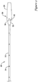
- FIG. 1 illustrates an example stent delivery system 10.
- System 10 may include an elongate shaft 12 and a handle 14 coupled to shaft 12.
- system 10 may be used to deliver a suitable stent, graft, endoprosthesis or the like to an area of interest within a body lumen of a patient.
- the body lumen may be a blood vessel located near the heart (e.g., within or near a cardiac vessel), within a peripheral vessel, within a neurological vessel, or at any other suitable location.
- Deployment of the stent may include the proximal retraction of a retraction sheath 16, which overlies the stent.
- Retraction of sheath 16 may include the actuation of an actuation member 18 generally disposed at handle 14.
- actuation member 18 is a thumbwheel that can be rotated by a clinician in order to accomplish proximal retraction of deployment sheath 16. Numerous other actuation members are contemplated. A number of other structures and features of system 10 can be seen in Figure 1 and are labeled with reference numbers. Additional discussion of these structures can be found below.
- Figures 2-6 illustrate at least some of the structural components that may be included as a part of system 10.
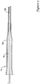
- system 10 may include an inner shaft or member 20 as illustrated in Figure 2 .
- inner member 20 may be a tubular structure and, thus, may include a lumen (not shown).
- the lumen may be a guidewire lumen that extends along at least a portion of the length of inner member 20. Accordingly, system 10 may be advanced over a guidewire to the desired target location in the vasculature.
- the lumen may be a perfusion/aspiration lumen that allows portions, components, or all of system 10 to be flushed, perfused, aspirated, or the like.
- Inner member 20 may include a stent receiving region 22 about which a stent (not shown, can be seen in Figures 3-4 ) may be disposed.
- the length and/or configuration of stent receiving region 22 may vary.
- stent receiving region 22 may have a length sufficient for the stent to be disposed thereon. It can be appreciated that as the length of the stent utilized for system 10 increases, the length of stent receiving region 22 also increases.
- Ports 24 may extend through the wall of inner member 20 such that fluid may be infused through the lumen of inner member 20 and may be flushed through ports 24. This may be desirable for a number of reasons. For example, ports 24 may allow a clinician to evacuate air bubbles that may be trapped adjacent the stent by perfusing fluid through ports 24. In addition, ports 24 may be used to aspirate fluid that may be disposed along inner member 20. Ports 24 may also aid in sterilization and/or other preparatory processing steps that may be involved in preparing system 10 for use.
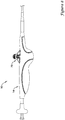
- a tip 26 may be attached to or otherwise disposed at the distal end of inner member 20.
- Tip 26 may generally have a rounded or smooth shape that provides a generally atraumatic distal end to system 10.
- tip 26 may have a smooth tapered distal portion 28 that gently tapers.
- Tip may also include a proximal ridge 30 that is configured so that sheath 16 can abut therewith.
- Tip 26 may also include a tapered proximal portion 33. Numerous other shapes and/or configurations are contemplated for tip 26.
- Tip 26 may also include one or more cutouts or flats 32 formed therein.
- flats 32 are understood to be cutouts or flattened portions of tip 26 where the outer dimension or profile of tip 26 is reduced.
- the name "flats” comes from the fact that these regions may have a somewhat “flat” appearance when compared to the remainder of tip 26, which generally may have a rounded profile.
- the shape, however, of flats 32 is not meant to be limited to being flat or planar as numerous shapes are contemplated.
- Flats 32 may allow for a gap or space to be defined between inner member 20 and deployment sheath 16 when sheath 16 abuts proximal ridge 30 of tip 26. This gap may allow for fluid, for example perfusion fluid passed through ports 24, to flow out from sheath 16. Thus, flats 32 may be used in conjunction with ports 24 to allow portions or all of system 10 to be flushed or otherwise evacuated of air bubbles.
- Figure 3 illustrates inner member 20 with some additional structure of system 10.
- a stent 34 is disposed about inner member 20 (e.g., about stent receiving region 22 of inner member 20).
- stent 34 is a self-expanding stent. Accordingly, stent 34 may be biased to outwardly expand. Because of this, stent 34 may not be "loaded onto" inner member 20 in a strict sense but rather may be thought of as being disposed about or surrounding inner member 20. Stent 34 may then be restrained within deployment sheath 16. In alternative embodiments, however, stent 34 may be directly loaded onto inner member 20 via crimping or any other suitable mechanical holding mechanism.
- An intermediate tube 36 may also be disposed over inner member 20.
- intermediate tube 36 may extend from a position adjacent to the proximal end of inner member 20 to a position proximal of the distal end of inner member 20.
- Intermediate tube 36 may include a bumper 38.
- bumper 38 may function by preventing any unwanted proximal movement of stent 38 during navigation and/or deployment of stent 38.
- Bumper 38 may have any suitable form.
- bumper 38 may be defined by a relatively short tube or sleeve that is disposed about intermediate tube 36.
- the material utilized for the sleeve may be the same or different from that of intermediate tube 36.
- Intermediate tube 36 may have a tapered or otherwise smooth transition in outer diameter adjacent bumper 38.
- polymeric material may be disposed or reflowed adjacent bumper 38 (which may include disposing the polymeric material about a portion or all of bumper 38) so as to define a gentle transition in outer diameter at bumper 38.
- Other configurations are contemplated and may be utilized in alternative embodiments.
- Figure 4 illustrates additional structure of system 10.
- deployment sheath 16 can be seen disposed over inner member 20, intermediate tube 36, and stent 34.
- sheath 16 is configured to shift between a first position, for example as shown in Figure 4 , where sheath 16 overlies stent 34 and a second position where sheath 16 is proximally retracted to a position substantially proximal of stent 34.
- first position may be utilized during navigation of system 10 to the appropriate location within a body lumen and the second position may be used to deploy stent 34.
- Sheath 16 may include a flared portion 40 where the outer diameter of sheath 16 is increased. In portion 40, the thickness of the tubular wall of sheath 16 may or may not be increased. Flared portion 40 may be desirable for a number of reasons. For example, flared portion 40 may allow sheath 16 to have an adequate inner dimension that is suitable so that sheath 16 may be disposed about stent 34 and bumper 38.
- sheath 16 may include a reinforcing member 42 embedded or otherwise included therewith.
- Reinforcing member 42 may have any number of a variety of different configurations.
- reinforcing member 42 may include a braid, coil, mesh, combinations thereof, or the like, or any other suitable configuration.
- reinforcing member 42 may extend along the entire length of sheath 16. In other embodiments, reinforcing member 42 may extend along one or more portions of the length of sheath 16. For example, reinforcing member 42 may extend along flared portion 40.
- Sheath 16 may also include a radiopaque marker or band 44.
- marker band 44 may be disposed adjacent to the distal end 46 of sheath 16.
- One or more additional marker bands 44 may be disposed along other portions of sheath 16 or other portions of system 10. Marker band 44 may allow the distal end 46 of sheath 16 to be fluoroscopically visualized during advancement of system 10 and/or deployment of stent 34.
- Figure 4 also illustrates the distal end 46 of sheath 16 abutting proximal ridge 30.
- stent 34 can be flushed (e.g., to remove air bubbles) by infusing fluid through inner member 20 and through ports 24. Because of flats 32, fluid may be allowed to be flushed out of sheath 16 by passing through the gaps formed between inner member 20 and sheath 16 at flats 32.
- Figure 5 illustrates a distal portion 48 of handle 14.
- handle 14 is attached to an outer member 50.
- Outer member 50 may be disposed about sheath 16 and extend along a portion of the length of sheath 16.
- system 10 may include four tubular structures that may be coaxially arranged - namely outer member 50, deployment sheath 16, intermediate tube 36, and inner member 20.
- outer member 50 may provide system 10 with a number of desirable benefits.
- outer member 50 may include or otherwise be formed from a lubricious material that can reduce friction that may be associated with proximally retracting sheath 16.
- outer member 50 may comprise a surface that can be clamped or otherwise locked so that the position of system 10 can be maintained without negatively impacting the retraction of sheath 16 (which might otherwise be impacted if sheath 16 was to be clamped). Numerous other desirable benefits may also be achieved through the use of outer member 50.
- Sheath 16 may pass proximally through outer member 50 and extend proximally back within handle 14. Intermediate tube 36 and inner member 20 both also extend back within handle 14 and are disposed within sheath 16.
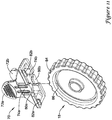
- the proximal end of sheath 16 may be attached to a gear rack assembly 52 with a fastener or clip 54 as illustrated in Figure 6 .
- Gear rack assembly 52 may include a plurality of teeth or gears 56. In practice, teeth 56 may be configured to engage with corresponding teeth or gears (not shown) on thumbwheel 18.
- thumbwheel 18 via gearing thereof with gears 56, can be utilized to proximally retract gear rack assembly 52 and, thus, sheath 16.
- Other structural arrangements may be utilized to accomplish proximal retraction of gear rack assembly 52 through the actuation of thumbwheel 18 or any other suitable actuation member.
- Gear rack assembly 52 may also include a flared proximal end 58. When properly assembly, the main body of gear rack assembly 52 may be disposed within handle 14 and proximal end 58 may be disposed along the exterior of handle 14. Gear rack assembly 52 may have a slot or groove 68 formed therein (not shown in Figure 6 , can be seen in Figure 7 ). Groove 68 may extend the length of gear rack assembly 52, including extending along proximal end 58.
- proximal end 58 may be generally located near the proximal end of inner member 20, the flared shape of proximal end 58 and the orientation of groove 68 may allow proximal end 58 to function as a guidewire introducer or funnel that may assist a clinician in placing, holding, removing, and/or exchanging a guidewire extending through inner member 20.
- intermediate tube 36 may need to be configured so as to provide the desired longitudinal support necessary to limit proximal movement of stent 34.
- clip member 60 is disposed within handle 14 and is configured to be secured along the interior of handle 14. Accordingly, clip member 60 allows the longitudinal position of one or more portions of system 10 to be fixed relative to handle 14.
- clip member 60 may include one or more fasteners or legs 62a/62b.
- handle 14 may have one or more slots, grooves, openings, or the like that are configured to seat legs 62a/62b such that the relative position of clip member 60 relative to handle 14 is fixed.
- clip member 60 may be configured to "snap in" to handle 14. This may desirably simplify manufacturing.
- clip member 60 is such that it is positioned near one or more structures of system 10.
- Clip member 60 is configured so that at least a portion thereof is positioned within groove 68 of gear rack assembly 52. This desirably places clip member 60 near inner member 20 and intermediate tube 36 (which may also extend through groove 68) such that clip member 60 can be associated therewith.
- clip member 60 may aid in maintaining the relative position of one or more structures of system 10 so that stent 34 can be accurately deployed.
- clip member 60 may include one or more tubular portions that inner member 20 may pass through and inner member 20 may optionally include a flared proximal end 66 that may substantially prevent inner member 20 from moving distally beyond the tubular portion(s).
- clip member 60 may include a flared region or end (not shown), which may facilitate entry of a guidewire into clip member and/or inner member 20.
- thumbwheel 18 When stent 34 is deployed, a clinician may actuate the actuation thumbwheel 18. Because of the association of thumbwheel 18 with gear rack assembly 52, relative rotation of thumbwheel 18 causes proximal movement of deployment sheath 16. As deployment sheath 16 proximally retracts, stent 34 is "uncovered” and (if stent 34 is a self-expanding stent) can expand within the body lumen.
- the actuation mechanism of a stent delivery system is set so that once deployment commences, it cannot be reversed.
- the system may be designed so that once the deployment sheath begins retracting, it cannot be reversed (e.g., it cannot be advanced in the distal direction). This may be desirable for a number of reasons. For example, if a stent begins to deploy and a clinician attempts to "recapture" the stent by distally advancing the deployment sheath, the sheath and/or other components of the delivery system may distort or alter the stent, which may reduce the effectiveness of the stent or otherwise may result in undesirable complications. In addition, any unwanted shifting the actuation mechanism during packaging, shipping, or storage of the delivery system may shift the position of the deployment sheath and, thus, may make the system no longer suitable for use.
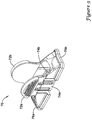
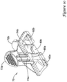
- System 10 may include a locking member or mechanism 70 as shown in Figure 8 .
- locking member 70 is configured to prevent any unwanted actuation of actuation member 18.
- locking member 70 may attach to or otherwise be coupled with actuation member 18. In doing so, locking member 70 may prevent rotation of actuation member 18 (e.g., when actuation member 18 takes the form of a thumbwheel).
- Attaching locking member 70 may include positioning locking member 70 near and/or in contact with handle 14.
- locking member 70 may make actuation member 18 generally inaccessible to a clinician so that undesired actuation thereof can be prevented.
- the forces required to "override" locking member 70 e.g., such that actuation member 18 may be moved
- locking member 70 can efficiently reduce and/or prevent undesired movement of deployment sheath 16 including during navigation of system 10 through the vasculature.
- locking member 70 may also provide significant resistance if a clinician should, for example inadvertently, pull on flared proximal end 58 (which might otherwise result in proximal retraction of deployment sheath 16).
- locking member 70 may help or otherwise prevent undesired movement of deployment sheath 16 that may result from proximal retraction of flared proximal end 58.
- locking member 70 may include one or more depressible tabs 72a/72b.
- locking member 70 includes a pair of depressible tabs 72a/72b.
- any suitable number of depressible tabs may be utilized.
- Locking member 70 may also include one or more gripping members or fingers 74a/74b. Again, in this example locking member 70 includes a pair of gripping fingers 74a/74b but any suitable number of depressible tabs may be utilized.
- each of the depressible tabs e.g., tab 72a
- a gripping finger e.g., gripping finger 74a
- the corresponding gripping finger e.g., gripping finger 74a
- the same may also be true of other tabs and/or gripping fingers.
- locking member 70 may be releasable "locked” onto or otherwise associated with or coupled to system 10, for example at handle 14.
- a clinician may squeeze or otherwise depress tabs 72a/72b so that they move inward.
- gripping fingers 74a/74b may be coupled to tabs 72/72b, depressing tabs 72a/72b may "open” or otherwise widen gripping fingers 74a/74b so that they can be fitted over actuation member 18.
- gripping fingers 74a/74b are in the "open” configuration, locking member 70 may be fitted over actuation member 18.
- gripping fingers 74a/74b may be biased to extend radially inward, releasing tabs 72a/72b may allow gripping fingers 74a/74b to move inward so as to secure locking member 70 onto actuation member 18.
- tabs 72a/72b and gripping fingers 74a/74b may also be understood as the locking member 70 having a grip portion (e.g., at or near gripping fingers 74a/74b) for attaching to locking member 70 to actuation member 18 and a handle portion (e.g., at or near tabs 72a/72b).
- the grip portion may be configured to shift between an attached configuration where locking member 70 is or can be attached to actuation member 18 and a released configuration where locking member 70 is or can be removed from actuation member 18.
- gripping fingers 74a/74b may be biased to extend radially inward
- applying a radially inward force to depressible tabs 72a/72b may shift the position of gripping fingers 74a/74b (e.g., outward) so that the grip portion shifts from the attached configuration to the released configuration.
- Removing the radially inward force from depressible tabs 72a/72b may allow the bias of gripping fingers 74a/74b to shift gripping fingers 74a/74b inward so that the grip portion shifts from the released configuration to the attached configuration.
- Releasing locking member 70 from actuation member 18 may include similar steps (e.g., depressing tabs 72a/72b to open gripping fingers 74a/74b and removing locking member 70 from actuation member 18).
- Locking member 70 may include additional features which further aid in securing locking member 70 with actuation member 18 and/or handle 14.
- Figure 9 additionally illustrates that locking member 70 includes a first or proximal edge 76a and a second or distal edge 76b. Edges 76a/76b are generally configured so that the lay directly over or onto handle 14. Thus, any rotary forces applied to locking member 70 will encounter interference between one or more of edges 76a/76b and the surface of handle 14.
- FIG 10 illustrates that gripping fingers 74a74b may each include an inward-extending tab, for example tabs 80a/80b.
- actuation member 18 may include an outer rim or flanged portion 84 and an inner portion 86 that is inset relative to rim 84 as illustrated in Figure 11 , tabs 80a/80b may fit over rim 84 and engage inner portion 86. This may create additional structural interference that is designed to reduce the possibility of removing locking member 70 from actuation member 18 at times other than those desired by the clinician.
- locking member 70 may include one or more projections, for example projections 82a/82b. Because one or more channels may be formed in handle 14 adjacent to actuation member 18, for example channels 88a/88b as shown in Figure 12 , projections 82a/82b may be configured to extend into channels 88a/88b. This may create additional structural interference that is designed to reduce the possibility of rotating or otherwise moving actuation member 18 at times other than those desired by the clinician.
- locking member 70 may made from a material that is able to adequately transfer force from the "top” (e.g., adjacent tabs 72a/72b) to the "bottom” (e.g., adjacent fingers 74a/74b) of locking member 70.
- the material used for locking member 70 may be selected so that locking member 70 can withstand multiple lock/unlock cycles, require a relatively low finger force to deflect tabs 72a/72b, be not too brittle or ductile, have a minimum of about 5% strain at yield, and have a relatively high flexural modulus. These are just examples.
- locking member 70 includes a thermoplastic material with a relatively high percent strain at yield and a relatively high flexural modulus yet with a good balance between brittle and ductile properties so as to allow locking member to be actuated without breaking or otherwise being damaged.
- locking member 70 may include a polyamide such as GRILAMID® TR55-LX available from EMS American Grilon.
- Other materials are contemplated including, for example, acrylonitrile butadiene styrene (ABS), an ABS/polycarbonate blend, polyamide, polyethersulfone, polyphenylsulfone, or any other suitable material including those disclosed herein.
- the materials that can be used for the various components of system 10 may include those commonly associated with medical devices.
- the following discussion makes reference to shaft 12, deployment sheath 16, and inner member 20.
- this is not intended to limit the invention as the discussion may be applied to other similar members and/or components of members or systems disclosed herein.
- Shaft 12, deployment sheath 16, and inner member 20, and/or other components of system 10 may be made from a metal, metal alloy, polymer (some examples of which are disclosed below), a metal-polymer composite, combinations thereof, and the like, or any other suitable material.
- suitable metals and metal alloys include stainless steel, such as 304V, 304L, and 316LV stainless steel; mild steel; nickel-titanium alloy such as linear-elastic and/or super-elastic nitinol; other nickel alloys such as nickel-chromium-molybdenum alloys (e.g., UNS: N06625 such as INCONEL® 625, UNS: N06022 such as HASTELLOY® C-22®, UNS: N10276 such as HASTELLOY® C276®, other HASTELLOY® alloys, and the like), nickel-copper alloys (e.g., UNS: N04400 such as MONEL® 400, NICKELVAC® 400, NICORROS® 400, and the like), nickcl-cobalt-chromium-molybdenum alloys (e.g., UNS: R30035 such as MP35-N® and the like), nickel-molybdenum alloys (
- Linear elastic and/or non-super-elastic nitinol may be distinguished from super elastic nitinol in that the linear elastic and/or non-super-elastic nitinol does not display a substantial "superelastic plateau” or “flag region” in its stress/strain curve like super elastic nitinol does.
- linear elastic and/or non-super-elastic nitinol as recoverable strain increases, the stress continues to increase in a substantially linear, or a somewhat, but not necessarily entirely linear relationship until plastic deformation begins or at least in a relationship that is more linear that the super elastic plateau and/or flag region that may be seen with super clastic nitinol.
- linear elastic and/or non-super-elastic nitinol may also be termed "substantially" linear elastic and/or non-super-elastic nitinol.
- linear elastic and/or non-super-elastic nitinol may also be distinguishable from super elastic nitinol in that linear elastic and/or non-super-elastic nitinol may accept up to about 2-5% strain while remaining substantially elastic (e.g., before plastically deforming) whereas super elastic nitinol may accept up to about 8% strain before plastically deforming. Both of these materials can be distinguished from other linear elastic materials such as stainless steel (that can also can be distinguished based on its composition), which may accept only about 0.2-0.44% strain before plastically deforming.
- the linear elastic and/or non-super-elastic nickel-titanium alloy is an alloy that does not show any martensite/austenite phase changes that are detectable by DSC and DMTA analysis over a large temperature range.
- the mechanical bending properties of such material may therefore be generally inert to the effect of temperature over this very broad range of temperature.
- the mechanical bending properties of the linear elastic and/or non-super-elastic nickel-titanium alloy at ambient or room temperature are substantially the same as the mechanical properties at body temperature, for example, in that they do not display a super-elastic plateau and/or flag region.
- the linear elastic and/or non-super-elastic nickel-titanium alloy maintains its linear elastic and/or non-super-elastic characteristics and/or properties and has essentially no yield point.
- the linear elastic and/or non-super-elastic nickel-titanium alloy may be in the range of about 50 to about 60 weight percent nickel, with the remainder being essentially titanium. In some embodiments, the composition is in the range of about 54 to about 57 weight percent nickel.
- a suitable nickel-titanium alloy is FHP-NT alloy commercially available from Furukawa Techno Material Co. of Kanagawa, Japan. Some examples of nickel titanium alloys are disclosed in U.S. Patent Nos. 5,238,004 and 6,508,803 . Other suitable materials may include ULTANIUMTM (available from Neo-Metrics) and GUM METALTM (available from Toyota).
- a superelastic alloy for example a superelastic nitinol can be used to achieve desired properties.
- portions or all of shaft 12, deployment sheath 16, and inner member 20 may also be doped with, made of, or otherwise include a radiopaque material including those listed herein or other suitable radiopaque materials.
- a degree of MRI compatibility is imparted into system 10.
- shaft 12, deployment sheath 16, and inner member 20, in a manner that would impart a degree of MRI compatibility may be desirable to make shaft 12, deployment sheath 16, and inner member 20, in a manner that would impart a degree of MRI compatibility.
- shaft 12, deployment sheath 16, and inner member 20, or portions thereof may be made of a material that does not substantially distort the image and create substantial artifacts (artifacts are gaps in the image). Certain ferromagnetic materials, for example, may not be suitable because they may create artifacts in an MRI image.
- Shaft 12, deployment sheath 16, and inner member 20, or portions thereof may also be made from a material that the MRI machine can image.
- Some materials that exhibit these characteristics include, for example, tungsten, cobalt-chromium-molybdenum alloys (e.g., UNS: R30003 such as ELGILOY®, PHYNOX®, and the like), nickel-cobalt-chromium-molybdenum alloys (e.g., UNS: R30035 such as MP35-N® and the like), nitinol, and the like, and others.
- cobalt-chromium-molybdenum alloys e.g., UNS: R30003 such as ELGILOY®, PHYNOX®, and the like
- nickel-cobalt-chromium-molybdenum alloys e.g., UNS: R30035 such as MP35-N® and the like
- nitinol and the like, and others.
- suitable polymers that may be used to form shaft 12, deployment sheath 16, and inner member 20, and/or other components of system 10 may include polytetrafluoroethylene (PTFE), ethylene tetrafluoroethylene (ETFE), fluorinated ethylene propylene (FEP), polyoxymethylene (POM, for example, DELRIN® available from DuPont), polyether block ester, polyurcthanc (for example, Polyurethane 85A), polypropylene (PP), polyvinylchloride (PVC), polyether-ester (for example, ARNITEL® available from DSM Engineering Plastics), ether or ester based copolymers (for example, butylene/poly(alkylene ether) phthalate and/or other polyester elastomers such as HYTREL® available from DuPont), polyamide (for example, DURETHAN® available from Bayer or CRISTAMID® available from Elf Atochem), elastomeric polyamides, block polyamide/ethers, poly(
- the exterior surface of the system 10 may include a coating, for example a lubricious, a hydrophilic, a protective, or other type of coating.
- Hydrophobic coatings such as fluoropolymers provide a dry lubricity which improves device handling and exchanges.
- Lubricious coatings improve steerability and improve lesion crossing capability.
- Suitable lubricious polymers may include silicone and the like, polymers such as high-density polyethylene (HDPE), polytetrafluoroethylene (PTFE), polyarylene oxides, polyvinylpyrolidones, polyvinylalcohols, hydroxy alkyl cellulosics, algins, saccharides, caprolactones, and the like, and mixtures and combinations thereof.
- Hydrophilic polymers may be blended among themselves or with formulated amounts of water insoluble compounds (including some polymers) to yield coatings with suitable lubricity, bonding, and solubility.
- Some other examples of such coatings and materials and methods used to create such coatings can be found in U.S. Patent Nos. 6,139,510 and 5,772,609 .
Description
- The present invention pertains to medical devices and methods for making and using medical devices. More particularly, the present invention pertains to stent delivery systems and locking members for use therewith.
- A wide variety of intracorporeal medical devices have been developed for medical use, for example, intravascular use. Some of these devices include stent delivery systems. These devices are manufactured by any one of a variety of different manufacturing methods and may be used according to any one of a variety of methods. Of the known stent delivery devices and methods for making and using the same, each has certain advantages and disadvantages. There is an ongoing need to provide alternative stent delivery devices as well as alternative methods for making and using stent delivery devices.
-
WO 00/78248 A1 -
WO 2008/118670 A2 relates to a catheter for delivering a prosthesis to a treatment site in a body lumen, the catheter comprising: an elongate flexible member having a proximal end and a distal end; a sheath slidably disposed over the elongate flexible member; a plurality of self-expanding tubular prostheses carried in axially spaced-apart locations along the elongate flexible member and within the sheath, the plurality of self- expanding tubular prostheses adapted to be selectively interlocked with one another and constrained by the sheath in a radially contracted configuration, the prostheses being separately releasable from the sheath as the sheath is retracted relative to the elongate flexible member; and a pusher member slidably disposed along the elongate flexible member within the sheath, the pusher member adapted to move past the prostheses in a first direction, while in a second direction the pusher member engages a selected prosthesis so as to move the prosthesis with the pusher member to interlock the selected prosthesis with a second prosthesis. - The present invention is defined by the claims.
- The invention provides design, material, manufacturing method, and use alternatives for stent delivery systems and locking members for preventing unwanted actuation of a actuation member on a stent delivery system. An example stent delivery system may include an inner member. A deployment sheath may be disposed about the inner member. A stent may be disposed between the inner member and the deployment sheath. A handle may be coupled to the inner member and to the deployment sheath. The handle may include an actuation member. The actuation member may be configured to shift the longitudinal position of the deployment sheath relative to the inner member. A locking member may be disposed on the actuation member. The locking member may be configured to prevent unwanted actuation of the actuation member.
- An example locking member for preventing unwanted actuation of a thumbwheel on a stent delivery system may include a body having a proximal edge and a distal edge. At least one of the proximal edge and the distal edge may be configured to engage a handle of the stent delivery system. One or more gripping fingers may be coupled to the body. The gripping fingers may be configured to engage the thumbwheel. The gripping fingers may be configured to shift between an engaged configuration where the gripping fingers are engaged with the thumbwheel and a released configuration where the gripping fingers are released from the thumbwheel. One or more depressible tabs may be coupled to the body for shifting the position of the gripping fingers.
- An example method for preventing unwanted motion of a thumbwheel on a stent delivery system may include providing a locking member. The locking member may include a body having a proximal edge and a distal edge. At least one of the proximal edge and the distal edge may be configured to engage a handle of the stent delivery system. One or more gripping fingers may be coupled to the body. The gripping fingers may be configured to engage the thumbwheel. The gripping fingers may be configured to shift between an engaged configuration where the gripping fingers are engaged with the thumbwheel and a released configuration where the gripping fingers are released from the thumbwheel. The gripping fingers may be biased to extend radially inward. One or more depressible tabs may be coupled to the body for shifting the position of the gripping fingers. The method may also include applying a radially inward force to the depressible tabs to shift the gripping fingers from the engaged configuration to the released configuration, disposing the locking member on the thumbwheel, and removing the radially inward force from the depressible tabs to shift the gripping fingers from the released configuration to the engaged configuration and to attach the locking member to the thumbwheel.
- The above summary of some embodiments is not intended to describe each disclosed embodiment or every implementation of the present invention. The Figures, and Detailed Description, which follow, more particularly exemplify these embodiments.
- The invention may be more completely understood in consideration of the following detailed description of various embodiments of the invention in connection with the accompanying drawings, in which:
-
Figure 1 is a partial cross-sectional side view of an example stent delivery system; -
Figure 2 is a side view of a portion of the example stent delivery system shown inFigure 1 ; -
Figure 3 is a side view of another portion of the example stent delivery system shown inFigure 1 ; -
Figure 4 is a side view of another portion of the example stent delivery system shown inFigure 1 ; -
Figure 5 is a side view of another portion of the example stent delivery system shown inFigure 1 ; -
Figure 6 is a side view of another portion of the example stent delivery system shown inFigure 1 ; -
Figure 7 is a perspective view of another portion of the example stent delivery system shown inFigure 1 ; -
Figure 8 is a side view of the example locking member shown engaged with a stent delivery system; -
Figure 9 is a perspective view of an example locking member for use with a stent delivery system; -
Figure 10 is a bottom view of the example locking member shown inFigure 9 ; -
Figure 11 is a plan view showing the association of the locking member with an actuation member of a stent delivery system; and -
Figure 12 is a plan view showing the association of the locking member with the handle of a stent delivery system. - While the invention is amenable to various modifications and alternative forms, specifics thereof have been shown by way of example in the drawings and will be described in detail. It should be understood, however, that the intention is not to limit the invention to the particular embodiments described. On the contrary, the intention is to cover all modifications, equivalents, and alternatives falling within the scope of the invention.
- For the following defined terms, these definitions shall be applied, unless a different definition is given in the claims or elsewhere in this specification.
- All numeric values are herein assumed to be modified by the term "about," whether or not explicitly indicated. The term "about" generally refers to a range of numbers that one of skill in the art would consider equivalent to the recited value (i.e., having the same function or result). In many instances, the terms "about" may include numbers that are rounded to the nearest significant figure.
- The recitation of numerical ranges by endpoints includes all numbers within that range (e.g. 1 to 5 includes 1, 1.5, 2, 2.75, 3, 3.80, 4, and 5).
- As used in this specification and the appended claims, the singular forms "a", "an", and "the" include plural referents unless the content clearly dictates otherwise. As used in this specification and the appended claims, the term "or" is generally employed in its sense including "and/or" unless the content clearly dictates otherwise.
- The following detailed description should be read with reference to the drawings in which similar elements in different drawings are numbered the same. The drawings, which are not necessarily to scale, depict illustrative embodiments and are not intended to limit the scope of the invention.
-
Figure 1 illustrates an examplestent delivery system 10.System 10 may include anelongate shaft 12 and ahandle 14 coupled toshaft 12. In general,system 10 may be used to deliver a suitable stent, graft, endoprosthesis or the like to an area of interest within a body lumen of a patient. The body lumen may be a blood vessel located near the heart (e.g., within or near a cardiac vessel), within a peripheral vessel, within a neurological vessel, or at any other suitable location. Deployment of the stent may include the proximal retraction of aretraction sheath 16, which overlies the stent. Retraction ofsheath 16 may include the actuation of anactuation member 18 generally disposed athandle 14. In the example illustrated inFigure 1 ,actuation member 18 is a thumbwheel that can be rotated by a clinician in order to accomplish proximal retraction ofdeployment sheath 16. Numerous other actuation members are contemplated. A number of other structures and features ofsystem 10 can be seen inFigure 1 and are labeled with reference numbers. Additional discussion of these structures can be found below. -
Figures 2-6 illustrate at least some of the structural components that may be included as a part ofsystem 10. For example,system 10 may include an inner shaft ormember 20 as illustrated inFigure 2 . In at least some embodiments,inner member 20 may be a tubular structure and, thus, may include a lumen (not shown). The lumen may be a guidewire lumen that extends along at least a portion of the length ofinner member 20. Accordingly,system 10 may be advanced over a guidewire to the desired target location in the vasculature. In addition, or in alternative embodiments, the lumen may be a perfusion/aspiration lumen that allows portions, components, or all ofsystem 10 to be flushed, perfused, aspirated, or the like. -
Inner member 20 may include astent receiving region 22 about which a stent (not shown, can be seen inFigures 3-4 ) may be disposed. The length and/or configuration ofstent receiving region 22 may vary. For example,stent receiving region 22 may have a length sufficient for the stent to be disposed thereon. It can be appreciated that as the length of the stent utilized forsystem 10 increases, the length ofstent receiving region 22 also increases. - Along or otherwise disposed adjacent
stent receiving region 22 may be one ormore perfusion ports 24.Ports 24 may extend through the wall ofinner member 20 such that fluid may be infused through the lumen ofinner member 20 and may be flushed throughports 24. This may be desirable for a number of reasons. For example,ports 24 may allow a clinician to evacuate air bubbles that may be trapped adjacent the stent by perfusing fluid throughports 24. In addition,ports 24 may be used to aspirate fluid that may be disposed alonginner member 20.Ports 24 may also aid in sterilization and/or other preparatory processing steps that may be involved in preparingsystem 10 for use. - A
tip 26 may be attached to or otherwise disposed at the distal end ofinner member 20.Tip 26 may generally have a rounded or smooth shape that provides a generally atraumatic distal end tosystem 10. For example,tip 26 may have a smooth tapereddistal portion 28 that gently tapers. Tip may also include aproximal ridge 30 that is configured so thatsheath 16 can abut therewith.Tip 26 may also include a taperedproximal portion 33. Numerous other shapes and/or configurations are contemplated fortip 26. -
Tip 26 may also include one or more cutouts orflats 32 formed therein. For the purposes of this disclosure,flats 32 are understood to be cutouts or flattened portions oftip 26 where the outer dimension or profile oftip 26 is reduced. The name "flats" comes from the fact that these regions may have a somewhat "flat" appearance when compared to the remainder oftip 26, which generally may have a rounded profile. The shape, however, offlats 32 is not meant to be limited to being flat or planar as numerous shapes are contemplated. -
Flats 32 may allow for a gap or space to be defined betweeninner member 20 anddeployment sheath 16 whensheath 16 abutsproximal ridge 30 oftip 26. This gap may allow for fluid, for example perfusion fluid passed throughports 24, to flow out fromsheath 16. Thus,flats 32 may be used in conjunction withports 24 to allow portions or all ofsystem 10 to be flushed or otherwise evacuated of air bubbles. -
Figure 3 illustratesinner member 20 with some additional structure ofsystem 10. In this figure, astent 34 is disposed about inner member 20 (e.g., aboutstent receiving region 22 of inner member 20). In some embodiments,stent 34 is a self-expanding stent. Accordingly,stent 34 may be biased to outwardly expand. Because of this,stent 34 may not be "loaded onto"inner member 20 in a strict sense but rather may be thought of as being disposed about or surroundinginner member 20.Stent 34 may then be restrained withindeployment sheath 16. In alternative embodiments, however,stent 34 may be directly loaded ontoinner member 20 via crimping or any other suitable mechanical holding mechanism. - An
intermediate tube 36 may also be disposed overinner member 20. In at least some embodiments,intermediate tube 36 may extend from a position adjacent to the proximal end ofinner member 20 to a position proximal of the distal end ofinner member 20.Intermediate tube 36 may include abumper 38. In practice,bumper 38 may function by preventing any unwanted proximal movement ofstent 38 during navigation and/or deployment ofstent 38. -
Bumper 38 may have any suitable form. In some embodiments,bumper 38 may be defined by a relatively short tube or sleeve that is disposed aboutintermediate tube 36. The material utilized for the sleeve may be the same or different from that ofintermediate tube 36.Intermediate tube 36 may have a tapered or otherwise smooth transition in outer diameteradjacent bumper 38. For example, polymeric material may be disposed or reflowed adjacent bumper 38 (which may include disposing the polymeric material about a portion or all of bumper 38) so as to define a gentle transition in outer diameter atbumper 38. Other configurations are contemplated and may be utilized in alternative embodiments. -
Figure 4 illustrates additional structure ofsystem 10. Heredeployment sheath 16 can be seen disposed overinner member 20,intermediate tube 36, andstent 34. It can be appreciated thatsheath 16 is configured to shift between a first position, for example as shown inFigure 4 , wheresheath 16 overliesstent 34 and a second position wheresheath 16 is proximally retracted to a position substantially proximal ofstent 34. In general, the first position may be utilized during navigation ofsystem 10 to the appropriate location within a body lumen and the second position may be used to deploystent 34. -
Sheath 16 may include a flaredportion 40 where the outer diameter ofsheath 16 is increased. Inportion 40, the thickness of the tubular wall ofsheath 16 may or may not be increased. Flaredportion 40 may be desirable for a number of reasons. For example, flaredportion 40 may allowsheath 16 to have an adequate inner dimension that is suitable so thatsheath 16 may be disposed aboutstent 34 andbumper 38. - In at least some embodiments,
sheath 16 may include a reinforcingmember 42 embedded or otherwise included therewith. Reinforcingmember 42 may have any number of a variety of different configurations. For example, reinforcingmember 42 may include a braid, coil, mesh, combinations thereof, or the like, or any other suitable configuration. In some embodiments, reinforcingmember 42 may extend along the entire length ofsheath 16. In other embodiments, reinforcingmember 42 may extend along one or more portions of the length ofsheath 16. For example, reinforcingmember 42 may extend along flaredportion 40. -
Sheath 16 may also include a radiopaque marker orband 44. In general,marker band 44 may be disposed adjacent to thedistal end 46 ofsheath 16. One or moreadditional marker bands 44 may be disposed along other portions ofsheath 16 or other portions ofsystem 10.Marker band 44 may allow thedistal end 46 ofsheath 16 to be fluoroscopically visualized during advancement ofsystem 10 and/or deployment ofstent 34. -
Figure 4 also illustrates thedistal end 46 ofsheath 16 abuttingproximal ridge 30. In this configuration,stent 34 can be flushed (e.g., to remove air bubbles) by infusing fluid throughinner member 20 and throughports 24. Because offlats 32, fluid may be allowed to be flushed out ofsheath 16 by passing through the gaps formed betweeninner member 20 andsheath 16 atflats 32. -
Figure 5 illustrates adistal portion 48 ofhandle 14. Here it can be seen that handle 14 is attached to anouter member 50.Outer member 50 may be disposed aboutsheath 16 and extend along a portion of the length ofsheath 16. Thus, along at least a portion of the length ofsystem 10,system 10 may include four tubular structures that may be coaxially arranged - namelyouter member 50,deployment sheath 16,intermediate tube 36, andinner member 20. In at least some embodiments,outer member 50 may providesystem 10 with a number of desirable benefits. For example,outer member 50 may include or otherwise be formed from a lubricious material that can reduce friction that may be associated with proximally retractingsheath 16. In addition,outer member 50 may comprise a surface that can be clamped or otherwise locked so that the position ofsystem 10 can be maintained without negatively impacting the retraction of sheath 16 (which might otherwise be impacted ifsheath 16 was to be clamped). Numerous other desirable benefits may also be achieved through the use ofouter member 50. -
Sheath 16 may pass proximally throughouter member 50 and extend proximally back withinhandle 14.Intermediate tube 36 andinner member 20 both also extend back withinhandle 14 and are disposed withinsheath 16. The proximal end ofsheath 16 may be attached to agear rack assembly 52 with a fastener orclip 54 as illustrated inFigure 6 . Thus, it can be appreciated that proximal movement ofgear rack assembly 52 may result in analogous proximal movement ofdeployment sheath 14.Gear rack assembly 52 may include a plurality of teeth or gears 56. In practice,teeth 56 may be configured to engage with corresponding teeth or gears (not shown) onthumbwheel 18. Consequently, rotation ofthumbwheel 18, via gearing thereof withgears 56, can be utilized to proximally retractgear rack assembly 52 and, thus,sheath 16. Other structural arrangements may be utilized to accomplish proximal retraction ofgear rack assembly 52 through the actuation ofthumbwheel 18 or any other suitable actuation member. -
Gear rack assembly 52 may also include a flaredproximal end 58. When properly assembly, the main body ofgear rack assembly 52 may be disposed withinhandle 14 andproximal end 58 may be disposed along the exterior ofhandle 14.Gear rack assembly 52 may have a slot or groove 68 formed therein (not shown inFigure 6 , can be seen inFigure 7 ).Groove 68 may extend the length ofgear rack assembly 52, including extending alongproximal end 58. Becauseproximal end 58 may be generally located near the proximal end ofinner member 20, the flared shape ofproximal end 58 and the orientation ofgroove 68 may allowproximal end 58 to function as a guidewire introducer or funnel that may assist a clinician in placing, holding, removing, and/or exchanging a guidewire extending throughinner member 20. - In order to properly deploy
stent 34, the various components ofsystem 10 may need to work in concert so that relative motion ofsheath 16 can be accomplished relative toinner member 20. In addition, to improve the accuracy of deployment,intermediate tube 36 may need to be configured so as to provide the desired longitudinal support necessary to limit proximal movement ofstent 34. - The proper configuration of these structures is maintained through the use of a
clip member 60 as illustrated inFigure 7 . - In general,
clip member 60 is disposed withinhandle 14 and is configured to be secured along the interior ofhandle 14. Accordingly,clip member 60 allows the longitudinal position of one or more portions ofsystem 10 to be fixed relative to handle 14. In order to secureclip member 60 to handle 14,clip member 60 may include one or more fasteners orlegs 62a/62b. For example, handle 14 may have one or more slots, grooves, openings, or the like that are configured to seatlegs 62a/62b such that the relative position ofclip member 60 relative to handle 14 is fixed. In some embodiments,clip member 60 may be configured to "snap in" to handle 14. This may desirably simplify manufacturing. - The orientation of
clip member 60 is such that it is positioned near one or more structures ofsystem 10.Clip member 60 is configured so that at least a portion thereof is positioned withingroove 68 ofgear rack assembly 52. This desirably placesclip member 60 nearinner member 20 and intermediate tube 36 (which may also extend through groove 68) such thatclip member 60 can be associated therewith. As such,clip member 60 may aid in maintaining the relative position of one or more structures ofsystem 10 so thatstent 34 can be accurately deployed. For example,clip member 60 may include one or more tubular portions thatinner member 20 may pass through andinner member 20 may optionally include a flaredproximal end 66 that may substantially preventinner member 20 from moving distally beyond the tubular portion(s). In some embodiments,clip member 60 may include a flared region or end (not shown), which may facilitate entry of a guidewire into clip member and/orinner member 20. - When
stent 34 is deployed, a clinician may actuate theactuation thumbwheel 18. Because of the association ofthumbwheel 18 withgear rack assembly 52, relative rotation ofthumbwheel 18 causes proximal movement ofdeployment sheath 16. Asdeployment sheath 16 proximally retracts,stent 34 is "uncovered" and (ifstent 34 is a self-expanding stent) can expand within the body lumen. - Often times, the actuation mechanism of a stent delivery system is set so that once deployment commences, it cannot be reversed. In other words, the system may be designed so that once the deployment sheath begins retracting, it cannot be reversed (e.g., it cannot be advanced in the distal direction). This may be desirable for a number of reasons. For example, if a stent begins to deploy and a clinician attempts to "recapture" the stent by distally advancing the deployment sheath, the sheath and/or other components of the delivery system may distort or alter the stent, which may reduce the effectiveness of the stent or otherwise may result in undesirable complications. In addition, any unwanted shifting the actuation mechanism during packaging, shipping, or storage of the delivery system may shift the position of the deployment sheath and, thus, may make the system no longer suitable for use.
-
System 10 may include a locking member ormechanism 70 as shown inFigure 8 . In general, lockingmember 70 is configured to prevent any unwanted actuation ofactuation member 18. In at least some embodiments, lockingmember 70 may attach to or otherwise be coupled withactuation member 18. In doing so, lockingmember 70 may prevent rotation of actuation member 18 (e.g., whenactuation member 18 takes the form of a thumbwheel). Attaching lockingmember 70 may include positioning lockingmember 70 near and/or in contact withhandle 14. Some additional details regarding some of the arrangements contemplated for the positioning of lockingmember 70 relative toactuation member 18 and/or handle 14 are discussed in more detail below. - As can be appreciated, locking
member 70 may makeactuation member 18 generally inaccessible to a clinician so that undesired actuation thereof can be prevented. In general, the forces required to "override" locking member 70 (e.g., such thatactuation member 18 may be moved) may be significantly higher than the forces acting onsystem 10 during handling and/or insertion ofsystem 10 into a patient. Thus, lockingmember 70 can efficiently reduce and/or prevent undesired movement ofdeployment sheath 16 including during navigation ofsystem 10 through the vasculature. In addition, in embodiments whereactuation member 18 takes the form of a thumbwheel, and becausegear rack assembly 52 may be coupled tothumbwheel 18, lockingmember 70 may also provide significant resistance if a clinician should, for example inadvertently, pull on flared proximal end 58 (which might otherwise result in proximal retraction of deployment sheath 16). Thus, lockingmember 70 may help or otherwise prevent undesired movement ofdeployment sheath 16 that may result from proximal retraction of flaredproximal end 58. -
Figure 9 illustrates lockingmember 70 and shows some additional structural features thereof. For example, lockingmember 70 may include one or moredepressible tabs 72a/72b. In thisexample locking member 70 includes a pair ofdepressible tabs 72a/72b. However, any suitable number of depressible tabs may be utilized. Lockingmember 70 may also include one or more gripping members orfingers 74a/74b. Again, in thisexample locking member 70 includes a pair ofgripping fingers 74a/74b but any suitable number of depressible tabs may be utilized. In at least some embodiments, each of the depressible tabs (e.g.,tab 72a) is associated with a gripping finger (e.g., grippingfinger 74a). Thus, if one of the depressible tabs (e.g.,tab 72a) is moved, for example pressed so as to movetab 72a inward, the corresponding gripping finger (e.g., grippingfinger 74a) also moves (e.g., outward). The same may also be true of other tabs and/or gripping fingers. - In use, locking
member 70 may be releasable "locked" onto or otherwise associated with or coupled tosystem 10, for example athandle 14. To do so, a clinician may squeeze or otherwise depresstabs 72a/72b so that they move inward. Because grippingfingers 74a/74b may be coupled to tabs 72/72b,depressing tabs 72a/72b may "open" or otherwise widengripping fingers 74a/74b so that they can be fitted overactuation member 18. Thus, when grippingfingers 74a/74b are in the "open" configuration, lockingmember 70 may be fitted overactuation member 18. Because grippingfingers 74a/74b may be biased to extend radially inward, releasingtabs 72a/72b may allowgripping fingers 74a/74b to move inward so as to secure lockingmember 70 ontoactuation member 18. - The arrangement of
tabs 72a/72b andgripping fingers 74a/74b may also be understood as the lockingmember 70 having a grip portion (e.g., at or near grippingfingers 74a/74b) for attaching to lockingmember 70 toactuation member 18 and a handle portion (e.g., at ornear tabs 72a/72b). The grip portion may be configured to shift between an attached configuration where lockingmember 70 is or can be attached toactuation member 18 and a released configuration where lockingmember 70 is or can be removed fromactuation member 18. Because grippingfingers 74a/74b may be biased to extend radially inward, applying a radially inward force todepressible tabs 72a/72b may shift the position ofgripping fingers 74a/74b (e.g., outward) so that the grip portion shifts from the attached configuration to the released configuration. Removing the radially inward force fromdepressible tabs 72a/72b may allow the bias ofgripping fingers 74a/74b to shiftgripping fingers 74a/74b inward so that the grip portion shifts from the released configuration to the attached configuration. Releasing lockingmember 70 fromactuation member 18 may include similar steps (e.g.,depressing tabs 72a/72b to opengripping fingers 74a/74b and removing lockingmember 70 from actuation member 18). - Locking
member 70 may include additional features which further aid in securing lockingmember 70 withactuation member 18 and/or handle 14. For example,Figure 9 additionally illustrates that lockingmember 70 includes a first orproximal edge 76a and a second ordistal edge 76b.Edges 76a/76b are generally configured so that the lay directly over or ontohandle 14. Thus, any rotary forces applied to lockingmember 70 will encounter interference between one or more ofedges 76a/76b and the surface ofhandle 14. - In addition,
Figure 10 illustrates that gripping fingers 74a74b may each include an inward-extending tab, forexample tabs 80a/80b. Becauseactuation member 18 may include an outer rim orflanged portion 84 and aninner portion 86 that is inset relative torim 84 as illustrated inFigure 11 ,tabs 80a/80b may fit overrim 84 and engageinner portion 86. This may create additional structural interference that is designed to reduce the possibility of removing lockingmember 70 fromactuation member 18 at times other than those desired by the clinician. -
Figure 10 also illustrates that lockingmember 70 may include one or more projections, forexample projections 82a/82b. Because one or more channels may be formed inhandle 14 adjacent toactuation member 18, forexample channels 88a/88b as shown inFigure 12 ,projections 82a/82b may be configured to extend intochannels 88a/88b. This may create additional structural interference that is designed to reduce the possibility of rotating or otherwise movingactuation member 18 at times other than those desired by the clinician. - In at least some embodiments, locking
member 70 may made from a material that is able to adequately transfer force from the "top" (e.g.,adjacent tabs 72a/72b) to the "bottom" (e.g.,adjacent fingers 74a/74b) of lockingmember 70. In addition, the material used for lockingmember 70 may be selected so that lockingmember 70 can withstand multiple lock/unlock cycles, require a relatively low finger force to deflecttabs 72a/72b, be not too brittle or ductile, have a minimum of about 5% strain at yield, and have a relatively high flexural modulus. These are just examples. In at least some embodiments, lockingmember 70 includes a thermoplastic material with a relatively high percent strain at yield and a relatively high flexural modulus yet with a good balance between brittle and ductile properties so as to allow locking member to be actuated without breaking or otherwise being damaged. For example, lockingmember 70 may include a polyamide such as GRILAMID® TR55-LX available from EMS American Grilon. Other materials, however, are contemplated including, for example, acrylonitrile butadiene styrene (ABS), an ABS/polycarbonate blend, polyamide, polyethersulfone, polyphenylsulfone, or any other suitable material including those disclosed herein. - The materials that can be used for the various components of system 10 (and/or other systems disclosed herein) may include those commonly associated with medical devices. For simplicity purposes, the following discussion makes reference to
shaft 12,deployment sheath 16, andinner member 20. However, this is not intended to limit the invention as the discussion may be applied to other similar members and/or components of members or systems disclosed herein. -
Shaft 12,deployment sheath 16, andinner member 20, and/or other components ofsystem 10 may be made from a metal, metal alloy, polymer (some examples of which are disclosed below), a metal-polymer composite, combinations thereof, and the like, or any other suitable material. Some examples of suitable metals and metal alloys include stainless steel, such as 304V, 304L, and 316LV stainless steel; mild steel; nickel-titanium alloy such as linear-elastic and/or super-elastic nitinol; other nickel alloys such as nickel-chromium-molybdenum alloys (e.g., UNS: N06625 such as INCONEL® 625, UNS: N06022 such as HASTELLOY® C-22®, UNS: N10276 such as HASTELLOY® C276®, other HASTELLOY® alloys, and the like), nickel-copper alloys (e.g., UNS: N04400 such as MONEL® 400, NICKELVAC® 400, NICORROS® 400, and the like), nickcl-cobalt-chromium-molybdenum alloys (e.g., UNS: R30035 such as MP35-N® and the like), nickel-molybdenum alloys (e.g., UNS: N10665 such as HASTELLOY® ALLOY B2®), other nickel-chromium alloys, other nickel-molybdenum alloys, other nickel-cobalt alloys, other nickel-iron alloys, other nickel-copper alloys, other nickel-tungsten or tungsten alloys, and the like; cobalt-chromium alloys; cobalt-chromium-molybdenum alloys (e.g., UNS: R30003 such as ELGILOY®, PHYNOX®, and the like); platinum enriched stainless steel; titanium; combinations thereof; and the like; or any other suitable material. - As alluded to above, within the family of commercially available nickel-titanium or nitinol alloys, is a category designated "linear elastic" or "non-super-clastic" which, although may be similar in chemistry to conventional shape memory and super elastic varieties, may exhibit distinct and useful mechanical properties. Linear elastic and/or non-super-elastic nitinol may be distinguished from super elastic nitinol in that the linear elastic and/or non-super-elastic nitinol does not display a substantial "superelastic plateau" or "flag region" in its stress/strain curve like super elastic nitinol does. Instead, in the linear elastic and/or non-super-elastic nitinol, as recoverable strain increases, the stress continues to increase in a substantially linear, or a somewhat, but not necessarily entirely linear relationship until plastic deformation begins or at least in a relationship that is more linear that the super elastic plateau and/or flag region that may be seen with super clastic nitinol. Thus, for the purposes of this disclosure linear elastic and/or non-super-elastic nitinol may also be termed "substantially" linear elastic and/or non-super-elastic nitinol.
- In some cases, linear elastic and/or non-super-elastic nitinol may also be distinguishable from super elastic nitinol in that linear elastic and/or non-super-elastic nitinol may accept up to about 2-5% strain while remaining substantially elastic (e.g., before plastically deforming) whereas super elastic nitinol may accept up to about 8% strain before plastically deforming. Both of these materials can be distinguished from other linear elastic materials such as stainless steel (that can also can be distinguished based on its composition), which may accept only about 0.2-0.44% strain before plastically deforming.
- In some embodiments, the linear elastic and/or non-super-elastic nickel-titanium alloy is an alloy that does not show any martensite/austenite phase changes that are detectable by DSC and DMTA analysis over a large temperature range. For example, in some embodiments, there may be no martensite/austenite phase changes detectable by DSC and DMTA analysis in the range of about -60°C to about 120°C in the linear elastic and/or non-super-elastic nickel-titanium alloy. The mechanical bending properties of such material may therefore be generally inert to the effect of temperature over this very broad range of temperature. In some embodiments, the mechanical bending properties of the linear elastic and/or non-super-elastic nickel-titanium alloy at ambient or room temperature are substantially the same as the mechanical properties at body temperature, for example, in that they do not display a super-elastic plateau and/or flag region. In other words, across a broad temperature range, the linear elastic and/or non-super-elastic nickel-titanium alloy maintains its linear elastic and/or non-super-elastic characteristics and/or properties and has essentially no yield point.
- In some embodiments, the linear elastic and/or non-super-elastic nickel-titanium alloy may be in the range of about 50 to about 60 weight percent nickel, with the remainder being essentially titanium. In some embodiments, the composition is in the range of about 54 to about 57 weight percent nickel. One example of a suitable nickel-titanium alloy is FHP-NT alloy commercially available from Furukawa Techno Material Co. of Kanagawa, Japan. Some examples of nickel titanium alloys are disclosed in
U.S. Patent Nos. 5,238,004 and6,508,803 . Other suitable materials may include ULTANIUM™ (available from Neo-Metrics) and GUM METAL™ (available from Toyota). In some other embodiments, a superelastic alloy, for example a superelastic nitinol can be used to achieve desired properties. - In at least some embodiments, portions or all of
shaft 12,deployment sheath 16, andinner member 20 may also be doped with, made of, or otherwise include a radiopaque material including those listed herein or other suitable radiopaque materials. - In some embodiments, a degree of MRI compatibility is imparted into
system 10. For example, to enhance compatibility with Magnetic Resonance Imaging (MRI) machines, it may be desirable to makeshaft 12,deployment sheath 16, andinner member 20, in a manner that would impart a degree of MRI compatibility. For example,shaft 12,deployment sheath 16, andinner member 20, or portions thereof, may be made of a material that does not substantially distort the image and create substantial artifacts (artifacts are gaps in the image). Certain ferromagnetic materials, for example, may not be suitable because they may create artifacts in an MRI image.Shaft 12,deployment sheath 16, andinner member 20, or portions thereof, may also be made from a material that the MRI machine can image. Some materials that exhibit these characteristics include, for example, tungsten, cobalt-chromium-molybdenum alloys (e.g., UNS: R30003 such as ELGILOY®, PHYNOX®, and the like), nickel-cobalt-chromium-molybdenum alloys (e.g., UNS: R30035 such as MP35-N® and the like), nitinol, and the like, and others. - Some examples of suitable polymers that may be used to form shaft 12, deployment sheath 16, and inner member 20, and/or other components of system 10 may include polytetrafluoroethylene (PTFE), ethylene tetrafluoroethylene (ETFE), fluorinated ethylene propylene (FEP), polyoxymethylene (POM, for example, DELRIN® available from DuPont), polyether block ester, polyurcthanc (for example, Polyurethane 85A), polypropylene (PP), polyvinylchloride (PVC), polyether-ester (for example, ARNITEL® available from DSM Engineering Plastics), ether or ester based copolymers (for example, butylene/poly(alkylene ether) phthalate and/or other polyester elastomers such as HYTREL® available from DuPont), polyamide (for example, DURETHAN® available from Bayer or CRISTAMID® available from Elf Atochem), elastomeric polyamides, block polyamide/ethers, polyether block amide (PEBA, for example available under the trade name PEBAX®), ethylene vinyl acetate copolymers (EVA), silicones, polyethylene (PE), Marlex high-density polyethylene, Marlcx low-density polyethylene, linear low density polyethylene (for example REXELL®), polyester, polybutylene terephthalate (PBT), polyethylene terephthalate (PET), polytrimethylene terephthalate, polyethylene naphthalate (PEN), polyetheretherketone (PEEK), polyimide (PI), polyetherimide (PEI), polyphenylene sulfide (PPS), polyphenylene oxide (PPO), poly paraphenylene terephthalamide (for example, KEVLAR®), polysulfone, nylon, nylon-12 (such as GRILAMID® and/or GRILAMID® TR55-LX available from EMS American Grilon), perfluoro(propyl vinyl ether) (PFA), ethylene vinyl alcohol, polyolefin, polystyrene, epoxy, polyvinylidene chloride (PVdC), poly(styrene-b-isobutylene-b-styrene) (for example, SIBS and/or SIBS 50A), polycarbonates, ionomers, biocompatible polymers, other suitable materials, or mixtures, combinations, copolymers thereof, polymer/metal composites, and the like. In some embodiments the sheath can be blended with a liquid crystal polymer (LCP). For example, the mixture can contain up to about 6% LCP.
- In some embodiments, the exterior surface of the
system 10 may include a coating, for example a lubricious, a hydrophilic, a protective, or other type of coating. Hydrophobic coatings such as fluoropolymers provide a dry lubricity which improves device handling and exchanges. Lubricious coatings improve steerability and improve lesion crossing capability. Suitable lubricious polymers may include silicone and the like, polymers such as high-density polyethylene (HDPE), polytetrafluoroethylene (PTFE), polyarylene oxides, polyvinylpyrolidones, polyvinylalcohols, hydroxy alkyl cellulosics, algins, saccharides, caprolactones, and the like, and mixtures and combinations thereof. Hydrophilic polymers may be blended among themselves or with formulated amounts of water insoluble compounds (including some polymers) to yield coatings with suitable lubricity, bonding, and solubility. Some other examples of such coatings and materials and methods used to create such coatings can be found inU.S. Patent Nos. 6,139,510 and5,772,609 . - It should be understood that this disclosure is, in many respects, only illustrative. Changes may be made in details, particularly in matters of shape, size, and arrangement of steps without exceeding the scope of the invention. The invention's scope is limited by the appended claims.
Claims (12)
- A stent delivery system (10), comprising:an inner member (20) having a proximal end, a distal end, and a stent receiving region (22);a stent (34) disposed along the stent receiving region;an intermediate tube (36) disposed over the inner member, the intermediate tube extending from a position adjacent to the proximal end of the inner member to a position proximal of the distal end of the inner member;wherein the intermediate tube includes a bumper (38);wherein the bumper is designed to prevent unwanted proximal movement of the stent during navigation and deployment of the stent;a clip member (60) placed near the inner member and the intermediate tube (36), wherein the clip member aids in maintaining the relative position of one or more structures of the system so as to accurately deploy the stent;a deployment sheath (15) disposed over the intermediate tube; andan outer member (50) disposed about the deployment sheath.
- The stent delivery system of claim 1, wherein the bumper comprises a sleeve disposed about the intermediate tube.
- The stent delivery system of any one of claims 1-2, wherein the intermediate tube has a tapered outer diameter adjacent to the bumper.
- The stent delivery system of any one of claims 1-3, wherein the clip member includes one or more tubular portions and wherein the inner member extends through the one or more tubular portions.
- The stent delivery system of any one of claims 1-4, wherein the inner member includes a tip (26) having a tapered distal portion (28).
- The stent delivery system of claim 5, wherein the tip includes one or more cutouts (32).
- The stent delivery system of any one of claims 1-6, wherein the deployment sheath includes a flared portion (40).
- The stent delivery system of any one of claims 1-7, wherein the deployment sheath includes a reinforcing member (42).
- The stent delivery system of any one of claims 1-8, wherein the stent delivery system further comprises a handle (14) having a thumbwheel (18) for proximally retracting the deployment sheath.
- The stent delivery system of claim 9, further comprising a locking member (70) coupled to the thumbwheel.
- The stent delivery system of claim 10, wherein the locking member includes one or more gripping fingers (74a, 74b) configured to engage the thumbwheel.
- The stent delivery system of any of the above claims, wherein the bumper is defined by a relatively short tube or sleeve that is disposed about the intermediate tube.
Applications Claiming Priority (3)
| Application Number | Priority Date | Filing Date | Title |
|---|---|---|---|
| US41486810P | 2010-11-17 | 2010-11-17 | |
| PCT/US2011/053063 WO2012067717A1 (en) | 2010-11-17 | 2011-09-23 | Stent delivery systems and locking members for use with stent delivery systems |
| EP11767537.1A EP2640321B1 (en) | 2010-11-17 | 2011-09-23 | Stent delivery systems and locking members for use with stent delivery systems |
Related Parent Applications (1)
| Application Number | Title | Priority Date | Filing Date |
|---|---|---|---|
| EP11767537.1A Division EP2640321B1 (en) | 2010-11-17 | 2011-09-23 | Stent delivery systems and locking members for use with stent delivery systems |
Publications (2)
| Publication Number | Publication Date |
|---|---|
| EP3238669A1 EP3238669A1 (en) | 2017-11-01 |
| EP3238669B1 true EP3238669B1 (en) | 2020-11-04 |
Family
ID=44774147
Family Applications (2)
| Application Number | Title | Priority Date | Filing Date |
|---|---|---|---|
| EP11767537.1A Active EP2640321B1 (en) | 2010-11-17 | 2011-09-23 | Stent delivery systems and locking members for use with stent delivery systems |
| EP17174920.3A Active EP3238669B1 (en) | 2010-11-17 | 2011-09-23 | Stent delivery systems |
Family Applications Before (1)
| Application Number | Title | Priority Date | Filing Date |
|---|---|---|---|
| EP11767537.1A Active EP2640321B1 (en) | 2010-11-17 | 2011-09-23 | Stent delivery systems and locking members for use with stent delivery systems |
Country Status (6)
| Country | Link |
|---|---|
| US (1) | US8784468B2 (en) |
| EP (2) | EP2640321B1 (en) |
| JP (2) | JP6081918B2 (en) |
| CN (1) | CN103298433B (en) |
| AU (1) | AU2011329446B2 (en) |
| WO (1) | WO2012067717A1 (en) |
Families Citing this family (42)
| Publication number | Priority date | Publication date | Assignee | Title |
|---|---|---|---|---|
| US10092731B2 (en) | 2013-02-27 | 2018-10-09 | SonoStik LLC | Wire introduction device for introducing a guide wire |
| US9974676B2 (en) | 2013-08-09 | 2018-05-22 | Cook Medical Technologies Llc | Wire collection device with geared advantage |
| US9974677B2 (en) | 2013-08-20 | 2018-05-22 | Cook Medical Technologies Llc | Wire collection device for stent delivery system |
| CN103735338B (en) * | 2014-01-03 | 2016-01-06 | 杭州安杰思医学科技有限公司 | A kind of support inserting device of variable-ratio |
| US9974678B2 (en) | 2014-03-10 | 2018-05-22 | Cook Medical Technologies Llc | Wire collection device with varying collection diameter |
| US10016292B2 (en) | 2014-04-18 | 2018-07-10 | Covidien Lp | Stent delivery system |
| US9820876B2 (en) | 2014-09-15 | 2017-11-21 | Cook Medical Technologies Llc | Pivot operated vascular intervention device delivery system |
| US9820877B2 (en) | 2014-09-15 | 2017-11-21 | Cook Medical Technologies Llc | Wedge holding mechanism for vascular intervention device delivery system |
| US10959868B2 (en) | 2014-09-15 | 2021-03-30 | Cook Medical Technologies, LLC | Ratchet operated vascular intervention device delivery system |
| US10098768B2 (en) | 2014-09-15 | 2018-10-16 | Cook Medical Technologies Llc | Ratchet operated vascular intervention device delivery system |
| US10143826B2 (en) | 2014-10-31 | 2018-12-04 | SonoStik LLC | Wire introduction device for introducing guide wire |
| US10583022B2 (en) | 2014-11-19 | 2020-03-10 | Boston Scientific Scimed, Inc. | Stent delivery systems with a reconstraining member |
| US9433520B2 (en) | 2015-01-29 | 2016-09-06 | Intact Vascular, Inc. | Delivery device and method of delivery |
| US9456914B2 (en) | 2015-01-29 | 2016-10-04 | Intact Vascular, Inc. | Delivery device and method of delivery |
| US10758349B2 (en) * | 2015-03-13 | 2020-09-01 | Medtronic Vascular, Inc. | Delivery device for prosthetic heart valve with capsule adjustment device |
| US9937322B2 (en) | 2015-04-23 | 2018-04-10 | Medtronic, Inc. | Assemblies and methods for deflectable shaft catheters |
| US9867964B2 (en) | 2015-04-23 | 2018-01-16 | Medtronic, Inc. | Interventional medical systems, assemblies, and construction methods |
| USD795425S1 (en) | 2015-08-12 | 2017-08-22 | Cook Medical Technologies Llc | Ratchet pawl for thumbwheel actuated stent delivery system |
| USD786429S1 (en) | 2015-09-04 | 2017-05-09 | Cook Medical Technologies Llc | Handle for thumbwheel actuated medical stent delivery device |
| US11351048B2 (en) | 2015-11-16 | 2022-06-07 | Boston Scientific Scimed, Inc. | Stent delivery systems with a reinforced deployment sheath |
| US10993824B2 (en) | 2016-01-01 | 2021-05-04 | Intact Vascular, Inc. | Delivery device and method of delivery |
| US11065137B2 (en) * | 2016-02-26 | 2021-07-20 | Boston Scientific Scimed, Inc. | Stent delivery systems with a reduced profile |
| US11534223B2 (en) | 2016-11-04 | 2022-12-27 | Orthopedic Renovation Technologies, Llc | Pedicle screw removal tool and method of use |
| US10905578B2 (en) * | 2017-02-02 | 2021-02-02 | C. R. Bard, Inc. | Short stent |
| CN106691627A (en) * | 2017-03-08 | 2017-05-24 | 湖南埃普特医疗器械有限公司 | Intracavity temporary supporting device |
| US11660218B2 (en) | 2017-07-26 | 2023-05-30 | Intact Vascular, Inc. | Delivery device and method of delivery |
| CN109758279B (en) * | 2017-11-09 | 2021-08-27 | 先健科技(深圳)有限公司 | Conveyor |
| US10441449B1 (en) | 2018-05-30 | 2019-10-15 | Vesper Medical, Inc. | Rotary handle stent delivery system and method |
| WO2020047876A1 (en) * | 2018-09-09 | 2020-03-12 | 上海医立泰生物科技有限公司 | Stent delivery system |
| US10449073B1 (en) | 2018-09-18 | 2019-10-22 | Vesper Medical, Inc. | Rotary handle stent delivery system and method |
| CN111053634B (en) * | 2018-10-16 | 2022-05-27 | 先健科技(深圳)有限公司 | Release component of implantation instrument, implantation instrument conveyer and conveying system |
| CN109700575B (en) * | 2018-12-29 | 2022-02-22 | 先健科技(深圳)有限公司 | Conveyor and conveying system |
| EP3923874A1 (en) | 2019-02-13 | 2021-12-22 | Boston Scientific Scimed Inc. | Stent delivery systems |
| JP1654731S (en) * | 2019-02-15 | 2020-03-09 | ||
| USD956970S1 (en) * | 2019-06-20 | 2022-07-05 | Signum Surgical Limited | Deployment tool for an implant |
| US11524139B2 (en) | 2019-07-15 | 2022-12-13 | Medtronic, Inc. | Catheter with active return curve |
| US11524143B2 (en) | 2019-07-15 | 2022-12-13 | Medtronic, Inc. | Catheter with distal and proximal fixation members |
| JP2022550839A (en) | 2019-10-04 | 2022-12-05 | ボストン サイエンティフィック サイムド,インコーポレイテッド | stent delivery system |
| US11219541B2 (en) | 2020-05-21 | 2022-01-11 | Vesper Medical, Inc. | Wheel lock for thumbwheel actuated device |
| USD939082S1 (en) * | 2020-07-30 | 2021-12-21 | Orthopedic Renovation Technologies, Llc | Pedicle screw removal tool |
| US20230240871A1 (en) * | 2022-02-03 | 2023-08-03 | Abbott Cardiovascular Systems Inc. | Stent delivery handle assembly |
| WO2023154563A1 (en) | 2022-02-14 | 2023-08-17 | Boston Scientific Scimed, Inc. | Sealing device for closing a large bore access opening |
Citations (11)
| Publication number | Priority date | Publication date | Assignee | Title |
|---|---|---|---|---|
| US5634928A (en) | 1994-12-07 | 1997-06-03 | Fischell Robert | Integrated dual-function catheter system and method for balloon angioplasty and stent delivery |
| DE29717110U1 (en) | 1997-09-24 | 1997-11-13 | Optimed Medizinische Instr Gmb | Device for inserting a stent, a drainage tube or the like. in hollow organs |
| US6514261B1 (en) | 1998-09-30 | 2003-02-04 | Impra, Inc. | Delivery mechanism for implantable stent |
| US20040006380A1 (en) | 2002-07-05 | 2004-01-08 | Buck Jerrick C. | Stent delivery system |
| US20040148009A1 (en) | 2001-10-12 | 2004-07-29 | Jon Buzzard | Locking handle deployment mechanism for medical device and method |
| US20040193243A1 (en) | 2003-03-31 | 2004-09-30 | Mangiardi Eric K. | Medical appliance optical delivery and deployment apparatus and method |
| US20040267281A1 (en) | 2003-06-25 | 2004-12-30 | Eran Harari | Delivery system for self-expandable diverter |
| WO2007084370A1 (en) | 2006-01-13 | 2007-07-26 | C.R. Bard, Inc. | Stent delivery system |
| WO2008118670A2 (en) | 2007-03-22 | 2008-10-02 | Xtent, Inc. | Devices and methods for controlling expandable prostheses during deployment |
| US20080288043A1 (en) | 2005-05-04 | 2008-11-20 | Jotec Gmbh | Delivery system having a self-expanding braided stent |
| US20090157162A1 (en) | 2007-10-17 | 2009-06-18 | Mina Chow | Rapid-exchange retractable sheath self-expanding delivery system with incompressible inner member and flexible distal assembly |
Family Cites Families (129)
| Publication number | Priority date | Publication date | Assignee | Title |
|---|---|---|---|---|
| US3613684A (en) | 1969-09-19 | 1971-10-19 | David S Sheridan | Trocar catheters |
| IT1186142B (en) | 1984-12-05 | 1987-11-18 | Medinvent Sa | TRANSLUMINAL IMPLANTATION DEVICE |
| US4665918A (en) | 1986-01-06 | 1987-05-19 | Garza Gilbert A | Prosthesis system and method |
| US4813107A (en) * | 1987-09-04 | 1989-03-21 | Warren Tool Corporation | Spring clamp |
| US6071273A (en) | 1988-02-29 | 2000-06-06 | Scimed Life Systems, Inc. | Fixed wire dilatation balloon catheter |
| US4906232A (en) | 1988-03-01 | 1990-03-06 | Abbott Laboratories | Intravascular delivery device |
| DE9010130U1 (en) | 1989-07-13 | 1990-09-13 | American Medical Systems, Inc., Minnetonka, Minn., Us | |
| US5163905A (en) | 1990-01-12 | 1992-11-17 | Don Michael T Anthony | Regional perfusion dissolution catheter |
| US5238004A (en) | 1990-04-10 | 1993-08-24 | Boston Scientific Corporation | High elongation linear elastic guidewire |
| US5221261A (en) | 1990-04-12 | 1993-06-22 | Schneider (Usa) Inc. | Radially expandable fixation member |
| US5071407A (en) | 1990-04-12 | 1991-12-10 | Schneider (U.S.A.) Inc. | Radially expandable fixation member |
| US5158548A (en) | 1990-04-25 | 1992-10-27 | Advanced Cardiovascular Systems, Inc. | Method and system for stent delivery |
| US5628783A (en) | 1991-04-11 | 1997-05-13 | Endovascular Technologies, Inc. | Bifurcated multicapsule intraluminal grafting system and method |
| US5443907A (en) | 1991-06-18 | 1995-08-22 | Scimed Life Systems, Inc. | Coating for medical insertion guides |
| US5833706A (en) | 1991-07-05 | 1998-11-10 | Scimed Life Systems, Inc. | Single operator exchange perfusion catheter having a distal catheter shaft section |
| EP0536610B1 (en) | 1991-10-11 | 1997-09-03 | Angiomed GmbH & Co. Medizintechnik KG | Stenosis dilatation device |
| AU669338B2 (en) | 1991-10-25 | 1996-06-06 | Cook Incorporated | Expandable transluminal graft prosthesis for repair of aneurysm and method for implanting |
| US5201757A (en) | 1992-04-03 | 1993-04-13 | Schneider (Usa) Inc. | Medial region deployment of radially self-expanding stents |
| US5599300A (en) | 1992-05-11 | 1997-02-04 | Arrow Precision Products, Inc. | Method for electrosurgically obtaining access to the biliary tree with an adjustably positionable needle-knife |
| US5707376A (en) * | 1992-08-06 | 1998-01-13 | William Cook Europe A/S | Stent introducer and method of use |
| US5336178A (en) | 1992-11-02 | 1994-08-09 | Localmed, Inc. | Intravascular catheter with infusion array |
| WO1994015549A1 (en) | 1992-12-30 | 1994-07-21 | Schneider (Usa) Inc. | Apparatus for deploying body implantable stents |
| US5346471A (en) | 1993-03-22 | 1994-09-13 | Raulerson J Daniel | Dual lumen catheter |
| US5772609A (en) | 1993-05-11 | 1998-06-30 | Target Therapeutics, Inc. | Guidewire with variable flexibility due to polymeric coatings |
| US5989280A (en) | 1993-10-22 | 1999-11-23 | Scimed Lifesystems, Inc | Stent delivery apparatus and method |
| US5445646A (en) | 1993-10-22 | 1995-08-29 | Scimed Lifesystems, Inc. | Single layer hydraulic sheath stent delivery apparatus and method |
| US5571135A (en) | 1993-10-22 | 1996-11-05 | Scimed Life Systems Inc. | Stent delivery apparatus and method |
| US6139510A (en) | 1994-05-11 | 2000-10-31 | Target Therapeutics Inc. | Super elastic alloy guidewire |
| US5683451A (en) | 1994-06-08 | 1997-11-04 | Cardiovascular Concepts, Inc. | Apparatus and methods for deployment release of intraluminal prostheses |
| JP3130318B2 (en) | 1994-10-27 | 2001-01-31 | シュナイダー(ユーエスエー)インク | Stent delivery device |
| US6017577A (en) | 1995-02-01 | 2000-01-25 | Schneider (Usa) Inc. | Slippery, tenaciously adhering hydrophilic polyurethane hydrogel coatings, coated polymer substrate materials, and coated medical devices |
| US5571168A (en) | 1995-04-05 | 1996-11-05 | Scimed Lifesystems Inc | Pull back stent delivery system |
| AU4632196A (en) | 1995-04-14 | 1996-10-30 | Schneider (Usa) Inc. | Rolling membrane stent delivery device |
| US5534007A (en) | 1995-05-18 | 1996-07-09 | Scimed Life Systems, Inc. | Stent deployment catheter with collapsible sheath |
| EP0773754B1 (en) | 1995-05-25 | 2004-09-01 | Medtronic, Inc. | Stent assembly |
| US5674242A (en) | 1995-06-06 | 1997-10-07 | Quanam Medical Corporation | Endoprosthetic device with therapeutic compound |
| US5700269A (en) | 1995-06-06 | 1997-12-23 | Corvita Corporation | Endoluminal prosthesis deployment device for use with prostheses of variable length and having retraction ability |
| US5788707A (en) | 1995-06-07 | 1998-08-04 | Scimed Life Systems, Inc. | Pull back sleeve system with compression resistant inner shaft |
| DE69508592T2 (en) | 1995-11-14 | 1999-09-16 | Schneider Europ Gmbh | Stent implantation device |
| US5980483A (en) | 1996-05-21 | 1999-11-09 | Dimitri; Mauro | Drainage catheter for continent urinary neo-bladders |
| US6077295A (en) | 1996-07-15 | 2000-06-20 | Advanced Cardiovascular Systems, Inc. | Self-expanding stent delivery system |
| US6391032B2 (en) | 1996-08-23 | 2002-05-21 | Scimed Life Systems, Inc. | Stent delivery system having stent securement means |
| NL1003984C2 (en) | 1996-09-09 | 1998-03-10 | Cordis Europ | Catheter with internal stiffening bridges. |
| US5954764A (en) | 1996-09-20 | 1999-09-21 | Parodi; Juan Carlos | Device for concurrently placing an endovascular expander with an endovascular prosthesis |
| US5772669A (en) | 1996-09-27 | 1998-06-30 | Scimed Life Systems, Inc. | Stent deployment catheter with retractable sheath |
| US5843090A (en) | 1996-11-05 | 1998-12-01 | Schneider (Usa) Inc. | Stent delivery device |
| US5830181A (en) | 1997-02-07 | 1998-11-03 | Advanced Cardiovascular Systems, Inc. | Perfusion catheter with high flow distal tip |
| US5817101A (en) | 1997-03-13 | 1998-10-06 | Schneider (Usa) Inc | Fluid actuated stent delivery system |
| US5891154A (en) | 1997-05-06 | 1999-04-06 | Advanced Cardiovascular System, Inc. | Passive perfusion stent delivery system |
| US6221467B1 (en) | 1997-06-03 | 2001-04-24 | Scimed Life Systems, Inc. | Coating gradient for lubricious coatings on balloon catheters |
| US5906619A (en) | 1997-07-24 | 1999-05-25 | Medtronic, Inc. | Disposable delivery device for endoluminal prostheses |
| US6206888B1 (en) | 1997-10-01 | 2001-03-27 | Scimed Life Systems, Inc. | Stent delivery system using shape memory retraction |
| US6330884B1 (en) | 1997-11-14 | 2001-12-18 | Transvascular, Inc. | Deformable scaffolding multicellular stent |
| JP4131508B2 (en) * | 1997-11-14 | 2008-08-13 | ボストン サイエンティフィック リミテッド | Multi-sheath delivery catheter |
| US6280467B1 (en) | 1998-02-26 | 2001-08-28 | World Medical Manufacturing Corporation | Delivery system for deployment and endovascular assembly of a multi-stage stented graft |
| US6425898B1 (en) | 1998-03-13 | 2002-07-30 | Cordis Corporation | Delivery apparatus for a self-expanding stent |
| US6019778A (en) | 1998-03-13 | 2000-02-01 | Cordis Corporation | Delivery apparatus for a self-expanding stent |
| EP1067882A1 (en) | 1998-03-31 | 2001-01-17 | Salviac Limited | A delivery catheter |
| US6776791B1 (en) | 1998-04-01 | 2004-08-17 | Endovascular Technologies, Inc. | Stent and method and device for packing of same |
| US6033413A (en) | 1998-04-20 | 2000-03-07 | Endocare, Inc. | Stent delivery system |
| US6117140A (en) | 1998-06-26 | 2000-09-12 | Scimed Life Systems, Inc. | Stent delivery device |
| US6120522A (en) | 1998-08-27 | 2000-09-19 | Scimed Life Systems, Inc. | Self-expanding stent delivery catheter |
| US6139524A (en) | 1998-10-16 | 2000-10-31 | Scimed Life Systems, Inc. | Stent delivery system with perfusion |
| US6544278B1 (en) | 1998-11-06 | 2003-04-08 | Scimed Life Systems, Inc. | Rolling membrane stent delivery system |
| US6059813A (en) | 1998-11-06 | 2000-05-09 | Scimed Life Systems, Inc. | Rolling membrane stent delivery system |
| GB2347685B (en) | 1998-11-06 | 2002-12-18 | Furukawa Electric Co Ltd | NiTi-based medical guidewire and method of producing the same |
| US6254609B1 (en) | 1999-01-11 | 2001-07-03 | Scimed Life Systems, Inc. | Self-expanding stent delivery system with two sheaths |
| US6514228B1 (en) | 1999-03-05 | 2003-02-04 | Scimed Life Systems, Inc. | Balloon catheter having high flow tip |
| US6379365B1 (en) | 1999-03-29 | 2002-04-30 | Alexis Diaz | Stent delivery catheter system having grooved shaft |
| US6726712B1 (en) | 1999-05-14 | 2004-04-27 | Boston Scientific Scimed | Prosthesis deployment device with translucent distal end |
| US6375676B1 (en) | 1999-05-17 | 2002-04-23 | Advanced Cardiovascular Systems, Inc. | Self-expanding stent with enhanced delivery precision and stent delivery system |
| US6858034B1 (en) | 1999-05-20 | 2005-02-22 | Scimed Life Systems, Inc. | Stent delivery system for prevention of kinking, and method of loading and using same |
| US6176849B1 (en) | 1999-05-21 | 2001-01-23 | Scimed Life Systems, Inc. | Hydrophilic lubricity coating for medical devices comprising a hydrophobic top coat |
| US6168617B1 (en) | 1999-06-14 | 2001-01-02 | Scimed Life Systems, Inc. | Stent delivery system |
| US6398802B1 (en) * | 1999-06-21 | 2002-06-04 | Scimed Life Systems, Inc. | Low profile delivery system for stent and graft deployment |
| US6287329B1 (en) | 1999-06-28 | 2001-09-11 | Nitinol Development Corporation | Stent keeper for a self-expanding stent delivery system |
| US6331184B1 (en) | 1999-12-10 | 2001-12-18 | Scimed Life Systems, Inc. | Detachable covering for an implantable medical device |
| US6368301B1 (en) | 1999-12-21 | 2002-04-09 | Advanced Cardiovascular Systems, Inc. | Catheter having a soft distal tip |
| US6322586B1 (en) | 2000-01-10 | 2001-11-27 | Scimed Life Systems, Inc. | Catheter tip designs and method of manufacture |
| US6391050B1 (en) | 2000-02-29 | 2002-05-21 | Scimed Life Systems, Inc. | Self-expanding stent delivery system |
| US6942688B2 (en) | 2000-02-29 | 2005-09-13 | Cordis Corporation | Stent delivery system having delivery catheter member with a clear transition zone |
| US7947059B2 (en) | 2000-03-02 | 2011-05-24 | Boston Scientific Scimed, Inc. | Multilayer medical device |
| US7660621B2 (en) * | 2000-04-07 | 2010-02-09 | Medtronic, Inc. | Medical device introducer |
| US6613014B1 (en) | 2000-06-09 | 2003-09-02 | Advanced Cardiovascular Systems, Inc. | Catheter hub with detachable push device |
| US6743219B1 (en) | 2000-08-02 | 2004-06-01 | Cordis Corporation | Delivery apparatus for a self-expanding stent |
| US6602226B1 (en) | 2000-10-12 | 2003-08-05 | Scimed Life Systems, Inc. | Low-profile stent delivery system and apparatus |
| US20020095203A1 (en) | 2001-01-18 | 2002-07-18 | Intra Therapeutics, Inc. | Catheter system with spacer member |
| US6736839B2 (en) | 2001-02-01 | 2004-05-18 | Charles Cummings | Medical device delivery system |
| US6761733B2 (en) | 2001-04-11 | 2004-07-13 | Trivascular, Inc. | Delivery system and method for bifurcated endovascular graft |
| US6660031B2 (en) | 2001-04-11 | 2003-12-09 | Scimed Life Systems, Inc. | Multi-length delivery system |
| GB0110551D0 (en) * | 2001-04-30 | 2001-06-20 | Angiomed Ag | Self-expanding stent delivery service |
| US6726714B2 (en) | 2001-08-09 | 2004-04-27 | Scimed Life Systems, Inc. | Stent delivery system |
| US6939352B2 (en) | 2001-10-12 | 2005-09-06 | Cordis Corporation | Handle deployment mechanism for medical device and method |
| US6989024B2 (en) | 2002-02-28 | 2006-01-24 | Counter Clockwise, Inc. | Guidewire loaded stent for delivery through a catheter |
| US7115138B2 (en) * | 2002-09-04 | 2006-10-03 | Boston Scientific Scimed, Inc. | Sheath tip |
| US6951675B2 (en) | 2003-01-27 | 2005-10-04 | Scimed Life Systems, Inc. | Multilayer balloon catheter |
| EP1596761B1 (en) | 2003-02-14 | 2015-06-17 | Salviac Limited | Stent delivery and deployment system |
| US20040267348A1 (en) | 2003-04-11 | 2004-12-30 | Gunderson Richard C. | Medical device delivery systems |
| GB0310715D0 (en) | 2003-05-09 | 2003-06-11 | Angiomed Ag | Strain management in stent delivery system |
| EP1670390B1 (en) | 2003-09-02 | 2008-12-24 | Abbott Laboratories | Delivery system for a medical device |
| US8292943B2 (en) | 2003-09-03 | 2012-10-23 | Bolton Medical, Inc. | Stent graft with longitudinal support member |
| US7763063B2 (en) * | 2003-09-03 | 2010-07-27 | Bolton Medical, Inc. | Self-aligning stent graft delivery system, kit, and method |
| US7993384B2 (en) | 2003-09-12 | 2011-08-09 | Abbott Cardiovascular Systems Inc. | Delivery system for medical devices |
| US7758625B2 (en) * | 2003-09-12 | 2010-07-20 | Abbott Vascular Solutions Inc. | Delivery system for medical devices |
| US7967829B2 (en) | 2003-10-09 | 2011-06-28 | Boston Scientific Scimed, Inc. | Medical device delivery system |
| US7867271B2 (en) * | 2003-11-20 | 2011-01-11 | Advanced Cardiovascular Systems, Inc. | Rapid-exchange delivery systems for self-expanding stents |
| US7326236B2 (en) | 2003-12-23 | 2008-02-05 | Xtent, Inc. | Devices and methods for controlling and indicating the length of an interventional element |
| US20050154439A1 (en) * | 2004-01-08 | 2005-07-14 | Gunderson Richard C. | Medical device delivery systems |
| US8137397B2 (en) | 2004-02-26 | 2012-03-20 | Boston Scientific Scimed, Inc. | Medical devices |
| US7285130B2 (en) | 2004-04-27 | 2007-10-23 | Boston Scientific Scimed, Inc. | Stent delivery system |
| WO2005112824A1 (en) | 2004-05-14 | 2005-12-01 | Boston Scientific Scimed, Inc | Stent delivery handle and assembly formed therewith |
| US20050273151A1 (en) * | 2004-06-04 | 2005-12-08 | John Fulkerson | Stent delivery system |
| EP1621160B1 (en) * | 2004-07-28 | 2008-03-26 | Cordis Corporation | Low deployment force delivery device |
| US7955370B2 (en) | 2004-08-06 | 2011-06-07 | Boston Scientific Scimed, Inc. | Stent delivery system |
| US7393358B2 (en) | 2004-08-17 | 2008-07-01 | Boston Scientific Scimed, Inc. | Stent delivery system |
| US20060074477A1 (en) | 2004-09-29 | 2006-04-06 | Medtronic Vascular, Inc. | Self-expanding stent delivery system |
| EP1833431B1 (en) | 2004-12-28 | 2010-10-13 | Cook Incorporated | Unidirectional delivery system |
| DE102005003632A1 (en) * | 2005-01-20 | 2006-08-17 | Fraunhofer-Gesellschaft zur Förderung der angewandten Forschung e.V. | Catheter for the transvascular implantation of heart valve prostheses |
| US7632296B2 (en) | 2005-03-03 | 2009-12-15 | Boston Scientific Scimed, Inc. | Rolling membrane with hydraulic recapture means for self expanding stent |
| US7740652B2 (en) | 2005-03-30 | 2010-06-22 | Boston Scientific Scimed, Inc. | Catheter |
| US9463426B2 (en) | 2005-06-24 | 2016-10-11 | Boston Scientific Scimed, Inc. | Methods and systems for coating particles |
| CN2880013Y (en) * | 2005-12-12 | 2007-03-21 | 北京乐普医疗器械有限公司 | Equipment for delivering forked blood vessel stent |
| US20070208350A1 (en) | 2006-03-06 | 2007-09-06 | Gunderson Richard C | Implantable medical endoprosthesis delivery systems |
| JP5491870B2 (en) | 2007-02-02 | 2014-05-14 | ボストン サイエンティフィック リミテッド | Medical system |
| US9265636B2 (en) * | 2007-05-25 | 2016-02-23 | C. R. Bard, Inc. | Twisted stent |
| US8758421B2 (en) | 2008-01-30 | 2014-06-24 | Boston Scientific Scimed, Inc. | Medical systems and related methods |
| US8403982B2 (en) * | 2009-05-13 | 2013-03-26 | Sorin Group Italia S.R.L. | Device for the in situ delivery of heart valves |
| CN201578402U (en) * | 2009-11-16 | 2010-09-15 | 南京微创医学科技有限公司 | Support introducer capable of precisely positioning |
| JP5980795B2 (en) * | 2010-11-17 | 2016-08-31 | ボストン サイエンティフィック サイムド,インコーポレイテッドBoston Scientific Scimed,Inc. | Stent delivery system and method for manufacturing the same, and clip member assembly for use with the stent delivery system |
-
2011
- 2011-09-23 AU AU2011329446A patent/AU2011329446B2/en not_active Ceased
- 2011-09-23 JP JP2013539841A patent/JP6081918B2/en active Active
- 2011-09-23 CN CN201180065138.4A patent/CN103298433B/en active Active
- 2011-09-23 WO PCT/US2011/053063 patent/WO2012067717A1/en active Application Filing
- 2011-09-23 US US13/243,501 patent/US8784468B2/en active Active
- 2011-09-23 EP EP11767537.1A patent/EP2640321B1/en active Active
- 2011-09-23 EP EP17174920.3A patent/EP3238669B1/en active Active
-
2017
- 2017-01-19 JP JP2017007453A patent/JP6314259B2/en active Active
Patent Citations (11)
| Publication number | Priority date | Publication date | Assignee | Title |
|---|---|---|---|---|
| US5634928A (en) | 1994-12-07 | 1997-06-03 | Fischell Robert | Integrated dual-function catheter system and method for balloon angioplasty and stent delivery |
| DE29717110U1 (en) | 1997-09-24 | 1997-11-13 | Optimed Medizinische Instr Gmb | Device for inserting a stent, a drainage tube or the like. in hollow organs |
| US6514261B1 (en) | 1998-09-30 | 2003-02-04 | Impra, Inc. | Delivery mechanism for implantable stent |
| US20040148009A1 (en) | 2001-10-12 | 2004-07-29 | Jon Buzzard | Locking handle deployment mechanism for medical device and method |
| US20040006380A1 (en) | 2002-07-05 | 2004-01-08 | Buck Jerrick C. | Stent delivery system |
| US20040193243A1 (en) | 2003-03-31 | 2004-09-30 | Mangiardi Eric K. | Medical appliance optical delivery and deployment apparatus and method |
| US20040267281A1 (en) | 2003-06-25 | 2004-12-30 | Eran Harari | Delivery system for self-expandable diverter |
| US20080288043A1 (en) | 2005-05-04 | 2008-11-20 | Jotec Gmbh | Delivery system having a self-expanding braided stent |
| WO2007084370A1 (en) | 2006-01-13 | 2007-07-26 | C.R. Bard, Inc. | Stent delivery system |
| WO2008118670A2 (en) | 2007-03-22 | 2008-10-02 | Xtent, Inc. | Devices and methods for controlling expandable prostheses during deployment |
| US20090157162A1 (en) | 2007-10-17 | 2009-06-18 | Mina Chow | Rapid-exchange retractable sheath self-expanding delivery system with incompressible inner member and flexible distal assembly |
Non-Patent Citations (1)
| Title |
|---|
| INSTRUCTIONS FOR USE FLUENCY PLUS DELIVERY SYSTEM |
Also Published As
| Publication number | Publication date |
|---|---|
| US8784468B2 (en) | 2014-07-22 |
| JP6081918B2 (en) | 2017-02-15 |
| EP2640321A1 (en) | 2013-09-25 |
| EP2640321B1 (en) | 2017-06-14 |
| US20120123516A1 (en) | 2012-05-17 |
| JP2017064520A (en) | 2017-04-06 |
| AU2011329446A1 (en) | 2013-06-27 |
| JP6314259B2 (en) | 2018-04-18 |
| AU2011329446B2 (en) | 2015-12-24 |
| CN103298433B (en) | 2016-03-16 |
| WO2012067717A1 (en) | 2012-05-24 |
| CN103298433A (en) | 2013-09-11 |
| JP2014501559A (en) | 2014-01-23 |
| EP3238669A1 (en) | 2017-11-01 |
Similar Documents
| Publication | Publication Date | Title |
|---|---|---|
| EP3238669B1 (en) | Stent delivery systems | |
| US9974679B2 (en) | Stent delivery system | |
| EP2640324B1 (en) | Stent delivery system | |
| US10058443B2 (en) | Stent delivery systems and methods for use | |
| EP2629706B1 (en) | Stent delivery system with a rolling membrane | |
| EP3457987A1 (en) | Sheathing aid | |
| US20190125566A1 (en) | Medical device delivery system with force reduction member | |
| US11351048B2 (en) | Stent delivery systems with a reinforced deployment sheath | |
| US20240009012A1 (en) | Stent Delivery System | |
| EP3737343B1 (en) | Stent delivery system with displaceable deployment mechanism |
Legal Events
| Date | Code | Title | Description |
|---|---|---|---|
| PUAI | Public reference made under article 153(3) epc to a published international application that has entered the european phase |
Free format text: ORIGINAL CODE: 0009012 |
|
| STAA | Information on the status of an ep patent application or granted ep patent |
Free format text: STATUS: REQUEST FOR EXAMINATION WAS MADE |
|
| 17P | Request for examination filed |
Effective date: 20170612 |
|
| AC | Divisional application: reference to earlier application |
Ref document number: 2640321 Country of ref document: EP Kind code of ref document: P |
|
| AK | Designated contracting states |
Kind code of ref document: A1 Designated state(s): AL AT BE BG CH CY CZ DE DK EE ES FI FR GB GR HR HU IE IS IT LI LT LU LV MC MK MT NL NO PL PT RO RS SE SI SK SM TR |
|
| STAA | Information on the status of an ep patent application or granted ep patent |
Free format text: STATUS: EXAMINATION IS IN PROGRESS |
|
| 17Q | First examination report despatched |
Effective date: 20181207 |
|
| GRAP | Despatch of communication of intention to grant a patent |
Free format text: ORIGINAL CODE: EPIDOSNIGR1 |
|
| STAA | Information on the status of an ep patent application or granted ep patent |
Free format text: STATUS: GRANT OF PATENT IS INTENDED |
|
| INTG | Intention to grant announced |
Effective date: 20191219 |
|
| GRAJ | Information related to disapproval of communication of intention to grant by the applicant or resumption of examination proceedings by the epo deleted |
Free format text: ORIGINAL CODE: EPIDOSDIGR1 |
|
| STAA | Information on the status of an ep patent application or granted ep patent |
Free format text: STATUS: EXAMINATION IS IN PROGRESS |
|
| INTC | Intention to grant announced (deleted) | ||
| GRAP | Despatch of communication of intention to grant a patent |
Free format text: ORIGINAL CODE: EPIDOSNIGR1 |
|
| STAA | Information on the status of an ep patent application or granted ep patent |
Free format text: STATUS: GRANT OF PATENT IS INTENDED |
|
| INTG | Intention to grant announced |
Effective date: 20200629 |
|
| GRAS | Grant fee paid |
Free format text: ORIGINAL CODE: EPIDOSNIGR3 |
|
| GRAA | (expected) grant |
Free format text: ORIGINAL CODE: 0009210 |
|
| STAA | Information on the status of an ep patent application or granted ep patent |
Free format text: STATUS: THE PATENT HAS BEEN GRANTED |
|
| AC | Divisional application: reference to earlier application |
Ref document number: 2640321 Country of ref document: EP Kind code of ref document: P |
|
| AK | Designated contracting states |
Kind code of ref document: B1 Designated state(s): AL AT BE BG CH CY CZ DE DK EE ES FI FR GB GR HR HU IE IS IT LI LT LU LV MC MK MT NL NO PL PT RO RS SE SI SK SM TR |
|
| REG | Reference to a national code |
Ref country code: GB Ref legal event code: FG4D |
|
| REG | Reference to a national code |
Ref country code: CH Ref legal event code: EP |
|
| REG | Reference to a national code |
Ref country code: AT Ref legal event code: REF Ref document number: 1329857 Country of ref document: AT Kind code of ref document: T Effective date: 20201115 |
|
| REG | Reference to a national code |
Ref country code: IE Ref legal event code: FG4D |
|
| REG | Reference to a national code |
Ref country code: DE Ref legal event code: R096 Ref document number: 602011069220 Country of ref document: DE |
|
| REG | Reference to a national code |
Ref country code: NL Ref legal event code: FP |
|
| REG | Reference to a national code |
Ref country code: AT Ref legal event code: MK05 Ref document number: 1329857 Country of ref document: AT Kind code of ref document: T Effective date: 20201104 |
|
| PG25 | Lapsed in a contracting state [announced via postgrant information from national office to epo] |
Ref country code: NO Free format text: LAPSE BECAUSE OF FAILURE TO SUBMIT A TRANSLATION OF THE DESCRIPTION OR TO PAY THE FEE WITHIN THE PRESCRIBED TIME-LIMIT Effective date: 20210204 Ref country code: RS Free format text: LAPSE BECAUSE OF FAILURE TO SUBMIT A TRANSLATION OF THE DESCRIPTION OR TO PAY THE FEE WITHIN THE PRESCRIBED TIME-LIMIT Effective date: 20201104 Ref country code: PT Free format text: LAPSE BECAUSE OF FAILURE TO SUBMIT A TRANSLATION OF THE DESCRIPTION OR TO PAY THE FEE WITHIN THE PRESCRIBED TIME-LIMIT Effective date: 20210304 Ref country code: GR Free format text: LAPSE BECAUSE OF FAILURE TO SUBMIT A TRANSLATION OF THE DESCRIPTION OR TO PAY THE FEE WITHIN THE PRESCRIBED TIME-LIMIT Effective date: 20210205 Ref country code: FI Free format text: LAPSE BECAUSE OF FAILURE TO SUBMIT A TRANSLATION OF THE DESCRIPTION OR TO PAY THE FEE WITHIN THE PRESCRIBED TIME-LIMIT Effective date: 20201104 |
|
| PG25 | Lapsed in a contracting state [announced via postgrant information from national office to epo] |
Ref country code: AT Free format text: LAPSE BECAUSE OF FAILURE TO SUBMIT A TRANSLATION OF THE DESCRIPTION OR TO PAY THE FEE WITHIN THE PRESCRIBED TIME-LIMIT Effective date: 20201104 Ref country code: ES Free format text: LAPSE BECAUSE OF FAILURE TO SUBMIT A TRANSLATION OF THE DESCRIPTION OR TO PAY THE FEE WITHIN THE PRESCRIBED TIME-LIMIT Effective date: 20201104 Ref country code: PL Free format text: LAPSE BECAUSE OF FAILURE TO SUBMIT A TRANSLATION OF THE DESCRIPTION OR TO PAY THE FEE WITHIN THE PRESCRIBED TIME-LIMIT Effective date: 20201104 Ref country code: IS Free format text: LAPSE BECAUSE OF FAILURE TO SUBMIT A TRANSLATION OF THE DESCRIPTION OR TO PAY THE FEE WITHIN THE PRESCRIBED TIME-LIMIT Effective date: 20210304 Ref country code: LV Free format text: LAPSE BECAUSE OF FAILURE TO SUBMIT A TRANSLATION OF THE DESCRIPTION OR TO PAY THE FEE WITHIN THE PRESCRIBED TIME-LIMIT Effective date: 20201104 Ref country code: BG Free format text: LAPSE BECAUSE OF FAILURE TO SUBMIT A TRANSLATION OF THE DESCRIPTION OR TO PAY THE FEE WITHIN THE PRESCRIBED TIME-LIMIT Effective date: 20210204 Ref country code: SE Free format text: LAPSE BECAUSE OF FAILURE TO SUBMIT A TRANSLATION OF THE DESCRIPTION OR TO PAY THE FEE WITHIN THE PRESCRIBED TIME-LIMIT Effective date: 20201104 |
|
| REG | Reference to a national code |
Ref country code: LT Ref legal event code: MG9D |
|
| PG25 | Lapsed in a contracting state [announced via postgrant information from national office to epo] |
Ref country code: HR Free format text: LAPSE BECAUSE OF FAILURE TO SUBMIT A TRANSLATION OF THE DESCRIPTION OR TO PAY THE FEE WITHIN THE PRESCRIBED TIME-LIMIT Effective date: 20201104 |
|
| REG | Reference to a national code |
Ref country code: DE Ref legal event code: R026 Ref document number: 602011069220 Country of ref document: DE |
|
| PLBI | Opposition filed |
Free format text: ORIGINAL CODE: 0009260 |
|
| PG25 | Lapsed in a contracting state [announced via postgrant information from national office to epo] |
Ref country code: LT Free format text: LAPSE BECAUSE OF FAILURE TO SUBMIT A TRANSLATION OF THE DESCRIPTION OR TO PAY THE FEE WITHIN THE PRESCRIBED TIME-LIMIT Effective date: 20201104 Ref country code: SM Free format text: LAPSE BECAUSE OF FAILURE TO SUBMIT A TRANSLATION OF THE DESCRIPTION OR TO PAY THE FEE WITHIN THE PRESCRIBED TIME-LIMIT Effective date: 20201104 Ref country code: CZ Free format text: LAPSE BECAUSE OF FAILURE TO SUBMIT A TRANSLATION OF THE DESCRIPTION OR TO PAY THE FEE WITHIN THE PRESCRIBED TIME-LIMIT Effective date: 20201104 Ref country code: EE Free format text: LAPSE BECAUSE OF FAILURE TO SUBMIT A TRANSLATION OF THE DESCRIPTION OR TO PAY THE FEE WITHIN THE PRESCRIBED TIME-LIMIT Effective date: 20201104 Ref country code: SK Free format text: LAPSE BECAUSE OF FAILURE TO SUBMIT A TRANSLATION OF THE DESCRIPTION OR TO PAY THE FEE WITHIN THE PRESCRIBED TIME-LIMIT Effective date: 20201104 Ref country code: RO Free format text: LAPSE BECAUSE OF FAILURE TO SUBMIT A TRANSLATION OF THE DESCRIPTION OR TO PAY THE FEE WITHIN THE PRESCRIBED TIME-LIMIT Effective date: 20201104 |
|
| PLAX | Notice of opposition and request to file observation + time limit sent |
Free format text: ORIGINAL CODE: EPIDOSNOBS2 |
|
| 26 | Opposition filed |
Opponent name: BARD PERIPHERAL VASCULAR, INC Effective date: 20210714 |
|
| PG25 | Lapsed in a contracting state [announced via postgrant information from national office to epo] |
Ref country code: DK Free format text: LAPSE BECAUSE OF FAILURE TO SUBMIT A TRANSLATION OF THE DESCRIPTION OR TO PAY THE FEE WITHIN THE PRESCRIBED TIME-LIMIT Effective date: 20201104 |
|
| PG25 | Lapsed in a contracting state [announced via postgrant information from national office to epo] |
Ref country code: IT Free format text: LAPSE BECAUSE OF FAILURE TO SUBMIT A TRANSLATION OF THE DESCRIPTION OR TO PAY THE FEE WITHIN THE PRESCRIBED TIME-LIMIT Effective date: 20201104 Ref country code: AL Free format text: LAPSE BECAUSE OF FAILURE TO SUBMIT A TRANSLATION OF THE DESCRIPTION OR TO PAY THE FEE WITHIN THE PRESCRIBED TIME-LIMIT Effective date: 20201104 |
|
| PG25 | Lapsed in a contracting state [announced via postgrant information from national office to epo] |
Ref country code: SI Free format text: LAPSE BECAUSE OF FAILURE TO SUBMIT A TRANSLATION OF THE DESCRIPTION OR TO PAY THE FEE WITHIN THE PRESCRIBED TIME-LIMIT Effective date: 20201104 |
|
| PLBB | Reply of patent proprietor to notice(s) of opposition received |
Free format text: ORIGINAL CODE: EPIDOSNOBS3 |
|
| REG | Reference to a national code |
Ref country code: CH Ref legal event code: PL |
|
| REG | Reference to a national code |
Ref country code: BE Ref legal event code: MM Effective date: 20210930 |
|
| GBPC | Gb: european patent ceased through non-payment of renewal fee |
Effective date: 20210923 |
|
| PG25 | Lapsed in a contracting state [announced via postgrant information from national office to epo] |
Ref country code: IS Free format text: LAPSE BECAUSE OF FAILURE TO SUBMIT A TRANSLATION OF THE DESCRIPTION OR TO PAY THE FEE WITHIN THE PRESCRIBED TIME-LIMIT Effective date: 20210304 Ref country code: MC Free format text: LAPSE BECAUSE OF FAILURE TO SUBMIT A TRANSLATION OF THE DESCRIPTION OR TO PAY THE FEE WITHIN THE PRESCRIBED TIME-LIMIT Effective date: 20201104 |
|
| PG25 | Lapsed in a contracting state [announced via postgrant information from national office to epo] |
Ref country code: LU Free format text: LAPSE BECAUSE OF NON-PAYMENT OF DUE FEES Effective date: 20210923 Ref country code: GB Free format text: LAPSE BECAUSE OF NON-PAYMENT OF DUE FEES Effective date: 20210923 Ref country code: FR Free format text: LAPSE BECAUSE OF NON-PAYMENT OF DUE FEES Effective date: 20210930 Ref country code: BE Free format text: LAPSE BECAUSE OF NON-PAYMENT OF DUE FEES Effective date: 20210930 |
|
| PG25 | Lapsed in a contracting state [announced via postgrant information from national office to epo] |
Ref country code: LI Free format text: LAPSE BECAUSE OF NON-PAYMENT OF DUE FEES Effective date: 20210930 Ref country code: CH Free format text: LAPSE BECAUSE OF NON-PAYMENT OF DUE FEES Effective date: 20210930 |
|
| PG25 | Lapsed in a contracting state [announced via postgrant information from national office to epo] |
Ref country code: HU Free format text: LAPSE BECAUSE OF FAILURE TO SUBMIT A TRANSLATION OF THE DESCRIPTION OR TO PAY THE FEE WITHIN THE PRESCRIBED TIME-LIMIT; INVALID AB INITIO Effective date: 20110923 Ref country code: CY Free format text: LAPSE BECAUSE OF FAILURE TO SUBMIT A TRANSLATION OF THE DESCRIPTION OR TO PAY THE FEE WITHIN THE PRESCRIBED TIME-LIMIT Effective date: 20201104 |
|
| PGFP | Annual fee paid to national office [announced via postgrant information from national office to epo] |
Ref country code: NL Payment date: 20230822 Year of fee payment: 13 |
|
| PGFP | Annual fee paid to national office [announced via postgrant information from national office to epo] |
Ref country code: IE Payment date: 20230823 Year of fee payment: 13 |
|
| PGFP | Annual fee paid to national office [announced via postgrant information from national office to epo] |
Ref country code: DE Payment date: 20230822 Year of fee payment: 13 |