EP3238609A1 - Fundus image forming device - Google Patents
Fundus image forming device Download PDFInfo
- Publication number
- EP3238609A1 EP3238609A1 EP14909092.0A EP14909092A EP3238609A1 EP 3238609 A1 EP3238609 A1 EP 3238609A1 EP 14909092 A EP14909092 A EP 14909092A EP 3238609 A1 EP3238609 A1 EP 3238609A1
- Authority
- EP
- European Patent Office
- Prior art keywords
- reflection mirror
- focus
- light beam
- imaging system
- mirror
- Prior art date
- Legal status (The legal status is an assumption and is not a legal conclusion. Google has not performed a legal analysis and makes no representation as to the accuracy of the status listed.)
- Granted
Links
Images



Classifications
-
- A—HUMAN NECESSITIES
- A61—MEDICAL OR VETERINARY SCIENCE; HYGIENE
- A61B—DIAGNOSIS; SURGERY; IDENTIFICATION
- A61B3/00—Apparatus for testing the eyes; Instruments for examining the eyes
- A61B3/10—Objective types, i.e. instruments for examining the eyes independent of the patients' perceptions or reactions
- A61B3/12—Objective types, i.e. instruments for examining the eyes independent of the patients' perceptions or reactions for looking at the eye fundus, e.g. ophthalmoscopes
-
- A—HUMAN NECESSITIES
- A61—MEDICAL OR VETERINARY SCIENCE; HYGIENE
- A61B—DIAGNOSIS; SURGERY; IDENTIFICATION
- A61B3/00—Apparatus for testing the eyes; Instruments for examining the eyes
- A61B3/10—Objective types, i.e. instruments for examining the eyes independent of the patients' perceptions or reactions
-
- A—HUMAN NECESSITIES
- A61—MEDICAL OR VETERINARY SCIENCE; HYGIENE
- A61B—DIAGNOSIS; SURGERY; IDENTIFICATION
- A61B3/00—Apparatus for testing the eyes; Instruments for examining the eyes
- A61B3/10—Objective types, i.e. instruments for examining the eyes independent of the patients' perceptions or reactions
- A61B3/1025—Objective types, i.e. instruments for examining the eyes independent of the patients' perceptions or reactions for confocal scanning
-
- A—HUMAN NECESSITIES
- A61—MEDICAL OR VETERINARY SCIENCE; HYGIENE
- A61B—DIAGNOSIS; SURGERY; IDENTIFICATION
- A61B3/00—Apparatus for testing the eyes; Instruments for examining the eyes
- A61B3/10—Objective types, i.e. instruments for examining the eyes independent of the patients' perceptions or reactions
- A61B3/14—Arrangements specially adapted for eye photography
-
- G—PHYSICS
- G02—OPTICS
- G02B—OPTICAL ELEMENTS, SYSTEMS OR APPARATUS
- G02B17/00—Systems with reflecting surfaces, with or without refracting elements
- G02B17/02—Catoptric systems, e.g. image erecting and reversing system
- G02B17/06—Catoptric systems, e.g. image erecting and reversing system using mirrors only, i.e. having only one curved mirror
- G02B17/0605—Catoptric systems, e.g. image erecting and reversing system using mirrors only, i.e. having only one curved mirror using two curved mirrors
- G02B17/0621—Catoptric systems, e.g. image erecting and reversing system using mirrors only, i.e. having only one curved mirror using two curved mirrors off-axis or unobscured systems in which not all of the mirrors share a common axis of rotational symmetry, e.g. at least one of the mirrors is warped, tilted or decentered with respect to the other elements
Definitions
- the present invention relates to a fundus imaging system.
- Examples of a fundus scanning device that scans a retina of a subject for imaging a fundus image of the subject include a device that: vertically scans the retina with a laser beam using a polygon mirror and concurrently causes the laser beam to be incident on a first elliptical mirror; horizontally scans the retina with a light beam reflected off the first elliptical mirror using an oscillating plane mirror and concurrently causes the light beam to be incident on a second elliptical mirror; and causes a light beam reflected off the second elliptical mirror to be incident on a pupil of the subject (see, for example, Patent Document 1).
- Patent Document 1 Japanese Unexamined Patent Application Publication (Translation of PCT Application) No. 2009-543585
- the above-described fundus scanning device is disadvantageous in that the entire device is increased in size or maintenance of the device becomes difficult because an oscillating plane mirror as a mechanically driven optical system is disposed between a first elliptical mirror and a second elliptical mirror.
- a fundus imaging system scanning a retina of a subject including: a first reflection mirror that reflects a light beam incident on the first reflection mirror after passing through a first focus so as to cause the light beam to pass through a second focus; a two-dimensional scanning unit that is disposed at a position of the first focus of the first reflection mirror and reflects a light beam incident on the two-dimensional scanning unit so as to scan the retina with the light beam in two-dimensional directions; and a second reflection mirror that reflects a light beam incident on the second reflection mirror after passing through a third focus so as to cause the light beam to pass through a fourth focus, the second reflection mirror being disposed so that a position of the third focus coincides with a position of the second focus of the first reflection mirror, wherein a position of the pupil of the subject is disposed so as to coincide with a position of the fourth focus of the second reflection mirror.
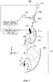
- Fig. 1 is a schematic diagram of a fundus imaging system 100.
- the x, y and z directions are defined as shown in the figure. All of these are for description, and any of them may be in the vertical direction or in the horizontal direction.
- the fundus imaging system 100 includes a light source 110, a half-silvered mirror 158, a scanning optical system 112, a detector 152, a controlling unit 154, and an image processing unit 156.
- the scanning optical system 112 has a two-dimensional scanning unit 130, a first reflection mirror 120, a plane reflection mirror 150, and a second reflection mirror 140.
- the light source 110 emits a light beam 102 to illuminate an eye 10 of a subject.
- the wavelength of the light beam 102 may be selected according to a target of the inspection, and it is, for example, the infrared region wavelength, the visible light region wavelength, and the like.
- one light source 110 is shown in the example shown in Fig. 1 , a plurality of light sources which emit light with different wavelengths may be used.
- light beams from respective light sources are placed on the same optical path by a beam combiner.
- the half-silvered mirror 158 which functions as a beam splitter transmits and reflects the light beam incident on the half-silvered mirror 158 at a predesigned ratio.
- the half-silvered mirror 158 transmits the light beam 102 from the light source 110, and it reflects the light beam 102 returned from the eye 10 and leads the light beam to the detector 152.
- the half-silvered mirror 158 may be replaced with a plurality of dichroic mirrors corresponding to respective wavelengths, and a plurality of detectors which receive light beams reflected off respective dichroic mirrors may be provided.
- Fig. 2 is a schematic diagram illustrating an arrangement of the scanning optical system 112. Note that the two-dimensional scanning unit 130 is omitted for simplicity.
- the first reflection mirror 120 has a first focus 122 and a second focus 124.
- the first reflection mirror 120 reflects a light beam 102 incident on the first reflection mirror 120 after passing through the first focus 122 so as to cause the light beam 102 to pass through the second focus 124.
- One example of the first reflection mirror 120 is an elliptical reflection mirror which has a reflection surface formed by a part of a rotary ellipsoid obtained by rotating an ellipse around a major axis including the first focus 122 and the second focus 124.
- the second reflection mirror 140 has a third focus 142 and a fourth focus 144.
- the second reflection mirror 140 reflects a light beam 102 incident on the second reflection mirror 140 after passing through the third focus 142 so as to cause the light beam 102 to pass through the fourth focus 144.
- One example of the second reflection mirror 140 is an elliptical reflection mirror which has a reflection surface formed by a part of a rotary ellipsoid obtained by rotating an ellipse around a major axis including the third focus 142 and the fourth focus 144.
- the plane reflection mirror 150 is disposed at the position of the second focus 124 of the first reflection mirror 120.
- the plane reflection mirror 150 is a plane mirror, the reflection surface thereof is disposed so as to pass through the second focus 124, the plane reflection mirror 150 may be fixed at least during scanning of the light beam 102, and the plane reflection mirror 150 may be moved for optical adjustment before or after scanning.
- the above-described positions of the plane reflection mirror 150 and the second focus 124, and furthermore, the previously described positions of the second focus 124 of the first reflection mirror 120 and the third focus 142 of the second reflection mirror 140 are ideally coincident respectively, coincidence of these positional relationships at a predetermined range is permitted.
- the range is a range that allows a scanning light beam to enter a pupil of an eye when the angle of the light beam is two-dimensionally scanned at an iris position of the subject's eye, and is a range that will not bring about obstacle to the fundus imaging.
- the plane reflection mirror 150 is disposed in a direction so that a direction of its normal C bisects an angle formed between a line segment A connecting the first focus 122 and the second focus 124 and a line segment B connecting the third focus 142 and the fourth focus 144. Thereby, the plane reflection mirror 150 reflects the light beam 102 reflected off the first reflection mirror 120 toward the second reflection mirror 140. Note that if the line segment A and the line segment B are in parallel, a direction which is orthogonal to those line segments may be handled as a normal C.
- the size of the plane reflection mirror 150 can be made the smallest by coinciding the position of the plane reflection mirror 150 with the second focus 124 (the third focus 142), as illustrated.
- the position of the plane reflection mirror 150 can also be disposed away from the second focus 124 (the third focus 142) as long as the above-described direction is maintained. That is, in the configuration, for example, shown in Fig. 2 , as long as the scanning light beam led from the first reflection mirror to the second reflection mirror is not shielded partially, the plane reflection mirror 150 can be parallelly moved to an arbitrary position. In this case, it goes without saying that the focus of the one reflection mirror is made to coincide with the imaginary focus of the other reflection mirror formed by the reflection of the plane reflection mirror 150.
- the first reflection mirror 120 and the second reflection mirror 140 are disposed in an arrangement relationship in which their reflection surfaces and rotation axes are in the same direction, that is, the rotation axes are disposed approximately on the -y side relative to the reflection surface. In other words, due to the presence of the plane reflection mirror 150, the first reflection mirror 120 and the second reflection mirror 140 do not face each other. Note that in Fig. 2 and in the other figures also, the first reflection mirror 120, the second reflection mirror 140, etc. are shown in a cross-section taken along the zy plane including the major axis.
- the rotary ellipsoid of the first reflection mirror 120 and the rotary ellipsoid of the second reflection mirror 140 have an equal eccentricity to each other. Because the equal eccentricity to each other, the consistency of angular scanning of the light beam is maintained, and distortion does not occur in the fundus image obtained by light beam scanning. This will be described later. Also, as long as the size of the first reflection mirror 120 and the size of the second reflection mirror 140 are large enough to an extent that the light in the scanning range set at the two-dimensional scanning unit 130 can be reflected, the size of the first reflection mirror 120 and the size of the second reflection mirror 140 may be equal to each other, or may be different from each other. In the example in Fig. 2 , the first reflection mirror 120 which is closer to the light source 110 is smaller than the second reflection mirror 140 which is closer to the eye 10. Thereby, the entire device can be reduced in size.
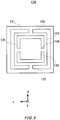
- Fig. 3 is a schematic diagram of one example of the two-dimensional scanning unit 130.
- the two-dimensional scanning unit 130 has a body 131, a frame 133 which is supported by the junction 132 so as to be rotatable around the z axis relative to the body 131, and a reflection mirror 135 which is supported by the junction 134 so as to be rotatable around the x axis relative to the frame 133, and reflects a light beam.
- the two-dimensional scanning unit 130 has a so-called gimbal structure, and is configured with, for example, MEMS, and is, for example, electrostatically driven by the controlling unit 154.
- a pupil 12 of the subject is positioned within a predefined range (a range that allows the beam light to enter when the eye is placed in the vicinity of the fourth focus) so as to coincide with the fourth focus 144 of the second reflection mirror 140.
- the controlling unit 154 causes the light beam 102 to be emitted from the light source 110, and additionally by controlling a rotation amount of the two-dimensional scanning unit 130 to rotate the reflection mirror 135 around the z axis and around the x axis, the controlling unit 154 scans with the light beam 102 from the light source 110 in the z direction and the x direction.
- the light beam 102 from the two-dimensional scanning unit 130 is reflected off the first reflection mirror 120, the plane reflection mirror 150, and the second reflection mirror 140 in this order, passes through the pupil 12, and reaches the retina.
- the light beam 102 reflected off the retina reversely traces the above-described optical path and reaches the half-silvered mirror 158.
- the light beam 102 that has been reflected off the half-silvered mirror 158 is detected at the detector 152.
- the image processing unit 156 two-dimensionally reconfigures an image of the retina, and outputs it to a monitor, etc.
- the relationship between the angular change of the light beam that the two-dimensional scanning unit 130 causes to be emitted from the first focus 122, and the angular change of the light beam which is reflected off the first reflection mirror 120 to be incident on the second focus 124 is considered.
- the two-dimensional scanning unit 130 performs scanning with the light beam by the angular change ⁇ 11 around the x axis from a certain angle
- the ratio between the angular change of the light beam which is emitted from the first focus 122, and the angular change of the light beam which is reflected off the first reflection mirror 120 and is incident on the second focus 124, corresponding to the angular change is not consistent ( ⁇ 11 / ⁇ 12 ⁇ 21 / ⁇ 22 ).
- the rotary ellipsoid of the first reflection mirror 120 and the rotary ellipsoid of the second reflection mirror 140 have equal eccentricity to each other, and additionally, the plane reflection mirror 150 is disposed in a direction so that a direction of its normal C bisects an angle formed between a line segment A and a line segment B.
- the ratio between the angular change of the light beam which is emitted from the first focus 122, and the angular change of the light beam which is incident on the fourth focus 144, corresponding to the angular changes is consistent.
- the two-dimensional image of the retina can be reconfigured without distortion in response to the rotation amount of the two-dimensional scanning unit 130. Also, because the two-dimensional scanning unit 130 is responsible for the two-dimensional scanning, and there is no mechanically movable portion during scanning at the common focus of the first reflection mirror 120 and the second reflection mirror 140, the entire device can be simplified and be reduced in size.
- Fig. 4 is a schematic diagram of another fundus imaging system 170.
- the same configurations as the fundus imaging system 100 in Fig. 1 are given the same reference numbers, and a description about them will be omitted.
- a scanning optical system 173 of the fundus imaging system 170 has a half-silvered mirror 172, instead of the plane reflection mirror 150 in Fig. 1 , at the same position and in the same direction.
- the half-silvered mirror 172 reflects the light beam 102 from the first reflection mirror and leads it to the second reflection mirror 140, while the half-silvered mirror 172 transmits a part of the light beam 102, the part reflected off the fundus oculi which returns via the second reflection mirror 140.
- an light intensity sensor 174 is disposed on the opposite side to the second reflection mirror 140 in the half-silvered mirror 172.
- the light intensity sensor 174 (for example, a photodiode) detects an intensity of the light beam 102 which has passed through the half-silvered mirror 172.
- the image of the retina can be generated based on the light intensity detected by the light intensity sensor 174.
- the position of the half-silvered mirror 172 can be disposed out of an focus position, as long as its arrangement direction is disposed in a direction so that the direction bisects an angle formed between a line segment A connecting the first focus 122 and the second focus 124 and a line segment B connecting the third focus 142 and the fourth focus 144.
- Fig. 5 is a schematic diagram of still another fundus imaging system 180.
- the same configurations as the fundus imaging system 100 in Fig. 1 are given the same reference numbers, and a description about them will be omitted.
- the first reflection mirror 120 and the second reflection mirror 140 are disposed so as to face each other.
- the second focus 124 of the first reflection mirror 120 and the third focus 142 of the second reflection mirror 140 are disposed on the same straight line.
- a rotation axis of the elliptical mirror as the first reflection mirror 120 and a rotation axis of the elliptical mirror as the second reflection mirror 140 coincide with each other.
- no optical member is disposed in the optical path to the first reflection mirror 120 and the second reflection mirror 140,.
- the two-dimensional image of the retina can be reconfigured without distortion using fewer optical members.
- All of the above-described embodiments use the shape which has reflection surfaces formed by the part of the rotary ellipsoid as the first reflection mirror 120 and the second reflection mirror 140.
- One or both of these may be replaced with other shapes.
- a combination of a part of a first paraboloid rotary body with the first focus 122 focused and a part of a second paraboloid rotary body with the second focus 124 focused may be a first reflection mirror 120.
- a second reflection mirror 140 may be a combination of parts of two paraboloid rotary bodies.
- elliptical mirrors with equal eccentricity respectively are used as the first reflection mirror 120 and the second reflection mirror 140, it is possible to configure the system by combining two parabolic mirrors and a two-dimensional scanning mirror.
- a two-dimensional scanning mirror of a light beam is disposed on a focus of a first parabolic mirror, and the pupil 12 of the subject is positioned at a focus position of a next parabolic mirror.
- inconsistency occurs in the angular scanning of the light beam with the reflection of one parabolic mirror
- inconsistency in the angular scanning of the light beam can be cancelled by combining two same parabolic mirrors.
- a clear image with little distortion aberration at the fundus image can also be obtained.
Landscapes
- Health & Medical Sciences (AREA)
- Life Sciences & Earth Sciences (AREA)
- Physics & Mathematics (AREA)
- Medical Informatics (AREA)
- Surgery (AREA)
- Engineering & Computer Science (AREA)
- Biomedical Technology (AREA)
- Heart & Thoracic Surgery (AREA)
- Biophysics (AREA)
- Molecular Biology (AREA)
- Ophthalmology & Optometry (AREA)
- Animal Behavior & Ethology (AREA)
- General Health & Medical Sciences (AREA)
- Public Health (AREA)
- Veterinary Medicine (AREA)
- General Physics & Mathematics (AREA)
- Optics & Photonics (AREA)
- Eye Examination Apparatus (AREA)
Abstract
Description
- The present invention relates to a fundus imaging system.
- Examples of a fundus scanning device that scans a retina of a subject for imaging a fundus image of the subject include a device that: vertically scans the retina with a laser beam using a polygon mirror and concurrently causes the laser beam to be incident on a first elliptical mirror; horizontally scans the retina with a light beam reflected off the first elliptical mirror using an oscillating plane mirror and concurrently causes the light beam to be incident on a second elliptical mirror; and causes a light beam reflected off the second elliptical mirror to be incident on a pupil of the subject (see, for example, Patent Document 1).
- Patent Document 1: Japanese Unexamined Patent Application Publication (Translation of
PCT Application) No. 2009-543585 - The above-described fundus scanning device, however, is disadvantageous in that the entire device is increased in size or maintenance of the device becomes difficult because an oscillating plane mirror as a mechanically driven optical system is disposed between a first elliptical mirror and a second elliptical mirror.
- According to a first aspect of the present invention, a fundus imaging system scanning a retina of a subject, including: a first reflection mirror that reflects a light beam incident on the first reflection mirror after passing through a first focus so as to cause the light beam to pass through a second focus; a two-dimensional scanning unit that is disposed at a position of the first focus of the first reflection mirror and reflects a light beam incident on the two-dimensional scanning unit so as to scan the retina with the light beam in two-dimensional directions; and a second reflection mirror that reflects a light beam incident on the second reflection mirror after passing through a third focus so as to cause the light beam to pass through a fourth focus, the second reflection mirror being disposed so that a position of the third focus coincides with a position of the second focus of the first reflection mirror, wherein a position of the pupil of the subject is disposed so as to coincide with a position of the fourth focus of the second reflection mirror.
- The summary clause does not necessarily describe all necessary features of the embodiments of the present invention. The present invention may also be a sub-combination of the features described above.
-
-
Fig. 1 is a schematic diagram of afundus imaging system 100. -
Fig. 2 is a schematic diagram illustrating an arrangement of a scanningoptical system 112. -
Fig. 3 is a schematic diagram of one example of a two-dimensional scanning unit 130. -
Fig. 4 is a schematic diagram of anotherfundus imaging system 170. -
Fig. 5 is a schematic diagram of still anotherfundus imaging system 180. - Hereinafter, the present invention is described through the embodiments of the invention. However, the following embodiments do not limit the invention according to the scope of claim. Also, all the combinations of the features described in the embodiments are not necessarily essential to means provided by aspects of the invention.
-
Fig. 1 is a schematic diagram of afundus imaging system 100. The x, y and z directions are defined as shown in the figure. All of these are for description, and any of them may be in the vertical direction or in the horizontal direction. - The
fundus imaging system 100 includes alight source 110, a half-silvered mirror 158, a scanningoptical system 112, adetector 152, a controllingunit 154, and animage processing unit 156. The scanningoptical system 112 has a two-dimensional scanning unit 130, afirst reflection mirror 120, aplane reflection mirror 150, and asecond reflection mirror 140. - The
light source 110 emits alight beam 102 to illuminate aneye 10 of a subject. The wavelength of thelight beam 102 may be selected according to a target of the inspection, and it is, for example, the infrared region wavelength, the visible light region wavelength, and the like. Although onelight source 110 is shown in the example shown inFig. 1 , a plurality of light sources which emit light with different wavelengths may be used. When the plurality of light sources are used, light beams from respective light sources are placed on the same optical path by a beam combiner. Also, it is more preferable to use a laser light as the light beam because it has good linearity. - The half-
silvered mirror 158 which functions as a beam splitter transmits and reflects the light beam incident on the half-silvered mirror 158 at a predesigned ratio. The half-silvered mirror 158 transmits thelight beam 102 from thelight source 110, and it reflects thelight beam 102 returned from theeye 10 and leads the light beam to thedetector 152. When thelight beam 102 is multicolored, the half-silvered mirror 158 may be replaced with a plurality of dichroic mirrors corresponding to respective wavelengths, and a plurality of detectors which receive light beams reflected off respective dichroic mirrors may be provided. -
Fig. 2 is a schematic diagram illustrating an arrangement of the scanningoptical system 112. Note that the two-dimensional scanning unit 130 is omitted for simplicity. - The
first reflection mirror 120 has afirst focus 122 and asecond focus 124. Thefirst reflection mirror 120 reflects alight beam 102 incident on thefirst reflection mirror 120 after passing through thefirst focus 122 so as to cause thelight beam 102 to pass through thesecond focus 124. One example of thefirst reflection mirror 120 is an elliptical reflection mirror which has a reflection surface formed by a part of a rotary ellipsoid obtained by rotating an ellipse around a major axis including thefirst focus 122 and thesecond focus 124. - The
second reflection mirror 140 has athird focus 142 and afourth focus 144. Thesecond reflection mirror 140 reflects alight beam 102 incident on thesecond reflection mirror 140 after passing through thethird focus 142 so as to cause thelight beam 102 to pass through thefourth focus 144. One example of thesecond reflection mirror 140 is an elliptical reflection mirror which has a reflection surface formed by a part of a rotary ellipsoid obtained by rotating an ellipse around a major axis including thethird focus 142 and thefourth focus 144. - About the position of the
third focus 142 of thesecond reflection mirror 140 and the position of thesecond focus 124 of thefirst reflection mirror 120, there may be cases where the respective positions are completely coincident as shown inFig. 2 , or, where they are the same in design, but are inevitably misaligned due to assembling error, etc.. - The
plane reflection mirror 150 is disposed at the position of thesecond focus 124 of thefirst reflection mirror 120. In an example shown inFig. 2 , theplane reflection mirror 150 is a plane mirror, the reflection surface thereof is disposed so as to pass through thesecond focus 124, theplane reflection mirror 150 may be fixed at least during scanning of thelight beam 102, and theplane reflection mirror 150 may be moved for optical adjustment before or after scanning. Although it is preferable that the above-described positions of theplane reflection mirror 150 and thesecond focus 124, and furthermore, the previously described positions of thesecond focus 124 of thefirst reflection mirror 120 and thethird focus 142 of thesecond reflection mirror 140 are ideally coincident respectively, coincidence of these positional relationships at a predetermined range is permitted. The range is a range that allows a scanning light beam to enter a pupil of an eye when the angle of the light beam is two-dimensionally scanned at an iris position of the subject's eye, and is a range that will not bring about obstacle to the fundus imaging. - The
plane reflection mirror 150 is disposed in a direction so that a direction of its normal C bisects an angle formed between a line segment A connecting thefirst focus 122 and thesecond focus 124 and a line segment B connecting thethird focus 142 and thefourth focus 144. Thereby, theplane reflection mirror 150 reflects thelight beam 102 reflected off thefirst reflection mirror 120 toward thesecond reflection mirror 140. Note that if the line segment A and the line segment B are in parallel, a direction which is orthogonal to those line segments may be handled as a normal C. - Note that the size of the
plane reflection mirror 150 can be made the smallest by coinciding the position of theplane reflection mirror 150 with the second focus 124 (the third focus 142), as illustrated. The position of theplane reflection mirror 150, however, can also be disposed away from the second focus 124 (the third focus 142) as long as the above-described direction is maintained. That is, in the configuration, for example, shown inFig. 2 , as long as the scanning light beam led from the first reflection mirror to the second reflection mirror is not shielded partially, theplane reflection mirror 150 can be parallelly moved to an arbitrary position. In this case, it goes without saying that the focus of the one reflection mirror is made to coincide with the imaginary focus of the other reflection mirror formed by the reflection of theplane reflection mirror 150. - The
first reflection mirror 120 and thesecond reflection mirror 140 are disposed in an arrangement relationship in which their reflection surfaces and rotation axes are in the same direction, that is, the rotation axes are disposed approximately on the -y side relative to the reflection surface. In other words, due to the presence of theplane reflection mirror 150, thefirst reflection mirror 120 and thesecond reflection mirror 140 do not face each other. Note that inFig. 2 and in the other figures also, thefirst reflection mirror 120, thesecond reflection mirror 140, etc. are shown in a cross-section taken along the zy plane including the major axis. - The rotary ellipsoid of the
first reflection mirror 120 and the rotary ellipsoid of thesecond reflection mirror 140 have an equal eccentricity to each other. Because the equal eccentricity to each other, the consistency of angular scanning of the light beam is maintained, and distortion does not occur in the fundus image obtained by light beam scanning. This will be described later. Also, as long as the size of thefirst reflection mirror 120 and the size of thesecond reflection mirror 140 are large enough to an extent that the light in the scanning range set at the two-dimensional scanning unit 130 can be reflected, the size of thefirst reflection mirror 120 and the size of thesecond reflection mirror 140 may be equal to each other, or may be different from each other. In the example inFig. 2 , thefirst reflection mirror 120 which is closer to thelight source 110 is smaller than thesecond reflection mirror 140 which is closer to theeye 10. Thereby, the entire device can be reduced in size. -
Fig. 3 is a schematic diagram of one example of the two-dimensional scanning unit 130. The two-dimensional scanning unit 130 has abody 131, aframe 133 which is supported by thejunction 132 so as to be rotatable around the z axis relative to thebody 131, and areflection mirror 135 which is supported by thejunction 134 so as to be rotatable around the x axis relative to theframe 133, and reflects a light beam. The two-dimensional scanning unit 130 has a so-called gimbal structure, and is configured with, for example, MEMS, and is, for example, electrostatically driven by the controllingunit 154. - In the above-described configuration, a
pupil 12 of the subject is positioned within a predefined range (a range that allows the beam light to enter when the eye is placed in the vicinity of the fourth focus) so as to coincide with thefourth focus 144 of thesecond reflection mirror 140. The controllingunit 154 causes thelight beam 102 to be emitted from thelight source 110, and additionally by controlling a rotation amount of the two-dimensional scanning unit 130 to rotate thereflection mirror 135 around the z axis and around the x axis, the controllingunit 154 scans with thelight beam 102 from thelight source 110 in the z direction and the x direction. - The
light beam 102 from the two-dimensional scanning unit 130 is reflected off thefirst reflection mirror 120, theplane reflection mirror 150, and thesecond reflection mirror 140 in this order, passes through thepupil 12, and reaches the retina. Thelight beam 102 reflected off the retina reversely traces the above-described optical path and reaches the half-silveredmirror 158. Thelight beam 102 that has been reflected off the half-silveredmirror 158 is detected at thedetector 152. Based on the rotation amount of the two-dimensional scanning unit 130 controlled by the controllingunit 154, and the light amount detected by thedetector 152, theimage processing unit 156 two-dimensionally reconfigures an image of the retina, and outputs it to a monitor, etc. - Here, the relationship between the angular change of the light beam that the two-
dimensional scanning unit 130 causes to be emitted from thefirst focus 122, and the angular change of the light beam which is reflected off thefirst reflection mirror 120 to be incident on thesecond focus 124 is considered. For example, the case where the two-dimensional scanning unit 130 performs scanning with the light beam by the angular change θ11 around the x axis from a certain angle, and the case where the two-dimensional scanning unit 130 scans with the light beam by the same angular change θ12 (that is, θ11=θ2) further around the x axis, as shown inFig. 1 , are considered. - Because in the above-described scanning, changes in curvatures of reflection portions of the
first reflection mirror 120 differ respectively, respective angular changes θ21, θ22 at which the reflected light beam heads to thesecond focus 124 relative to the same angular changes θ11, θ12 differ in general (that is, θ21≠θ22). Although the angles can be geometrically calculated respectively, such as θ21<θ22 in the example inFig. 1 . - In other words, the ratio between the angular change of the light beam which is emitted from the
first focus 122, and the angular change of the light beam which is reflected off thefirst reflection mirror 120 and is incident on thesecond focus 124, corresponding to the angular change is not consistent (θ11/θ12≠θ21/θ22). - An angle of incidence and an angle of reflection with respect to the plane mirror are equal. Thus, assuming that angular changes of reflection at the
plane reflection mirror 150 relative to the angular changes θ21, θ22 are respectively θ31, θ32, θ21=θ31, θ22=θ32 are satisfied. - In the embodiment, the rotary ellipsoid of the
first reflection mirror 120 and the rotary ellipsoid of thesecond reflection mirror 140 have equal eccentricity to each other, and additionally, theplane reflection mirror 150 is disposed in a direction so that a direction of its normal C bisects an angle formed between a line segment A and a line segment B. From the above, θ11/θ12=θ41/θ42 is satisfied. In other words, the ratio between the angular change of the light beam which is emitted from thefirst focus 122, and the angular change of the light beam which is incident on thefourth focus 144, corresponding to the angular changes is consistent. And, obviously, θ11=θ41, θ12=θ42 are satisfied. - In accordance with the above-described configuration, the two-dimensional image of the retina can be reconfigured without distortion in response to the rotation amount of the two-
dimensional scanning unit 130. Also, because the two-dimensional scanning unit 130 is responsible for the two-dimensional scanning, and there is no mechanically movable portion during scanning at the common focus of thefirst reflection mirror 120 and thesecond reflection mirror 140, the entire device can be simplified and be reduced in size. -
Fig. 4 is a schematic diagram of anotherfundus imaging system 170. In thefundus imaging system 170, the same configurations as thefundus imaging system 100 inFig. 1 are given the same reference numbers, and a description about them will be omitted. - A scanning
optical system 173 of thefundus imaging system 170 has a half-silveredmirror 172, instead of theplane reflection mirror 150 inFig. 1 , at the same position and in the same direction. The half-silveredmirror 172 reflects thelight beam 102 from the first reflection mirror and leads it to thesecond reflection mirror 140, while the half-silveredmirror 172 transmits a part of thelight beam 102, the part reflected off the fundus oculi which returns via thesecond reflection mirror 140. - Furthermore, instead of the
detector 152 of thefundus imaging system 100, in thefundus imaging system 170, anlight intensity sensor 174 is disposed on the opposite side to thesecond reflection mirror 140 in the half-silveredmirror 172. The light intensity sensor 174 (for example, a photodiode) detects an intensity of thelight beam 102 which has passed through the half-silveredmirror 172. - By the above-described configuration, corresponding to the two-dimensionally scanning of the
light beam 102 by the two-dimensional scanning unit 130, the image of the retina can be generated based on the light intensity detected by thelight intensity sensor 174. Note that in a similar way to the previously describedplane reflection mirror 150 shown inFig. 1 and theFig. 2 , the position of the half-silveredmirror 172 can be disposed out of an focus position, as long as its arrangement direction is disposed in a direction so that the direction bisects an angle formed between a line segment A connecting thefirst focus 122 and thesecond focus 124 and a line segment B connecting thethird focus 142 and thefourth focus 144. -
Fig. 5 is a schematic diagram of still anotherfundus imaging system 180. In thefundus imaging system 180, the same configurations as thefundus imaging system 100 inFig. 1 are given the same reference numbers, and a description about them will be omitted. - In a scanning
optical system 184 of thefundus imaging system 180, thefirst reflection mirror 120 and thesecond reflection mirror 140 are disposed so as to face each other. Thesecond focus 124 of thefirst reflection mirror 120 and thethird focus 142 of thesecond reflection mirror 140 are disposed on the same straight line. In other words, a rotation axis of the elliptical mirror as thefirst reflection mirror 120 and a rotation axis of the elliptical mirror as thesecond reflection mirror 140 coincide with each other. In this configuration, different from thefundus imaging system 100, no optical member is disposed in the optical path to thefirst reflection mirror 120 and thesecond reflection mirror 140,. - By the above-described configuration, the two-dimensional image of the retina can be reconfigured without distortion using fewer optical members.
- All of the above-described embodiments use the shape which has reflection surfaces formed by the part of the rotary ellipsoid as the
first reflection mirror 120 and thesecond reflection mirror 140. One or both of these may be replaced with other shapes. For example, a combination of a part of a first paraboloid rotary body with thefirst focus 122 focused and a part of a second paraboloid rotary body with thesecond focus 124 focused may be afirst reflection mirror 120. In a similar way, asecond reflection mirror 140 may be a combination of parts of two paraboloid rotary bodies. - Note that in the configuration of the above-described implementation, elliptical mirrors with equal eccentricity respectively are used as the
first reflection mirror 120 and thesecond reflection mirror 140, it is possible to configure the system by combining two parabolic mirrors and a two-dimensional scanning mirror. A two-dimensional scanning mirror of a light beam is disposed on a focus of a first parabolic mirror, and thepupil 12 of the subject is positioned at a focus position of a next parabolic mirror. Although in a similar way as one elliptical mirror, inconsistency occurs in the angular scanning of the light beam with the reflection of one parabolic mirror, inconsistency in the angular scanning of the light beam can be cancelled by combining two same parabolic mirrors. By this configuration, a clear image with little distortion aberration at the fundus image can also be obtained. - While the embodiments of the present invention have been described, the technical scope of the invention is not limited to the above described embodiments. It is apparent to persons skilled in the art that various alterations and improvements can be added to the above-described embodiments. It is also apparent from the scope of the claims that the embodiments added with such alterations or improvements can be included in the technical scope of the invention.
- The operations, procedures, steps, and stages of each process performed by an apparatus, system, program, and method shown in the claims, embodiments, or diagrams can be performed in any order as long as the order is not indicated by "prior to," "before," or the like and as long as the output from a previous process is not used in a later process. Even if the process flow is described using phrases such as "first" or "next" in the claims, embodiments, or diagrams, it does not necessarily mean that the process must be performed in this order.
- 10: eye, 12: pupil, 100: fundus imaging system, 102: light beam, 110: light source, 112: scanning optical system, 120: first reflection mirror, 122: first focus, 124: second focus, 130: two-dimensional scanning unit, 131: body, 132: junction, 133: frame, 134: junction, 135: reflection mirror, 140: second reflection mirror, 142: third focus, 144: fourth focus, 150: plane reflection mirror, 152: detector, 154: controlling unit, 156: image processing unit, 158: half-silvered mirror, 170: fundus imaging system, 172: half-silvered mirror, 173: scanning optical system, 174: light intensity sensor, 180: fundus imaging system, and 184: scanning optical system
Claims (9)
- A fundus imaging system that scans a retina of a subject, the system comprising:a first reflection mirror that reflects a light beam incident on the first reflection mirror after passing through a first focus of the first reflection mirror so as to cause the light beam to pass through a second focus;a two-dimensional scanning unit that is disposed at a position of the first focus of the first reflection mirror and reflects a light beam incident on the two-dimensional scanning unit so as to scan the retina with the light beam in two-dimensional directions; anda second reflection mirror that reflects a light beam incident on the second reflection mirror after passing through a third focus so as to cause the light beam to pass through a fourth focus, the second reflection mirror being disposed so that a position of the third focus coincides with a position of the second focus of the first reflection mirror, whereina position of the pupil of the subject is disposed so as to coincide with a position of the fourth focus of the second reflection mirror.
- The fundus imaging system according to Claim 1, whereinthe two-dimensional scanning unit has:a body;a frame supported by the body so as to be rotatable in a first direction relative to the body; anda reflection mirror supported by the frame so as to be rotatable in a second direction orthogonal to the first direction relative to the body, the reflection mirror reflecting a light beam.
- The fundus imaging system according to Claim 1 or 2, further comprising a plane reflection mirror that reflects a light beam reflected off the first reflection mirror toward the second reflection mirror.
- The fundus imaging system according to Claim 3, whereinthe plane reflection mirror transmits a part of a light beam returned from the second reflection mirror,further comprising a detecting unit that detects the light beam that has been transmitted through the plane reflection mirror.
- The fundus imaging system according to Claim 3 or 4, whereinthe plane reflection mirror having a normal in a direction that bisects an angle formed between a line segment connecting the first focus and the second focus and a line segment connecting the third focus and the fourth focus.
- The fundus imaging system according to Claim 1, whereinthe first reflection mirror and the second reflection mirror are disposed so as to face each other.
- The fundus imaging system according to any one of Claims 1 to 6, whereinthe first reflection mirror and the second reflection mirror have reflection surfaces formed by parts of rotary ellipsoids.
- The fundus imaging system according to Claim 7, whereinthe first reflection mirror and the second reflection mirror have reflection surfaces formed by parts of rotary ellipsoids, the rotary ellipsoids having an equal eccentricity to each other.
- The fundus imaging system according to any one of Claims 1 to 8, whereinthe first reflection mirror is smaller than the second reflection mirror.
Applications Claiming Priority (1)
| Application Number | Priority Date | Filing Date | Title |
|---|---|---|---|
| PCT/JP2014/084630 WO2016103489A1 (en) | 2014-12-26 | 2014-12-26 | Fundus image forming device |
Publications (3)
| Publication Number | Publication Date |
|---|---|
| EP3238609A1 true EP3238609A1 (en) | 2017-11-01 |
| EP3238609A4 EP3238609A4 (en) | 2018-08-08 |
| EP3238609B1 EP3238609B1 (en) | 2021-10-20 |
Family
ID=56149572
Family Applications (1)
| Application Number | Title | Priority Date | Filing Date |
|---|---|---|---|
| EP14909092.0A Active EP3238609B1 (en) | 2014-12-26 | 2014-12-26 | Fundus image forming device |
Country Status (5)
| Country | Link |
|---|---|
| US (1) | US10398311B2 (en) |
| EP (1) | EP3238609B1 (en) |
| JP (1) | JP6380556B2 (en) |
| CN (1) | CN107106009B (en) |
| WO (1) | WO2016103489A1 (en) |
Families Citing this family (10)
| Publication number | Priority date | Publication date | Assignee | Title |
|---|---|---|---|---|
| CN108567409B (en) * | 2017-03-13 | 2023-11-03 | 温州高视雷蒙光电科技有限公司 | Off-axis reflector retina imaging system |
| EP3690517B1 (en) * | 2017-09-29 | 2023-11-01 | QD Laser, Inc. | Image projection device |
| JP7050292B2 (en) * | 2018-03-28 | 2022-04-08 | 株式会社Qdレーザ | Image projection device |
| JP7231404B2 (en) * | 2018-12-26 | 2023-03-01 | 株式会社トプコン | Ophthalmic device and its control method |
| US12307639B2 (en) | 2019-08-30 | 2025-05-20 | Nikon Corporation | Image processing method, image processing device, and program |
| CN113842108A (en) * | 2021-09-15 | 2021-12-28 | 北京大学 | Imaging system for fundus retina |
| WO2025204899A1 (en) * | 2024-03-28 | 2025-10-02 | 株式会社トプコン | Fundus observation device |
| CN118749900B (en) * | 2024-07-18 | 2025-11-04 | 华中科技大学 | Rotating parabolic fundus imaging system and imaging method |
| JP2026038457A (en) * | 2024-08-23 | 2026-03-06 | 株式会社トプコン | Ophthalmic device and method for operating the device |
| CN120036723A (en) * | 2025-04-22 | 2025-05-27 | 执鼎医疗科技有限公司 | Ultra-wide-angle fundus imaging system and imaging equipment |
Family Cites Families (12)
| Publication number | Priority date | Publication date | Assignee | Title |
|---|---|---|---|---|
| GB9323065D0 (en) | 1993-11-09 | 1994-01-05 | Besca Ltd | A wide field retinal scanning ophthalmoscope |
| JP4680373B2 (en) * | 2000-11-16 | 2011-05-11 | オリンパス株式会社 | Galvano mirror |
| GB2440163A (en) | 2006-07-15 | 2008-01-23 | Optos Plc | Scanning ophthalmoscope with reduced shear distortion |
| GB0622325D0 (en) | 2006-11-09 | 2006-12-20 | Optos Plc | Improvements in or relating to retinal scanning |
| GB0907557D0 (en) | 2009-05-01 | 2009-06-10 | Optos Plc | Improvements in or relating to scanning ophthalmoscopes |
| GB0913911D0 (en) | 2009-08-10 | 2009-09-16 | Optos Plc | Improvements in or relating to laser scanning systems |
| GB201007046D0 (en) | 2010-04-28 | 2010-06-09 | Optos Plc | Improvements in or relating to scanning ophthalmoscopes |
| US8284478B2 (en) | 2010-06-30 | 2012-10-09 | Femtolasers Produktions Gmbh | Device for increasing the spectral bandwidth of optical pulses as well as an arrangement and a method for reducing the duration of optical pulses with the use of such a device |
| GB201011095D0 (en) * | 2010-07-01 | 2010-08-18 | Optos Plc | Improvements in or relating to ophthalmology |
| GB201100555D0 (en) * | 2011-01-13 | 2011-03-02 | Optos Plc | Improvements in or relating to Ophthalmology |
| GB201307936D0 (en) | 2013-05-02 | 2013-06-12 | Optos Plc | Improvements in and relating to ophthalmoscopes |
| JP2016067551A (en) * | 2014-09-29 | 2016-05-09 | キヤノン株式会社 | Ophthalmic equipment |
-
2014
- 2014-12-26 JP JP2016565831A patent/JP6380556B2/en active Active
- 2014-12-26 WO PCT/JP2014/084630 patent/WO2016103489A1/en not_active Ceased
- 2014-12-26 CN CN201480084344.3A patent/CN107106009B/en active Active
- 2014-12-26 EP EP14909092.0A patent/EP3238609B1/en active Active
-
2017
- 2017-06-22 US US15/630,324 patent/US10398311B2/en active Active
Also Published As
| Publication number | Publication date |
|---|---|
| CN107106009B (en) | 2019-09-13 |
| US20170347881A1 (en) | 2017-12-07 |
| US10398311B2 (en) | 2019-09-03 |
| WO2016103489A1 (en) | 2016-06-30 |
| JP6380556B2 (en) | 2018-08-29 |
| CN107106009A (en) | 2017-08-29 |
| EP3238609B1 (en) | 2021-10-20 |
| JPWO2016103489A1 (en) | 2017-09-07 |
| EP3238609A4 (en) | 2018-08-08 |
Similar Documents
| Publication | Publication Date | Title |
|---|---|---|
| US10398311B2 (en) | Fundus image forming device | |
| EP3195793B1 (en) | Improvements in or relating to ophthalmology | |
| KR101629911B1 (en) | Imaging technique for optical coherence tomography | |
| US20120133888A1 (en) | scanning ophthalmoscopes | |
| EP3150109B1 (en) | Fundus imaging device | |
| US9649025B2 (en) | Scanning optical system with multiple optical sources | |
| US10362938B2 (en) | Fundus image forming device | |
| JP6776777B2 (en) | Fundus photography device | |
| ES2787207T3 (en) | Ophthalmoscopes | |
| JP2021170033A (en) | Scanner | |
| JP2020516866A (en) | Optical scanning system | |
| JP2017064219A (en) | Fundus photographing device | |
| CN110662980A (en) | Method and apparatus for scanning spatial angles | |
| JP6525099B2 (en) | Fundus image forming device | |
| CN118679414A (en) | Eye scanning device | |
| JP2019058745A (en) | Fundus image formation apparatus |
Legal Events
| Date | Code | Title | Description |
|---|---|---|---|
| STAA | Information on the status of an ep patent application or granted ep patent |
Free format text: STATUS: THE INTERNATIONAL PUBLICATION HAS BEEN MADE |
|
| PUAI | Public reference made under article 153(3) epc to a published international application that has entered the european phase |
Free format text: ORIGINAL CODE: 0009012 |
|
| STAA | Information on the status of an ep patent application or granted ep patent |
Free format text: STATUS: REQUEST FOR EXAMINATION WAS MADE |
|
| 17P | Request for examination filed |
Effective date: 20170724 |
|
| AK | Designated contracting states |
Kind code of ref document: A1 Designated state(s): AL AT BE BG CH CY CZ DE DK EE ES FI FR GB GR HR HU IE IS IT LI LT LU LV MC MK MT NL NO PL PT RO RS SE SI SK SM TR |
|
| AX | Request for extension of the european patent |
Extension state: BA ME |
|
| DAX | Request for extension of the european patent (deleted) | ||
| A4 | Supplementary search report drawn up and despatched |
Effective date: 20180709 |
|
| RIC1 | Information provided on ipc code assigned before grant |
Ipc: A61B 3/10 20060101ALI20180703BHEP Ipc: A61B 3/12 20060101AFI20180703BHEP |
|
| GRAP | Despatch of communication of intention to grant a patent |
Free format text: ORIGINAL CODE: EPIDOSNIGR1 |
|
| STAA | Information on the status of an ep patent application or granted ep patent |
Free format text: STATUS: GRANT OF PATENT IS INTENDED |
|
| INTG | Intention to grant announced |
Effective date: 20210707 |
|
| GRAS | Grant fee paid |
Free format text: ORIGINAL CODE: EPIDOSNIGR3 |
|
| GRAA | (expected) grant |
Free format text: ORIGINAL CODE: 0009210 |
|
| STAA | Information on the status of an ep patent application or granted ep patent |
Free format text: STATUS: THE PATENT HAS BEEN GRANTED |
|
| AK | Designated contracting states |
Kind code of ref document: B1 Designated state(s): AL AT BE BG CH CY CZ DE DK EE ES FI FR GB GR HR HU IE IS IT LI LT LU LV MC MK MT NL NO PL PT RO RS SE SI SK SM TR |
|
| REG | Reference to a national code |
Ref country code: GB Ref legal event code: FG4D |
|
| REG | Reference to a national code |
Ref country code: CH Ref legal event code: EP |
|
| REG | Reference to a national code |
Ref country code: IE Ref legal event code: FG4D |
|
| REG | Reference to a national code |
Ref country code: DE Ref legal event code: R096 Ref document number: 602014080829 Country of ref document: DE |
|
| REG | Reference to a national code |
Ref country code: AT Ref legal event code: REF Ref document number: 1439229 Country of ref document: AT Kind code of ref document: T Effective date: 20211115 |
|
| REG | Reference to a national code |
Ref country code: LT Ref legal event code: MG9D |
|
| REG | Reference to a national code |
Ref country code: NL Ref legal event code: MP Effective date: 20211020 |
|
| REG | Reference to a national code |
Ref country code: AT Ref legal event code: MK05 Ref document number: 1439229 Country of ref document: AT Kind code of ref document: T Effective date: 20211020 |
|
| PG25 | Lapsed in a contracting state [announced via postgrant information from national office to epo] |
Ref country code: RS Free format text: LAPSE BECAUSE OF FAILURE TO SUBMIT A TRANSLATION OF THE DESCRIPTION OR TO PAY THE FEE WITHIN THE PRESCRIBED TIME-LIMIT Effective date: 20211020 Ref country code: LT Free format text: LAPSE BECAUSE OF FAILURE TO SUBMIT A TRANSLATION OF THE DESCRIPTION OR TO PAY THE FEE WITHIN THE PRESCRIBED TIME-LIMIT Effective date: 20211020 Ref country code: FI Free format text: LAPSE BECAUSE OF FAILURE TO SUBMIT A TRANSLATION OF THE DESCRIPTION OR TO PAY THE FEE WITHIN THE PRESCRIBED TIME-LIMIT Effective date: 20211020 Ref country code: BG Free format text: LAPSE BECAUSE OF FAILURE TO SUBMIT A TRANSLATION OF THE DESCRIPTION OR TO PAY THE FEE WITHIN THE PRESCRIBED TIME-LIMIT Effective date: 20220120 Ref country code: AT Free format text: LAPSE BECAUSE OF FAILURE TO SUBMIT A TRANSLATION OF THE DESCRIPTION OR TO PAY THE FEE WITHIN THE PRESCRIBED TIME-LIMIT Effective date: 20211020 |
|
| PG25 | Lapsed in a contracting state [announced via postgrant information from national office to epo] |
Ref country code: IS Free format text: LAPSE BECAUSE OF FAILURE TO SUBMIT A TRANSLATION OF THE DESCRIPTION OR TO PAY THE FEE WITHIN THE PRESCRIBED TIME-LIMIT Effective date: 20220220 Ref country code: SE Free format text: LAPSE BECAUSE OF FAILURE TO SUBMIT A TRANSLATION OF THE DESCRIPTION OR TO PAY THE FEE WITHIN THE PRESCRIBED TIME-LIMIT Effective date: 20211020 Ref country code: PT Free format text: LAPSE BECAUSE OF FAILURE TO SUBMIT A TRANSLATION OF THE DESCRIPTION OR TO PAY THE FEE WITHIN THE PRESCRIBED TIME-LIMIT Effective date: 20220221 Ref country code: PL Free format text: LAPSE BECAUSE OF FAILURE TO SUBMIT A TRANSLATION OF THE DESCRIPTION OR TO PAY THE FEE WITHIN THE PRESCRIBED TIME-LIMIT Effective date: 20211020 Ref country code: NO Free format text: LAPSE BECAUSE OF FAILURE TO SUBMIT A TRANSLATION OF THE DESCRIPTION OR TO PAY THE FEE WITHIN THE PRESCRIBED TIME-LIMIT Effective date: 20220120 Ref country code: NL Free format text: LAPSE BECAUSE OF FAILURE TO SUBMIT A TRANSLATION OF THE DESCRIPTION OR TO PAY THE FEE WITHIN THE PRESCRIBED TIME-LIMIT Effective date: 20211020 Ref country code: LV Free format text: LAPSE BECAUSE OF FAILURE TO SUBMIT A TRANSLATION OF THE DESCRIPTION OR TO PAY THE FEE WITHIN THE PRESCRIBED TIME-LIMIT Effective date: 20211020 Ref country code: HR Free format text: LAPSE BECAUSE OF FAILURE TO SUBMIT A TRANSLATION OF THE DESCRIPTION OR TO PAY THE FEE WITHIN THE PRESCRIBED TIME-LIMIT Effective date: 20211020 Ref country code: GR Free format text: LAPSE BECAUSE OF FAILURE TO SUBMIT A TRANSLATION OF THE DESCRIPTION OR TO PAY THE FEE WITHIN THE PRESCRIBED TIME-LIMIT Effective date: 20220121 Ref country code: ES Free format text: LAPSE BECAUSE OF FAILURE TO SUBMIT A TRANSLATION OF THE DESCRIPTION OR TO PAY THE FEE WITHIN THE PRESCRIBED TIME-LIMIT Effective date: 20211020 |
|
| REG | Reference to a national code |
Ref country code: DE Ref legal event code: R097 Ref document number: 602014080829 Country of ref document: DE |
|
| PG25 | Lapsed in a contracting state [announced via postgrant information from national office to epo] |
Ref country code: SM Free format text: LAPSE BECAUSE OF FAILURE TO SUBMIT A TRANSLATION OF THE DESCRIPTION OR TO PAY THE FEE WITHIN THE PRESCRIBED TIME-LIMIT Effective date: 20211020 Ref country code: SK Free format text: LAPSE BECAUSE OF FAILURE TO SUBMIT A TRANSLATION OF THE DESCRIPTION OR TO PAY THE FEE WITHIN THE PRESCRIBED TIME-LIMIT Effective date: 20211020 Ref country code: RO Free format text: LAPSE BECAUSE OF FAILURE TO SUBMIT A TRANSLATION OF THE DESCRIPTION OR TO PAY THE FEE WITHIN THE PRESCRIBED TIME-LIMIT Effective date: 20211020 Ref country code: MC Free format text: LAPSE BECAUSE OF FAILURE TO SUBMIT A TRANSLATION OF THE DESCRIPTION OR TO PAY THE FEE WITHIN THE PRESCRIBED TIME-LIMIT Effective date: 20211020 Ref country code: EE Free format text: LAPSE BECAUSE OF FAILURE TO SUBMIT A TRANSLATION OF THE DESCRIPTION OR TO PAY THE FEE WITHIN THE PRESCRIBED TIME-LIMIT Effective date: 20211020 Ref country code: DK Free format text: LAPSE BECAUSE OF FAILURE TO SUBMIT A TRANSLATION OF THE DESCRIPTION OR TO PAY THE FEE WITHIN THE PRESCRIBED TIME-LIMIT Effective date: 20211020 Ref country code: CZ Free format text: LAPSE BECAUSE OF FAILURE TO SUBMIT A TRANSLATION OF THE DESCRIPTION OR TO PAY THE FEE WITHIN THE PRESCRIBED TIME-LIMIT Effective date: 20211020 |
|
| REG | Reference to a national code |
Ref country code: CH Ref legal event code: PL |
|
| PLBE | No opposition filed within time limit |
Free format text: ORIGINAL CODE: 0009261 |
|
| STAA | Information on the status of an ep patent application or granted ep patent |
Free format text: STATUS: NO OPPOSITION FILED WITHIN TIME LIMIT |
|
| REG | Reference to a national code |
Ref country code: BE Ref legal event code: MM Effective date: 20211231 |
|
| 26N | No opposition filed |
Effective date: 20220721 |
|
| PG25 | Lapsed in a contracting state [announced via postgrant information from national office to epo] |
Ref country code: LU Free format text: LAPSE BECAUSE OF NON-PAYMENT OF DUE FEES Effective date: 20211226 Ref country code: IE Free format text: LAPSE BECAUSE OF NON-PAYMENT OF DUE FEES Effective date: 20211226 Ref country code: AL Free format text: LAPSE BECAUSE OF FAILURE TO SUBMIT A TRANSLATION OF THE DESCRIPTION OR TO PAY THE FEE WITHIN THE PRESCRIBED TIME-LIMIT Effective date: 20211020 |
|
| PG25 | Lapsed in a contracting state [announced via postgrant information from national office to epo] |
Ref country code: SI Free format text: LAPSE BECAUSE OF FAILURE TO SUBMIT A TRANSLATION OF THE DESCRIPTION OR TO PAY THE FEE WITHIN THE PRESCRIBED TIME-LIMIT Effective date: 20211020 Ref country code: FR Free format text: LAPSE BECAUSE OF NON-PAYMENT OF DUE FEES Effective date: 20211231 Ref country code: BE Free format text: LAPSE BECAUSE OF NON-PAYMENT OF DUE FEES Effective date: 20211231 |
|
| PG25 | Lapsed in a contracting state [announced via postgrant information from national office to epo] |
Ref country code: LI Free format text: LAPSE BECAUSE OF NON-PAYMENT OF DUE FEES Effective date: 20211231 Ref country code: CH Free format text: LAPSE BECAUSE OF NON-PAYMENT OF DUE FEES Effective date: 20211231 |
|
| PG25 | Lapsed in a contracting state [announced via postgrant information from national office to epo] |
Ref country code: IT Free format text: LAPSE BECAUSE OF FAILURE TO SUBMIT A TRANSLATION OF THE DESCRIPTION OR TO PAY THE FEE WITHIN THE PRESCRIBED TIME-LIMIT Effective date: 20211020 Ref country code: HU Free format text: LAPSE BECAUSE OF FAILURE TO SUBMIT A TRANSLATION OF THE DESCRIPTION OR TO PAY THE FEE WITHIN THE PRESCRIBED TIME-LIMIT; INVALID AB INITIO Effective date: 20141226 |
|
| P01 | Opt-out of the competence of the unified patent court (upc) registered |
Effective date: 20230517 |
|
| PG25 | Lapsed in a contracting state [announced via postgrant information from national office to epo] |
Ref country code: CY Free format text: LAPSE BECAUSE OF FAILURE TO SUBMIT A TRANSLATION OF THE DESCRIPTION OR TO PAY THE FEE WITHIN THE PRESCRIBED TIME-LIMIT Effective date: 20211020 |
|
| PG25 | Lapsed in a contracting state [announced via postgrant information from national office to epo] |
Ref country code: MK Free format text: LAPSE BECAUSE OF FAILURE TO SUBMIT A TRANSLATION OF THE DESCRIPTION OR TO PAY THE FEE WITHIN THE PRESCRIBED TIME-LIMIT Effective date: 20211020 |
|
| PG25 | Lapsed in a contracting state [announced via postgrant information from national office to epo] |
Ref country code: TR Free format text: LAPSE BECAUSE OF FAILURE TO SUBMIT A TRANSLATION OF THE DESCRIPTION OR TO PAY THE FEE WITHIN THE PRESCRIBED TIME-LIMIT Effective date: 20211020 |
|
| PG25 | Lapsed in a contracting state [announced via postgrant information from national office to epo] |
Ref country code: MT Free format text: LAPSE BECAUSE OF FAILURE TO SUBMIT A TRANSLATION OF THE DESCRIPTION OR TO PAY THE FEE WITHIN THE PRESCRIBED TIME-LIMIT Effective date: 20211020 |
|
| PGFP | Annual fee paid to national office [announced via postgrant information from national office to epo] |
Ref country code: DE Payment date: 20251028 Year of fee payment: 12 |
|
| PGFP | Annual fee paid to national office [announced via postgrant information from national office to epo] |
Ref country code: GB Payment date: 20251114 Year of fee payment: 12 |