EP3237712B1 - Hinge for pieces of furniture with deactivatable deceleration device - Google Patents
Hinge for pieces of furniture with deactivatable deceleration device Download PDFInfo
- Publication number
- EP3237712B1 EP3237712B1 EP15808240.4A EP15808240A EP3237712B1 EP 3237712 B1 EP3237712 B1 EP 3237712B1 EP 15808240 A EP15808240 A EP 15808240A EP 3237712 B1 EP3237712 B1 EP 3237712B1
- Authority
- EP
- European Patent Office
- Prior art keywords
- deceleration
- deactivation
- rocker
- hinge according
- hinge
- Prior art date
- Legal status (The legal status is an assumption and is not a legal conclusion. Google has not performed a legal analysis and makes no representation as to the accuracy of the status listed.)
- Active
Links
- 230000009849 deactivation Effects 0.000 claims description 39
- 230000004913 activation Effects 0.000 claims description 9
- 230000010355 oscillation Effects 0.000 claims description 2
- 230000003213 activating effect Effects 0.000 claims 1
- 230000008878 coupling Effects 0.000 description 2
- 238000010168 coupling process Methods 0.000 description 2
- 238000005859 coupling reaction Methods 0.000 description 2
- 230000000670 limiting effect Effects 0.000 description 2
- 230000000694 effects Effects 0.000 description 1
- 239000004519 grease Substances 0.000 description 1
- 230000007246 mechanism Effects 0.000 description 1
- 230000004048 modification Effects 0.000 description 1
- 238000012986 modification Methods 0.000 description 1
Images


Classifications
-
- E—FIXED CONSTRUCTIONS
- E05—LOCKS; KEYS; WINDOW OR DOOR FITTINGS; SAFES
- E05F—DEVICES FOR MOVING WINGS INTO OPEN OR CLOSED POSITION; CHECKS FOR WINGS; WING FITTINGS NOT OTHERWISE PROVIDED FOR, CONCERNED WITH THE FUNCTIONING OF THE WING
- E05F5/00—Braking devices, e.g. checks; Stops; Buffers
- E05F5/006—Braking devices, e.g. checks; Stops; Buffers for hinges having a cup-shaped fixing part, e.g. for attachment to cabinets or furniture
-
- E—FIXED CONSTRUCTIONS
- E05—LOCKS; KEYS; WINDOW OR DOOR FITTINGS; SAFES
- E05D—HINGES OR SUSPENSION DEVICES FOR DOORS, WINDOWS OR WINGS
- E05D3/00—Hinges with pins
- E05D3/06—Hinges with pins with two or more pins
- E05D3/14—Hinges with pins with two or more pins with four parallel pins and two arms
- E05D3/142—Hinges with pins with two or more pins with four parallel pins and two arms with at least one of the hinge parts having a cup-shaped fixing part, e.g. for attachment to cabinets or furniture
-
- E—FIXED CONSTRUCTIONS
- E05—LOCKS; KEYS; WINDOW OR DOOR FITTINGS; SAFES
- E05Y—INDEXING SCHEME RELATING TO HINGES OR OTHER SUSPENSION DEVICES FOR DOORS, WINDOWS OR WINGS AND DEVICES FOR MOVING WINGS INTO OPEN OR CLOSED POSITION, CHECKS FOR WINGS AND WING FITTINGS NOT OTHERWISE PROVIDED FOR, CONCERNED WITH THE FUNCTIONING OF THE WING
- E05Y2201/00—Constructional elements; Accessories therefore
- E05Y2201/20—Brakes; Disengaging means, e.g. clutches; Holders, e.g. locks; Stops; Accessories therefore
- E05Y2201/214—Disengaging means
-
- E—FIXED CONSTRUCTIONS
- E05—LOCKS; KEYS; WINDOW OR DOOR FITTINGS; SAFES
- E05Y—INDEXING SCHEME RELATING TO HINGES OR OTHER SUSPENSION DEVICES FOR DOORS, WINDOWS OR WINGS AND DEVICES FOR MOVING WINGS INTO OPEN OR CLOSED POSITION, CHECKS FOR WINGS AND WING FITTINGS NOT OTHERWISE PROVIDED FOR, CONCERNED WITH THE FUNCTIONING OF THE WING
- E05Y2900/00—Application of doors, windows, wings or fittings thereof
- E05Y2900/20—Application of doors, windows, wings or fittings thereof for furnitures, e.g. cabinets
Definitions
- the present invention relates to a hinge for pieces of furniture with deactivatable deceleration device. More specifically, the invention relates to a hinge for pieces of furniture with a special deceleration device that makes it possible to be activated or at least partially deactivated according to the requirements of the user.
- hinges are used that comprise a fixed part which can be connected to the body of the piece of furniture and a moveable part, constituted by a box, which can be connected to the door leaf, such parts being mutually articulated by way of a system of articulation that comprises connecting oscillating rockers.
- the hinges further comprise adapted elastic means, for example in the form of a V-shaped leaf spring which is loaded to push the arm of the fixed part, or the system of articulation, in the direction of closure of the hinge.
- a deceleration device can be provided, for example of the fluid-operated linear type or the grease-operated rotary type.
- Such deceleration device is particularly useful because it anticipates that the user can, by closing the door leaf with a brusque movement, cause a forceful impact of the door leaf against the structure of the piece of furniture, with consequent unwanted noise as well as potential damage to the door leaf proper.
- EP1809843 and WO2011/160889 disclose deceleration devices of the rotary type, in particular WO2011/160889 discloses a deceleration device of the grease-operated rotary type, which, in the form of an assembly, can be assembled in a straightforward manner on an outer side of the bottom side walls of the hinge box.
- Such device has a deceleration disk which is actuatable by way of a slideable actuation element and a cam which is integral with one of the oscillating rockers of the hinge.
- conventional deceleration devices can be optionally provided with means of deactivation of the deceleration function, so as to allow the installer and/or user to set how many of the hinges arranged on each door leaf have to be made to operate in decelerated mode, so as to optimize the closing movement of the door leaf, as a function of the weight and of the size characteristics of that door leaf.
- Such deactivation means are for example disclosed in WO2009/124332 and comprise a locking element which is controllable manually or by way of a tool in order to lock the element (oscillating, in this case) for actuating the deceleration device at the end of the deceleration travel, so as to prevent the deceleration device from rearming, therefore deactivating the operation thereof.
- the aim of the present invention is to provide a decelerated hinge for door leaves of pieces of furniture, which is provided with means for deactivating the deceleration function which are adapted to at least partially deactivate the deceleration function, and which can be used to deactivate a deceleration device of the type that comprises a slideable actuation element that can move integrally with a moveable part of the hinge, in particular with one of the rockers.
- an object of the present invention is to provide a hinge for pieces of furniture with deactivatable deceleration device, in which the deactivation can be adjusted at the user's will.
- Another object of the present invention is to provide a hinge for pieces of furniture with deactivatable deceleration device which is highly reliable, easily and practically implemented and low cost.
- a hinge for pieces of furniture with deceleration device comprising a fixed part which is adapted to be connected to the body of a piece of furniture, a moveable part which is adapted to be connected to a leaf of said piece of furniture, said fixed part and said movable part being mutually articulated by way of at least one connecting oscillating rocker, deceleration means being further provided which are coupled functionally to said oscillating rocker, characterized in that said deceleration means comprise means for at least partial deactivation of deceleration, said means for at least partial deactivation of deceleration being adapted to uncouple said oscillating rocker from said deceleration means.
- the hinge according to the invention comprises a fixed part 2 or arm of the hinge, which can be connected to the body of a piece of furniture, and a moveable part 3, which is constituted by a box and can be connected to the door leaf of the piece of furniture.
- the fixed part 2 and the moveable part 3 are mutually connected by way of a system of articulation that comprises at least one oscillating rocker 4, preferentially a first rocker 4 and a second rocker 9 which define an articulated quadrilateral kinematic mechanism together with respective pins 10, 11; 12, 13 for articulation to the moveable part 3 and to the fixed part 2 of the hinge.
- the hinge according to the invention has means of deceleration which comprise a deceleration disk 8 which interacts with viscous means and is actuated by an actuation element 6, which can conveniently be functionally mated to or uncoupled from the rocker 4.
- the coupling between the actuation element 6 and the rocker 4 occurs by way of adapted cam means 5 which are supported so that they can oscillate on the oscillation pin 10 between the rocker 4 and the box 3 and can be made integral or otherwise with the rocker 4.
- means 7 for at least partial deactivation of deceleration which comprise an element for locking the cam 5, such locking element being supported so that it can move on the rocker 4.
- the deactivation means 7 are supported so that they are linearly slideable, transversely, with respect to the rocker 4.
- the deactivation means 7 can be moved from a first, activation position, Fig. 1 , in which the cam 5 is integral in its movement with the rocker 4, and a second, deceleration deactivation position, Fig. 2 , in which the cam 5 is free to oscillate with respect to the rocker 4.
- the cam 5 being free to oscillate, is not capable of driving any movement or it drives in any case only a partial movement of the slideable actuation element 6 of the deceleration disk 8, thus completely or partially deactivating the decelerating effect.
- Figure 6 shows a second embodiment of the hinge according to the invention, in which the deactivation means 7 are constituted by a rotary element that is contoured so as to define a deceleration activation position, similarly to what is shown in Figure 1 , a deceleration deactivation position, shown in Figure 8 , similarly to what is shown in Figure 2 , and preferentially at least one intermediate position, Figure 7 , in which the deceleration is only partially deactivated.
- the deactivation means 7 are constituted by a rotary element that is contoured so as to define a deceleration activation position, similarly to what is shown in Figure 1 , a deceleration deactivation position, shown in Figure 8 , similarly to what is shown in Figure 2 , and preferentially at least one intermediate position, Figure 7 , in which the deceleration is only partially deactivated.
- the rotary element can have a surface that is eccentric with respect to the rotation axis of their rotary motion, so as to continuously define the position of the cam with respect to the rocker.
- deactivation means described and shown above can also be used in hinges that have a different deceleration device, for example if, in place of the deceleration disk 8 embedded in the grease, there is at least one oil-operated or fluid-operated linear decelerator, functionally connected to the slideable actuation element 6.
- the hinge according to the present invention fully achieves the set aim and objects, in that it makes it possible to deactivate at least partially the deceleration device coupled to the hinge proper, so as to enable the user to decide if he/she wants the travel of the door leaf to which the hinge is applied to be decelerated or not, or be partially decelerated.
Description
- The present invention relates to a hinge for pieces of furniture with deactivatable deceleration device. More specifically, the invention relates to a hinge for pieces of furniture with a special deceleration device that makes it possible to be activated or at least partially deactivated according to the requirements of the user.
- As is known, in the furniture sector, in order to support in an oscillating manner the door leaves of pieces of furniture, usually hinges are used that comprise a fixed part which can be connected to the body of the piece of furniture and a moveable part, constituted by a box, which can be connected to the door leaf, such parts being mutually articulated by way of a system of articulation that comprises connecting oscillating rockers.
- In order to maintain the door leaf in the closed position, the hinges further comprise adapted elastic means, for example in the form of a V-shaped leaf spring which is loaded to push the arm of the fixed part, or the system of articulation, in the direction of closure of the hinge.
- In order to decelerate the closing movement of the hinge imparted by the aforementioned elastic means, a deceleration device can be provided, for example of the fluid-operated linear type or the grease-operated rotary type.
- Such deceleration device is particularly useful because it anticipates that the user can, by closing the door leaf with a brusque movement, cause a forceful impact of the door leaf against the structure of the piece of furniture, with consequent unwanted noise as well as potential damage to the door leaf proper.
-
EP1809843 andWO2011/160889 disclose deceleration devices of the rotary type, in particularWO2011/160889 discloses a deceleration device of the grease-operated rotary type, which, in the form of an assembly, can be assembled in a straightforward manner on an outer side of the bottom side walls of the hinge box. Such device has a deceleration disk which is actuatable by way of a slideable actuation element and a cam which is integral with one of the oscillating rockers of the hinge. - Furthermore, conventional deceleration devices can be optionally provided with means of deactivation of the deceleration function, so as to allow the installer and/or user to set how many of the hinges arranged on each door leaf have to be made to operate in decelerated mode, so as to optimize the closing movement of the door leaf, as a function of the weight and of the size characteristics of that door leaf.
- Such deactivation means are for example disclosed in
WO2009/124332 and comprise a locking element which is controllable manually or by way of a tool in order to lock the element (oscillating, in this case) for actuating the deceleration device at the end of the deceleration travel, so as to prevent the deceleration device from rearming, therefore deactivating the operation thereof. - However, a solution like the one proposed above is not applicable to hinges of the type illustrated in
EP1809843 or inWO2011/160889 , in that the slideable actuation element, being moveable integrally with the rocker of the hinge by way of the cam, cannot be locked in a stroke limit position. -
- The aim of the present invention is to provide a decelerated hinge for door leaves of pieces of furniture, which is provided with means for deactivating the deceleration function which are adapted to at least partially deactivate the deceleration function, and which can be used to deactivate a deceleration device of the type that comprises a slideable actuation element that can move integrally with a moveable part of the hinge, in particular with one of the rockers.
- Within this aim, an object of the present invention is to provide a hinge for pieces of furniture with deactivatable deceleration device, in which the deactivation can be adjusted at the user's will.
- Another object of the present invention is to provide a hinge for pieces of furniture with deactivatable deceleration device which is highly reliable, easily and practically implemented and low cost.
- This aim and these and other objects which will become better apparent hereinafter are achieved by a hinge for pieces of furniture with deceleration device, comprising a fixed part which is adapted to be connected to the body of a piece of furniture, a moveable part which is adapted to be connected to a leaf of said piece of furniture, said fixed part and said movable part being mutually articulated by way of at least one connecting oscillating rocker, deceleration means being further provided which are coupled functionally to said oscillating rocker, characterized in that said deceleration means comprise means for at least partial deactivation of deceleration, said means for at least partial deactivation of deceleration being adapted to uncouple said oscillating rocker from said deceleration means.
- Further characteristics and advantages of the invention will become better apparent from the description of preferred, but not exclusive, embodiments of the hinge for pieces of furniture according to the present invention, which are illustrated by way of non-limiting example in the accompanying drawings, wherein:
-
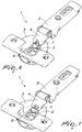
Figure 1 is a perspective view of the hinge according to the invention with the deactivation device in the deceleration activation position; -
Figure 2 is a perspective view of the hinge inFigure 1 with the deactivation device in the position of at least partial deactivation of deceleration; -
Figure 3 is a partially cross-sectional side elevation view of the hinge inFigures 1 and 2 , with the deceleration deactivation device in the deceleration activation condition; -
Figure 4 is a partially cross-sectional side elevation view of the hinge inFigures 1 and 2 , with the deceleration deactivation device in the deceleration deactivation condition; -
Figure 5 is an exploded perspective view of the deceleration deactivation device according to the invention according to a first embodiment thereof; -
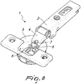
Figure 6 is a perspective view of the hinge according to the invention with the deceleration deactivation device according to a second embodiment thereof, in the deceleration activation condition; -
Figure 7 is a perspective view of the hinge ofFigure 6 , with the deceleration deactivation device in the condition of partial deactivation of deceleration; -
Figure 8 is a perspective view of the hinge ofFigure 6 , with the deceleration deactivation device in the deceleration deactivation condition. - With reference to the figures, the hinge according to the invention, generally designated by the
reference numeral 1, comprises afixed part 2 or arm of the hinge, which can be connected to the body of a piece of furniture, and amoveable part 3, which is constituted by a box and can be connected to the door leaf of the piece of furniture. Thefixed part 2 and themoveable part 3 are mutually connected by way of a system of articulation that comprises at least oneoscillating rocker 4, preferentially afirst rocker 4 and asecond rocker 9 which define an articulated quadrilateral kinematic mechanism together withrespective pins moveable part 3 and to thefixed part 2 of the hinge. - The hinge according to the invention has means of deceleration which comprise a
deceleration disk 8 which interacts with viscous means and is actuated by anactuation element 6, which can conveniently be functionally mated to or uncoupled from therocker 4. - In particular, the coupling between the
actuation element 6 and therocker 4 occurs by way of adapted cam means 5 which are supported so that they can oscillate on theoscillation pin 10 between therocker 4 and thebox 3 and can be made integral or otherwise with therocker 4. - The coupling between the cam means 5 and the
rocker 4 occurs by way ofmeans 7 for at least partial deactivation of deceleration, which comprise an element for locking thecam 5, such locking element being supported so that it can move on therocker 4. - In a first embodiment, illustrated in
Figures 1 to 5 , the deactivation means 7 are supported so that they are linearly slideable, transversely, with respect to therocker 4. - The deactivation means 7 can be moved from a first, activation position,
Fig. 1 , in which thecam 5 is integral in its movement with therocker 4, and a second, deceleration deactivation position,Fig. 2 , in which thecam 5 is free to oscillate with respect to therocker 4. - As shown in the figures, in the deactivation position, the
cam 5, being free to oscillate, is not capable of driving any movement or it drives in any case only a partial movement of theslideable actuation element 6 of thedeceleration disk 8, thus completely or partially deactivating the decelerating effect. - By contrast, in the activation position, because the
cam 5 is integral with therocker 4, the hinge behaves like a normal decelerated hinge, lacking the deactivation means 7 described previously. -
Figure 6 shows a second embodiment of the hinge according to the invention, in which the deactivation means 7 are constituted by a rotary element that is contoured so as to define a deceleration activation position, similarly to what is shown inFigure 1 , a deceleration deactivation position, shown inFigure 8 , similarly to what is shown inFigure 2 , and preferentially at least one intermediate position,Figure 7 , in which the deceleration is only partially deactivated. - Alternatively, the rotary element can have a surface that is eccentric with respect to the rotation axis of their rotary motion, so as to continuously define the position of the cam with respect to the rocker.
- The deactivation means described and shown above can also be used in hinges that have a different deceleration device, for example if, in place of the
deceleration disk 8 embedded in the grease, there is at least one oil-operated or fluid-operated linear decelerator, functionally connected to theslideable actuation element 6. - In practice it has been found that the hinge according to the present invention fully achieves the set aim and objects, in that it makes it possible to deactivate at least partially the deceleration device coupled to the hinge proper, so as to enable the user to decide if he/she wants the travel of the door leaf to which the hinge is applied to be decelerated or not, or be partially decelerated.
- The hinge, thus conceived, is susceptible of numerous modifications and variations, all of which are within the scope of the appended claims.
- Where technical features mentioned in any claim are followed by reference signs, those reference signs have been included for the sole purpose of increasing the intelligibility of the claims and accordingly, such reference signs do not have any limiting effect on the interpretation of each element identified by way of example by such reference signs.
Claims (11)
- A hinge (1) for pieces of furniture with deceleration device, comprising a fixed part (2) which is adapted to be connected to the body of a piece of furniture, a moveable part (3) which is adapted to be connected to a leaf of said piece of furniture, said fixed part (2) and said movable part (3) being mutually articulated by way of at least one connecting oscillating rocker (4, 9), deceleration means (8) being further provided which are coupled functionally to said oscillating rocker (4), said deceleration means (8) comprising means (7) for at least partial deactivation of deceleration, said means (7) for at least partial deactivation of deceleration being adapted to uncouple said oscillating rocker (4) from said deceleration means (8), characterized in that said deceleration means comprise a deceleration element (8) which can be actuated by a slidable actuation element (6), it being possible to functionally mate said actuation element (6) with said rocker (4) by way of cam means (5) which can move with respect to said rocker (4), said means (7) of deactivation of deceleration comprising an element for locking said cam means (5) with respect to said rocker (4).
- The hinge according to claim 1, characterized in that said cam means (5) are supported so that they can oscillate on an oscillation pin (10) between said oscillating rocker (4) and said moveable part (3), said cam means (5) being integrally connectable to said oscillating rocker (4).
- The hinge according to claim 2, characterized in that said cam means (5) and said oscillating rocker (4) can be connected to each other by way of said element for locking said deactivation means (7).
- The hinge according to one or more of the preceding claims, characterized in that said deactivation means (7) can move from a position for deactivating the deceleration element (8), in which said cam means (5) oscillate freely with respect to said oscillating rocker (4), to a position for activating the deceleration element (8), in which said cam means (5) are integrally connected to said rocker (4).
- The hinge according to one or more of the preceding claims, characterized in that said deactivation means (7) can move through at least one intermediate position between said deceleration deactivation position and said deceleration activation position.
- The hinge according to one or more of the preceding claims, characterized in that said deceleration element (8) is a deceleration disk that interacts with viscous means.
- The hinge according to one or more of the preceding claims, characterized in that said deceleration element is an oil-operated or fluid-operated linear decelerator.
- The hinge according to one or more of the preceding claims, characterized in that said deactivation means (7) are adapted to perform a linear translation motion transversely to said rocker (4).
- The hinge according to one or more of the preceding claims, characterized in that said deactivation means (7) are adapted to perform a rotary motion in order to pass from a deceleration deactivation position to a deceleration activation position.
- The hinge according to claim 9, characterized in that said deactivation means (7) have at least one intermediate position between said deceleration deactivation position and said deceleration activation position.
- The hinge according to claim 9, characterized in that said deactivation means (7) have a surface that is eccentric with respect to the rotation axis of their rotary motion.
Priority Applications (1)
| Application Number | Priority Date | Filing Date | Title |
|---|---|---|---|
| SI201531870T SI3237712T1 (en) | 2014-12-23 | 2015-12-11 | Hinge for pieces of furniture with deactivatable deceleration device |
Applications Claiming Priority (2)
| Application Number | Priority Date | Filing Date | Title |
|---|---|---|---|
| ITMI20142227 | 2014-12-23 | ||
| PCT/EP2015/079474 WO2016102216A1 (en) | 2014-12-23 | 2015-12-11 | Hinge for pieces of furniture with deactivatable deceleration device |
Publications (2)
| Publication Number | Publication Date |
|---|---|
| EP3237712A1 EP3237712A1 (en) | 2017-11-01 |
| EP3237712B1 true EP3237712B1 (en) | 2022-05-11 |
Family
ID=52574304
Family Applications (1)
| Application Number | Title | Priority Date | Filing Date |
|---|---|---|---|
| EP15808240.4A Active EP3237712B1 (en) | 2014-12-23 | 2015-12-11 | Hinge for pieces of furniture with deactivatable deceleration device |
Country Status (10)
| Country | Link |
|---|---|
| US (1) | US10240379B2 (en) |
| EP (1) | EP3237712B1 (en) |
| JP (1) | JP6709791B2 (en) |
| CN (1) | CN107109883B (en) |
| BR (1) | BR112017012574B1 (en) |
| ES (1) | ES2917983T3 (en) |
| PL (1) | PL3237712T3 (en) |
| SI (1) | SI3237712T1 (en) |
| TW (1) | TWI671462B (en) |
| WO (1) | WO2016102216A1 (en) |
Families Citing this family (1)
| Publication number | Priority date | Publication date | Assignee | Title |
|---|---|---|---|---|
| IT201800006575A1 (en) * | 2018-06-22 | 2019-12-22 | Decelerated furniture hinge. |
Family Cites Families (26)
| Publication number | Priority date | Publication date | Assignee | Title |
|---|---|---|---|---|
| DE10211294B4 (en) * | 2002-03-14 | 2013-10-17 | Grass Gmbh | Furniture fitting with brake and damping device |
| ITRM20040179U1 (en) * | 2004-11-12 | 2005-02-12 | Salice Arturo Spa | HINGE FOR FURNITURE WITH DAMPING DEVICE. |
| EP1809843B1 (en) | 2004-11-12 | 2008-02-20 | Arturo Salice S.p.A. | Furniture hinge with damping device |
| ITRM20050166U1 (en) * | 2005-12-15 | 2007-06-16 | Salice Arturo Spa | HINGE FOR MOBILE. |
| ITRM20060081U1 (en) * | 2006-05-11 | 2007-11-12 | Salice Arturo Spa | HINGE FOR MOBILE WITH DAMPING DEVICE |
| ITMI20072146A1 (en) * | 2007-11-09 | 2009-05-10 | Salice Arturo Spa | DECELERATION DEVICE FOR MOBILE HINGE AND MOBILE HINGE THAT PRESENTS THAT DECELERATION DEVICE |
| ITMI20072169A1 (en) * | 2007-11-14 | 2009-05-15 | Agostino Ferrari Spa | "SHOCK ABSORBER ASSEMBLY FOR FURNITURE HINGES" |
| US8505165B2 (en) * | 2008-01-22 | 2013-08-13 | Grass America, Inc. | Damping mechanism for cabinet hinge assembly |
| AT506643A1 (en) * | 2008-04-11 | 2009-10-15 | Blum Gmbh Julius | DAMPING DEVICE FOR VAPORING AN OPENING AND / OR CLOSING MOVEMENT OF A FURNITURE FITTING |
| AT507697B1 (en) * | 2008-12-17 | 2011-12-15 | Blum Gmbh Julius | FURNITURE HINGE WITH ROTARY DAMPER |
| AT508068B1 (en) * | 2009-03-25 | 2016-11-15 | Blum Gmbh Julius | FURNITURE HINGE |
| AT508070A1 (en) * | 2009-03-25 | 2010-10-15 | Blum Gmbh Julius | FURNITURE HINGE |
| GB2469846B (en) * | 2009-04-29 | 2013-12-11 | Lama D D Dekani | Improvements in hinge assemblies |
| ITMI20101155A1 (en) | 2010-06-25 | 2011-12-26 | Salice Arturo Spa | DECELERATION DEVICE |
| AT509720B1 (en) * | 2010-08-23 | 2011-11-15 | Blum Gmbh Julius | DAMPING DEVICE FOR FURNITURE PARTS |
| AT510375B1 (en) * | 2010-08-27 | 2018-06-15 | Blum Gmbh Julius | FURNITURE SHOCKS |
| CN102587757B (en) * | 2011-01-12 | 2014-10-22 | 昆山湖华金属制品有限公司 | Hinge with buffer device |
| DE102011050053A1 (en) * | 2011-05-03 | 2012-11-08 | Hettich-Oni Gmbh & Co. Kg | hinge |
| DE202012003508U1 (en) * | 2012-04-05 | 2013-07-08 | Grass Gmbh | Device for a movable furniture part and furniture |
| ITMI20121122A1 (en) * | 2012-06-26 | 2013-12-27 | Salice Arturo Spa | DECELERATED HINGE FOR FURNITURE |
| US8561262B1 (en) * | 2012-12-19 | 2013-10-22 | King Slide Works Co., Ltd. | Damping device for hinge assembly |
| EP2746509B1 (en) * | 2012-12-20 | 2016-10-19 | King Slide Works Co., Ltd. | Damping device for hinge assembly |
| US8650711B1 (en) * | 2013-01-04 | 2014-02-18 | King Slide Works Co., Ltd. | Hinge assembly with damping device |
| CN203308270U (en) * | 2013-06-04 | 2013-11-27 | 广东泰明金属制品有限公司 | Damper device for furniture hinge |
| CN103711393B (en) * | 2014-01-03 | 2016-02-17 | 伍志勇 | A kind of hinge means of lockable buffer switch position |
| US9163447B1 (en) * | 2014-09-18 | 2015-10-20 | King Slide Works Co., Ltd. | Hinge with damping device |
-
2015
- 2015-12-11 CN CN201580070425.2A patent/CN107109883B/en active Active
- 2015-12-11 US US15/538,835 patent/US10240379B2/en active Active
- 2015-12-11 SI SI201531870T patent/SI3237712T1/en unknown
- 2015-12-11 ES ES15808240T patent/ES2917983T3/en active Active
- 2015-12-11 EP EP15808240.4A patent/EP3237712B1/en active Active
- 2015-12-11 BR BR112017012574-9A patent/BR112017012574B1/en active IP Right Grant
- 2015-12-11 WO PCT/EP2015/079474 patent/WO2016102216A1/en active Application Filing
- 2015-12-11 PL PL15808240.4T patent/PL3237712T3/en unknown
- 2015-12-11 JP JP2017534719A patent/JP6709791B2/en active Active
- 2015-12-21 TW TW104142909A patent/TWI671462B/en active
Also Published As
| Publication number | Publication date |
|---|---|
| BR112017012574B1 (en) | 2022-04-12 |
| JP6709791B2 (en) | 2020-06-17 |
| US20180010378A1 (en) | 2018-01-11 |
| JP2018504538A (en) | 2018-02-15 |
| CN107109883A (en) | 2017-08-29 |
| TWI671462B (en) | 2019-09-11 |
| SI3237712T1 (en) | 2022-10-28 |
| WO2016102216A1 (en) | 2016-06-30 |
| TW201632707A (en) | 2016-09-16 |
| BR112017012574A2 (en) | 2018-02-20 |
| EP3237712A1 (en) | 2017-11-01 |
| CN107109883B (en) | 2019-01-11 |
| ES2917983T3 (en) | 2022-07-12 |
| PL3237712T3 (en) | 2022-10-03 |
| US10240379B2 (en) | 2019-03-26 |
Similar Documents
| Publication | Publication Date | Title |
|---|---|---|
| JP6611828B2 (en) | Furniture hinges | |
| EP3575532B1 (en) | Lifting system for leaves of furniture | |
| JP6412885B2 (en) | Multi-link hinge with buffer function | |
| US10808442B2 (en) | Decelerated hinge for pieces of furniture | |
| JP6871939B2 (en) | Hinge with elastic opening means used for furniture doors | |
| US20160032636A1 (en) | American damper concealed hinge | |
| US11414908B2 (en) | Decelerated hinge for furniture | |
| TW201311991A (en) | Hinge | |
| US10526827B2 (en) | Hinge for furniture leaves that open downwardly | |
| JP2020528977A (en) | Furniture hinges with door opening device | |
| EP3237712B1 (en) | Hinge for pieces of furniture with deactivatable deceleration device | |
| EP2761118B1 (en) | Safety device to prevent the sudden closing of a movable element | |
| US11946304B2 (en) | Hinge for furniture |
Legal Events
| Date | Code | Title | Description |
|---|---|---|---|
| STAA | Information on the status of an ep patent application or granted ep patent |
Free format text: STATUS: THE INTERNATIONAL PUBLICATION HAS BEEN MADE |
|
| PUAI | Public reference made under article 153(3) epc to a published international application that has entered the european phase |
Free format text: ORIGINAL CODE: 0009012 |
|
| STAA | Information on the status of an ep patent application or granted ep patent |
Free format text: STATUS: REQUEST FOR EXAMINATION WAS MADE |
|
| 17P | Request for examination filed |
Effective date: 20170710 |
|
| AK | Designated contracting states |
Kind code of ref document: A1 Designated state(s): AL AT BE BG CH CY CZ DE DK EE ES FI FR GB GR HR HU IE IS IT LI LT LU LV MC MK MT NL NO PL PT RO RS SE SI SK SM TR |
|
| AX | Request for extension of the european patent |
Extension state: BA ME |
|
| DAV | Request for validation of the european patent (deleted) | ||
| DAX | Request for extension of the european patent (deleted) | ||
| STAA | Information on the status of an ep patent application or granted ep patent |
Free format text: STATUS: EXAMINATION IS IN PROGRESS |
|
| 17Q | First examination report despatched |
Effective date: 20180808 |
|
| STAA | Information on the status of an ep patent application or granted ep patent |
Free format text: STATUS: EXAMINATION IS IN PROGRESS |
|
| GRAP | Despatch of communication of intention to grant a patent |
Free format text: ORIGINAL CODE: EPIDOSNIGR1 |
|
| STAA | Information on the status of an ep patent application or granted ep patent |
Free format text: STATUS: GRANT OF PATENT IS INTENDED |
|
| INTG | Intention to grant announced |
Effective date: 20220204 |
|
| GRAS | Grant fee paid |
Free format text: ORIGINAL CODE: EPIDOSNIGR3 |
|
| GRAA | (expected) grant |
Free format text: ORIGINAL CODE: 0009210 |
|
| STAA | Information on the status of an ep patent application or granted ep patent |
Free format text: STATUS: THE PATENT HAS BEEN GRANTED |
|
| AK | Designated contracting states |
Kind code of ref document: B1 Designated state(s): AL AT BE BG CH CY CZ DE DK EE ES FI FR GB GR HR HU IE IS IT LI LT LU LV MC MK MT NL NO PL PT RO RS SE SI SK SM TR |
|
| REG | Reference to a national code |
Ref country code: GB Ref legal event code: FG4D |
|
| REG | Reference to a national code |
Ref country code: CH Ref legal event code: EP |
|
| REG | Reference to a national code |
Ref country code: AT Ref legal event code: REF Ref document number: 1491545 Country of ref document: AT Kind code of ref document: T Effective date: 20220515 |
|
| REG | Reference to a national code |
Ref country code: DE Ref legal event code: R096 Ref document number: 602015078940 Country of ref document: DE |
|
| REG | Reference to a national code |
Ref country code: IE Ref legal event code: FG4D |
|
| REG | Reference to a national code |
Ref country code: ES Ref legal event code: FG2A Ref document number: 2917983 Country of ref document: ES Kind code of ref document: T3 Effective date: 20220712 |
|
| REG | Reference to a national code |
Ref country code: LT Ref legal event code: MG9D |
|
| REG | Reference to a national code |
Ref country code: NL Ref legal event code: MP Effective date: 20220511 |
|
| PG25 | Lapsed in a contracting state [announced via postgrant information from national office to epo] |
Ref country code: SE Free format text: LAPSE BECAUSE OF FAILURE TO SUBMIT A TRANSLATION OF THE DESCRIPTION OR TO PAY THE FEE WITHIN THE PRESCRIBED TIME-LIMIT Effective date: 20220511 Ref country code: PT Free format text: LAPSE BECAUSE OF FAILURE TO SUBMIT A TRANSLATION OF THE DESCRIPTION OR TO PAY THE FEE WITHIN THE PRESCRIBED TIME-LIMIT Effective date: 20220912 Ref country code: NO Free format text: LAPSE BECAUSE OF FAILURE TO SUBMIT A TRANSLATION OF THE DESCRIPTION OR TO PAY THE FEE WITHIN THE PRESCRIBED TIME-LIMIT Effective date: 20220811 Ref country code: NL Free format text: LAPSE BECAUSE OF FAILURE TO SUBMIT A TRANSLATION OF THE DESCRIPTION OR TO PAY THE FEE WITHIN THE PRESCRIBED TIME-LIMIT Effective date: 20220511 Ref country code: LT Free format text: LAPSE BECAUSE OF FAILURE TO SUBMIT A TRANSLATION OF THE DESCRIPTION OR TO PAY THE FEE WITHIN THE PRESCRIBED TIME-LIMIT Effective date: 20220511 Ref country code: HR Free format text: LAPSE BECAUSE OF FAILURE TO SUBMIT A TRANSLATION OF THE DESCRIPTION OR TO PAY THE FEE WITHIN THE PRESCRIBED TIME-LIMIT Effective date: 20220511 Ref country code: GR Free format text: LAPSE BECAUSE OF FAILURE TO SUBMIT A TRANSLATION OF THE DESCRIPTION OR TO PAY THE FEE WITHIN THE PRESCRIBED TIME-LIMIT Effective date: 20220812 Ref country code: FI Free format text: LAPSE BECAUSE OF FAILURE TO SUBMIT A TRANSLATION OF THE DESCRIPTION OR TO PAY THE FEE WITHIN THE PRESCRIBED TIME-LIMIT Effective date: 20220511 Ref country code: BG Free format text: LAPSE BECAUSE OF FAILURE TO SUBMIT A TRANSLATION OF THE DESCRIPTION OR TO PAY THE FEE WITHIN THE PRESCRIBED TIME-LIMIT Effective date: 20220811 |
|
| PG25 | Lapsed in a contracting state [announced via postgrant information from national office to epo] |
Ref country code: RS Free format text: LAPSE BECAUSE OF FAILURE TO SUBMIT A TRANSLATION OF THE DESCRIPTION OR TO PAY THE FEE WITHIN THE PRESCRIBED TIME-LIMIT Effective date: 20220511 Ref country code: LV Free format text: LAPSE BECAUSE OF FAILURE TO SUBMIT A TRANSLATION OF THE DESCRIPTION OR TO PAY THE FEE WITHIN THE PRESCRIBED TIME-LIMIT Effective date: 20220511 Ref country code: IS Free format text: LAPSE BECAUSE OF FAILURE TO SUBMIT A TRANSLATION OF THE DESCRIPTION OR TO PAY THE FEE WITHIN THE PRESCRIBED TIME-LIMIT Effective date: 20220911 |
|
| PG25 | Lapsed in a contracting state [announced via postgrant information from national office to epo] |
Ref country code: SM Free format text: LAPSE BECAUSE OF FAILURE TO SUBMIT A TRANSLATION OF THE DESCRIPTION OR TO PAY THE FEE WITHIN THE PRESCRIBED TIME-LIMIT Effective date: 20220511 Ref country code: SK Free format text: LAPSE BECAUSE OF FAILURE TO SUBMIT A TRANSLATION OF THE DESCRIPTION OR TO PAY THE FEE WITHIN THE PRESCRIBED TIME-LIMIT Effective date: 20220511 Ref country code: RO Free format text: LAPSE BECAUSE OF FAILURE TO SUBMIT A TRANSLATION OF THE DESCRIPTION OR TO PAY THE FEE WITHIN THE PRESCRIBED TIME-LIMIT Effective date: 20220511 Ref country code: EE Free format text: LAPSE BECAUSE OF FAILURE TO SUBMIT A TRANSLATION OF THE DESCRIPTION OR TO PAY THE FEE WITHIN THE PRESCRIBED TIME-LIMIT Effective date: 20220511 Ref country code: DK Free format text: LAPSE BECAUSE OF FAILURE TO SUBMIT A TRANSLATION OF THE DESCRIPTION OR TO PAY THE FEE WITHIN THE PRESCRIBED TIME-LIMIT Effective date: 20220511 |
|
| REG | Reference to a national code |
Ref country code: DE Ref legal event code: R097 Ref document number: 602015078940 Country of ref document: DE |
|
| PGFP | Annual fee paid to national office [announced via postgrant information from national office to epo] |
Ref country code: PL Payment date: 20221125 Year of fee payment: 8 |
|
| PLBE | No opposition filed within time limit |
Free format text: ORIGINAL CODE: 0009261 |
|
| STAA | Information on the status of an ep patent application or granted ep patent |
Free format text: STATUS: NO OPPOSITION FILED WITHIN TIME LIMIT |
|
| PG25 | Lapsed in a contracting state [announced via postgrant information from national office to epo] |
Ref country code: AL Free format text: LAPSE BECAUSE OF FAILURE TO SUBMIT A TRANSLATION OF THE DESCRIPTION OR TO PAY THE FEE WITHIN THE PRESCRIBED TIME-LIMIT Effective date: 20220511 |
|
| 26N | No opposition filed |
Effective date: 20230214 |
|
| PGFP | Annual fee paid to national office [announced via postgrant information from national office to epo] |
Ref country code: ES Payment date: 20230102 Year of fee payment: 8 |
|
| PGFP | Annual fee paid to national office [announced via postgrant information from national office to epo] |
Ref country code: DE Payment date: 20221228 Year of fee payment: 8 |
|
| P01 | Opt-out of the competence of the unified patent court (upc) registered |
Effective date: 20230515 |
|
| REG | Reference to a national code |
Ref country code: CH Ref legal event code: PL |
|
| REG | Reference to a national code |
Ref country code: AT Ref legal event code: UEP Ref document number: 1491545 Country of ref document: AT Kind code of ref document: T Effective date: 20220511 |
|
| GBPC | Gb: european patent ceased through non-payment of renewal fee |
Effective date: 20221211 |
|
| REG | Reference to a national code |
Ref country code: BE Ref legal event code: MM Effective date: 20221231 |
|
| PG25 | Lapsed in a contracting state [announced via postgrant information from national office to epo] |
Ref country code: LU Free format text: LAPSE BECAUSE OF NON-PAYMENT OF DUE FEES Effective date: 20221211 |
|
| PG25 | Lapsed in a contracting state [announced via postgrant information from national office to epo] |
Ref country code: LI Free format text: LAPSE BECAUSE OF NON-PAYMENT OF DUE FEES Effective date: 20221231 Ref country code: IE Free format text: LAPSE BECAUSE OF NON-PAYMENT OF DUE FEES Effective date: 20221211 Ref country code: GB Free format text: LAPSE BECAUSE OF NON-PAYMENT OF DUE FEES Effective date: 20221211 Ref country code: CH Free format text: LAPSE BECAUSE OF NON-PAYMENT OF DUE FEES Effective date: 20221231 |
|
| PG25 | Lapsed in a contracting state [announced via postgrant information from national office to epo] |
Ref country code: FR Free format text: LAPSE BECAUSE OF NON-PAYMENT OF DUE FEES Effective date: 20221231 Ref country code: BE Free format text: LAPSE BECAUSE OF NON-PAYMENT OF DUE FEES Effective date: 20221231 |
|
| PGFP | Annual fee paid to national office [announced via postgrant information from national office to epo] |
Ref country code: SI Payment date: 20231121 Year of fee payment: 9 Ref country code: IT Payment date: 20231220 Year of fee payment: 9 Ref country code: CZ Payment date: 20231124 Year of fee payment: 9 Ref country code: AT Payment date: 20231121 Year of fee payment: 9 |
|
| PGFP | Annual fee paid to national office [announced via postgrant information from national office to epo] |
Ref country code: PL Payment date: 20231124 Year of fee payment: 9 |
|
| PG25 | Lapsed in a contracting state [announced via postgrant information from national office to epo] |
Ref country code: HU Free format text: LAPSE BECAUSE OF FAILURE TO SUBMIT A TRANSLATION OF THE DESCRIPTION OR TO PAY THE FEE WITHIN THE PRESCRIBED TIME-LIMIT; INVALID AB INITIO Effective date: 20151211 |