EP3236874B1 - Systeme d'orientation chirurgical - Google Patents
Systeme d'orientation chirurgical Download PDFInfo
- Publication number
- EP3236874B1 EP3236874B1 EP15823367.6A EP15823367A EP3236874B1 EP 3236874 B1 EP3236874 B1 EP 3236874B1 EP 15823367 A EP15823367 A EP 15823367A EP 3236874 B1 EP3236874 B1 EP 3236874B1
- Authority
- EP
- European Patent Office
- Prior art keywords
- ancillary
- contact
- orientation
- point
- area
- Prior art date
- Legal status (The legal status is an assumption and is not a legal conclusion. Google has not performed a legal analysis and makes no representation as to the accuracy of the status listed.)
- Active
Links
Images



Classifications
-
- A—HUMAN NECESSITIES
- A61—MEDICAL OR VETERINARY SCIENCE; HYGIENE
- A61B—DIAGNOSIS; SURGERY; IDENTIFICATION
- A61B17/00—Surgical instruments, devices or methods
- A61B17/16—Instruments for performing osteoclasis; Drills or chisels for bones; Trepans
- A61B17/17—Guides or aligning means for drills, mills, pins or wires
- A61B17/1739—Guides or aligning means for drills, mills, pins or wires specially adapted for particular parts of the body
- A61B17/1757—Guides or aligning means for drills, mills, pins or wires specially adapted for particular parts of the body for the spine
-
- A—HUMAN NECESSITIES
- A61—MEDICAL OR VETERINARY SCIENCE; HYGIENE
- A61B—DIAGNOSIS; SURGERY; IDENTIFICATION
- A61B34/00—Computer-aided surgery; Manipulators or robots specially adapted for use in surgery
- A61B34/20—Surgical navigation systems; Devices for tracking or guiding surgical instruments, e.g. for frameless stereotaxis
-
- A—HUMAN NECESSITIES
- A61—MEDICAL OR VETERINARY SCIENCE; HYGIENE
- A61B—DIAGNOSIS; SURGERY; IDENTIFICATION
- A61B90/00—Instruments, implements or accessories specially adapted for surgery or diagnosis and not covered by any of the groups A61B1/00 - A61B50/00, e.g. for luxation treatment or for protecting wound edges
- A61B90/10—Instruments, implements or accessories specially adapted for surgery or diagnosis and not covered by any of the groups A61B1/00 - A61B50/00, e.g. for luxation treatment or for protecting wound edges for stereotaxic surgery, e.g. frame-based stereotaxis
-
- A—HUMAN NECESSITIES
- A61—MEDICAL OR VETERINARY SCIENCE; HYGIENE
- A61B—DIAGNOSIS; SURGERY; IDENTIFICATION
- A61B90/00—Instruments, implements or accessories specially adapted for surgery or diagnosis and not covered by any of the groups A61B1/00 - A61B50/00, e.g. for luxation treatment or for protecting wound edges
- A61B90/36—Image-producing devices or illumination devices not otherwise provided for
- A61B90/37—Surgical systems with images on a monitor during operation
-
- A—HUMAN NECESSITIES
- A61—MEDICAL OR VETERINARY SCIENCE; HYGIENE
- A61B—DIAGNOSIS; SURGERY; IDENTIFICATION
- A61B34/00—Computer-aided surgery; Manipulators or robots specially adapted for use in surgery
- A61B34/20—Surgical navigation systems; Devices for tracking or guiding surgical instruments, e.g. for frameless stereotaxis
- A61B2034/2046—Tracking techniques
- A61B2034/2048—Tracking techniques using an accelerometer or inertia sensor
-
- A—HUMAN NECESSITIES
- A61—MEDICAL OR VETERINARY SCIENCE; HYGIENE
- A61B—DIAGNOSIS; SURGERY; IDENTIFICATION
- A61B34/00—Computer-aided surgery; Manipulators or robots specially adapted for use in surgery
- A61B34/20—Surgical navigation systems; Devices for tracking or guiding surgical instruments, e.g. for frameless stereotaxis
- A61B2034/2046—Tracking techniques
- A61B2034/2051—Electromagnetic tracking systems
-
- A—HUMAN NECESSITIES
- A61—MEDICAL OR VETERINARY SCIENCE; HYGIENE
- A61B—DIAGNOSIS; SURGERY; IDENTIFICATION
- A61B34/00—Computer-aided surgery; Manipulators or robots specially adapted for use in surgery
- A61B34/20—Surgical navigation systems; Devices for tracking or guiding surgical instruments, e.g. for frameless stereotaxis
- A61B2034/2046—Tracking techniques
- A61B2034/2055—Optical tracking systems
-
- A—HUMAN NECESSITIES
- A61—MEDICAL OR VETERINARY SCIENCE; HYGIENE
- A61B—DIAGNOSIS; SURGERY; IDENTIFICATION
- A61B34/00—Computer-aided surgery; Manipulators or robots specially adapted for use in surgery
- A61B34/20—Surgical navigation systems; Devices for tracking or guiding surgical instruments, e.g. for frameless stereotaxis
- A61B2034/2068—Surgical navigation systems; Devices for tracking or guiding surgical instruments, e.g. for frameless stereotaxis using pointers, e.g. pointers having reference marks for determining coordinates of body points
-
- A—HUMAN NECESSITIES
- A61—MEDICAL OR VETERINARY SCIENCE; HYGIENE
- A61B—DIAGNOSIS; SURGERY; IDENTIFICATION
- A61B90/00—Instruments, implements or accessories specially adapted for surgery or diagnosis and not covered by any of the groups A61B1/00 - A61B50/00, e.g. for luxation treatment or for protecting wound edges
- A61B90/06—Measuring instruments not otherwise provided for
- A61B2090/067—Measuring instruments not otherwise provided for for measuring angles
- A61B2090/068—Measuring instruments not otherwise provided for for measuring angles with a bubble level
-
- A—HUMAN NECESSITIES
- A61—MEDICAL OR VETERINARY SCIENCE; HYGIENE
- A61B—DIAGNOSIS; SURGERY; IDENTIFICATION
- A61B90/00—Instruments, implements or accessories specially adapted for surgery or diagnosis and not covered by any of the groups A61B1/00 - A61B50/00, e.g. for luxation treatment or for protecting wound edges
- A61B90/39—Markers, e.g. radio-opaque or breast lesions markers
- A61B2090/3937—Visible markers
-
- A—HUMAN NECESSITIES
- A61—MEDICAL OR VETERINARY SCIENCE; HYGIENE
- A61B—DIAGNOSIS; SURGERY; IDENTIFICATION
- A61B90/00—Instruments, implements or accessories specially adapted for surgery or diagnosis and not covered by any of the groups A61B1/00 - A61B50/00, e.g. for luxation treatment or for protecting wound edges
- A61B90/39—Markers, e.g. radio-opaque or breast lesions markers
- A61B2090/3983—Reference marker arrangements for use with image guided surgery
Definitions
- the present invention relates to a surgical guidance system and ancillary usable in the context of such a system.
- the internal skeletal structure of a mammal, human or animal is sometimes composed of a hundred or so bones.
- the spine is a chain of bones or vertebrae allowing flexibility and movement, while protecting nerve and vascular structures in and around the spine.
- the spine begins at the base of the skull, extends to the pelvis and is composed of four regions - cervical, thoracic, lumbar and pelvic.
- the Figures 1A, 1B respectively represent a top view and a side view of a typical vertebra 1.
- the vertebra 1 comprises: a vertebral body 2 facing forward; a vertebral foramina 3 in the form of a hole allowing the spinal cord to pass; two transverse processes 4A, 4B, oriented rearward and outward; a thorny process between transversal processes 4A, 4B and downward; two blades 6A, 6B which connect the transverse processes 4A, 4B to the spinous process 5; two pedicles 7A, 7B which connect the vertebral body 2 to the transverse processes 4A, 4B; two upper articular facets 8A (not shown), 8B and two lower articular facets 9A (not shown), 9B which allow the articulation of the vertebrae 1 between them.
- Normal or ideal vertebral alignment may be disrupted following trauma or disease, for example scoliosis.
- the vertebrae can pivot around three axes (X, Y, Z), sometimes requiring surgery to correct abnormalities and find an ideal alignment or, at least improved, the spine.
- At least two adjacent vertebrae 1 are generally fused to one another by a method in which a surgeon opens the patient, usually by the back, determines an entry point 10 and pierces holes 11 in the pedicles 7A, 7B of the vertebrae 1.
- the holes are pierced with an axial angle alpha ⁇ (the angle with respect to the plane XZ) and a sagittal angle beta ⁇ (the angle with respect to the plane XY), shown at Figures 1A, 1B respectively.
- pedicle screws 12 having U-shaped ends 13 are inserted into the holes 11.
- ends 13 receive connecting elements (not shown), for example bars, which reduce the deformation and merge the vertebrae 1 between them.
- the connecting elements are connected between the pedicle screws of two adjacent vertebrae 1 in order to correct, as and when, the alignment of the vertebral column, which is based on approximate correction objectives for each level of the column.
- all the drilled holes 11 and the pedicle screws 12 placed in the vertebrae 1 must be carefully positioned and aligned so as not to injure the adjacent nerve and vascular structures, or even cause the patient to die.
- a second operation should be carried out, entailing additional costs and risks.
- Computed tomography is a medical imaging technique performed during a preoperative phase to construct a three-dimensional model of the area to be operated, for example one or more vertebrae.
- CT Computed tomography
- optical markers arranged on the surgical tools are captured by a plurality of cameras that film the operating room in real time, in order to locate the positions of the tools relative to the model.
- the patient is usually lying on his back for taking pictures, while he is lying on his stomach for the operation.
- the positions of the vertebrae do not match between the images taken and the position of the patient during the operation.
- the patent US 8,419,746 discloses a surgical tool comprising a rod, at least two electrodes arranged on the rod, and means for measuring the impedance between the electrodes.
- An impedance change indicates a vacuum, which means that the end of the rod is out of the bone. Nevertheless, such a tool does not allow the surgeon to determine the ideal path, it only reports a wrong path a posteriori, report that may be too late.
- the patent application WO 2006/109983 discloses a first device placed on reference points of a pelvis to indicate a plane parallel to the pelvis for the insertion of an acetabulum cup.
- the patent DE 695 34862 discloses a clip attached to a bone projection and coupled to a reference frame including light-emitting diodes detectable by a camera system.
- the patent application WO 2014/176207 discloses a custom recording device that is manufactured from the preoperative images and placed on the patient during the surgical procedure.
- the patent application KR 2006 0003685 discloses a first device placed on three points of the pelvis and which works in consultation with a device fixed on the pelvis and a guide to determine the angles of one relative to the others.
- the patent application EP 2 719 353 discloses a method of manufacturing a recording template having a surface that accurately binds to a surface of a bone at a surgical target site of a patient for use in surgery guided by a medical navigation system .
- Embodiments of the invention relate to a surgical ancillary device according to independent claim 1.
- the first point of contact, the second point of contact, the contact zone, the determination means and the communication means are integrated in a single part of the ancillary.
- the first point of contact, the second point of contact and the contact zone are integrated in a first part of the ancillary, and the determination means and the communication means are integrated in a second part which can be recessed on the first part.
- the contact zone is a substantially planar tangential zone.
- the ancillary orientation reference frame enables an orientation reference of the operating zone to be determined with respect to the Galilean orientation reference system by means of a rotation matrix.
- the ancillary device further comprises means for validating the tangential contact zone.
- the tangential contact area is transparent and arranged in a grid pattern and marked to allow a surgeon to determine where exactly the tangential area is in contact with the third reference point.
- the first point, the second point, and the tangential contact zone are coplanar.
- the means for determining the orientation reference frame is a device comprising at least three non-aligned optical markers intended to be visible by at least one camera filming the operating area.
- the communication means of the orientation reference system is a visual display.
- the communication means of the orientation reference frame is a wired or non-wired link.
- Embodiments of the invention further relate to an assembly comprising at least two ancillaries according to the invention, the ancillaries being designed for operating areas different from each other.
- the ancillary and the surgical tool are capable of being coupled to the same orientation reference determination and communication device.
- Embodiments of the invention further relate to a non-transitory, computer readable medium comprising a computer executable instruction program for performing the method of the invention.
- the Figure 2A represents a SYS1 surgical guidance system according to one embodiment.
- the SYS1 system comprises a tool 20 (hereinafter "ancillary") and a surgical tool 30, for example a drill.
- ancillary a tool 20
- surgical tool 30 for example a drill.
- Ancillary device 20 comprises: at least two contact points 21, 22; a tangential plane contact zone 23; a means 24 for determining an orientation reference frame RA of the ancillary device and a means 25 for communicating the orientation reference frame RA of the ancillary device.
- the reference frame RA of the ancillary 20 can be likened to a reference frame RO of a ZO operating area (for example the vertebra 1) and therefore allows to know the reference frame RO in a referential of Galilean orientation RS, for example of an operating room ZS (shown at figure 8 ). In what follows, the RO reference referential term of the operating area will be used.
- the ancillary device 20 is Y-shaped ("i-Greek"), the points 21, 22 being rectilinear edges of a first branch 26 and a second branch 27 respectively, and a third branch 28 serving as a handle.
- the branches 26, 27 are the upper left and right ends of the Y respectively
- the branch 28 is the lower central end of the Y
- the zone 23 is disposed at the center of the Y and comprises a flat bottom face. (more or less).
- the ancillary device 20 further comprises "pins" 29 on the points 21, 22 which prevent the ancillary 20 from sliding once in contact with the vertebra.
- the points 21, 22 and the plane contact zone 23 are coplanar.
- the operating zone ZO (here vertebra 1) comprises at least three reference points R1, R2, R3.
- the points R1, R2 are arranged for example at the top of the transverse processes 4A, 4B respectively, and are fairly easy to identify with the naked eye, in particular by an experienced surgeon.
- the point R3 is arranged on the spinous process 5 in a tangential zone ZT, as will be explained later.
- the contact points 21, 22 are each intended to come into contact with the points R1, R2 respectively and the zone 23 is placed on the point R3 in order to determine a coordinate system or "reference frame of reference" RO of the operating zone ZO with respect to the reference frame RS of the operating theater ZS.
- the surgical tool 30 is for example a tool for piercing the vertebra 1, and comprises: a rod 31; a point 32 at the front end of the stem; a handle 33; means 34 for determining an orientation reference frame RT of the tool; and means for communicating the orientation reference frame RT of the tool.
- the determination means 24, 34 are bubble levels, also sometimes called level
- the communication means 25, 36 are visual indicators, for example numbers marked around the spirit level or even a simple circle in the center of the level.
- the Figures 3A, 3B respectively represent a top view and a side view of the ancillary 20 placed on a vertebra 1.
- the dimensions of the ancillary 20 are adapted to the intended application, for example about 10 cm wide, 15 cm of length, and 0.50 cm thick for operations on the human spine.
- the reference points R1, R2, R3 are determined to define the orientation reference frame RO of the operating zone.
- the point R3 is a point in the tangential zone ZT, which will be more difficult to determine with the naked eye but will be contacted by the contact zone 23 by simply placing the ancillary on the ZT zone.
- grasping the optimal screwing directions of the pedicle screws 12 makes it possible to define a director vector for each pedicle screw.
- each reference frame RO, RS comprises three axes, Xo, Yo, Zo; Xs, Ys, Zs respectively.
- An arrow [V] ro (or "local reference") represents a director vector V of a surgical gesture (for example the installation of a pedicle screw) expressed in the OR orientation reference frame of the operating zone (currently in the vertebrate).
- the OR referral repository of the operating area is not necessarily aligned with the OR repository of the OR, as shown in figure 4 .
- the surgeon positions the ancillary 20 on the vertebra 1, as shown in FIG. Figures 3A, 3B placing the points 21, 22 in contact with the reference points R1, R2 respectively, and then placing the zone 23 on the reference point R3.
- the orientation reference frame RO of the operating zone ZO is then determined with respect to the reference frame RS of the operating room, by means of determination and communication means 24, 25 of the reference frame RO of the operating zone ZO.
- a Mrors rotation matrix which expresses the orientation reference frame RO in the orientation reference frame RS, is defined.
- the surgical tool 30 determines and communicates, thanks to the determination and communication means 34, 35 of the reference frame RT of the tool, in real time its orientation, in particular the orientation of its rod 31, in the Repository of orientation RS of the operating room.
- the dynamic orientation of the rod 31 relative to the ideal orientation of the pedicle screw to be laid, allows the surgeon to adapt the orientation of the tool 30 to match the orientation of the vector director [V] ro expressed in the Galilean referential RS (ie [V] rs).
- the Figures 5A, 5B represent respectively a perspective view and a top view of a SYS2 surgical guidance system according to an example.
- the SYS2 system includes an ancillary 40 and a surgical tool (not shown for simplicity).
- Ancillary 40 comprises: at least two contact points 41, 42; a tangential contact area or "flat palpation plateau"43; determination means 44 of the orientation reference frame RA (and consequently RO) and a communication means 45 of the orientation reference frame (not shown in detail).
- the ancillary device 40 is in the form of a "compass", the points 41, 42 being the lower ends of the branches 46, 47 arranged along a transverse axis A-A ', and the contact zone 43 being disposed at the lower end of a third leg 48 arranged along a longitudinal axis BB 'which bisects the axis AA' to a central vertical axis CC 'and also serves as a handle.
- the determining means 44 is a "MEMS" or “electromechanical microsystem” system which determines the plane of the ancillary.
- This means may comprise a tri-axis accelerometer, a tri-axis magnetometer, and / or a tri-axis gyroscope, as known to those skilled in the art and will not be explained in more detail.
- the communication means 45 is a wired link (cable) or non-wired (non-contact), for example by Wi-Fi or Bluetooth.
- the vertebrae on which one operates may vary from the "typical" vertebra shown on the figure 1 , depending on the reason of the operation, the age of the patient, his morphology, etc.
- the reference points R1, R2, R3 may be out of step with the standards.
- the lengths of the branches 46, 47 can be adjusted along the axis A'A 'to take into account possible variations in the size of the vertebrae.
- the ancillary comprises a pinion 49 for adjusting the lengths of the branches 46, 47, which comprise adjustment rails.
- the length of the branch 48 can be adjusted along the axis BB 'for example by means of a "telescopic" system, as well as the angles of the branches 46, 47, 48 with respect to the center, inclination of the branches relative to the plane formed by the axes A-A ', B-B', etc.
- the ancillary 40 is placed on a vertebra 1 in the intraoperative phase.
- the points 41, 42 of the branches 47, 48 are placed on the reference points R1, R2.
- An axis A1-A1 ' is formed between the points. If necessary, the distance between the points 41, 42 is modified by the pinion 49.
- the ancillary is pivoted about the axis A1-A1 'so that the contact zone 43 is placed on the point R3.
- the points 41, 42 and the contact zone 43 are then coplanar.
- the orientation reference frame RO of the operating zone ZO is determined by the determination means 44 and communicated outside the ancillary 40 by the means of communication 45.
- the surgeon proceeds to drill the holes using the surgical tool, which may be similar to the tool 30 described in connection with the Figure 2A , or may comprise MEMS determination means and wired or non-wired (non-contact) communication, as described in connection with the ancillary 40.
- the figure 6 represents a top view of a SYS3 surgical guidance system according to another embodiment.
- the SYS3 system includes an ancillary device 50 and a surgical tool (not shown for the sake of simplicity).
- the ancillary device 50 comprises: at least two contact points 51, 52; a tangential contact area 53; and determining and communicating means 54-55A, 54-55B, 54-55C of the RA reference frame (RO).
- the means 54-55A, 54-55B, 54-55C are non-aligned optical markers and intended to be picked up by a plurality of cameras that film the operating room ZS in real time, in order to locate the positions of the tools by compared to the model.
- the ancillary 50 is Y-shaped ("i-Greek"), the points 51, 52 being rectilinear edges of a first branch 56 and a second branch 57 respectively, and a third branch 58 serving as a handle.
- the branches 56, 57 are the upper left and right ends of the Y respectively, the branch 58 is the lower central end of the Y and the zone 53 is disposed in the center of the Y.
- the ancillary 50 further comprises "pins" 59 on the points 51, 52 which prevent the ancillary 50 from sliding once in contact with the vertebra.
- the surgical tool may be similar to the tool described in connection with the Figure 2A (Including levels), include MEMS determination means and wired or non-wired communication (non-contact) or even include optical markers.
- the surgical tool it is not mandatory for the surgical tool to include such means of determination and communication. In this case, it can be a simple conventional surgical tool.
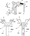
- the figure 7 represents a perspective view of a SYS4 surgical guidance system according to an example.
- the SYS4 system comprises an ancillary 60 and a surgical tool 70.
- the ancillary 60 is divided into two parts, a first part 60-1 for making contact with the operating area, and a second part 60-2 of determination and communication of the reference guide of the operating room.
- the first part 60-1 of the ancillary 60 is similar to the ancillary 40 described in connection with the Figure 5A and comprises: at least two contact points 61, 62; a tangential contact area or "palpation tray"63; branches 66, 67, 68; and an end 69 for receiving the second portion 60-2.
- the second part 60-2 comprises: a body 81; a front end 82 digs to receive the rear end 69 of the first portion 60-1; determination means 84 of the reference frame RA, RT (RO) of the part 60-1 of the ancillary 60; and a communication means 85 of the reference frame of the ancillary 60.
- the surgical tool 70 comprises: a rod 71; a point 72 at the front end of the stem; and one end behind 73.
- the ancillary 60 and the surgical tool 70 cooperate so that the second portion 60-2 of the ancillary 60 can be recessed on the first part 60-1 and the tool 70 in a non-definitive (it can be removed), precise (no play between the elements) and repeatable.
- the rear ends 69, 73 of the first portion 60-1 of the ancillary 60 and the surgical tool 70 respectively may comprise projections received in a notch inside the front end 82 hollow, causing the second portion 60-2 to be embedded in a previously defined manner.
- the second part 60-2 is first recessed on the end 69 of the first part 60-1 of the ancillary 60. Once the reference frame RA determined and communicated, the part 60-1 is set aside and the portion 60-2 is removed and placed on the end of the surgical tool 70 to determine and communicate again the orientation reference frame RT of the tool 70.
- This system allows a cost reduction because a single device Determination and repository communication is required, and can be used in the case where the operating area is not likely to change position during operation.
- the figure 8 represents a top view of a SYS5 surgical orientation system according to another embodiment.
- the SYS5 system includes an ancillary 90 and a surgical tool (not shown for the sake of simplicity).
- the ancillary 90 comprises at least two contact points 91, 92; a tangential contact area 93; means 94 for determining the orientation reference system, for example a "MEMS" system as described in connection with the Figure 5A , and communication means 95 of the orientation reference frame, for example a non-wire link (non-contact).
- orientation reference system for example a "MEMS" system as described in connection with the Figure 5A
- communication means 95 of the orientation reference frame for example a non-wire link (non-contact).
- the ancillary 90 is Y-shaped ("i-Greek"), the points 91, 92 being rectilinear edges of a first branch 96 and a second branch 97 respectively, and a third branch 98 serving as a handle.
- the branches 96, 97 are the upper left and right ends of the Y respectively, the branch 98 is the lower central end of the Y and the zone 93 is disposed in the center of the Y.
- the ancillary 90 further comprises "pins" 99 on the points 91, 92 which prevent the ancillary 90 from sliding once in contact with the vertebra.
- the ancillary 90 further comprises validation means 93A of the tangential contact zone 93.
- the zone 93 is transparent and arranged in a grid pattern and preferably marked for example by numbers (1 to 3) and letters (A to C), to allow a surgeon to determine where exactly the tangential area is in contact with the third reference point. For example, during the preoperative phase, it may be determined that the third reference point must be in contact with the zone A3 of the tangential zone.
- the pins 99 may also be equipped with markers (not shown) to facilitate the identification of the contact points.
- the validation means is a sensitive contact area which detects the contact with the third reference point, and communicates it for example by the communication means.
- the figure 9 represents an operating room ZS equipped with a surgical orientation system.
- a system SYS1 ' is shown here, comprising an ancillary 20' and a tool 30 'equipped by means of determination "MEMS" and non-wire communication means.
- the operating room ZS is equipped with a device 90 for displaying images and processing data, such as a computer.
- the device 90 comprises a screen 91, a processor 92, input and data manipulation means 93 (a keyboard, a mouse, a voice sensor, etc.), and means 94 for receiving data communicated by the user.
- input and data manipulation means 93 a keyboard, a mouse, a voice sensor, etc.
- means 94 for receiving data communicated by the user.
- the operating room further comprises an "operating entity" 100 comprising a surgeon 101 who operates on a patient 102 lying on an operating table 103.
- the screen 91 makes it possible to display images I obtained from the operating zone ZO during the preoperative phase.
- the operating room staff, and particularly the surgeon, can view the images during the operation. These images can be "static” or advantageously “dynamic". By dynamic, it is understood that the references of the ancillary 20 'and / or the surgical tool 30' are determined, communicated to the computer 90, and displayed on the screen 91 in real time. The surgeon 101 can then have a precise idea of the orientation of his tools with respect to the vertebra.
- the system is interactive and allows the surgeon 101 to give oral instructions, for example "Display the L5 vertebra. So that the computer displays the image corresponding to the L5 vertebra.
- the figure 10 represents a flowchart of a preoperative phase P1
- the figure 11 represents a flowchart of an intraoperative phase P2.
- Phase P1 comprises steps S1 to S5.
- step S1 an image I of at least one operating zone Z0 is taken, for example by means of a tomodensitometry device.
- step S2 at least three reference points R1, R2, R3 are determined and recorded in the case of a dynamic system, or simply noted in the case of a static system.
- step S3 an operating reference RO, as described above in relation to the figure 4 , is calculated using reference points and then recorded or noted.
- at least one director vector [V] ro is determined for the surgical procedure to be performed and then recorded or noted.
- step S5 the process is repeated if necessary for other operating areas.
- Phase P2 comprises steps S11 to S16.
- step S11 the operating zone ZO is exposed.
- step S12 a point of the ancillary is placed on the first reference point R1.
- step S13 another point of the ancillary is placed on the second reference point R2.
- step S14 the contact zone of the ancillary is placed on the third reference point R3.
- step S15 the orientation reference frame RO of the operating zone ZO is determined and communicated, allowing the calculation of the rotation matrix Mrors and the steering vector [V] rs.
- step S16 the surgical tool is used to perform a surgical procedure according to the calculated directional vector.
- the figure 12 is a computer readable non-transitory medium 110 and includes a computer-executable instruction program.
- the instruction program may include the calculation algorithm described in connection with the figure 4 .
- Embodiments further relate to an assembly or "kit" of at least two ancillaries 20, 20 ', 50, each ancillary being designed for ZO operating zones different from each other, for example having different dimensions, different angles between the branches, etc. This allows to cover a range of anatomical variations.
- the ancillaries 20, 20 ', 50 have different sizes, for example small, medium, and wide.
- the communication means 25, 35, 45, 55, 65 may be a digital screen, LEDs ("LED” or “Light-Emitting Diode” for example) are green, orange and red, for example. light up, wired links (a cable connected to the surgical tool or the data processing device), non-wired links (Wi-Fi, NFC, Bluetooth, etc.), an auditory signal and, more generally, any means of communication of information.
- LEDs LED or “Light-Emitting Diode” for example
- wired links a cable connected to the surgical tool or the data processing device
- non-wired links Wi-Fi, NFC, Bluetooth, etc.
- an auditory signal and, more generally, any means of communication of information.
- the contact areas 23, 43, 53, 63 have been described as essentially planar areas that arise on a tangential contact area ZT. (By "essentially flat” it is understood that the area is more or less planar within manufacturing limits). Nevertheless, it will be understood by those skilled in the art that these contact areas may have any other form designed to come into contact with a given area. For example, they may be concave to land on a rounded shape, such as spinous processes 5, convex to land in a depression, etc.
- a tool for determining and communicating an orientation reference system is attached to the operating zone ZO itself in order to continuously check its position, for example to ensure that the patient did not move during the operation, for very delicate operations.
- the position of the patient, and more particularly of the operative area, can be adjusted until the correct orientation is found.
- Means (straps, clips, etc.) for holding the operative area (the patient) in a given position can be implemented either before the operation or during the operation.
- the surgical tool is for example a perforator, a screwdriver and, in general, any tool that allows a surgical act.
- the materials used for the ancillary and the surgical tool can preferably be sterilized and do not pose a problem of biocompatibility.
- the surgical tool be provided with a position determining and communicating means.
- the surgeon can easily determine himself the correct angle, for example an angle of 90 ° with respect to the ancillary orientation reference frame.
- the branches of the ancillary 20, 20 ', 50 may be articulated around the central area, for example by means of the hinges arranged between the central zone and each branch.
Landscapes
- Health & Medical Sciences (AREA)
- Surgery (AREA)
- Life Sciences & Earth Sciences (AREA)
- Nuclear Medicine, Radiotherapy & Molecular Imaging (AREA)
- Engineering & Computer Science (AREA)
- Public Health (AREA)
- General Health & Medical Sciences (AREA)
- Veterinary Medicine (AREA)
- Animal Behavior & Ethology (AREA)
- Biomedical Technology (AREA)
- Heart & Thoracic Surgery (AREA)
- Medical Informatics (AREA)
- Molecular Biology (AREA)
- Oral & Maxillofacial Surgery (AREA)
- Pathology (AREA)
- Orthopedic Medicine & Surgery (AREA)
- Radiology & Medical Imaging (AREA)
- Gynecology & Obstetrics (AREA)
- Dentistry (AREA)
- Robotics (AREA)
- Surgical Instruments (AREA)
- Prostheses (AREA)
Description
- La présente invention concerne un système d'orientation chirurgical et un ancillaire utilisable dans le cadre d'un tel système.
- La structure squelettique interne d'un mammifère, humaine ou animale, est composée parfois d'une centaine d'os. La colonne vertébrale est une chaîne d'os ou de vertèbres permettant une certaine souplesse et de mouvement, tout en protégeant les structures nerveuses et vasculaires à l'intérieur et autour de la colonne vertébrale. La colonne vertébrale commence à la base du crâne, s'étend jusqu'au bassin et est composée de quatre régions - cervicale, thoracique, lombaire et pelvienne.
- Les
figures 1A, 1B représentent respectivement une vue de dessus et une vue de côté d'une vertèbre typique 1. La vertèbre 1 comprend : un corps vertébral 2 orienté vers l'avant ; un foramen vertébral 3 en forme de trou permettant à la moelle épinière de passer ; deux processus transversaux 4A, 4B, orientés vers l'arrière et vers l'extérieur ; un processus épineux 5 entre les processus transversaux 4A, 4B et orienté vers le bas ; deux lames 6A, 6B qui connectent les processus transversaux 4A, 4B au processus épineux 5 ; deux pédicules 7A, 7B qui connectent le corps vertébral 2 aux processus transversaux 4A, 4B ; deux facettes articulaires supérieures 8A (non représenté), 8B et deux facettes articulaires inférieures 9A (non représenté), 9B qui permettent l'articulation des vertèbres 1 entre-elles. - L'alignement vertébral normal ou idéal peut être perturbé suite à un traumatisme ou une maladie, par exemple la scoliose. Les vertèbres peuvent pivoter autour de trois axes (X, Y, Z), nécessitant parfois une intervention chirurgicale afin de corriger les anomalies et retrouver un alignement idéal ou, à tout le moins amélioré, de la colonne vertébrale.
- Dans ce cas, au moins deux vertèbres 1 adjacentes sont généralement fusionnées l'une à l'autre par un procédé dans lequel un chirurgien ouvre le patient, généralement par le dos, détermine un point d'entrée 10 et perce des trous 11 dans les pédicules 7A, 7B des vertèbres 1. Les trous sont percés avec un angle axial alpha α (l'angle par rapport au plan XZ) et un angle sagittal beta β (l'angle par rapport au plan XY), montrés aux
figures 1A, 1B respectivement. - Ensuite, des vis pédiculaires 12 comprenant des extrémités 13 en forme de U sont insérées dans les trous 11. (Pour des raisons de clarté de la
figure 1A , un seul point d'entrée 10, trou 11, vis pédiculaire 12, et extrémité 13 sont montrés.) Les extrémités 13 reçoivent des éléments de liaison (non montrés), par exemple des barres, qui permettent de réduire la déformation et de fusionner les vertèbres 1 entre elles. - Ensuite, les éléments de liaison sont connectés entre les vis pédiculaires de deux vertèbres 1 adjacentes afin de corriger, au fur et à mesure, l'alignement de la colonne vertébrale, qui est basée sur des objectifs de correction approximatifs pour chaque niveau de la colonne vertébrale et sont dérivées à partir d'images médicales (rayons électromagnétiques 'X', tomodensitométrie, imagerie par résonnance magnétique, etc.) prises préopératoirement, c'est-à-dire avant une intervention chirurgicale. En conséquence, tous les trous 11 percés et les vis pédiculaires 12 placées dans les vertèbres 1 doivent être soigneusement positionnés et alignés afin de ne pas blesser les structures nerveuses et vasculaires adjacentes, voire provoquer la mort du patient. Tout au moins, il faudrait procéder à une seconde opération, entraînant des coûts et des risques supplémentaires.
- Des systèmes de guidage ont été développés pour aider le chirurgien à percer les trous 11 dans la vertèbre 1 et placer précisément les vis pédiculaires 12.
- L'article « Guided pedicle screw insertion and training » de Manbachi et al. décrit un système d'orientation chirurgical basé sur la navigation optoélectronique. La tomodensitométrie, ou TDM, est une technique d'imagerie médicale réalisée pendant une phase préopératoire afin de construire un modèle en trois dimensions de la zone à opérer, par exemple une ou plusieurs vertèbres. Pendant une phase peropératoire, c'est-à-dire l'opération proprement dit, des marqueurs optiques agencés sur les outils chirurgicaux sont captés par une pluralité de caméras qui filment la salle d'opération en temps réel, afin de repérer les positions des outils par rapport au modèle.
- En outre, le patient est généralement allongé sur le dos pour la prise des images, tandis qu'il est allongé sur le ventre pour l'opération. En conséquence, les positions des vertèbres ne correspondent pas entre les images prises et la position du patient pendant l'opération.
- Enfin, un tel système est couteux, encombrant dans une salle d'opération et peut manquer de précision si par exemple certains marqueurs sont obturés pendant l'opération. Dans le cas d'un système qui s'appuie sur de l'imagerie prise pendant la phase peropératoire, le personnel et le patient sont exposés aux rayons électromagnétiques (rayons X) et la durée de l'opération est plus longue.
- Le brevet
US 8,419,746 décrit un outil chirurgical comprenant une tige, au moins deux électrodes agencées sur la tige, et des moyens pour mesurer l'impédance entre les électrodes. Un changement d'impédance indique un vide, ce qui signifie que l'extrémité de la tige est sortie de l'os. Néanmoins, un tel outil ne permet pas au chirurgien de déterminer le trajet idéal, il ne fait que signaler un mauvais trajet a posteriori, signalement qui peut être trop tardif. - La demande de brevet
WO 2006/109983 divulgue un premier dispositif posé sur des points de référence d'un pelvis afin d'indiquer un plan parallèle au pelvis pour l'insertion d'une cupule acétabulum. - Le brevet
DE 695 34862 divulgue une pince fixée sur une projection osseuse et couplé à un cadre de référence comprenant des diodes électroluminescentes détectables par un système de caméra. - La demande de brevet
WO 2014/176207 divulgue un dispositif d'enregistrement sur mesure qui est fabriqué à partir des images préopératoires et posé sur le patient lors de l'intervention chirurgicale. - La demande de brevet
KR 2006 0003685 - La demande de brevet
EP 2 719 353 divulgue un procédé de fabrication d'un gabarit d'enregistrement ayant une surface qui se lie de manière précise à une surface d'un os sur un site cible chirurgical d'un patient pour une utilisation dans une chirurgie guidée par un système de navigation médicale. - En conséquence, il existe un besoin de systèmes et d'outils pour indiquer au préalable le bon trajet au chirurgien par rapport aux images prises préopératoirement et la position du patient pendant l'opération.
- Des modes de réalisation de l'invention concernent un ancillaire chirurgical selon la revendication indépendante 1.
- Selon un mode de réalisation, le premier point de contact, le deuxième point de contact, la zone de contact, le moyen de détermination et le moyen de communication sont intégrés dans une seule partie de l'ancillaire.
- Selon un exemple, le premier point de contact, le deuxième point de contact et la zone de contact sont intégrés dans une première partie de l'ancillaire, et le moyen de détermination et le moyen de communication sont intégrés dans une deuxième partie qui puisse être encastrée sur la première partie.
- Selon un mode de réalisation, la zone de contact est une zone tangentiel essentiellement plane.
- Selon un mode de réalisation, le référentiel d'orientation de l'ancillaire permet un référentiel d'orientation de la zone opératoire d'être déterminé par rapport au référentiel d'orientation galiléen au moyen d'une matrice de rotation.
- Selon un un exemple, l'ancillaire est en forme de compas et comprend :
- au moins deux branches aux extrémités inférieures desquelles le premier point et le deuxième point sont disposés ; et
- un troisième branche à l'extrémité inférieure de laquelle la zone de contact tangentiel en forme de plateau de palpation est disposée.
- Selon l'invention, l'ancillaire est en forme de 'i-grec' et comprend :
- au moins deux branches aux extrémités desquelles le premier point et le deuxième point sont disposés en forme d'arrêtes rectilignes ;
- une troisième branche en forme de poignée ; et
- une zone centrale ayant une face inférieure qui forme la zone de contact tangentiel.
- Selon un mode de réalisation, l'ancillaire comprend en outre des moyens de validation de la zone de contact tangentielle.
- Selon un mode de réalisation, la zone de contact tangentielle est transparent et agencé d'une forme quadrillée et marquée afin de permettre un chirurgien de déterminer où exactement la zone tangentielle est en contact avec le troisième point de référence.
- Selon un exemple, on peut ajuster la longueur, l'angle, et/ou l'inclinaison d'au moins une branche de l'ancillaire.
- Selon un mode de réalisation, le premier point, le deuxième point, et la zone de contact tangentiel sont coplanaires.
- Selon un exemple, le moyen de détermination du référentiel est un dispositif comprenant au moins l'un des composants suivants :
- un accéléromètre tri-axe ;
- un magnétomètre tri-axe ; et/ou
- un gyroscope tri-axe.
- Selon un mode de réalisation, le moyen de détermination du référentiel d'orientation est un dispositif comprenant au moins trois marqueurs optiques non alignés, destinés à être visible par au moins une caméra filmant la zone opératoire.
- Selon un mode de réalisation, le moyen de communication du référentiel d'orientation est un affichage visuel.
- Selon un mode de réalisation, le moyen de communication du référentiel d'orientation est une liaison filaire ou non-filaire.
- Des modes de réalisation de l'invention concernent en outre un ensemble comprenant au moins deux ancillaires selon l'invention, les ancillaires étant conçus pour des zones opératoires différentes l'une de l'autre.
- Des modes de réalisation de l'invention concernent en outre un système d'orientation chirurgical comprenant au moins un ancillaire selon l'invention et un outil chirurgical comprenant :
- un moyen de détermination d'un référentiel d'orientation de l'outil ; et
- un moyen de communication du référentiel d'orientation de l'outil.
- Selon un mode de réalisation, l'ancillaire et l'outil chirurgical sont capables d'être couplés à un même dispositif de détermination et de communication de référentiel d'orientation.
- Des modes de réalisation de l'invention concernent en outre une salle opératoire équipée d'un ancillaire chirurgical selon l'invention et d'un dispositif d'affichage d'images et de traitement de données comprenant :
- un écran pour afficher des images prises de la zone opératoire ;
- un processeur ;
- des moyens d'entrée et de manipulation de données ; et
- des moyens de réception des données communiquées par l'ancillaire.
- Des modes de réalisation de l'invention concernent en outre un procédé de préparation préopératoire d'une opération chirurgicale, comprenant les étapes de :
- prise d'au moins une image tridimensionnelle d'une zone opératoire ;
- déterminer au moins trois points de référence de la zone opératoire à partir de l'image tridimensionnelle ;
- calculer un référentiel opératoire au moyen des points de référence, le référentiel opératoire étant être identifié ultérieurement par un ancillaire selon l'invention ; et
- déterminer au moins un référentiel local pour le geste chirurgical à réaliser.
- Des modes de réalisation de l'invention concernent en outre un support non transitoire lisible par un ordinateur et comprenant une programme d'instructions exécutable par ordinateur pour effecteur le procédé selon l'invention.
- D'autres caractéristiques et avantages particuliers de la présente invention ressortiront de la description détaillée faite en référence aux figures dans lesquelles :
- les
figures 1A, 1B , précédemment décrites, représentent respectivement une vue de dessus et une vue de côté d'une vertèbre typique, - la
figure 2A représente une vue de dessus d'un système d'orientation chirurgical comprenant un ancillaire chirurgical et un outil chirurgical selon un mode de réalisation, - la
figure 2B représente une vertèbre avec des points de référence pour l'opération, - les
figures 3A, 3B représentent respectivement une vue de dessus et une vue de côté de l'ancillaire chirurgical montré à lafigure 2A en cours d'utilisation, - la
figure 4 représente un référentiel d'orientation d'une salle opératoire et un référentiel d'orientation d'une zone opératoire, - les
figures 5A, 5B représentent respectivement une vue de perspective et une vue de dessus d'un système d'orientation chirurgical selon un exemple, - la
figure 6 représente une vue de dessus d'un système d'orientation chirurgical selon un autre mode de réalisation, - la
figure 7 représente une vue de perspective d'un système d'orientation chirurgical selon un exemple, - la
figure 8 représente une vue de dessus d'un système d'orientation chirurgical selon un autre mode de réalisation, - la
figure 9 représente une salle opératoire équipée d'un système d'orientation chirurgical selon un mode de réalisation, - la
figure 10 représente un organigramme d'une phase préopératoire, - la
figure 11 représente un organigramme d'une phase peropératoire, et - la
figure 12 représente un support non transitoire lisible par un ordinateur et comprenant une programme d'instructions exécutable par ordinateur. - La
figure 2A représente un système d'orientation chirurgical SYS1 selon un mode de réalisation. Le système SYS1 comprend un outil 20 (ci-après « ancillaire ») et un outil chirurgical 30, par exemple de forage. - L'ancillaire 20 comprend : au moins deux pointes de contact 21, 22 ; une zone de contact tangentiel plane 23 ; un moyen de détermination 24 d'un référentiel d'orientation RA de l'ancillaire et un moyen de communication 25 du référentiel d'orientation RA de l'ancillaire. Le référentiel d'orientation RA de l'ancillaire 20 peut être assimilé à un référentiel d'orientation RO d'une zone opératoire ZO (par exemple la vertèbre 1) et permet en conséquence de connaître le référentiel d'orientation RO dans un référentiel d'orientation galiléen RS, par exemple d'une salle opératoire ZS (montrée à la
figure 8 ). Dans ce qui suit, le terme référentiel d'orientation RO de la zone opératoire sera utilisé. - Dans ce mode de réalisation, l'ancillaire 20 est en forme de Y (« i-grec »), les points 21, 22 étant des arrêtes rectilignes d'une première branche 26 et d'une deuxième branche 27 respectivement, et une troisième branche 28 servant de poignée. Les branches 26, 27 sont les extrémités supérieures gauche et droite de l'Y respectivement, la branche 28 est l'extrémité inférieure centrale de l'Y, et la zone 23 est disposée au centre de l'Y et comprend une face inférieure plane (plus ou moins). L'ancillaire 20 comprend en outre des « picots » 29 sur les points 21, 22 qui empêchent l'ancillaire 20 de glisser une fois en contact avec la vertèbre. Les points 21, 22 et la zone de contact plane 23 sont coplanaires.
- Comme montrée sur la
figure 2B , la zone opératoire ZO (ici la vertèbre 1) comprend au moins trois points de référence R1, R2, R3. Dans le cas d'une vertèbre 1, les points R1, R2 sont disposés par exemple au sommet des processus transversaux 4A, 4B respectivement, et sont assez faciles à repérer à l'oeil nu, en particulier par un chirurgien expérimenté. Le point R3 est disposé sur le processus épineux 5 dans une zone tangentiel ZT, comme cela sera expliqué plus loin. En conséquence, les points de contact 21, 22 sont chacun destinés à venir en contact avec les points R1, R2 respectivement et la zone 23 est posée sur le point R3 afin de déterminer un système de coordonnées ou « référentiel d'orientation » RO de la zone opératoire ZO par rapport au référentiel d'orientation RS de la salle opératoire ZS. - L'outil chirurgical 30 est par exemple un outil pour percer la vertèbre 1, et comprend : une tige 31 ; un point 32 à l'extrémité devant de la tige ; une poignée 33 ; un moyen de détermination 34 d'un référentiel d'orientation RT de l'outil ; et un moyen de communication du référentiel d'orientation RT de l'outil.
- Dans le cas le plus simple, les moyens de détermination 24, 34 sont des niveaux à bulle, aussi parfois appelés nivelle, et les moyens de communication 25, 36 sont des indicateurs visuels, par exemple des chiffres marqués autour du niveau à bulle ou même un simple cercle au centre du niveau.
- Les
figures 3A, 3B représentent respectivement une vue de dessus et une vue de côté de l'ancillaire 20 posé sur une vertèbre 1. Les dimensions de l'ancillaire 20 sont adaptées à l'application envisagée, par exemple environ 10 cm de largeur, 15 cm de longueur, et 0.50 cm d'épaisseur pour les opérations sur la colonne vertébrale humaine. - Dans une phase préopératoire, des images sont obtenues, par exemple de toute la colonne vertébrale, pour faire des reconstructions en trois-dimensions de la zone opératoire. Ensuite, pour chaque vertèbre, on détermine les points de référence R1, R2, R3, pour définir le référentiel d'orientation RO de la zone opératoire. Dans certains modes de réalisation, le point R3 est un point dans la zone tangentiel ZT, qui sera plus difficile à déterminer à l'oeil nu mais sera contacté par la zone de contact 23 par simple pose de l'ancillaire sur la zone ZT.
- Ensuite, dans le cas de placement des vis pédiculaires, la saisie des directions de vissage optimal des vis pédiculaires 12 permet de définir un vecteur directeur pour chaque vis pédiculaire.
- En référence à la
figure 4 , qui représente le référentiel d'orientation RO de la zone opératoire et le référentiel d'orientation galiléen RS de la salle opératoire, chaque référentiel d'orientation RO, RS comprend trois axes, Xo, Yo, Zo ; Xs, Ys, Zs respectivement. Une flèche [V]ro (ou « référentiel local ») représente un vecteur directeur V d'un geste chirurgical (par exemple la pose d'une vis pédiculaire) exprimée dans le référentiel d'orientation RO de la zone opératoire (actuellement dans la vertèbre). Le référentiel d'orientation RO de la zone opératoire n'est pas nécessairement aligné avec le référentiel RS de la salle d'opération, comme montré à lafigure 4 . - Ensuite, pendant la phase peropératoire, le chirurgien positionne l'ancillaire 20 sur la vertèbre 1, comme montré aux
figures 3A, 3B , en mettant les points 21, 22 en contact aux points de référence R1, R2 respectivement, et ensuite posant la zone 23 sur le point de référence R3. Le référentiel d'orientation RO de la zone opératoire ZO est alors déterminé par rapport au référentiel RS de la salle opératoire, grâce aux moyens de détermination et de communication 24, 25 du référentiel d'orientation RO de la zone opératoire ZO. - Une matrice de rotation Mrors, qui exprime le référentiel d'orientation RO dans le référentiel d'orientation RS, est définie. Un vecteur directeur [V]rs dans le référentiel d'orientation RS de la salle opératoire ZS peut être établi par rapport au référentiel d'orientation RO de la zone opératoire ZO, précédemment établi, selon l'équation suivante :

- Enfin, l'outil chirurgical 30 détermine et communique, grâce aux moyens de détermination et de communication 34, 35 du référentiel d'orientation RT de l'outil, en temps réel son orientation, notamment l'orientation de sa tige 31, dans le référentiel d'orientation RS de la salle opératoire. L'orientation dynamique de la tige 31 par rapport à l'orientation idéale de la vis pédiculaire à poser, permet au chirurgien d'adapter l'orientation de l'outil 30 pour la faire correspondre à l'orientation du vecteur directeur [V]ro exprimé dans le référentiel galiléen RS (soit [V]rs).
- Les
figures 5A, 5B représentent respectivement une vue en perspective et une vue de dessus d'un système d'orientation chirurgical SYS2 selon un exemple. Le système SYS2 comprend un ancillaire 40 et un outil chirurgical (non montré pour des raisons de simplicité). L'ancillaire 40 comprend : au moins deux points de contact 41, 42 ; une zone de contact tangentiel ou « plateau de palpation plane » 43 ; un moyen de détermination 44 du référentiel d'orientation RA (et en conséquence RO) et un moyen de communication 45 du référentiel d'orientation (non représentés en détail). - Dans ce mode de réalisation, l'ancillaire 40 est en forme d'un « compas », les points 41, 42 étant les extrémités inférieures des branches 46, 47 disposées selon un axe transversal A-A', et la zone de contact 43 étant disposée à l'extrémité inférieure d'une troisième branche 48 agencée le long d'un axe longitudinal B-B' qui bissecte l'axe A-A' à un axe vertical central C-C' et sert aussi de poignée.
- Dans ce mode de réalisation, le moyen de détermination 44 est un système « MEMS » ou « microsystème électromécanique » qui détermine le plan de l'ancillaire. Ce moyen peut comprendre un accéléromètre tri-axe, un magnétomètre tri-axe, et/ou un gyroscope tri-axe, comme connu par l'homme du métier et ne sera pas expliqué plus en détail. Le moyen de communication 45 est une liaison filaire (câble) ou non-filaire (sans contact), par exemple par Wi-Fi ou Bluetooth.
- Il sera noté que les vertèbres sur lesquelles on opère peuvent varier par rapport à la vertèbre « typique » montrée sur la
figure 1 , en fonction de la raison de l'opération, de l'âge du patient, de sa morphologie, etc. En conséquence, les points de référence R1, R2, R3 peuvent se trouver décalés par rapport aux normes. Dans ce cas, il est souhaitable de pouvoir ajuster l'ancillaire afin que les points de référence R1, R2, R3 puissent être contactés par l'ancillaire. - Dans ce mode de réalisation, les longueurs des branches 46, 47 peuvent être ajustées selon l'axe A'A' afin de tenir compte des variations possibles de la taille des vertèbres. A cette fin, l'ancillaire comprend un pignon 49 pour ajuster les longueurs des branches 46, 47, qui comportent des rails d'ajustement.
- En outre, il sera noté que sur les
figures 5A, 5B , la zone de contact 43 est articulée autour d'un axe vertical D-D' à l'extrémité distal de la branche 48. - Dans d'autres exemples, la longueur de la branche 48 peut être ajustée selon l'axe B-B' par exemple au moyen d'un système « télescopique », ainsi que les angles des branches 46, 47, 48 par rapport au centre, l'inclinaison des branches par rapport au plan formé par les axes A-A', B-B', etc.
- A la
figure 5A , l'ancillaire 40 est posée sur une vertèbre 1 en phase peropératoire. D'abord, les points 41, 42 des branches 47, 48 sont posés sur les points de référence R1, R2. Un axe A1-A1' est formé entre les points. Si nécessaire, la distance entre les points 41, 42 est modifiée par le pignon 49. Ensuite, l'ancillaire est pivoté autour de l'axe A1-A1' afin que la zone de contact 43 se pose sur le point R3. Les points 41, 42 et la zone de contact 43 sont alors coplanaires. - Un axe B1-B1' bissecte l'axe A1-A1' et la zone de contact 43. Le référentiel d'orientation RO de la zone opératoire ZO est déterminé par les moyens de détermination 44 et communiqué à l'extérieur de l'ancillaire 40 par les moyens de communication 45.
- Une fois le référentiel d'orientation RO déterminé et communiqué, le chirurgien procède au perçage des trous à l'aide de l'outil chirurgical, qui peut être similaire à l'outil 30 décrit en relation avec la
figure 2A , ou peut comporter des moyens de détermination MEMS et de communication filaire ou non-filaire (sans contact), comme décrit en relation avec l'ancillaire 40. - La
figure 6 représente une vue de dessus d'un système d'orientation chirurgical SYS3 selon un autre mode de réalisation. Le système SYS3 comprend un ancillaire 50 et un outil chirurgical (non montré pour des raisons de simplicité). - L'ancillaire 50 comprend : au moins deux pointes de contact 51, 52 ; une zone de contact tangentiel 53 ; et des moyens de détermination et de communication 54-55A, 54-55B, 54-55C du référentiel d'orientation RA (RO). Les moyens 54-55A, 54-55B, 54-55C sont des marqueurs optiques non-alignés et destinés à être captés par une pluralité de caméras qui filment la salle d'opération ZS en temps réel, afin de repérer les positions des outils par rapport au modèle.
- Similairement à l'ancillaire 20 décrit en relation avec la
figure 2A , dans ce mode de réalisation, l'ancillaire 50 est en forme de Y (« i-grec »), les points 51, 52 étant des arrêtes rectilignes d'une première branche 56 et d'une deuxième branche 57 respectivement, et une troisième branche 58 servant de poignée. Les branches 56, 57 sont les extrémités supérieures gauche et droite de l'Y respectivement, la branche 58 est l'extrémité inférieure centrale de l'Y et la zone 53 est disposée au centre de l'Y. L'ancillaire 50 comprend en outre des « picots » 59 sur les points 51, 52 qui empêchent l'ancillaire 50 de glisser une fois en contact avec la vertèbre. - L'outil chirurgical peut être similaire à l'outil 30 décrit en relation avec la
figure 2A (comprenant des nivelles), comporter des moyens de détermination MEMS et de communication filaire ou non-filaire (sans contact) ou même comporter des marqueurs optiques. - En outre, il n'est pas obligatoire que l'outil chirurgical comporte des tels moyens de détermination et de communication. Dans ce cas, il peut être un simple outil chirurgical classique.
- La
figure 7 représente une vue de perspective d'un système d'orientation chirurgical SYS4 selon un exemple. Le système SYS4 comprend un ancillaire 60 et un outil chirurgical 70. Dans ce exemple, l'ancillaire 60 est divisé en deux parties, une première partie 60-1 pour la prise de contact avec la zone opératoire, et une deuxième partie 60-2 de détermination et de communication du référentiel d'orientation de la salle opératoire. - La première partie 60-1 de l'ancillaire 60 est similaire à l'ancillaire 40 décrite en relation avec la
figure 5A , et comprend : au moins deux points de contact 61, 62 ; une zone de contact tangentiel ou « plateau de palpation » 63 ; des branches 66, 67, 68 ; et une extrémité 69 pour recevoir la deuxième partie 60-2. - La deuxième partie 60-2 comprend : un corps 81 ; une extrémité devant 82 creuse pour recevoir l'extrémité derrière 69 de la première partie 60-1; un moyen de détermination 84 du référentiel d'orientation RA, RT (RO) de la partie 60-1 de l'ancillaire 60 ; et un moyen de communication 85 du référentiel d'orientation de l'ancillaire 60.
- L'outil chirurgical 70 comprend : une tige 71 ; un point 72 à l'extrémité devant de la tige ; et une extrémité derrière 73.
- De préférence, l'ancillaire 60 et l'outil chirurgical 70 coopèrent afin que la deuxième partie 60-2 de l'ancillaire 60 puisse être encastrée sur la première partie 60-1 et l'outil 70 d'une manière non définitive (elle peut être enlevée), précis (pas de jeu entre les éléments) et répétable. A cette fin, les extrémités derrières 69, 73 de la première partie 60-1 de l'ancillaire 60 et de l'outil chirurgical 70 respectivement peuvent comprendre des saillies reçus dans une encoche à l'intérieur de l'extrémité devant 82 creuse, obligeant la deuxième partie 60-2 d'être encastré d'une manière préalablement défini.
- La deuxième partie 60-2 est d'abord encastrée sur l'extrémité 69 de la première partie 60-1 de l'ancillaire 60. Une fois le référentiel d'orientation RA déterminé et communiqué, la partie 60-1 est mise de côté et la partie 60-2 est enlevée et posée sur l'extrémité de l'outil chirurgical 70 pour déterminer et communiquer à nouveau le référentiel d'orientation RT de l'outil 70. Ce système permet une réduction de coût car un seul dispositif de détermination et de communication de référentiel est nécessaire, et peut être utilisé dans le cas où la zone opératoire n'est pas susceptible de changer de position en cours d'opération.
- La
figure 8 représente une vue de dessus d'un système d'orientation chirurgical SYS5 selon un autre mode de réalisation. Le système SYS5 comprend un ancillaire 90 et un outil chirurgical (non montré pour des raisons de simplicité). - L'ancillaire 90 comprend au moins deux pointes de contact 91, 92 ; une zone de contact tangentiel 93 ; des moyens de détermination 94 du référentiel d'orientation, par exemple un système « MEMS » comme décrit en relation avec la
figure 5A , et des moyens de communication 95 du référentiel d'orientation par exemple une liaison non-filaire (sans contact). - Similairement à l'ancillaire 50 décrit en relation avec la
figure 6 , dans ce mode de réalisation, l'ancillaire 90 est en forme de Y (« i-grec »), les points 91, 92 étant des arrêtes rectilignes d'une première branche 96 et d'une deuxième branche 97 respectivement, et une troisième branche 98 servant de poignée. Les branches 96, 97 sont les extrémités supérieures gauche et droite de l'Y respectivement, la branche 98 est l'extrémité inférieure centrale de l'Y et la zone 93 est disposée au centre de l'Y. L'ancillaire 90 comprend en outre des « picots » 99 sur les points 91, 92 qui empêchent l'ancillaire 90 de glisser une fois en contact avec la vertèbre. - L'ancillaire 90 comprend en outre des moyens de validation 93A de la zone de contact tangentielle 93. A cette fin, dans ce mode de réalisation, la zone 93 est transparent et agencé d'une forme quadrillée et de préférence marquée par exemple par des chiffres (1 à 3) et des lettres (A à C), afin de permettre un chirurgien de déterminer où exactement la zone tangentielle est en contact avec le troisième point de référence. Par exemple, pendant la phase préopératoire, il peut être déterminé que le troisième point de référence doit être en contact avec la zone A3 de la zone tangentielle. Les picots 99 peuvent être aussi équipés de marqueurs (non-montrés) afin de faciliter le repérage des points de contact.
- Dans une autre mode de réalisation, les moyens de validation sont une zone de contact sensible qui détecte le contact avec le troisième point de référence, et le communique par exemple par les moyens de communication.
- La
figure 9 représente une salle opératoire ZS équipée d'un système d'orientation chirurgical. A titre d'exemple, un système SYS1' est montré ici, comprenant un ancillaire 20' et un outil 30' équipés par des moyens de détermination « MEMS » et de moyens de communication non-filaire. - La salle opératoire ZS est équipée d'un dispositif 90 d'affichage d'images et de traitement de données, tel un ordinateur. Le dispositif 90 comprend un écran 91, un processeur 92, des moyens d'entrée et de manipulation de données 93 (un clavier, un souris, un capteur de voix, etc.), et des moyens de réception 94 des données communiquées par l'ancillaire 20' et/ou l'outil 30'.
- La salle opératoire comprend en outre un « entité opératoire » 100 comprenant un chirurgien 101 qui opère sur un patient 102 allongé sur une table d'opération 103.
- L'écran 91 permet d'afficher des images I obtenues de la zone opératoire ZO pendant la phase préopératoire. Le personnel du bloc opératoire, et particulièrement le chirurgien, peut consulter les images pendant l'opération. Ces images peuvent être « statiques » ou avantageusement « dynamiques ». Par dynamique, il est entendu que les référentiels de l'ancillaire 20' et/ou de l'outil chirurgical 30' sont déterminés, communiqués à l'ordinateur 90, et affichés sur l'écran 91 en temps réel. Le chirurgien 101 peut alors avoir une idée précise de l'orientation de ses outils par rapport à la vertèbre.
- Dans un mode de réalisation, le système est interactif et permet au chirurgien 101 de donner des instructions orales, par exemple « Affichez la vertèbre L5. » afin que l'ordinateur affiche l'image correspondant à la vertèbre L5.
- La
figure 10 représente un organigramme d'une phase préopératoire P1, et lafigure 11 représente un organigramme d'une phase peropératoire P2. - La phase P1 comprend les étapes S1 à S5. A l'étape S1, une image I d'au moins une zone opératoire ZO est prise, par exemple par un moyen de tomodensitométrie. A l'étape S2, au moins trois points de référence R1, R2, R3 sont déterminés et enregistrés dans le cas d'un système dynamique, ou simplement notés dans le cas d'un système statique. A l'étape S3, un référentiel opératoire RO, comme décrit plus haut en relation avec la
figure 4 , est calculé au moyen des points de référence et ensuite enregistré ou noté. A l'étape S4, au moins un vecteur directeur [V]ro est déterminé pour le geste chirurgical à réaliser et ensuite enregistré ou noté. A l'étape S5, le procédé est répété si nécessaire pour d'autres zones opératoires. - La phase P2 comprend les étapes S11 à S16. A l'étape S11, la zone opératoire ZO est exposée. A l'étape S12, un point de l'ancillaire est posé sur le premier point de référence R1. A l'étape S13, un autre point de l'ancillaire est posée sur le deuxième point de référence R2. A l'étape S14, la zone de contact de l'ancillaire est posé sur le troisième point de référence R3. A l'étape S15, le référentiel d'orientation RO de la zone opératoire ZO est déterminé et communiqué, permettant le calcul de la matrice de rotation Mrors et du vecteur directeur [V]rs. A l'étape S16, l'outil chirurgical est utilisé pour réaliser un geste chirurgical selon le vecteur directeur calculé.
- La
figure 12 représente un support non transitoire 110 lisible par un ordinateur et comprenant une programme d'instructions 11 exécutable par ordinateur. Le programme d'instructions peut comprendre l'algorithme de calcul décrit en relation avec lafigure 4 . - Des modes de réalisation concernent en outre un ensemble ou « kit » d'au moins deux ancillaires 20, 20', 50, chaque ancillaire étant conçue pour des zones opératoires ZO différentes l'une l'autre, par exemple ayant des dimensions différentes, des angles différentes entre les branches, etc. Ceci permet de couvrir une gamme de variations anatomiques. Dans un mode de réalisation, les ancillaires 20, 20', 50 ont diffèrent tailles, par exemple petit, moyen, et large.
- Il sera compris par l'homme du métier que les modes de réalisation décrits en ce qui précède peuvent être modifiés.
- Par exemple, les moyens de communication 25, 35, 45, 55, 65 peuvent être un écran numérique, des diodes électroluminescentes DEL (« LED » ou « Light-Emitting Diode » en anglais) par exemple vertes, oranges et rouges qui s'allument, des liaisons filaires (un câble connecté à l'outil chirurgical ou au dispositif de traitement de données), non-filaires (Wi-Fi, NFC, Bluetooth, etc), un signal auditif et, plus généralement, tout moyen de communication d'information.
- En ce qui précède, les zones de contact 23, 43, 53, 63 ont été décrites comme des zones essentiellement planes qui se posent sur une zone de contact tangentiel ZT. (Par « essentiellement planes » il est compris que la zone est plus ou moins planaire dans les limites de fabrication). Néanmoins, il sera compris par l'homme du métier que ces zones de contact peuvent avoir toute d'autre forme conçue pour venir en contact avec une zone déterminée. Par exemple, ils peuvent être concaves pour se poser sur une forme arrondie, telle que les processus épineux 5, convexes pour se poser dans une dépression, etc.
- Dans un mode de réalisation, non montré, un outil de détermination et de communication d'un référentiel d'orientation est fixé sur la zone opératoire ZO elle-même afin de vérifier en permanence sa position, par exemple pour s'assurer que le patient n'a pas bougé pendant l'opération, pour les opérations très délicates.
- La position du patient, et plus particulièrement de la zone opératoire, peut être ajustée jusqu'à ce que la bonne orientation soit trouvée. Des moyens (des sangles, des pinces, etc.) pour tenir la zone opératoire (le patient) dans une position donnée peuvent être mis en oeuvre, soit avant l'opération, soit pendant l'opération.
- Il sera compris par l'homme du métier que certains éléments décrits en relation avec un mode de réalisation (par exemple les moyens de détermination et de communication, les « MEMS », les picots, etc.) peuvent être appliqués aux autres modes de réalisation.
- L'outil chirurgical est par exemple un perforateur, un tournevis et, en général, tout outil qui permet de réaliser un acte chirurgical.
- Les matériaux utilisés pour l'ancillaire et l'outil chirurgical peuvent, de préférence, être stérilisés et ne posent pas de problème de biocompatibilité.
- Comme évoqué plus haut, dans certains modes de réalisation, il n'est pas obligatoire que l'outil chirurgical soit équipé d'un moyen de détermination et de communication de position. Dans certains cas, une fois que le référentiel d'orientation RO a été obtenu, le chirurgien peut facilement déterminer lui-même l'angle correct, par exemple un angle de 90° par rapport au référentiel d'orientation de l'ancillaire.
- Dans certains modes de réalisation, les branches de l'ancillaire 20, 20', 50 peuvent être articulées autour de la zone centrale, par exemple aux moyens des charnières disposés entre la zone centrale et chaque branche.
- Enfin, d'autres modes de calcul des vecteurs directeurs peuvent être mises en oeuvre.
Claims (16)
- Ancillaire (20, 20' ; 50 ; 90) chirurgical comprenant au moins :- un premier point de contact (21 ; 51 ; 91) destinée à venir en contact avec un premier point de référence (R1) d'une zone opératoire (ZO) ;- un deuxième point de contact (22 ; 52 ; 92) destinée à venir en contact avec un deuxième point de référence (R2) de la zone opératoire ;- une zone de contact (23 ; 53 ; 93) tangentielle destinée à venir en contact avec un troisième point de référence (R3) de la zone opératoire ;- un moyen de détermination (24 ; 54A, 54B, 54C ; 84 ; 94) d'un référentiel d'orientation (RA) de l'ancillaire dans un référentiel d'orientation galiléen (RS) ; et- un moyen de communication (25 ; 55A, 55B, 55C ; 85 ; 95) du référentiel d'orientation déterminécaractérisé en ce que l'ancillaire est en forme de i-grec (Y) et comprend :- au moins deux branches (26, 27 ; 56, 57 ; 96, 97) aux extrémités desquelles le premier point et le deuxième point (21, 22 ; 51, 52 ; 91, 92) sont disposés en forme d'arêtes rectilignes ;- une troisième branche (28 ; 58 ; 98) en forme de poignée ; et- une zone centrale ayant une face inférieure qui forme la zone de contact tangentielle (23 ; 53 ; 93).
- Ancillaire (20, 20' ; 50 ; 90) selon la revendication 1, dans lequel le premier point de contact (21 ; 51 ; 91), le deuxième point de contact (22 ;52 ; 92), la zone de contact (23 ; 53 ; 93), le moyen de détermination (24 ;54A, 54B, 54C ; 94) et le moyen de communication (25 ; 55A, 55B, 55C ; 95) sont intégrés dans une seule partie de l'ancillaire.
- Ancillaire (20, 20' ; 50 ; 90) selon l'une des revendications 1 ou 2, dans lequel la zone de contact (23 ; 53 ; 93) est une zone tangentiel plane.
- Ancillaire (20, 20' ; 50 ; 90) selon l'une des revendications 1 à 3, dans lequel le référentiel d'orientation (RA) de l'ancillaire permet un référentiel d'orientation (RO) de la zone opératoire (Z0) d'être déterminé par rapport au référentiel d'orientation galiléen (RS) au moyen d'une matrice de rotation (Mrors).
- Ancillaire (90) selon la revendication 1, comprenant en outre des moyens de validation (93A) de la zone de contact tangentielle (93).
- Ancillaire (90) selon la revendication 5, dans lequel la zone de contact tangentielle (93) est transparent et agencé d'une forme quadrillée et marquée afin de permettre un chirurgien de déterminer où exactement la zone tangentielle est en contact avec le troisième point de référence.
- Ancillaire (20, 20' ; 50 ; 90) selon l'une des revendications 1 à6, dans lequel le premier point (21 ; 51 ; 91), le deuxième point (22 ; 52 ; 92), et la zone de contact tangentiel (23 ; 53 ; 93) sont coplanaires.
- Ancillaire (20' ; 50 ; 90) selon l'une des revendications 1 à 7, dans lequel le moyen de détermination (24 ; 84 ; 94) du référentiel est un dispositif comprenant au moins l'un des composants suivants :- un accéléromètre tri-axe ;- un magnétomètre tri-axe ; et/ou- un gyroscope tri-axe.
- Ancillaire (50) selon l'une des revendications 1 à 8, dans lequel le moyen de détermination (54A, 54B, 54C) du référentiel d'orientation est un dispositif comprenant au moins trois marqueurs optiques non alignés, destinés à être visible par au moins une caméra filmant la zone opératoire.
- Ancillaire (20) selon l'une des revendications 1 à 9, dans lequel le moyen de communication (25) du référentiel d'orientation est un affichage visuel.
- Ancillaire (50 ; 90) selon l'une des revendications 1 à 10, dans lequel le moyen de communication (55A, 55B, 55C ; 85 ; 95) du référentiel d'orientation est une liaison filaire ou non-filaire.
- Un ensemble comprenant au moins deux ancillaires (20, 20' ; 50) selon la revendication 1, les ancillaires étant conçus pour des zones opératoires (ZO) différentes l'une de l'autre.
- Système d'orientation chirurgical (SYS1, SYS1' ; SYS3) comprenant au moins un ancillaire (20, 20'; 50) selon l'une des revendications 1 à 11 et un outil chirurgical (30 ; 70) comprenant :- un moyen de détermination (34 ; 84) d'un référentiel d'orientation (RT) de l'outil ; et- un moyen de communication (35 ; 85) du référentiel d'orientation (RT) de l'outil.
- Salle opératoire (ZS) équipée d'un ancillaire (20, 20' ; 40 ; 50 ; 60 ; 90) chirurgical selon l'une des revendications 1 à 11 et d'un dispositif d'affichage d'images et de traitement de données (90) comprenant :- un écran (91) pour afficher des images (I) prises de la zone opératoire (ZO) ;- un processeur (92) ;- des moyens d'entrée et de manipulation de données (93) ; et- des moyens de réception (94) des données communiquées par l'ancillaire.
- Procédé de préparation préopératoire (P1) d'une opération chirurgicale, comprenant les étapes de :- prise (S1) d'au moins une image (I) tridimensionnelle d'une zone opératoire (ZO) ;- déterminer (S2) au moins trois points de référence (R1, R2, R3) de la zone opératoire à partir de l'image tridimensionnelle ;- calculer (S3) un référentiel opératoire (RO) au moyen des points de référence, le référentiel opératoire étant être identifié ultérieurement par un ancillaire selon l'une des revendications 1 à 11 ; et- déterminer (S4) au moins un référentiel local ([V]ro) pour le geste chirurgical à réaliser.
- Support non transitoire (110) lisible par un ordinateur et comprenant une programme d'instructions (11) exécutable par ordinateur pour effecteur le procédé selon la revendication 15.
Applications Claiming Priority (2)
| Application Number | Priority Date | Filing Date | Title |
|---|---|---|---|
| FR1463223A FR3030222B1 (fr) | 2014-12-23 | 2014-12-23 | Systeme d'orientation chirurgical |
| PCT/FR2015/053735 WO2016102898A1 (fr) | 2014-12-23 | 2015-12-22 | Systeme d'orientation chirurgical |
Publications (2)
| Publication Number | Publication Date |
|---|---|
| EP3236874A1 EP3236874A1 (fr) | 2017-11-01 |
| EP3236874B1 true EP3236874B1 (fr) | 2019-03-20 |
Family
ID=53059208
Family Applications (1)
| Application Number | Title | Priority Date | Filing Date |
|---|---|---|---|
| EP15823367.6A Active EP3236874B1 (fr) | 2014-12-23 | 2015-12-22 | Systeme d'orientation chirurgical |
Country Status (5)
| Country | Link |
|---|---|
| US (1) | US10349954B2 (fr) |
| EP (1) | EP3236874B1 (fr) |
| ES (1) | ES2731051T3 (fr) |
| FR (1) | FR3030222B1 (fr) |
| WO (1) | WO2016102898A1 (fr) |
Families Citing this family (8)
| Publication number | Priority date | Publication date | Assignee | Title |
|---|---|---|---|---|
| CN106308946B (zh) * | 2016-08-17 | 2018-12-07 | 清华大学 | 一种应用于立体定向手术机器人的增强现实装置及其方法 |
| FR3063006B1 (fr) * | 2017-02-20 | 2024-11-22 | Vincent Pomero | Systeme d'orientation chirurgical utilisant la geometrie des os pour un positionnement repetable |
| US20190239945A1 (en) * | 2018-02-06 | 2019-08-08 | Biosense Webster (Israel) Ltd. | Catheter handle with ring color indicators |
| FR3080017A1 (fr) * | 2018-04-16 | 2019-10-18 | Pytheas Navigation | Systeme de calibration rapide pour la navigation chirurgicale |
| CN112155727A (zh) * | 2020-08-31 | 2021-01-01 | 上海市第一人民医院 | 基于三维模型的手术导航系统、方法、设备和介质 |
| EP4236839A1 (fr) * | 2020-10-28 | 2023-09-06 | Waldemar Link GmbH & Co. KG | Outil pour insérer un implant et sa méthode d'utilisation |
| US12114901B2 (en) * | 2021-05-03 | 2024-10-15 | Warsaw Orthopedic, Inc. | Surgical instrument and method |
| NL2034507B1 (en) * | 2023-04-05 | 2024-10-14 | Massmedica S A | Pelvic tilt verification device for determining a possible difference between the original functional tilt and rotation of a patient's pelvis and the actual tilt and rotation when positioned on an operating table to undergo hip surgery |
Family Cites Families (9)
| Publication number | Priority date | Publication date | Assignee | Title |
|---|---|---|---|---|
| US5141512A (en) * | 1989-08-28 | 1992-08-25 | Farmer Malcolm H | Alignment of hip joint sockets in hip joint replacement |
| AU3950595A (en) * | 1994-10-07 | 1996-05-06 | St. Louis University | Surgical navigation systems including reference and localization frames |
| FR2865921B1 (fr) | 2004-02-11 | 2007-06-01 | Spinevision | Dispositif d'exploration pour le suivi de la penetration d'un instrument dans une structure anatomique |
| KR100563249B1 (ko) * | 2004-07-07 | 2006-03-22 | 한국과학기술원 | 인공고관절 수술용 비구컵 방향 안내장치 |
| KR100706030B1 (ko) * | 2005-04-12 | 2007-04-11 | 한국과학기술원 | 참조기구를 이용한 비구컵 항행장치 및 이를 이용한 비구컵항행방법 |
| WO2007136784A2 (fr) | 2006-05-17 | 2007-11-29 | Nuvasive, Inc. | Système chirurgical de contrôle de la trajectoire et procédés associés |
| US20140096369A1 (en) | 2011-06-06 | 2014-04-10 | Ono & Co., Ltd. | Method for manufacturing registration template |
| US20160100773A1 (en) * | 2013-04-22 | 2016-04-14 | University Of Washington Through Its Center For Commercialization | Patient-specific guides to improve point registration accuracy in surgical navigation |
| EP2901957A1 (fr) | 2014-01-31 | 2015-08-05 | Universität Basel | Contrôle d'une intervention chirurgicale sur un os |
-
2014
- 2014-12-23 FR FR1463223A patent/FR3030222B1/fr active Active
-
2015
- 2015-12-22 US US15/538,994 patent/US10349954B2/en active Active
- 2015-12-22 ES ES15823367T patent/ES2731051T3/es active Active
- 2015-12-22 WO PCT/FR2015/053735 patent/WO2016102898A1/fr not_active Ceased
- 2015-12-22 EP EP15823367.6A patent/EP3236874B1/fr active Active
Non-Patent Citations (1)
| Title |
|---|
| None * |
Also Published As
| Publication number | Publication date |
|---|---|
| WO2016102898A1 (fr) | 2016-06-30 |
| US10349954B2 (en) | 2019-07-16 |
| US20170354426A1 (en) | 2017-12-14 |
| ES2731051T3 (es) | 2019-11-13 |
| FR3030222B1 (fr) | 2021-09-24 |
| FR3030222A1 (fr) | 2016-06-24 |
| EP3236874A1 (fr) | 2017-11-01 |
Similar Documents
| Publication | Publication Date | Title |
|---|---|---|
| WO2016102898A1 (fr) | Systeme d'orientation chirurgical | |
| US12213740B2 (en) | System and method for medical device placement | |
| US9833291B2 (en) | Ultrasound CT registration for positioning | |
| EP4335391A1 (fr) | Pince pour processus épineux | |
| US7532746B2 (en) | System and method for locating and accessing a blood vessel | |
| US20160157937A1 (en) | Methods for patient-specific shoulder arthroplasty | |
| ES2952550T3 (es) | Superposición de imágenes para el registro de un ojo de pacientes para cirugía láser | |
| EP1083840A1 (fr) | Procede et appareil de mise en correspondance pour la chirurgie robotisee | |
| FR3057757A1 (fr) | Dispositif et procede de recalage automatique pour des images intra operatoires 3d | |
| IL262864A (en) | Clamps for the spinal bone | |
| EP4230168B1 (fr) | Système de chirurgie rachidienne robotisée | |
| CA3212799A1 (fr) | Robot equipe d'une sonde echographique pour le guidage temps-reel d'interventions percutanees | |
| US20240197411A1 (en) | System and method for lidar-based anatomical mapping | |
| US10213274B1 (en) | Method of tracking and navigation for a dental instrument | |
| FR3092748A1 (fr) | Procédés et systèmes de traitement d’images | |
| CN107811684A (zh) | 可视化椎间孔镜辅助导航方法及超声导航系统辅助工具 | |
| FR3080017A1 (fr) | Systeme de calibration rapide pour la navigation chirurgicale | |
| EP3582710B1 (fr) | Système d'orientation chirurgical utilisant la géométrie des os pour un positionnement répétable | |
| FR2814667A1 (fr) | Cadre stereotaxique , dispositif porte-bloc emetteur et procede et dispositif de navigation chirurgicale associes | |
| FR2814669A1 (fr) | Dispositif de naviguation chirurgicale | |
| CN120420084A (zh) | 手术位置定位方法、定位装置 | |
| FR2897256A1 (fr) | Instrument d'assistance a la navigation de la pose d'implants chirurgicaux, et kits le comprenant. | |
| US20180263722A1 (en) | Tracing platforms and intra-operative systems and methods using same | |
| FR2814668A1 (fr) | Dispositif porte-bloc emetteur et procede et dispositif de navigation chirurgicale associes | |
| FR3092746A1 (fr) | Instrument chirurgical pour une installation de chirurgie robotique |
Legal Events
| Date | Code | Title | Description |
|---|---|---|---|
| STAA | Information on the status of an ep patent application or granted ep patent |
Free format text: STATUS: THE INTERNATIONAL PUBLICATION HAS BEEN MADE |
|
| PUAI | Public reference made under article 153(3) epc to a published international application that has entered the european phase |
Free format text: ORIGINAL CODE: 0009012 |
|
| STAA | Information on the status of an ep patent application or granted ep patent |
Free format text: STATUS: REQUEST FOR EXAMINATION WAS MADE |
|
| 17P | Request for examination filed |
Effective date: 20170616 |
|
| AK | Designated contracting states |
Kind code of ref document: A1 Designated state(s): AL AT BE BG CH CY CZ DE DK EE ES FI FR GB GR HR HU IE IS IT LI LT LU LV MC MK MT NL NO PL PT RO RS SE SI SK SM TR |
|
| AX | Request for extension of the european patent |
Extension state: BA ME |
|
| DAV | Request for validation of the european patent (deleted) | ||
| DAX | Request for extension of the european patent (deleted) | ||
| GRAP | Despatch of communication of intention to grant a patent |
Free format text: ORIGINAL CODE: EPIDOSNIGR1 |
|
| STAA | Information on the status of an ep patent application or granted ep patent |
Free format text: STATUS: GRANT OF PATENT IS INTENDED |
|
| INTG | Intention to grant announced |
Effective date: 20180928 |
|
| GRAS | Grant fee paid |
Free format text: ORIGINAL CODE: EPIDOSNIGR3 |
|
| GRAA | (expected) grant |
Free format text: ORIGINAL CODE: 0009210 |
|
| STAA | Information on the status of an ep patent application or granted ep patent |
Free format text: STATUS: THE PATENT HAS BEEN GRANTED |
|
| AK | Designated contracting states |
Kind code of ref document: B1 Designated state(s): AL AT BE BG CH CY CZ DE DK EE ES FI FR GB GR HR HU IE IS IT LI LT LU LV MC MK MT NL NO PL PT RO RS SE SI SK SM TR |
|
| REG | Reference to a national code |
Ref country code: GB Ref legal event code: FG4D Free format text: NOT ENGLISH |
|
| REG | Reference to a national code |
Ref country code: CH Ref legal event code: EP |
|
| REG | Reference to a national code |
Ref country code: DE Ref legal event code: R096 Ref document number: 602015026903 Country of ref document: DE |
|
| REG | Reference to a national code |
Ref country code: AT Ref legal event code: REF Ref document number: 1109701 Country of ref document: AT Kind code of ref document: T Effective date: 20190415 |
|
| REG | Reference to a national code |
Ref country code: IE Ref legal event code: FG4D Free format text: LANGUAGE OF EP DOCUMENT: FRENCH |
|
| REG | Reference to a national code |
Ref country code: CH Ref legal event code: PK Free format text: RECTIFICATIONS |
|
| REG | Reference to a national code |
Ref country code: CH Ref legal event code: NV Representative=s name: KIRKER AND CIE S.A., CH |
|
| RAP2 | Party data changed (patent owner data changed or rights of a patent transferred) |
Owner name: PYTHEAS NAVIGATION |
|
| RIN2 | Information on inventor provided after grant (corrected) |
Inventor name: PYTHEAS NAVIGATION |
|
| REG | Reference to a national code |
Ref country code: DE Ref legal event code: R081 Ref document number: 602015026903 Country of ref document: DE Owner name: PYTHEAS NAVIGATION, FR Free format text: FORMER OWNERS: GLARD, YANN, MARSEILLE, FR; POMERO, VINCENT, GARDANNE, FR |
|
| REG | Reference to a national code |
Ref country code: CH Ref legal event code: PK Free format text: RECTIFICATION INVENTEUR |
|
| REG | Reference to a national code |
Ref country code: NL Ref legal event code: MP Effective date: 20190320 |
|
| PG25 | Lapsed in a contracting state [announced via postgrant information from national office to epo] |
Ref country code: SE Free format text: LAPSE BECAUSE OF FAILURE TO SUBMIT A TRANSLATION OF THE DESCRIPTION OR TO PAY THE FEE WITHIN THE PRESCRIBED TIME-LIMIT Effective date: 20190320 Ref country code: LT Free format text: LAPSE BECAUSE OF FAILURE TO SUBMIT A TRANSLATION OF THE DESCRIPTION OR TO PAY THE FEE WITHIN THE PRESCRIBED TIME-LIMIT Effective date: 20190320 Ref country code: NO Free format text: LAPSE BECAUSE OF FAILURE TO SUBMIT A TRANSLATION OF THE DESCRIPTION OR TO PAY THE FEE WITHIN THE PRESCRIBED TIME-LIMIT Effective date: 20190620 Ref country code: FI Free format text: LAPSE BECAUSE OF FAILURE TO SUBMIT A TRANSLATION OF THE DESCRIPTION OR TO PAY THE FEE WITHIN THE PRESCRIBED TIME-LIMIT Effective date: 20190320 |
|
| REG | Reference to a national code |
Ref country code: LT Ref legal event code: MG4D |
|
| REG | Reference to a national code |
Ref country code: GB Ref legal event code: 732E Free format text: REGISTERED BETWEEN 20190718 AND 20190724 |
|
| PG25 | Lapsed in a contracting state [announced via postgrant information from national office to epo] |
Ref country code: BG Free format text: LAPSE BECAUSE OF FAILURE TO SUBMIT A TRANSLATION OF THE DESCRIPTION OR TO PAY THE FEE WITHIN THE PRESCRIBED TIME-LIMIT Effective date: 20190620 Ref country code: RS Free format text: LAPSE BECAUSE OF FAILURE TO SUBMIT A TRANSLATION OF THE DESCRIPTION OR TO PAY THE FEE WITHIN THE PRESCRIBED TIME-LIMIT Effective date: 20190320 Ref country code: NL Free format text: LAPSE BECAUSE OF FAILURE TO SUBMIT A TRANSLATION OF THE DESCRIPTION OR TO PAY THE FEE WITHIN THE PRESCRIBED TIME-LIMIT Effective date: 20190320 Ref country code: HR Free format text: LAPSE BECAUSE OF FAILURE TO SUBMIT A TRANSLATION OF THE DESCRIPTION OR TO PAY THE FEE WITHIN THE PRESCRIBED TIME-LIMIT Effective date: 20190320 Ref country code: LV Free format text: LAPSE BECAUSE OF FAILURE TO SUBMIT A TRANSLATION OF THE DESCRIPTION OR TO PAY THE FEE WITHIN THE PRESCRIBED TIME-LIMIT Effective date: 20190320 Ref country code: GR Free format text: LAPSE BECAUSE OF FAILURE TO SUBMIT A TRANSLATION OF THE DESCRIPTION OR TO PAY THE FEE WITHIN THE PRESCRIBED TIME-LIMIT Effective date: 20190621 |
|
| REG | Reference to a national code |
Ref country code: AT Ref legal event code: MK05 Ref document number: 1109701 Country of ref document: AT Kind code of ref document: T Effective date: 20190320 |
|
| PG25 | Lapsed in a contracting state [announced via postgrant information from national office to epo] |
Ref country code: AL Free format text: LAPSE BECAUSE OF FAILURE TO SUBMIT A TRANSLATION OF THE DESCRIPTION OR TO PAY THE FEE WITHIN THE PRESCRIBED TIME-LIMIT Effective date: 20190320 Ref country code: SK Free format text: LAPSE BECAUSE OF FAILURE TO SUBMIT A TRANSLATION OF THE DESCRIPTION OR TO PAY THE FEE WITHIN THE PRESCRIBED TIME-LIMIT Effective date: 20190320 Ref country code: PT Free format text: LAPSE BECAUSE OF FAILURE TO SUBMIT A TRANSLATION OF THE DESCRIPTION OR TO PAY THE FEE WITHIN THE PRESCRIBED TIME-LIMIT Effective date: 20190720 Ref country code: EE Free format text: LAPSE BECAUSE OF FAILURE TO SUBMIT A TRANSLATION OF THE DESCRIPTION OR TO PAY THE FEE WITHIN THE PRESCRIBED TIME-LIMIT Effective date: 20190320 Ref country code: RO Free format text: LAPSE BECAUSE OF FAILURE TO SUBMIT A TRANSLATION OF THE DESCRIPTION OR TO PAY THE FEE WITHIN THE PRESCRIBED TIME-LIMIT Effective date: 20190320 Ref country code: CZ Free format text: LAPSE BECAUSE OF FAILURE TO SUBMIT A TRANSLATION OF THE DESCRIPTION OR TO PAY THE FEE WITHIN THE PRESCRIBED TIME-LIMIT Effective date: 20190320 |
|
| REG | Reference to a national code |
Ref country code: ES Ref legal event code: FG2A Ref document number: 2731051 Country of ref document: ES Kind code of ref document: T3 Effective date: 20191113 |
|
| PG25 | Lapsed in a contracting state [announced via postgrant information from national office to epo] |
Ref country code: SM Free format text: LAPSE BECAUSE OF FAILURE TO SUBMIT A TRANSLATION OF THE DESCRIPTION OR TO PAY THE FEE WITHIN THE PRESCRIBED TIME-LIMIT Effective date: 20190320 Ref country code: PL Free format text: LAPSE BECAUSE OF FAILURE TO SUBMIT A TRANSLATION OF THE DESCRIPTION OR TO PAY THE FEE WITHIN THE PRESCRIBED TIME-LIMIT Effective date: 20190320 |
|
| PG25 | Lapsed in a contracting state [announced via postgrant information from national office to epo] |
Ref country code: IS Free format text: LAPSE BECAUSE OF FAILURE TO SUBMIT A TRANSLATION OF THE DESCRIPTION OR TO PAY THE FEE WITHIN THE PRESCRIBED TIME-LIMIT Effective date: 20190720 Ref country code: AT Free format text: LAPSE BECAUSE OF FAILURE TO SUBMIT A TRANSLATION OF THE DESCRIPTION OR TO PAY THE FEE WITHIN THE PRESCRIBED TIME-LIMIT Effective date: 20190320 |
|
| REG | Reference to a national code |
Ref country code: DE Ref legal event code: R097 Ref document number: 602015026903 Country of ref document: DE |
|
| PLBE | No opposition filed within time limit |
Free format text: ORIGINAL CODE: 0009261 |
|
| STAA | Information on the status of an ep patent application or granted ep patent |
Free format text: STATUS: NO OPPOSITION FILED WITHIN TIME LIMIT |
|
| PG25 | Lapsed in a contracting state [announced via postgrant information from national office to epo] |
Ref country code: DK Free format text: LAPSE BECAUSE OF FAILURE TO SUBMIT A TRANSLATION OF THE DESCRIPTION OR TO PAY THE FEE WITHIN THE PRESCRIBED TIME-LIMIT Effective date: 20190320 |
|
| 26N | No opposition filed |
Effective date: 20200102 |
|
| PG25 | Lapsed in a contracting state [announced via postgrant information from national office to epo] |
Ref country code: SI Free format text: LAPSE BECAUSE OF FAILURE TO SUBMIT A TRANSLATION OF THE DESCRIPTION OR TO PAY THE FEE WITHIN THE PRESCRIBED TIME-LIMIT Effective date: 20190320 |
|
| PG25 | Lapsed in a contracting state [announced via postgrant information from national office to epo] |
Ref country code: TR Free format text: LAPSE BECAUSE OF FAILURE TO SUBMIT A TRANSLATION OF THE DESCRIPTION OR TO PAY THE FEE WITHIN THE PRESCRIBED TIME-LIMIT Effective date: 20190320 |
|
| REG | Reference to a national code |
Ref country code: BE Ref legal event code: MM Effective date: 20191231 |
|
| PG25 | Lapsed in a contracting state [announced via postgrant information from national office to epo] |
Ref country code: MC Free format text: LAPSE BECAUSE OF FAILURE TO SUBMIT A TRANSLATION OF THE DESCRIPTION OR TO PAY THE FEE WITHIN THE PRESCRIBED TIME-LIMIT Effective date: 20190320 |
|
| PG25 | Lapsed in a contracting state [announced via postgrant information from national office to epo] |
Ref country code: LU Free format text: LAPSE BECAUSE OF NON-PAYMENT OF DUE FEES Effective date: 20191222 Ref country code: IE Free format text: LAPSE BECAUSE OF NON-PAYMENT OF DUE FEES Effective date: 20191222 |
|
| PG25 | Lapsed in a contracting state [announced via postgrant information from national office to epo] |
Ref country code: BE Free format text: LAPSE BECAUSE OF NON-PAYMENT OF DUE FEES Effective date: 20191231 |
|
| PG25 | Lapsed in a contracting state [announced via postgrant information from national office to epo] |
Ref country code: CY Free format text: LAPSE BECAUSE OF FAILURE TO SUBMIT A TRANSLATION OF THE DESCRIPTION OR TO PAY THE FEE WITHIN THE PRESCRIBED TIME-LIMIT Effective date: 20190320 |
|
| PG25 | Lapsed in a contracting state [announced via postgrant information from national office to epo] |
Ref country code: MT Free format text: LAPSE BECAUSE OF FAILURE TO SUBMIT A TRANSLATION OF THE DESCRIPTION OR TO PAY THE FEE WITHIN THE PRESCRIBED TIME-LIMIT Effective date: 20190320 Ref country code: HU Free format text: LAPSE BECAUSE OF FAILURE TO SUBMIT A TRANSLATION OF THE DESCRIPTION OR TO PAY THE FEE WITHIN THE PRESCRIBED TIME-LIMIT; INVALID AB INITIO Effective date: 20151222 |
|
| PG25 | Lapsed in a contracting state [announced via postgrant information from national office to epo] |
Ref country code: MK Free format text: LAPSE BECAUSE OF FAILURE TO SUBMIT A TRANSLATION OF THE DESCRIPTION OR TO PAY THE FEE WITHIN THE PRESCRIBED TIME-LIMIT Effective date: 20190320 |
|
| REG | Reference to a national code |
Ref country code: CH Ref legal event code: U11 Free format text: ST27 STATUS EVENT CODE: U-0-0-U10-U11 (AS PROVIDED BY THE NATIONAL OFFICE) Effective date: 20260108 |
|
| PGFP | Annual fee paid to national office [announced via postgrant information from national office to epo] |
Ref country code: GB Payment date: 20251224 Year of fee payment: 11 |
|
| PGFP | Annual fee paid to national office [announced via postgrant information from national office to epo] |
Ref country code: FR Payment date: 20251223 Year of fee payment: 11 |
|
| PGFP | Annual fee paid to national office [announced via postgrant information from national office to epo] |
Ref country code: ES Payment date: 20260108 Year of fee payment: 11 |
|
| PGFP | Annual fee paid to national office [announced via postgrant information from national office to epo] |
Ref country code: DE Payment date: 20251229 Year of fee payment: 11 |
|
| PGFP | Annual fee paid to national office [announced via postgrant information from national office to epo] |
Ref country code: IT Payment date: 20251229 Year of fee payment: 11 |
|
| PGFP | Annual fee paid to national office [announced via postgrant information from national office to epo] |
Ref country code: CH Payment date: 20260108 Year of fee payment: 11 |