EP3236725A1 - Power electronics module - Google Patents
Power electronics module Download PDFInfo
- Publication number
- EP3236725A1 EP3236725A1 EP17162074.3A EP17162074A EP3236725A1 EP 3236725 A1 EP3236725 A1 EP 3236725A1 EP 17162074 A EP17162074 A EP 17162074A EP 3236725 A1 EP3236725 A1 EP 3236725A1
- Authority
- EP
- European Patent Office
- Prior art keywords
- power electronics
- substrate
- electronics module
- coolant
- module according
- Prior art date
- Legal status (The legal status is an assumption and is not a legal conclusion. Google has not performed a legal analysis and makes no representation as to the accuracy of the status listed.)
- Granted
Links
Images
Classifications
-
- H—ELECTRICITY
- H05—ELECTRIC TECHNIQUES NOT OTHERWISE PROVIDED FOR
- H05K—PRINTED CIRCUITS; CASINGS OR CONSTRUCTIONAL DETAILS OF ELECTRIC APPARATUS; MANUFACTURE OF ASSEMBLAGES OF ELECTRICAL COMPONENTS
- H05K7/00—Constructional details common to different types of electric apparatus
- H05K7/20—Modifications to facilitate cooling, ventilating, or heating
- H05K7/2089—Modifications to facilitate cooling, ventilating, or heating for power electronics, e.g. for inverters for controlling motor
- H05K7/20927—Liquid coolant without phase change
-
- B—PERFORMING OPERATIONS; TRANSPORTING
- B64—AIRCRAFT; AVIATION; COSMONAUTICS
- B64F—GROUND OR AIRCRAFT-CARRIER-DECK INSTALLATIONS SPECIALLY ADAPTED FOR USE IN CONNECTION WITH AIRCRAFT; DESIGNING, MANUFACTURING, ASSEMBLING, CLEANING, MAINTAINING OR REPAIRING AIRCRAFT, NOT OTHERWISE PROVIDED FOR; HANDLING, TRANSPORTING, TESTING OR INSPECTING AIRCRAFT COMPONENTS, NOT OTHERWISE PROVIDED FOR
- B64F1/00—Ground or aircraft-carrier-deck installations
- B64F1/34—Ground or aircraft-carrier-deck installations for starting propulsion plant
-
- B—PERFORMING OPERATIONS; TRANSPORTING
- B64—AIRCRAFT; AVIATION; COSMONAUTICS
- B64F—GROUND OR AIRCRAFT-CARRIER-DECK INSTALLATIONS SPECIALLY ADAPTED FOR USE IN CONNECTION WITH AIRCRAFT; DESIGNING, MANUFACTURING, ASSEMBLING, CLEANING, MAINTAINING OR REPAIRING AIRCRAFT, NOT OTHERWISE PROVIDED FOR; HANDLING, TRANSPORTING, TESTING OR INSPECTING AIRCRAFT COMPONENTS, NOT OTHERWISE PROVIDED FOR
- B64F1/00—Ground or aircraft-carrier-deck installations
- B64F1/35—Ground or aircraft-carrier-deck installations for supplying electrical power to stationary aircraft
-
- F—MECHANICAL ENGINEERING; LIGHTING; HEATING; WEAPONS; BLASTING
- F02—COMBUSTION ENGINES; HOT-GAS OR COMBUSTION-PRODUCT ENGINE PLANTS
- F02C—GAS-TURBINE PLANTS; AIR INTAKES FOR JET-PROPULSION PLANTS; CONTROLLING FUEL SUPPLY IN AIR-BREATHING JET-PROPULSION PLANTS
- F02C7/00—Features, components parts, details or accessories, not provided for in, or of interest apart form groups F02C1/00 - F02C6/00; Air intakes for jet-propulsion plants
- F02C7/12—Cooling of plants
-
- F—MECHANICAL ENGINEERING; LIGHTING; HEATING; WEAPONS; BLASTING
- F02—COMBUSTION ENGINES; HOT-GAS OR COMBUSTION-PRODUCT ENGINE PLANTS
- F02C—GAS-TURBINE PLANTS; AIR INTAKES FOR JET-PROPULSION PLANTS; CONTROLLING FUEL SUPPLY IN AIR-BREATHING JET-PROPULSION PLANTS
- F02C7/00—Features, components parts, details or accessories, not provided for in, or of interest apart form groups F02C1/00 - F02C6/00; Air intakes for jet-propulsion plants
- F02C7/26—Starting; Ignition
-
- H—ELECTRICITY
- H02—GENERATION; CONVERSION OR DISTRIBUTION OF ELECTRIC POWER
- H02M—APPARATUS FOR CONVERSION BETWEEN AC AND AC, BETWEEN AC AND DC, OR BETWEEN DC AND DC, AND FOR USE WITH MAINS OR SIMILAR POWER SUPPLY SYSTEMS; CONVERSION OF DC OR AC INPUT POWER INTO SURGE OUTPUT POWER; CONTROL OR REGULATION THEREOF
- H02M7/00—Conversion of AC power input into DC power output; Conversion of DC power input into AC power output
- H02M7/003—Constructional details, e.g. physical layout, assembly, wiring or busbar connections
-
- H—ELECTRICITY
- H05—ELECTRIC TECHNIQUES NOT OTHERWISE PROVIDED FOR
- H05K—PRINTED CIRCUITS; CASINGS OR CONSTRUCTIONAL DETAILS OF ELECTRIC APPARATUS; MANUFACTURE OF ASSEMBLAGES OF ELECTRICAL COMPONENTS
- H05K5/00—Casings, cabinets or drawers for electric apparatus
- H05K5/02—Details
- H05K5/0247—Electrical details of casings, e.g. terminals, passages for cables or wiring
-
- H—ELECTRICITY
- H05—ELECTRIC TECHNIQUES NOT OTHERWISE PROVIDED FOR
- H05K—PRINTED CIRCUITS; CASINGS OR CONSTRUCTIONAL DETAILS OF ELECTRIC APPARATUS; MANUFACTURE OF ASSEMBLAGES OF ELECTRICAL COMPONENTS
- H05K5/00—Casings, cabinets or drawers for electric apparatus
- H05K5/02—Details
- H05K5/03—Covers
-
- H—ELECTRICITY
- H05—ELECTRIC TECHNIQUES NOT OTHERWISE PROVIDED FOR
- H05K—PRINTED CIRCUITS; CASINGS OR CONSTRUCTIONAL DETAILS OF ELECTRIC APPARATUS; MANUFACTURE OF ASSEMBLAGES OF ELECTRICAL COMPONENTS
- H05K5/00—Casings, cabinets or drawers for electric apparatus
- H05K5/06—Hermetically-sealed casings
- H05K5/061—Hermetically-sealed casings sealed by a gasket held between a removable cover and a body, e.g. O-ring, packing
-
- H—ELECTRICITY
- H05—ELECTRIC TECHNIQUES NOT OTHERWISE PROVIDED FOR
- H05K—PRINTED CIRCUITS; CASINGS OR CONSTRUCTIONAL DETAILS OF ELECTRIC APPARATUS; MANUFACTURE OF ASSEMBLAGES OF ELECTRICAL COMPONENTS
- H05K7/00—Constructional details common to different types of electric apparatus
- H05K7/20—Modifications to facilitate cooling, ventilating, or heating
- H05K7/2089—Modifications to facilitate cooling, ventilating, or heating for power electronics, e.g. for inverters for controlling motor
- H05K7/20909—Forced ventilation, e.g. on heat dissipaters coupled to components
-
- H—ELECTRICITY
- H10—SEMICONDUCTOR DEVICES; ELECTRIC SOLID-STATE DEVICES NOT OTHERWISE PROVIDED FOR
- H10W—GENERIC PACKAGES, INTERCONNECTIONS, CONNECTORS OR OTHER CONSTRUCTIONAL DETAILS OF DEVICES COVERED BY CLASS H10
- H10W40/00—Arrangements for thermal protection or thermal control
- H10W40/40—Arrangements for thermal protection or thermal control involving heat exchange by flowing fluids
- H10W40/43—Arrangements for thermal protection or thermal control involving heat exchange by flowing fluids by flowing gases, e.g. forced air cooling
-
- H—ELECTRICITY
- H10—SEMICONDUCTOR DEVICES; ELECTRIC SOLID-STATE DEVICES NOT OTHERWISE PROVIDED FOR
- H10W—GENERIC PACKAGES, INTERCONNECTIONS, CONNECTORS OR OTHER CONSTRUCTIONAL DETAILS OF DEVICES COVERED BY CLASS H10
- H10W40/00—Arrangements for thermal protection or thermal control
- H10W40/40—Arrangements for thermal protection or thermal control involving heat exchange by flowing fluids
- H10W40/47—Arrangements for thermal protection or thermal control involving heat exchange by flowing fluids by flowing liquids, e.g. forced water cooling
-
- H—ELECTRICITY
- H10—SEMICONDUCTOR DEVICES; ELECTRIC SOLID-STATE DEVICES NOT OTHERWISE PROVIDED FOR
- H10W—GENERIC PACKAGES, INTERCONNECTIONS, CONNECTORS OR OTHER CONSTRUCTIONAL DETAILS OF DEVICES COVERED BY CLASS H10
- H10W76/00—Containers; Fillings or auxiliary members therefor; Seals
- H10W76/10—Containers or parts thereof
- H10W76/12—Containers or parts thereof characterised by their shape
- H10W76/15—Containers comprising an insulating or insulated base
-
- H—ELECTRICITY
- H10—SEMICONDUCTOR DEVICES; ELECTRIC SOLID-STATE DEVICES NOT OTHERWISE PROVIDED FOR
- H10W—GENERIC PACKAGES, INTERCONNECTIONS, CONNECTORS OR OTHER CONSTRUCTIONAL DETAILS OF DEVICES COVERED BY CLASS H10
- H10W76/00—Containers; Fillings or auxiliary members therefor; Seals
- H10W76/10—Containers or parts thereof
- H10W76/17—Containers or parts thereof characterised by their materials
- H10W76/18—Insulating materials, e.g. resins, glasses or ceramics
-
- H—ELECTRICITY
- H10—SEMICONDUCTOR DEVICES; ELECTRIC SOLID-STATE DEVICES NOT OTHERWISE PROVIDED FOR
- H10W—GENERIC PACKAGES, INTERCONNECTIONS, CONNECTORS OR OTHER CONSTRUCTIONAL DETAILS OF DEVICES COVERED BY CLASS H10
- H10W76/00—Containers; Fillings or auxiliary members therefor; Seals
- H10W76/60—Seals
-
- H—ELECTRICITY
- H10—SEMICONDUCTOR DEVICES; ELECTRIC SOLID-STATE DEVICES NOT OTHERWISE PROVIDED FOR
- H10W—GENERIC PACKAGES, INTERCONNECTIONS, CONNECTORS OR OTHER CONSTRUCTIONAL DETAILS OF DEVICES COVERED BY CLASS H10
- H10W90/00—Package configurations
-
- B—PERFORMING OPERATIONS; TRANSPORTING
- B64—AIRCRAFT; AVIATION; COSMONAUTICS
- B64D—EQUIPMENT FOR FITTING IN OR TO AIRCRAFT; FLIGHT SUITS; PARACHUTES; ARRANGEMENT OR MOUNTING OF POWER PLANTS OR PROPULSION TRANSMISSIONS IN AIRCRAFT
- B64D2221/00—Electric power distribution systems onboard aircraft
-
- F—MECHANICAL ENGINEERING; LIGHTING; HEATING; WEAPONS; BLASTING
- F05—INDEXING SCHEMES RELATING TO ENGINES OR PUMPS IN VARIOUS SUBCLASSES OF CLASSES F01-F04
- F05D—INDEXING SCHEME FOR ASPECTS RELATING TO NON-POSITIVE-DISPLACEMENT MACHINES OR ENGINES, GAS-TURBINES OR JET-PROPULSION PLANTS
- F05D2220/00—Application
- F05D2220/30—Application in turbines
- F05D2220/32—Application in turbines in gas turbines
- F05D2220/323—Application in turbines in gas turbines for aircraft propulsion, e.g. jet engines
-
- F—MECHANICAL ENGINEERING; LIGHTING; HEATING; WEAPONS; BLASTING
- F05—INDEXING SCHEMES RELATING TO ENGINES OR PUMPS IN VARIOUS SUBCLASSES OF CLASSES F01-F04
- F05D—INDEXING SCHEME FOR ASPECTS RELATING TO NON-POSITIVE-DISPLACEMENT MACHINES OR ENGINES, GAS-TURBINES OR JET-PROPULSION PLANTS
- F05D2260/00—Function
- F05D2260/85—Starting
-
- H—ELECTRICITY
- H10—SEMICONDUCTOR DEVICES; ELECTRIC SOLID-STATE DEVICES NOT OTHERWISE PROVIDED FOR
- H10W—GENERIC PACKAGES, INTERCONNECTIONS, CONNECTORS OR OTHER CONSTRUCTIONAL DETAILS OF DEVICES COVERED BY CLASS H10
- H10W72/00—Interconnections or connectors in packages
- H10W72/071—Connecting or disconnecting
- H10W72/073—Connecting or disconnecting of die-attach connectors
- H10W72/07331—Connecting techniques
-
- H—ELECTRICITY
- H10—SEMICONDUCTOR DEVICES; ELECTRIC SOLID-STATE DEVICES NOT OTHERWISE PROVIDED FOR
- H10W—GENERIC PACKAGES, INTERCONNECTIONS, CONNECTORS OR OTHER CONSTRUCTIONAL DETAILS OF DEVICES COVERED BY CLASS H10
- H10W72/00—Interconnections or connectors in packages
- H10W72/071—Connecting or disconnecting
- H10W72/073—Connecting or disconnecting of die-attach connectors
- H10W72/07331—Connecting techniques
- H10W72/07336—Soldering or alloying
-
- H—ELECTRICITY
- H10—SEMICONDUCTOR DEVICES; ELECTRIC SOLID-STATE DEVICES NOT OTHERWISE PROVIDED FOR
- H10W—GENERIC PACKAGES, INTERCONNECTIONS, CONNECTORS OR OTHER CONSTRUCTIONAL DETAILS OF DEVICES COVERED BY CLASS H10
- H10W72/00—Interconnections or connectors in packages
- H10W72/851—Dispositions of multiple connectors or interconnections
- H10W72/874—On different surfaces
- H10W72/884—Die-attach connectors and bond wires
-
- H—ELECTRICITY
- H10—SEMICONDUCTOR DEVICES; ELECTRIC SOLID-STATE DEVICES NOT OTHERWISE PROVIDED FOR
- H10W—GENERIC PACKAGES, INTERCONNECTIONS, CONNECTORS OR OTHER CONSTRUCTIONAL DETAILS OF DEVICES COVERED BY CLASS H10
- H10W90/00—Package configurations
- H10W90/701—Package configurations characterised by the relative positions of pads or connectors relative to package parts
- H10W90/731—Package configurations characterised by the relative positions of pads or connectors relative to package parts of die-attach connectors
- H10W90/736—Package configurations characterised by the relative positions of pads or connectors relative to package parts of die-attach connectors between a chip and a stacked lead frame, conducting package substrate or heat sink
-
- H—ELECTRICITY
- H10—SEMICONDUCTOR DEVICES; ELECTRIC SOLID-STATE DEVICES NOT OTHERWISE PROVIDED FOR
- H10W—GENERIC PACKAGES, INTERCONNECTIONS, CONNECTORS OR OTHER CONSTRUCTIONAL DETAILS OF DEVICES COVERED BY CLASS H10
- H10W90/00—Package configurations
- H10W90/701—Package configurations characterised by the relative positions of pads or connectors relative to package parts
- H10W90/751—Package configurations characterised by the relative positions of pads or connectors relative to package parts of bond wires
- H10W90/756—Package configurations characterised by the relative positions of pads or connectors relative to package parts of bond wires between a chip and a stacked lead frame, conducting package substrate or heat sink
Definitions
- the present invention relates to a power electronics module.
- Power electronic modules are typically used as the building blocks of power converters, such as inverters for the control of electric motors. For example, within an aircraft such modules may be used within a converter which powers an all-electric starter-generator. Power electronic modules may be used in a wide number of industries including transport where it may be used in hybrid electric systems for aero, marine and/or land based transport. They can also be used within power generation industries as well as civil and military infrastructure. The modules described herein are generally applicable to any industry that uses power electronics.
- Power electronic modules are typically mounted to a heat sink in order to facilitate heat transfer away from the semiconductor components of the modules.
- power electronic modules have a number of substrate layers between the semiconductor components and the outside environment. These layers provide mechanical support, electrical isolation, electrical connection, protection and thermal management of the components. Typically the heat flux generated from losses within the semiconductor is directed downwards, through the many layers, into a heat sink.
- a substrate for a module may be formed with a ceramic layer (e.g. AlN) sandwiched between two metal layers (e.g. Cu metallization layers).
- the bottom metal layer can then be soldered to a metal-matrix composite (e.g. Al-SiC) baseplate, which in turn is connected to the heat sink.
- the present invention provides a power electronics module having:
- the present invention provides a plurality of power electronics modules according to the first aspect, each power electronics module having a respective substrate, a shared unitary coolant housing forming a plurality of respective voids over the heat transfer formations of the second surfaces of the substrates.
- the unitary coolant housing may be configured such that the coolant flows in series or in parallel between the voids from the inlet to the outlet.
- the present invention provides an electric starter-generator for an aircraft engine, the starter-generator having the power electronics module of the first aspect or the power electronics modules of the second aspect.
- the present invention provides an aircraft engine, such as a gas turbine engine, having the electric starter-generator of the third aspect.
- the substrate may be a single layer of material from the first surface to the second surface.
- resistance to heat flow can be reduced and interfacial degradation within the substrate avoided.
- the coolant housing may be formed of an electrical insulator. Additionally or alternatively, the coolant housing may be sealingly connected to the substrate via an electrically insulating gasket which electrically isolates the housing from the substrate.
- the power electronics module may further have a protective cover formed of an electrical insulator for the one or more components.
- the protective cover may have electrical connectors extending from the outside of the cover to the one or more components.
- Such a protective cover can mediate the connection between the coolant housing and the substrate.
- the protective cover may be sealingly connected to the substrate, and the coolant housing then sealingly connected to the cover.
- the substrate is formed of material having a thermal conductivity of at least 100 Wm -1 K -1 and preferably of at least 200 Wm -1 K -1 .
- the material of the substrate may be a metal or metal matrix composite, such as copper, aluminium, or aluminium-graphite metal matrix composite.
- the heat transfer formations can be pins and/or fins.
- the heat transfer formations may be integral and homogeneously formed with the substrate.
- the formations may be manufactured by a material removal technique such as etching or mechanical machining of the substrate or by an additive technique such as powder bed or blown or wire deposition where material is applied to a pool of melted material formed on the second surface by a laser or other energy source.
- a material removal technique such as etching or mechanical machining of the substrate
- an additive technique such as powder bed or blown or wire deposition where material is applied to a pool of melted material formed on the second surface by a laser or other energy source.
- the heat transfer formations are made by additive manufacture their shape may be more complex and could include, for example, serpentine or wavy shapes plus hollow or perforated pins and/or fins, amongst others.
- the one or more components may be soldered or sintered to the first surface of the substrate.
- Areas of the first surface of the substrate surrounding the one or more components may have an electrically insulating coating.
- a metallisation coating may then be formed on the electrically insulating coating, e.g. to facilitate electrical connection between components using bond wires or planar interconnects.
- the coolant may be an isolating (i.e. dielectric) fluid, such as dry air, mineral oil, silicone oil, benzene, or fluorinated ketone.
- an isolating (i.e. dielectric) fluid such as dry air, mineral oil, silicone oil, benzene, or fluorinated ketone.
- the coolant housing may be sealingly connected to the substrate around a perimeter of the void.
- a pumping unit may be provided for circulating the coolant.
- a heat exchanger may be provided for cooling the coolant removed through the outlet.
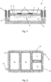
- Figure 1 shows a cross-section through part of a power electronics module 1 having a plurality of power converter semiconductor components 2. These components are bonded to a top surface of a substrate 3, e.g. by soldering or sintering.
- the bottom surface of the substrate is covered in an array of pin or fin heat transfer structures 4, formed e.g. by machining or 3D printing.
- the pin or fins increase the substrate surface area and cause turbulence in a coolant flow (discussed below).
- the substrate 3 is typically formed of a single layer of high thermal conductivity material, for example metal such as copper or aluminium, or metal matrix composite such as aluminium-graphite MMC. Avoiding the multi-layer construction of conventional substrates improves heat conduction away from the components 2, and reduces the number of potentially degradable interfaces.
- the top surface of the substrate may be coated with a ceramic or dielectric material coating 5 in the areas around the semiconductor components 2.
- the ceramic or dielectric may in turn have a thin metallisation coating 6 to facilitate electrical connection between components using bond wires 7 or planar interconnects.
- the metallisation may be etched to allow specific interconnections to be formed.
- the top surface of the substrate 3 is encased within a non-conductive protective cover or shell 8.
- the cover may contain electrical connections between the semiconductor components 2 and external parts of the module 1.
- the cover is impervious to the coolant and forms a fluid-tight seal to the substrate.
- the module 1 has a plate-like coolant housing 10 which forms a void 11 over the array of pins or fins 4 of the bottom surface of the substrate 3.
- Figure 2 shows a plan view of such a housing which forms a plurality of voids 11 for respective substrates 3 of plural modules 1, i.e. in Figure 2 a single unitary housing is shared by the modules.
- An inlet 12 guides a flow of a coolant into the voids, and an outlet 13 removes the coolant flow from the voids.
- the housing can be configured so that the coolant flows in series or in parallel through the voids from the inlet to the outlet.
- the order of flow through the voids can be optimised based on e.g.
- the housing can electrically isolate the modules from each other, as well as facilitating mounting into a converter structure, e.g. of an electric starter-generator of an aircraft engine.
- the housing allows modules to be swapped during service and may contain one or more modules depending on converter requirements.
- the cover 8 may have bolt holes 9 to facilitate mounting and/or other fastening formations for e.g. clips.
- the bolt holes 9 can also be used to join the cover to the coolant housing 10 via corresponding bolt holes 14 in the housing.
- Gaskets 15 may be provided at the cover/housing interface to form fluid-tight seals around the voids 11 and thereby prevent leakage of the coolant.
- the coolant is electrically insulating, and can be, for example, dry air, mineral oil, silicone oil, benzene, or fluorinated ketone such as Novec TM (available from 3M).
- the cover 8 and the housing 10 can be formed of electrical insulator (i.e. dielectric material).
- the gaskets 15, which may be formed of rubber, can also be used to electrically isolate the housing 10 from the cover 8 and thence from the substrate 3. Indeed, such an arrangement can allow the housing 10 to be formed of non-electrical insulator, although it may then be necessary to take other precautions such as using electrically insulating fasteners to join the cover to the housing.
- the power electronics module could be used in any power electronic circuit or system where power density is a concern.
- the exemplary embodiments of the invention set forth above are considered to be illustrative and not limiting. Various changes to the described embodiments may be made without departing from the spirit and scope of the invention.
Landscapes
- Engineering & Computer Science (AREA)
- Microelectronics & Electronic Packaging (AREA)
- Chemical & Material Sciences (AREA)
- Combustion & Propulsion (AREA)
- Mechanical Engineering (AREA)
- Aviation & Aerospace Engineering (AREA)
- Physics & Mathematics (AREA)
- Thermal Sciences (AREA)
- General Engineering & Computer Science (AREA)
- Power Engineering (AREA)
- Cooling Or The Like Of Semiconductors Or Solid State Devices (AREA)
- Cooling Or The Like Of Electrical Apparatus (AREA)
Abstract
Description
- The present invention relates to a power electronics module.
- Power electronic modules are typically used as the building blocks of power converters, such as inverters for the control of electric motors. For example, within an aircraft such modules may be used within a converter which powers an all-electric starter-generator. Power electronic modules may be used in a wide number of industries including transport where it may be used in hybrid electric systems for aero, marine and/or land based transport. They can also be used within power generation industries as well as civil and military infrastructure. The modules described herein are generally applicable to any industry that uses power electronics.
- Power electronic modules are typically mounted to a heat sink in order to facilitate heat transfer away from the semiconductor components of the modules.
- Conventionally, power electronic modules have a number of substrate layers between the semiconductor components and the outside environment. These layers provide mechanical support, electrical isolation, electrical connection, protection and thermal management of the components. Typically the heat flux generated from losses within the semiconductor is directed downwards, through the many layers, into a heat sink.
- For example, a substrate for a module may be formed with a ceramic layer (e.g. AlN) sandwiched between two metal layers (e.g. Cu metallization layers). The bottom metal layer can then be soldered to a metal-matrix composite (e.g. Al-SiC) baseplate, which in turn is connected to the heat sink.
- A problem arises, however, that the number of substrate layers within the module present a significant thermal resistance and therefore limit the power handling of the semiconductors or can cause unacceptable heat rises. Particularly problematic can be the thermal interface materials used to create thermal connections between layers. There can also be reliability issues due to degradation of these interfaces.
- It would be desirable to be able to reduce the number of substrate layers, thereby reducing resistance to heat flow, improving reliabilities, and potentially decreasing the overall weight of power electronic modules.
- Accordingly, in a first aspect, the present invention provides a power electronics module having:
- one or more power converter semiconductor components;
- a substrate having a first surface to which the one or more components are mounted, and having an opposing second surface from which project a plurality of heat transfer formations for enhancing heat transfer from the substrate; and
- a coolant housing which sealingly connects to the substrate to form a void over the heat transfer formations of the second surface, the coolant housing having an inlet for directing a flow of an electrically insulating coolant into the void and an outlet for removing the coolant flow from the void, whereby heat generated during operation of the one or more components is transferred into the coolant flow via the substrate.
- By extracting heat from the semiconductor components into the coolant flow via the metal substrate (and especially via the heat transfer formations), efficient and reliable cooling of the components can be achieved while reducing the number of substrate layers.
- In a second aspect, the present invention provides a plurality of power electronics modules according to the first aspect, each power electronics module having a respective substrate, a shared unitary coolant housing forming a plurality of respective voids over the heat transfer formations of the second surfaces of the substrates. The unitary coolant housing may be configured such that the coolant flows in series or in parallel between the voids from the inlet to the outlet.
- In a third aspect, the present invention provides an electric starter-generator for an aircraft engine, the starter-generator having the power electronics module of the first aspect or the power electronics modules of the second aspect.
- In a fourth aspect, the present invention provides an aircraft engine, such as a gas turbine engine, having the electric starter-generator of the third aspect.
- Optional features of the invention will now be set out. These are applicable singly or in any combination with any aspect of the invention.
- The substrate may be a single layer of material from the first surface to the second surface. By using a single layer rather than a multi-layer construction, resistance to heat flow can be reduced and interfacial degradation within the substrate avoided.
- The coolant housing may be formed of an electrical insulator. Additionally or alternatively, the coolant housing may be sealingly connected to the substrate via an electrically insulating gasket which electrically isolates the housing from the substrate.
- The power electronics module may further have a protective cover formed of an electrical insulator for the one or more components. For example, the protective cover may have electrical connectors extending from the outside of the cover to the one or more components. Such a protective cover can mediate the connection between the coolant housing and the substrate. For example, the protective cover may be sealingly connected to the substrate, and the coolant housing then sealingly connected to the cover.
- Typically, the substrate is formed of material having a thermal conductivity of at least 100 Wm-1K-1 and preferably of at least 200 Wm-1K-1. The material of the substrate may be a metal or metal matrix composite, such as copper, aluminium, or aluminium-graphite metal matrix composite.
- The heat transfer formations can be pins and/or fins. Preferably the heat transfer formations may be integral and homogeneously formed with the substrate. The formations may be manufactured by a material removal technique such as etching or mechanical machining of the substrate or by an additive technique such as powder bed or blown or wire deposition where material is applied to a pool of melted material formed on the second surface by a laser or other energy source. Where the heat transfer formations are made by additive manufacture their shape may be more complex and could include, for example, serpentine or wavy shapes plus hollow or perforated pins and/or fins, amongst others.
- The one or more components may be soldered or sintered to the first surface of the substrate.
- Areas of the first surface of the substrate surrounding the one or more components may have an electrically insulating coating. A metallisation coating may then be formed on the electrically insulating coating, e.g. to facilitate electrical connection between components using bond wires or planar interconnects.
- The coolant may be an isolating (i.e. dielectric) fluid, such as dry air, mineral oil, silicone oil, benzene, or fluorinated ketone.
- The coolant housing may be sealingly connected to the substrate around a perimeter of the void.
- A pumping unit may be provided for circulating the coolant. A heat exchanger may be provided for cooling the coolant removed through the outlet.
- Embodiments of the invention will now be described by way of example with reference to the accompanying drawings in which:
-
Figure 1 shows a cross-section through part of a power electronics module; and -
Figure 2 shows a plan view of a coolant housing for such a module. -
Figure 1 shows a cross-section through part of apower electronics module 1 having a plurality of powerconverter semiconductor components 2. These components are bonded to a top surface of asubstrate 3, e.g. by soldering or sintering. The bottom surface of the substrate is covered in an array of pin or finheat transfer structures 4, formed e.g. by machining or 3D printing. The pin or fins increase the substrate surface area and cause turbulence in a coolant flow (discussed below). - The
substrate 3 is typically formed of a single layer of high thermal conductivity material, for example metal such as copper or aluminium, or metal matrix composite such as aluminium-graphite MMC. Avoiding the multi-layer construction of conventional substrates improves heat conduction away from thecomponents 2, and reduces the number of potentially degradable interfaces. - The top surface of the substrate may be coated with a ceramic or
dielectric material coating 5 in the areas around thesemiconductor components 2. The ceramic or dielectric may in turn have athin metallisation coating 6 to facilitate electrical connection between components usingbond wires 7 or planar interconnects. The metallisation may be etched to allow specific interconnections to be formed. - The top surface of the
substrate 3 is encased within a non-conductive protective cover orshell 8. The cover may contain electrical connections between thesemiconductor components 2 and external parts of themodule 1. The cover is impervious to the coolant and forms a fluid-tight seal to the substrate. - To guide and contain the coolant, the
module 1 has a plate-like coolant housing 10 which forms a void 11 over the array of pins orfins 4 of the bottom surface of thesubstrate 3.Figure 2 shows a plan view of such a housing which forms a plurality ofvoids 11 forrespective substrates 3 ofplural modules 1, i.e. inFigure 2 a single unitary housing is shared by the modules. Aninlet 12 guides a flow of a coolant into the voids, and anoutlet 13 removes the coolant flow from the voids. The housing can be configured so that the coolant flows in series or in parallel through the voids from the inlet to the outlet. For example, the order of flow through the voids can be optimised based on e.g. the types ofcomponents 2 to be cooled. The housing can electrically isolate the modules from each other, as well as facilitating mounting into a converter structure, e.g. of an electric starter-generator of an aircraft engine. The housing allows modules to be swapped during service and may contain one or more modules depending on converter requirements. - The
cover 8 may havebolt holes 9 to facilitate mounting and/or other fastening formations for e.g. clips. The bolt holes 9 can also be used to join the cover to thecoolant housing 10 via corresponding bolt holes 14 in the housing.Gaskets 15 may be provided at the cover/housing interface to form fluid-tight seals around thevoids 11 and thereby prevent leakage of the coolant. - To provide electrical isolation, the coolant is electrically insulating, and can be, for example, dry air, mineral oil, silicone oil, benzene, or fluorinated ketone such as Novec™ (available from 3M). Moreover, the
cover 8 and thehousing 10 can be formed of electrical insulator (i.e. dielectric material). Thegaskets 15, which may be formed of rubber, can also be used to electrically isolate thehousing 10 from thecover 8 and thence from thesubstrate 3. Indeed, such an arrangement can allow thehousing 10 to be formed of non-electrical insulator, although it may then be necessary to take other precautions such as using electrically insulating fasteners to join the cover to the housing. - While the invention has been described in conjunction with the exemplary embodiments described above, many equivalent modifications and variations will be apparent to those skilled in the art when given this disclosure. For example, the power electronics module could be used in any power electronic circuit or system where power density is a concern. As well as aerospace, automotive, land and sea applications are also possible. Accordingly, the exemplary embodiments of the invention set forth above are considered to be illustrative and not limiting. Various changes to the described embodiments may be made without departing from the spirit and scope of the invention.
Claims (14)
- A power electronics module (41) having:one or more power converter semiconductor components (2);a substrate (3) having a first surface to which the one or more components (2) are mounted, and having an opposing second surface from which project a plurality of heat transfer formations (4) for enhancing heat transfer from the substrate; anda coolant housing (10) which defines with the substrate a void (11) over the heat transfer formations (4) of the second surface, the coolant housing (10) having an inlet (12) for directing a flow of an electrically insulating coolant into the void (11) and an outlet (13) for removing the coolant flow from the void (11), whereby heat generated during operation of the one or more components (2) is transferred into the coolant flow via the substrate; wherein the substrate is a single layer of material from the first surface to the second surface.
- A power electronics module according to claim 1, wherein the one or more components (2) are directly mounted to the first surface.
- A power electronics module according to claim 1 or 2, wherein the coolant housing (10) is formed of an electrical insulator.
- A power electronics module according to any one of the previous claims, wherein the coolant housing (10) is sealingly connected to the substrate via an electrically insulating gasket (15) which electrically isolates the housing (10) from the substrate.
- A power electronics module according to any one of the previous claims further having a protective cover (8) formed of an electrical insulator for the one or more components (2), the protective cover having electrical connectors extending from the outside of the cover to the one or more components (2).
- A power electronics module according to claim 5, wherein the protective cover mediates the connection between the coolant housing (10) and the substrate.
- A power electronics module according to any one of the previous claims, wherein the heat transfer formations (4) are pins and/or fins.
- A power electronics module according to any one of the previous claims, wherein the one or more components (2) are soldered or sintered to the first surface of the substrate.
- A power electronics module according to any one of the previous claims, wherein areas of the first surface of the substrate surrounding the one or more components (2) have an electrically insulating coating (5).
- A power electronics module according to any one of the previous claims, wherein the coolant is an isolating fluid.
- A power electronics module according to any one of the previous claims, wherein the coolant housing (10) is sealingly connected to the substrate around a perimeter of the void (11).
- A plurality of power electronics modules according to any one of the previous claim, each power electronics module having a respective substrate, a shared unitary coolant housing (10) forming a plurality of respective voids (11) over the heat transfer formations (4) of the second surfaces of the substrates.
- A power electronics module according to claim 12, wherein the unitary coolant housing (10) is configured such that the coolant flows in series between the voids (11) from the inlet to the outlet (13).
- An electric starter-generator for an aircraft engine, the starter-generator having the power electronics module according to any one of claims 1 to 11 or a plurality of power electronics modules according to claim 12 or 13.
Applications Claiming Priority (1)
| Application Number | Priority Date | Filing Date | Title |
|---|---|---|---|
| GB201606708 | 2016-04-18 |
Publications (3)
| Publication Number | Publication Date |
|---|---|
| EP3236725A1 true EP3236725A1 (en) | 2017-10-25 |
| EP3236725B1 EP3236725B1 (en) | 2020-02-05 |
| EP3236725B8 EP3236725B8 (en) | 2020-03-11 |
Family
ID=58398100
Family Applications (1)
| Application Number | Title | Priority Date | Filing Date |
|---|---|---|---|
| EP17162074.3A Active EP3236725B8 (en) | 2016-04-18 | 2017-03-21 | Power electronics module |
Country Status (2)
| Country | Link |
|---|---|
| US (1) | US10049963B2 (en) |
| EP (1) | EP3236725B8 (en) |
Cited By (3)
| Publication number | Priority date | Publication date | Assignee | Title |
|---|---|---|---|---|
| CN110968630A (en) * | 2019-11-28 | 2020-04-07 | 广州供电局有限公司 | Network command issuing method and device, computer equipment and storage medium |
| EP3845749A1 (en) * | 2020-01-06 | 2021-07-07 | Hamilton Sundstrand Corporation | Starter/generator arrangements for gas turbine engines |
| DE102020214397A1 (en) | 2020-11-17 | 2022-05-19 | Volkswagen Aktiengesellschaft | Process for manufacturing a unit with an electronic module |
Families Citing this family (7)
| Publication number | Priority date | Publication date | Assignee | Title |
|---|---|---|---|---|
| KR102756060B1 (en) * | 2018-11-14 | 2025-01-20 | 엘지이노텍 주식회사 | Electronic component assembly |
| US11611122B2 (en) | 2020-07-06 | 2023-03-21 | Dana Automotive Systems Group, Llc | Electric vehicle battery coolant heater assembly with electrical connection through gasket |
| CN112750600B (en) * | 2020-12-29 | 2022-05-17 | 华进半导体封装先导技术研发中心有限公司 | A kind of adjustable inductor based on microfluidic channel and its manufacturing method |
| US20250122842A1 (en) * | 2022-06-22 | 2025-04-17 | General Electric Company | Gearbox assembly with lubricant extraction volume ratio |
| US20240203809A1 (en) * | 2022-12-20 | 2024-06-20 | Eagle Technology. Llc | Electronic device including rigid dielectric lid and overlaying thermoset polymer layer and related methods |
| KR20240105891A (en) * | 2022-12-29 | 2024-07-08 | 현대자동차주식회사 | Power module |
| FR3157054A1 (en) * | 2023-12-14 | 2025-06-20 | Safran Electrical & Power | POWER ELECTRONIC MODULE |
Citations (8)
| Publication number | Priority date | Publication date | Assignee | Title |
|---|---|---|---|---|
| US20010014029A1 (en) * | 2000-02-16 | 2001-08-16 | Osamu Suzuki | Power inverter |
| US20080237847A1 (en) * | 2007-03-30 | 2008-10-02 | Nichicon Corporation | Power semiconductor module, and power semiconductor device having the module mounted therein |
| JP2009206191A (en) * | 2008-02-26 | 2009-09-10 | Sumitomo Electric Ind Ltd | Power module |
| US20100232112A1 (en) * | 2009-03-12 | 2010-09-16 | Aisin Aw Co., Ltd. | Semiconductor module |
| WO2013118809A1 (en) * | 2012-02-09 | 2013-08-15 | 日産自動車株式会社 | Semiconductor cooling device |
| US20140168897A1 (en) * | 2012-12-13 | 2014-06-19 | Vacon Oyj | Power electronics device and its cooling arrangement |
| US20140347818A1 (en) * | 2013-05-24 | 2014-11-27 | Infineon Technologies Ag | Power Semiconductor Module with Liquid Cooling |
| US20140376184A1 (en) * | 2012-04-16 | 2014-12-25 | Fuji Electric Co. Ltd. | Semiconductor device and cooler thereof |
Family Cites Families (4)
| Publication number | Priority date | Publication date | Assignee | Title |
|---|---|---|---|---|
| US6973801B1 (en) * | 2004-12-09 | 2005-12-13 | International Business Machines Corporation | Cooling system and method employing a closed loop coolant path and micro-scaled cooling structure within an electronics subsystem of an electronics rack |
| US8297342B2 (en) * | 2009-06-29 | 2012-10-30 | International Business Machines Corporation | Heat sink assembly |
| US10531594B2 (en) * | 2010-07-28 | 2020-01-07 | Wieland Microcool, Llc | Method of producing a liquid cooled coldplate |
| WO2015025582A1 (en) | 2013-08-23 | 2015-02-26 | 日立オートモティブシステムズ株式会社 | Power conversion device |
-
2017
- 2017-03-21 EP EP17162074.3A patent/EP3236725B8/en active Active
- 2017-03-21 US US15/465,234 patent/US10049963B2/en active Active
Patent Citations (8)
| Publication number | Priority date | Publication date | Assignee | Title |
|---|---|---|---|---|
| US20010014029A1 (en) * | 2000-02-16 | 2001-08-16 | Osamu Suzuki | Power inverter |
| US20080237847A1 (en) * | 2007-03-30 | 2008-10-02 | Nichicon Corporation | Power semiconductor module, and power semiconductor device having the module mounted therein |
| JP2009206191A (en) * | 2008-02-26 | 2009-09-10 | Sumitomo Electric Ind Ltd | Power module |
| US20100232112A1 (en) * | 2009-03-12 | 2010-09-16 | Aisin Aw Co., Ltd. | Semiconductor module |
| WO2013118809A1 (en) * | 2012-02-09 | 2013-08-15 | 日産自動車株式会社 | Semiconductor cooling device |
| US20140376184A1 (en) * | 2012-04-16 | 2014-12-25 | Fuji Electric Co. Ltd. | Semiconductor device and cooler thereof |
| US20140168897A1 (en) * | 2012-12-13 | 2014-06-19 | Vacon Oyj | Power electronics device and its cooling arrangement |
| US20140347818A1 (en) * | 2013-05-24 | 2014-11-27 | Infineon Technologies Ag | Power Semiconductor Module with Liquid Cooling |
Cited By (4)
| Publication number | Priority date | Publication date | Assignee | Title |
|---|---|---|---|---|
| CN110968630A (en) * | 2019-11-28 | 2020-04-07 | 广州供电局有限公司 | Network command issuing method and device, computer equipment and storage medium |
| EP3845749A1 (en) * | 2020-01-06 | 2021-07-07 | Hamilton Sundstrand Corporation | Starter/generator arrangements for gas turbine engines |
| US11428168B2 (en) | 2020-01-06 | 2022-08-30 | Hamilton Sundstrand Corporation | Starter/generator arrangements for gas turbine engines |
| DE102020214397A1 (en) | 2020-11-17 | 2022-05-19 | Volkswagen Aktiengesellschaft | Process for manufacturing a unit with an electronic module |
Also Published As
| Publication number | Publication date |
|---|---|
| US10049963B2 (en) | 2018-08-14 |
| EP3236725B1 (en) | 2020-02-05 |
| US20170301609A1 (en) | 2017-10-19 |
| EP3236725B8 (en) | 2020-03-11 |
Similar Documents
| Publication | Publication Date | Title |
|---|---|---|
| EP3236725B1 (en) | Power electronics module | |
| CN112930078B (en) | Cold plate assembly for electronic components | |
| US10492344B2 (en) | Power module | |
| US8804339B2 (en) | Power electronics assemblies, insulated metal substrate assemblies, and vehicles incorporating the same | |
| US8649179B2 (en) | Circuit assemblies including thermoelectric modules | |
| US7492594B2 (en) | Electronic circuit modules cooling | |
| US8520389B2 (en) | Power semiconductor module for wide temperature applications | |
| US9263365B2 (en) | Electronic component and electronic component cooling method | |
| US20110030754A1 (en) | Thermoelectric modules and related methods | |
| CN110325018B (en) | Avionics cooling module | |
| CN112335040A (en) | Cooling assembly for electrical components, rectifier with cooling assembly and aerial vehicle with rectifier | |
| CN113782504A (en) | Simplified packaging structure of power module of integrated radiator and manufacturing method | |
| US20240015881A1 (en) | Printed circuit board (pcb) cooling | |
| JP2008311550A (en) | Power semiconductor module | |
| US12322604B2 (en) | Method for manufacturing an electronic power module using polymer preforms | |
| GB2565071A (en) | Semiconductor module | |
| US11006513B1 (en) | Electronic assembly having sectional thermal management | |
| JP7193395B2 (en) | power semiconductor equipment | |
| US12255121B2 (en) | Power semiconductor cooling assembly | |
| CN114730752B (en) | Conductive metal frame for power electronic module and related manufacturing method | |
| US20230420901A1 (en) | Electronic connection assembly | |
| DK177415B1 (en) | Power module cooling | |
| CN120301149A (en) | A power module, a power converter and a heat sink | |
| CN117440653A (en) | Power electronic modules |
Legal Events
| Date | Code | Title | Description |
|---|---|---|---|
| PUAI | Public reference made under article 153(3) epc to a published international application that has entered the european phase |
Free format text: ORIGINAL CODE: 0009012 |
|
| STAA | Information on the status of an ep patent application or granted ep patent |
Free format text: STATUS: THE APPLICATION HAS BEEN PUBLISHED |
|
| AK | Designated contracting states |
Kind code of ref document: A1 Designated state(s): AL AT BE BG CH CY CZ DE DK EE ES FI FR GB GR HR HU IE IS IT LI LT LU LV MC MK MT NL NO PL PT RO RS SE SI SK SM TR |
|
| AX | Request for extension of the european patent |
Extension state: BA ME |
|
| STAA | Information on the status of an ep patent application or granted ep patent |
Free format text: STATUS: REQUEST FOR EXAMINATION WAS MADE |
|
| 17P | Request for examination filed |
Effective date: 20180425 |
|
| RBV | Designated contracting states (corrected) |
Designated state(s): AL AT BE BG CH CY CZ DE DK EE ES FI FR GB GR HR HU IE IS IT LI LT LU LV MC MK MT NL NO PL PT RO RS SE SI SK SM TR |
|
| STAA | Information on the status of an ep patent application or granted ep patent |
Free format text: STATUS: EXAMINATION IS IN PROGRESS |
|
| 17Q | First examination report despatched |
Effective date: 20190402 |
|
| GRAP | Despatch of communication of intention to grant a patent |
Free format text: ORIGINAL CODE: EPIDOSNIGR1 |
|
| STAA | Information on the status of an ep patent application or granted ep patent |
Free format text: STATUS: GRANT OF PATENT IS INTENDED |
|
| INTG | Intention to grant announced |
Effective date: 20191016 |
|
| GRAS | Grant fee paid |
Free format text: ORIGINAL CODE: EPIDOSNIGR3 |
|
| GRAA | (expected) grant |
Free format text: ORIGINAL CODE: 0009210 |
|
| STAA | Information on the status of an ep patent application or granted ep patent |
Free format text: STATUS: THE PATENT HAS BEEN GRANTED |
|
| AK | Designated contracting states |
Kind code of ref document: B1 Designated state(s): AL AT BE BG CH CY CZ DE DK EE ES FI FR GB GR HR HU IE IS IT LI LT LU LV MC MK MT NL NO PL PT RO RS SE SI SK SM TR |
|
| REG | Reference to a national code |
Ref country code: GB Ref legal event code: FG4D |
|
| REG | Reference to a national code |
Ref country code: CH Ref legal event code: PK Free format text: BERICHTIGUNG B8 |
|
| REG | Reference to a national code |
Ref country code: AT Ref legal event code: REF Ref document number: 1230858 Country of ref document: AT Kind code of ref document: T Effective date: 20200215 |
|
| REG | Reference to a national code |
Ref country code: DE Ref legal event code: R096 Ref document number: 602017011322 Country of ref document: DE |
|
| RAP2 | Party data changed (patent owner data changed or rights of a patent transferred) |
Owner name: ROLLS-ROYCE PLC |
|
| REG | Reference to a national code |
Ref country code: IE Ref legal event code: FG4D |
|
| REG | Reference to a national code |
Ref country code: CH Ref legal event code: EP |
|
| REG | Reference to a national code |
Ref country code: NL Ref legal event code: MP Effective date: 20200205 |
|
| PG25 | Lapsed in a contracting state [announced via postgrant information from national office to epo] |
Ref country code: RS Free format text: LAPSE BECAUSE OF FAILURE TO SUBMIT A TRANSLATION OF THE DESCRIPTION OR TO PAY THE FEE WITHIN THE PRESCRIBED TIME-LIMIT Effective date: 20200205 Ref country code: FI Free format text: LAPSE BECAUSE OF FAILURE TO SUBMIT A TRANSLATION OF THE DESCRIPTION OR TO PAY THE FEE WITHIN THE PRESCRIBED TIME-LIMIT Effective date: 20200205 Ref country code: NO Free format text: LAPSE BECAUSE OF FAILURE TO SUBMIT A TRANSLATION OF THE DESCRIPTION OR TO PAY THE FEE WITHIN THE PRESCRIBED TIME-LIMIT Effective date: 20200505 Ref country code: PT Free format text: LAPSE BECAUSE OF FAILURE TO SUBMIT A TRANSLATION OF THE DESCRIPTION OR TO PAY THE FEE WITHIN THE PRESCRIBED TIME-LIMIT Effective date: 20200628 |
|
| REG | Reference to a national code |
Ref country code: LT Ref legal event code: MG4D |
|
| PG25 | Lapsed in a contracting state [announced via postgrant information from national office to epo] |
Ref country code: LV Free format text: LAPSE BECAUSE OF FAILURE TO SUBMIT A TRANSLATION OF THE DESCRIPTION OR TO PAY THE FEE WITHIN THE PRESCRIBED TIME-LIMIT Effective date: 20200205 Ref country code: SE Free format text: LAPSE BECAUSE OF FAILURE TO SUBMIT A TRANSLATION OF THE DESCRIPTION OR TO PAY THE FEE WITHIN THE PRESCRIBED TIME-LIMIT Effective date: 20200205 Ref country code: BG Free format text: LAPSE BECAUSE OF FAILURE TO SUBMIT A TRANSLATION OF THE DESCRIPTION OR TO PAY THE FEE WITHIN THE PRESCRIBED TIME-LIMIT Effective date: 20200505 Ref country code: IS Free format text: LAPSE BECAUSE OF FAILURE TO SUBMIT A TRANSLATION OF THE DESCRIPTION OR TO PAY THE FEE WITHIN THE PRESCRIBED TIME-LIMIT Effective date: 20200605 Ref country code: HR Free format text: LAPSE BECAUSE OF FAILURE TO SUBMIT A TRANSLATION OF THE DESCRIPTION OR TO PAY THE FEE WITHIN THE PRESCRIBED TIME-LIMIT Effective date: 20200205 Ref country code: GR Free format text: LAPSE BECAUSE OF FAILURE TO SUBMIT A TRANSLATION OF THE DESCRIPTION OR TO PAY THE FEE WITHIN THE PRESCRIBED TIME-LIMIT Effective date: 20200506 |
|
| PG25 | Lapsed in a contracting state [announced via postgrant information from national office to epo] |
Ref country code: NL Free format text: LAPSE BECAUSE OF FAILURE TO SUBMIT A TRANSLATION OF THE DESCRIPTION OR TO PAY THE FEE WITHIN THE PRESCRIBED TIME-LIMIT Effective date: 20200205 |
|
| PG25 | Lapsed in a contracting state [announced via postgrant information from national office to epo] |
Ref country code: SK Free format text: LAPSE BECAUSE OF FAILURE TO SUBMIT A TRANSLATION OF THE DESCRIPTION OR TO PAY THE FEE WITHIN THE PRESCRIBED TIME-LIMIT Effective date: 20200205 Ref country code: SM Free format text: LAPSE BECAUSE OF FAILURE TO SUBMIT A TRANSLATION OF THE DESCRIPTION OR TO PAY THE FEE WITHIN THE PRESCRIBED TIME-LIMIT Effective date: 20200205 Ref country code: EE Free format text: LAPSE BECAUSE OF FAILURE TO SUBMIT A TRANSLATION OF THE DESCRIPTION OR TO PAY THE FEE WITHIN THE PRESCRIBED TIME-LIMIT Effective date: 20200205 Ref country code: DK Free format text: LAPSE BECAUSE OF FAILURE TO SUBMIT A TRANSLATION OF THE DESCRIPTION OR TO PAY THE FEE WITHIN THE PRESCRIBED TIME-LIMIT Effective date: 20200205 Ref country code: ES Free format text: LAPSE BECAUSE OF FAILURE TO SUBMIT A TRANSLATION OF THE DESCRIPTION OR TO PAY THE FEE WITHIN THE PRESCRIBED TIME-LIMIT Effective date: 20200205 Ref country code: CZ Free format text: LAPSE BECAUSE OF FAILURE TO SUBMIT A TRANSLATION OF THE DESCRIPTION OR TO PAY THE FEE WITHIN THE PRESCRIBED TIME-LIMIT Effective date: 20200205 Ref country code: RO Free format text: LAPSE BECAUSE OF FAILURE TO SUBMIT A TRANSLATION OF THE DESCRIPTION OR TO PAY THE FEE WITHIN THE PRESCRIBED TIME-LIMIT Effective date: 20200205 Ref country code: LT Free format text: LAPSE BECAUSE OF FAILURE TO SUBMIT A TRANSLATION OF THE DESCRIPTION OR TO PAY THE FEE WITHIN THE PRESCRIBED TIME-LIMIT Effective date: 20200205 |
|
| REG | Reference to a national code |
Ref country code: CH Ref legal event code: PL |
|
| REG | Reference to a national code |
Ref country code: DE Ref legal event code: R097 Ref document number: 602017011322 Country of ref document: DE |
|
| REG | Reference to a national code |
Ref country code: AT Ref legal event code: MK05 Ref document number: 1230858 Country of ref document: AT Kind code of ref document: T Effective date: 20200205 |
|
| PG25 | Lapsed in a contracting state [announced via postgrant information from national office to epo] |
Ref country code: MC Free format text: LAPSE BECAUSE OF FAILURE TO SUBMIT A TRANSLATION OF THE DESCRIPTION OR TO PAY THE FEE WITHIN THE PRESCRIBED TIME-LIMIT Effective date: 20200205 |
|
| PLBE | No opposition filed within time limit |
Free format text: ORIGINAL CODE: 0009261 |
|
| STAA | Information on the status of an ep patent application or granted ep patent |
Free format text: STATUS: NO OPPOSITION FILED WITHIN TIME LIMIT |
|
| REG | Reference to a national code |
Ref country code: BE Ref legal event code: MM Effective date: 20200331 |
|
| PG25 | Lapsed in a contracting state [announced via postgrant information from national office to epo] |
Ref country code: LU Free format text: LAPSE BECAUSE OF NON-PAYMENT OF DUE FEES Effective date: 20200321 |
|
| 26N | No opposition filed |
Effective date: 20201106 |
|
| PG25 | Lapsed in a contracting state [announced via postgrant information from national office to epo] |
Ref country code: LI Free format text: LAPSE BECAUSE OF NON-PAYMENT OF DUE FEES Effective date: 20200331 Ref country code: IE Free format text: LAPSE BECAUSE OF NON-PAYMENT OF DUE FEES Effective date: 20200321 Ref country code: AT Free format text: LAPSE BECAUSE OF FAILURE TO SUBMIT A TRANSLATION OF THE DESCRIPTION OR TO PAY THE FEE WITHIN THE PRESCRIBED TIME-LIMIT Effective date: 20200205 Ref country code: IT Free format text: LAPSE BECAUSE OF FAILURE TO SUBMIT A TRANSLATION OF THE DESCRIPTION OR TO PAY THE FEE WITHIN THE PRESCRIBED TIME-LIMIT Effective date: 20200205 Ref country code: CH Free format text: LAPSE BECAUSE OF NON-PAYMENT OF DUE FEES Effective date: 20200331 |
|
| PG25 | Lapsed in a contracting state [announced via postgrant information from national office to epo] |
Ref country code: BE Free format text: LAPSE BECAUSE OF NON-PAYMENT OF DUE FEES Effective date: 20200331 Ref country code: SI Free format text: LAPSE BECAUSE OF FAILURE TO SUBMIT A TRANSLATION OF THE DESCRIPTION OR TO PAY THE FEE WITHIN THE PRESCRIBED TIME-LIMIT Effective date: 20200205 Ref country code: PL Free format text: LAPSE BECAUSE OF FAILURE TO SUBMIT A TRANSLATION OF THE DESCRIPTION OR TO PAY THE FEE WITHIN THE PRESCRIBED TIME-LIMIT Effective date: 20200205 |
|
| PG25 | Lapsed in a contracting state [announced via postgrant information from national office to epo] |
Ref country code: TR Free format text: LAPSE BECAUSE OF FAILURE TO SUBMIT A TRANSLATION OF THE DESCRIPTION OR TO PAY THE FEE WITHIN THE PRESCRIBED TIME-LIMIT Effective date: 20200205 Ref country code: MT Free format text: LAPSE BECAUSE OF FAILURE TO SUBMIT A TRANSLATION OF THE DESCRIPTION OR TO PAY THE FEE WITHIN THE PRESCRIBED TIME-LIMIT Effective date: 20200205 Ref country code: CY Free format text: LAPSE BECAUSE OF FAILURE TO SUBMIT A TRANSLATION OF THE DESCRIPTION OR TO PAY THE FEE WITHIN THE PRESCRIBED TIME-LIMIT Effective date: 20200205 |
|
| PG25 | Lapsed in a contracting state [announced via postgrant information from national office to epo] |
Ref country code: MK Free format text: LAPSE BECAUSE OF FAILURE TO SUBMIT A TRANSLATION OF THE DESCRIPTION OR TO PAY THE FEE WITHIN THE PRESCRIBED TIME-LIMIT Effective date: 20200205 Ref country code: AL Free format text: LAPSE BECAUSE OF FAILURE TO SUBMIT A TRANSLATION OF THE DESCRIPTION OR TO PAY THE FEE WITHIN THE PRESCRIBED TIME-LIMIT Effective date: 20200205 |
|
| P01 | Opt-out of the competence of the unified patent court (upc) registered |
Effective date: 20230528 |
|
| PGFP | Annual fee paid to national office [announced via postgrant information from national office to epo] |
Ref country code: GB Payment date: 20260323 Year of fee payment: 10 |
|
| PGFP | Annual fee paid to national office [announced via postgrant information from national office to epo] |
Ref country code: DE Payment date: 20260320 Year of fee payment: 10 |
|
| PGFP | Annual fee paid to national office [announced via postgrant information from national office to epo] |
Ref country code: FR Payment date: 20260323 Year of fee payment: 10 |