EP3236591B1 - Cellular network with a linear cell topology, node and method therefor - Google Patents
Cellular network with a linear cell topology, node and method therefor Download PDFInfo
- Publication number
- EP3236591B1 EP3236591B1 EP16166025.3A EP16166025A EP3236591B1 EP 3236591 B1 EP3236591 B1 EP 3236591B1 EP 16166025 A EP16166025 A EP 16166025A EP 3236591 B1 EP3236591 B1 EP 3236591B1
- Authority
- EP
- European Patent Office
- Prior art keywords
- node
- channel resource
- antenna
- channel
- user terminal
- Prior art date
- Legal status (The legal status is an assumption and is not a legal conclusion. Google has not performed a legal analysis and makes no representation as to the accuracy of the status listed.)
- Active
Links
- 230000001413 cellular effect Effects 0.000 title claims description 26
- 238000000034 method Methods 0.000 title claims description 9
- 238000004891 communication Methods 0.000 claims description 41
- 230000005540 biological transmission Effects 0.000 description 3
- 230000002452 interceptive effect Effects 0.000 description 3
- 230000003044 adaptive effect Effects 0.000 description 2
- 238000013459 approach Methods 0.000 description 1
- 238000009434 installation Methods 0.000 description 1
- 238000012986 modification Methods 0.000 description 1
- 230000004048 modification Effects 0.000 description 1
Images


Classifications
-
- H—ELECTRICITY
- H04—ELECTRIC COMMUNICATION TECHNIQUE
- H04B—TRANSMISSION
- H04B7/00—Radio transmission systems, i.e. using radiation field
- H04B7/02—Diversity systems; Multi-antenna system, i.e. transmission or reception using multiple antennas
- H04B7/04—Diversity systems; Multi-antenna system, i.e. transmission or reception using multiple antennas using two or more spaced independent antennas
- H04B7/0491—Diversity systems; Multi-antenna system, i.e. transmission or reception using multiple antennas using two or more spaced independent antennas using two or more sectors, i.e. sector diversity
-
- H—ELECTRICITY
- H04—ELECTRIC COMMUNICATION TECHNIQUE
- H04B—TRANSMISSION
- H04B7/00—Radio transmission systems, i.e. using radiation field
- H04B7/02—Diversity systems; Multi-antenna system, i.e. transmission or reception using multiple antennas
- H04B7/04—Diversity systems; Multi-antenna system, i.e. transmission or reception using multiple antennas using two or more spaced independent antennas
- H04B7/0408—Diversity systems; Multi-antenna system, i.e. transmission or reception using multiple antennas using two or more spaced independent antennas using two or more beams, i.e. beam diversity
-
- H—ELECTRICITY
- H04—ELECTRIC COMMUNICATION TECHNIQUE
- H04W—WIRELESS COMMUNICATION NETWORKS
- H04W16/00—Network planning, e.g. coverage or traffic planning tools; Network deployment, e.g. resource partitioning or cells structures
- H04W16/24—Cell structures
- H04W16/30—Special cell shapes, e.g. doughnuts or ring cells
-
- H—ELECTRICITY
- H04—ELECTRIC COMMUNICATION TECHNIQUE
- H04W—WIRELESS COMMUNICATION NETWORKS
- H04W36/00—Hand-off or reselection arrangements
- H04W36/06—Reselecting a communication resource in the serving access point
-
- H—ELECTRICITY
- H04—ELECTRIC COMMUNICATION TECHNIQUE
- H04W—WIRELESS COMMUNICATION NETWORKS
- H04W36/00—Hand-off or reselection arrangements
- H04W36/24—Reselection being triggered by specific parameters
- H04W36/32—Reselection being triggered by specific parameters by location or mobility data, e.g. speed data
- H04W36/326—Reselection being triggered by specific parameters by location or mobility data, e.g. speed data by proximity to another entity
-
- H—ELECTRICITY
- H04—ELECTRIC COMMUNICATION TECHNIQUE
- H04W—WIRELESS COMMUNICATION NETWORKS
- H04W52/00—Power management, e.g. TPC [Transmission Power Control], power saving or power classes
- H04W52/04—TPC
- H04W52/06—TPC algorithms
- H04W52/14—Separate analysis of uplink or downlink
- H04W52/143—Downlink power control
-
- H—ELECTRICITY
- H04—ELECTRIC COMMUNICATION TECHNIQUE
- H04W—WIRELESS COMMUNICATION NETWORKS
- H04W52/00—Power management, e.g. TPC [Transmission Power Control], power saving or power classes
- H04W52/04—TPC
- H04W52/30—TPC using constraints in the total amount of available transmission power
- H04W52/34—TPC management, i.e. sharing limited amount of power among users or channels or data types, e.g. cell loading
- H04W52/346—TPC management, i.e. sharing limited amount of power among users or channels or data types, e.g. cell loading distributing total power among users or channels
-
- H—ELECTRICITY
- H04—ELECTRIC COMMUNICATION TECHNIQUE
- H04W—WIRELESS COMMUNICATION NETWORKS
- H04W72/00—Local resource management
- H04W72/04—Wireless resource allocation
- H04W72/044—Wireless resource allocation based on the type of the allocated resource
- H04W72/046—Wireless resource allocation based on the type of the allocated resource the resource being in the space domain, e.g. beams
-
- H—ELECTRICITY
- H04—ELECTRIC COMMUNICATION TECHNIQUE
- H04W—WIRELESS COMMUNICATION NETWORKS
- H04W84/00—Network topologies
- H04W84/005—Moving wireless networks
-
- H—ELECTRICITY
- H04—ELECTRIC COMMUNICATION TECHNIQUE
- H04W—WIRELESS COMMUNICATION NETWORKS
- H04W48/00—Access restriction; Network selection; Access point selection
- H04W48/08—Access restriction or access information delivery, e.g. discovery data delivery
- H04W48/10—Access restriction or access information delivery, e.g. discovery data delivery using broadcasted information
Definitions
- the present invention relates to a node for a cellular network with a linear cell topology for wirelessly communicating with user terminals.
- the invention further relates to a cellular network comprising a plurality of nodes and a method for communicating between a user terminal and a node.
- a cellular network comprises a plurality of radio transceivers or "nodes", through which users can gain access to the network by means of user terminals.
- a node is referred to as “eNB” (evolved Node B) and according to the GSM standard as “BTS” (Base Transceiver Station).
- eNB evolved Node B
- BTS Base Transceiver Station
- Each node comprises an antenna and defines a cell, which is delimited by the coverage area of the antenna. If a user terminal is within the coverage area of a node, it can wirelessly communicate with the node by sending and receiving data to and from the node.
- frequency reuse schemes are employed, one type of which will be described in the following for the case of a one-dimensional cellular network.
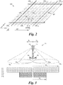
- Fig. 1 shows a conventional cellular network 1 with a one-dimensional ("linear") cell topology.
- nodes 2 communicate data 3 with user terminals 4, which only travel in one direction d L or the corresponding opposite direction d R , e.g., by riding on a train 5 on a railway track 6, driving by car on a highway or in a tunnel, et cet.
- the communication between the node 2 and the user terminal 4 is conducted by communication standards known in the state of the art, such as 3GPP LTE/LTE-A, IEEE WiMAX 802.17e, GSM, or GSM-R.
- the communication channel CH of a node 2 is divided in frequency f and/or time t into multiple channel resources CR 1 , CR 2 , ... generally CR i , as can be seen in Fig. 2 , which will be described in detail later.
- each node 2 has an omnidirectional antenna 7 mounted on a support 8 and controlled by a transceiver 9.
- Omnidirectional antennas communicate data 3 in both directions d L , d R of the node 2, i.e., it does not matter if a user terminal 4 is located to the left or to the right of a node 2 to establish communication.
- Each antenna 7 thus exhibits a coverage area 10 1 with a range r. Interference occurs when neighbouring nodes 2 use the same channel resource CR i .
- a node 2 uses its first three channel resources CR 1 , CR 2 , CR 3 to communicate data 3 at a high power level P 1 over a far coverage area 10 1 with range r, while it uses its last three communication resources CR 4 , CR 5 , CR 6 to communicate data 3 at a low power level P 2 over a near coverage area 10 2 , e.g., with a range r/2.
- data 3 is communicated in one (or more) of the high power level channel resources CR 1 , CR 2 , CR 3 .
- data 3 is communicated in one (or more) of the low power level channel resources CR 4 , CR 5 , CR 6 .
- the distance of a user terminal 4 can, for example, be measured by means of the received signal strength indication (RSSI) in the node 2 and/or the user terminal 4.
- RSSI received signal strength indication
- the two neighbouring nodes 2 on either side of the node 2 described before use a reversed scheme for the power levels P 1 , P 2 of the channel resources CR i , i.e., a low power level P 2 for the first three communication channels CR 1 , CR 2 , CR 3 , and a high power level P 1 for the last three communication channels CR 4 , CR 5 , CR 6 .
- the one-dimensional network 1 is then constructed by alternatingly using the described nodes 2.
- a user terminal 4 near the edge of a cell of a node 2 will communicate data 3 in a channel resource CR i at a high power level P 1 while the neighbouring node 2 will use only a lower power level P 2 for this specific channel resource CR i . Interference from neighbouring nodes 2 is therefore reduced, while the same channel resources CR i can be "reused" by neighbouring nodes 2 to a certain extent.
- the described one-dimensional cellular network 1 has the drawback that the amount of data 3 that can be communicated by a node 2 is limited. Furthermore, the interference experienced by user terminals 4 leaves room for improvement.
- WO 2011/100520 which lies in the field of cellular networks in which nodes cover extended geographical areas in two dimensions, shows cells that have multiple antennas that can employ different transmit powers but cover the same geographical areas.
- US 2016/0037550 A1 shows that for a soft frequency reuse different power levels can be employed for different communication resources. For each power level a separate scheduler is employed.
- a plurality of antenna sites 1 and 2 connected to a controller 30 can provide a cell 10.
- each of the antenna sites 1 and 2 provides a directional antenna providing beams 6 and 7.
- the directional beams 6 and 7 can overlap each other.
- An appropriate transmission scheme can be used to enable the two antenna site transmission diversity and reception or transmission of two transport blocks.
- the communications can take place on a single carrier, for example on a frequency resource.
- the invention provides for a node of the aforementioned type, wherein the node is configured to communicate data in at least a first and a second channel resource of a communication channel, which are separated in at least one of frequency and time, and wherein the node is further configured to employ different power levels for different channel resources, which is distinguished in that:
- the amount of communicated data can be doubled. This can be used to double the number of user terminals a node can host in its coverage area.
- the node Even though its throughput or hosting capacity is twice as high, the node still appears as a state of the art node to a user terminal. This is achieved by broadcasting the same cell-ID over both antennas, which leads the user terminals to belief that a conventional node is used. Thus, there is no need to exchange or re-program user terminals to be compatible with the new node of the network, which significantly simplifies implementation.
- the node is further configured to employ different power levels for a same channel resource over said first and second antenna.
- This allows the node not only to communicate twice the amount of data, but also to use different power level schemes for different directions.
- the usage of different power level schemes in different directions can be used to adapt the node to neighbouring nodes and/or to employ completely new reuse schemes between neighbouring nodes.
- further energy or power savings can be achieved since fewer high power levels can be employed, e.g., if there is only one user terminal close to the edge of the cell, the high power level does not have to be used for both directions.
- using lower power levels for some channel resources leaves more power for the other channel resources.
- the node is configured to communicate data
- the node employs a "Z-shaped" power level scheme, which leads to reduced interference for user terminals near the node:
- the second interfering node For a user terminal at a distance of, e.g., half of the maximum cell range r, i.e., 0,5 r to the node, the second interfering node is now at a greater distance of 3,5 r to the user terminal, while with a reuse scheme according to the state of the art the second interfering node is at a distance of only 2,5 r.
- nodes of the same type can be employed all in the same way one after the other, which greatly simplifies network planning, production, and installation.
- the node is configured to communicate data in a third channel resource over the first and the second antenna, wherein the node is further configured to communicate same data over the first and the second antenna in the third channel resource.
- the third channel resource in which data is communicated in parallel over both antennas, an intra-cell "switching" for a user terminal passing from one directional antenna to the other directional antenna of the same node can be greatly facilitated.
- the position of a user terminal cannot be reliably determined as to whether it is left or right of the node.
- the node may encounter problems in correctly allocating and attributing communications in same channel resources on either sides of the node to different user terminals.
- dedicated third channel resources with same data on either antenna of the node for very close user terminals, this allows for an undisturbed communication with user terminals passing through the close area of the node.
- the node is configured to communicate data in the third channel resource at a power level that is lower than the power levels of the first and second channel resources. Since the third channel resources are used only for user terminals close to the node, the power level of the third channel resources can be reduced as well. Thus, interferences are reduced for user terminals communicating in the same channel resource with a different node.
- the invention envisages two alternative embodiments for allocating the third channel resource.
- the node is configured to use a specific one of all channel resources of the communication channel for the third channel resource on both antennas.
- the node thus uses a predetermined channel resource, e.g., the lowest frequency and/or time slots, for the third channel resource. Neighbouring nodes then always know, which channel resource is not used for communication with user terminals at a high power level, and can thus themselves proceed to use this channel resource for communication with user terminals in their own cell at a high power level.
- the node is configured to reserve specific channel resources of all channel resources of the communication channel on both antennas for the channel resources having properties of the first channel resource and the second channel resource, respectively, and the node is further configured to choose and use a specific channel resource from said reserved channel resources for the third channel resource based on a usage of the reserved channel resources.
- pools of first and second channel resources can be grouped together for each antenna, such that, e.g., the specific channel resources occupy the first channel resources and the second channel resources occupy the other specific channel resources when the node employs a symmetrical ("T-shaped") power level scheme.
- an asymmetrical (“Z-shaped”) power level scheme can be employed.
- the node evaluates, which channel resource is used the least on both antennas, e.g., which channel resource is currently not used at all on both antennas, and assigns the third channel resource/s to this underused channel resource/s.
- the node is configured to measure the distance, e.g., by means of received signal strength indication (RSSI) or timing advance (TA), of a user terminal and to assign a channel resource with a corresponding power level to this user terminal to communicate data in this channel resource.
- RSSI received signal strength indication
- TA timing advance
- the node can, e.g., assign the first channel resource with the first power level to a user terminal near the edge of the cell and assign the second channel resource to a user terminal close to the node.
- the node can assign the first channel resource to a far user terminal, the second channel resource to a medium user terminal, and the third channel resource to a near user terminal, wherein the terms far, medium, near are relative with respect to each other.
- the channel resources are resource blocks according to a 3GPP LTE or LTE-A standard.
- Resource blocks according to those standards are based on OFDM (orthogonal frequency-division multiplexing) symbols, which are orthogonal to each other.
- OFDM orthogonal frequency-division multiplexing
- the invention provides for a cellular network comprising a plurality of nodes according to the embodiments given above, wherein one of the antennas of a first node substantially faces one of the antennas of a second node.
- a one-dimensional (“linear") network is created.
- the nodes are arranged in such a way that the coverage areas of the antennas facing each other adjoin or overlap at least partially such that a user terminal moving from one node to another experiences no loss of communication.
- the first antenna of the first node substantially faces the second antenna of the second node.
- a one-dimensional network of nodes with a substantially “asymmetrical” or “Z-shaped” power level scheme can be created.
- Such a network has especially low interferences for user terminals near the nodes, as described above.
- the same type of node can be used for all nodes, which is not possible in state of the art networks.
- combinations of different nodes can be employed, e.g., a sequence "Z-shaped” - "T-shaped” - inverse "Z-shaped” - inverse "T-shaped”.
- nodes assign their channel resources according to the scheme employed by their neighbouring nodes, i.e., power levels are classified as high and medium, with respect to one another, and a node is configured to only communicate data in a channel resource at a high power level over its first antenna if the power level of a channel resource, used by an antenna facing said first antenna, of a neighbouring node is classified as medium.
- a method for communicating between a user terminal and a node comprises the steps in the following order:
- This method avoids an unsteady intra-cell handover from the first antenna to the second antenna by utilizing the third channel resource with the properties as described above.
- a tradeoff is thus achieved by utilizing a channel resource with an asymmetrical power level scheme with a high data throughput when the user terminal is at a far or medium distance from the node on the one hand and one (or more) third channel resource/s with a symmetrical power level scheme with a lower throughput when the user terminal is near the node on the other hand.
- the method can comprise the subsequent step of communicating with the user terminal in a channel resource having the same power level as the second channel resource over the second antenna when the user terminal is within the first predetermined distance from the node. It is thus ensured that the user terminal re-enters the range of a channel resource having the same power level as before it entered the range of the third channel resource.
- the power level of the second channel resource is higher than the power level of the third channel resource.
- energy can be saved and interferences can be further reduced for user terminals in different nodes using the same channel resource.
- FIG. 1 which shows the state of the art, it is referred to the introduction.
- same reference numbers are used for same components as in Fig. 1 .
- the field of the embodiments described below is a linear, one-dimensional network 1 of nodes 2 communicating data 3 with user terminals 4.
- Linear or one-dimensional means in this context that the nodes 2 are arranged in a chain-like manner and that the nodes 2 have coverage areas 10 1 , 10 2 that substantially adjoin or overlap so that a user terminal 4 can move from one node 2 to the next without interrupting communication.
- the standard for communication can be as described before, e.g., LTE, LTE-A, IEEE WiMAX 802.16e, GSM, GSM-R, etc, wherein the communication channel CH is divided into multiple channel resources CR i as can be seen in Fig. 2 .
- Fig. 2 shows an exemplary definition of the communication channel CH used by the nodes 2 for communication.
- the channel CH is subdivided in frequency f into frequency bands SF and in time t into time slots ST; a combination of a frequency band SF and a time slot ST is called a channel resource CR i .
- the communication channel CH could also be divided only in time t into time slots ST, such as in TDMA (time division multiple access) standards; or be divided only in frequency f into frequency bands SF, such as in FDMA (frequency division multiple access) standards.
- a channel resource CR i is called a "resource block" and carries six or seven OFDM symbols on 12 subcarriers, one subcarrier of one OFDM symbol representing a resource element RE of the resource block CR i .
- Fig. 3 shows a node 11 having two directional antennas 12, 13 mounted on the support 8.
- Each directional antenna 12, 13 is operated by its own transceiver 14, 15.
- Data 3 can thus be communicated independently to user terminals 4 in either direction d L , d R of the node 11, even in a same channel resource CR i .
- short channel resource CR i it is meant that a channel resource CR i of the communication channel CH of the one directional antenna 11 is equal in frequency band SF and time slot ST with that of the communication channel CH of the other directional antenna 12.
- Each antenna 12, 13 has different coverage areas 10 1L , 10 1R , 10 2L , 10 2R depending on the power levels P 1 , P 2 used.
- the node 11 can further use a different power level P 1 , P 2 for each channel resource CR i used on each antenna 12, 13.
- the left and right coverage areas 10 1L , 10 2L , 10 1R , 10 2R of the antennas 12, 13 adjoin or overlap right beneath the node 11 to allow for a continuous communication when a user terminal 4 passes the node 11.
- the node 11 broadcasts the same cell-identifier (cell-ID) for the entire cellular network cell comprised of the coverage areas 10 1L , 10 2L , 10 1R , 10 2R over both antennas 12, 13 so that the node 11 acts as a single cell of the cellular network 1.
- cell-ID cell-identifier
- the common channels (e.g., in LTE: downlink PSS/SSS/PBCH/RS; uplink RACH) of the communication channel CH can be managed simultaneously for channel resources CR i on both sides of the node 11 to implement this single-cell behaviour, while the dedicated control/traffic channels (e.g., in LTE: downlink PDCCH/PDSCH; uplink PUCCH/PUSCH) are managed independently to host different pools of user terminals 4 on either side of the node 11.
- the dedicated control/traffic channels e.g., in LTE: downlink PDCCH/PDSCH; uplink PUCCH/PUSCH
- each channel resource CR i can be used with the same power level P 1 , P 2 for each antenna 12, 13 of the node 11 to form a symmetrical power level profile, which appears - when power levels P 1 , P 2 are grouped together in the representation - as substantially "T-shaped".
- T-shaped is used for illustrative purposes and also comprises, for example, inverse "T-shaped" power level schemes.
- a linear cellular network 1 can then be constructed by arranging nodes in an alternating manner as is shown in Fig. 1 , with "T"s and inverted “T”s following one another.
- the node 11 of Fig. 3 can communicate twice the amount of data 3 as compared to the node 2 of Fig. 1 , since communications with user terminals 4 on both sides of the node 11 are managed independently.
- Fig. 4 shows a linear cellular network 1 with nodes 11, which are structurally the same as the node 11 shown in Fig. 3 .
- the nodes 11 of Fig. 4 employ an asymmetrical power level scheme, meaning that a node can employ different power levels P 1 , P 2 for a same channel resource CR i over different antennas 12, 13.
- the node 11 has a characteristic "Z-shaped" power level profile. It is understood that the term "Z-shaped” is used for illustrative purposes and also comprises, for example, inverse "Z-shaped", i.e., "S-shaped” power level schemes.
- An exemplary first channel resource CR 6 thus has a first power level P 1 over the first antenna 12 and a second power level P 2 over the second antenna 13, while an exemplary second channel resource CR 1 has the second power level P 2 over the first antenna 12 and the first power level P 1 over the second antenna 13.
- Figs. 3 and 4 show channel resources CR i with the same power level schemes grouped together to form said T- and Z-shaped power profiles.
- channel resources CR i can also be arranged in an alternating or random manner in a node 11.
- Fig. 1 shows a user terminal 4 at a distance of r/2, i.e., half of the range of the "maximum" coverage area 10 1 of the node 11 at the high power level P 1 , which here corresponds to the edge of the coverage area 10 2 at the lower power level P 2 .
- the user terminal 4 communicates with the closest node 11 in the channel resource CR 6 and experiences interferences when another node 11 communicates data 3 in the same channel resource CR 6 at a high power level P 1 . Interferences caused by nodes 11 communicating data 3 in the same channel resource CR 6 but at a lower power level P 2 are neglected for this analysis.
- the user terminal 4 in Fig. 1 thus experiences a first interference I 1 from a node 11 at a distance of 1,5 r and a second interference I 2 from a node 11 at a distance of 2,5 r from the user terminal 4.
- the user terminal 4 experiences less interference from the second closest node 11.
- the exemplary user terminal 4 is at a distance r/2 from the node 11, with which it communicates in the channel resource CR 6 , and experiences interference I 1 from the closest node 11 at a distance of 1,5 r.
- the user terminal 4 in Fig. 4 experiences no interference from the node 11 to its left since this node 11 uses this channel CR 6 only at a lower power level P 2 .
- the interference I 2 from the second interfering node 11 originates from a distance of 3,5 r to the right of user terminal 4, which yields less interference than the interference I 2 experienced over the distance of 2,5 r in the case of Fig. 1 . Therefore, the SINR (signal to interference ratio) of the communications is improved.
- a node 11 can assign power levels P 1 , P 2 according to its own needs, as is shown in Fig. 5 .
- a node 11 can thus employ channel resources CR i with symmetrical power levels as well as with asymmetrical power levels.
- a node 11 should only assign a high power level P 1 to one of its channel resources CR on one antenna 12, 13 if an antenna 12, 13 of a neighbouring node 11 employs a lower power level P 2 for the same channel resource CR i . In this way, a dynamic power level allocation can be achieved, such that a node 11 can fulfil its own needs as well as comply with restrictions of another node 11.
- the node 11 communicates data 3 symmetrically over both antennas 12, 13 in at least one dedicated channel resource CR i (also called "third" channel resource herein).
- CR i also called "third” channel resource herein.
- communication is performed between the node 11 and the user terminal 4 according to the distance at which the user terminal 4 is located, i.e., according to whether the user terminal is within one of the far field coverage areas 10 1L , 10 1R or one of the near field coverage areas 10 2L , 10 2R , the latter also being called “medium" coverage areas in the following.
- This distance can be directly measured or inferred by means of the received signal strength indication (RSSI) or timing advance (TA).
- RSSI received signal strength indication
- TA timing advance
- the location of the user terminal 4 cannot be measured accurately anymore due to scatterings and to a lesser degree interferences.
- the node 11 thus does not know anymore whether the left or the right antenna 12, 13 is or should be used for a communication and therefore may not attribute the user terminal 4 to the correct left or right communication handling of the node 11.
- the power level P 3 for the third channel resource CR i can then be reduced accordingly on both antennas 12, 13 since this parallel communication is only supposed to be enabled for very close user terminals 4 passing the node 11 within a near or close coverage area 10 3 of the antennas 12, 13.
- a user terminal 4 When a user terminal 4 passes through the entire coverage area from, e.g., left to right 10 1L ⁇ 10 2L ⁇ 10 3L ⁇ 10 3R ⁇ 10 2R ⁇ 10 1R of the exemplary node 11 of Fig. 6 , it will thus normally first communicate over the first antenna 12 in one or more first channel resources CR 1 , CR 2 at a high (first) power level P 1 , then over the first antenna 12 in one or more second channel resource CR 3 , CR 4 at a medium (second) power level P 2 , and then over the first antenna 12 in one or more of the third channel resources CR 5 , CR 6 at a low (third) power level P 3 .
- the user terminal 4 will leave the coverage area of the first antenna 12 and enter the coverage area of the second antenna 13 and thus continue to communicate with the node 11 in one or more of the third channel resources CR 5 , CR 6 , however, now with the second antenna 13. As the user terminal 4 moves further away from the node 11, it will then communicate with the second antenna 13 at the medium power level P 2 in one or more of the second channel resources CR 3 , CR 4 and later with the second antenna 13 at the high power level P 3 in one or more of the first channel resources CR 1 , CR 2 .
- Fig. 6 shows a node 11 that employs a symmetrical power level scheme, wherein power levels P 1 , P 2 , P 3 are assigned to pools of specific channel resources CR i , and especially the third channel resource is assigned to specific channel resources CR i dedicated therefor, such as, e.g., the last two channel resources CR 5 , CR 6 .
- Fig. 7 shows a node 11 employing an asymmetrical power level scheme, wherein the power levels P 1 , P 2 , P 3 are assigned to pools of specific channel resources CR i for each antenna 12, 13. Just as in Fig. 6 , the third channel resource is assigned to the last two channel resources CR 5 , CR 6 .
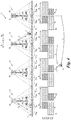
- Figs. 8 and 9 show nodes 11, in which the third channel resource can be assigned adaptively to the needs of the node 11.
- the node 11 reserves high power levels P 1 for a pool of channel resources CR i , e.g., the first three channel resources CR 1 , CR 2 , CR 3 , and lower power levels P 2 for a pool of different channel resources CR i , e.g., the last three channel resources CR 4 , CR 5 , CR 6 , so that the power level scheme has a T-shaped maximum power level outline 16.
- the node 11 checks all of its channel resources CR i and evaluates which one/s is/are used the least.
- the third channel resource/s is/are then allocated to this/these specific channel resource/s CR i with the least usage, here to the channel resources CR 3 , CR 4 .
- the power level/s P 3 for the third channel resource/s CR 3 can again be chosen lower than the first and/or second power level P 1 , P 2 .
- Fig. 9 shows an embodiment of an adaptive node 11, in which an asymmetrical power level scheme is employed.
- the power levels P 1 , P 2 are reserved for pools of each channel resource CR i and each antenna 12, 13, respectively, so that the power level scheme has a Z-shaped maximum power level outline 17.
- the symmetrical third channel resource/s is/are then allocated to this/these channel resource/s CR i , here the channel resources CR 2 and CR 6 .
- all channel resources CR i can be used as third channel resources or even non at all.
- the "rigid" maximum power level outline 16, 17 of a node 11 can be used by a neighbouring node 11 to predict channel resources CR i with high power levels P 1 .
- Such high power channel resources CR i should not be used by said neighbouring node 11 to communicate data 3 at a high power level P 1 in the corresponding direction of that node 11 with the rigid maximum power level outline 16, 17.
Description
- The present invention relates to a node for a cellular network with a linear cell topology for wirelessly communicating with user terminals. The invention further relates to a cellular network comprising a plurality of nodes and a method for communicating between a user terminal and a node.
- A cellular network comprises a plurality of radio transceivers or "nodes", through which users can gain access to the network by means of user terminals. For example, in cellular networks according to the LTE standard, a node is referred to as "eNB" (evolved Node B) and according to the GSM standard as "BTS" (Base Transceiver Station). Each node comprises an antenna and defines a cell, which is delimited by the coverage area of the antenna. If a user terminal is within the coverage area of a node, it can wirelessly communicate with the node by sending and receiving data to and from the node. To increase the capacity of the network for communications with user terminals, so-called frequency reuse schemes are employed, one type of which will be described in the following for the case of a one-dimensional cellular network.
-
Fig. 1 shows a conventionalcellular network 1 with a one-dimensional ("linear") cell topology. In this type of network,nodes 2 communicatedata 3 with user terminals 4, which only travel in one direction dL or the corresponding opposite direction dR, e.g., by riding on atrain 5 on a railway track 6, driving by car on a highway or in a tunnel, et cet. The communication between thenode 2 and the user terminal 4 is conducted by communication standards known in the state of the art, such as 3GPP LTE/LTE-A, IEEE WiMAX 802.17e, GSM, or GSM-R. In such communication standards, the communication channel CH of anode 2 is divided in frequency f and/or time t into multiple channel resources CR1, CR2, ... generally CRi, as can be seen inFig. 2 , which will be described in detail later. - With further reference to
Fig. 1 , eachnode 2 has anomnidirectional antenna 7 mounted on a support 8 and controlled by a transceiver 9. Omnidirectional antennas communicatedata 3 in both directions dL, dR of thenode 2, i.e., it does not matter if a user terminal 4 is located to the left or to the right of anode 2 to establish communication. Eachantenna 7 thus exhibits a coverage area 101 with a range r. Interference occurs when neighbouringnodes 2 use the same channel resource CRi. - For implementing a reuse scheme to enhance network capacity without excessive interferences, i.e., with a low signal-to-interference ratio (SINR), different power levels are employed for same channel resources CRi of neighbouring nodes. Power levels P1, P2 of six exemplary channel resources CR1, CR2, ..., CR6 are shown in the lower half of
Fig. 1 beneath eachnode 2 in the horizontal direction, corresponding to different coverage areas 101 and 102 reached with those different power levels P1, P2, respectively. - For example, a
node 2 uses its first three channel resources CR1, CR2, CR3 to communicatedata 3 at a high power level P1 over a far coverage area 101 with range r, while it uses its last three communication resources CR4, CR5, CR6 to communicatedata 3 at a low power level P2 over a near coverage area 102, e.g., with a range r/2. For user terminals 4 at a distance in the range of r/2 to r from thenode 2,data 3 is communicated in one (or more) of the high power level channel resources CR1, CR2, CR3. For user terminals 4 at a distance in the range of 0 to r/2 from thenode 2,data 3 is communicated in one (or more) of the low power level channel resources CR4, CR5, CR6. The distance of a user terminal 4 can, for example, be measured by means of the received signal strength indication (RSSI) in thenode 2 and/or the user terminal 4. - The two neighbouring
nodes 2 on either side of thenode 2 described before use a reversed scheme for the power levels P1, P2 of the channel resources CRi, i.e., a low power level P2 for the first three communication channels CR1, CR2, CR3, and a high power level P1 for the last three communication channels CR4, CR5, CR6. The one-dimensional network 1 is then constructed by alternatingly using the describednodes 2. Thus, a user terminal 4 near the edge of a cell of anode 2 will communicatedata 3 in a channel resource CRi at a high power level P1 while the neighbouringnode 2 will use only a lower power level P2 for this specific channel resource CRi. Interference from neighbouringnodes 2 is therefore reduced, while the same channel resources CRi can be "reused" by neighbouringnodes 2 to a certain extent. - The described one-dimensional
cellular network 1 has the drawback that the amount ofdata 3 that can be communicated by anode 2 is limited. Furthermore, the interference experienced by user terminals 4 leaves room for improvement. -
WO 2011/100520 , which lies in the field of cellular networks in which nodes cover extended geographical areas in two dimensions, shows cells that have multiple antennas that can employ different transmit powers but cover the same geographical areas. -
US 2016/0037550 A1 shows that for a soft frequency reuse different power levels can be employed for different communication resources. For each power level a separate scheduler is employed. - According to document,
US 2013/301604 A1 (SKOV PETER [CN] ET AL) 14 November 2013 (2013-11-14 FIG. 1 , a plurality ofantenna sites FIG. 1 example each of theantenna sites antenna providing beams 6 and 7. As shown, thedirectional beams 6 and 7 can overlap each other. An appropriate transmission scheme can be used to enable the two antenna site transmission diversity and reception or transmission of two transport blocks. The communications can take place on a single carrier, for example on a frequency resource. - It is an aim of the present invention to overcome the abovementioned drawbacks.
- While several embodiments and/or examples have been disclosed in this description, the subject matter for which protection is sought is strictly and solely limited to those embodiments and/or examples encompassed by the scope of the appended claims. Embodiments and/or examples mentioned in the description that do not fall under the scope of the claims are useful for understanding the invention.
- To this end, in a first aspect the invention provides for a node of the aforementioned type, wherein the node is configured to communicate data in at least a first and a second channel resource of a communication channel, which are separated in at least one of frequency and time, and wherein the node is further configured to employ different power levels for different channel resources, which is distinguished in that:
- the node comprises a first and a second directional antenna, each directed in a different direction and each covering one side of the node,
- wherein the node is configured to act as a single cell of the cellular network by broadcasting a same cell-ID over both antennas, and
- wherein the node is further configured to independently communicate different data over the first and the second antenna in a same channel resource.
- By using two directional antennas, each covering one side of the node, the amount of communicated data can be doubled. This can be used to double the number of user terminals a node can host in its coverage area.
- Even though its throughput or hosting capacity is twice as high, the node still appears as a state of the art node to a user terminal. This is achieved by broadcasting the same cell-ID over both antennas, which leads the user terminals to belief that a conventional node is used. Thus, there is no need to exchange or re-program user terminals to be compatible with the new node of the network, which significantly simplifies implementation.
- Preferably, the node is further configured to employ different power levels for a same channel resource over said first and second antenna. This allows the node not only to communicate twice the amount of data, but also to use different power level schemes for different directions. The usage of different power level schemes in different directions can be used to adapt the node to neighbouring nodes and/or to employ completely new reuse schemes between neighbouring nodes. Apart therefrom, further energy or power savings can be achieved since fewer high power levels can be employed, e.g., if there is only one user terminal close to the edge of the cell, the high power level does not have to be used for both directions. Furthermore, using lower power levels for some channel resources leaves more power for the other channel resources.
- Especially preferably, the node is configured to communicate data
- in the first channel resource over the first antenna at a first power level,
- in the first channel resource over the second antenna at a second power level, which is lower than the first power level,
- in the second channel resource over the first antenna at the second power level, and
- in the second channel resource over the second antenna at the first power level.
- In this way, the node employs a "Z-shaped" power level scheme, which leads to reduced interference for user terminals near the node: For a user terminal at a distance of, e.g., half of the maximum cell range r, i.e., 0,5 r to the node, the second interfering node is now at a greater distance of 3,5 r to the user terminal, while with a reuse scheme according to the state of the art the second interfering node is at a distance of only 2,5 r. Furthermore, when constructing a linear network, nodes of the same type can be employed all in the same way one after the other, which greatly simplifies network planning, production, and installation.
- In a preferred embodiment of the invention, the node is configured to communicate data in a third channel resource over the first and the second antenna, wherein the node is further configured to communicate same data over the first and the second antenna in the third channel resource. By means of the third channel resource, in which data is communicated in parallel over both antennas, an intra-cell "switching" for a user terminal passing from one directional antenna to the other directional antenna of the same node can be greatly facilitated. Right beneath the antennas, the position of a user terminal cannot be reliably determined as to whether it is left or right of the node. Since there is uncertainty over the exact switching moment from one antenna to the other, the node may encounter problems in correctly allocating and attributing communications in same channel resources on either sides of the node to different user terminals. By using dedicated third channel resources with same data on either antenna of the node for very close user terminals, this allows for an undisturbed communication with user terminals passing through the close area of the node.
- Preferably, the node is configured to communicate data in the third channel resource at a power level that is lower than the power levels of the first and second channel resources. Since the third channel resources are used only for user terminals close to the node, the power level of the third channel resources can be reduced as well. Thus, interferences are reduced for user terminals communicating in the same channel resource with a different node.
- The invention envisages two alternative embodiments for allocating the third channel resource. In the first embodiment, the node is configured to use a specific one of all channel resources of the communication channel for the third channel resource on both antennas. The node thus uses a predetermined channel resource, e.g., the lowest frequency and/or time slots, for the third channel resource. Neighbouring nodes then always know, which channel resource is not used for communication with user terminals at a high power level, and can thus themselves proceed to use this channel resource for communication with user terminals in their own cell at a high power level.
- In the alternative embodiment, the node is configured to reserve specific channel resources of all channel resources of the communication channel on both antennas for the channel resources having properties of the first channel resource and the second channel resource, respectively, and the node is further configured to choose and use a specific channel resource from said reserved channel resources for the third channel resource based on a usage of the reserved channel resources. In this embodiment, pools of first and second channel resources can be grouped together for each antenna, such that, e.g., the specific channel resources occupy the first channel resources and the second channel resources occupy the other specific channel resources when the node employs a symmetrical ("T-shaped") power level scheme. Alternatively, an asymmetrical ("Z-shaped") power level scheme can be employed. The node then evaluates, which channel resource is used the least on both antennas, e.g., which channel resource is currently not used at all on both antennas, and assigns the third channel resource/s to this underused channel resource/s.
- Preferably, the node is configured to measure the distance, e.g., by means of received signal strength indication (RSSI) or timing advance (TA), of a user terminal and to assign a channel resource with a corresponding power level to this user terminal to communicate data in this channel resource. By means of this, the node can, e.g., assign the first channel resource with the first power level to a user terminal near the edge of the cell and assign the second channel resource to a user terminal close to the node. Generally, the node can assign the first channel resource to a far user terminal, the second channel resource to a medium user terminal, and the third channel resource to a near user terminal, wherein the terms far, medium, near are relative with respect to each other.
- It is especially preferred if the channel resources are resource blocks according to a 3GPP LTE or LTE-A standard. Resource blocks according to those standards are based on OFDM (orthogonal frequency-division multiplexing) symbols, which are orthogonal to each other. Thus, the resource blocks can be managed and assigned to different user terminals in a simple manner.
- In a second aspect, the invention provides for a cellular network comprising a plurality of nodes according to the embodiments given above, wherein one of the antennas of a first node substantially faces one of the antennas of a second node. Thus, a one-dimensional ("linear") network is created. Preferably, the nodes are arranged in such a way that the coverage areas of the antennas facing each other adjoin or overlap at least partially such that a user terminal moving from one node to another experiences no loss of communication.
- Preferably, the first antenna of the first node substantially faces the second antenna of the second node. Thus, a one-dimensional network of nodes with a substantially "asymmetrical" or "Z-shaped" power level scheme can be created. Such a network has especially low interferences for user terminals near the nodes, as described above. Furthermore, the same type of node can be used for all nodes, which is not possible in state of the art networks. Alternatively, combinations of different nodes can be employed, e.g., a sequence "Z-shaped" - "T-shaped" - inverse "Z-shaped" - inverse "T-shaped".
- Further preferably, nodes assign their channel resources according to the scheme employed by their neighbouring nodes, i.e., power levels are classified as high and medium, with respect to one another, and a node is configured to only communicate data in a channel resource at a high power level over its first antenna if the power level of a channel resource, used by an antenna facing said first antenna, of a neighbouring node is classified as medium. Thus, it is ensured that a user terminal on the edge of the cell does not experience a high interference from a neighbouring node in the same channel resource.
- In a third aspect of the invention, a method for communicating between a user terminal and a node is provided. This method comprises the steps in the following order:
- communicating with the user terminal in the second channel resource over the first antenna when the user terminal is within a first predetermined distance from the node;
- communicating with the user terminal in the third channel resource over the first antenna while simultaneously trying to communicate the same data with the user terminal using the third channel resource over the second antenna when the user terminal is within a second predetermined distance from the node, which is smaller than the second distance; and
- communicating with the user terminal in the third channel resource over the second antenna while simultaneously trying to communicate the same data with the user terminal using the third channel resource over the first antenna when the user terminal is within the second predetermined distance from the node.
- This method avoids an unsteady intra-cell handover from the first antenna to the second antenna by utilizing the third channel resource with the properties as described above. A tradeoff is thus achieved by utilizing a channel resource with an asymmetrical power level scheme with a high data throughput when the user terminal is at a far or medium distance from the node on the one hand and one (or more) third channel resource/s with a symmetrical power level scheme with a lower throughput when the user terminal is near the node on the other hand.
- Furthermore, the method can comprise the subsequent step of communicating with the user terminal in a channel resource having the same power level as the second channel resource over the second antenna when the user terminal is within the first predetermined distance from the node. It is thus ensured that the user terminal re-enters the range of a channel resource having the same power level as before it entered the range of the third channel resource.
- Preferably, the power level of the second channel resource is higher than the power level of the third channel resource. Thus, energy can be saved and interferences can be further reduced for user terminals in different nodes using the same channel resource.
- The invention shall now be explained in more detail below on the basis of preferred exemplary embodiments thereof with reference to the accompanying drawings, in which:
-
Fig. 1 shows a linear cellular network according to the state of the art; -
Fig. 2 shows an exemplary allocation of channel resources; -
Fig. 3 shows a node and a symmetrical channel resource power level scheme according to the invention; -
Fig. 4 shows a linear cellular network having an asymmetrical channel resource power level scheme according to the invention; -
Fig. 5 shows a variant of the channel resource power level scheme of the linear cellular network ofFig. 4 ; -
Figs. 6 and 7 show a node having symmetrical and asymmetrical channel resource power level schemes, respectively, with fixed third channel resources; -
Figs. 8 and 9 show a node having fixed symmetrical and asymmetrical channel resource power level schemes, respectively, with adaptive third channel resources. - With respect to
Fig. 1 , which shows the state of the art, it is referred to the introduction. In the following description ofFigs. 2 to 9 same reference numbers are used for same components as inFig. 1 . - Just as discussed above for the state of the art, the field of the embodiments described below is a linear, one-
dimensional network 1 ofnodes 2 communicatingdata 3 with user terminals 4. Linear or one-dimensional means in this context that thenodes 2 are arranged in a chain-like manner and that thenodes 2 have coverage areas 101, 102 that substantially adjoin or overlap so that a user terminal 4 can move from onenode 2 to the next without interrupting communication. The standard for communication can be as described before, e.g., LTE, LTE-A, IEEE WiMAX 802.16e, GSM, GSM-R, etc, wherein the communication channel CH is divided into multiple channel resources CRi as can be seen inFig. 2 . -
Fig. 2 shows an exemplary definition of the communication channel CH used by thenodes 2 for communication. The channel CH is subdivided in frequency f into frequency bands SF and in time t into time slots ST; a combination of a frequency band SF and a time slot ST is called a channel resource CRi. Of course, the communication channel CH could also be divided only in time t into time slots ST, such as in TDMA (time division multiple access) standards; or be divided only in frequency f into frequency bands SF, such as in FDMA (frequency division multiple access) standards. In LTE, a channel resource CRi is called a "resource block" and carries six or seven OFDM symbols on 12 subcarriers, one subcarrier of one OFDM symbol representing a resource element RE of the resource block CRi. - In
Figs. 1 and3 to 9 , only six exemplary channel resources CR1, ..., CR6 are shown, while in reality any arbitrary number can be employed. -
Fig. 3 shows anode 11 having twodirectional antennas directional antenna own transceiver Data 3 can thus be communicated independently to user terminals 4 in either direction dL, dR of thenode 11, even in a same channel resource CRi. By the term "same" channel resource CRi it is meant that a channel resource CRi of the communication channel CH of the onedirectional antenna 11 is equal in frequency band SF and time slot ST with that of the communication channel CH of the otherdirectional antenna 12. - Each
antenna node 11 can further use a different power level P1, P2 for each channel resource CRi used on eachantenna Fig. 3 , the left and right coverage areas 101L, 102L, 101R, 102R of theantennas node 11 to allow for a continuous communication when a user terminal 4 passes thenode 11. - The
node 11 broadcasts the same cell-identifier (cell-ID) for the entire cellular network cell comprised of the coverage areas 101L, 102L, 101R, 102R over bothantennas node 11 acts as a single cell of thecellular network 1. To this end, the common channels (e.g., in LTE: downlink PSS/SSS/PBCH/RS; uplink RACH) of the communication channel CH can be managed simultaneously for channel resources CRi on both sides of thenode 11 to implement this single-cell behaviour, while the dedicated control/traffic channels (e.g., in LTE: downlink PDCCH/PDSCH; uplink PUCCH/PUSCH) are managed independently to host different pools of user terminals 4 on either side of thenode 11. - As shown in
Fig. 3 , each channel resource CRi can be used with the same power level P1, P2 for eachantenna node 11 to form a symmetrical power level profile, which appears - when power levels P1, P2 are grouped together in the representation - as substantially "T-shaped". It is understood that the term "T-shaped" is used for illustrative purposes and also comprises, for example, inverse "T-shaped" power level schemes. A linearcellular network 1 can then be constructed by arranging nodes in an alternating manner as is shown inFig. 1 , with "T"s and inverted "T"s following one another. Thenode 11 ofFig. 3 , however, can communicate twice the amount ofdata 3 as compared to thenode 2 ofFig. 1 , since communications with user terminals 4 on both sides of thenode 11 are managed independently. -
Fig. 4 shows a linearcellular network 1 withnodes 11, which are structurally the same as thenode 11 shown inFig. 3 . However, thenodes 11 ofFig. 4 employ an asymmetrical power level scheme, meaning that a node can employ different power levels P1, P2 for a same channel resource CRi overdifferent antennas node 11 has a characteristic "Z-shaped" power level profile. It is understood that the term "Z-shaped" is used for illustrative purposes and also comprises, for example, inverse "Z-shaped", i.e., "S-shaped" power level schemes. An exemplary first channel resource CR6 thus has a first power level P1 over thefirst antenna 12 and a second power level P2 over thesecond antenna 13, while an exemplary second channel resource CR1 has the second power level P2 over thefirst antenna 12 and the first power level P1 over thesecond antenna 13. - The examples of
Figs. 3 and4 show channel resources CRi with the same power level schemes grouped together to form said T- and Z-shaped power profiles. However, channel resources CRi can also be arranged in an alternating or random manner in anode 11. - To construct the linear
cellular network 1,identical nodes 11 with asymmetrical power level schemes can be arranged next to each other and do not have to be positioned in an alternating manner, as was the case with nodes as shown inFig. 1 . In contrast toFig. 1 , the linearcellular network 1 further exerts less interferences on user terminals 4 close to anode 11, as shown in the lower halves ofFigs. 1 and4 :
Fig. 1 shows a user terminal 4 at a distance of r/2, i.e., half of the range of the "maximum" coverage area 101 of thenode 11 at the high power level P1, which here corresponds to the edge of the coverage area 102 at the lower power level P2. The user terminal 4 communicates with theclosest node 11 in the channel resource CR6 and experiences interferences when anothernode 11 communicatesdata 3 in the same channel resource CR6 at a high power level P1. Interferences caused bynodes 11 communicatingdata 3 in the same channel resource CR6 but at a lower power level P2 are neglected for this analysis. The user terminal 4 inFig. 1 thus experiences a first interference I1 from anode 11 at a distance of 1,5 r and a second interference I2 from anode 11 at a distance of 2,5 r from the user terminal 4. - In the linear
cellular network 1 ofFig. 4 , however, the user terminal 4 experiences less interference from the secondclosest node 11. Again, the exemplary user terminal 4 is at a distance r/2 from thenode 11, with which it communicates in the channel resource CR6, and experiences interference I1 from theclosest node 11 at a distance of 1,5 r. The user terminal 4 inFig. 4 experiences no interference from thenode 11 to its left since thisnode 11 uses this channel CR6 only at a lower power level P2. The interference I2 from the second interferingnode 11 originates from a distance of 3,5 r to the right of user terminal 4, which yields less interference than the interference I2 experienced over the distance of 2,5 r in the case ofFig. 1 . Therefore, the SINR (signal to interference ratio) of the communications is improved. - Instead of equally distributing power levels P1, P2 to the channel resources CRi as in
Fig. 4 , anode 11 can assign power levels P1, P2 according to its own needs, as is shown inFig. 5 . Anode 11 can thus employ channel resources CRi with symmetrical power levels as well as with asymmetrical power levels. However, anode 11 should only assign a high power level P1 to one of its channel resources CR on oneantenna antenna node 11 employs a lower power level P2 for the same channel resource CRi. In this way, a dynamic power level allocation can be achieved, such that anode 11 can fulfil its own needs as well as comply with restrictions of anothernode 11. - In a further embodiment now described with reference to
Figs. 6 - 9 , which facilitates a smooth passing of a user terminal 4 under thenode 11, thenode 11 communicatesdata 3 symmetrically over bothantennas node 11 and the user terminal 4 according to the distance at which the user terminal 4 is located, i.e., according to whether the user terminal is within one of the far field coverage areas 101L, 101R or one of the near field coverage areas 102L, 102R, the latter also being called "medium" coverage areas in the following. This distance can be directly measured or inferred by means of the received signal strength indication (RSSI) or timing advance (TA). The user terminal 4 is then assigned a channel resource CRi with the respective power level P1, P2 corresponding to the distance of the user terminal 4. - When the user terminal 4 is very close to the
node 11, however, the location of the user terminal 4 cannot be measured accurately anymore due to scatterings and to a lesser degree interferences. Thenode 11 thus does not know anymore whether the left or theright antenna node 11. By communicatingdata 3 over bothantennas node 11, the exact location of the user terminal 4 becomes redundant since the user terminal 4 can potentially communicatedata 3 over bothantennas - The power level P3 for the third channel resource CRi can then be reduced accordingly on both
antennas node 11 within a near or close coverage area 103 of theantennas - When a user terminal 4 passes through the entire coverage area from, e.g., left to right 101L → 102L → 103L → 103R → 102R → 101R of the
exemplary node 11 ofFig. 6 , it will thus normally first communicate over thefirst antenna 12 in one or more first channel resources CR1, CR2 at a high (first) power level P1, then over thefirst antenna 12 in one or more second channel resource CR3, CR4 at a medium (second) power level P2, and then over thefirst antenna 12 in one or more of the third channel resources CR5, CR6 at a low (third) power level P3. Next, the user terminal 4 will leave the coverage area of thefirst antenna 12 and enter the coverage area of thesecond antenna 13 and thus continue to communicate with thenode 11 in one or more of the third channel resources CR5, CR6, however, now with thesecond antenna 13. As the user terminal 4 moves further away from thenode 11, it will then communicate with thesecond antenna 13 at the medium power level P2 in one or more of the second channel resources CR3, CR4 and later with thesecond antenna 13 at the high power level P3 in one or more of the first channel resources CR1, CR2. -
Fig. 6 shows anode 11 that employs a symmetrical power level scheme, wherein power levels P1, P2, P3 are assigned to pools of specific channel resources CRi, and especially the third channel resource is assigned to specific channel resources CRi dedicated therefor, such as, e.g., the last two channel resources CR5, CR6. -
Fig. 7 shows anode 11 employing an asymmetrical power level scheme, wherein the power levels P1, P2, P3 are assigned to pools of specific channel resources CRi for eachantenna Fig. 6 , the third channel resource is assigned to the last two channel resources CR5, CR6. -
Figs. 8 and 9 show nodes 11, in which the third channel resource can be assigned adaptively to the needs of thenode 11. InFig. 8 , thenode 11 reserves high power levels P1 for a pool of channel resources CRi, e.g., the first three channel resources CR1, CR2, CR3, and lower power levels P2 for a pool of different channel resources CRi, e.g., the last three channel resources CR4, CR5, CR6, so that the power level scheme has a T-shaped maximumpower level outline 16. When a user terminal 4 approaches thenode 11 to pass underneath it, thenode 11 checks all of its channel resources CRi and evaluates which one/s is/are used the least. The third channel resource/s is/are then allocated to this/these specific channel resource/s CRi with the least usage, here to the channel resources CR3, CR4. Of course, the power level/s P3 for the third channel resource/s CR3 can again be chosen lower than the first and/or second power level P1, P2. -
Fig. 9 shows an embodiment of anadaptive node 11, in which an asymmetrical power level scheme is employed. The power levels P1, P2 are reserved for pools of each channel resource CRi and eachantenna power level outline 17. Again, it is evaluated which channel resource/s CRi is/are used the least on bothantennas - The "rigid" maximum
power level outline node 11 can be used by a neighbouringnode 11 to predict channel resources CRi with high power levels P1. Such high power channel resources CRi should not be used by said neighbouringnode 11 to communicatedata 3 at a high power level P1 in the corresponding direction of thatnode 11 with the rigid maximumpower level outline - The invention is not restricted to the specific embodiments described in detail herein, but encompasses all variants, combinations and modifications thereof that fall within the framework of the appended claims.
Claims (15)
- Node for a cellular network with a linear cell topology for wirelessly communicating with user terminals, wherein the network with the linear cell topology has nodes (2) that are arranged in a chain-like manner and have coverage areas (101, 102) that substantially adjoin or overlap so that a user terminal (4) can move from one node (2) to the next without interrupting communication,
wherein the node (11) has a single support (8) and is configured to communicate data (3) in at least a first and a second channel resource of channel resources (CRi) of a communication channel (CH), which are separated in at least one of frequency (f) and time (t), and
wherein the node (11) is further configured to employ different power levels (P1, P2) for different channel resources of the channel resources (CRi)of the communication channel, wherein the node (11) comprises a first and a second directional antenna (12, 13) mounted on the single support (8), each directed in a different direction (dL, dR) and each covering one side of the node (11),
wherein the node (11) is configured to act as a single cell of the cellular network (1) by broadcasting a same cell-ID over both antennas (12, 13), and
wherein the node (11) is further configured to independently communicate different data (3) over the first and the second antenna (12, 13) in a same channel resource of the channel resources (CRi)of the communication channel. . - Node according to claim 1, wherein the node (11) is further configured to employ different power levels (P1, P2) for a same channel resource (CRi) over said first and second antenna (12, 13).
- Node according to claim 1 or 2, wherein the node (11) is configured to communicate data (3)- in the first channel resource (CR6) over the first antenna (12) at a first power level (P1),- in the first channel resource (CR6) over the second antenna (13) at a second power level (P2), which is lower than the first power level (P1),- in the second channel resource (CR1) over the first antenna (12) at the second power level (P2), and- in the second channel resource (CR1) over the second antenna (13) at the first power level (P1).
- Node according to any one of the claims 1 to 3, wherein the node (11) is configured to communicate data (3) in a third channel resource (CRi) over the first and the second antenna (12, 13),
wherein the node (11) is further configured to communicate same data (3) over the first and the second antenna (12, 13) in the third channel resource (CRi). - Node according to claim 4, wherein the node is configured to communicate data (3) in the third channel resource (CRi) at a power level (P3) that is lower than the power levels (P1, P2) of the first and second channel resources (CRi) .
- Node according to claim 4 or 5, wherein the node is configured to use a specific one of all channel resources (CRi) of the communication channel (CH) for the third channel resource (CRi) on both antennas (12, 13).
- Node according to claim 4 or 5, wherein the node (11) is configured to reserve specific channel resources (CRi) of the communication channel (CH) on both antennas (12, 13) for the channel resources (CRi) having properties of the first channel resource (CRi) and the second channel resource (CRi) respectively, and
wherein the node (11) is further configured to choose and use a specific channel resource (CRi) from said reserved channel resources (CRi) for the third channel resource (CRi) based on a usage of the reserved channel resources (CRi). - Node according to any one of the claims 1 to 7, wherein the node (11) is configured to measure the distance of a user terminal (4), preferably by means of a received signal strength indication or a timing advance, and to assign a channel resource (CRi) with a corresponding power level (P1, P2, P3) to this user terminal (4) to communicate data (3) in this channel resource (CRi).
- Node according to any one of the claims 1 to 8, wherein the channel resources (CRi) are resource blocks according to a 3GPP LTE or LTE-A standard.
- Cellular network comprising a plurality of nodes (11) according to any one of the claims 1 to 9, wherein one of the antennas (12, 13) of a first node (11) substantially faces one of the antennas (12, 13) of a second node (11).
- Cellular network according to claim 10 comprising nodes according to claim 3, wherein the first antenna (12) of the first node (11) substantially faces the second antenna (13) of the second node (11).
- Cellular network according to claim 10 or 11, wherein power levels (P1, P2) are classified as high and medium, with respect to one another, and
wherein a node (11) is configured to only communicate data (3) in a channel resource (CRi) at a high power level (P1) over its first antenna (12) if the power level (P2) of a channel resource (CRi), used by an antenna (13) facing said first antenna (12), of a neighbouring node (11) is classified as medium. - Method for communicating between a user terminal and a node according to any one of the claims 1 to 9 in combination with claim 4, comprising the steps in the following order:communicating with the user terminal (4) in the second channel resource (CRi) over the first antenna (12) when the user terminal (4) is within a second predetermined distance (102L) from the node (11);communicating with the user terminal (4) in the third channel resource (CRi) over the first antenna (12) while simultaneously trying to communicate the same data (3) with the user terminal (4) using the third channel resource (CRi) over the second antenna (13) when the user terminal (4) is within a third predetermined distance (103) from the node (11), which is smaller than the second distance (102L); andcommunicating with the user terminal (4) in the third channel resource (CRi) over the second antenna (13) while simultaneously trying to communicate the same data (3) with the user terminal (4) using the third channel resource (CRi) over the first antenna (12) when the user terminal (4) is within the third predetermined distance (103) from the node (11).
- Method according to claim 13, comprising the subsequent step:
communicating with the user terminal (4) in a channel resource (CRi) having the same power level (P2) as the second channel resource (CRi) over the second antenna (13) when the user terminal (4) is within the second predetermined distance (102R) from the node (11). - Method according to claim 13, wherein the power level (P2) of the second channel resource (CRi) is higher than the power level (P3) of the third channel resource (CRi).
Priority Applications (3)
| Application Number | Priority Date | Filing Date | Title |
|---|---|---|---|
| EP16166025.3A EP3236591B1 (en) | 2016-04-19 | 2016-04-19 | Cellular network with a linear cell topology, node and method therefor |
| PL16166025T PL3236591T3 (en) | 2016-04-19 | 2016-04-19 | Cellular network with a linear cell topology, node and method therefor |
| ES16166025T ES2753417T3 (en) | 2016-04-19 | 2016-04-19 | Cellular network with a linear cell topology, node and procedure for it |
Applications Claiming Priority (1)
| Application Number | Priority Date | Filing Date | Title |
|---|---|---|---|
| EP16166025.3A EP3236591B1 (en) | 2016-04-19 | 2016-04-19 | Cellular network with a linear cell topology, node and method therefor |
Publications (2)
| Publication Number | Publication Date |
|---|---|
| EP3236591A1 EP3236591A1 (en) | 2017-10-25 |
| EP3236591B1 true EP3236591B1 (en) | 2019-07-31 |
Family
ID=55808968
Family Applications (1)
| Application Number | Title | Priority Date | Filing Date |
|---|---|---|---|
| EP16166025.3A Active EP3236591B1 (en) | 2016-04-19 | 2016-04-19 | Cellular network with a linear cell topology, node and method therefor |
Country Status (3)
| Country | Link |
|---|---|
| EP (1) | EP3236591B1 (en) |
| ES (1) | ES2753417T3 (en) |
| PL (1) | PL3236591T3 (en) |
Families Citing this family (2)
| Publication number | Priority date | Publication date | Assignee | Title |
|---|---|---|---|---|
| CN110113776B (en) * | 2019-04-29 | 2022-06-10 | 北京六捷科技有限公司 | Wireless network coverage trend prediction method and device based on big data technology |
| CN113826423B (en) * | 2019-08-09 | 2023-07-11 | 华为技术有限公司 | Method and device for data transmission |
Citations (1)
| Publication number | Priority date | Publication date | Assignee | Title |
|---|---|---|---|---|
| US20130301604A1 (en) * | 2010-12-22 | 2013-11-14 | Nokia Siemens Networks Oy | Allocation of Resources |
Family Cites Families (2)
| Publication number | Priority date | Publication date | Assignee | Title |
|---|---|---|---|---|
| US8305987B2 (en) * | 2010-02-12 | 2012-11-06 | Research In Motion Limited | Reference signal for a coordinated multi-point network implementation |
| CA3167284A1 (en) * | 2014-06-09 | 2015-12-17 | Airvana Lp | Radio access networks |
-
2016
- 2016-04-19 PL PL16166025T patent/PL3236591T3/en unknown
- 2016-04-19 ES ES16166025T patent/ES2753417T3/en active Active
- 2016-04-19 EP EP16166025.3A patent/EP3236591B1/en active Active
Patent Citations (1)
| Publication number | Priority date | Publication date | Assignee | Title |
|---|---|---|---|---|
| US20130301604A1 (en) * | 2010-12-22 | 2013-11-14 | Nokia Siemens Networks Oy | Allocation of Resources |
Also Published As
| Publication number | Publication date |
|---|---|
| ES2753417T3 (en) | 2020-04-08 |
| EP3236591A1 (en) | 2017-10-25 |
| PL3236591T3 (en) | 2020-03-31 |
Similar Documents
| Publication | Publication Date | Title |
|---|---|---|
| US20210144559A1 (en) | Method and system for soft frequency reuse in a distributed antenna system | |
| KR102435887B1 (en) | Resource management method and apparatus | |
| KR101988574B1 (en) | Method for receiving signals and wireless device thereof | |
| KR102045971B1 (en) | A method for connecting to a base station with flexible bandwidth | |
| US7313126B2 (en) | Control system and multiple access method in wireless communication system | |
| EP3454480B1 (en) | Flexible subframes | |
| DK1997334T3 (en) | Measuring supported dynamic frequency re-use in mobile telecommunications networks | |
| US10462804B2 (en) | Method and apparatus for supporting coexistence in unlicensed band among cells of different operators in wireless communication system | |
| JP5651180B2 (en) | Radio base station and communication control method | |
| US9844048B2 (en) | Resource allocation system and control method | |
| EP2543208B1 (en) | Methods for mitigating the control channel interference between a macro cell and a small cell | |
| US20150223253A1 (en) | Radio communication system, high-power base station, low-power base station, and communication control method | |
| JP6153350B2 (en) | Wireless base station, user terminal, wireless communication system, and wireless communication method | |
| US20100220670A1 (en) | Method for Scheduling to Reduce Inter-Cell Interference for Voice Communication in OFDMA | |
| US20160057768A1 (en) | Method and network node for downlink scheduling in a mobile communication network | |
| KR20190132471A (en) | Method and device for reporting power headroom | |
| KR20190131561A (en) | Method for performing blind decoding of physical sidelink control channel of terminal in wireless communication system and terminal using the method | |
| JP5697483B2 (en) | Wireless communication system, wireless base station, and communication control method | |
| EP3236591B1 (en) | Cellular network with a linear cell topology, node and method therefor | |
| US11190322B2 (en) | Method for allocating resources for base station terminal in wireless communication system, and communication apparatus utilizing said method | |
| EP2079257B1 (en) | Time based and hybrid resource partitioning | |
| WO1996007284A1 (en) | A cellular telecommunications method and network | |
| JP5555566B2 (en) | Radio base station and communication control method | |
| EP3282764B1 (en) | A communication system for a linear cellular network | |
| JP5504083B2 (en) | Radio base station and communication control method |
Legal Events
| Date | Code | Title | Description |
|---|---|---|---|
| STAA | Information on the status of an ep patent application or granted ep patent |
Free format text: STATUS: EXAMINATION IS IN PROGRESS |
|
| PUAI | Public reference made under article 153(3) epc to a published international application that has entered the european phase |
Free format text: ORIGINAL CODE: 0009012 |
|
| 17P | Request for examination filed |
Effective date: 20170102 |
|
| AK | Designated contracting states |
Kind code of ref document: A1 Designated state(s): AL AT BE BG CH CY CZ DE DK EE ES FI FR GB GR HR HU IE IS IT LI LT LU LV MC MK MT NL NO PL PT RO RS SE SI SK SM TR |
|
| AX | Request for extension of the european patent |
Extension state: BA ME |
|
| GRAP | Despatch of communication of intention to grant a patent |
Free format text: ORIGINAL CODE: EPIDOSNIGR1 |
|
| STAA | Information on the status of an ep patent application or granted ep patent |
Free format text: STATUS: GRANT OF PATENT IS INTENDED |
|
| INTG | Intention to grant announced |
Effective date: 20190426 |
|
| GRAS | Grant fee paid |
Free format text: ORIGINAL CODE: EPIDOSNIGR3 |
|
| GRAA | (expected) grant |
Free format text: ORIGINAL CODE: 0009210 |
|
| STAA | Information on the status of an ep patent application or granted ep patent |
Free format text: STATUS: THE PATENT HAS BEEN GRANTED |
|
| AK | Designated contracting states |
Kind code of ref document: B1 Designated state(s): AL AT BE BG CH CY CZ DE DK EE ES FI FR GB GR HR HU IE IS IT LI LT LU LV MC MK MT NL NO PL PT RO RS SE SI SK SM TR |
|
| REG | Reference to a national code |
Ref country code: CH Ref legal event code: EP Ref country code: GB Ref legal event code: FG4D |
|
| REG | Reference to a national code |
Ref country code: DE Ref legal event code: R096 Ref document number: 602016017583 Country of ref document: DE |
|
| REG | Reference to a national code |
Ref country code: AT Ref legal event code: REF Ref document number: 1162054 Country of ref document: AT Kind code of ref document: T Effective date: 20190815 |
|
| REG | Reference to a national code |
Ref country code: IE Ref legal event code: FG4D |
|
| REG | Reference to a national code |
Ref country code: NL Ref legal event code: MP Effective date: 20190731 |
|
| REG | Reference to a national code |
Ref country code: LT Ref legal event code: MG4D |
|
| PG25 | Lapsed in a contracting state [announced via postgrant information from national office to epo] |
Ref country code: NL Free format text: LAPSE BECAUSE OF FAILURE TO SUBMIT A TRANSLATION OF THE DESCRIPTION OR TO PAY THE FEE WITHIN THE PRESCRIBED TIME-LIMIT Effective date: 20190731 Ref country code: HR Free format text: LAPSE BECAUSE OF FAILURE TO SUBMIT A TRANSLATION OF THE DESCRIPTION OR TO PAY THE FEE WITHIN THE PRESCRIBED TIME-LIMIT Effective date: 20190731 Ref country code: BG Free format text: LAPSE BECAUSE OF FAILURE TO SUBMIT A TRANSLATION OF THE DESCRIPTION OR TO PAY THE FEE WITHIN THE PRESCRIBED TIME-LIMIT Effective date: 20191031 Ref country code: SE Free format text: LAPSE BECAUSE OF FAILURE TO SUBMIT A TRANSLATION OF THE DESCRIPTION OR TO PAY THE FEE WITHIN THE PRESCRIBED TIME-LIMIT Effective date: 20190731 Ref country code: FI Free format text: LAPSE BECAUSE OF FAILURE TO SUBMIT A TRANSLATION OF THE DESCRIPTION OR TO PAY THE FEE WITHIN THE PRESCRIBED TIME-LIMIT Effective date: 20190731 Ref country code: NO Free format text: LAPSE BECAUSE OF FAILURE TO SUBMIT A TRANSLATION OF THE DESCRIPTION OR TO PAY THE FEE WITHIN THE PRESCRIBED TIME-LIMIT Effective date: 20191031 Ref country code: PT Free format text: LAPSE BECAUSE OF FAILURE TO SUBMIT A TRANSLATION OF THE DESCRIPTION OR TO PAY THE FEE WITHIN THE PRESCRIBED TIME-LIMIT Effective date: 20191202 Ref country code: LT Free format text: LAPSE BECAUSE OF FAILURE TO SUBMIT A TRANSLATION OF THE DESCRIPTION OR TO PAY THE FEE WITHIN THE PRESCRIBED TIME-LIMIT Effective date: 20190731 |
|
| PG25 | Lapsed in a contracting state [announced via postgrant information from national office to epo] |
Ref country code: RS Free format text: LAPSE BECAUSE OF FAILURE TO SUBMIT A TRANSLATION OF THE DESCRIPTION OR TO PAY THE FEE WITHIN THE PRESCRIBED TIME-LIMIT Effective date: 20190731 Ref country code: AL Free format text: LAPSE BECAUSE OF FAILURE TO SUBMIT A TRANSLATION OF THE DESCRIPTION OR TO PAY THE FEE WITHIN THE PRESCRIBED TIME-LIMIT Effective date: 20190731 Ref country code: LV Free format text: LAPSE BECAUSE OF FAILURE TO SUBMIT A TRANSLATION OF THE DESCRIPTION OR TO PAY THE FEE WITHIN THE PRESCRIBED TIME-LIMIT Effective date: 20190731 Ref country code: IS Free format text: LAPSE BECAUSE OF FAILURE TO SUBMIT A TRANSLATION OF THE DESCRIPTION OR TO PAY THE FEE WITHIN THE PRESCRIBED TIME-LIMIT Effective date: 20191130 Ref country code: GR Free format text: LAPSE BECAUSE OF FAILURE TO SUBMIT A TRANSLATION OF THE DESCRIPTION OR TO PAY THE FEE WITHIN THE PRESCRIBED TIME-LIMIT Effective date: 20191101 |
|
| REG | Reference to a national code |
Ref country code: ES Ref legal event code: FG2A Ref document number: 2753417 Country of ref document: ES Kind code of ref document: T3 Effective date: 20200408 |
|
| PG25 | Lapsed in a contracting state [announced via postgrant information from national office to epo] |
Ref country code: DK Free format text: LAPSE BECAUSE OF FAILURE TO SUBMIT A TRANSLATION OF THE DESCRIPTION OR TO PAY THE FEE WITHIN THE PRESCRIBED TIME-LIMIT Effective date: 20190731 Ref country code: RO Free format text: LAPSE BECAUSE OF FAILURE TO SUBMIT A TRANSLATION OF THE DESCRIPTION OR TO PAY THE FEE WITHIN THE PRESCRIBED TIME-LIMIT Effective date: 20190731 Ref country code: IT Free format text: LAPSE BECAUSE OF FAILURE TO SUBMIT A TRANSLATION OF THE DESCRIPTION OR TO PAY THE FEE WITHIN THE PRESCRIBED TIME-LIMIT Effective date: 20190731 Ref country code: EE Free format text: LAPSE BECAUSE OF FAILURE TO SUBMIT A TRANSLATION OF THE DESCRIPTION OR TO PAY THE FEE WITHIN THE PRESCRIBED TIME-LIMIT Effective date: 20190731 |
|
| PG25 | Lapsed in a contracting state [announced via postgrant information from national office to epo] |
Ref country code: IS Free format text: LAPSE BECAUSE OF FAILURE TO SUBMIT A TRANSLATION OF THE DESCRIPTION OR TO PAY THE FEE WITHIN THE PRESCRIBED TIME-LIMIT Effective date: 20200224 Ref country code: SM Free format text: LAPSE BECAUSE OF FAILURE TO SUBMIT A TRANSLATION OF THE DESCRIPTION OR TO PAY THE FEE WITHIN THE PRESCRIBED TIME-LIMIT Effective date: 20190731 Ref country code: CZ Free format text: LAPSE BECAUSE OF FAILURE TO SUBMIT A TRANSLATION OF THE DESCRIPTION OR TO PAY THE FEE WITHIN THE PRESCRIBED TIME-LIMIT Effective date: 20190731 Ref country code: SK Free format text: LAPSE BECAUSE OF FAILURE TO SUBMIT A TRANSLATION OF THE DESCRIPTION OR TO PAY THE FEE WITHIN THE PRESCRIBED TIME-LIMIT Effective date: 20190731 |
|
| REG | Reference to a national code |
Ref country code: DE Ref legal event code: R097 Ref document number: 602016017583 Country of ref document: DE |
|
| PLBE | No opposition filed within time limit |
Free format text: ORIGINAL CODE: 0009261 |
|
| STAA | Information on the status of an ep patent application or granted ep patent |
Free format text: STATUS: NO OPPOSITION FILED WITHIN TIME LIMIT |
|
| PG2D | Information on lapse in contracting state deleted |
Ref country code: IS |
|
| PG25 | Lapsed in a contracting state [announced via postgrant information from national office to epo] |
Ref country code: IS Free format text: LAPSE BECAUSE OF FAILURE TO SUBMIT A TRANSLATION OF THE DESCRIPTION OR TO PAY THE FEE WITHIN THE PRESCRIBED TIME-LIMIT Effective date: 20191030 |
|
| 26N | No opposition filed |
Effective date: 20200603 |
|
| PG25 | Lapsed in a contracting state [announced via postgrant information from national office to epo] |
Ref country code: SI Free format text: LAPSE BECAUSE OF FAILURE TO SUBMIT A TRANSLATION OF THE DESCRIPTION OR TO PAY THE FEE WITHIN THE PRESCRIBED TIME-LIMIT Effective date: 20190731 |
|
| PG25 | Lapsed in a contracting state [announced via postgrant information from national office to epo] |
Ref country code: MC Free format text: LAPSE BECAUSE OF FAILURE TO SUBMIT A TRANSLATION OF THE DESCRIPTION OR TO PAY THE FEE WITHIN THE PRESCRIBED TIME-LIMIT Effective date: 20190731 |
|
| REG | Reference to a national code |
Ref country code: CH Ref legal event code: PL |
|
| REG | Reference to a national code |
Ref country code: AT Ref legal event code: UEP Ref document number: 1162054 Country of ref document: AT Kind code of ref document: T Effective date: 20190731 |
|
| PG25 | Lapsed in a contracting state [announced via postgrant information from national office to epo] |
Ref country code: LU Free format text: LAPSE BECAUSE OF NON-PAYMENT OF DUE FEES Effective date: 20200419 Ref country code: LI Free format text: LAPSE BECAUSE OF NON-PAYMENT OF DUE FEES Effective date: 20200430 Ref country code: CH Free format text: LAPSE BECAUSE OF NON-PAYMENT OF DUE FEES Effective date: 20200430 |
|
| REG | Reference to a national code |
Ref country code: BE Ref legal event code: MM Effective date: 20200430 |
|
| PG25 | Lapsed in a contracting state [announced via postgrant information from national office to epo] |
Ref country code: BE Free format text: LAPSE BECAUSE OF NON-PAYMENT OF DUE FEES Effective date: 20200430 |
|
| PG25 | Lapsed in a contracting state [announced via postgrant information from national office to epo] |
Ref country code: IE Free format text: LAPSE BECAUSE OF NON-PAYMENT OF DUE FEES Effective date: 20200419 |
|
| PG25 | Lapsed in a contracting state [announced via postgrant information from national office to epo] |
Ref country code: MT Free format text: LAPSE BECAUSE OF FAILURE TO SUBMIT A TRANSLATION OF THE DESCRIPTION OR TO PAY THE FEE WITHIN THE PRESCRIBED TIME-LIMIT Effective date: 20190731 Ref country code: CY Free format text: LAPSE BECAUSE OF FAILURE TO SUBMIT A TRANSLATION OF THE DESCRIPTION OR TO PAY THE FEE WITHIN THE PRESCRIBED TIME-LIMIT Effective date: 20190731 |
|
| PG25 | Lapsed in a contracting state [announced via postgrant information from national office to epo] |
Ref country code: MK Free format text: LAPSE BECAUSE OF FAILURE TO SUBMIT A TRANSLATION OF THE DESCRIPTION OR TO PAY THE FEE WITHIN THE PRESCRIBED TIME-LIMIT Effective date: 20190731 |
|
| PGFP | Annual fee paid to national office [announced via postgrant information from national office to epo] |
Ref country code: FR Payment date: 20230417 Year of fee payment: 8 Ref country code: ES Payment date: 20230517 Year of fee payment: 8 Ref country code: DE Payment date: 20230418 Year of fee payment: 8 |
|
| PGFP | Annual fee paid to national office [announced via postgrant information from national office to epo] |
Ref country code: TR Payment date: 20230417 Year of fee payment: 8 Ref country code: PL Payment date: 20230414 Year of fee payment: 8 Ref country code: AT Payment date: 20230321 Year of fee payment: 8 |
|
| PGFP | Annual fee paid to national office [announced via postgrant information from national office to epo] |
Ref country code: GB Payment date: 20230420 Year of fee payment: 8 |