EP3236534A1 - Connector terminal - Google Patents
Connector terminal Download PDFInfo
- Publication number
- EP3236534A1 EP3236534A1 EP17157056.7A EP17157056A EP3236534A1 EP 3236534 A1 EP3236534 A1 EP 3236534A1 EP 17157056 A EP17157056 A EP 17157056A EP 3236534 A1 EP3236534 A1 EP 3236534A1
- Authority
- EP
- European Patent Office
- Prior art keywords
- connector terminal
- side contact
- contact portions
- base
- counter connector
- Prior art date
- Legal status (The legal status is an assumption and is not a legal conclusion. Google has not performed a legal analysis and makes no representation as to the accuracy of the status listed.)
- Granted
Links
Images


Classifications
-
- H—ELECTRICITY
- H01—ELECTRIC ELEMENTS
- H01R—ELECTRICALLY-CONDUCTIVE CONNECTIONS; STRUCTURAL ASSOCIATIONS OF A PLURALITY OF MUTUALLY-INSULATED ELECTRICAL CONNECTING ELEMENTS; COUPLING DEVICES; CURRENT COLLECTORS
- H01R13/00—Details of coupling devices of the kinds covered by groups H01R12/70 or H01R24/00 - H01R33/00
- H01R13/02—Contact members
- H01R13/10—Sockets for co-operation with pins or blades
- H01R13/11—Resilient sockets
- H01R13/113—Resilient sockets co-operating with pins or blades having a rectangular transverse section
-
- H—ELECTRICITY
- H01—ELECTRIC ELEMENTS
- H01R—ELECTRICALLY-CONDUCTIVE CONNECTIONS; STRUCTURAL ASSOCIATIONS OF A PLURALITY OF MUTUALLY-INSULATED ELECTRICAL CONNECTING ELEMENTS; COUPLING DEVICES; CURRENT COLLECTORS
- H01R13/00—Details of coupling devices of the kinds covered by groups H01R12/70 or H01R24/00 - H01R33/00
- H01R13/02—Contact members
- H01R13/15—Pins, blades or sockets having separate spring member for producing or increasing contact pressure
-
- H—ELECTRICITY
- H01—ELECTRIC ELEMENTS
- H01R—ELECTRICALLY-CONDUCTIVE CONNECTIONS; STRUCTURAL ASSOCIATIONS OF A PLURALITY OF MUTUALLY-INSULATED ELECTRICAL CONNECTING ELEMENTS; COUPLING DEVICES; CURRENT COLLECTORS
- H01R13/00—Details of coupling devices of the kinds covered by groups H01R12/70 or H01R24/00 - H01R33/00
- H01R13/02—Contact members
- H01R13/22—Contacts for co-operating by abutting
- H01R13/24—Contacts for co-operating by abutting resilient; resiliently-mounted
- H01R13/2464—Contacts for co-operating by abutting resilient; resiliently-mounted characterized by the contact point
- H01R13/2492—Contacts for co-operating by abutting resilient; resiliently-mounted characterized by the contact point multiple contact points
-
- H—ELECTRICITY
- H01—ELECTRIC ELEMENTS
- H01R—ELECTRICALLY-CONDUCTIVE CONNECTIONS; STRUCTURAL ASSOCIATIONS OF A PLURALITY OF MUTUALLY-INSULATED ELECTRICAL CONNECTING ELEMENTS; COUPLING DEVICES; CURRENT COLLECTORS
- H01R2201/00—Connectors or connections adapted for particular applications
- H01R2201/26—Connectors or connections adapted for particular applications for vehicles
Definitions
- the present invention relates to a connector terminal, particularly to a connector terminal that, when being fitted with a counter connector terminal, which has a flat plate shape and has top and bottom surfaces, along a fitting axis so that its contact portions corresponding to the top and bottom surfaces of the counter connector terminal come into contact with the top and bottom surfaces, enables the electric connection with the counter connector terminal to be established.
- a connector In electric wiring using, for instance, a wire harness for vehicles, a connector has heretofore widely been used which establishes the electric connection when a plug terminal in a flat plate shape is inserted into a socket terminal in a box shape so that the plug terminal is sandwiched from top and bottom between a plurality of contact portions of the socket terminal.
- JP 2013-98088 A discloses a connector terminal in which a socket terminal 1 has three elongate convex contact portions 2A to 2C formed on an inner facing contact surface 2 and one dome-shaped embossed contact 3A formed on a resilient contact piece 3 and a flat plug terminal 4 is sandwiched between the elongate convex contact portions 2A to 2C and the dome-shaped embossed contact 3A, as shown in FIG. 11 .
- the three elongate convex contact portions 2A to 2C of the socket terminal 1 are disposed on the inner facing contact surface 2 so as to be located at three vertices of a triangle, and the dome-shaped embossed contact 3A is located in a central portion of the triangle formed by the three elongate convex contact portions 2A to 2C and at a substantially equal distance from any of the three elongate convex contact portions 2A to 2C.
- the elongate convex contact portions 2A to 2C of the socket terminal 1 come into contact with a top surface 4A of the plug terminal 4, while the dome-shaped embossed contact 3A of the socket terminal 1 comes into contact with a bottom surface 4B of the plug terminal 4, whereby the electric connection is established between the socket terminal 1 and the plug terminal 4.
- the present invention aims at removing the drawback described above and providing a connector terminal that can reduce the variance in contact resistance among a plurality of contact portions that make contact with a counter connector terminal in a flat plate shape, thereby preventing heat from being locally generated.
- a connector terminal according to the present invention is one that, when being fitted along a fitting axis with a counter connector terminal in a flat plate shape having a top surface and a bottom surface such that its contact points separately corresponding to the top surface and the bottom surface of the counter connector terminal come into contact with the top surface and the bottom surface, establishes an electric connection with the counter connector terminal, and the connector terminal comprises:
- a connector terminal 11 is a socket terminal including a socket portion 12 in a box shape having formed therein a counter connector terminal accommodating portion S, and a counter connector terminal 21 is a plug terminal in a flat plate shape.
- the connector terminal 11 and the counter connector terminal 21 are fitted with each other, thus establishing the electric connection.
- the connector terminal 11 includes an electric wire holding portion 13 that is formed at the back end of the socket portion 12 along the fitting axis C1 to be integral with the socket portion 12.
- the socket portion 12 includes a base member 14 integral with the electric wire holding portion 13 and a housing 15 retaining the base member 14 and covering the outer periphery of the base member 14.
- the base member 14 and the housing 15 are each made of a conductive material such as a metal.
- the base member 14 has a flat plate shape.
- the housing 15 includes a bottom plate portion 16, a ceiling portion 17 facing the bottom plate portion 16 in parallel therewith, and a pair of lateral wall portions 18 each of which connects either lateral end of the bottom plate portion 16 to the corresponding lateral end of the ceiling portion 17.
- the housing 15 is thus in a box shape which is open at the front and back ends in the direction of the fitting axis C1.
- the base member 14 is fixed to a surface of the bottom plate portion 16 of the housing 15 configured as above.
- the open front end of the housing 15 constitutes an insertion port 19 for receiving the counter connector terminal 21.
- a plane along which the bottom plate portion 16 and ceiling portion 17 of the housing 15 extend is called “XY plane,” a plane along which the lateral wall portions 18 extend “YZ plane,” a direction in which the fitting axis C1 extends from the socket portion 12 toward the electric wire holding portion 13 "+Y direction,” and a direction from the bottom plate portion 16 of the housing 15 toward the ceiling portion 17 thereof "+Z direction.”
- the counter connector terminal 21 is of a flat plate shape having a uniform thickness and extending along an XY plane.
- the counter connector terminal 21 includes a top surface 21A extending along the XY plane and facing in the +Z direction and a bottom surface 21B extending along the XY plane in parallel with the top surface 21A and facing in the -Z direction.
- three bottom side contact portions 14A to 14C are formed on a surface of the base member 14 in a flat plate shape.
- the three bottom side contact portions 14A to 14C are linear contact portions projecting from the surface of the base member 14 in the +Z direction and extending along the Y direction, that is, the fitting axis C1, and are non-spring contact portions that make contact with the bottom surface 21B of the counter connector terminal 21 in the fitted state.
- the bottom side contact portions 14A to 14C are arranged to form an isosceles triangle T in an XY plane with the center of the bottom side contact portion 14A being set as a vertex A and a line segment connecting the centers of the remaining bottom side contact portions 14B and 14C being set as a base BC.
- the base BC of the isosceles triangle T extends in the X direction, and a median AM connecting a midpoint M of the base BC to the vertex A of the isosceles triangle T extends in the Y direction.
- the isosceles triangle T is symmetrical with respect to a YZ plane passing through the median AM.
- the median AM of the isosceles triangle T is positioned in the same YZ plane as the YZ plane passing through the fitting axis C1, and the three bottom side contact portions 14A to 14C are arranged symmetrically with respect to the YZ plane passing through the fitting axis C1, i.e., a perpendicular plane that is perpendicular to the top surface 21A of the counter connector terminal 21 in the fitted state and passes through the fitting axis C1.
- the structure of the housing 15 is shown in FIG. 3 .
- a pair of claws 16A projecting in the +Z direction and being slightly bent toward the +Y direction are formed at the -Y direction-side end of the bottom plate portion 16 of the housing 15, and a pair of openings 18A lying adjacent to the bottom plate portion 16 and opening along the Y direction are separately formed in the pair of lateral wall portions 18 of the housing 15.
- the pair of claws 16A and the pair of openings 18A serve to retain the base member 14 in the housing 15.
- the base member 14 is fixed to the inside of the housing 15 as shown in FIG. 1 with the -Y direction-side end of the base member 14 being caught on the pair of claws 16A and both lateral edges of the base member 14 being inserted in the pair of openings 18A.
- a top side contact portion 15A that makes contact with the top surface 21A of the counter connector terminal 21 in the fitted state is formed in the housing 15.
- FIG. 4 is a drawing showing the inside of the housing 15 with a +X direction-side half of the ceiling portion 17 of the housing 15 and, of the pair of lateral wall portions 18, a +X direction-side lateral wall portion 18 being removed
- FIG. 5 is a drawing showing only a +Z direction-side portion of the housing 15 with a -Z direction-side half of the housing 15 being removed.
- a -Y direction-side end of the ceiling portion 17 of the housing 15 is so bent back inwardly as to extend in the +Y direction, thus forming a plate spring 20 with a V-shaped bent portion at its middle section in the Y direction that projects in the -Z direction.
- the top side contact portion 15A is formed of the bent portion of the plate spring 20 and, as shown in FIG. 5 , constitutes a linear spring contact portion extending over the entire width of the plate spring 20 in the X direction and facing in the -Z direction.
- the plate spring 20 is positioned symmetrically with respect to the YZ plane passing through the fitting axis C1 and has a symmetrical shape.
- the top side contact portion 15A formed of the bent portion of the plate spring 20 is also positioned symmetrically with respect to the YZ plane passing through the fitting axis C1, i.e., a perpendicular plane that is perpendicular to the top surface 21A of the counter connector terminal 21 in the fitted state and passes through the fitting axis C1, as well as having a symmetrical shape.
- the top side contact portion 15A when viewed in the Z direction, that is, a direction perpendicular to the top surface 21A of the counter connector terminal 21 in the fitted state, the top side contact portion 15A is positioned on a straight line SL that lies between the vertex A and the base BC of the isosceles triangle T, which is formed with the centers of the three bottom side contact portions 14A to 14C, and extends parallel to the base BC in such a manner that the ratio of a distance L2 from the base BC to a distance L1 from the vertex A is 1:2.
- FIG. 7 is a drawing showing the positional relationship between the top side contact portion 15A of the housing 15 and the bottom side contact portions 14A to 14C of the base member 14 fixed in the housing 15 with the +X direction-side half of the ceiling portion 17 of the housing 15 and, of the pair of lateral wall portions 18, the +X direction-side lateral wall portion 18 being removed similarly to FIG. 4 .
- the top side contact portion 15A and the bottom side contact portions 14A to 14C are arranged so that the distance L1 in the Y direction from the vertex A in the center of the bottom side contact portion 14A to the top side contact portion 15A is twice as long as the distance L2 in the Y direction from the base BC formed with the centers of the bottom side contact portions 14B and 14C to the top side contact portion 15A.
- the insertion of the counter connector terminal 21 causes the plate spring 20 to elastically deform, whereby a contact force N1 is exerted in the -Z direction from the top side contact portion 15A of the housing 15 to the top surface 21A of the counter connector terminal 21. Since the counter connector terminal 21 receives the contact force N1 from the top side contact portion 15A, a load acts on each of the three bottom side contact portions 14A to 14C through the bottom surface 21B of the counter connector terminal 21 in the -Z direction.
- the top side contact portion 15A is positioned symmetrically with respect to the YZ plane passing through the fitting axis C1 and has a symmetrical shape, as well as being positioned on the straight line SL that lies between the vertex A and base BC of the isosceles triangle T, which is formed with the centers of the three bottom side contact portions 14A to 14C, and extends parallel to the base BC in such a manner that the ratio of the distance L2 from the base BC to the distance L1 from the vertex A is 1:2 when viewed in the Z direction.
- a load with a magnitude of N1/3 acts on the center of the bottom side contact portion 14A on the vertex A side of the isosceles triangle T, while loads with a magnitude of 2 x N1/3 in total act on the centers of the bottom side contact portions 14B and 14C at the base BC side, thereby achieving the balance of forces and the balance of moments.
- the bottom side contact portions 14B and 14C are arranged symmetrically with respect to the YZ plane passing through the fitting axis C1, a load with a magnitude of N1/3 acts on each of the centers of the bottom side contact portions 14B and 14C.
- a distance L3 from the center of the elongate convex contact portion 2A at a vertex D of the isosceles triangle to the center G of the dome-shaped embossed contact 3A is substantially equal to a distance L4 from a midpoint H between the centers of the elongate convex contact portions 2B and 2C at both ends of the base EF of the isosceles triangle to the center G of the dome-shaped embossed contact 3A.
- the housing 15 has the top side contact portion 15A extending over the entire width of the plate spring 20 in the X direction
- the invention is not limited thereto.
- a pair of top side contact portions 35A may be disposed at the same distance in the +X and -X directions from the YZ plane passing through the fitting axis C1.
- Those top side contact portions 35A are arranged symmetrically with respect to the YZ plane passing through the fitting axis C1 and have a symmetrical shape.
- the connector terminal 31 includes a socket portion 32 and an electric wire holding portion 33 integral with the socket portion 32.
- the socket portion 32 includes a bottom plate portion 34, a ceiling portion 35 facing the bottom plate portion 34 in parallel therewith, and a pair of lateral wall portions 36 each of which connects either lateral end of the bottom plate portion 34 to the corresponding lateral end of the ceiling portion 35.
- the ceiling portion 35 is divided at its center portion along the fitting axis C1 into two upper plate portions 37, and a pair of spring portions 38 having a cantilever shape are formed which is bent at the -Y direction-side end of the upper plate portions 37 toward the inside of the socket portion 32 and extend in the +Y direction.
- the top side contact portions 35A are separately disposed at the tip ends of the spring portions 38.
- the pair of spring portions 38 are the same in size and spring constant.
- bottom side contact portions 34A to 34C are formed on the bottom plate portion 34 of the socket member 32.
- the bottom side contact portions 34A to 34C are linear and non-spring contact portions projecting from a surface of the bottom plate portion 34 in the +Z direction and extending along the Y direction, that is, the fitting axis C1, and are arranged to form an isosceles triangle in an XY plane with the center of the bottom side contact portion 34A being set as a vertex A and a line segment connecting the centers of the remaining bottom side contact portions 34B and 34C being set as a base BC.
- the pair of top side contact portions 35A are, when viewed in the Z direction, positioned on a straight line that lies between the vertex A and base BC of the isosceles triangle, which is formed with the centers of the three bottom side contact portions 34A to 34C, and extends parallel to the base BC in such a manner that the ratio of a distance L2 from the base BC to a distance L1 from the vertex A is 1:2.
- the housing 15 having the top side contact portion 15A and the base member 14 having the three bottom side contact portions 14A to 14C are separate components, in the connector terminal 31 of Embodiment 2 shown in FIGS. 9 and 10 , the pair of top side contact portions 35A and the three bottom side contact portions 34A to 34C are disposed at the socket portion 32 formed as a single component.
- the insertion of the counter connector terminal 21 causes the pair of spring portions 38 to elastically deform, whereby contact forces of the same magnitude are exerted in the -Z direction from both top side contact portions 35A to the top surface 21A of the counter connector terminal 21, and the resultant force of the two contact forces acts on the middle position between the pair of top side contact portions 35A, i.e., near the fitting axis C1 in the X direction. Therefore, loads are equally exerted to the three bottom side contact portions 34A to 34C, which can reduce the variance in contact resistance, thereby preventing heat from being locally generated.
- the pair of top side contact portions 35A are disposed at the same distance in the +X and -X directions from the YZ plane passing through the fitting axis C1, when a moment in the XY plane acts on the counter connector terminal 21 fitted with the connector terminal 31, a frictional force is exerted from each of the pair of top side contact portions 35A, which is effective at minimizing displacement of the counter connector terminal 21 in a rotational direction in the XY plane.
- the configuration With a longer distance between the YZ plane passing through the fitting axis C1 and each of the top side contact portions 35A, the configuration more effectively works against a moment exerted to the counter connector terminal 21, thereby minimizing displacement of the counter connector terminal 21 in a rotational direction.
- top side contact portions may be provided as long as they are, when viewed in the Z direction, positioned on the straight line that lies between the vertex A and base BC of the isosceles triangle, which is formed with the centers of the three bottom side contact portions 34A to 34C, and extends parallel to the base BC in such a manner that the ratio of the distance L2 from the base BC to the distance L1 from the vertex A is 1:2.
- the provision of two or more top side contact portions serves to minimize displacement of the counter connector terminal 21 relative to the connector terminal 11 whereby the top and bottom side contact portions are prevented from being worn away.
- the configuration may also be employed in which the base member 14 and the housing 15 are integral with each other and the top side contact portion 15A and the three bottom side contact portions 14A to 14C are disposed at the socket portion 12 which is a single component.
- the contact portions 14A to 14C and 34A to 34C may be spring contact portions as with the top side contact portions 15A and 35A.
Landscapes
- Coupling Device And Connection With Printed Circuit (AREA)
Abstract
Description
- The present invention relates to a connector terminal, particularly to a connector terminal that, when being fitted with a counter connector terminal, which has a flat plate shape and has top and bottom surfaces, along a fitting axis so that its contact portions corresponding to the top and bottom surfaces of the counter connector terminal come into contact with the top and bottom surfaces, enables the electric connection with the counter connector terminal to be established.
- In electric wiring using, for instance, a wire harness for vehicles, a connector has heretofore widely been used which establishes the electric connection when a plug terminal in a flat plate shape is inserted into a socket terminal in a box shape so that the plug terminal is sandwiched from top and bottom between a plurality of contact portions of the socket terminal.
- For instance,
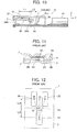
JP 2013-98088 A socket terminal 1 has three elongateconvex contact portions 2A to 2C formed on an inner facingcontact surface 2 and one dome-shaped embossedcontact 3A formed on aresilient contact piece 3 and aflat plug terminal 4 is sandwiched between the elongateconvex contact portions 2A to 2C and the dome-shaped embossedcontact 3A, as shown inFIG. 11 . - As shown in
FIG. 12 , the three elongateconvex contact portions 2A to 2C of thesocket terminal 1 are disposed on the inner facingcontact surface 2 so as to be located at three vertices of a triangle, and the dome-shaped embossedcontact 3A is located in a central portion of the triangle formed by the three elongateconvex contact portions 2A to 2C and at a substantially equal distance from any of the three elongateconvex contact portions 2A to 2C. - When the
plug terminal 4 is fitted with thesocket terminal 1, the elongateconvex contact portions 2A to 2C of thesocket terminal 1 come into contact with atop surface 4A of theplug terminal 4, while the dome-shaped embossedcontact 3A of thesocket terminal 1 comes into contact with abottom surface 4B of theplug terminal 4, whereby the electric connection is established between thesocket terminal 1 and theplug terminal 4. - In the connector terminal described in
JP 2013-98088 A FIGS. 11 and 12 , when thesocket terminal 1 and theplug terminal 4 are fitted with each other, the dome-shaped embossedcontact 3A formed on theresilient contact piece 3 of thesocket terminal 1 comes into contact with thebottom surface 4B of theplug terminal 4, so that theplug terminal 4 is elastically pressed against the inner facingcontact surface 2 of thesocket terminal 1, and accordingly, a load is exerted from thetop surface 4A of theplug terminal 4 to each of the three elongateconvex contact portions 2A to 2C formed on the inner facingcontact surface 2 of thesocket terminal 1. - When loads acting on the three elongate
convex contact portions 2A to 2C are unequal, the contact resistance between each of the elongateconvex contact portions 2A to 2C and thetop surface 4A of theplug terminal 4 varies, which may cause heat to be locally generated. - The present invention aims at removing the drawback described above and providing a connector terminal that can reduce the variance in contact resistance among a plurality of contact portions that make contact with a counter connector terminal in a flat plate shape, thereby preventing heat from being locally generated.
- A connector terminal according to the present invention is one that, when being fitted along a fitting axis with a counter connector terminal in a flat plate shape having a top surface and a bottom surface such that its contact points separately corresponding to the top surface and the bottom surface of the counter connector terminal come into contact with the top surface and the bottom surface, establishes an electric connection with the counter connector terminal, and the connector terminal comprises:
- one or more top side contact portions each of which makes contact with the top surface of the counter connector terminal; and
- three bottom side contact portions each of which is linear, extends along the fitting axis, and makes contact with the bottom surface of the counter connector terminal,
- wherein the three bottom side contact portions are arranged such that centers of the three bottom side contact portions form an isosceles triangle, and
- wherein the one or more top side contact portions are, when viewed in a direction perpendicular to the top surface of the counter connector terminal in a fitted state, positioned in a straight line that lies between a base of the isosceles triangle and a vertex of the isosceles triangle facing the base and extends parallel to the base in such a manner that a ratio of a distance from the base to a distance from the vertex is 1:2.
-
-
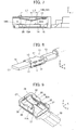
FIG. 1 is a perspective view showing a connector terminal according toEmbodiment 1 and a counter connector terminal in the non-fitted state. -
FIG. 2 is a perspective view showing a base member on which bottom side contact portions of the connector terminal according toEmbodiment 1 are formed. -
FIG. 3 is a perspective view showing a housing on which a top side contact portion of the connector terminal according toEmbodiment 1 is formed. -
FIG. 4 is a cutaway perspective view showing the inside of the housing used in the connector terminal according toEmbodiment 1. -
FIG. 5 is a cutaway perspective view showing an upper portion of the housing used in the connector terminal according toEmbodiment 1. -
FIG. 6 is a cutaway plan view showing the arrangement of the top side contact portion and bottom side contact portions of the connector terminal according toEmbodiment 1. -
FIG. 7 is a cutaway side view showing the internal structure of the connector terminal according toEmbodiment 1. -
FIG. 8 is a perspective view showing the connector terminal according toEmbodiment 1 and the counter connector terminal in the fitted state. -
FIG. 9 is a cutaway perspective view showing an upper portion of a connector terminal according toEmbodiment 2. -
FIG. 10 is a cutaway side view showing the internal structure of the connector terminal according toEmbodiment 2. -
FIG. 11 is a cross-sectional view schematically showing a conventional connector terminal in the fitted state. -
FIG. 12 is a plan view schematically showing the conventional connector terminal. - Embodiments of the present invention are described below based on the appended drawings.
- As shown in
FIG. 1 , aconnector terminal 11 according toEmbodiment 1 of the invention is a socket terminal including asocket portion 12 in a box shape having formed therein a counter connector terminal accommodating portion S, and acounter connector terminal 21 is a plug terminal in a flat plate shape. When thecounter connector terminal 21 is inserted into the counter connector terminal accommodating portion S of thesocket portion 12 of theconnector terminal 11 along a fitting axis C1, theconnector terminal 11 and thecounter connector terminal 21 are fitted with each other, thus establishing the electric connection. - The
connector terminal 11 includes an electricwire holding portion 13 that is formed at the back end of thesocket portion 12 along the fitting axis C1 to be integral with thesocket portion 12. - The
socket portion 12 includes abase member 14 integral with the electricwire holding portion 13 and ahousing 15 retaining thebase member 14 and covering the outer periphery of thebase member 14. Thebase member 14 and thehousing 15 are each made of a conductive material such as a metal. Thebase member 14 has a flat plate shape. - The
housing 15 includes abottom plate portion 16, aceiling portion 17 facing thebottom plate portion 16 in parallel therewith, and a pair oflateral wall portions 18 each of which connects either lateral end of thebottom plate portion 16 to the corresponding lateral end of theceiling portion 17. Thehousing 15 is thus in a box shape which is open at the front and back ends in the direction of the fitting axis C1. Thebase member 14 is fixed to a surface of thebottom plate portion 16 of thehousing 15 configured as above. - At the front end of the
socket portion 12 opposite from the end at which the electricwire holding portion 13 is located, the open front end of thehousing 15 constitutes aninsertion port 19 for receiving thecounter connector terminal 21. - For ease of understanding, a plane along which the
bottom plate portion 16 andceiling portion 17 of thehousing 15 extend is called "XY plane," a plane along which thelateral wall portions 18 extend "YZ plane," a direction in which the fitting axis C1 extends from thesocket portion 12 toward the electricwire holding portion 13 "+Y direction," and a direction from thebottom plate portion 16 of thehousing 15 toward theceiling portion 17 thereof "+Z direction." - The
counter connector terminal 21 is of a flat plate shape having a uniform thickness and extending along an XY plane. Thecounter connector terminal 21 includes atop surface 21A extending along the XY plane and facing in the +Z direction and abottom surface 21B extending along the XY plane in parallel with thetop surface 21A and facing in the -Z direction. - As shown in
FIG. 2 , three bottomside contact portions 14A to 14C are formed on a surface of thebase member 14 in a flat plate shape. The three bottomside contact portions 14A to 14C are linear contact portions projecting from the surface of thebase member 14 in the +Z direction and extending along the Y direction, that is, the fitting axis C1, and are non-spring contact portions that make contact with thebottom surface 21B of thecounter connector terminal 21 in the fitted state. The bottomside contact portions 14A to 14C are arranged to form an isosceles triangle T in an XY plane with the center of the bottomside contact portion 14A being set as a vertex A and a line segment connecting the centers of the remaining bottomside contact portions - The base BC of the isosceles triangle T extends in the X direction, and a median AM connecting a midpoint M of the base BC to the vertex A of the isosceles triangle T extends in the Y direction. The isosceles triangle T is symmetrical with respect to a YZ plane passing through the median AM. The median AM of the isosceles triangle T is positioned in the same YZ plane as the YZ plane passing through the fitting axis C1, and the three bottom
side contact portions 14A to 14C are arranged symmetrically with respect to the YZ plane passing through the fitting axis C1, i.e., a perpendicular plane that is perpendicular to thetop surface 21A of thecounter connector terminal 21 in the fitted state and passes through the fitting axis C1. - The structure of the
housing 15 is shown inFIG. 3 . A pair ofclaws 16A projecting in the +Z direction and being slightly bent toward the +Y direction are formed at the -Y direction-side end of thebottom plate portion 16 of thehousing 15, and a pair ofopenings 18A lying adjacent to thebottom plate portion 16 and opening along the Y direction are separately formed in the pair oflateral wall portions 18 of thehousing 15. The pair ofclaws 16A and the pair ofopenings 18A serve to retain thebase member 14 in thehousing 15. Thebase member 14 is fixed to the inside of thehousing 15 as shown inFIG. 1 with the -Y direction-side end of thebase member 14 being caught on the pair ofclaws 16A and both lateral edges of thebase member 14 being inserted in the pair ofopenings 18A. - A top
side contact portion 15A that makes contact with thetop surface 21A of thecounter connector terminal 21 in the fitted state is formed in thehousing 15. -
FIG. 4 is a drawing showing the inside of thehousing 15 with a +X direction-side half of theceiling portion 17 of thehousing 15 and, of the pair oflateral wall portions 18, a +X direction-sidelateral wall portion 18 being removed, andFIG. 5 is a drawing showing only a +Z direction-side portion of thehousing 15 with a -Z direction-side half of thehousing 15 being removed. As shown inFIG. 4 , a -Y direction-side end of theceiling portion 17 of thehousing 15 is so bent back inwardly as to extend in the +Y direction, thus forming aplate spring 20 with a V-shaped bent portion at its middle section in the Y direction that projects in the -Z direction. The topside contact portion 15A is formed of the bent portion of theplate spring 20 and, as shown inFIG. 5 , constitutes a linear spring contact portion extending over the entire width of theplate spring 20 in the X direction and facing in the -Z direction. - The
plate spring 20 is positioned symmetrically with respect to the YZ plane passing through the fitting axis C1 and has a symmetrical shape. The topside contact portion 15A formed of the bent portion of theplate spring 20 is also positioned symmetrically with respect to the YZ plane passing through the fitting axis C1, i.e., a perpendicular plane that is perpendicular to thetop surface 21A of thecounter connector terminal 21 in the fitted state and passes through the fitting axis C1, as well as having a symmetrical shape. - As shown in
FIG. 6 , when viewed in the Z direction, that is, a direction perpendicular to thetop surface 21A of thecounter connector terminal 21 in the fitted state, the topside contact portion 15A is positioned on a straight line SL that lies between the vertex A and the base BC of the isosceles triangle T, which is formed with the centers of the three bottomside contact portions 14A to 14C, and extends parallel to the base BC in such a manner that the ratio of a distance L2 from the base BC to a distance L1 from the vertex A is 1:2. -
FIG. 7 is a drawing showing the positional relationship between the topside contact portion 15A of thehousing 15 and the bottomside contact portions 14A to 14C of thebase member 14 fixed in thehousing 15 with the +X direction-side half of theceiling portion 17 of thehousing 15 and, of the pair oflateral wall portions 18, the +X direction-sidelateral wall portion 18 being removed similarly toFIG. 4 . The topside contact portion 15A and the bottomside contact portions 14A to 14C are arranged so that the distance L1 in the Y direction from the vertex A in the center of the bottomside contact portion 14A to the topside contact portion 15A is twice as long as the distance L2 in the Y direction from the base BC formed with the centers of the bottomside contact portions side contact portion 15A. - Next, the function of the
connector terminal 11 in a fitting process is described. As shown inFIG. 8 , when thecounter connector terminal 21 is inserted into the counter connector terminal accommodating portion S through theinsertion port 19 of thesocket portion 12 of theconnector terminal 11, theplate spring 20 of thehousing 15 is pressed by thecounter connector terminal 21 and thereby elastically deforms, and the topside contact portion 15A that is linear and extends in the X direction as shown inFIG. 5 comes into contact with thetop surface 21A of thecounter connector terminal 21, while the bottomside contact portions 14A to 14C that are arranged on thebase member 14, are linear, and extend in the Y direction as shown inFIG. 2 come into contact with thebottom surface 21B of thecounter connector terminal 21. - At this time, the insertion of the
counter connector terminal 21 causes theplate spring 20 to elastically deform, whereby a contact force N1 is exerted in the -Z direction from the topside contact portion 15A of thehousing 15 to thetop surface 21A of thecounter connector terminal 21. Since thecounter connector terminal 21 receives the contact force N1 from the topside contact portion 15A, a load acts on each of the three bottomside contact portions 14A to 14C through thebottom surface 21B of thecounter connector terminal 21 in the -Z direction. - As described above, the top
side contact portion 15A is positioned symmetrically with respect to the YZ plane passing through the fitting axis C1 and has a symmetrical shape, as well as being positioned on the straight line SL that lies between the vertex A and base BC of the isosceles triangle T, which is formed with the centers of the three bottomside contact portions 14A to 14C, and extends parallel to the base BC in such a manner that the ratio of the distance L2 from the base BC to the distance L1 from the vertex A is 1:2 when viewed in the Z direction. - Accordingly, assuming that the contact force N1 is exerted from the center of the top
side contact portion 15A extending in the X direction to thetop surface 21A of thecounter connector terminal 21 in a concentrated manner, the contact force N1 acts on a point that internally divides the median AM, which connects the midpoint M of the base BC to the vertex A of the isosceles triangle T, in such a manner that the distance L1 from the vertex A is twice as long as the distance L2 from the midpoint M (i.e., L1:L2 = 2:1). As a result, a load with a magnitude of N1/3 acts on the center of the bottomside contact portion 14A on the vertex A side of the isosceles triangle T, while loads with a magnitude of 2 x N1/3 in total act on the centers of the bottomside contact portions side contact portions side contact portions - Thus, loads are equally exerted from the
bottom surface 21B of thecounter connector terminal 21 to the three bottomside contact portions 14A to 14C, which can reduce the variance in contact resistance among the bottomside contact portions 14A to 14C that make contact with thebottom surface 21B of thecounter connector terminal 21 in a flat plate shape, thereby preventing heat from being locally generated. - In contrast, in the conventional connector terminal shown in
FIG. 12 , although the centers of the three elongateconvex contact portions 2A to 2C are arranged to form an isosceles triangle, a distance L3 from the center of the elongateconvex contact portion 2A at a vertex D of the isosceles triangle to the center G of the dome-shapedembossed contact 3A is substantially equal to a distance L4 from a midpoint H between the centers of the elongateconvex contact portions 2B and 2C at both ends of the base EF of the isosceles triangle to the center G of the dome-shapedembossed contact 3A. Therefore, when a contact force N2 is exerted from the center G of the dome-shapedembossed contact 3A to the plug terminal, a load with a magnitude of N2/2 acts on the center of the elongateconvex contact portion 2A at the vertex D, while a load with a magnitude of N2/4 acts on each of the centers of the elongateconvex contact portions 2B and 2C at both ends of the base EF. Thus, loads unequally act on the three elongateconvex contact portions 2A to 2C, whereby the contact resistance of each of the elongateconvex contact portions 2A to 2C varies, which may cause heat to be locally generated. - While in
Embodiment 1 above, thehousing 15 has the topside contact portion 15A extending over the entire width of theplate spring 20 in the X direction, the invention is not limited thereto. For example, as in aconnector terminal 31 shown inFIGS. 9 and10 , a pair of topside contact portions 35A may be disposed at the same distance in the +X and -X directions from the YZ plane passing through the fitting axis C1. Those topside contact portions 35A are arranged symmetrically with respect to the YZ plane passing through the fitting axis C1 and have a symmetrical shape. - The
connector terminal 31 includes asocket portion 32 and an electricwire holding portion 33 integral with thesocket portion 32. Thesocket portion 32 includes abottom plate portion 34, aceiling portion 35 facing thebottom plate portion 34 in parallel therewith, and a pair oflateral wall portions 36 each of which connects either lateral end of thebottom plate portion 34 to the corresponding lateral end of theceiling portion 35. - The
ceiling portion 35 is divided at its center portion along the fitting axis C1 into twoupper plate portions 37, and a pair ofspring portions 38 having a cantilever shape are formed which is bent at the -Y direction-side end of theupper plate portions 37 toward the inside of thesocket portion 32 and extend in the +Y direction. The topside contact portions 35A are separately disposed at the tip ends of thespring portions 38. The pair ofspring portions 38 are the same in size and spring constant. - Three bottom
side contact portions 34A to 34C are formed on thebottom plate portion 34 of thesocket member 32. As with the bottomside contact portions 14A to 14C inEmbodiment 1, the bottomside contact portions 34A to 34C are linear and non-spring contact portions projecting from a surface of thebottom plate portion 34 in the +Z direction and extending along the Y direction, that is, the fitting axis C1, and are arranged to form an isosceles triangle in an XY plane with the center of the bottomside contact portion 34A being set as a vertex A and a line segment connecting the centers of the remaining bottomside contact portions - The pair of top
side contact portions 35A are, when viewed in the Z direction, positioned on a straight line that lies between the vertex A and base BC of the isosceles triangle, which is formed with the centers of the three bottomside contact portions 34A to 34C, and extends parallel to the base BC in such a manner that the ratio of a distance L2 from the base BC to a distance L1 from the vertex A is 1:2. - While in
Embodiment 1 above, thehousing 15 having the topside contact portion 15A and thebase member 14 having the three bottomside contact portions 14A to 14C are separate components, in theconnector terminal 31 ofEmbodiment 2 shown inFIGS. 9 and10 , the pair of topside contact portions 35A and the three bottomside contact portions 34A to 34C are disposed at thesocket portion 32 formed as a single component. - In a fitting process, the insertion of the
counter connector terminal 21 causes the pair ofspring portions 38 to elastically deform, whereby contact forces of the same magnitude are exerted in the -Z direction from both topside contact portions 35A to thetop surface 21A of thecounter connector terminal 21, and the resultant force of the two contact forces acts on the middle position between the pair of topside contact portions 35A, i.e., near the fitting axis C1 in the X direction. Therefore, loads are equally exerted to the three bottomside contact portions 34A to 34C, which can reduce the variance in contact resistance, thereby preventing heat from being locally generated. - In addition, since the pair of top
side contact portions 35A are disposed at the same distance in the +X and -X directions from the YZ plane passing through the fitting axis C1, when a moment in the XY plane acts on thecounter connector terminal 21 fitted with theconnector terminal 31, a frictional force is exerted from each of the pair of topside contact portions 35A, which is effective at minimizing displacement of thecounter connector terminal 21 in a rotational direction in the XY plane. - Also when a moment about the fitting axis C1 acts on the
counter connector terminal 21 fitted with theconnector terminal 31, in addition to contact forces exerted from the pair of topside contact portions 35A to thecounter connector terminal 21 upon fitting of thecounter connector terminal 21, a normal force having a magnitude corresponding to the moment is generated from one of the topside contact portions 35A to thecounter connector terminal 21, so that the displacement of thecounter connector terminal 21 in a rotational direction in the XZ plane can be minimized. - With a longer distance between the YZ plane passing through the fitting axis C1 and each of the top
side contact portions 35A, the configuration more effectively works against a moment exerted to thecounter connector terminal 21, thereby minimizing displacement of thecounter connector terminal 21 in a rotational direction. - It should be noted that three or more top side contact portions may be provided as long as they are, when viewed in the Z direction, positioned on the straight line that lies between the vertex A and base BC of the isosceles triangle, which is formed with the centers of the three bottom
side contact portions 34A to 34C, and extends parallel to the base BC in such a manner that the ratio of the distance L2 from the base BC to the distance L1 from the vertex A is 1:2. Even when, for instance, an external force acts due to vibration or other factors, the provision of two or more top side contact portions serves to minimize displacement of thecounter connector terminal 21 relative to theconnector terminal 11 whereby the top and bottom side contact portions are prevented from being worn away. - In addition, even with merely a single top side contact portion which is positioned on the straight line that lies between the vertex A and base BC of the isosceles triangle to be parallel to the base BC in such a manner that the ratio of the distance L2 from the base BC to the distance L1 from the vertex A is 1:2 and also positioned in the YZ plane passing through the fitting axis C1, it is possible to reduce the variance in contact resistance by equalizing loads exerted to the three bottom
side contact portions 34A to 34C, thereby preventing heat from being locally generated. - For
Embodiment 1 above, the configuration may also be employed in which thebase member 14 and thehousing 15 are integral with each other and the topside contact portion 15A and the three bottomside contact portions 14A to 14C are disposed at thesocket portion 12 which is a single component. - Aside from that, while the three bottom
side contact portions 14A to 14C inEmbodiment 1 and the three bottomside contact portions 34A to 34C inEmbodiment 2 are constituted of non-spring contact portions, thecontact portions 14A to 14C and 34A to 34C may be spring contact portions as with the topside contact portions
Claims (7)
- A connector terminal that, when being fitted along a fitting axis (C1) with a counter connector terminal (21) in a flat plate shape having a top surface (21A) and a bottom surface (21B) such that its contact points separately corresponding to the top surface and the bottom surface of the counter connector terminal come into contact with the top surface and the bottom surface, establishes an electric connection with the counter connector terminal, the connector terminal comprising:one or more top side contact portions (15A, 35A) each of which makes contact with the top surface of the counter connector terminal; andthree bottom side contact portions (14A to 14C, 34A to 34C) each of which is linear, extends along the fitting axis, and makes contact with the bottom surface of the counter connector terminal,wherein the three bottom side contact portions are arranged such that centers of the three bottom side contact portions form an isosceles triangle (T), andwherein the one or more top side contact portions (15A, 35A) are, when viewed in a direction perpendicular to the top surface (21A) of the counter connector terminal (21) in a fitted state, positioned in a straight line that lies between a base of the isosceles triangle and a vertex (A) of the isosceles triangle facing the base and extends parallel to the base in such a manner that a ratio of a distance (L2) from the base to a distance (L1) from the vertex is 1:2.
- The connector terminal according to claim 1, wherein the one or more top side contact portions (15A, 35A) are each constituted of a linear contact portion extending in parallel with the straight line.
- The connector terminal according to claim 1,
wherein the one or more top side contact portions (15A, 35A) are positioned symmetrically with respect to a perpendicular plane which is perpendicular to the top surface (21A) of the counter connector terminal (21) in the fitted state and passes through the fitting axis (C1), and
wherein the three bottom side contact portions (14A to 14C, 34A to 34C) are arranged symmetrically with respect to the perpendicular plane. - The connector terminal according to claim 3,
wherein the one or more top side contact portions (15A, 35A) are each constituted of a spring contact portion, and
wherein the three bottom side contact portions (14A to 14C, 34A to 34C) are each constituted of a non-spring contact portion. - The connector terminal according to claim 4, wherein the spring contact portion has a symmetrical shape with respect to a plane being parallel to the perpendicular plane and passing through the spring contact portion.
- The connector terminal according to claim 3, wherein the one or more top side contact portions (15A, 35A) are each constituted of a bent portion of a bent plate spring.
- The connector terminal according to claim 1, wherein the one or more top side contact portions (15A) comprise a single contact portion.
Applications Claiming Priority (1)
| Application Number | Priority Date | Filing Date | Title |
|---|---|---|---|
| JP2016085466A JP6591341B2 (en) | 2016-04-21 | 2016-04-21 | Connector terminal |
Publications (2)
| Publication Number | Publication Date |
|---|---|
| EP3236534A1 true EP3236534A1 (en) | 2017-10-25 |
| EP3236534B1 EP3236534B1 (en) | 2018-07-18 |
Family
ID=58098544
Family Applications (1)
| Application Number | Title | Priority Date | Filing Date |
|---|---|---|---|
| EP17157056.7A Active EP3236534B1 (en) | 2016-04-21 | 2017-02-21 | Connector terminal |
Country Status (4)
| Country | Link |
|---|---|
| US (1) | US9837745B2 (en) |
| EP (1) | EP3236534B1 (en) |
| JP (1) | JP6591341B2 (en) |
| CN (1) | CN107305982B (en) |
Cited By (1)
| Publication number | Priority date | Publication date | Assignee | Title |
|---|---|---|---|---|
| CN114465055A (en) * | 2022-03-18 | 2022-05-10 | 安徽江淮汽车集团股份有限公司 | Automobile socket terminal structure |
Families Citing this family (17)
| Publication number | Priority date | Publication date | Assignee | Title |
|---|---|---|---|---|
| JP6607141B2 (en) * | 2016-05-12 | 2019-11-20 | 住友電装株式会社 | Terminal |
| JP6776050B2 (en) * | 2016-08-01 | 2020-10-28 | 日本航空電子工業株式会社 | Female terminal and connector with it |
| DE102016221351A1 (en) * | 2016-10-28 | 2018-05-03 | Te Connectivity Germany Gmbh | Flat contact socket with extension arm |
| JP6787175B2 (en) * | 2017-02-22 | 2020-11-18 | 株式会社オートネットワーク技術研究所 | Multi-contact terminal |
| JP6988921B2 (en) * | 2018-01-16 | 2022-01-05 | 株式会社オートネットワーク技術研究所 | Terminal |
| DE102018214203A1 (en) * | 2018-08-22 | 2020-02-27 | Te Connectivity Germany Gmbh | Contact configuration |
| JP2020043002A (en) * | 2018-09-12 | 2020-03-19 | 株式会社オートネットワーク技術研究所 | Connection terminal and connector |
| JP7052665B2 (en) * | 2018-10-02 | 2022-04-12 | 株式会社オートネットワーク技術研究所 | Female terminal |
| US12320042B2 (en) | 2019-09-04 | 2025-06-03 | Milliken & Company | Flame-resistant fabric |
| CN113131239B (en) | 2019-12-31 | 2023-08-15 | 富鼎精密工业(郑州)有限公司 | electrical connector |
| CN113131240B (en) * | 2019-12-31 | 2024-05-17 | 富鼎精密工业(郑州)有限公司 | Electric connector |
| US12413016B2 (en) | 2020-11-12 | 2025-09-09 | Autonetworks Technologies, Ltd. | Connector and connector device |
| JP7548161B2 (en) * | 2020-11-12 | 2024-09-10 | 株式会社オートネットワーク技術研究所 | Connector and connector device |
| US11761124B1 (en) | 2021-09-09 | 2023-09-19 | Milliken & Company | Elastic flame-resistant fabric |
| DE102023101116A1 (en) * | 2023-01-18 | 2024-07-18 | Te Connectivity Solutions Gmbh | Vibration-resistant electrical flat socket terminal |
| JP2024123903A (en) * | 2023-03-02 | 2024-09-12 | 日本航空電子工業株式会社 | connector |
| WO2025233318A1 (en) * | 2024-05-07 | 2025-11-13 | Robert Bosch Gmbh | Plug connector assembly |
Citations (3)
| Publication number | Priority date | Publication date | Assignee | Title |
|---|---|---|---|---|
| US20100197177A1 (en) * | 2008-08-04 | 2010-08-05 | Tyco Electronics Corporation | Socket contact |
| WO2011125727A1 (en) * | 2010-03-31 | 2011-10-13 | 古河電気工業株式会社 | Female terminal |
| US20130109250A1 (en) * | 2011-11-02 | 2013-05-02 | Sumitomo Wiring Systems, Ltd. | Female terminal fitting |
Family Cites Families (13)
| Publication number | Priority date | Publication date | Assignee | Title |
|---|---|---|---|---|
| US3142891A (en) * | 1961-04-18 | 1964-08-04 | Elco Corp | Method of forming rigid contact tails |
| DE3014706C2 (en) * | 1980-04-17 | 1982-06-24 | C.A. Weidmüller KG, 4930 Detmold | Electrical connector assembly |
| JPS61237375A (en) * | 1985-04-11 | 1986-10-22 | アンプ インコ−ポレ−テツド | Receptacle terminal |
| JPH0348857Y2 (en) * | 1989-01-24 | 1991-10-18 | ||
| GB9411287D0 (en) * | 1994-06-06 | 1994-07-27 | Amp Gmbh | High current receptacle terminal |
| JP2003331968A (en) * | 2002-05-13 | 2003-11-21 | Sumitomo Wiring Syst Ltd | Female terminal fitting |
| US20100029146A1 (en) * | 2008-08-04 | 2010-02-04 | Tyco Electronics Corporation | Socket contact |
| JP5560851B2 (en) | 2010-03-31 | 2014-07-30 | 株式会社アドヴィックス | Brake device for vehicle |
| JP2012079505A (en) * | 2010-09-30 | 2012-04-19 | Japan Aviation Electronics Industry Ltd | Connector assembly |
| JP2013229222A (en) * | 2012-04-26 | 2013-11-07 | Sumitomo Wiring Syst Ltd | Terminal fitting |
| JP2014082158A (en) * | 2012-10-18 | 2014-05-08 | Sumitomo Wiring Syst Ltd | Terminal fitting |
| KR101608375B1 (en) * | 2014-12-11 | 2016-04-01 | 주식회사 유라코퍼레이션 | Female terminal having bead part |
| JP6619287B2 (en) * | 2016-04-14 | 2019-12-11 | 日本航空電子工業株式会社 | Connector terminal |
-
2016
- 2016-04-21 JP JP2016085466A patent/JP6591341B2/en active Active
-
2017
- 2017-02-09 US US15/428,670 patent/US9837745B2/en active Active
- 2017-02-21 EP EP17157056.7A patent/EP3236534B1/en active Active
- 2017-03-14 CN CN201710151730.5A patent/CN107305982B/en active Active
Patent Citations (4)
| Publication number | Priority date | Publication date | Assignee | Title |
|---|---|---|---|---|
| US20100197177A1 (en) * | 2008-08-04 | 2010-08-05 | Tyco Electronics Corporation | Socket contact |
| WO2011125727A1 (en) * | 2010-03-31 | 2011-10-13 | 古河電気工業株式会社 | Female terminal |
| US20130109250A1 (en) * | 2011-11-02 | 2013-05-02 | Sumitomo Wiring Systems, Ltd. | Female terminal fitting |
| JP2013098088A (en) | 2011-11-02 | 2013-05-20 | Sumitomo Wiring Syst Ltd | Female type terminal fitting |
Cited By (1)
| Publication number | Priority date | Publication date | Assignee | Title |
|---|---|---|---|---|
| CN114465055A (en) * | 2022-03-18 | 2022-05-10 | 安徽江淮汽车集团股份有限公司 | Automobile socket terminal structure |
Also Published As
| Publication number | Publication date |
|---|---|
| CN107305982A (en) | 2017-10-31 |
| US9837745B2 (en) | 2017-12-05 |
| CN107305982B (en) | 2019-05-07 |
| JP2017195114A (en) | 2017-10-26 |
| US20170310032A1 (en) | 2017-10-26 |
| EP3236534B1 (en) | 2018-07-18 |
| JP6591341B2 (en) | 2019-10-16 |
Similar Documents
| Publication | Publication Date | Title |
|---|---|---|
| EP3236534B1 (en) | Connector terminal | |
| EP3232514B1 (en) | Connector terminal | |
| EP3249752B1 (en) | Connecting structure | |
| US10164366B2 (en) | Connector terminal and electric connector | |
| US20140170886A1 (en) | Electrical connector assembled component | |
| JP6227225B2 (en) | connector | |
| US10283907B2 (en) | Floating connector and electronic device module | |
| US20190245293A1 (en) | Terminal module and connector | |
| US10784491B2 (en) | Battery terminal | |
| JP2017134933A (en) | Terminal connection structure | |
| EP2750253A1 (en) | Connector | |
| EP2862238B1 (en) | Connector terminal | |
| US20240313454A1 (en) | Terminal unit, female terminal and male terminal | |
| JP6681655B2 (en) | Coaxial connector | |
| JP2013182879A (en) | Electronic component connection structure | |
| US10333240B2 (en) | Connector assembly for electrically connecting circuit boards | |
| KR20110115238A (en) | terminal | |
| KR20170117693A (en) | Connector | |
| US20150111439A1 (en) | Joint terminal | |
| JP2017010867A (en) | Male terminal |
Legal Events
| Date | Code | Title | Description |
|---|---|---|---|
| PUAI | Public reference made under article 153(3) epc to a published international application that has entered the european phase |
Free format text: ORIGINAL CODE: 0009012 |
|
| STAA | Information on the status of an ep patent application or granted ep patent |
Free format text: STATUS: REQUEST FOR EXAMINATION WAS MADE |
|
| 17P | Request for examination filed |
Effective date: 20170221 |
|
| AK | Designated contracting states |
Kind code of ref document: A1 Designated state(s): AL AT BE BG CH CY CZ DE DK EE ES FI FR GB GR HR HU IE IS IT LI LT LU LV MC MK MT NL NO PL PT RO RS SE SI SK SM TR |
|
| AX | Request for extension of the european patent |
Extension state: BA ME |
|
| RBV | Designated contracting states (corrected) |
Designated state(s): AL AT BE BG CH CY CZ DE DK EE ES FI FR GB GR HR HU IE IS IT LI LT LU LV MC MK MT NL NO PL PT RO RS SE SI SK SM TR |
|
| GRAP | Despatch of communication of intention to grant a patent |
Free format text: ORIGINAL CODE: EPIDOSNIGR1 |
|
| STAA | Information on the status of an ep patent application or granted ep patent |
Free format text: STATUS: GRANT OF PATENT IS INTENDED |
|
| RIC1 | Information provided on ipc code assigned before grant |
Ipc: H01R 13/11 20060101AFI20180118BHEP Ipc: H01R 13/15 20060101ALI20180118BHEP Ipc: H01R 13/24 20060101ALN20180118BHEP |
|
| INTG | Intention to grant announced |
Effective date: 20180206 |
|
| GRAS | Grant fee paid |
Free format text: ORIGINAL CODE: EPIDOSNIGR3 |
|
| GRAA | (expected) grant |
Free format text: ORIGINAL CODE: 0009210 |
|
| STAA | Information on the status of an ep patent application or granted ep patent |
Free format text: STATUS: THE PATENT HAS BEEN GRANTED |
|
| AK | Designated contracting states |
Kind code of ref document: B1 Designated state(s): AL AT BE BG CH CY CZ DE DK EE ES FI FR GB GR HR HU IE IS IT LI LT LU LV MC MK MT NL NO PL PT RO RS SE SI SK SM TR |
|
| REG | Reference to a national code |
Ref country code: GB Ref legal event code: FG4D |
|
| REG | Reference to a national code |
Ref country code: CH Ref legal event code: EP |
|
| REG | Reference to a national code |
Ref country code: IE Ref legal event code: FG4D |
|
| REG | Reference to a national code |
Ref country code: AT Ref legal event code: REF Ref document number: 1020363 Country of ref document: AT Kind code of ref document: T Effective date: 20180815 |
|
| REG | Reference to a national code |
Ref country code: DE Ref legal event code: R096 Ref document number: 602017000158 Country of ref document: DE |
|
| REG | Reference to a national code |
Ref country code: NL Ref legal event code: MP Effective date: 20180718 |
|
| REG | Reference to a national code |
Ref country code: LT Ref legal event code: MG4D |
|
| REG | Reference to a national code |
Ref country code: AT Ref legal event code: MK05 Ref document number: 1020363 Country of ref document: AT Kind code of ref document: T Effective date: 20180718 |
|
| PG25 | Lapsed in a contracting state [announced via postgrant information from national office to epo] |
Ref country code: NL Free format text: LAPSE BECAUSE OF FAILURE TO SUBMIT A TRANSLATION OF THE DESCRIPTION OR TO PAY THE FEE WITHIN THE PRESCRIBED TIME-LIMIT Effective date: 20180718 |
|
| PG25 | Lapsed in a contracting state [announced via postgrant information from national office to epo] |
Ref country code: LT Free format text: LAPSE BECAUSE OF FAILURE TO SUBMIT A TRANSLATION OF THE DESCRIPTION OR TO PAY THE FEE WITHIN THE PRESCRIBED TIME-LIMIT Effective date: 20180718 Ref country code: SE Free format text: LAPSE BECAUSE OF FAILURE TO SUBMIT A TRANSLATION OF THE DESCRIPTION OR TO PAY THE FEE WITHIN THE PRESCRIBED TIME-LIMIT Effective date: 20180718 Ref country code: BG Free format text: LAPSE BECAUSE OF FAILURE TO SUBMIT A TRANSLATION OF THE DESCRIPTION OR TO PAY THE FEE WITHIN THE PRESCRIBED TIME-LIMIT Effective date: 20181018 Ref country code: AT Free format text: LAPSE BECAUSE OF FAILURE TO SUBMIT A TRANSLATION OF THE DESCRIPTION OR TO PAY THE FEE WITHIN THE PRESCRIBED TIME-LIMIT Effective date: 20180718 Ref country code: FI Free format text: LAPSE BECAUSE OF FAILURE TO SUBMIT A TRANSLATION OF THE DESCRIPTION OR TO PAY THE FEE WITHIN THE PRESCRIBED TIME-LIMIT Effective date: 20180718 Ref country code: IS Free format text: LAPSE BECAUSE OF FAILURE TO SUBMIT A TRANSLATION OF THE DESCRIPTION OR TO PAY THE FEE WITHIN THE PRESCRIBED TIME-LIMIT Effective date: 20181118 Ref country code: RS Free format text: LAPSE BECAUSE OF FAILURE TO SUBMIT A TRANSLATION OF THE DESCRIPTION OR TO PAY THE FEE WITHIN THE PRESCRIBED TIME-LIMIT Effective date: 20180718 Ref country code: PL Free format text: LAPSE BECAUSE OF FAILURE TO SUBMIT A TRANSLATION OF THE DESCRIPTION OR TO PAY THE FEE WITHIN THE PRESCRIBED TIME-LIMIT Effective date: 20180718 Ref country code: NO Free format text: LAPSE BECAUSE OF FAILURE TO SUBMIT A TRANSLATION OF THE DESCRIPTION OR TO PAY THE FEE WITHIN THE PRESCRIBED TIME-LIMIT Effective date: 20181018 Ref country code: GR Free format text: LAPSE BECAUSE OF FAILURE TO SUBMIT A TRANSLATION OF THE DESCRIPTION OR TO PAY THE FEE WITHIN THE PRESCRIBED TIME-LIMIT Effective date: 20181019 |
|
| PG25 | Lapsed in a contracting state [announced via postgrant information from national office to epo] |
Ref country code: LV Free format text: LAPSE BECAUSE OF FAILURE TO SUBMIT A TRANSLATION OF THE DESCRIPTION OR TO PAY THE FEE WITHIN THE PRESCRIBED TIME-LIMIT Effective date: 20180718 Ref country code: HR Free format text: LAPSE BECAUSE OF FAILURE TO SUBMIT A TRANSLATION OF THE DESCRIPTION OR TO PAY THE FEE WITHIN THE PRESCRIBED TIME-LIMIT Effective date: 20180718 Ref country code: AL Free format text: LAPSE BECAUSE OF FAILURE TO SUBMIT A TRANSLATION OF THE DESCRIPTION OR TO PAY THE FEE WITHIN THE PRESCRIBED TIME-LIMIT Effective date: 20180718 |
|
| REG | Reference to a national code |
Ref country code: DE Ref legal event code: R097 Ref document number: 602017000158 Country of ref document: DE |
|
| PG25 | Lapsed in a contracting state [announced via postgrant information from national office to epo] |
Ref country code: ES Free format text: LAPSE BECAUSE OF FAILURE TO SUBMIT A TRANSLATION OF THE DESCRIPTION OR TO PAY THE FEE WITHIN THE PRESCRIBED TIME-LIMIT Effective date: 20180718 Ref country code: RO Free format text: LAPSE BECAUSE OF FAILURE TO SUBMIT A TRANSLATION OF THE DESCRIPTION OR TO PAY THE FEE WITHIN THE PRESCRIBED TIME-LIMIT Effective date: 20180718 Ref country code: CZ Free format text: LAPSE BECAUSE OF FAILURE TO SUBMIT A TRANSLATION OF THE DESCRIPTION OR TO PAY THE FEE WITHIN THE PRESCRIBED TIME-LIMIT Effective date: 20180718 Ref country code: IT Free format text: LAPSE BECAUSE OF FAILURE TO SUBMIT A TRANSLATION OF THE DESCRIPTION OR TO PAY THE FEE WITHIN THE PRESCRIBED TIME-LIMIT Effective date: 20180718 Ref country code: EE Free format text: LAPSE BECAUSE OF FAILURE TO SUBMIT A TRANSLATION OF THE DESCRIPTION OR TO PAY THE FEE WITHIN THE PRESCRIBED TIME-LIMIT Effective date: 20180718 |
|
| PLBE | No opposition filed within time limit |
Free format text: ORIGINAL CODE: 0009261 |
|
| STAA | Information on the status of an ep patent application or granted ep patent |
Free format text: STATUS: NO OPPOSITION FILED WITHIN TIME LIMIT |
|
| PG25 | Lapsed in a contracting state [announced via postgrant information from national office to epo] |
Ref country code: SK Free format text: LAPSE BECAUSE OF FAILURE TO SUBMIT A TRANSLATION OF THE DESCRIPTION OR TO PAY THE FEE WITHIN THE PRESCRIBED TIME-LIMIT Effective date: 20180718 Ref country code: DK Free format text: LAPSE BECAUSE OF FAILURE TO SUBMIT A TRANSLATION OF THE DESCRIPTION OR TO PAY THE FEE WITHIN THE PRESCRIBED TIME-LIMIT Effective date: 20180718 Ref country code: SM Free format text: LAPSE BECAUSE OF FAILURE TO SUBMIT A TRANSLATION OF THE DESCRIPTION OR TO PAY THE FEE WITHIN THE PRESCRIBED TIME-LIMIT Effective date: 20180718 |
|
| 26N | No opposition filed |
Effective date: 20190423 |
|
| PG25 | Lapsed in a contracting state [announced via postgrant information from national office to epo] |
Ref country code: SI Free format text: LAPSE BECAUSE OF FAILURE TO SUBMIT A TRANSLATION OF THE DESCRIPTION OR TO PAY THE FEE WITHIN THE PRESCRIBED TIME-LIMIT Effective date: 20180718 |
|
| PG25 | Lapsed in a contracting state [announced via postgrant information from national office to epo] |
Ref country code: MC Free format text: LAPSE BECAUSE OF FAILURE TO SUBMIT A TRANSLATION OF THE DESCRIPTION OR TO PAY THE FEE WITHIN THE PRESCRIBED TIME-LIMIT Effective date: 20180718 Ref country code: LU Free format text: LAPSE BECAUSE OF NON-PAYMENT OF DUE FEES Effective date: 20190221 |
|
| REG | Reference to a national code |
Ref country code: BE Ref legal event code: MM Effective date: 20190228 |
|
| REG | Reference to a national code |
Ref country code: IE Ref legal event code: MM4A |
|
| PG25 | Lapsed in a contracting state [announced via postgrant information from national office to epo] |
Ref country code: IE Free format text: LAPSE BECAUSE OF NON-PAYMENT OF DUE FEES Effective date: 20190221 |
|
| PG25 | Lapsed in a contracting state [announced via postgrant information from national office to epo] |
Ref country code: BE Free format text: LAPSE BECAUSE OF NON-PAYMENT OF DUE FEES Effective date: 20190228 |
|
| PG25 | Lapsed in a contracting state [announced via postgrant information from national office to epo] |
Ref country code: TR Free format text: LAPSE BECAUSE OF FAILURE TO SUBMIT A TRANSLATION OF THE DESCRIPTION OR TO PAY THE FEE WITHIN THE PRESCRIBED TIME-LIMIT Effective date: 20180718 |
|
| PG25 | Lapsed in a contracting state [announced via postgrant information from national office to epo] |
Ref country code: PT Free format text: LAPSE BECAUSE OF FAILURE TO SUBMIT A TRANSLATION OF THE DESCRIPTION OR TO PAY THE FEE WITHIN THE PRESCRIBED TIME-LIMIT Effective date: 20181118 Ref country code: MT Free format text: LAPSE BECAUSE OF NON-PAYMENT OF DUE FEES Effective date: 20190221 |
|
| REG | Reference to a national code |
Ref country code: CH Ref legal event code: PL |
|
| PG25 | Lapsed in a contracting state [announced via postgrant information from national office to epo] |
Ref country code: LI Free format text: LAPSE BECAUSE OF NON-PAYMENT OF DUE FEES Effective date: 20200229 Ref country code: CH Free format text: LAPSE BECAUSE OF NON-PAYMENT OF DUE FEES Effective date: 20200229 |
|
| PG25 | Lapsed in a contracting state [announced via postgrant information from national office to epo] |
Ref country code: CY Free format text: LAPSE BECAUSE OF FAILURE TO SUBMIT A TRANSLATION OF THE DESCRIPTION OR TO PAY THE FEE WITHIN THE PRESCRIBED TIME-LIMIT Effective date: 20180718 |
|
| PG25 | Lapsed in a contracting state [announced via postgrant information from national office to epo] |
Ref country code: HU Free format text: LAPSE BECAUSE OF FAILURE TO SUBMIT A TRANSLATION OF THE DESCRIPTION OR TO PAY THE FEE WITHIN THE PRESCRIBED TIME-LIMIT; INVALID AB INITIO Effective date: 20170221 |
|
| PG25 | Lapsed in a contracting state [announced via postgrant information from national office to epo] |
Ref country code: MK Free format text: LAPSE BECAUSE OF FAILURE TO SUBMIT A TRANSLATION OF THE DESCRIPTION OR TO PAY THE FEE WITHIN THE PRESCRIBED TIME-LIMIT Effective date: 20180718 |
|
| PGFP | Annual fee paid to national office [announced via postgrant information from national office to epo] |
Ref country code: FR Payment date: 20251231 Year of fee payment: 10 |
|
| PGFP | Annual fee paid to national office [announced via postgrant information from national office to epo] |
Ref country code: GB Payment date: 20260106 Year of fee payment: 10 |
|
| PGFP | Annual fee paid to national office [announced via postgrant information from national office to epo] |
Ref country code: DE Payment date: 20251230 Year of fee payment: 10 |