EP3236532A1 - Dynamically allocated broad band multi-tap antenna - Google Patents
Dynamically allocated broad band multi-tap antenna Download PDFInfo
- Publication number
- EP3236532A1 EP3236532A1 EP17155543.6A EP17155543A EP3236532A1 EP 3236532 A1 EP3236532 A1 EP 3236532A1 EP 17155543 A EP17155543 A EP 17155543A EP 3236532 A1 EP3236532 A1 EP 3236532A1
- Authority
- EP
- European Patent Office
- Prior art keywords
- antenna
- conductors
- taps
- combiners
- signals
- Prior art date
- Legal status (The legal status is an assumption and is not a legal conclusion. Google has not performed a legal analysis and makes no representation as to the accuracy of the status listed.)
- Granted
Links
Images

Classifications
-
- H—ELECTRICITY
- H01—ELECTRIC ELEMENTS
- H01Q—ANTENNAS, i.e. RADIO AERIALS
- H01Q1/00—Details of, or arrangements associated with, antennas
- H01Q1/36—Structural form of radiating elements, e.g. cone, spiral, umbrella; Particular materials used therewith
-
- H—ELECTRICITY
- H01—ELECTRIC ELEMENTS
- H01Q—ANTENNAS, i.e. RADIO AERIALS
- H01Q5/00—Arrangements for simultaneous operation of antennas on two or more different wavebands, e.g. dual-band or multi-band arrangements
- H01Q5/50—Feeding or matching arrangements for broad-band or multi-band operation
-
- H—ELECTRICITY
- H01—ELECTRIC ELEMENTS
- H01P—WAVEGUIDES; RESONATORS, LINES, OR OTHER DEVICES OF THE WAVEGUIDE TYPE
- H01P5/00—Coupling devices of the waveguide type
- H01P5/12—Coupling devices having more than two ports
- H01P5/16—Conjugate devices, i.e. devices having at least one port decoupled from one other port
-
- H—ELECTRICITY
- H01—ELECTRIC ELEMENTS
- H01Q—ANTENNAS, i.e. RADIO AERIALS
- H01Q1/00—Details of, or arrangements associated with, antennas
- H01Q1/50—Structural association of antennas with earthing switches, lead-in devices or lightning protectors
-
- H—ELECTRICITY
- H01—ELECTRIC ELEMENTS
- H01Q—ANTENNAS, i.e. RADIO AERIALS
- H01Q21/00—Antenna arrays or systems
- H01Q21/0006—Particular feeding systems
-
- H—ELECTRICITY
- H01—ELECTRIC ELEMENTS
- H01Q—ANTENNAS, i.e. RADIO AERIALS
- H01Q21/00—Antenna arrays or systems
- H01Q21/06—Arrays of individually energised antenna units similarly polarised and spaced apart
- H01Q21/08—Arrays of individually energised antenna units similarly polarised and spaced apart the units being spaced along or adjacent to a rectilinear path
-
- H—ELECTRICITY
- H01—ELECTRIC ELEMENTS
- H01Q—ANTENNAS, i.e. RADIO AERIALS
- H01Q3/00—Arrangements for changing or varying the orientation or the shape of the directional pattern of the waves radiated from an antenna or antenna system
- H01Q3/24—Arrangements for changing or varying the orientation or the shape of the directional pattern of the waves radiated from an antenna or antenna system varying the orientation by switching energy from one active radiating element to another, e.g. for beam switching
-
- H—ELECTRICITY
- H01—ELECTRIC ELEMENTS
- H01Q—ANTENNAS, i.e. RADIO AERIALS
- H01Q5/00—Arrangements for simultaneous operation of antennas on two or more different wavebands, e.g. dual-band or multi-band arrangements
- H01Q5/30—Arrangements for providing operation on different wavebands
- H01Q5/307—Individual or coupled radiating elements, each element being fed in an unspecified way
- H01Q5/314—Individual or coupled radiating elements, each element being fed in an unspecified way using frequency dependent circuits or components, e.g. trap circuits or capacitors
- H01Q5/335—Individual or coupled radiating elements, each element being fed in an unspecified way using frequency dependent circuits or components, e.g. trap circuits or capacitors at the feed, e.g. for impedance matching
Definitions
- the invention is related generally to the field of antennas, and more particularly, to a dynamically allocated broadband multi-tap antenna.
- Antennas are used in many different systems and applications, such as communications, global positioning, radar, transponders, and other systems and applications.
- antennas may be used on aircraft or other vehicles to provide for these and other functions.
- physical space on vehicles is limited. Therefore, it is desirable to have an antenna that is as small as possible.
- Antenna size is defined here in terms of wavelengths.
- a small antenna is defined as one that is a fraction of a wavelength in size. One way to make an antenna small is to sacrifice bandwidth.
- Small antennas are typically either narrow band or inefficient.
- small broadband antennas have significant dissipative loss, which reduces gain. This dissipative loss allows the small antenna to operate in a broadband manner, but reduces its efficiency. Nonetheless, with a broadband antenna, a single antenna may be used in place of multiple antennas that operate at different frequencies.
- a dynamically allocated broadband multi-tap antenna is disclosed, as well as a method of using the antenna and a method of making the antenna.
- the dynamically allocated broadband multi-tap antenna comprises a plurality of conductors, wherein the conductors are sub-wavelength conductors used for transmitting and/or receiving radio frequency (RF) signals; a plurality of antenna taps, wherein each of the antenna taps is connected to one or more of the conductors; a plurality of RF switches, wherein each of the RF switches is connected to one of the antenna taps; and a plurality of combiners (which also act as splitters), wherein each of the combiners is connected to one or more of the RF switches.
- RF radio frequency
- One or more of the RF switches are controlled to dynamically allocate one or more of the antenna taps to a selected one of the combiners, by interconnecting the one or more of the antenna taps with the selected one of the combiners via the RF switches, to communicate the RF signals between the conductors connected to the one or more of the antenna taps and the selected one of the combiners.
- the RF signals received by the conductors connected to the one or more of the antenna taps are combined into an output signal at a port of the selected one of the combiners, while an input signal from a port of the selected one of the combiners is split for transmission as the RF signals by the conductors connected to the one or more of the antenna taps.
- a dynamically allocated broadband multi-tap antenna of relatively small size is comprised of a plurality of sub-wavelength conductors used for transmitting and/or receiving RF signals; a plurality of antenna taps, each of which is connected to one or more of the conductors; a plurality of RF switches, each of which is connected to one of the antenna taps; and a plurality of combiners (which are also splitters), each of which is connected to one or more of the RF switches.
- the RF switches are controlled to dynamically allocate the antenna taps to a selected combiner, by interconnecting the antenna taps with the selected combiner, to communicate the RF signals between the conductors connected to the antenna taps and the selected combiner.
- the RF signals received by the conductors connected to the antenna taps are combined into an output signal at a port of the selected combiner, or an input signal at a port of the selected combiner is split for transmission as the RF signals by the conductors connected to the antenna taps.
- the dynamically allocated broadband multi-tap antenna maximizes both functionality and bandwidth.
- the sub-wavelength conductors and associated antenna taps enable broadband gain and pattern performance, which is especially useful at lower frequencies where antenna size limits overall bandwidth performance.
- lower frequency functions have their own antenna elements, which are physically separate from other functions and their associated antenna elements.
- the RF switches allow the dynamically allocated broadband multi-tap antenna to be used by more than one function, thereby reducing or eliminating the need for a separate antenna for each function, while allowing the antenna to be more easily integrated into environments with constraints on space.
- FIG. 1 is a diagram of a dynamically allocated broadband multi-tap antenna 100 according to one embodiment.
- the dynamically allocated broadband multi-tap antenna 100 described herein is a compact or small antenna that meets limited physical space requirements, yet is both broadband and highly efficient.
- the antenna 100 is comprised of a plurality of conductors 102, a plurality of antenna taps 104, a plurality of RF switches 106, a plurality of transmission lines 108, and a plurality of combiners 110 (which also perform as splitters).
- the conductors 102 are sub-wavelength conductors 102 arranged in a linear array, and are used for transmitting and/or receiving RF signals.
- Each of the antenna taps 104 is connected to one or more of the conductors 102.
- Each of the RF switches 106 is connected to one of the antenna taps 104.
- Each of the combiners 110 is connected to one or more of the RF switches 106 via the transmission lines 108.
- One or more of the RF switches 106 are controlled, by the combiners 110 or a separate controller (not shown), to dynamically allocate one or more of the antenna taps 104 to a selected one of the combiners 110, by interconnecting the one or more of the antenna taps 104 with the selected one of the combiners 110, to communicate the RF signals between the conductors 102 connected to the one or more of the antenna taps 104 and the selected one of the combiners 110.
- the RF signals received by the conductors 102 connected to the one or more of the antenna taps 104 are combined into an output signal at a port 112 of the selected one of the combiners 110, or an input signal at a port 112 of the selected one of the combiners 110 is split for transmission as the RF signals by the conductors 102 connected to the one or more of the antenna taps 104.
- the conductors 102 comprise metal patches, although the conductors 102 may be any type of conductive material, which function as transducers to send and receive RF signals. There are 18 conductors 102 shown in the example of FIG. 1 , but any number of conductors 102 may be used.
- Typical dimensions the conductors 102 are on the order of 1/10th the wavelength at the lowest frequency of the radio frequency band of operation (1 foot at 100 MHz) with loads (taps 104) spaced about 1/100th of a wavelength apart.
- each of the conductors 102 is about one-half inch long by one inch wide, although any size of conductors 102 may be used.
- An antenna tap 104 is a location on a structure of the antenna 100 from which power may be collected, dissipated, or distributed.
- the conductors 102 are selected to maximize the power delivered at the desired frequency over the widest angles possible to the antenna taps 104.
- the antenna taps 104 connect the conductors 102 to each other in a serial arrangement.
- the antenna taps 104 comprise resistive materials that increase the bandwidth at which the antenna 100 can function.
- the antenna taps 104 function to provide loss to increase gain in the antenna 100 in these examples.
- multiple taps 104 it is possible to collect or divert power from various locations on the antenna 100 structure into a single load or port.
- the use of multiple taps 104 has significant advantages for the reduction of antenna 100 size and bandwidth without the constraints imposed by prior methods.
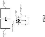
- Each of the antenna taps 104 is connected to two of the conductors 102, as shown in the diagram of FIG. 2 .
- a subset of two of the conductors 102a, 102b is depicted, along with an associated antenna tap 104, RF switch 106 and transmission lines 108.
- the antenna taps 104 may take various forms.
- the antenna taps 104 may be balanced transmission lines and/or unbalanced transmission lines.
- the antenna tap 104 comprises a coaxial dual conductor having two balanced transmission lines, wherein a first transmission line is electrically connected to the first conductor 102a, while a second transmission line is electrically connected to the second conductor 102b.
- the antenna tap 104 comprises a ribbon cable having two or more unbalanced transmission lines.
- ⁇ ' N is the minimum wavelength in the RF band ⁇ f N .
- the following functions are performed:
- the power received by the antenna taps 104 is recovered by the combiner 110 to decrease the impact of reduced efficiency in the antenna 100.
- the combiner 110 combines the power received by the antenna taps 104 at the output port 112. In this manner, power received by the antenna taps 104 is captured and used in a manner that provides improved gain for the antenna 100.
- Each port 112 of the combiners 110 may be connected to various elements, such that an electrical signal received by the antenna 100 may be processed by the elements, and an electrical signal generated by the elements may be transmitted by the antenna 100.
- Such elements may be any electrical or electronic device or system for processing RF signals.
- the devices or systems provide specific applications onboard an aircraft, such as radio communications systems, satellite communications (SATCOM) systems, global positioning satellite (GPS) navigation systems, transponder systems, radar systems, Traffic alert and Collision Avoidance System (TCAS) systems, electronic warfare systems, instrument landing systems, etc.
- SATCOM satellite communications
- GPS global positioning satellite
- TCAS Traffic alert and Collision Avoidance System
- the antenna 100 is shown as being mounted on a structure 114.
- a structure 114 may comprise, for example, an aircraft skin panel, although other structures 114 may be used.
- the antenna 100 may be conformal to a surface of the structure 114.
- Other components for the multi-tap antenna 100 may be located on the structure 114 or elsewhere.
- the illustration of the antenna 100 in FIG. 1 is not meant to imply physical or architectural limitations to the manner in which different embodiments may be implemented.
- the antenna 100 may be implemented using any number of different components and different dimensions.
Landscapes
- Variable-Direction Aerials And Aerial Arrays (AREA)
- Details Of Aerials (AREA)
Abstract
Description
- The invention is related generally to the field of antennas, and more particularly, to a dynamically allocated broadband multi-tap antenna.
- Antennas are used in many different systems and applications, such as communications, global positioning, radar, transponders, and other systems and applications. For example, antennas may be used on aircraft or other vehicles to provide for these and other functions. In many cases, physical space on vehicles is limited. Therefore, it is desirable to have an antenna that is as small as possible.
- Antenna size is defined here in terms of wavelengths. A small antenna is defined as one that is a fraction of a wavelength in size. One way to make an antenna small is to sacrifice bandwidth.
- Small antennas are typically either narrow band or inefficient. For example, small broadband antennas have significant dissipative loss, which reduces gain. This dissipative loss allows the small antenna to operate in a broadband manner, but reduces its efficiency. Nonetheless, with a broadband antenna, a single antenna may be used in place of multiple antennas that operate at different frequencies.
- Thus, there is a need for small antenna structures that operate in a broadband manner, but reduce loss, in order to maximize efficiency. The present invention satisfies this need.
- To overcome the limitations in the prior art described above, and to overcome other limitations that will become apparent upon reading and understanding the present specification, a dynamically allocated broadband multi-tap antenna is disclosed, as well as a method of using the antenna and a method of making the antenna.
- The dynamically allocated broadband multi-tap antenna comprises a plurality of conductors, wherein the conductors are sub-wavelength conductors used for transmitting and/or receiving radio frequency (RF) signals; a plurality of antenna taps, wherein each of the antenna taps is connected to one or more of the conductors; a plurality of RF switches, wherein each of the RF switches is connected to one of the antenna taps; and a plurality of combiners (which also act as splitters), wherein each of the combiners is connected to one or more of the RF switches.
- One or more of the RF switches are controlled to dynamically allocate one or more of the antenna taps to a selected one of the combiners, by interconnecting the one or more of the antenna taps with the selected one of the combiners via the RF switches, to communicate the RF signals between the conductors connected to the one or more of the antenna taps and the selected one of the combiners. Thus, the RF signals received by the conductors connected to the one or more of the antenna taps are combined into an output signal at a port of the selected one of the combiners, while an input signal from a port of the selected one of the combiners is split for transmission as the RF signals by the conductors connected to the one or more of the antenna taps.
- The features, functions, and advantages that have been discussed can be achieved independently in various embodiments or may be combined in yet other embodiments, further details of which can be seen with reference to the following description and drawings.
- Referring now to the drawings in which like reference numbers represent corresponding parts throughout:
-
FIG. 1 is a diagram of a dynamically allocated broadband multi-tap antenna according to one embodiment. -
FIG. 2 is a diagram showing an antenna tap connected to two conductors and a radio frequency (RF) switch according to one embodiment. - In the following description of the preferred embodiment, reference is made to the accompanying drawings which form a part hereof, and in which is shown by way of illustration specific embodiments in which the present invention may be practiced. It is to be understood that other embodiments may be utilized and structural changes may be made without departing from the scope of the present invention.
- A dynamically allocated broadband multi-tap antenna of relatively small size is comprised of a plurality of sub-wavelength conductors used for transmitting and/or receiving RF signals; a plurality of antenna taps, each of which is connected to one or more of the conductors; a plurality of RF switches, each of which is connected to one of the antenna taps; and a plurality of combiners (which are also splitters), each of which is connected to one or more of the RF switches. The RF switches are controlled to dynamically allocate the antenna taps to a selected combiner, by interconnecting the antenna taps with the selected combiner, to communicate the RF signals between the conductors connected to the antenna taps and the selected combiner. The RF signals received by the conductors connected to the antenna taps are combined into an output signal at a port of the selected combiner, or an input signal at a port of the selected combiner is split for transmission as the RF signals by the conductors connected to the antenna taps.
- Consequently, the dynamically allocated broadband multi-tap antenna maximizes both functionality and bandwidth. The sub-wavelength conductors and associated antenna taps enable broadband gain and pattern performance, which is especially useful at lower frequencies where antenna size limits overall bandwidth performance.
- Typically, lower frequency functions have their own antenna elements, which are physically separate from other functions and their associated antenna elements. The RF switches allow the dynamically allocated broadband multi-tap antenna to be used by more than one function, thereby reducing or eliminating the need for a separate antenna for each function, while allowing the antenna to be more easily integrated into environments with constraints on space.
-
FIG. 1 is a diagram of a dynamically allocated broadbandmulti-tap antenna 100 according to one embodiment. The dynamically allocated broadbandmulti-tap antenna 100 described herein is a compact or small antenna that meets limited physical space requirements, yet is both broadband and highly efficient. - In this embodiment, the
antenna 100 is comprised of a plurality ofconductors 102, a plurality ofantenna taps 104, a plurality ofRF switches 106, a plurality oftransmission lines 108, and a plurality of combiners 110 (which also perform as splitters). Theconductors 102 aresub-wavelength conductors 102 arranged in a linear array, and are used for transmitting and/or receiving RF signals. Each of theantenna taps 104 is connected to one or more of theconductors 102. Each of theRF switches 106 is connected to one of theantenna taps 104. Each of thecombiners 110 is connected to one or more of theRF switches 106 via thetransmission lines 108. One or more of theRF switches 106 are controlled, by thecombiners 110 or a separate controller (not shown), to dynamically allocate one or more of theantenna taps 104 to a selected one of thecombiners 110, by interconnecting the one or more of theantenna taps 104 with the selected one of thecombiners 110, to communicate the RF signals between theconductors 102 connected to the one or more of theantenna taps 104 and the selected one of thecombiners 110. Specifically, the RF signals received by theconductors 102 connected to the one or more of theantenna taps 104 are combined into an output signal at a port 112 of the selected one of thecombiners 110, or an input signal at a port 112 of the selected one of thecombiners 110 is split for transmission as the RF signals by theconductors 102 connected to the one or more of theantenna taps 104. These and other aspects are described in more detail below. - In one embodiment, the
conductors 102 comprise metal patches, although theconductors 102 may be any type of conductive material, which function as transducers to send and receive RF signals. There are 18conductors 102 shown in the example ofFIG. 1 , but any number ofconductors 102 may be used. - Typical dimensions the
conductors 102 are on the order of 1/10th the wavelength at the lowest frequency of the radio frequency band of operation (1 foot at 100 MHz) with loads (taps 104) spaced about 1/100th of a wavelength apart. In the example ofFIG. 1 , each of theconductors 102 is about one-half inch long by one inch wide, although any size ofconductors 102 may be used. - An
antenna tap 104 is a location on a structure of theantenna 100 from which power may be collected, dissipated, or distributed. Theconductors 102 are selected to maximize the power delivered at the desired frequency over the widest angles possible to theantenna taps 104. - The antenna taps 104 connect the
conductors 102 to each other in a serial arrangement. The antenna taps 104 comprise resistive materials that increase the bandwidth at which theantenna 100 can function. The antenna taps 104 function to provide loss to increase gain in theantenna 100 in these examples. - With
multiple taps 104, it is possible to collect or divert power from various locations on theantenna 100 structure into a single load or port. The use ofmultiple taps 104 has significant advantages for the reduction ofantenna 100 size and bandwidth without the constraints imposed by prior methods. - Each of the
antenna taps 104 is connected to two of theconductors 102, as shown in the diagram ofFIG. 2 . In this example, a subset of two of theconductors antenna tap 104,RF switch 106 andtransmission lines 108. - The antenna taps 104 may take various forms. For example, without limitation, the
antenna taps 104 may be balanced transmission lines and/or unbalanced transmission lines. In the embodiment ofFIG. 2 , theantenna tap 104 comprises a coaxial dual conductor having two balanced transmission lines, wherein a first transmission line is electrically connected to thefirst conductor 102a, while a second transmission line is electrically connected to thesecond conductor 102b. In other embodiments, theantenna tap 104 comprises a ribbon cable having two or more unbalanced transmission lines. - Referring again to
FIG. 1 , the use ofRF switches 106 with the antenna taps 104 andconductors 102 broadens the bandwidth of theantenna 100. Assume that λ'N is the minimum wavelength in the RF band Δf N. In the example ofFIG. 1 , as indicated by the annotations above theconductors 102, the following functions are performed: - the RF switches 106 are controlled to select the first 3 antenna taps 104 and the first 4
conductors 102, which forms an element at a half wavelength λ'1/2 or less for the frequency band Δf 1, in order to combine the signals into an output signal atElement 1 Tx/Rx port 112a of thecombiner 110a; - the RF switches 106 are controlled to select the first 6 antenna taps 104 and the first 7
conductors 102, which forms an element at a half wavelength λ'2/2 or less for the frequency band Δf 2, in order to combine the signals into an output signal atElement 2 Tx/Rx port 112b of thecombiner 110b; and - the RF switches 106 are controlled to select the first 10 antenna taps 104 and the first 11
conductors 102, which forms an element at a half wavelength λ'3/2 or less for the frequency band Δf 3, in order to combine the signals into an output signal atElement 3 Tx/Rx port 112c of thecombiner 110c. - Similar functions would be performed when splitting signals from the
combiners 110 to theconductors 102. - Moreover, the power received by the antenna taps 104 is recovered by the
combiner 110 to decrease the impact of reduced efficiency in theantenna 100. Thecombiner 110 combines the power received by the antenna taps 104 at the output port 112. In this manner, power received by the antenna taps 104 is captured and used in a manner that provides improved gain for theantenna 100. - Each port 112 of the
combiners 110 may be connected to various elements, such that an electrical signal received by theantenna 100 may be processed by the elements, and an electrical signal generated by the elements may be transmitted by theantenna 100. Such elements may be any electrical or electronic device or system for processing RF signals. In one embodiment, the devices or systems provide specific applications onboard an aircraft, such as radio communications systems, satellite communications (SATCOM) systems, global positioning satellite (GPS) navigation systems, transponder systems, radar systems, Traffic alert and Collision Avoidance System (TCAS) systems, electronic warfare systems, instrument landing systems, etc. - Also, in this example, the
antenna 100 is shown as being mounted on astructure 114. Such astructure 114 may comprise, for example, an aircraft skin panel, althoughother structures 114 may be used. With this type of implementation, theantenna 100 may be conformal to a surface of thestructure 114. Other components for themulti-tap antenna 100 may be located on thestructure 114 or elsewhere. - The description of the different embodiments set forth above has been presented for purposes of illustration and description, and is not intended to be exhaustive or limited to the embodiments in the form disclosed. Many modifications and variations will be apparent to those of ordinary skill in the art.
- For example, the illustration of the
antenna 100 inFIG. 1 is not meant to imply physical or architectural limitations to the manner in which different embodiments may be implemented. For example, theantenna 100 may be implemented using any number of different components and different dimensions. - Although the different embodiments have been described with respect to aircraft or other vehicles, other embodiments may be applied to other types of applications or structures. For example, the embodiments may be used on mobile platforms, stationary platforms, land, sea, air or space-based structures, and/or other suitable structures.
Further, the disclosure comprises embodiments according to the following clauses: -
Clause 1. An antenna, comprising:- a plurality of conductors, wherein the conductors are sub-wavelength conductors used for transmitting or receiving radio frequency (RF) signals;
- a plurality of antenna taps, wherein each of the antenna taps is connected to one or more of the conductors;
- a plurality of radio frequency (RF) switches, wherein each of the RF switches is connected to one of the antenna taps; and
- a plurality of combiners, wherein each of the combiners is connected to one or more of the RF switches;
- wherein one or more of the RF switches are controlled to dynamically allocate one or more of the antenna taps to a selected one of the combiners, by interconnecting the one or more of the antenna taps with the selected one of the combiners, to communicate the RF signals between the conductors connected to the one or more of the antenna taps and the selected one of the combiners.
-
Clause 2. The antenna ofClause 1, wherein the RF signals received by the conductors connected to the one or more of the antenna taps are combined into an output signal at a port of the selected one of the combiners. -
Clause 3. The antenna ofClause - Clause 4. The antenna of
Clause - Clause 5. The antenna of any of Clauses 1-4, wherein the conductors are arranged in a linear array.
- Clause 6. The antenna of any of Clauses 1-5, wherein the antenna taps comprise resistive materials that increase a bandwidth at which the antenna functions.
- Clause 7. The antenna of any of Clauses 1-6, wherein the antenna taps connect the conductors to each other in a serial arrangement.
- Clause 8. The antenna of any of Clauses 1-7, wherein every two adjacent conductors are connected to one of the antenna taps.
- Clause 9. The antenna of any of Clauses 1-8, wherein the antenna taps comprise balanced or unbalanced transmission lines.
- Clause 10. The antenna of any of Clauses 1-9, wherein the conductors form an element at a desired frequency to maximize power delivered to the antenna taps at the desired frequency.
- Clause 11. A method of transmitting or receiving radio frequency signals, comprising:
- transmitting or receiving one or more radio frequency (RF) signals at an antenna, wherein the antenna comprises:
- a plurality of conductors, wherein the conductors are sub-wavelength conductors used for transmitting or receiving the RF signals;
- a plurality of antenna taps, wherein each of the antenna taps is connected to one or more of the conductors;
- a plurality of radio frequency (RF) switches, wherein each of the RF switches is connected to one of the antenna taps; and
- a plurality of combiners, wherein each of the combiners is connected to one or more of the RF switches; and
- controlling one or more of the RF switches to dynamically allocate one or more of the antenna taps to a selected one of the combiners, by interconnecting the one or more of the antenna taps with the selected one of the combiners, to communicate the RF signals between the conductors connected to the one or more of the antenna taps and the selected one of the combiners.
- transmitting or receiving one or more radio frequency (RF) signals at an antenna, wherein the antenna comprises:
- Clause 12. The method of Clause 11, wherein the RF signals received by the conductors connected to the one or more of the antenna taps are combined into an output signal at a port of the selected one of the combiners.
- Clause 13. The method of Clause 11 or 12, wherein an input signal at a port of the selected one of the combiners is split for transmission as the RF signals by the conductors connected to the one or more of the antenna taps.
- Clause 14. The method of Clause 11, 12 or 13, wherein the antenna is a broadband antenna used by more than one function, thereby reducing or eliminating the need for a separate antenna for each function, while allowing the antenna to be integrated into environments with constraints on space.
- Clause 15. The method of any of Clauses 11-14, wherein the conductors are arranged in a linear array.
- Clause 16. The method of any of Clauses 11-15, wherein the antenna taps act as resistive materials.
- Clause 17. The method of any of Clauses 11-16, wherein the antenna taps connect the conductors to each other in a serial arrangement.
- Clause 18. The method of any of Clauses 11-17, wherein every two adjacent conductors are connected to one of the antenna taps.
- Clause 19. The method of any of Clauses 11-18, wherein the antenna taps comprise balanced or unbalanced transmission lines.
- Clause 20. The method of any of Clauses 11-19, wherein the conductors form an element at a desired frequency to maximize power delivered to the antenna taps at the desired frequency.
- Clause 21. A method of fabricating an antenna, comprising:
- providing a plurality of conductors, wherein the conductors are sub-wavelength conductors used for transmitting or receiving radio frequency (RF) signals;
- connecting a plurality of antenna taps to the conductors, wherein each of the antenna taps is connected to one or more of the conductors;
- connecting a plurality of radio frequency (RF) switches to the antenna taps, wherein each of the RF switches is connected to one of the antenna taps; and
- connecting a plurality of combiners to the RF switches, wherein each of the combiners is connected to one or more of the RF switches;
- such that, when one or more of the RF switches are controlled to dynamically allocate one or more of the antenna taps to a selected one of the combiners, by interconnecting the one or more of the antenna taps with the selected one of the combiners, the RF signals are communicated between the conductors connected to the one or more of the antenna taps and the selected one of the combiners.
- It is intended that the scope of the invention be limited not by this detailed description, but rather by the claims appended hereto.
Claims (15)
- An antenna 100, comprising:a plurality of conductors 102, wherein the conductors 102 are sub-wavelength conductors 102 used for transmitting or receiving radio frequency (RF) signals;a plurality of antenna taps 104, wherein each of the antenna taps 104 is connected to one or more of the conductors 102;a plurality of radio frequency (RF) switches 106, wherein each of the RF switches 106 is connected to one of the antenna taps 104; anda plurality of combiners 110, wherein each of the combiners 110 is connected to one or more of the RF switches 106;wherein one or more of the RF switches 106 are controlled to dynamically allocate one or more of the antenna taps 104 to a selected one of the combiners 110, by interconnecting the one or more of the antenna taps 104 with the selected one of the combiners 110, to communicate the RF signals between the conductors 102 connected to the one or more of the antenna taps 104 and the selected one of the combiners 110.
- The antenna 100 of claim 1, wherein the RF signals received by the conductors 102 connected to the one or more of the antenna taps 104 are combined into an output signal at a port 112 of the selected one of the combiners 110.
- The antenna 100 of any one of claims 1-2, wherein an input signal at a port 112 of the selected one of the combiners 110 is split for transmission as the RF signals by the conductors 102 connected to the one or more of the antenna taps 104.
- The antenna 100 of any one of claims 1-3, wherein the antenna 100 is a broadband antenna 100 used by more than one function, thereby reducing or eliminating the need for a separate antenna for each function, while allowing the antenna 100 to be integrated into environments with constraints on space.
- The antenna 100 of any one of claims 1-4, wherein the conductors 102 are arranged in a linear array.
- The antenna 100 of any one of claims 1-5, wherein the antenna taps 104 comprise resistive materials that increase a bandwidth at which the antenna functions.
- The antenna 100 of any one of claims 1-6, wherein the antenna taps 104 connect the conductors 102 to each other in a serial arrangement.
- The antenna 100 of any one of claims 1-7, wherein every two adjacent conductors 102 are connected to one of the antenna taps 104.
- The antenna 100 of any one of claims 1-8, wherein the antenna taps 104 comprise balanced or unbalanced transmission lines 108.
- The antenna 100 of any one of claims 1-9, wherein the conductors 102 form an element at a desired frequency to maximize power delivered to the antenna taps 104 at the desired frequency.
- A method of transmitting or receiving radio frequency signals, comprising:transmitting or receiving one or more radio frequency (RF) signals at an antenna 100, wherein the antenna 100 comprises:a plurality of conductors 102, wherein the conductors 102 are sub-wavelength conductors 102 used for transmitting or receiving the RF signals;a plurality of antenna taps 104, wherein each of the antenna taps 104 is connected to one or more of the conductors 102;a plurality of radio frequency (RF) switches 106, wherein each of the RF switches 106 is connected to one of the antenna taps 104; anda plurality of combiners 110, wherein each of the combiners 110 is connected to one or more of the RF switches 106; andcontrolling one or more of the RF switches 106 to dynamically allocate one or more of the antenna taps 104 to a selected one of the combiners 110, by interconnecting the one or more of the antenna taps 104 with the selected one of the combiners 110, to communicate the RF signals between the conductors 102 connected to the one or more of the antenna taps 104 and the selected one of the combiners 110.
- The method of claim 11, wherein the RF signals received by the conductors 102 connected to the one or more of the antenna taps 104 are combined into an output signal at a port 112 of the selected one of the combiners 110.
- The method of any one of claims 11-12, wherein an input signal at a port 112 of the selected one of the combiners 110 is split for transmission as the RF signals by the conductors 102 connected to the one or more of the antenna taps 104.
- The method of any one of claims 11-13, wherein the antenna 100 is a broadband antenna 100 used by more than one function, thereby reducing or eliminating the need for a separate antenna for each function, while allowing the antenna 100 to be integrated into environments with constraints on space.
- The method of any one of claims 11-14, wherein the conductors 102 are arranged in a linear array.
Applications Claiming Priority (1)
| Application Number | Priority Date | Filing Date | Title |
|---|---|---|---|
| US15/135,002 US9985352B2 (en) | 2016-04-21 | 2016-04-21 | Dynamically allocated broadband multi-tap antenna |
Publications (2)
| Publication Number | Publication Date |
|---|---|
| EP3236532A1 true EP3236532A1 (en) | 2017-10-25 |
| EP3236532B1 EP3236532B1 (en) | 2020-02-05 |
Family
ID=58016602
Family Applications (1)
| Application Number | Title | Priority Date | Filing Date |
|---|---|---|---|
| EP17155543.6A Active EP3236532B1 (en) | 2016-04-21 | 2017-02-10 | Dynamically allocated broad band multi-tap antenna |
Country Status (4)
| Country | Link |
|---|---|
| US (1) | US9985352B2 (en) |
| EP (1) | EP3236532B1 (en) |
| JP (1) | JP6839596B2 (en) |
| CN (1) | CN107305975B (en) |
Cited By (1)
| Publication number | Priority date | Publication date | Assignee | Title |
|---|---|---|---|---|
| RU2859842C1 (en) * | 2025-01-31 | 2026-04-08 | Федеральное государственное казенное военное образовательное учреждение высшего образования "Рязанское гвардейское высшее воздушно-десантное ордена Суворова дважды Краснознаменное командное училище имени генерала армии В.Ф. Маргелова" Министерства обороны Российской Федерации | Frequency-tunable antenna |
Citations (5)
| Publication number | Priority date | Publication date | Assignee | Title |
|---|---|---|---|---|
| US5861844A (en) * | 1994-11-29 | 1999-01-19 | Qualcomm Incorporated | Method and apparatus for providing redundant coverage within a cellular communication system |
| EP1046962A2 (en) * | 1999-04-19 | 2000-10-25 | Advantest Corporation | Radio hologram observation apparatus and method therefor |
| US8063832B1 (en) * | 2008-04-14 | 2011-11-22 | University Of South Florida | Dual-feed series microstrip patch array |
| US20120068882A1 (en) * | 2009-02-12 | 2012-03-22 | Trw Automotive Us Llc | Antennas |
| US20130120216A1 (en) * | 2008-08-28 | 2013-05-16 | The Boeing Company | Broadband Multi-Tap Antenna |
Family Cites Families (13)
| Publication number | Priority date | Publication date | Assignee | Title |
|---|---|---|---|---|
| EP1012994A1 (en) * | 1997-03-03 | 2000-06-28 | Celletra Ltd. | Cellular communications systems |
| JP3326416B2 (en) * | 1998-10-30 | 2002-09-24 | 三洋電機株式会社 | Adaptive array device |
| US8363744B2 (en) * | 2001-06-10 | 2013-01-29 | Aloft Media, Llc | Method and system for robust, secure, and high-efficiency voice and packet transmission over ad-hoc, mesh, and MIMO communication networks |
| EP1258948A3 (en) * | 2001-05-17 | 2004-04-07 | Hitachi Kokusai Electric Inc. | Semicircular radial antenna |
| US6963314B2 (en) * | 2002-09-26 | 2005-11-08 | Andrew Corporation | Dynamically variable beamwidth and variable azimuth scanning antenna |
| US6809694B2 (en) * | 2002-09-26 | 2004-10-26 | Andrew Corporation | Adjustable beamwidth and azimuth scanning antenna with dipole elements |
| JP2009524980A (en) * | 2006-01-25 | 2009-07-02 | テレフオンアクチーボラゲット エル エム エリクソン(パブル) | Method and apparatus for reducing combiner loss in a multi-sector omni base station |
| US7876263B2 (en) * | 2009-02-24 | 2011-01-25 | Raytheon Company | Asymmetrically thinned active array TR module and antenna architecture |
| US20110250926A1 (en) * | 2009-12-21 | 2011-10-13 | Qualcomm Incorporated | Dynamic antenna selection in a wireless device |
| US8521172B2 (en) * | 2011-01-11 | 2013-08-27 | Scott R. Rosenau | Method and system for switching cellular base station capacity |
| US9166301B2 (en) * | 2012-02-13 | 2015-10-20 | AMI Research & Development, LLC | Travelling wave antenna feed structures |
| EP2669999B1 (en) * | 2012-05-31 | 2018-11-14 | Nxp B.V. | Adjustable antenna |
| CN204130694U (en) * | 2014-09-30 | 2015-01-28 | 深圳市中兴移动通信有限公司 | A kind of reconfigurable antenna |
-
2016
- 2016-04-21 US US15/135,002 patent/US9985352B2/en active Active
-
2017
- 2017-02-10 EP EP17155543.6A patent/EP3236532B1/en active Active
- 2017-04-11 CN CN201710231756.0A patent/CN107305975B/en active Active
- 2017-04-13 JP JP2017079559A patent/JP6839596B2/en active Active
Patent Citations (5)
| Publication number | Priority date | Publication date | Assignee | Title |
|---|---|---|---|---|
| US5861844A (en) * | 1994-11-29 | 1999-01-19 | Qualcomm Incorporated | Method and apparatus for providing redundant coverage within a cellular communication system |
| EP1046962A2 (en) * | 1999-04-19 | 2000-10-25 | Advantest Corporation | Radio hologram observation apparatus and method therefor |
| US8063832B1 (en) * | 2008-04-14 | 2011-11-22 | University Of South Florida | Dual-feed series microstrip patch array |
| US20130120216A1 (en) * | 2008-08-28 | 2013-05-16 | The Boeing Company | Broadband Multi-Tap Antenna |
| US20120068882A1 (en) * | 2009-02-12 | 2012-03-22 | Trw Automotive Us Llc | Antennas |
Cited By (1)
| Publication number | Priority date | Publication date | Assignee | Title |
|---|---|---|---|---|
| RU2859842C1 (en) * | 2025-01-31 | 2026-04-08 | Федеральное государственное казенное военное образовательное учреждение высшего образования "Рязанское гвардейское высшее воздушно-десантное ордена Суворова дважды Краснознаменное командное училище имени генерала армии В.Ф. Маргелова" Министерства обороны Российской Федерации | Frequency-tunable antenna |
Also Published As
| Publication number | Publication date |
|---|---|
| CN107305975A (en) | 2017-10-31 |
| US20170310010A1 (en) | 2017-10-26 |
| CN107305975B (en) | 2020-10-30 |
| US9985352B2 (en) | 2018-05-29 |
| JP2017195594A (en) | 2017-10-26 |
| EP3236532B1 (en) | 2020-02-05 |
| JP6839596B2 (en) | 2021-03-10 |
Similar Documents
| Publication | Publication Date | Title |
|---|---|---|
| US10950939B2 (en) | Systems and methods for ultra-ultra-wide band AESA | |
| US11715880B2 (en) | Waveguide feed network architecture for wideband, low profile, dual polarized planar horn array antennas | |
| US10389041B2 (en) | Phased array antenna panel with enhanced isolation and reduced loss | |
| EP3358676A1 (en) | Module, wireless communication apparatus, and radar apparatus | |
| EP2425490B1 (en) | Broadband antenna system for satellite communication | |
| US20100117886A1 (en) | Distributed and cable reduced tcas | |
| EP2551959A1 (en) | Wide-band linked-ring antenna element for phased arrays | |
| US20120127034A1 (en) | Phased Array Antenna with Reduced Component Count | |
| US20180069604A1 (en) | Transceiver for Concurrently Transmitting and Receiving Wireless Signals | |
| US9960485B2 (en) | Antenna device using EBG structure, wireless communication device, and radar device | |
| US7385560B1 (en) | Aircraft directional/omnidirectional antenna arrangement | |
| US11075456B1 (en) | Printed board antenna system | |
| US8810470B2 (en) | Dual band antenna, in particular for satellite navigation applications | |
| EP3783810A1 (en) | Electronically scanned array leaky wave phase shift network | |
| EP1464094B1 (en) | Communications antenna system and mobile transmit and receive reflector antenna | |
| US9985352B2 (en) | Dynamically allocated broadband multi-tap antenna | |
| US11158951B2 (en) | Antipodal vivaldi antenna systems | |
| US20160329916A1 (en) | Multiband communications and repeater system | |
| Saputeraa et al. | Franklin Collinear Antenna 2 Levels Different Sides using Array Method 4 Stacking Units 360ᵒ with Integrated Reflector and Power Combiner for ADS-B S-Receiver Mode | |
| Jaworski et al. | Highly integrated ligthweight dual band antenna with dual or quadruple polarization agility | |
| PL205794B1 (en) | Method and system designed for generating additional reception beam in a multi-beam radar |
Legal Events
| Date | Code | Title | Description |
|---|---|---|---|
| PUAI | Public reference made under article 153(3) epc to a published international application that has entered the european phase |
Free format text: ORIGINAL CODE: 0009012 |
|
| STAA | Information on the status of an ep patent application or granted ep patent |
Free format text: STATUS: REQUEST FOR EXAMINATION WAS MADE |
|
| 17P | Request for examination filed |
Effective date: 20170210 |
|
| AK | Designated contracting states |
Kind code of ref document: A1 Designated state(s): AL AT BE BG CH CY CZ DE DK EE ES FI FR GB GR HR HU IE IS IT LI LT LU LV MC MK MT NL NO PL PT RO RS SE SI SK SM TR |
|
| AX | Request for extension of the european patent |
Extension state: BA ME |
|
| STAA | Information on the status of an ep patent application or granted ep patent |
Free format text: STATUS: EXAMINATION IS IN PROGRESS |
|
| 17Q | First examination report despatched |
Effective date: 20180726 |
|
| GRAP | Despatch of communication of intention to grant a patent |
Free format text: ORIGINAL CODE: EPIDOSNIGR1 |
|
| STAA | Information on the status of an ep patent application or granted ep patent |
Free format text: STATUS: GRANT OF PATENT IS INTENDED |
|
| RIC1 | Information provided on ipc code assigned before grant |
Ipc: H01Q 5/50 20150101ALI20190621BHEP Ipc: H01Q 21/00 20060101ALI20190621BHEP Ipc: H01Q 3/24 20060101ALI20190621BHEP Ipc: H01Q 21/08 20060101AFI20190621BHEP |
|
| INTG | Intention to grant announced |
Effective date: 20190708 |
|
| GRAS | Grant fee paid |
Free format text: ORIGINAL CODE: EPIDOSNIGR3 |
|
| GRAA | (expected) grant |
Free format text: ORIGINAL CODE: 0009210 |
|
| STAA | Information on the status of an ep patent application or granted ep patent |
Free format text: STATUS: THE PATENT HAS BEEN GRANTED |
|
| AK | Designated contracting states |
Kind code of ref document: B1 Designated state(s): AL AT BE BG CH CY CZ DE DK EE ES FI FR GB GR HR HU IE IS IT LI LT LU LV MC MK MT NL NO PL PT RO RS SE SI SK SM TR |
|
| REG | Reference to a national code |
Ref country code: GB Ref legal event code: FG4D |
|
| REG | Reference to a national code |
Ref country code: AT Ref legal event code: REF Ref document number: 1230516 Country of ref document: AT Kind code of ref document: T Effective date: 20200215 |
|
| REG | Reference to a national code |
Ref country code: DE Ref legal event code: R096 Ref document number: 602017011319 Country of ref document: DE |
|
| REG | Reference to a national code |
Ref country code: IE Ref legal event code: FG4D |
|
| REG | Reference to a national code |
Ref country code: CH Ref legal event code: EP |
|
| REG | Reference to a national code |
Ref country code: NL Ref legal event code: MP Effective date: 20200205 |
|
| PG25 | Lapsed in a contracting state [announced via postgrant information from national office to epo] |
Ref country code: RS Free format text: LAPSE BECAUSE OF FAILURE TO SUBMIT A TRANSLATION OF THE DESCRIPTION OR TO PAY THE FEE WITHIN THE PRESCRIBED TIME-LIMIT Effective date: 20200205 Ref country code: PT Free format text: LAPSE BECAUSE OF FAILURE TO SUBMIT A TRANSLATION OF THE DESCRIPTION OR TO PAY THE FEE WITHIN THE PRESCRIBED TIME-LIMIT Effective date: 20200628 Ref country code: FI Free format text: LAPSE BECAUSE OF FAILURE TO SUBMIT A TRANSLATION OF THE DESCRIPTION OR TO PAY THE FEE WITHIN THE PRESCRIBED TIME-LIMIT Effective date: 20200205 Ref country code: NO Free format text: LAPSE BECAUSE OF FAILURE TO SUBMIT A TRANSLATION OF THE DESCRIPTION OR TO PAY THE FEE WITHIN THE PRESCRIBED TIME-LIMIT Effective date: 20200505 |
|
| REG | Reference to a national code |
Ref country code: LT Ref legal event code: MG4D |
|
| PG25 | Lapsed in a contracting state [announced via postgrant information from national office to epo] |
Ref country code: SE Free format text: LAPSE BECAUSE OF FAILURE TO SUBMIT A TRANSLATION OF THE DESCRIPTION OR TO PAY THE FEE WITHIN THE PRESCRIBED TIME-LIMIT Effective date: 20200205 Ref country code: LV Free format text: LAPSE BECAUSE OF FAILURE TO SUBMIT A TRANSLATION OF THE DESCRIPTION OR TO PAY THE FEE WITHIN THE PRESCRIBED TIME-LIMIT Effective date: 20200205 Ref country code: HR Free format text: LAPSE BECAUSE OF FAILURE TO SUBMIT A TRANSLATION OF THE DESCRIPTION OR TO PAY THE FEE WITHIN THE PRESCRIBED TIME-LIMIT Effective date: 20200205 Ref country code: IS Free format text: LAPSE BECAUSE OF FAILURE TO SUBMIT A TRANSLATION OF THE DESCRIPTION OR TO PAY THE FEE WITHIN THE PRESCRIBED TIME-LIMIT Effective date: 20200605 Ref country code: GR Free format text: LAPSE BECAUSE OF FAILURE TO SUBMIT A TRANSLATION OF THE DESCRIPTION OR TO PAY THE FEE WITHIN THE PRESCRIBED TIME-LIMIT Effective date: 20200506 Ref country code: BG Free format text: LAPSE BECAUSE OF FAILURE TO SUBMIT A TRANSLATION OF THE DESCRIPTION OR TO PAY THE FEE WITHIN THE PRESCRIBED TIME-LIMIT Effective date: 20200505 |
|
| PG25 | Lapsed in a contracting state [announced via postgrant information from national office to epo] |
Ref country code: NL Free format text: LAPSE BECAUSE OF FAILURE TO SUBMIT A TRANSLATION OF THE DESCRIPTION OR TO PAY THE FEE WITHIN THE PRESCRIBED TIME-LIMIT Effective date: 20200205 |
|
| REG | Reference to a national code |
Ref country code: CH Ref legal event code: PL |
|
| REG | Reference to a national code |
Ref country code: BE Ref legal event code: MM Effective date: 20200229 |
|
| PG25 | Lapsed in a contracting state [announced via postgrant information from national office to epo] |
Ref country code: SK Free format text: LAPSE BECAUSE OF FAILURE TO SUBMIT A TRANSLATION OF THE DESCRIPTION OR TO PAY THE FEE WITHIN THE PRESCRIBED TIME-LIMIT Effective date: 20200205 Ref country code: RO Free format text: LAPSE BECAUSE OF FAILURE TO SUBMIT A TRANSLATION OF THE DESCRIPTION OR TO PAY THE FEE WITHIN THE PRESCRIBED TIME-LIMIT Effective date: 20200205 Ref country code: CZ Free format text: LAPSE BECAUSE OF FAILURE TO SUBMIT A TRANSLATION OF THE DESCRIPTION OR TO PAY THE FEE WITHIN THE PRESCRIBED TIME-LIMIT Effective date: 20200205 Ref country code: EE Free format text: LAPSE BECAUSE OF FAILURE TO SUBMIT A TRANSLATION OF THE DESCRIPTION OR TO PAY THE FEE WITHIN THE PRESCRIBED TIME-LIMIT Effective date: 20200205 Ref country code: LT Free format text: LAPSE BECAUSE OF FAILURE TO SUBMIT A TRANSLATION OF THE DESCRIPTION OR TO PAY THE FEE WITHIN THE PRESCRIBED TIME-LIMIT Effective date: 20200205 Ref country code: SM Free format text: LAPSE BECAUSE OF FAILURE TO SUBMIT A TRANSLATION OF THE DESCRIPTION OR TO PAY THE FEE WITHIN THE PRESCRIBED TIME-LIMIT Effective date: 20200205 Ref country code: LU Free format text: LAPSE BECAUSE OF NON-PAYMENT OF DUE FEES Effective date: 20200210 Ref country code: DK Free format text: LAPSE BECAUSE OF FAILURE TO SUBMIT A TRANSLATION OF THE DESCRIPTION OR TO PAY THE FEE WITHIN THE PRESCRIBED TIME-LIMIT Effective date: 20200205 Ref country code: ES Free format text: LAPSE BECAUSE OF FAILURE TO SUBMIT A TRANSLATION OF THE DESCRIPTION OR TO PAY THE FEE WITHIN THE PRESCRIBED TIME-LIMIT Effective date: 20200205 |
|
| REG | Reference to a national code |
Ref country code: DE Ref legal event code: R097 Ref document number: 602017011319 Country of ref document: DE |
|
| REG | Reference to a national code |
Ref country code: AT Ref legal event code: MK05 Ref document number: 1230516 Country of ref document: AT Kind code of ref document: T Effective date: 20200205 |
|
| PG25 | Lapsed in a contracting state [announced via postgrant information from national office to epo] |
Ref country code: LI Free format text: LAPSE BECAUSE OF NON-PAYMENT OF DUE FEES Effective date: 20200229 Ref country code: CH Free format text: LAPSE BECAUSE OF NON-PAYMENT OF DUE FEES Effective date: 20200229 Ref country code: MC Free format text: LAPSE BECAUSE OF FAILURE TO SUBMIT A TRANSLATION OF THE DESCRIPTION OR TO PAY THE FEE WITHIN THE PRESCRIBED TIME-LIMIT Effective date: 20200205 |
|
| PLBE | No opposition filed within time limit |
Free format text: ORIGINAL CODE: 0009261 |
|
| STAA | Information on the status of an ep patent application or granted ep patent |
Free format text: STATUS: NO OPPOSITION FILED WITHIN TIME LIMIT |
|
| 26N | No opposition filed |
Effective date: 20201106 |
|
| PG25 | Lapsed in a contracting state [announced via postgrant information from national office to epo] |
Ref country code: AT Free format text: LAPSE BECAUSE OF FAILURE TO SUBMIT A TRANSLATION OF THE DESCRIPTION OR TO PAY THE FEE WITHIN THE PRESCRIBED TIME-LIMIT Effective date: 20200205 Ref country code: IE Free format text: LAPSE BECAUSE OF NON-PAYMENT OF DUE FEES Effective date: 20200210 Ref country code: IT Free format text: LAPSE BECAUSE OF FAILURE TO SUBMIT A TRANSLATION OF THE DESCRIPTION OR TO PAY THE FEE WITHIN THE PRESCRIBED TIME-LIMIT Effective date: 20200205 |
|
| PG25 | Lapsed in a contracting state [announced via postgrant information from national office to epo] |
Ref country code: BE Free format text: LAPSE BECAUSE OF NON-PAYMENT OF DUE FEES Effective date: 20200229 Ref country code: SI Free format text: LAPSE BECAUSE OF FAILURE TO SUBMIT A TRANSLATION OF THE DESCRIPTION OR TO PAY THE FEE WITHIN THE PRESCRIBED TIME-LIMIT Effective date: 20200205 Ref country code: PL Free format text: LAPSE BECAUSE OF FAILURE TO SUBMIT A TRANSLATION OF THE DESCRIPTION OR TO PAY THE FEE WITHIN THE PRESCRIBED TIME-LIMIT Effective date: 20200205 |
|
| PG25 | Lapsed in a contracting state [announced via postgrant information from national office to epo] |
Ref country code: TR Free format text: LAPSE BECAUSE OF FAILURE TO SUBMIT A TRANSLATION OF THE DESCRIPTION OR TO PAY THE FEE WITHIN THE PRESCRIBED TIME-LIMIT Effective date: 20200205 Ref country code: MT Free format text: LAPSE BECAUSE OF FAILURE TO SUBMIT A TRANSLATION OF THE DESCRIPTION OR TO PAY THE FEE WITHIN THE PRESCRIBED TIME-LIMIT Effective date: 20200205 Ref country code: CY Free format text: LAPSE BECAUSE OF FAILURE TO SUBMIT A TRANSLATION OF THE DESCRIPTION OR TO PAY THE FEE WITHIN THE PRESCRIBED TIME-LIMIT Effective date: 20200205 |
|
| PG25 | Lapsed in a contracting state [announced via postgrant information from national office to epo] |
Ref country code: MK Free format text: LAPSE BECAUSE OF FAILURE TO SUBMIT A TRANSLATION OF THE DESCRIPTION OR TO PAY THE FEE WITHIN THE PRESCRIBED TIME-LIMIT Effective date: 20200205 Ref country code: AL Free format text: LAPSE BECAUSE OF FAILURE TO SUBMIT A TRANSLATION OF THE DESCRIPTION OR TO PAY THE FEE WITHIN THE PRESCRIBED TIME-LIMIT Effective date: 20200205 |
|
| P01 | Opt-out of the competence of the unified patent court (upc) registered |
Effective date: 20230516 |
|
| PGFP | Annual fee paid to national office [announced via postgrant information from national office to epo] |
Ref country code: GB Payment date: 20260227 Year of fee payment: 10 |
|
| PGFP | Annual fee paid to national office [announced via postgrant information from national office to epo] |
Ref country code: DE Payment date: 20260227 Year of fee payment: 10 |
|
| PGFP | Annual fee paid to national office [announced via postgrant information from national office to epo] |
Ref country code: FR Payment date: 20260225 Year of fee payment: 10 |