EP3236409A1 - System for predicting residual lifespan of fire-damaged concrete structure and method therefor - Google Patents
System for predicting residual lifespan of fire-damaged concrete structure and method therefor Download PDFInfo
- Publication number
- EP3236409A1 EP3236409A1 EP15870195.3A EP15870195A EP3236409A1 EP 3236409 A1 EP3236409 A1 EP 3236409A1 EP 15870195 A EP15870195 A EP 15870195A EP 3236409 A1 EP3236409 A1 EP 3236409A1
- Authority
- EP
- European Patent Office
- Prior art keywords
- fire
- concrete structure
- data
- analysis
- damaged concrete
- Prior art date
- Legal status (The legal status is an assumption and is not a legal conclusion. Google has not performed a legal analysis and makes no representation as to the accuracy of the status listed.)
- Granted
Links
- 239000004567 concrete Substances 0.000 title claims abstract description 231
- 238000000034 method Methods 0.000 title claims abstract description 28
- 238000004458 analytical method Methods 0.000 claims abstract description 99
- 239000000126 substance Substances 0.000 claims abstract description 67
- 230000006378 damage Effects 0.000 claims abstract description 62
- 239000011148 porous material Substances 0.000 claims description 118
- 230000008859 change Effects 0.000 claims description 34
- 238000002441 X-ray diffraction Methods 0.000 claims description 26
- 238000003745 diagnosis Methods 0.000 claims description 23
- 238000010438 heat treatment Methods 0.000 claims description 22
- 238000005259 measurement Methods 0.000 claims description 17
- 238000007405 data analysis Methods 0.000 claims description 14
- VYPSYNLAJGMNEJ-UHFFFAOYSA-N Silicium dioxide Chemical compound O=[Si]=O VYPSYNLAJGMNEJ-UHFFFAOYSA-N 0.000 claims description 10
- 239000004570 mortar (masonry) Substances 0.000 claims description 8
- 238000012360 testing method Methods 0.000 claims description 8
- 238000005553 drilling Methods 0.000 claims description 5
- 238000000547 structure data Methods 0.000 claims description 2
- 230000002787 reinforcement Effects 0.000 abstract description 19
- 230000008439 repair process Effects 0.000 abstract description 4
- 238000010586 diagram Methods 0.000 description 23
- 238000001179 sorption measurement Methods 0.000 description 20
- IJGRMHOSHXDMSA-UHFFFAOYSA-N Atomic nitrogen Chemical compound N#N IJGRMHOSHXDMSA-UHFFFAOYSA-N 0.000 description 19
- CURLTUGMZLYLDI-UHFFFAOYSA-N Carbon dioxide Chemical compound O=C=O CURLTUGMZLYLDI-UHFFFAOYSA-N 0.000 description 17
- 239000004568 cement Substances 0.000 description 17
- 238000009826 distribution Methods 0.000 description 17
- XLYOFNOQVPJJNP-UHFFFAOYSA-N water Substances O XLYOFNOQVPJJNP-UHFFFAOYSA-N 0.000 description 16
- AXCZMVOFGPJBDE-UHFFFAOYSA-L calcium dihydroxide Chemical compound [OH-].[OH-].[Ca+2] AXCZMVOFGPJBDE-UHFFFAOYSA-L 0.000 description 10
- 229910002092 carbon dioxide Inorganic materials 0.000 description 9
- 239000000920 calcium hydroxide Substances 0.000 description 8
- 229910001861 calcium hydroxide Inorganic materials 0.000 description 8
- 239000001569 carbon dioxide Substances 0.000 description 8
- 229910001873 dinitrogen Inorganic materials 0.000 description 7
- 239000000203 mixture Substances 0.000 description 7
- 239000000463 material Substances 0.000 description 6
- 229910052757 nitrogen Inorganic materials 0.000 description 6
- 239000002356 single layer Substances 0.000 description 6
- 230000036571 hydration Effects 0.000 description 5
- 238000006703 hydration reaction Methods 0.000 description 5
- 239000000292 calcium oxide Substances 0.000 description 4
- ODINCKMPIJJUCX-UHFFFAOYSA-N calcium oxide Inorganic materials [Ca]=O ODINCKMPIJJUCX-UHFFFAOYSA-N 0.000 description 4
- 230000015556 catabolic process Effects 0.000 description 4
- 239000007795 chemical reaction product Substances 0.000 description 4
- 238000006731 degradation reaction Methods 0.000 description 4
- 239000007789 gas Substances 0.000 description 4
- 150000004677 hydrates Chemical class 0.000 description 4
- 239000000047 product Substances 0.000 description 4
- 239000007787 solid Substances 0.000 description 4
- 229910021532 Calcite Inorganic materials 0.000 description 3
- 239000000499 gel Substances 0.000 description 3
- 229910052500 inorganic mineral Inorganic materials 0.000 description 3
- 239000011707 mineral Substances 0.000 description 3
- 230000035515 penetration Effects 0.000 description 3
- 230000000704 physical effect Effects 0.000 description 3
- 230000006399 behavior Effects 0.000 description 2
- BRPQOXSCLDDYGP-UHFFFAOYSA-N calcium oxide Chemical compound [O-2].[Ca+2] BRPQOXSCLDDYGP-UHFFFAOYSA-N 0.000 description 2
- 238000006243 chemical reaction Methods 0.000 description 2
- 239000000470 constituent Substances 0.000 description 2
- 238000010276 construction Methods 0.000 description 2
- 230000018044 dehydration Effects 0.000 description 2
- 238000006297 dehydration reaction Methods 0.000 description 2
- 230000006866 deterioration Effects 0.000 description 2
- 238000005516 engineering process Methods 0.000 description 2
- 238000002474 experimental method Methods 0.000 description 2
- 230000003993 interaction Effects 0.000 description 2
- 239000010410 layer Substances 0.000 description 2
- 239000007788 liquid Substances 0.000 description 2
- 238000002156 mixing Methods 0.000 description 2
- 239000000843 powder Substances 0.000 description 2
- 229920006395 saturated elastomer Polymers 0.000 description 2
- UGFAIRIUMAVXCW-UHFFFAOYSA-N Carbon monoxide Chemical compound [O+]#[C-] UGFAIRIUMAVXCW-UHFFFAOYSA-N 0.000 description 1
- 229910000831 Steel Inorganic materials 0.000 description 1
- 230000005856 abnormality Effects 0.000 description 1
- 239000002156 adsorbate Substances 0.000 description 1
- 230000032683 aging Effects 0.000 description 1
- 239000003513 alkali Substances 0.000 description 1
- QVGXLLKOCUKJST-UHFFFAOYSA-N atomic oxygen Chemical group [O] QVGXLLKOCUKJST-UHFFFAOYSA-N 0.000 description 1
- 230000015572 biosynthetic process Effects 0.000 description 1
- 238000009835 boiling Methods 0.000 description 1
- 239000000378 calcium silicate Substances 0.000 description 1
- 229960003340 calcium silicate Drugs 0.000 description 1
- 229910052918 calcium silicate Inorganic materials 0.000 description 1
- 235000012241 calcium silicate Nutrition 0.000 description 1
- OYACROKNLOSFPA-UHFFFAOYSA-N calcium;dioxido(oxo)silane Chemical compound [Ca+2].[O-][Si]([O-])=O OYACROKNLOSFPA-UHFFFAOYSA-N 0.000 description 1
- 229910052799 carbon Inorganic materials 0.000 description 1
- 229910002091 carbon monoxide Inorganic materials 0.000 description 1
- 229910052729 chemical element Inorganic materials 0.000 description 1
- 239000011248 coating agent Substances 0.000 description 1
- 239000011247 coating layer Substances 0.000 description 1
- 238000000576 coating method Methods 0.000 description 1
- 238000010835 comparative analysis Methods 0.000 description 1
- 230000000052 comparative effect Effects 0.000 description 1
- 238000009833 condensation Methods 0.000 description 1
- 230000005494 condensation Effects 0.000 description 1
- 230000001186 cumulative effect Effects 0.000 description 1
- 238000000354 decomposition reaction Methods 0.000 description 1
- 238000013461 design Methods 0.000 description 1
- 238000011161 development Methods 0.000 description 1
- 230000018109 developmental process Effects 0.000 description 1
- 238000005315 distribution function Methods 0.000 description 1
- 238000001035 drying Methods 0.000 description 1
- 230000000694 effects Effects 0.000 description 1
- 238000007710 freezing Methods 0.000 description 1
- 230000008014 freezing Effects 0.000 description 1
- 238000003384 imaging method Methods 0.000 description 1
- 238000009616 inductively coupled plasma Methods 0.000 description 1
- 239000011229 interlayer Substances 0.000 description 1
- JEIPFZHSYJVQDO-UHFFFAOYSA-N iron(III) oxide Inorganic materials O=[Fe]O[Fe]=O JEIPFZHSYJVQDO-UHFFFAOYSA-N 0.000 description 1
- 238000000691 measurement method Methods 0.000 description 1
- 230000007246 mechanism Effects 0.000 description 1
- 239000000155 melt Substances 0.000 description 1
- 230000004048 modification Effects 0.000 description 1
- 238000012986 modification Methods 0.000 description 1
- 238000006386 neutralization reaction Methods 0.000 description 1
- 229910052760 oxygen Inorganic materials 0.000 description 1
- 239000001301 oxygen Substances 0.000 description 1
- 238000002161 passivation Methods 0.000 description 1
- 238000002459 porosimetry Methods 0.000 description 1
- 238000007781 pre-processing Methods 0.000 description 1
- 238000012545 processing Methods 0.000 description 1
- 150000003839 salts Chemical class 0.000 description 1
- 239000011378 shotcrete Substances 0.000 description 1
- 238000004901 spalling Methods 0.000 description 1
- 239000010959 steel Substances 0.000 description 1
- 230000035882 stress Effects 0.000 description 1
- 230000008646 thermal stress Effects 0.000 description 1
Images


Classifications
-
- G—PHYSICS
- G06—COMPUTING; CALCULATING OR COUNTING
- G06Q—INFORMATION AND COMMUNICATION TECHNOLOGY [ICT] SPECIALLY ADAPTED FOR ADMINISTRATIVE, COMMERCIAL, FINANCIAL, MANAGERIAL OR SUPERVISORY PURPOSES; SYSTEMS OR METHODS SPECIALLY ADAPTED FOR ADMINISTRATIVE, COMMERCIAL, FINANCIAL, MANAGERIAL OR SUPERVISORY PURPOSES, NOT OTHERWISE PROVIDED FOR
- G06Q10/00—Administration; Management
- G06Q10/04—Forecasting or optimisation specially adapted for administrative or management purposes, e.g. linear programming or "cutting stock problem"
-
- G—PHYSICS
- G01—MEASURING; TESTING
- G01N—INVESTIGATING OR ANALYSING MATERIALS BY DETERMINING THEIR CHEMICAL OR PHYSICAL PROPERTIES
- G01N33/00—Investigating or analysing materials by specific methods not covered by groups G01N1/00 - G01N31/00
- G01N33/38—Concrete; ceramics; glass; bricks
- G01N33/383—Concrete, cement
-
- G—PHYSICS
- G06—COMPUTING; CALCULATING OR COUNTING
- G06F—ELECTRIC DIGITAL DATA PROCESSING
- G06F16/00—Information retrieval; Database structures therefor; File system structures therefor
- G06F16/20—Information retrieval; Database structures therefor; File system structures therefor of structured data, e.g. relational data
- G06F16/24—Querying
- G06F16/245—Query processing
- G06F16/2452—Query translation
- G06F16/24528—Standardisation; Simplification
-
- G—PHYSICS
- G06—COMPUTING; CALCULATING OR COUNTING
- G06F—ELECTRIC DIGITAL DATA PROCESSING
- G06F16/00—Information retrieval; Database structures therefor; File system structures therefor
- G06F16/20—Information retrieval; Database structures therefor; File system structures therefor of structured data, e.g. relational data
- G06F16/24—Querying
- G06F16/245—Query processing
- G06F16/2455—Query execution
- G06F16/24553—Query execution of query operations
-
- G—PHYSICS
- G06—COMPUTING; CALCULATING OR COUNTING
- G06Q—INFORMATION AND COMMUNICATION TECHNOLOGY [ICT] SPECIALLY ADAPTED FOR ADMINISTRATIVE, COMMERCIAL, FINANCIAL, MANAGERIAL OR SUPERVISORY PURPOSES; SYSTEMS OR METHODS SPECIALLY ADAPTED FOR ADMINISTRATIVE, COMMERCIAL, FINANCIAL, MANAGERIAL OR SUPERVISORY PURPOSES, NOT OTHERWISE PROVIDED FOR
- G06Q50/00—Systems or methods specially adapted for specific business sectors, e.g. utilities or tourism
- G06Q50/08—Construction
-
- G—PHYSICS
- G06—COMPUTING; CALCULATING OR COUNTING
- G06Q—INFORMATION AND COMMUNICATION TECHNOLOGY [ICT] SPECIALLY ADAPTED FOR ADMINISTRATIVE, COMMERCIAL, FINANCIAL, MANAGERIAL OR SUPERVISORY PURPOSES; SYSTEMS OR METHODS SPECIALLY ADAPTED FOR ADMINISTRATIVE, COMMERCIAL, FINANCIAL, MANAGERIAL OR SUPERVISORY PURPOSES, NOT OTHERWISE PROVIDED FOR
- G06Q50/00—Systems or methods specially adapted for specific business sectors, e.g. utilities or tourism
- G06Q50/10—Services
- G06Q50/26—Government or public services
-
- B—PERFORMING OPERATIONS; TRANSPORTING
- B28—WORKING CEMENT, CLAY, OR STONE
- B28B—SHAPING CLAY OR OTHER CERAMIC COMPOSITIONS; SHAPING SLAG; SHAPING MIXTURES CONTAINING CEMENTITIOUS MATERIAL, e.g. PLASTER
- B28B11/00—Apparatus or processes for treating or working the shaped or preshaped articles
- B28B11/24—Apparatus or processes for treating or working the shaped or preshaped articles for curing, setting or hardening
- B28B11/245—Curing concrete articles
Abstract
Description
- The present invention relates to predicting a residual lifespan of a fire-damaged concrete structure, and more particularly, to a system and a method for collecting a very small amount of a sample from a fire-damaged concrete structure and performing a chemical analysis thereon to predict a residual lifespan of the fire-damaged concrete structure, and predicting the residual lifespan of the fire-damaged concrete structure by performing a comparative analysis of sample data with data pre-stored in a standardized database (DB) constructed through experiments.
- Generally, when a concrete structure is exposed to high temperature, such as in a fire or the like, for a long time, since hardened cement bodies and aggregates show different expansion and shrinkage behaviors, cracks appear or the structure is weakened, and physical properties and fire resistance are noticeably degraded. At this time, a change in pore structure and a chemical change are made, and thermal stress generated by confinement of an end part or the like may cause cracks which causes concrete deterioration and spalling.
- Specifically, a hardened cement body has a large amount of chemically-bonded water in addition to free water, and when the hardened body is exposed to 100 °C or higher, free water existing in capillary pores thereof evaporates, and a volume expansion of 1,300 times or more occurs. Also, an internal structure of a paste is loosened, which leads to an increase in pore volume and the development of cracks.
- Also, when a heating temperature further rises to about 180 °C, a part of the chemically-bonded water begins to evaporate from the hardened cement body. About 20 % of the water content of a calcium-silicate hydration product, which is a core hydrate for solidity of the hardened cement body, is lost at a range of about 250 °C to about 350 °C, and most of the water content is lost at a range of about 400 °C to 700 °C. Within a similar temperature range, calcium hydroxide (Ca(OH)2), which is a free alkali component in concrete, is also pyrolyzed into calcium oxide and water and chemically damaged. Also, since the number of slightly large pores increase and hardness is lost, the hardened cement body becomes structurally very dangerous. Subsequently, when the concrete is heated at about 1200 °C or higher for a long time, the concrete melts from a surface of the structure.
-
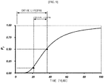
FIG. 1 is a diagram exemplifying compressive strength of a concrete structure being lowered with an increase in temperature during a fire. - As shown in
FIG. 1 , cement hydrates in concrete of the concrete structure undergo a chemical change in accordance to an increase in heating temperature, and a cement paste and an aggregate show contrary behaviors, that is, shrinkage and expansion, respectively, at temperatures up to about 600 °C. Further, as a result of the expansion of free water or the like existing in concrete capillary pores, internal stress gradually increases, and an internal structure is destroyed. Therefore, mechanical properties, such as solidity, elasticity, etc., are degraded. This is mainly because internal destruction resulting from a difference in a thermal expansion coefficient between the cement paste and the aggregate according to quality characteristics has influence on the mechanical properties of the concrete. - Here, the degree of degradation varies according to types, proportions, material ages, etc. of used materials and exhibits a tendency shown in
FIG. 1 . In other words, solidity is barely degraded up to 300 °C, but becomes 50 % or less above 500 °C. Also, at about 700 °C, solidity may be degraded to be in a range of about 60 % to 80 % of room-temperature compressive strength. Accordingly, it can be seen that compressive strength of concrete is noticeably degraded when the concrete is heated to a high temperature by a fire. Also, it can be seen that an elastic modulus is lowered by heat and is almost halved at 500 °C. This is because concrete lose elasticity and gradually becomes plastic when the concrete is heated to a high temperature. - Meanwhile, when a fire occurs, such a concrete structure is degraded in performance due to a change in a microstructure thereof. Such a change in microstructure can be identified from a pore distribution or pore structure characteristics using a gas adsorption method of adsorbing nitrogen onto a concrete structure at nitrogen's boiling point (-195.8 °C) to measure a pore structure thereof.
- To determine whether to reuse a fire-damaged concrete structure and a damage level thereof on the basis of a fire mechanism in such a concrete structure, it is necessary to accurately diagnose performance degradation of the concrete structure.
- However, up to now, there has been neither an expert nor technology for logically describing the degree of fire damage to a concrete structure in which a fire has occurred. In other words, since there has thus far been no technology for diagnosing a fire-damaged concrete structure, an appropriate assessment is not being made. Accordingly, it is necessary to develop an assessment tool for predicting a residual lifespan of a fire-damaged concrete structure.
-
- (Patent Literature 1) Korean Patent No.
10-631485 (date of filing: Mar 27, 2006 - (Patent Literature 2) Korean Patent No.
10-835848 (date of filing: Apr 19, 2006 - (Patent Literature 3) Korean Patent No.
10-894084 (date of filing: Oct 12, 2007 - (Patent Literature 4) Korean Patent No.
10-1128455 (date of filing: Aug 13, 2010 - To solve the above-described problem, the present invention is directed to providing a system and method for predicting a residual lifespan of a fire-damaged concrete structure which are capable of acquiring sample data by performing a chemical analysis on a sample of a fire-damaged concrete structure, and rapidly predicting a residual lifespan of the fire-damaged concrete structure by comparing the acquired sample data with data pre-stored in a standardized database (DB).
- The present invention is directed to providing a system and method for predicting a residual lifespan of a fire-damaged concrete structure which are capable of accurately and scientifically assessing a level of fire damage to a fire-damaged concrete structure so that the fire-damaged concrete structure can be appropriately repaired and reinforced.
- One aspect of the present invention provides a system for predicting a residual lifespan of a fire-damaged concrete structure, the system including: a fire-damaged concrete structure sample collected from a fire-damaged concrete structure and processed into a specimen for chemical analysis; a concrete structure residual lifespan prediction unit configured to diagnose fire damage to the fire-damaged concrete structure by comparing sample data with data pre-stored in a standardized database (DB), and assess a residual lifespan of the fire-damaged concrete structure; and the standardized DB constructed by storing data pre-acquired through an experiment, wherein the standardized DB standardizes and stores experimental data acquired through precise experimentation employing a fire-damaged concrete structure diagnosis device.
- Here, for an x-ray diffraction (XRD) analysis, a Brunauer-Emmett-Teller (BET) analysis, and an accelerated carbonation analysis test, the fire-damaged concrete structure diagnosis device may make a total of 20 measurements by making one measurement every time a heating temperature of a concrete structure specimen increases by 50 °C, and then store each piece of data to construct the standardized DB.
- Here, the fire-damaged concrete structure sample may be collected by drilling into the concrete structure to a target point using a mobile core drill, precisely processed, and then finely ground using an agate mortar set to be processed into the specimen for chemical analysis.
- Here, the concrete structure residual lifespan prediction unit may include: a chemical analysis unit configured to acquire the sample data by performing a chemical analysis on the fire-damaged concrete structure sample processed into the specimen for chemical analysis; a data analysis unit configured to separately predict a fire damage temperature, a pore structure, and a carbonation depth by comparing the sample data acquired by the chemical analysis unit with the data pre-stored in the standardized DB; and a fire damage diagnosis and residual lifespan assessment unit configured to diagnose fire damage of the fire-damaged concrete structure sample according to the fire damage temperature, the pore structure, and the carbonation depth analyzed by the data analysis unit and assess the residual lifespan.
- Here, the data analysis unit may include: a fire damage temperature prediction unit configured to predict the fire damage temperature by comparing the sample data acquired by the chemical analysis unit with damaging temperature data pre-stored in the standardized DB; a pore structure prediction unit configured to predict temperature-specific pore structures by comparing the sample data acquired by the chemical analysis unit with temperature-specific pore structure data pre-stored in the standardized DB; and a carbonation depth prediction unit configured to predict a carbonation depth by comparing the sample data acquired by the chemical analysis unit with pore structure-specific carbonation depth data pre-stored in the standardized DB.
- Here, the standardized DB may include: a damaging temperature DB configured to store real-time chemical property change data in accordance with a fire damage temperature and acquired through an XRD analysis of the fire-damaged concrete structure; a temperature-specific pore structure DB configured to store pore structure characteristic change data in accordance with a fire damage temperature and acquired through a Brunauer-Emmett-Teller (BET) analysis of the fire-damaged concrete structure; and a pore structure-specific carbonation depth DB configured to store carbonation depth data in accordance with a change in pore structure and acquired through a carbonation analysis of the fire-damaged concrete structure.
- Another aspect of the present invention provides a method for predicting a residual lifespan of a fire-damaged concrete structure, the method including: a) collecting a sample from a fire-damaged concrete structure and precisely cutting the sample; b) performing a chemical analysis on the precisely cut sample; c) comparing sample data obtained by performing the chemical analysis with data stored in a pre-constructed standardized DB; d) separately predicting a fire damage temperature, a pore structure, and a carbonation depth corresponding to the sample data from the standardized DB; and e) diagnosing fire damage to the fire-damaged concrete structure and assessing a residual lifespan thereof according to the fire damage temperature, the pore structure, and the carbonation depth, wherein the standardized DB standardizes and stores experimental data acquired through precise experimentation employing a fire-damaged concrete structure diagnosis device.
- According to the present invention, it is possible to acquire sample data by performing a chemical analysis on a sample of a fire-damaged concrete structure, and rapidly predict a residual lifespan of the fire-damaged concrete structure by comparing the acquired sample data with data pre-stored in a standardized database (DB).
- According to the present invention, it is possible to accurately and scientifically assess a level of fire damage to a fire-damaged concrete structure so that the fire-damaged concrete structure can be appropriately repaired and reinforced. Accordingly, a residual lifespan of the fire-damaged concrete structure is predicted, and the concrete structure is managed in consideration of appropriate repair and reinforcement times so that performance of the concrete structure can be improved.
-
-
FIG. 1 is a diagram exemplifying compressive strength of a concrete structure being lowered with an increase in temperature during a fire. -
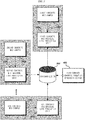
FIG. 2 is a diagram showing a configuration of a system for predicting a residual lifespan of a fire-damaged concrete structure according to an exemplary embodiment of the present invention. -
FIG. 3 is a diagram exemplifying a standardized database (DB) constructed by a system for predicting a residual lifespan of a fire-damaged concrete structure according to an exemplary embodiment of the present invention. -
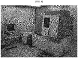
FIG. 4 is a diagram exemplifying an x-ray diffraction (XRD) analysis device for chemical analysis in a system for predicting a residual lifespan of a fire-damaged concrete structure according to an exemplary embodiment of the present invention. -
FIGS. 5A to 5C are diagrams exemplifying XRD analysis results for a concrete structure. -
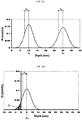
FIG. 6A is a diagram showing a pore distribution of pore size according to a heating temperature, andFIG. 6B is a diagram showing a fine pore ratio according to the heating temperature. -
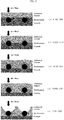
FIG. 7 is a diagram illustrating performance degradation of concrete caused by carbonation. -
FIG. 8A is a diagram showing probability distributions of carbonation depth and cover thickness, andFIG. 8B is a diagram showing a probability distribution of a limit state function. -
FIG. 9 is a diagram exemplifying a residual lifespan of a concrete structure in a limit state. -
FIG. 10 is an operational flowchart illustrating a method of predicting a residual lifespan of a fire-damaged concrete structure according to an exemplary embodiment of the present invention. -
FIG. 11 is a detailed operational flowchart illustrating a method of predicting a residual lifespan of a fire-damaged concrete structure according to an exemplary embodiment of the present invention. - Hereinafter, exemplary embodiments of the present invention will be described in detail with reference to the accompanying drawings so that those of ordinary skill in the art to which the present invention pertains can implement the present invention. However, the present invention can be embodied in various different forms and is not limited to embodiments described herein. To clearly describe the present invention, parts which are not related to description will be omitted from the drawings, and like parts are denoted by like reference numerals in this specification.
- Throughout this specification, when a certain part "includes" a certain component, the description means that another component may be further included and does not exclude another component unless particularly stated otherwise. Further, terms, such as "... unit" and the like used in this specification refer to a unit for processing at least one function or operation and may be implemented by hardware, software, or a combination thereof.
-
FIG. 2 is a diagram showing a configuration of a system for predicting a residual lifespan of a fire-damaged concrete structure according to an exemplary embodiment of the present invention, andFIG. 3 is a diagram exemplifying a standardized database (DB) constructed by a system for predicting a residual lifespan of a fire-damaged concrete structure according to an exemplary embodiment of the present invention. - Referring to
FIGS. 2 and3 , a system for predicting a residual lifespan of a fire-damaged concrete structure according to an exemplary embodiment of the present invention generally includes a fire-damagedconcrete structure sample 100, a concrete structure residuallifespan prediction unit 200, astandardized DB 300, and a fire-damaged concretestructure diagnosis device 400, and the concrete structure residuallifespan prediction unit 200 includes achemical analysis unit 210, adata analysis unit 220, and a fire damage diagnosis and residuallifespan assessment unit 230. - The fire-damaged
concrete structure sample 100 is collected from a fire-damaged concrete structure by, for example, drilling into the concrete structure to a target point using a mobile core drill, and is precisely processed. Here, thesample 100 may have various sizes, and a preferable size is a diameter of 10 mm x a length of 40 mm. Also, the collected fire-damagedconcrete structure sample 100 is precisely cut using a laser cutter or the like. For example, the collected fire-damagedconcrete structure sample 100 may be cut into various sizes, and a total of four samples may be prepared according to depths by cutting the fire-damaged concrete structure by 10 mm each time. Each of the four fire-damagedconcrete structure samples 100 is finely ground using an agate mortar set or the like to be processed into a specimen for chemical analysis. Here, the agate mortar set refers to a hand mill which is made from agate and used to break a solid mineral specimen in a laboratory. - The concrete structure residual
lifespan prediction unit 200 acquires sample data by performing a chemical analysis on the fire-damagedconcrete structure samples 100 which have been processed into specimens for chemical analysis, and separately predicts a fire damage temperature, a pore structure, and a carbonation depth by comparing the acquired sample data with data pre-stored in thestandardized DB 300 to diagnose fire damage to the fire-damagedconcrete structure samples 100 and assess a residual lifespan thereof. - Specifically, the
chemical analysis unit 210 of the concrete structure residuallifespan prediction unit 200 performs a chemical analysis on the fire-damagedconcrete structure samples 100 which have been processed into the specimens for chemical analysis and acquires sample data. - The
data analysis unit 220 of the concrete structure residuallifespan prediction unit 200 compares the sample data acquired by thechemical analysis unit 210 with the data pre-stored in thestandardized DB 300 to separately predict a fire damage temperature, a pore structure, and a carbonation depth. - Here, the
data analysis unit 220 may include a fire damagetemperature prediction unit 221, a porestructure prediction unit 222, and a carbonationdepth prediction unit 223. Specifically, the fire damagetemperature prediction unit 221 of thedata analysis unit 220 compares the sample data acquired by thechemical analysis unit 210 with data pre-stored in adamaging temperature DB 310 of thestandardized DB 300 and predicts the fire damage temperature. The porestructure prediction unit 222 of thedata analysis unit 220 compares the sample data with data pre-stored in a temperature-specificpore structure DB 320 of thestandardized DB 300 and predicts temperature-specific pore structures. The carbonationdepth prediction unit 223 of thedata analysis unit 220 compares the sample data with data pre-stored in a pore structure-specificcarbonation depth DB 330 of thestandardized DB 300 and predicts the carbonation depth. - The fire damage diagnosis and residual
lifespan assessment unit 230 of the concrete structure residuallifespan prediction unit 200 diagnoses fire damage to the fire-damagedconcrete structure samples 100 and assesses a residual lifespan according to the fire damage temperature, the pore structures, and the carbonation depth analyzed by thedata analysis unit 220. - The
standardized DB 300 standardizes and stores experimental data acquired through precise experimentation employing the fire-damaged concretestructure diagnosis device 400, and the experimental data is used as comparative data for the sample data acquired by thechemical analysis unit 210. Such a data comparison method is similar to, for example, a method of finding an element name using existing data when analyzing an unknown element. Thestandardized DB 300 according to an exemplary embodiment of the present invention includes thedamaging temperature DB 310, the temperature-specificpore structure DB 320, and the pore structure-specificcarbonation depth DB 330. - The
damaging temperature DB 310 of thestandardized DB 300 stores real-time chemical property change data according to a fire damage temperature acquired through a chemical analysis, such as an x-ray diffraction (XRD) analysis or the like, of the fire-damaged concrete structure. - The temperature-specific
pore structure DB 320 of thestandardized DB 300 stores pore structure characteristic change data according to a fire damage temperature acquired through a pore volume analysis device, such as a Brunauer-Emmett-Teller (BET) analysis or the like, of the fire-damaged concrete structure. - The pore structure-specific
carbonation depth DB 330 of thestandardized DB 300 stores carbonation depth data according to a change in pore structure acquired through an accelerated carbonation analysis of the fire-damaged concrete structure. - For the XRD analysis, the BET analysis, and the accelerated carbonation analysis, the fire-damaged concrete
structure diagnosis device 400 may make a total of 20 measurements by making one measurement every time a heating temperature of a concrete structure specimen increases by 50 °C, and then store each piece of data to construct thestandardized DB 300. At this time, as a common test condition for the XRD analysis, the BET analysis, and the accelerated carbonation analysis, the specimen is heated from 20 °C to 1000 °C, and results are analyzed and stored. Here, an XRD device, a BET device, and an accelerated carbonation test device used to analyze a chemical property change, a pore structure characteristic change, and a carbonation depth change are arbitrary examples of analysis equipment, and the analyses may be performed by other equipment. For example, the chemical property change may be analyzed by inductively coupled plasma, and a pore structure characteristic may be analyzed by porosimetry. - Meanwhile, as shown in
FIG. 3 , the fire-damaged concretestructure diagnosis device 400 may perform the XRD analysis, the BET analysis, and the accelerated carbonation analysis and store data acquired therefrom in thestandardized DB 300, and thestandardized DB 300 may be provided in common to a plurality of terminals with which the system for predicting a residual lifespan of a fire-damaged concrete structure according to an exemplary embodiment of the present invention is constructed through a web, a digital card, or the like. - For example, Korean ready-mixed concrete manufacturers produce various types of concrete according to mixing conditions and deliver the produced concrete to sites. The
standardized DB 300 may be constructed by analyzing all types of mixing condition-specific ready-mixed concrete commonly used in Korea as described above, and it is possible to provide information for predicting residual lifespans of most fire-damaged Korean building structures through thestandardized DB 300. In other words, a first concrete mix residuallifespan prediction unit 200a may predict a residual lifespan of a fire-damaged concrete structure with respect to a firstconcrete mix sample 100a, a second concrete mix residuallifespan prediction unit 200b may predict a residual lifespan of the fire-damaged concrete structure with respect to a secondconcrete mix sample 100b, and an Nth concrete mix residuallifespan prediction unit 200n may predict a residual lifespan of the fire-damaged concrete structure with respect to an Nthconcrete mix sample 100n. - Meanwhile,
FIG. 4 is a diagram exemplifying an XRD analysis device for chemical analysis in a system for predicting a residual lifespan of a fire-damaged concrete structure according to an exemplary embodiment of the present invention, andFIGS. 5A to 5C are diagrams exemplifying XRD analysis results for a concrete structure. - The system for predicting a residual lifespan of a fire-damaged concrete structure according to an exemplary embodiment of the present invention performs a chemical analysis on a fire-damaged concrete structure using an XRD analysis device as shown in
FIG. 4 . - Specifically, an XRD analysis is a method of emitting x rays toward a surface of a concrete structure sample and then qualitatively and quantitatively identifying chemical constituents of the specimen by analyzing refraction angles of reflected x rays, and in the method, the concrete structure sample is milled into fine powder and chemically analyzed to identify chemical element symbols representing chemical constituents of the powdered sample. A reaction product analysis based on such XRD is an analysis method for easily identifying reaction products of minerals constituting all materials with no chemical analysis and is performed to estimate physical properties of a concrete structure and determine a reason for an abnormality in the physical properties of the concrete structure.
-
FIG. 5A is a diagram illustrating main peak indicators of hydration products and reaction products, andFIGS. 5B and5C show XRD analysis results of a reference specimen of a concrete structure. Here, concrete hydration involves calcium oxide reacting with water to form calcium hydroxide, and CSH gel, CH, and CS are main components of cement. Accordingly, an XRD analysis of concrete makes it possible to quantitatively estimate a change of cement hydrates in the concrete caused by a high temperature and estimate a fire temperature and a duration of the temperature. - Specifically, results of heating a specimen of a ferroconcrete structure having no fire damage, which is a reference specimen, to a range of 100 °C to 1,000 °C in an electric furnace are shown in
FIGS. 5B and5C . - According to analysis results, Ca(OH)2 existed at up to 400 °C. However, at 600 °C or above, a CH component mostly disappeared while a CaO component appeared and an amount thereof increased with the increase in temperature. This is because, as a temperature of concrete increases during a fire, calcium hydroxide is decomposed and calcite (CaCO3) is decomposed into CaO.
- When a surface portion of the specimen reached 800 °C, Ca(OH)2, which is a cement hydration product, and CaCO3, which is calcite, were completely decomposed, and peaks thereof disappeared, whereas a peak of Cao was remarkably formed. It can be seen that Ca(OH)2 was completely decomposed but CaCO3, which is calcite, existed through analysis. On the other hand, Ca(OH)2 was assessed as not being decomposed at all at 400 °C at an inner portion of the specimen.
- Therefore, for an XRD analysis test, the above-described fire-damaged concrete
structure diagnosis device 400 makes a total of 20 measurements by making one measurement every time the heating temperature of the concrete structure specimen increases by 50 °C, and then stores each piece of data to construct thedamaging temperature DB 310 of thestandardized DB 300. According to an exemplary embodiment of the present invention, a manufactured specimen is milled into fine powder and then subjected to an XRD analysis. In this way, reaction products of concrete are qualitatively analyzed, and how much and into which materials cement hydrates are changed by a high temperature is quantitatively analyzed so that it can be seen how concrete reacts according to temperatures of a fire and what kinds of products are generated. - Meanwhile, according to the BET analysis, a concrete structure sample is inserted into a sample tube, and then nitrogen gas is injected into the sample tube so that the nitrogen gas is adsorbed onto the specimen and desorbed therefrom, and a pore size distribution may be measured in this way. Such a BET analysis is used to measure pores with a relatively small radius.
- Specifically, a BET analysis method developed by Brunauer, Emmett, and Teller is typically used to measure a surface area of a porous adsorbate. Such a BET analysis method is a measurement method of identifying a monolayer adsorption point using a sorption isotherm and getting a surface area of a sample from the monolayer adsorption point. Such a BET analysis method is given as Equation 1 below by extending Langmuir's monolayer adsorption theory to a multi-layer adsorption theory using three assumptions, that is, (a) surface energy is uniform, (b) there are no interactions between adsorbed molecules, and (c) all adsorption temperatures of two or more layers are the same.

- Here, v denotes an adsorption amount under equilibrium pressure, v m denotes a monolayer adsorption amount, P denotes an adsorption equilibrium pressure, P 0 denotes a saturated vapor pressure, and P/P 0 denotes a relative pressure, and here C is given as C : e (q
l -qr )/RT . - Therefore, when the monolayer adsorption amount v m from a solid surface is known, a specific surface area S may be calculated using molecule-occupied sectional area adsorption (the area of nitrogen is 0.162 nm2) as shown in
Equation 2 below.
- Such nitrogen gas adsorption for measuring a pore structure of a concrete structure is based on a principle that since the relative pressure P/P 0 increases when gas is adsorbed onto a solid surface up to the saturated vapor pressure P 0, a monolayer further forms a multilayer, and capillary condensation as well as adsorption takes place in pores.
- Specifically, before such a gas adsorption measurement is made, a cell in which a concrete structure specimen is inserted is covered with a heating bag and subjected to vacuum drawing for preprocessing, liquid nitrogen is inserted in a dewar, and a small amount of adsorption gas is introduced into the specimen cell in stages. At this time, when the dewar filled with liquid nitrogen is placed on the specimen cell to cool the cell, introduced nitrogen gas is physically adsorbed. As a result, property values of a pore structure determined by such a nitrogen gas adsorption measurement may indicate the specific surface area S, a pore structure, and a pore distribution.
- Next, a change in pore structure according to a heating temperature for a concrete structure specimen will be described in detail below.
-
FIG. 6A is a diagram showing a pore distribution of pore size according to a heating temperature, and shows a distribution of pores having sizes of about 0.001 µm to about 0.1 µm according to an exposure temperature condition of a concrete structure using the aforementioned nitrogen gas adsorption. Here, it can be seen that, with an increase in heating temperature of each specimen, a pore volume of fine pores of 0.01 µm or less is reduced while a pore volume of pores of 0.01 µm or more increases. - With an increase in temperature up to 200 °C, free water, gel water, and capillary water in concrete evaporates so that the concrete shrinks, and an internal structure of a paste loosens so that a pore volume of fine pores (of about 0.01 µm or less) increases. However, at about 300 °C, a part of C-S-H interlayer water and chemically-bonded water of hydrates disappears. Also, in a range of 400 °C to 700 °C, since calcium hydroxide (Ca(OH)2) is decomposed, a dehydration volume increases due to an increase in temperature, and diameters of the fine pores (about 0.01 µm or less) increases so that the pore volume of the fine pores (about 0.01 µm or less) is reduced.
- Therefore, an overall tendency indicates that a pore volume is reduced in accordance with an increase in heating temperature within a range of the pore size (about 0.001 µm to about 0.1 µm) measured by the nitrogen gas adsorption.
-
FIG. 6B is a diagram showing a fine pore ratio according to a water-to-cement (W/C) change and a heating temperature condition, and shows a pore volume of fine pores of 0.1 µm or less which can be measured by nitrogen adsorption. As shown inFIG. 6B , the pores of 0.1 µm or less are very fine pores, and thus do not have a significant influence on an overall pore volume of concrete. However, it is judged that even when the fine pores of 0.1 µm or less are reduced, large pores of 0.1 µm or more are increased, and thus the overall pore volume of the concrete increases with an increase in heating temperature. Accordingly, such a change in pore volume results from a destruction of fine pores and a decomposition of calcium hydroxide caused by an increase in heating temperature and dehydration of the number of capillaries, the number of gels, and the like. - Consequently, according to an exemplary embodiment of the present invention, it is possible to see a heating temperature, that is, a pore size distribution according to a fire damage temperature, and for a BET analysis test, the above-described fire-damaged concrete
structure diagnosis device 400 may make a total of 20 measurements by making one measurement every time a heating temperature of a concrete structure specimen increases by 50 °C, and then store each piece of data to construct the temperature-specificpore structure DB 320 of thestandardized DB 300. - Meanwhile, an accelerated carbonation analysis is a method of inserting a sample into a chamber, introducing highly concentrated carbon dioxide into the chamber to promote a reaction, and then measuring a reaction depth between the introduced carbon dioxide and calcium hydroxide existing in the sample by cutting the sample. Using such a measured value, it is possible to determine a penetration depth of carbon dioxide and predict a durability life of concrete, that is, a residual lifespan of a fire-damaged concrete structure.
- Specifically, concrete carbonation is described as follows. Cement, which is a main material of ferroconcrete, is strongly alkaline with a pH of about 13 to about 15, and reinforcement bars existing in concrete are not corroded in a general environment. However, reinforcement bars in a concrete structure may be placed in a corrosive environment, i.e., carbonated by carbon dioxide in the air. In other words, output of carbon monoxide and dioxide is increasing in accordance with the recent growth of cities, and carbonation of major buildings is being accelerated thereby. In particular, a pore volume of concrete is closely related to a penetration rate of carbon dioxide, and thus works as the most crucial factor for determining a residual lifespan of a concrete structure.
- Reinforcement bars in concrete are covered with an oxide passivation film in an environment with a pH of 11 or more, and thus are not corroded even when there is oxygen in the concrete. However, when carbonation reaches the reinforcement bars and the pH drops below 11, the reinforcement bars are corroded. Here, a time for carbonation to reach the reinforcement bars is clearly in proportion to a pore volume of the concrete. When there is a high pore volume, a rate of reaching the reinforcement bars increases. Generally, a pore volume increases with an increase in W/C. However, a pore volume increases exponentially when concrete is put in a special situation, such as a fire, and a durability life of concrete is shortened due to carbonation.
-
FIG. 7 is a diagram illustrating performance degradation of concrete caused by carbonation. As shown in (a) ofFIG. 7 , in a first carbonation step, there is almost no change in materials and strength and there are only small cracks caused by drying shrinkage. As shown in (b) ofFIG. 7 , in a second carbonation step, inflation pressure is generated in concrete due to rust generation and cracks are generated. As shown in (c) ofFIG. 7 , in a third carbonation step, cement above reinforcement bars begin to expand and cracks extend to a surface of the concrete. Therefore, air and water penetration becomes severe and causes other deterioration, such as freezing damage and the like, and it is possible to see rusty water. As shown in (d) ofFIG. 7 , in a fourth carbonation step, a coating of the cement above the reinforcement bars is broken, the reinforcement bars begin to be exposed, and a sectional area is reduced. Finally, as shown in (e) ofFIG. 7 , in a fifth carbonation step, most of the cement above the reinforcement bars disappears and the reinforcement bars are exposed to the air and lose durability. - Such concrete carbonation begins with an outer portion of concrete exposed to carbon dioxide and gradually proceeds. However, carbon dioxide should be diffused through pores included in a concrete surface which has already been carbonated, and thus a carbonation rate is gradually reduced. Here, in an environment with uniform humidity, a carbonation depth increases in proportion to the square root of time. This is related to an interaction between carbon dioxide and a pore system, and a carbonation depth C can be expressed as shown in
Equation 3 below.
- The concrete carbonation rate is in proportion to the square root of time or in a like form. When the carbonation depth is C and a cover thickness is D, a safety margin of the cover thickness with respect to carbonation can be defined as M = D - C. Assuming that a time for the carbonation depth C to reach reinforcement bars is a lifespan with respect to carbonation, the safety margin denotes a limit state with respect to carbonation in which M is a limit. Therefore, a time for a carbonation depth of a concrete structure to reach reinforcement bars thereof may be a durability life of the structure with respect to carbonation, and it is possible to obtain a residual lifespan of the structure by excluding a measurement time. A limit state function can be expressed by
Equation 4.
- Here, M(x, t) denotes a limit state with respect to carbonation, D(x, t) denotes a carbonation depth, and C(x, t) denotes a cover thickness.
- Also, since carbonation depth data obtained through precise safety diagnosis of a concrete structure may be considered to be a probability distribution of each section, it is possible to calculate probabilistic characteristic values, such as an average, a standard deviation, etc., of each of the sections by analyzing measured section-specific carbonation depth data. In the same way, since a distribution cover thickness value may also be considered to be a random variable in the same section due to errors in design and construction, it is possible to calculate an average and a standard deviation by analyzing measured cover thickness data.
-
FIG. 8A is a diagram showing probability distributions of the carbonation depth C and the cover thickness D, andFIG. 8B is a diagram showing a probability distribution of a limit state function M with respect to carbonation. Here, each curve denotes a probability density function. - Specifically, assuming that an average and a standard deviation of the carbonation depth C are respectively µc and σc , an average and a standard deviation of the cover thickness D are respectively µd and σd , and distributions of the carbonation depth and the cover thickness are normal distributions, the limit state function M with respect to carbonation also becomes a normal distribution. Here, an average and a standard deviation of the limit state function are respectively given by
Equations 5 and 6 below.

- As shown in
FIG. 8B , a cumulative distribution function of 0 or less, that is, pf , can be referred to as a probability that a carbonation depth increases to a cover thickness and reaches reinforcement bars. - Here, pf is a value calculated by probabilistically approaching a distribution of a cover thickness as well as a carbonation depth, or a progress tendency of carbonation. Therefore, a total lifespan and a residual lifespan of a structure based on such a residual lifespan assessment model are obtained through statistical inference.
-
FIG. 9 is a diagram exemplifying a residual lifespan of a concrete structure in a limit state, and a limit of pf may have a range of 0 to 1. For example, to obtain a conservative assessment value, a time for pf to become 0.5 may be a residual lifespan of a concrete structure as shown inFIG. 9 . - Therefore, for an accelerated carbonation analysis test, the above-described fire-damaged concrete
structure diagnosis device 400 makes a total of 20 measurements by making one measurement every time a heating temperature of a concrete structure specimen increases by 50 °C, and then stores each piece of data to construct the pore structure-specificcarbonation depth DB 330 of thestandardized DB 300. - According to an exemplary embodiment of the present invention, it is possible to acquire sample data by performing a chemical analysis on a sample of a fire-damaged concrete structure, and to rapidly predict a residual lifespan of the fire-damaged concrete structure by comparing the acquired sample data with data pre-stored in a standardized DB.
- According to an exemplary embodiment of the present invention, since it is possible to accurately and scientifically assess a level of fire damage, appropriate repair and reinforcement can be made. In other words, it is possible to improve performance of a fire-damaged concrete structure by predicting a residual lifespan of the concrete structure and managing the concrete structure by considering of appropriate repair and reinforcement times.
-
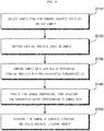
FIG. 10 is an operational flowchart illustrating a method of predicting a residual lifespan of a fire-damaged concrete structure according to an exemplary embodiment of the present invention. - Referring to
FIG. 10 , the method of predicting a residual lifespan of a fire-damaged concrete structure according to an exemplary embodiment of the present invention first involves collecting thesample 100 from a fire-damaged concrete structure and precisely cutting the sample 100 (S110). Here, thesample 100 is collected by drilling into the concrete structure to a target point using a mobile core drill, is precisely processed, and then is finely ground using an agate mortar set to be processed into a specimen for chemical analysis. - Next, a chemical (XRD) analysis is performed on the precisely cut sample 100 (S120). Subsequently, data of the chemical analysis is used as initial input data.
- Next, the sample data on which the chemical analysis is performed is compared with the pre-constructed standardized DB 300 (S130). Here, the
standardized DB 300 standardizes experimental data acquired through precise experimentation employing the fire-damaged concretestructure diagnosis device 400 and stores the standardized experimental data. For XRD analysis, BET analysis, or carbonation analysis, the fire-damaged concretestructure diagnosis device 400 makes a total of 20 measurements by making one measurement every time a heating temperature of the concrete structure specimen increases by 50 °C, and then stores each piece of data to construct thestandardized DB 300. - Next, a fire damage temperature, a pore structure, and a carbonation depth corresponding to the sample data are predicted (S140).
- Next, fire damage to the concrete structure is diagnosed and a residual lifespan thereof is assessed (S150).
-
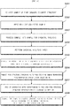
FIG. 11 is a detailed operational flowchart illustrating a method of predicting a residual lifespan of a fire-damaged concrete structure according to an exemplary embodiment of the present invention. - Referring to
FIG. 11 , the method of predicting a residual lifespan of a fire-damaged concrete structure according to an exemplary embodiment of the present invention first involves collecting thesample 100 from a fire-damaged concrete structure (S201). Specifically, a sample of the fire-damaged concrete structure is collected in an inward direction from a surface thereof. For example, the concrete structure is drilled to a target point using a mobile core drill. Here, thesample 100 may have various sizes, and a preferable size is a diameter of 10 mm × a length of 40 mm. - Next, the collected
sample 100 is precisely cut using a laser cutter or the like (S202). For example, the collectedsample 100 may be cut in various sizes, and a total of four samples may be prepared according to depths by cutting the fire-damaged concrete structure by 10 mm each time. - Next, the four
samples 100 are processed into samples for chemical analysis (S203). Specifically, each of the foursamples 100 is processed into a specimen for chemical analysis. At this time, each of the foursamples 100 is finely ground using an agate mortar set or the like. Here, the agate mortar set refers to a hand mill which is made from agate and used to break a solid mineral specimen in a laboratory. - Next, a chemical analysis, for example, XRD, is performed on the specimens for chemical analysis (S204).
- Next, data of the chemically-analyzed
samples 100 is compared with data stored in thedamaging temperature DB 310 in thestandardized DB 300 to predict fire damage temperatures thereof (S205). In other words, the data of the chemically-analyzedsamples 100 and the data stored in thedamaging temperature DB 310 are compared to find temperatures in data of the chemically-analyzedsamples 100 which coincide with the data obtained from thedamaging temperature DB 310 so that fire damage temperatures of thesamples 100 is predicted. - Next, pore structures corresponding to the predicted fire damage temperatures are predicted from the temperature-specific
pore structure DB 320 in the standardized DB 300 (S206). In other words, pore structures at the predicted fire damage temperatures which coincide with data obtained from the temperature-specificpore structure DB 320 are found to predict pore structures of thesamples 100. - Next, carbonation depths corresponding to the predicted pore structures are predicted from the pore structure-specific
carbonation depth DB 330 in the standardized DB 300 (S207). In other words, carbonation depths of the predicted pore structures which coincide with data obtained from the pore structure-specificcarbonation depth DB 330 are found. - Next, according to the fire damage temperatures, the pore structures, and the carbonation depths of the
samples 100, fire damage to the concrete structure is diagnosed and a residual lifespan thereof is assessed (S208). Since those of ordinary skill in the art should appreciate that it is possible to diagnose the fire damage and assess the residual lifespan according to a change in chemical components, a change in pore structures, and a progress of carbonation, a detailed description thereof will be omitted. - Accordingly, each of the
damaging temperature DB 310, the temperature-specificpore structure DB 320, and the pore structure-specificcarbonation depth DB 330 in thestandardized DB 300 can easily manage information on a change in chemical components, a change in pore structures, and a progress of carbonation according to a change in a temperature of a fire-damaged concrete structure. In other words, using data matching analysis, it is possible to extract data which coincides with data measured through external experimentation and rapidly predict a fire damage temperature, a change in pore volume, and a change in residual lifespan of a fire-damaged concrete structure. - The above descriptions of the present invention are exemplary, and those of ordinary skill in the art to which the present invention pertains should understand that various modifications can be made without departing from the technical spirit or essential characteristics of the present invention. Therefore, it should be understood that the embodiments described above are exemplary in all aspects and are not restrictive. For example, each component which is described in a single form may be implemented in a distributed manner, and similarly, components which are described as being distributed may be implemented in a combined form.
- The scope of the present invention is represented by the claims to be described below rather than the detailed descriptions, and the meaning and the scope of the claims and all changed or modified forms derived from the equivalent concept thereof should be interpreted as being included in the scope of the present invention.
-
- 100: fire-damaged concrete structure sample
- 200: concrete structure residual lifespan prediction unit
- 300: standardized DB
- 400: fire-damaged concrete structure diagnosis device
- 210: chemical analysis unit
- 220: data analysis unit
- 221: fire damage temperature prediction unit
- 222: pore structure prediction unit
- 223: carbonation depth prediction unit
- 230: fire damage diagnosis and residual-lifespan assessment unit
- 310: damaging temperature DB
- 320: temperature-specific pore structure DB
- 330: pore structure-specific carbonation depth DB
Claims (10)
- A system for predicting a residual lifespan of a fire-damaged concrete structure, the system comprising:a fire-damaged concrete structure sample (100) collected from a fire-damaged concrete structure and processed into a specimen for chemical analysis;a concrete structure residual lifespan prediction unit (200) configured to obtain sample data by performing a chemical analysis on the fire-damaged concrete structure sample (100) processed into the specimen for chemical analysis, diagnose fire damage to the fire-damaged concrete structure by comparing the sample data with data pre-stored in a standardized database (DB) (300), and assess a residual lifespan of the fire-damaged concrete structure; andthe standardized DB (300) constructed by storing data acquired through experimentation to be compared with the sample data of the chemical analysis performed by the concrete structure residual lifespan prediction unit (200),wherein the standardized DB (300) standardizes and stores experimental data acquired through precise experimentation employing a fire-damaged concrete structure diagnosis device (400).
- The system of claim 1, wherein, for an x-ray diffraction (XRD) analysis, a Brunauer-Emmett-Teller (BET) analysis, and an accelerated carbonation analysis test, the fire-damaged concrete structure diagnosis device (400) makes a total of 20 measurements by making one measurement every time a heating temperature of a concrete structure specimen increases by 50 °C, and then stores each piece of data to construct the standardized DB (300).
- The system of claim 1, wherein the fire-damaged concrete structure sample (100) is collected by drilling into the concrete structure to a target point using a mobile core drill, is precisely processed, and is then finely ground using an agate mortar set to be processed into the specimen for chemical analysis.
- The system of claim 1, wherein the concrete structure residual lifespan prediction unit (200) comprises:a chemical analysis unit (210) configured to acquire the sample data by performing the chemical analysis on the fire-damaged concrete structure sample (100) processed into the specimen for chemical analysis;a data analysis unit (220) configured to separately predict a fire damage temperature, a pore structure, and a carbonation depth by comparing the sample data acquired by the chemical analysis unit (210) with the data pre-stored in the standardized DB (300); anda fire damage diagnosis and residual-lifespan assessment unit (230) configured to diagnose fire damage of the fire-damaged concrete structure sample (100) according to the fire damage temperature, the pore structure, and the carbonation depth analyzed by the data analysis unit (220) and assess the residual lifespan thereof.
- The system of claim 4, wherein the data analysis unit (220) comprises:a fire damage temperature prediction unit (221) configured to predict the fire damage temperature by comparing the sample data acquired by the chemical analysis unit (210) with damaging temperature data pre-stored in the standardized DB (300);a pore structure prediction unit (222) configured to predict temperature-specific pore structures by comparing the sample data acquired by the chemical analysis unit (210) with temperature-specific pore structure data pre-stored in the standardized DB (300); anda carbonation depth prediction unit (223) configured to identify a change in durability by comparing the sample data acquired by the chemical analysis unit (210) with pore structure-specific carbonation depth data pre-stored in the standardized DB (300).
- The system of claim 1, wherein the standardized DB (300) comprises:a damaging temperature DB (310) configured to store real-time chemical property change data in accordance with a fire damage temperature and acquired through an x-ray diffraction (XRD) analysis of the fire-damaged concrete structure;a temperature-specific pore structure DB (320) configured to store pore structure characteristic change data in accordance with a fire damage temperature and acquired through a Brunauer-Emmett-Teller (BET) analysis of the fire-damaged concrete structure; anda pore structure-specific carbonation depth DB (330) configured to store carbonation depth data in accordance with a change in pore structure and acquired through a carbonation analysis of the fire-damaged concrete structure.
- A method of predicting a residual lifespan of a fire-damaged concrete structure, the method comprising:a) collecting a sample (100) from a fire-damaged concrete structure and precisely cutting the sample (100);b) performing a chemical (x-ray diffraction (XRD)) analysis on the precisely cut sample (100);c) comparing sample data obtained by performing the chemical analysis with data stored in a pre-constructed standardized database (DB) (300);d) separately predicting a fire damage temperature, a pore structure, and a carbonation depth corresponding to the sample data from the standardized DB (300); ande) diagnosing fire damage to the fire-damaged concrete structure and assessing a residual lifespan thereof according to the fire damage temperature, the pore structure, and the carbonation depth,wherein the standardized DB (300) standardizes and stores experimental data acquired through precise experimentation employing a fire-damaged concrete structure diagnosis device (400).
- The method of claim 7, wherein, for the XRD analysis, a Brunauer-Emmett-Teller (BET) analysis, and an accelerated carbonation analysis test, the fire-damaged concrete structure diagnosis device (400) makes a total of 20 measurements by making one measurement every time a heating temperature of a concrete structure specimen increases by 50 °C, and then stores each piece of data to construct the standardized DB (300).
- The method of claim 7, wherein the sample (100) of step a) is collected by drilling into the concrete structure to a target point using a mobile core drill, is precisely processed, and then is finely ground using an agate mortar set to be processed into a specimen for chemical analysis.
- The method of claim 7, wherein the standardized DB (300) of step c) comprises:a damaging temperature DB (310) configured to store real-time chemical property change data in accordance with a fire damage temperature and acquired through an XRD analysis of the fire-damaged concrete structure;a temperature-specific pore structure DB (320) configured to store pore structure characteristic change data in accordance with a fire damage temperature and acquired through a Brunauer-Emmett-Teller (BET) analysis of the fire-damaged concrete structure; anda pore structure-specific carbonation depth DB (330) configured to store carbonation depth data in accordance with a change in pore structure and acquired through a carbonation analysis of the fire-damaged concrete structure.
Applications Claiming Priority (2)
| Application Number | Priority Date | Filing Date | Title |
|---|---|---|---|
| KR1020140184431A KR101554165B1 (en) | 2014-12-19 | 2014-12-19 | System for predicting residual service life of fire-damaged concrete structures, and method for the same |
| PCT/KR2015/011402 WO2016099027A1 (en) | 2014-12-19 | 2015-10-28 | System for predicting residual lifespan of fire-damaged concrete structure and method therefor |
Publications (3)
| Publication Number | Publication Date |
|---|---|
| EP3236409A1 true EP3236409A1 (en) | 2017-10-25 |
| EP3236409A4 EP3236409A4 (en) | 2018-08-15 |
| EP3236409B1 EP3236409B1 (en) | 2019-07-31 |
Family
ID=54248633
Family Applications (1)
| Application Number | Title | Priority Date | Filing Date |
|---|---|---|---|
| EP15870195.3A Active EP3236409B1 (en) | 2014-12-19 | 2015-10-28 | System for predicting residual lifespan of fire-damaged concrete structure and method therefor |
Country Status (6)
| Country | Link |
|---|---|
| US (1) | US10495625B2 (en) |
| EP (1) | EP3236409B1 (en) |
| KR (1) | KR101554165B1 (en) |
| CN (1) | CN107111793B (en) |
| DK (1) | DK3236409T3 (en) |
| WO (1) | WO2016099027A1 (en) |
Families Citing this family (18)
| Publication number | Priority date | Publication date | Assignee | Title |
|---|---|---|---|---|
| KR102020268B1 (en) | 2017-09-04 | 2019-09-10 | 대구대학교 산학협력단 | Fire temperature detection indicator and structure damage degree and range assessment method with its use |
| CN107941645B (en) * | 2017-12-15 | 2020-04-14 | 东南大学 | Method for measuring reaction degree of each substance in fly ash, silica fume and cement three-phase composite system |
| CN108920865A (en) * | 2018-07-20 | 2018-11-30 | 广东工业大学 | A kind of damage concrete structure restorative procedure, system and equipment and storage medium |
| CN108918583A (en) * | 2018-07-23 | 2018-11-30 | 广东工业大学 | A kind of restorative procedure, device and storage medium for Concrete after Fire |
| KR102187176B1 (en) * | 2019-01-28 | 2020-12-04 | 강원대학교산학협력단 | Method For Providing Reinforced Concrete Service Life Considering Climate Change and Crack Effect And Recording Medium Thereof |
| KR102256239B1 (en) | 2019-09-25 | 2021-05-27 | 한국건설기술연구원 | Deep learning-based system for predicting 3d thermal diffusivity into concrete structures after fire, and method for the same |
| KR102107098B1 (en) | 2019-09-25 | 2020-05-28 | 한국건설기술연구원 | System for physical rehabilitation of fire-damaged concrete structure, and method for the same |
| CN110627437A (en) * | 2019-09-27 | 2019-12-31 | 赵之祯 | Concrete formula system for repairing cultural relic buildings and using method thereof |
| CN111077065B (en) * | 2019-12-30 | 2022-10-18 | 广东交科检测有限公司 | Method for measuring damaged depth of concrete after high temperature through grouped compression resistance of core samples |
| CN111488698B (en) * | 2020-04-21 | 2023-04-07 | 浙江水利水电学院 | Multi-scale prediction method for thermal expansion coefficient of hardened concrete |
| CN111898318A (en) * | 2020-08-04 | 2020-11-06 | 西安建筑科技大学 | Industrial building concrete carbonization depth prediction method |
| WO2022118731A1 (en) * | 2020-12-03 | 2022-06-09 | 株式会社フジタ | Method for fixing carbon dioxide to concrete, and concrete structure including concrete |
| CN112444534B (en) * | 2020-12-11 | 2021-12-28 | 中国地质大学(北京) | Method for rapidly measuring and calculating fire passing temperature of stone cultural relics |
| KR102210418B1 (en) | 2020-12-18 | 2021-02-02 | 한국건설기술연구원 | System for predicting residual stress distribution of fire-damaged concrete structure, and method for the same |
| KR102256243B1 (en) | 2020-12-21 | 2021-05-27 | 한국건설기술연구원 | Deep learning-based system for time-dependent assessment of concrete deterioration |
| US20230400449A1 (en) * | 2022-06-14 | 2023-12-14 | Halliburton Energy Services, Inc. | Method To Tailor Cement Composition To Withstand Carbon Dioxide Injection Loads |
| CN115186515B (en) * | 2022-08-26 | 2023-07-04 | 中国长江三峡集团有限公司 | Concrete drainage pipeline residual life prediction method and device |
| KR102586791B1 (en) | 2022-10-05 | 2023-10-10 | 주식회사 평안화재복구 | Fire Damaged Concrete Structure Recovery System |
Family Cites Families (24)
| Publication number | Priority date | Publication date | Assignee | Title |
|---|---|---|---|---|
| US6959270B2 (en) * | 2001-05-24 | 2005-10-25 | UNIVERSITé LAVAL | Method for modeling the transport of ions in hydrated cement systems |
| US6860932B2 (en) * | 2002-09-12 | 2005-03-01 | Yoshiki Oshida | Dental and medical cement |
| JP2005227065A (en) | 2004-02-12 | 2005-08-25 | Hitachi Ltd | Display method for estimated life duration of structure, method of creating life duration distribution, and image display |
| KR20060017666A (en) | 2005-11-30 | 2006-02-24 | 김영래 | Fatigue measurement device for structure and method thereof |
| KR100631485B1 (en) | 2006-03-27 | 2006-10-09 | 세기하이테크건설 주식회사 | Fast curing coating layer formation method for enhanced durability and preventing neutralization and salt damage of concrete structure and steel structure |
| KR100835848B1 (en) | 2006-04-19 | 2008-06-05 | 한국시설안전공단 | Automatic analysis method for the strength of the shotcrete lining under construction and the deteriorated concrete with aging |
| KR100894084B1 (en) | 2007-10-12 | 2009-04-21 | 연세대학교 산학협력단 | Distinction method for composition in concrete |
| KR100929416B1 (en) * | 2007-10-15 | 2009-12-03 | 삼성물산 주식회사 | Fire resistance evaluation system for high strength concrete members |
| JP2010032318A (en) * | 2008-07-28 | 2010-02-12 | Clion Co Ltd | Deterioration diagnosis method of autoclaved lightweight concrete panel |
| CN201387424Y (en) * | 2009-04-23 | 2010-01-20 | 中南林业科技大学 | Intelligent ultrasonic test device for concrete fire disaster damage characters |
| KR101128455B1 (en) | 2010-08-13 | 2012-03-23 | 한국건설기술연구원 | Method for measuring degree of hydration in concrete using backscattered electron imaging |
| EP2693186A4 (en) * | 2011-03-31 | 2014-11-26 | Nat Univ Corp Yokohama Nat Uni | Water absorption test method and water absorption test device for concrete surface |
| US20130131999A1 (en) | 2011-11-23 | 2013-05-23 | King Saud University | Method for predicting chloride-induced corrosion |
| CN104350021B (en) * | 2012-05-30 | 2017-03-01 | 太平洋水泥株式会社 | The quality of cement or the Forecasting Methodology of manufacturing condition |
| JP6042111B2 (en) | 2012-06-25 | 2016-12-14 | 大和ハウス工業株式会社 | Deterioration diagnosis method and diagnosis system for building |
| KR101263371B1 (en) * | 2012-09-28 | 2013-05-21 | 한국건설기술연구원 | Design method of fire resistance rating for concrete structure and concrete structure therewith |
| US9638652B2 (en) * | 2013-01-30 | 2017-05-02 | Giatec Scientific Inc. | Electrical methods and systems for concrete testing |
| CA2900049C (en) * | 2013-02-04 | 2020-08-18 | Coldcrete, Inc. | System and method of applying carbon dioxide during the production of concrete |
| CA2839056C (en) | 2013-03-01 | 2016-10-11 | Simco Technologies Inc. | Method and system for planning maintenance activities for concrete structures |
| US9388072B2 (en) * | 2013-06-25 | 2016-07-12 | Carboncure Technologies Inc. | Methods and compositions for concrete production |
| US20160107939A1 (en) * | 2014-04-09 | 2016-04-21 | Carboncure Technologies Inc. | Methods and compositions for concrete production |
| US20150193881A1 (en) * | 2014-01-03 | 2015-07-09 | BuildFax | Computer-implemented method for determining roof age of a structure |
| CN103938883A (en) * | 2014-03-13 | 2014-07-23 | 华南理工大学 | Re-alkalization repair method for concrete structure after high temperature fire |
| US20160075603A1 (en) * | 2014-09-16 | 2016-03-17 | Arizona Science And Technology Enterprises, Llc | Binder Compositions and Method of Synthesis |
-
2014
- 2014-12-19 KR KR1020140184431A patent/KR101554165B1/en active IP Right Grant
-
2015
- 2015-10-28 WO PCT/KR2015/011402 patent/WO2016099027A1/en active Application Filing
- 2015-10-28 CN CN201580068902.1A patent/CN107111793B/en active Active
- 2015-10-28 US US15/537,435 patent/US10495625B2/en active Active
- 2015-10-28 DK DK15870195.3T patent/DK3236409T3/en active
- 2015-10-28 EP EP15870195.3A patent/EP3236409B1/en active Active
Also Published As
| Publication number | Publication date |
|---|---|
| WO2016099027A1 (en) | 2016-06-23 |
| CN107111793B (en) | 2021-08-17 |
| DK3236409T3 (en) | 2019-08-12 |
| US20170350872A1 (en) | 2017-12-07 |
| US10495625B2 (en) | 2019-12-03 |
| KR101554165B1 (en) | 2015-09-21 |
| CN107111793A (en) | 2017-08-29 |
| EP3236409B1 (en) | 2019-07-31 |
| EP3236409A4 (en) | 2018-08-15 |
Similar Documents
| Publication | Publication Date | Title |
|---|---|---|
| EP3236409B1 (en) | System for predicting residual lifespan of fire-damaged concrete structure and method therefor | |
| EP4276674A1 (en) | Deep-learning-based concrete structure deterioration assessment system and method therefor | |
| JP5880981B2 (en) | Water absorption test method and apparatus for concrete surface | |
| Jiang et al. | Influence of chloride salt type on threshold level of reinforcement corrosion in simulated concrete pore solutions | |
| Diederichs et al. | Practical rock spall prediction in tunnels | |
| Paul et al. | Crack formation and chloride induced corrosion in reinforced strain hardening cement-based composite (R/SHCC) | |
| Wawrzeńczyk et al. | Evaluation of concrete resistance to freeze-thaw based on probabilistic analysis of damage | |
| Cheng et al. | Research on the interface structure during unidirectional corrosion for oil-well cement in H2S based on computed tomography technology | |
| Gao et al. | A pore size distribution-based microscopic model for evaluating the permeability of clay | |
| CN114722650A (en) | Tunnel structure residual life prediction method based on lining degradation | |
| KR102256239B1 (en) | Deep learning-based system for predicting 3d thermal diffusivity into concrete structures after fire, and method for the same | |
| Nordström et al. | Structural safey of cracked concrete dams | |
| Orsanic | Chemo-hygro-thermo-mechanical model for simulation of corrosion induced damage in reinforced concrete | |
| Andrade et al. | Evolution of corrosion parameters in a buried pilot nuclear waste container in el Cabril | |
| Ikotun | Effects of concrete quality and cover depth on carbonation-induced reinforcement corrosion and initiation of concrete cover cracking in reinforced concrete structures | |
| Petersen et al. | Proposal of a method for service life prediction of a concrete structure: a case study | |
| Duchesne et al. | Study of the deterioration of concrete incorporating sulfide-bearing aggregates | |
| Thiel et al. | Compliance testing for probabilistic durability design purposes | |
| Anand et al. | Condition assessment and analysis of a reinforced concrete building in India: a case study | |
| Folić et al. | Effects of carbonation and chloride ingress on the durability of concrete structures | |
| Di Benedetti | Acoustic emission in structural health monitoring of reinforced concrete structures | |
| Berkas et al. | Damage-reliability approach for fatigue crack propagation in MDPE gas pipe | |
| Adesina | Influence of Moisture on Alkali Silica Reaction | |
| Mamun | The Fractal Nature of Cement-Based Systems Under Sustained Elevated Temperatures | |
| Bungey | Assessment of concrete in bridge structures |
Legal Events
| Date | Code | Title | Description |
|---|---|---|---|
| STAA | Information on the status of an ep patent application or granted ep patent |
Free format text: STATUS: THE INTERNATIONAL PUBLICATION HAS BEEN MADE |
|
| PUAI | Public reference made under article 153(3) epc to a published international application that has entered the european phase |
Free format text: ORIGINAL CODE: 0009012 |
|
| STAA | Information on the status of an ep patent application or granted ep patent |
Free format text: STATUS: REQUEST FOR EXAMINATION WAS MADE |
|
| 17P | Request for examination filed |
Effective date: 20170706 |
|
| AK | Designated contracting states |
Kind code of ref document: A1 Designated state(s): AL AT BE BG CH CY CZ DE DK EE ES FI FR GB GR HR HU IE IS IT LI LT LU LV MC MK MT NL NO PL PT RO RS SE SI SK SM TR |
|
| AX | Request for extension of the european patent |
Extension state: BA ME |
|
| DAV | Request for validation of the european patent (deleted) | ||
| DAX | Request for extension of the european patent (deleted) | ||
| A4 | Supplementary search report drawn up and despatched |
Effective date: 20180716 |
|
| RIC1 | Information provided on ipc code assigned before grant |
Ipc: G06Q 50/08 20120101ALI20180710BHEP Ipc: G06Q 50/10 20120101AFI20180710BHEP |
|
| GRAP | Despatch of communication of intention to grant a patent |
Free format text: ORIGINAL CODE: EPIDOSNIGR1 |
|
| STAA | Information on the status of an ep patent application or granted ep patent |
Free format text: STATUS: GRANT OF PATENT IS INTENDED |
|
| INTG | Intention to grant announced |
Effective date: 20190308 |
|
| GRAS | Grant fee paid |
Free format text: ORIGINAL CODE: EPIDOSNIGR3 |
|
| GRAA | (expected) grant |
Free format text: ORIGINAL CODE: 0009210 |
|
| STAA | Information on the status of an ep patent application or granted ep patent |
Free format text: STATUS: THE PATENT HAS BEEN GRANTED |
|
| AK | Designated contracting states |
Kind code of ref document: B1 Designated state(s): AL AT BE BG CH CY CZ DE DK EE ES FI FR GB GR HR HU IE IS IT LI LT LU LV MC MK MT NL NO PL PT RO RS SE SI SK SM TR |
|
| REG | Reference to a national code |
Ref country code: CH Ref legal event code: EP Ref country code: GB Ref legal event code: FG4D |
|
| REG | Reference to a national code |
Ref country code: DK Ref legal event code: T3 Effective date: 20190807 |
|
| REG | Reference to a national code |
Ref country code: AT Ref legal event code: REF Ref document number: 1161710 Country of ref document: AT Kind code of ref document: T Effective date: 20190815 |
|
| REG | Reference to a national code |
Ref country code: IE Ref legal event code: FG4D |
|
| REG | Reference to a national code |
Ref country code: DE Ref legal event code: R096 Ref document number: 602015035024 Country of ref document: DE |
|
| REG | Reference to a national code |
Ref country code: NO Ref legal event code: T2 Effective date: 20190731 |
|
| REG | Reference to a national code |
Ref country code: NL Ref legal event code: MP Effective date: 20190731 |
|
| REG | Reference to a national code |
Ref country code: LT Ref legal event code: MG4D |
|
| REG | Reference to a national code |
Ref country code: AT Ref legal event code: MK05 Ref document number: 1161710 Country of ref document: AT Kind code of ref document: T Effective date: 20190731 |
|
| PG25 | Lapsed in a contracting state [announced via postgrant information from national office to epo] |
Ref country code: FI Free format text: LAPSE BECAUSE OF FAILURE TO SUBMIT A TRANSLATION OF THE DESCRIPTION OR TO PAY THE FEE WITHIN THE PRESCRIBED TIME-LIMIT Effective date: 20190731 Ref country code: PT Free format text: LAPSE BECAUSE OF FAILURE TO SUBMIT A TRANSLATION OF THE DESCRIPTION OR TO PAY THE FEE WITHIN THE PRESCRIBED TIME-LIMIT Effective date: 20191202 Ref country code: AT Free format text: LAPSE BECAUSE OF FAILURE TO SUBMIT A TRANSLATION OF THE DESCRIPTION OR TO PAY THE FEE WITHIN THE PRESCRIBED TIME-LIMIT Effective date: 20190731 Ref country code: BG Free format text: LAPSE BECAUSE OF FAILURE TO SUBMIT A TRANSLATION OF THE DESCRIPTION OR TO PAY THE FEE WITHIN THE PRESCRIBED TIME-LIMIT Effective date: 20191031 Ref country code: SE Free format text: LAPSE BECAUSE OF FAILURE TO SUBMIT A TRANSLATION OF THE DESCRIPTION OR TO PAY THE FEE WITHIN THE PRESCRIBED TIME-LIMIT Effective date: 20190731 Ref country code: NL Free format text: LAPSE BECAUSE OF FAILURE TO SUBMIT A TRANSLATION OF THE DESCRIPTION OR TO PAY THE FEE WITHIN THE PRESCRIBED TIME-LIMIT Effective date: 20190731 Ref country code: LT Free format text: LAPSE BECAUSE OF FAILURE TO SUBMIT A TRANSLATION OF THE DESCRIPTION OR TO PAY THE FEE WITHIN THE PRESCRIBED TIME-LIMIT Effective date: 20190731 Ref country code: HR Free format text: LAPSE BECAUSE OF FAILURE TO SUBMIT A TRANSLATION OF THE DESCRIPTION OR TO PAY THE FEE WITHIN THE PRESCRIBED TIME-LIMIT Effective date: 20190731 |
|
| PG25 | Lapsed in a contracting state [announced via postgrant information from national office to epo] |
Ref country code: AL Free format text: LAPSE BECAUSE OF FAILURE TO SUBMIT A TRANSLATION OF THE DESCRIPTION OR TO PAY THE FEE WITHIN THE PRESCRIBED TIME-LIMIT Effective date: 20190731 Ref country code: RS Free format text: LAPSE BECAUSE OF FAILURE TO SUBMIT A TRANSLATION OF THE DESCRIPTION OR TO PAY THE FEE WITHIN THE PRESCRIBED TIME-LIMIT Effective date: 20190731 Ref country code: LV Free format text: LAPSE BECAUSE OF FAILURE TO SUBMIT A TRANSLATION OF THE DESCRIPTION OR TO PAY THE FEE WITHIN THE PRESCRIBED TIME-LIMIT Effective date: 20190731 Ref country code: GR Free format text: LAPSE BECAUSE OF FAILURE TO SUBMIT A TRANSLATION OF THE DESCRIPTION OR TO PAY THE FEE WITHIN THE PRESCRIBED TIME-LIMIT Effective date: 20191101 Ref country code: ES Free format text: LAPSE BECAUSE OF FAILURE TO SUBMIT A TRANSLATION OF THE DESCRIPTION OR TO PAY THE FEE WITHIN THE PRESCRIBED TIME-LIMIT Effective date: 20190731 |
|
| PG25 | Lapsed in a contracting state [announced via postgrant information from national office to epo] |
Ref country code: TR Free format text: LAPSE BECAUSE OF FAILURE TO SUBMIT A TRANSLATION OF THE DESCRIPTION OR TO PAY THE FEE WITHIN THE PRESCRIBED TIME-LIMIT Effective date: 20190731 |
|
| PG25 | Lapsed in a contracting state [announced via postgrant information from national office to epo] |
Ref country code: EE Free format text: LAPSE BECAUSE OF FAILURE TO SUBMIT A TRANSLATION OF THE DESCRIPTION OR TO PAY THE FEE WITHIN THE PRESCRIBED TIME-LIMIT Effective date: 20190731 Ref country code: PL Free format text: LAPSE BECAUSE OF FAILURE TO SUBMIT A TRANSLATION OF THE DESCRIPTION OR TO PAY THE FEE WITHIN THE PRESCRIBED TIME-LIMIT Effective date: 20190731 Ref country code: IT Free format text: LAPSE BECAUSE OF FAILURE TO SUBMIT A TRANSLATION OF THE DESCRIPTION OR TO PAY THE FEE WITHIN THE PRESCRIBED TIME-LIMIT Effective date: 20190731 Ref country code: RO Free format text: LAPSE BECAUSE OF FAILURE TO SUBMIT A TRANSLATION OF THE DESCRIPTION OR TO PAY THE FEE WITHIN THE PRESCRIBED TIME-LIMIT Effective date: 20190731 |
|
| REG | Reference to a national code |
Ref country code: DE Ref legal event code: R119 Ref document number: 602015035024 Country of ref document: DE |
|
| PG25 | Lapsed in a contracting state [announced via postgrant information from national office to epo] |
Ref country code: SK Free format text: LAPSE BECAUSE OF FAILURE TO SUBMIT A TRANSLATION OF THE DESCRIPTION OR TO PAY THE FEE WITHIN THE PRESCRIBED TIME-LIMIT Effective date: 20190731 Ref country code: CZ Free format text: LAPSE BECAUSE OF FAILURE TO SUBMIT A TRANSLATION OF THE DESCRIPTION OR TO PAY THE FEE WITHIN THE PRESCRIBED TIME-LIMIT Effective date: 20190731 Ref country code: MC Free format text: LAPSE BECAUSE OF FAILURE TO SUBMIT A TRANSLATION OF THE DESCRIPTION OR TO PAY THE FEE WITHIN THE PRESCRIBED TIME-LIMIT Effective date: 20190731 Ref country code: IS Free format text: LAPSE BECAUSE OF FAILURE TO SUBMIT A TRANSLATION OF THE DESCRIPTION OR TO PAY THE FEE WITHIN THE PRESCRIBED TIME-LIMIT Effective date: 20200224 Ref country code: SM Free format text: LAPSE BECAUSE OF FAILURE TO SUBMIT A TRANSLATION OF THE DESCRIPTION OR TO PAY THE FEE WITHIN THE PRESCRIBED TIME-LIMIT Effective date: 20190731 |
|
| REG | Reference to a national code |
Ref country code: CH Ref legal event code: PL |
|
| PLBE | No opposition filed within time limit |
Free format text: ORIGINAL CODE: 0009261 |
|
| STAA | Information on the status of an ep patent application or granted ep patent |
Free format text: STATUS: NO OPPOSITION FILED WITHIN TIME LIMIT |
|
| PG2D | Information on lapse in contracting state deleted |
Ref country code: IS |
|
| PG25 | Lapsed in a contracting state [announced via postgrant information from national office to epo] |
Ref country code: CH Free format text: LAPSE BECAUSE OF NON-PAYMENT OF DUE FEES Effective date: 20191031 Ref country code: DE Free format text: LAPSE BECAUSE OF NON-PAYMENT OF DUE FEES Effective date: 20200501 Ref country code: LU Free format text: LAPSE BECAUSE OF NON-PAYMENT OF DUE FEES Effective date: 20191028 Ref country code: LI Free format text: LAPSE BECAUSE OF NON-PAYMENT OF DUE FEES Effective date: 20191031 Ref country code: IS Free format text: LAPSE BECAUSE OF FAILURE TO SUBMIT A TRANSLATION OF THE DESCRIPTION OR TO PAY THE FEE WITHIN THE PRESCRIBED TIME-LIMIT Effective date: 20191030 |
|
| 26N | No opposition filed |
Effective date: 20200603 |
|
| REG | Reference to a national code |
Ref country code: BE Ref legal event code: MM Effective date: 20191031 |
|
| PG25 | Lapsed in a contracting state [announced via postgrant information from national office to epo] |
Ref country code: SI Free format text: LAPSE BECAUSE OF FAILURE TO SUBMIT A TRANSLATION OF THE DESCRIPTION OR TO PAY THE FEE WITHIN THE PRESCRIBED TIME-LIMIT Effective date: 20190731 Ref country code: BE Free format text: LAPSE BECAUSE OF NON-PAYMENT OF DUE FEES Effective date: 20191031 |
|
| PG25 | Lapsed in a contracting state [announced via postgrant information from national office to epo] |
Ref country code: FR Free format text: LAPSE BECAUSE OF NON-PAYMENT OF DUE FEES Effective date: 20191031 Ref country code: IE Free format text: LAPSE BECAUSE OF NON-PAYMENT OF DUE FEES Effective date: 20191028 |
|
| PG25 | Lapsed in a contracting state [announced via postgrant information from national office to epo] |
Ref country code: CY Free format text: LAPSE BECAUSE OF FAILURE TO SUBMIT A TRANSLATION OF THE DESCRIPTION OR TO PAY THE FEE WITHIN THE PRESCRIBED TIME-LIMIT Effective date: 20190731 |
|
| PG25 | Lapsed in a contracting state [announced via postgrant information from national office to epo] |
Ref country code: HU Free format text: LAPSE BECAUSE OF FAILURE TO SUBMIT A TRANSLATION OF THE DESCRIPTION OR TO PAY THE FEE WITHIN THE PRESCRIBED TIME-LIMIT; INVALID AB INITIO Effective date: 20151028 Ref country code: MT Free format text: LAPSE BECAUSE OF FAILURE TO SUBMIT A TRANSLATION OF THE DESCRIPTION OR TO PAY THE FEE WITHIN THE PRESCRIBED TIME-LIMIT Effective date: 20190731 |
|
| PG25 | Lapsed in a contracting state [announced via postgrant information from national office to epo] |
Ref country code: MK Free format text: LAPSE BECAUSE OF FAILURE TO SUBMIT A TRANSLATION OF THE DESCRIPTION OR TO PAY THE FEE WITHIN THE PRESCRIBED TIME-LIMIT Effective date: 20190731 |
|
| PGFP | Annual fee paid to national office [announced via postgrant information from national office to epo] |
Ref country code: GB Payment date: 20231006 Year of fee payment: 9 |
|
| PGFP | Annual fee paid to national office [announced via postgrant information from national office to epo] |
Ref country code: NO Payment date: 20231013 Year of fee payment: 9 Ref country code: DK Payment date: 20231010 Year of fee payment: 9 |