EP3236275A1 - Rotor measurement unit for measuring a rotor parameter of an electrical machine - Google Patents
Rotor measurement unit for measuring a rotor parameter of an electrical machine Download PDFInfo
- Publication number
- EP3236275A1 EP3236275A1 EP16165707.7A EP16165707A EP3236275A1 EP 3236275 A1 EP3236275 A1 EP 3236275A1 EP 16165707 A EP16165707 A EP 16165707A EP 3236275 A1 EP3236275 A1 EP 3236275A1
- Authority
- EP
- European Patent Office
- Prior art keywords
- rotor
- exciter
- measurement unit
- winding
- measurement
- Prior art date
- Legal status (The legal status is an assumption and is not a legal conclusion. Google has not performed a legal analysis and makes no representation as to the accuracy of the status listed.)
- Granted
Links
Images

Classifications
-
- G—PHYSICS
- G01—MEASURING; TESTING
- G01R—MEASURING ELECTRIC VARIABLES; MEASURING MAGNETIC VARIABLES
- G01R31/00—Arrangements for testing electric properties; Arrangements for locating electric faults; Arrangements for electrical testing characterised by what is being tested not provided for elsewhere
- G01R31/34—Testing dynamo-electric machines
-
- G—PHYSICS
- G01—MEASURING; TESTING
- G01R—MEASURING ELECTRIC VARIABLES; MEASURING MAGNETIC VARIABLES
- G01R31/00—Arrangements for testing electric properties; Arrangements for locating electric faults; Arrangements for electrical testing characterised by what is being tested not provided for elsewhere
- G01R31/34—Testing dynamo-electric machines
- G01R31/346—Testing of armature or field windings
Definitions
- the present disclosure generally relates to electrical machines. In particular, it relates to fault condition diagnostics of an electrical machine.
- synchronous machines Often found in critical, high power applications, synchronous machines (SM) require reliable condition monitoring systems. Synchronous motors represent large investments and typically drive processes where downtime results in significant capital losses. Thus, detecting faults at an early stage can help to avoid catastrophic failures and is beneficial in the scheduling of maintenance actions. For a long time condition monitoring systems based on monitoring temperature, stator current and vibration have been used. However, practice has shown that detecting failures in synchronous machines is not an easy task and signatures of the failure conditions are difficult to detect by monitoring the above mentioned parameters. It has moreover been problematic to install measurement equipment on the rotor due to complications of how to power the measurement equipment.
- Accumetrics Inc. has developed an induction powered telemetry system for detecting rotor earth/ground faults and rotor temperature monitoring. This system, which is based on digital telemetry, is mounted onto the rotor. An induction loop is utilised to power the rotor measurement unit. The main drawback of this technology is the installation procedure which involves placing a power loop around the shaft.
- An object of the present disclosure is to provide a rotor measurement unit for an electrical machine having an AC/AC exciter and an electrical machine comprising an AC/AC exciter which solve or at least mitigate the problems with the prior art.
- the present inventors have realised a much simpler manner of powering measurement equipment installed on a rotor of an electrical machine having an AC/AC exciter, based on the inherent induction present in such electrical machines due to the electromagnetic interaction between the exciter stator winding and the exciter rotor winding which act as primary and secondary windings of a transformer.
- a rotor measurement unit configured to be mounted onto a rotor assembly of an electrical machine having an AC/AC exciter, for measuring a rotor parameter
- the rotor measurement unit comprising: a measurement system configured to measure the rotor parameter, electronic circuitry configured to receive a rotor parameter measurement from the measurement system, and a first and a second power supply terminal configured to be connected to a winding of the rotor assembly to enable powering of the electronic circuitry during standstill operation of the electrical machine.
- An electrical machine having an AC/AC exciter is controlled by means of power converters.
- the exciter stator is fed with AC power with a controllable frequency.
- the phases of the exciter rotor winding are connected by means of a transformer configuration. Due to electromagnetic interaction with the exciter stator winding, current is induced in the exciter rotor winding which acts as the secondary winding of a transformer. It has been realised by the inventors that since the stator current fed by the power converter is alternating, current is induced in the exciter rotor winding also when the rotor is set in standstill operation, e.g. when rotation of the rotor is locked or when no power is provided to the main machine.
- the winding is an exciter rotor winding or a field winding.
- the first and the second power supply terminal By connecting the first and the second power supply terminal to the AC side of the multi-phase exciter rectifier, i.e. the exciter rotor winding, a higher supply voltage to the rotor measurement unit may be obtained than if the power supply terminals are connected to the DC side of the multi-phase exciter rectifier, because the line-to-line voltage on the AC side is greater than the pole-to-ground voltage on the DC side of the multi-phase exciter rectifier.
- a sufficiently large voltage may be provided to the rotor measurement unit for powering it.
- the rotor parameter is an electrical exciter parameter.
- the measurement system comprises a first measurement terminal configured to be connected to an AC side of the multi-phase exciter rectifier.
- the measurement system comprises a temperature sensor configured to measure a rotor temperature.
- the electronic circuitry comprises a transmitter configured to wirelessly transmit data relating to the rotor parameter measurement to a base station.
- the electronic circuitry is configured to frequency transform the rotor parameter measurement to obtain a frequency spectrum of the rotor parameter measurement.
- the electronic circuitry is configured to compare the frequency spectrum with reference frequency spectra of the rotor parameter to determine whether a fault condition is present.
- the transmitter is configured to wirelessly transmit data concerning a presence of a fault condition.
- One embodiment comprises a rectifier configured to rectify current obtained from the first and the second power supply terminals for powering the electronic circuitry with DC current.
- a monitoring system for an electrical machine comprising the rotor measurement unit according to the first aspect presented herein, and a base station, wherein the rotor measurement unit is configured to wirelessly transmit data relating to the rotor parameter measurement to the base station, and wherein the base station is configured to process the data relating to the rotor parameter measurement.
- an electrical machine comprising: an exciter stator, a stator, a rotor assembly comprising a main machine rotor having a field winding, and an exciter rotor having an exciter rotor winding, the exciter stator and the exciter rotor forming part of an AC/AC exciter, a multi-phase exciter rectifier arranged on the rotor assembly, and configured to rectify an AC current from the exciter rotor winding to feed the field winding with a DC current, wherein the multi-phase exciter rectifier has a plurality of phase legs, each phase leg being connected to a respective electrical phase of the exciter rotor winding, and a rotor measurement unit according to the first aspect of the present disclosure or a monitoring system according to the second aspect.
- the rotor measurement unit is mounted onto the rotor assembly and wherein the first and the second power supply terminals are connected to respective electrical phases of the exciter rotor winding or to a respective pole on a DC side of the multi-phase exciter rectifier.
- the exciter rotor winding is connected in a delta connection or a wye connection.
- One embodiment comprises a power converter configured to feed the exciter stator with an AC current.
- the present disclosure relates to a rotor measurement unit configured to measure one or more rotor parameters of a rotating electrical machine having an AC/AC exciter.
- the rotating electrical machine may in particular be a synchronous machine such as a synchronous motor or a synchronous generator.
- the rotor parameters are advantageously related to the AC/AC exciter, e.g. electrical exciter parameters and/or thermal exciter rotor parameters, or to a main machine rotor.
- the rotor measurement unit is arranged to be assembled to or installed onto the rotor assembly, which includes the exciter rotor, the main machine rotor and the rotor shaft.
- the rotor measurement unit may be specifically configured to be connected to the exciter rotor winding which is connected in a delta or wye configuration, or equivalently, to the AC side of a multi-phase exciter rectifier which is configured to rectify AC current induced in the exciter rotor winding to DC current to feed the field winding for powering the rotor measurement unit.
- the rotor measurement unit may be configured to be connected to the field winding, i.e. to the DC side of the multi-phase exciter rectifier. In this latter case, the rotor measurement unit may be configured to be connected to the two electrical poles of the field winding.
- the rotor measurement unit has a first and a second power supply terminal connectable to a first electrical phase and a second electrical phase, respectively, of the exciter rotor winding, or to the plus pole and the minus pole of the field winding.
- the rotor measurement unit is able to be powered both during rotation of the rotor and when the rotor is at standstill, as long as the power converter feeds the exciter stator with AC power while the rotor is at a standstill.
- the rotor measurement unit is furthermore configured to measure at least one rotor parameter of the rotor by means of a measurement system.
- rotor parameters may for example be an electrical rotor parameter, for example a field winding current, a field winding voltage, or an electrical exciter parameter such as an exciter rotor winding voltage, an exciter rotor winding current, or a rotor temperature.
- the measurement system is configured to provide any rotor parameter measurement to electronic circuitry of the rotor measurement unit for handling the rotor parameter measurement.
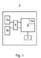
- Fig. 1 shows an example of a rotor measurement unit 1.
- Rotor measurement unit 1 is configured to be mounted onto a rotor assembly comprising a rotor shaft, the main machine rotor having a field winding, and the exciter rotor having an exciter rotor winding.
- the rotor measurement unit 1 is hence arranged to be mounted to one of the rotor shaft, the main machine rotor or to the exciter rotor.
- the rotor measurement unit 1 has attachment means for mounting it to the rotor assembly.
- the rotor measurement unit 1 comprises a measurement system 3 configured to measure a rotor parameter.
- the measurement system 3 may hence for example comprise one or more terminals, e.g. a first measurement terminal, for connection to e.g. the exciter rotor winding or the field winding.
- the measurement system 3 may also include a temperature sensor for measuring a rotor temperature.
- the rotor measurement unit 1 furthermore comprises electronic circuitry 5 configured to receive rotor parameter measurements of a rotor parameter measured by the measurement system 3.
- the electronic circuitry 5 may be configured to process the rotor parameter measurements e.g. by frequency transforming a time-domain rotor parameter measurement for example by means of a Fourier transform, and analysing the frequency spectrum by comparing it with reference frequency spectra of various faults or undesired conditions.
- the rotor measurement unit may in this case comprise a storage unit containing the reference frequency spectra, or it may receive the reference frequency spectra wirelessly from a base station in real-time or essentially in real-time during the process of comparing.
- faults or undesired conditions are inter-turn defects in the rotor winding, problems in the damper winding or stator winding, exciter winding defects, and defects in the semiconductor accessories of the multi-phase exciter rectifier of the electrical machine.
- the particular fault/undesired condition analysed depends on the rotor parameter that is being measured by the measurement system 3.
- the signature spectra of the reference frequency spectra are not the subject of the present disclosure, and will therefore not be discussed any further herein.
- the electronic circuitry 5 may in this case include processing circuitry using any combination of one or more of a suitable central processing unit (CPU), multiprocessor, microcontroller, digital signal processor (DSP), application specific integrated circuit (ASIC), field programmable gate arrays (FPGA) etc., capable of executing operations relating to fault diagnostics.
- CPU central processing unit
- DSP digital signal processor
- ASIC application specific integrated circuit
- FPGA field programmable gate arrays
- the electronic circuitry 5 may comprise a transmitter 5a.
- the transmitter 5a is configured to send data relating to the rotor parameter measurements wirelessly to a base station arranged distanced from the rotor on which the rotor measurement unit 1 is installed.
- This data relating to the rotor parameter measurements may for example be include the rotor parameter measurements as such and/or diagnosis results in variations in which the electronic circuitry 5 is able determine faults as disclosed in the previous paragraph.
- the rotor measurement unit 1 is configured to withstand the harsh conditions present in an electrical machine.
- the rotor measurement unit 1 may for example comprise a shielding structure for shielding electromagnetic forces present in an electrical machine during operation, from the electronic circuitry 5.
- the rotor measurement unit 1 comprises a first power supply terminal 7a and a second power supply terminal 7b for powering the electronic circuitry 5 both during rotating operation of the electrical machine and under a standstill condition during which the rotor is at a standstill.
- the first power supply terminal 7a is configured to be connected to a first electrical phase of a multi-phase exciter rotor winding.
- the second power supply terminal is configured to be connected to a second electrical phase of the multi-phase exciter rotor winding.
- the exciter rotor winding is furthermore connected in one of a delta connection and a wye connection.
- the rotor measurement unit 1 may thereby be powered through induction both when the rotor is rotating and when the rotor or electrical machine is in a standstill as long as the exciter stator is fed with AC power from a power converter.
- the first power supply terminal 7a is configured to be connected to a first pole of the field winding.
- the second power supply terminal is configured to be connected to a second pole of the field winding.
- the rotor measurement unit 1 may furthermore comprise a rectifier 9 configured to rectify the alternating current provided by the first power supply terminal 7a and the second power supply terminal 7b in variations in which the rotor measurement unit 1 is designed to be connected to the exciter rotor winding, to feed the electronic circuitry 5 with DC power.
- a rectifier 9 configured to rectify the alternating current provided by the first power supply terminal 7a and the second power supply terminal 7b in variations in which the rotor measurement unit 1 is designed to be connected to the exciter rotor winding, to feed the electronic circuitry 5 with DC power.
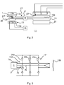
- Fig. 2 shows an example of an electrical machine 11 comprising an AC/AC exciter 13 and a power converter 15, in particular a frequency converter.
- the AC/AC exciter 13 has an exciter stator 13a and an exciter stator winding 13b provided in the exciter stator 13a.
- the power converter 15 is arranged to feed the exciter stator winding 13b with AC power. As is well-known, power converter 15 can be controlled to provide power with different frequencies and magnitude.
- the AC/AC exciter 13 furthermore has an exciter rotor 13c which forms part of the rotor assembly 12 of the electrical machine 11, and an exciter rotor winding 13d provided on the exciter rotor 13c, and which according to the example in Fig. 2 is a multi-phase winding connected in a wye connection.
- the exciter rotor winding could alternatively be connected in delta, as shown in Fig. 3 .
- the electrical machine 11 furthermore includes a multi-phase exciter rectifier 17, a main machine rotor 19, a field winding 19a provided on the main machine rotor 19, a stator 21, and a stator winding 23 arranged in the stator 21.
- the exciter rotor winding 13d is connected to the multi-phase exciter rectifier 17 which is configured to deliver DC power to the field winding 19a.
- the exciter rotor winding 13d is configured to electromagnetically interact with the exciter stator winding 13b.
- the field winding 19a and the exciter rotor winding 13d are connected via the multi-phase exciter rectifier 17.
- the multi-phase exciter rectifier 17 comprises semiconducting devices such as diodes, thyristors, IGBTs or the like for converting multi-phase AC voltage to DC voltage.
- the multi-phase exciter rectifier 17 may be a full-wave rectifier or a half-wave rectifier.
- the field winding 19a is arranged to electromagnetically interact with the stator 21 and the stator winding 23.
- the rotor measurement unit 1 is mounted on the rotor assembly 12, in particular to the exciter rotor 13c. Moreover, a base station 20 is also shown, which together with the rotor measurement unit 1 forms a monitoring system of the electrical machine 11.
- the rotor measurement unit 1 and the base station 20 are configured to wirelessly communicate.
- the rotor measurement unit 1 is arranged to transmit data relating to rotor parameter measurements, and the base station 20 is arranged to process this data.
- the base station 20 may for example be arranged to perform diagnostics of the data relating to rotor parameter measurements, e.g. by frequency transforming the data in case the data comprises a rotor parameter measurement, and comparing the thus obtained frequency spectrum with reference frequency spectra of various faults.
- Fig. 3 an example of a connection of the rotor measurement unit 1 with the exciter rotor winding 13d is shown.
- the multi-phase exciter rectifier 17 is implemented by means of diodes, but as previously mentioned, other implementations are also possible.
- the exciter rotor winding 13d has three electrical phases 25a-25c. These electrical phases 25a-25c are connected to corresponding phase legs of the AC side of the multi-phase exciter rectifier 17.
- the electrical phases 25a-25c and the phase legs will be referred to interchangeably herein.
- the exciter rotor winding 13d is connected in a delta configuration, which thereby can be seen as forming a secondary winding of a transformer, where the primary winding is the exciter stator winding 13b.
- the primary winding is the exciter stator winding 13b.
- the measurement system 3 has a first measurement terminal connected to phase leg 25a, for measuring an exciter rotor winding current. It should however be noted, as has been indicated above, that it is envisaged that other rotor parameters could be measured instead of, or in addition to the exciter rotor winding current/voltage.
- first power supply terminal 7a could instead be connected to a first pole of the field winding and the second power supply terminal 7b could instead be connected to a second pole of the field winding.
- Fig. 4 shows a similar configuration as Fig. 3 , except that the electrical phases 25a-25c of the exciter rotor winding 13d are connected in a wye configuration.
Landscapes
- Physics & Mathematics (AREA)
- General Physics & Mathematics (AREA)
- Synchronous Machinery (AREA)
Abstract
Description
- The present disclosure generally relates to electrical machines. In particular, it relates to fault condition diagnostics of an electrical machine.
- Often found in critical, high power applications, synchronous machines (SM) require reliable condition monitoring systems. Synchronous motors represent large investments and typically drive processes where downtime results in significant capital losses. Thus, detecting faults at an early stage can help to avoid catastrophic failures and is beneficial in the scheduling of maintenance actions. For a long time condition monitoring systems based on monitoring temperature, stator current and vibration have been used. However, practice has shown that detecting failures in synchronous machines is not an easy task and signatures of the failure conditions are difficult to detect by monitoring the above mentioned parameters. It has moreover been problematic to install measurement equipment on the rotor due to complications of how to power the measurement equipment.
- Accumetrics Inc. has developed an induction powered telemetry system for detecting rotor earth/ground faults and rotor temperature monitoring. This system, which is based on digital telemetry, is mounted onto the rotor. An induction loop is utilised to power the rotor measurement unit. The main drawback of this technology is the installation procedure which involves placing a power loop around the shaft.
- In addition to the complicated installation procedure Accumetrics Inc. provides a solution for rotor measurements, some of the most important failures to be detected such as inter-turn short circuits in the stator or field winding are not detectable with the existing techniques at the very early stage.
- An object of the present disclosure is to provide a rotor measurement unit for an electrical machine having an AC/AC exciter and an electrical machine comprising an AC/AC exciter which solve or at least mitigate the problems with the prior art.
- The present inventors have realised a much simpler manner of powering measurement equipment installed on a rotor of an electrical machine having an AC/AC exciter, based on the inherent induction present in such electrical machines due to the electromagnetic interaction between the exciter stator winding and the exciter rotor winding which act as primary and secondary windings of a transformer.
- Hereto, according to a first aspect of the present disclosure there is provided a rotor measurement unit configured to be mounted onto a rotor assembly of an electrical machine having an AC/AC exciter, for measuring a rotor parameter, the rotor measurement unit comprising: a measurement system configured to measure the rotor parameter, electronic circuitry configured to receive a rotor parameter measurement from the measurement system, and a first and a second power supply terminal configured to be connected to a winding of the rotor assembly to enable powering of the electronic circuitry during standstill operation of the electrical machine.
- An electrical machine having an AC/AC exciter is controlled by means of power converters. In particular, the exciter stator is fed with AC power with a controllable frequency. The phases of the exciter rotor winding are connected by means of a transformer configuration. Due to electromagnetic interaction with the exciter stator winding, current is induced in the exciter rotor winding which acts as the secondary winding of a transformer. It has been realised by the inventors that since the stator current fed by the power converter is alternating, current is induced in the exciter rotor winding also when the rotor is set in standstill operation, e.g. when rotation of the rotor is locked or when no power is provided to the main machine. This allows powering of the rotor measurement unit also during standstill operation as long as a power converter feeds the exciter stator winding with AC power. It is thereby possible to measure certain rotor parameters such as rotor temperature before for example restarting the electrical machine.
- According to one embodiment the winding is an exciter rotor winding or a field winding.
- By connecting the first and the second power supply terminal to the AC side of the multi-phase exciter rectifier, i.e. the exciter rotor winding, a higher supply voltage to the rotor measurement unit may be obtained than if the power supply terminals are connected to the DC side of the multi-phase exciter rectifier, because the line-to-line voltage on the AC side is greater than the pole-to-ground voltage on the DC side of the multi-phase exciter rectifier. Hereby, a sufficiently large voltage may be provided to the rotor measurement unit for powering it.
- According to one embodiment the rotor parameter is an electrical exciter parameter.
- According to one embodiment the measurement system comprises a first measurement terminal configured to be connected to an AC side of the multi-phase exciter rectifier.
- According to one embodiment the measurement system comprises a temperature sensor configured to measure a rotor temperature.
- According to one embodiment the electronic circuitry comprises a transmitter configured to wirelessly transmit data relating to the rotor parameter measurement to a base station.
- According to one embodiment the electronic circuitry is configured to frequency transform the rotor parameter measurement to obtain a frequency spectrum of the rotor parameter measurement.
- According to one embodiment the electronic circuitry is configured to compare the frequency spectrum with reference frequency spectra of the rotor parameter to determine whether a fault condition is present.
- According to one embodiment the transmitter is configured to wirelessly transmit data concerning a presence of a fault condition.
- One embodiment comprises a rectifier configured to rectify current obtained from the first and the second power supply terminals for powering the electronic circuitry with DC current.
- According to a second aspect of the present disclosure there is provided a monitoring system for an electrical machine comprising the rotor measurement unit according to the first aspect presented herein, and a base station, wherein the rotor measurement unit is configured to wirelessly transmit data relating to the rotor parameter measurement to the base station, and wherein the base station is configured to process the data relating to the rotor parameter measurement.
- According to a third aspect of the present disclosure there is provided an electrical machine comprising: an exciter stator, a stator, a rotor assembly comprising a main machine rotor having a field winding, and an exciter rotor having an exciter rotor winding, the exciter stator and the exciter rotor forming part of an AC/AC exciter, a multi-phase exciter rectifier arranged on the rotor assembly, and configured to rectify an AC current from the exciter rotor winding to feed the field winding with a DC current, wherein the multi-phase exciter rectifier has a plurality of phase legs, each phase leg being connected to a respective electrical phase of the exciter rotor winding, and a rotor measurement unit according to the first aspect of the present disclosure or a monitoring system according to the second aspect.
- According to one embodiment the rotor measurement unit is mounted onto the rotor assembly and wherein the first and the second power supply terminals are connected to respective electrical phases of the exciter rotor winding or to a respective pole on a DC side of the multi-phase exciter rectifier.
- According to one embodiment the exciter rotor winding is connected in a delta connection or a wye connection.
- One embodiment comprises a power converter configured to feed the exciter stator with an AC current.
- Generally, all terms used in the claims are to be interpreted according to their ordinary meaning in the technical field, unless explicitly defined otherwise herein. All references to "a/an/the element, apparatus, component, means, etc. are to be interpreted openly as referring to at least one instance of the element, apparatus, component, means, etc., unless explicitly stated otherwise.
- The specific embodiments of the inventive concept will now be described, by way of example, with reference to the accompanying drawings, in which:
-
Fig. 1 schematically shows an example of a rotor measurement unit; -
Fig. 2 schematically shows an example of an electrical machine having an AC/AC exciter; -
Fig. 3 schematically shows an example of a rotor measurement unit connected to an exciter rotor winding that is delta connected; and -
Fig. 4 schematically shows an example of a rotor measurement unit connected to an exciter rotor winding that is wye connected. - The inventive concept will now be described more fully hereinafter with reference to the accompanying drawings, in which exemplifying embodiments are shown. The inventive concept may, however, be embodied in many different forms and should not be construed as limited to the embodiments set forth herein; rather, these embodiments are provided by way of example so that this disclosure will be thorough and complete, and will fully convey the scope of the inventive concept to those skilled in the art. Like numbers refer to like elements throughout the description.
- The present disclosure relates to a rotor measurement unit configured to measure one or more rotor parameters of a rotating electrical machine having an AC/AC exciter. The rotating electrical machine may in particular be a synchronous machine such as a synchronous motor or a synchronous generator. The rotor parameters are advantageously related to the AC/AC exciter, e.g. electrical exciter parameters and/or thermal exciter rotor parameters, or to a main machine rotor. The rotor measurement unit is arranged to be assembled to or installed onto the rotor assembly, which includes the exciter rotor, the main machine rotor and the rotor shaft.
- The rotor measurement unit may be specifically configured to be connected to the exciter rotor winding which is connected in a delta or wye configuration, or equivalently, to the AC side of a multi-phase exciter rectifier which is configured to rectify AC current induced in the exciter rotor winding to DC current to feed the field winding for powering the rotor measurement unit. Alternatively, the rotor measurement unit may be configured to be connected to the field winding, i.e. to the DC side of the multi-phase exciter rectifier. In this latter case, the rotor measurement unit may be configured to be connected to the two electrical poles of the field winding.
- Hence, the rotor measurement unit has a first and a second power supply terminal connectable to a first electrical phase and a second electrical phase, respectively, of the exciter rotor winding, or to the plus pole and the minus pole of the field winding. Hereby, the rotor measurement unit is able to be powered both during rotation of the rotor and when the rotor is at standstill, as long as the power converter feeds the exciter stator with AC power while the rotor is at a standstill.
- The rotor measurement unit is furthermore configured to measure at least one rotor parameter of the rotor by means of a measurement system. Such rotor parameters may for example be an electrical rotor parameter, for example a field winding current, a field winding voltage, or an electrical exciter parameter such as an exciter rotor winding voltage, an exciter rotor winding current, or a rotor temperature. The measurement system is configured to provide any rotor parameter measurement to electronic circuitry of the rotor measurement unit for handling the rotor parameter measurement.
-
Fig. 1 shows an example of arotor measurement unit 1.Rotor measurement unit 1 is configured to be mounted onto a rotor assembly comprising a rotor shaft, the main machine rotor having a field winding, and the exciter rotor having an exciter rotor winding. Therotor measurement unit 1 is hence arranged to be mounted to one of the rotor shaft, the main machine rotor or to the exciter rotor. To this end, therotor measurement unit 1 has attachment means for mounting it to the rotor assembly. - The
rotor measurement unit 1 comprises ameasurement system 3 configured to measure a rotor parameter. Themeasurement system 3 may hence for example comprise one or more terminals, e.g. a first measurement terminal, for connection to e.g. the exciter rotor winding or the field winding. Themeasurement system 3 may also include a temperature sensor for measuring a rotor temperature. - The
rotor measurement unit 1 furthermore comprises electronic circuitry 5 configured to receive rotor parameter measurements of a rotor parameter measured by themeasurement system 3. - According to one variation, the electronic circuitry 5 may be configured to process the rotor parameter measurements e.g. by frequency transforming a time-domain rotor parameter measurement for example by means of a Fourier transform, and analysing the frequency spectrum by comparing it with reference frequency spectra of various faults or undesired conditions.
- The rotor measurement unit may in this case comprise a storage unit containing the reference frequency spectra, or it may receive the reference frequency spectra wirelessly from a base station in real-time or essentially in real-time during the process of comparing. Examples of such faults or undesired conditions are inter-turn defects in the rotor winding, problems in the damper winding or stator winding, exciter winding defects, and defects in the semiconductor accessories of the multi-phase exciter rectifier of the electrical machine. The particular fault/undesired condition analysed depends on the rotor parameter that is being measured by the
measurement system 3. The signature spectra of the reference frequency spectra are not the subject of the present disclosure, and will therefore not be discussed any further herein. The electronic circuitry 5 may in this case include processing circuitry using any combination of one or more of a suitable central processing unit (CPU), multiprocessor, microcontroller, digital signal processor (DSP), application specific integrated circuit (ASIC), field programmable gate arrays (FPGA) etc., capable of executing operations relating to fault diagnostics. - According to one variation, the electronic circuitry 5 may comprise a
transmitter 5a. Thetransmitter 5a is configured to send data relating to the rotor parameter measurements wirelessly to a base station arranged distanced from the rotor on which therotor measurement unit 1 is installed. This data relating to the rotor parameter measurements may for example be include the rotor parameter measurements as such and/or diagnosis results in variations in which the electronic circuitry 5 is able determine faults as disclosed in the previous paragraph. - The
rotor measurement unit 1 is configured to withstand the harsh conditions present in an electrical machine. Therotor measurement unit 1 may for example comprise a shielding structure for shielding electromagnetic forces present in an electrical machine during operation, from the electronic circuitry 5. - The
rotor measurement unit 1 comprises a firstpower supply terminal 7a and a secondpower supply terminal 7b for powering the electronic circuitry 5 both during rotating operation of the electrical machine and under a standstill condition during which the rotor is at a standstill. - According to one variation the first
power supply terminal 7a is configured to be connected to a first electrical phase of a multi-phase exciter rotor winding. The second power supply terminal is configured to be connected to a second electrical phase of the multi-phase exciter rotor winding. The exciter rotor winding is furthermore connected in one of a delta connection and a wye connection. Therotor measurement unit 1 may thereby be powered through induction both when the rotor is rotating and when the rotor or electrical machine is in a standstill as long as the exciter stator is fed with AC power from a power converter. - According to another variation, the first
power supply terminal 7a is configured to be connected to a first pole of the field winding. The second power supply terminal is configured to be connected to a second pole of the field winding. - The
rotor measurement unit 1 may furthermore comprise arectifier 9 configured to rectify the alternating current provided by the firstpower supply terminal 7a and the secondpower supply terminal 7b in variations in which therotor measurement unit 1 is designed to be connected to the exciter rotor winding, to feed the electronic circuitry 5 with DC power. -
Fig. 2 shows an example of anelectrical machine 11 comprising an AC/AC exciter 13 and apower converter 15, in particular a frequency converter. The AC/AC exciter 13 has anexciter stator 13a and an exciter stator winding 13b provided in theexciter stator 13a. Thepower converter 15 is arranged to feed the exciter stator winding 13b with AC power. As is well-known,power converter 15 can be controlled to provide power with different frequencies and magnitude. The AC/AC exciter 13 furthermore has anexciter rotor 13c which forms part of therotor assembly 12 of theelectrical machine 11, and an exciter rotor winding 13d provided on theexciter rotor 13c, and which according to the example inFig. 2 is a multi-phase winding connected in a wye connection. The exciter rotor winding could alternatively be connected in delta, as shown inFig. 3 . - The
electrical machine 11 furthermore includes amulti-phase exciter rectifier 17, amain machine rotor 19, a field winding 19a provided on themain machine rotor 19, astator 21, and a stator winding 23 arranged in thestator 21. - The exciter rotor winding 13d is connected to the
multi-phase exciter rectifier 17 which is configured to deliver DC power to the field winding 19a. The exciter rotor winding 13d is configured to electromagnetically interact with the exciter stator winding 13b. - The field winding 19a and the exciter rotor winding 13d are connected via the
multi-phase exciter rectifier 17. Themulti-phase exciter rectifier 17 comprises semiconducting devices such as diodes, thyristors, IGBTs or the like for converting multi-phase AC voltage to DC voltage. Themulti-phase exciter rectifier 17 may be a full-wave rectifier or a half-wave rectifier. - The field winding 19a is arranged to electromagnetically interact with the
stator 21 and the stator winding 23. - According to the example in
Fig. 2 , therotor measurement unit 1 is mounted on therotor assembly 12, in particular to theexciter rotor 13c. Moreover, abase station 20 is also shown, which together with therotor measurement unit 1 forms a monitoring system of theelectrical machine 11. Therotor measurement unit 1 and thebase station 20 are configured to wirelessly communicate. In particular, therotor measurement unit 1 is arranged to transmit data relating to rotor parameter measurements, and thebase station 20 is arranged to process this data. Thebase station 20 may for example be arranged to perform diagnostics of the data relating to rotor parameter measurements, e.g. by frequency transforming the data in case the data comprises a rotor parameter measurement, and comparing the thus obtained frequency spectrum with reference frequency spectra of various faults. - Turning now to
Fig. 3 , an example of a connection of therotor measurement unit 1 with the exciter rotor winding 13d is shown. In this example, themulti-phase exciter rectifier 17 is implemented by means of diodes, but as previously mentioned, other implementations are also possible. - In the case of the example in
Fig. 3 , the exciter rotor winding 13d has threeelectrical phases 25a-25c. Theseelectrical phases 25a-25c are connected to corresponding phase legs of the AC side of themulti-phase exciter rectifier 17. Hereto, theelectrical phases 25a-25c and the phase legs will be referred to interchangeably herein. - According to the present example, the exciter rotor winding 13d is connected in a delta configuration, which thereby can be seen as forming a secondary winding of a transformer, where the primary winding is the exciter stator winding 13b. Thus, when the
rotor assembly 12 is in a standstill, and if the exciter stator winding 13b is fed with an AC current from thepower converter 15, currents will be induced in the electrical phases orphase legs 25a-25c. The firstpower supply terminal 7a is connected to electrical phase orphase leg 25a and the secondpower supply terminal 7b is connected to electrical phase orphase leg 25b. - Moreover, according to the example, the
measurement system 3 has a first measurement terminal connected to phaseleg 25a, for measuring an exciter rotor winding current. It should however be noted, as has been indicated above, that it is envisaged that other rotor parameters could be measured instead of, or in addition to the exciter rotor winding current/voltage. - It should be noted in a variation of this example that the first
power supply terminal 7a could instead be connected to a first pole of the field winding and the secondpower supply terminal 7b could instead be connected to a second pole of the field winding. -
Fig. 4 shows a similar configuration asFig. 3 , except that theelectrical phases 25a-25c of the exciter rotor winding 13d are connected in a wye configuration. - The inventive concept has mainly been described above with reference to a few examples. However, as is readily appreciated by a person skilled in the art, other embodiments than the ones disclosed above are equally possible within the scope of the inventive concept, as defined by the appended claims.
Claims (15)
- A rotor measurement unit (1) configured to be mounted onto a rotor assembly (12) of an electrical machine (11) having an AC/AC exciter (13), for measuring a rotor parameter, the rotor measurement unit (1) comprising:a measurement system (3) configured to measure the rotor parameter,electronic circuitry (5) configured to receive a rotor parameter measurement from the measurement system (3), anda first and a second power supply terminal (7a, 7b) configured to be connected to a winding of the rotor assembly (12) to enable powering of the electronic circuitry (5) during standstill operation of the electrical machine (11).
- The rotor measurement unit (1) as claimed in claim 1, wherein the winding is an exciter rotor winding (13d) or a field winding (19a).
- The rotor measurement unit (1) as claimed in claim 1 or 2, wherein the rotor parameter is an electrical exciter parameter.
- The rotor measurement unit (1) as claimed in any of the preceding claims, wherein the measurement system (3) comprises a first measurement terminal configured to be connected to an AC side of a multi-phase exciter rectifier (17) of the electrical machine (11).
- The rotor measurement unit (1) as claimed in any of the preceding claims, wherein the measurement system (3) comprises a temperature sensor configured to measure a rotor temperature.
- The rotor measurement unit (1) as claimed in any of the preceding claims, wherein the electronic circuitry (5) comprises a transmitter (5a) configured to wirelessly transmit data relating to the rotor parameter measurement to a base station (20).
- The rotor measurement unit (1) as claimed in any of the preceding claims, wherein the electronic circuitry (5) is configured to frequency transform the rotor parameter measurement to obtain a frequency spectrum of the rotor parameter measurement.
- The rotor measurement unit (1) as claimed in claim 7, wherein the electronic circuitry (5) is configured to compare the frequency spectrum with reference frequency spectra of the rotor parameter to determine whether a fault condition is present.
- The rotor measurement unit (1) as claimed in claim 8, wherein the transmitter is configured to wirelessly transmit data concerning a presence of a fault condition.
- The rotor measurement unit (1) as claimed in any of the preceding claims, comprising a rectifier (9) configured to rectify current obtained from the first and the second power supply terminals (7a, 7b) for powering the electronic circuitry (5) with DC current.
- A monitoring system (1, 20) for an electrical machine (11) comprising the rotor measurement unit (1) as claimed in any of claims 1-10 and a base station (20), wherein the rotor measurement unit (1) is configured to wirelessly transmit data relating to the rotor parameter measurement to the base station (20), and wherein the base station (20) is configured to process the data relating to the rotor parameter measurement.
- An electrical machine (11) comprising:an exciter stator (13a),a stator (21),a rotor assembly (12) comprising a main machine rotor (19) having a field winding (19a), and an exciter rotor (13c) having an exciter rotor winding (13d), the exciter stator (13a) and the exciter rotor (13c) forming part of an AC/AC exciter (13),a multi-phase exciter rectifier (17) arranged on the rotor assembly (12), and configured to rectify an AC current from the exciter rotor winding (13d) to feed the field winding (19a) with a DC current, wherein the multi-phase exciter rectifier (17) has a plurality of phase legs (25a-25c), each phase leg (25a-25c) being connected to a respective electrical phase of the exciter rotor winding, anda rotor measurement unit (11) as claimed in any of claims 1-10 or a monitoring system (1, 20) as claimed claim 11.
- The electrical machine (11) as claimed in claim 12, wherein the rotor measurement unit (1) is mounted onto the rotor assembly (12) and wherein the first and the second power supply terminals (7a, 7b) are connected to respective electrical phases (25a, 25b) of the exciter rotor winding (13d).
- The electrical machine (11) as claimed in claim 12 or 13, wherein the exciter field winding is connected in a delta connection or a wye connection.
- The electrical machine (11) as claimed in any of claims 12-14, comprising a power converter (15) configured to feed the exciter stator (13a) with an AC current.
Priority Applications (1)
| Application Number | Priority Date | Filing Date | Title |
|---|---|---|---|
| EP16165707.7A EP3236275B1 (en) | 2016-04-18 | 2016-04-18 | Electrical machine comprising a rotor measurement unit for measuring a rotor parameter of the electrical machine |
Applications Claiming Priority (1)
| Application Number | Priority Date | Filing Date | Title |
|---|---|---|---|
| EP16165707.7A EP3236275B1 (en) | 2016-04-18 | 2016-04-18 | Electrical machine comprising a rotor measurement unit for measuring a rotor parameter of the electrical machine |
Publications (2)
| Publication Number | Publication Date |
|---|---|
| EP3236275A1 true EP3236275A1 (en) | 2017-10-25 |
| EP3236275B1 EP3236275B1 (en) | 2021-11-17 |
Family
ID=55759518
Family Applications (1)
| Application Number | Title | Priority Date | Filing Date |
|---|---|---|---|
| EP16165707.7A Active EP3236275B1 (en) | 2016-04-18 | 2016-04-18 | Electrical machine comprising a rotor measurement unit for measuring a rotor parameter of the electrical machine |
Country Status (1)
| Country | Link |
|---|---|
| EP (1) | EP3236275B1 (en) |
Cited By (2)
| Publication number | Priority date | Publication date | Assignee | Title |
|---|---|---|---|---|
| WO2018184673A1 (en) * | 2017-04-05 | 2018-10-11 | Abb Schweiz Ag | An electrical machine comprising a rotor measurement unit for measuring a rotor parameter of the electrical machine |
| US12399068B2 (en) | 2020-12-02 | 2025-08-26 | Pro-Micron Gmbh | Status monitoring for a rotating element of a motor or work machine, more particularly for the rotor of an electric motor |
Citations (6)
| Publication number | Priority date | Publication date | Assignee | Title |
|---|---|---|---|---|
| US6693778B1 (en) * | 1999-12-07 | 2004-02-17 | Sensotec, Inc. | Diode fault detection and ground fault detection systems |
| DE102009025858A1 (en) * | 2008-05-30 | 2009-12-03 | General Electric Co. | A method and apparatus for detecting a fault in a brushless exciter stage for a generator |
| WO2011109489A1 (en) * | 2010-03-02 | 2011-09-09 | Accumetrics Associates, Inc. | Method and apparatus for fault detection of series diodes in rectifiers |
| EP2743669A1 (en) * | 2012-12-17 | 2014-06-18 | General Electric Company | Fault detection system and associated method |
| EP2905630A2 (en) * | 2014-01-16 | 2015-08-12 | Rolls-Royce plc | Fault detection in brushless exciters |
| EP2995967A1 (en) * | 2014-09-10 | 2016-03-16 | ABB Technology Ltd | Method and system for determining a synchronous machine fault condition |
-
2016
- 2016-04-18 EP EP16165707.7A patent/EP3236275B1/en active Active
Patent Citations (6)
| Publication number | Priority date | Publication date | Assignee | Title |
|---|---|---|---|---|
| US6693778B1 (en) * | 1999-12-07 | 2004-02-17 | Sensotec, Inc. | Diode fault detection and ground fault detection systems |
| DE102009025858A1 (en) * | 2008-05-30 | 2009-12-03 | General Electric Co. | A method and apparatus for detecting a fault in a brushless exciter stage for a generator |
| WO2011109489A1 (en) * | 2010-03-02 | 2011-09-09 | Accumetrics Associates, Inc. | Method and apparatus for fault detection of series diodes in rectifiers |
| EP2743669A1 (en) * | 2012-12-17 | 2014-06-18 | General Electric Company | Fault detection system and associated method |
| EP2905630A2 (en) * | 2014-01-16 | 2015-08-12 | Rolls-Royce plc | Fault detection in brushless exciters |
| EP2995967A1 (en) * | 2014-09-10 | 2016-03-16 | ABB Technology Ltd | Method and system for determining a synchronous machine fault condition |
Cited By (2)
| Publication number | Priority date | Publication date | Assignee | Title |
|---|---|---|---|---|
| WO2018184673A1 (en) * | 2017-04-05 | 2018-10-11 | Abb Schweiz Ag | An electrical machine comprising a rotor measurement unit for measuring a rotor parameter of the electrical machine |
| US12399068B2 (en) | 2020-12-02 | 2025-08-26 | Pro-Micron Gmbh | Status monitoring for a rotating element of a motor or work machine, more particularly for the rotor of an electric motor |
Also Published As
| Publication number | Publication date |
|---|---|
| EP3236275B1 (en) | 2021-11-17 |
Similar Documents
| Publication | Publication Date | Title |
|---|---|---|
| EP3321706B1 (en) | Method and system for determining a synchronous machine fault condition | |
| US8924170B2 (en) | Method and system for detecting a failed rectifier in an AC/DC converter | |
| EP2908148B1 (en) | Rectifier diode fault detection in brushless exciters | |
| Puche-Panadero et al. | Improved resolution of the MCSA method via Hilbert transform, enabling the diagnosis of rotor asymmetries at very low slip | |
| US20170030984A1 (en) | Method to detect or monitor the demagnetization of a magnet | |
| EP3480610B1 (en) | Diagnosing a winding set of a stator | |
| US10082531B2 (en) | Electrical machine component failure detection apparatus and method | |
| US10877098B2 (en) | Method for detecting a fault in an electrical machine | |
| US20200088795A1 (en) | Methods and systems for monitoring the performance of electric motors | |
| CN114364998A (en) | Method of detecting rotor bar failure and method of estimating additional operational expenditure due to one or more mechanical anomalies in an electric machine | |
| Ewert | Use of axial flux in the detection of electrical faults in induction motors | |
| US8362730B2 (en) | Synchronous machine starting device | |
| EP3236275B1 (en) | Electrical machine comprising a rotor measurement unit for measuring a rotor parameter of the electrical machine | |
| WO2018184673A1 (en) | An electrical machine comprising a rotor measurement unit for measuring a rotor parameter of the electrical machine | |
| RU2623696C1 (en) | Way and generator rotor current measuring device with the brushless excitation | |
| Cristaldi et al. | An inverter-fed induction motor diagnostic tool based on time-domain current analysis | |
| Biot-Monterde et al. | Assessment of the rotor condition in soft-started induction motors through the Hilbert transform of transient stray flux signals | |
| BR112019020129B1 (en) | ELECTRICAL MACHINE COMPRISING A ROTOR MEASUREMENT UNIT FOR MEASURING A ROTOR PARAMETER OF THE ELECTRICAL MACHINE | |
| EP2704310B1 (en) | Method for operating such an electrical machine | |
| EP4677375B1 (en) | Method of detecting fault in excitation rectifier of synchronous generator | |
| US20250317029A1 (en) | Systems and Methods for Using Auxiliary Windings of an Electric Motor for Powering Electronic Components | |
| JP6482028B2 (en) | Synchronous motor | |
| CN121324927A (en) | Diagnostic devices, power conversion devices and diagnostic methods | |
| CN110235011A (en) | For carrying out the method and electric generator inspection system that failure determines at generator | |
| WO2024157054A1 (en) | System and methods for detecting electrical imbalance and early-stage winding failure for industrial induction motors |
Legal Events
| Date | Code | Title | Description |
|---|---|---|---|
| PUAI | Public reference made under article 153(3) epc to a published international application that has entered the european phase |
Free format text: ORIGINAL CODE: 0009012 |
|
| STAA | Information on the status of an ep patent application or granted ep patent |
Free format text: STATUS: THE APPLICATION HAS BEEN PUBLISHED |
|
| AK | Designated contracting states |
Kind code of ref document: A1 Designated state(s): AL AT BE BG CH CY CZ DE DK EE ES FI FR GB GR HR HU IE IS IT LI LT LU LV MC MK MT NL NO PL PT RO RS SE SI SK SM TR |
|
| AX | Request for extension of the european patent |
Extension state: BA ME |
|
| STAA | Information on the status of an ep patent application or granted ep patent |
Free format text: STATUS: REQUEST FOR EXAMINATION WAS MADE |
|
| 17P | Request for examination filed |
Effective date: 20180425 |
|
| RBV | Designated contracting states (corrected) |
Designated state(s): AL AT BE BG CH CY CZ DE DK EE ES FI FR GB GR HR HU IE IS IT LI LT LU LV MC MK MT NL NO PL PT RO RS SE SI SK SM TR |
|
| GRAP | Despatch of communication of intention to grant a patent |
Free format text: ORIGINAL CODE: EPIDOSNIGR1 |
|
| STAA | Information on the status of an ep patent application or granted ep patent |
Free format text: STATUS: GRANT OF PATENT IS INTENDED |
|
| INTG | Intention to grant announced |
Effective date: 20210609 |
|
| GRAS | Grant fee paid |
Free format text: ORIGINAL CODE: EPIDOSNIGR3 |
|
| GRAA | (expected) grant |
Free format text: ORIGINAL CODE: 0009210 |
|
| STAA | Information on the status of an ep patent application or granted ep patent |
Free format text: STATUS: THE PATENT HAS BEEN GRANTED |
|
| AK | Designated contracting states |
Kind code of ref document: B1 Designated state(s): AL AT BE BG CH CY CZ DE DK EE ES FI FR GB GR HR HU IE IS IT LI LT LU LV MC MK MT NL NO PL PT RO RS SE SI SK SM TR |
|
| RAP3 | Party data changed (applicant data changed or rights of an application transferred) |
Owner name: ABB SCHWEIZ AG |
|
| REG | Reference to a national code |
Ref country code: GB Ref legal event code: FG4D |
|
| REG | Reference to a national code |
Ref country code: DE Ref legal event code: R096 Ref document number: 602016066239 Country of ref document: DE |
|
| REG | Reference to a national code |
Ref country code: IE Ref legal event code: FG4D |
|
| REG | Reference to a national code |
Ref country code: AT Ref legal event code: REF Ref document number: 1448473 Country of ref document: AT Kind code of ref document: T Effective date: 20211215 |
|
| REG | Reference to a national code |
Ref country code: SE Ref legal event code: TRGR |
|
| REG | Reference to a national code |
Ref country code: LT Ref legal event code: MG9D |
|
| REG | Reference to a national code |
Ref country code: NL Ref legal event code: MP Effective date: 20211117 |
|
| REG | Reference to a national code |
Ref country code: AT Ref legal event code: MK05 Ref document number: 1448473 Country of ref document: AT Kind code of ref document: T Effective date: 20211117 |
|
| PG25 | Lapsed in a contracting state [announced via postgrant information from national office to epo] |
Ref country code: RS Free format text: LAPSE BECAUSE OF FAILURE TO SUBMIT A TRANSLATION OF THE DESCRIPTION OR TO PAY THE FEE WITHIN THE PRESCRIBED TIME-LIMIT Effective date: 20211117 Ref country code: LT Free format text: LAPSE BECAUSE OF FAILURE TO SUBMIT A TRANSLATION OF THE DESCRIPTION OR TO PAY THE FEE WITHIN THE PRESCRIBED TIME-LIMIT Effective date: 20211117 Ref country code: FI Free format text: LAPSE BECAUSE OF FAILURE TO SUBMIT A TRANSLATION OF THE DESCRIPTION OR TO PAY THE FEE WITHIN THE PRESCRIBED TIME-LIMIT Effective date: 20211117 Ref country code: BG Free format text: LAPSE BECAUSE OF FAILURE TO SUBMIT A TRANSLATION OF THE DESCRIPTION OR TO PAY THE FEE WITHIN THE PRESCRIBED TIME-LIMIT Effective date: 20220217 Ref country code: AT Free format text: LAPSE BECAUSE OF FAILURE TO SUBMIT A TRANSLATION OF THE DESCRIPTION OR TO PAY THE FEE WITHIN THE PRESCRIBED TIME-LIMIT Effective date: 20211117 |
|
| PG25 | Lapsed in a contracting state [announced via postgrant information from national office to epo] |
Ref country code: IS Free format text: LAPSE BECAUSE OF FAILURE TO SUBMIT A TRANSLATION OF THE DESCRIPTION OR TO PAY THE FEE WITHIN THE PRESCRIBED TIME-LIMIT Effective date: 20220317 Ref country code: PT Free format text: LAPSE BECAUSE OF FAILURE TO SUBMIT A TRANSLATION OF THE DESCRIPTION OR TO PAY THE FEE WITHIN THE PRESCRIBED TIME-LIMIT Effective date: 20220317 Ref country code: PL Free format text: LAPSE BECAUSE OF FAILURE TO SUBMIT A TRANSLATION OF THE DESCRIPTION OR TO PAY THE FEE WITHIN THE PRESCRIBED TIME-LIMIT Effective date: 20211117 Ref country code: NO Free format text: LAPSE BECAUSE OF FAILURE TO SUBMIT A TRANSLATION OF THE DESCRIPTION OR TO PAY THE FEE WITHIN THE PRESCRIBED TIME-LIMIT Effective date: 20220217 Ref country code: NL Free format text: LAPSE BECAUSE OF FAILURE TO SUBMIT A TRANSLATION OF THE DESCRIPTION OR TO PAY THE FEE WITHIN THE PRESCRIBED TIME-LIMIT Effective date: 20211117 Ref country code: LV Free format text: LAPSE BECAUSE OF FAILURE TO SUBMIT A TRANSLATION OF THE DESCRIPTION OR TO PAY THE FEE WITHIN THE PRESCRIBED TIME-LIMIT Effective date: 20211117 Ref country code: HR Free format text: LAPSE BECAUSE OF FAILURE TO SUBMIT A TRANSLATION OF THE DESCRIPTION OR TO PAY THE FEE WITHIN THE PRESCRIBED TIME-LIMIT Effective date: 20211117 Ref country code: GR Free format text: LAPSE BECAUSE OF FAILURE TO SUBMIT A TRANSLATION OF THE DESCRIPTION OR TO PAY THE FEE WITHIN THE PRESCRIBED TIME-LIMIT Effective date: 20220218 Ref country code: ES Free format text: LAPSE BECAUSE OF FAILURE TO SUBMIT A TRANSLATION OF THE DESCRIPTION OR TO PAY THE FEE WITHIN THE PRESCRIBED TIME-LIMIT Effective date: 20211117 |
|
| PG25 | Lapsed in a contracting state [announced via postgrant information from national office to epo] |
Ref country code: SM Free format text: LAPSE BECAUSE OF FAILURE TO SUBMIT A TRANSLATION OF THE DESCRIPTION OR TO PAY THE FEE WITHIN THE PRESCRIBED TIME-LIMIT Effective date: 20211117 Ref country code: SK Free format text: LAPSE BECAUSE OF FAILURE TO SUBMIT A TRANSLATION OF THE DESCRIPTION OR TO PAY THE FEE WITHIN THE PRESCRIBED TIME-LIMIT Effective date: 20211117 Ref country code: RO Free format text: LAPSE BECAUSE OF FAILURE TO SUBMIT A TRANSLATION OF THE DESCRIPTION OR TO PAY THE FEE WITHIN THE PRESCRIBED TIME-LIMIT Effective date: 20211117 Ref country code: EE Free format text: LAPSE BECAUSE OF FAILURE TO SUBMIT A TRANSLATION OF THE DESCRIPTION OR TO PAY THE FEE WITHIN THE PRESCRIBED TIME-LIMIT Effective date: 20211117 Ref country code: DK Free format text: LAPSE BECAUSE OF FAILURE TO SUBMIT A TRANSLATION OF THE DESCRIPTION OR TO PAY THE FEE WITHIN THE PRESCRIBED TIME-LIMIT Effective date: 20211117 Ref country code: CZ Free format text: LAPSE BECAUSE OF FAILURE TO SUBMIT A TRANSLATION OF THE DESCRIPTION OR TO PAY THE FEE WITHIN THE PRESCRIBED TIME-LIMIT Effective date: 20211117 |
|
| REG | Reference to a national code |
Ref country code: DE Ref legal event code: R097 Ref document number: 602016066239 Country of ref document: DE |
|
| PLBE | No opposition filed within time limit |
Free format text: ORIGINAL CODE: 0009261 |
|
| STAA | Information on the status of an ep patent application or granted ep patent |
Free format text: STATUS: NO OPPOSITION FILED WITHIN TIME LIMIT |
|
| 26N | No opposition filed |
Effective date: 20220818 |
|
| PG25 | Lapsed in a contracting state [announced via postgrant information from national office to epo] |
Ref country code: AL Free format text: LAPSE BECAUSE OF FAILURE TO SUBMIT A TRANSLATION OF THE DESCRIPTION OR TO PAY THE FEE WITHIN THE PRESCRIBED TIME-LIMIT Effective date: 20211117 |
|
| PG25 | Lapsed in a contracting state [announced via postgrant information from national office to epo] |
Ref country code: SI Free format text: LAPSE BECAUSE OF FAILURE TO SUBMIT A TRANSLATION OF THE DESCRIPTION OR TO PAY THE FEE WITHIN THE PRESCRIBED TIME-LIMIT Effective date: 20211117 |
|
| REG | Reference to a national code |
Ref country code: CH Ref legal event code: PL |
|
| REG | Reference to a national code |
Ref country code: BE Ref legal event code: MM Effective date: 20220430 |
|
| PG25 | Lapsed in a contracting state [announced via postgrant information from national office to epo] |
Ref country code: MC Free format text: LAPSE BECAUSE OF FAILURE TO SUBMIT A TRANSLATION OF THE DESCRIPTION OR TO PAY THE FEE WITHIN THE PRESCRIBED TIME-LIMIT Effective date: 20211117 Ref country code: LU Free format text: LAPSE BECAUSE OF NON-PAYMENT OF DUE FEES Effective date: 20220418 Ref country code: LI Free format text: LAPSE BECAUSE OF NON-PAYMENT OF DUE FEES Effective date: 20220430 Ref country code: CH Free format text: LAPSE BECAUSE OF NON-PAYMENT OF DUE FEES Effective date: 20220430 |
|
| PG25 | Lapsed in a contracting state [announced via postgrant information from national office to epo] |
Ref country code: BE Free format text: LAPSE BECAUSE OF NON-PAYMENT OF DUE FEES Effective date: 20220430 |
|
| PG25 | Lapsed in a contracting state [announced via postgrant information from national office to epo] |
Ref country code: IE Free format text: LAPSE BECAUSE OF NON-PAYMENT OF DUE FEES Effective date: 20220418 |
|
| PG25 | Lapsed in a contracting state [announced via postgrant information from national office to epo] |
Ref country code: IT Free format text: LAPSE BECAUSE OF FAILURE TO SUBMIT A TRANSLATION OF THE DESCRIPTION OR TO PAY THE FEE WITHIN THE PRESCRIBED TIME-LIMIT Effective date: 20211117 |
|
| PG25 | Lapsed in a contracting state [announced via postgrant information from national office to epo] |
Ref country code: HU Free format text: LAPSE BECAUSE OF FAILURE TO SUBMIT A TRANSLATION OF THE DESCRIPTION OR TO PAY THE FEE WITHIN THE PRESCRIBED TIME-LIMIT; INVALID AB INITIO Effective date: 20160418 |
|
| PG25 | Lapsed in a contracting state [announced via postgrant information from national office to epo] |
Ref country code: MK Free format text: LAPSE BECAUSE OF FAILURE TO SUBMIT A TRANSLATION OF THE DESCRIPTION OR TO PAY THE FEE WITHIN THE PRESCRIBED TIME-LIMIT Effective date: 20211117 Ref country code: CY Free format text: LAPSE BECAUSE OF FAILURE TO SUBMIT A TRANSLATION OF THE DESCRIPTION OR TO PAY THE FEE WITHIN THE PRESCRIBED TIME-LIMIT Effective date: 20211117 |
|
| PG25 | Lapsed in a contracting state [announced via postgrant information from national office to epo] |
Ref country code: TR Free format text: LAPSE BECAUSE OF FAILURE TO SUBMIT A TRANSLATION OF THE DESCRIPTION OR TO PAY THE FEE WITHIN THE PRESCRIBED TIME-LIMIT Effective date: 20211117 |
|
| PG25 | Lapsed in a contracting state [announced via postgrant information from national office to epo] |
Ref country code: MT Free format text: LAPSE BECAUSE OF FAILURE TO SUBMIT A TRANSLATION OF THE DESCRIPTION OR TO PAY THE FEE WITHIN THE PRESCRIBED TIME-LIMIT Effective date: 20211117 |
|
| PGFP | Annual fee paid to national office [announced via postgrant information from national office to epo] |
Ref country code: DE Payment date: 20250422 Year of fee payment: 10 |
|
| PGFP | Annual fee paid to national office [announced via postgrant information from national office to epo] |
Ref country code: GB Payment date: 20250423 Year of fee payment: 10 |
|
| PGFP | Annual fee paid to national office [announced via postgrant information from national office to epo] |
Ref country code: FR Payment date: 20250425 Year of fee payment: 10 |
|
| PGFP | Annual fee paid to national office [announced via postgrant information from national office to epo] |
Ref country code: SE Payment date: 20250429 Year of fee payment: 10 |