EP3236095B1 - Bearing - Google Patents
Bearing Download PDFInfo
- Publication number
- EP3236095B1 EP3236095B1 EP17165706.7A EP17165706A EP3236095B1 EP 3236095 B1 EP3236095 B1 EP 3236095B1 EP 17165706 A EP17165706 A EP 17165706A EP 3236095 B1 EP3236095 B1 EP 3236095B1
- Authority
- EP
- European Patent Office
- Prior art keywords
- bearing
- fluid damper
- damper cavity
- pad
- wall
- Prior art date
- Legal status (The legal status is an assumption and is not a legal conclusion. Google has not performed a legal analysis and makes no representation as to the accuracy of the status listed.)
- Active
Links
Images


Classifications
-
- F—MECHANICAL ENGINEERING; LIGHTING; HEATING; WEAPONS; BLASTING
- F01—MACHINES OR ENGINES IN GENERAL; ENGINE PLANTS IN GENERAL; STEAM ENGINES
- F01D—NON-POSITIVE DISPLACEMENT MACHINES OR ENGINES, e.g. STEAM TURBINES
- F01D25/00—Component parts, details, or accessories, not provided for in, or of interest apart from, other groups
- F01D25/16—Arrangement of bearings; Supporting or mounting bearings in casings
- F01D25/162—Bearing supports
- F01D25/164—Flexible supports; Vibration damping means associated with the bearing
-
- F—MECHANICAL ENGINEERING; LIGHTING; HEATING; WEAPONS; BLASTING
- F16—ENGINEERING ELEMENTS AND UNITS; GENERAL MEASURES FOR PRODUCING AND MAINTAINING EFFECTIVE FUNCTIONING OF MACHINES OR INSTALLATIONS; THERMAL INSULATION IN GENERAL
- F16C—SHAFTS; FLEXIBLE SHAFTS; ELEMENTS OR CRANKSHAFT MECHANISMS; ROTARY BODIES OTHER THAN GEARING ELEMENTS; BEARINGS
- F16C32/00—Bearings not otherwise provided for
- F16C32/06—Bearings not otherwise provided for with moving member supported by a fluid cushion formed, at least to a large extent, otherwise than by movement of the shaft, e.g. hydrostatic air-cushion bearings
- F16C32/0603—Bearings not otherwise provided for with moving member supported by a fluid cushion formed, at least to a large extent, otherwise than by movement of the shaft, e.g. hydrostatic air-cushion bearings supported by a gas cushion, e.g. an air cushion
- F16C32/0607—Bearings not otherwise provided for with moving member supported by a fluid cushion formed, at least to a large extent, otherwise than by movement of the shaft, e.g. hydrostatic air-cushion bearings supported by a gas cushion, e.g. an air cushion the gas being retained in a gap, e.g. squeeze film bearings
-
- F—MECHANICAL ENGINEERING; LIGHTING; HEATING; WEAPONS; BLASTING
- F01—MACHINES OR ENGINES IN GENERAL; ENGINE PLANTS IN GENERAL; STEAM ENGINES
- F01D—NON-POSITIVE DISPLACEMENT MACHINES OR ENGINES, e.g. STEAM TURBINES
- F01D25/00—Component parts, details, or accessories, not provided for in, or of interest apart from, other groups
- F01D25/18—Lubricating arrangements
- F01D25/22—Lubricating arrangements using working-fluid or other gaseous fluid as lubricant
-
- F—MECHANICAL ENGINEERING; LIGHTING; HEATING; WEAPONS; BLASTING
- F16—ENGINEERING ELEMENTS AND UNITS; GENERAL MEASURES FOR PRODUCING AND MAINTAINING EFFECTIVE FUNCTIONING OF MACHINES OR INSTALLATIONS; THERMAL INSULATION IN GENERAL
- F16C—SHAFTS; FLEXIBLE SHAFTS; ELEMENTS OR CRANKSHAFT MECHANISMS; ROTARY BODIES OTHER THAN GEARING ELEMENTS; BEARINGS
- F16C32/00—Bearings not otherwise provided for
- F16C32/06—Bearings not otherwise provided for with moving member supported by a fluid cushion formed, at least to a large extent, otherwise than by movement of the shaft, e.g. hydrostatic air-cushion bearings
- F16C32/0603—Bearings not otherwise provided for with moving member supported by a fluid cushion formed, at least to a large extent, otherwise than by movement of the shaft, e.g. hydrostatic air-cushion bearings supported by a gas cushion, e.g. an air cushion
- F16C32/0614—Bearings not otherwise provided for with moving member supported by a fluid cushion formed, at least to a large extent, otherwise than by movement of the shaft, e.g. hydrostatic air-cushion bearings supported by a gas cushion, e.g. an air cushion the gas being supplied under pressure, e.g. aerostatic bearings
- F16C32/0622—Bearings not otherwise provided for with moving member supported by a fluid cushion formed, at least to a large extent, otherwise than by movement of the shaft, e.g. hydrostatic air-cushion bearings supported by a gas cushion, e.g. an air cushion the gas being supplied under pressure, e.g. aerostatic bearings via nozzles, restrictors
-
- F—MECHANICAL ENGINEERING; LIGHTING; HEATING; WEAPONS; BLASTING
- F16—ENGINEERING ELEMENTS AND UNITS; GENERAL MEASURES FOR PRODUCING AND MAINTAINING EFFECTIVE FUNCTIONING OF MACHINES OR INSTALLATIONS; THERMAL INSULATION IN GENERAL
- F16C—SHAFTS; FLEXIBLE SHAFTS; ELEMENTS OR CRANKSHAFT MECHANISMS; ROTARY BODIES OTHER THAN GEARING ELEMENTS; BEARINGS
- F16C32/00—Bearings not otherwise provided for
- F16C32/06—Bearings not otherwise provided for with moving member supported by a fluid cushion formed, at least to a large extent, otherwise than by movement of the shaft, e.g. hydrostatic air-cushion bearings
- F16C32/0662—Details of hydrostatic bearings independent of fluid supply or direction of load
- F16C32/0666—Details of hydrostatic bearings independent of fluid supply or direction of load of bearing pads
-
- F—MECHANICAL ENGINEERING; LIGHTING; HEATING; WEAPONS; BLASTING
- F16—ENGINEERING ELEMENTS AND UNITS; GENERAL MEASURES FOR PRODUCING AND MAINTAINING EFFECTIVE FUNCTIONING OF MACHINES OR INSTALLATIONS; THERMAL INSULATION IN GENERAL
- F16C—SHAFTS; FLEXIBLE SHAFTS; ELEMENTS OR CRANKSHAFT MECHANISMS; ROTARY BODIES OTHER THAN GEARING ELEMENTS; BEARINGS
- F16C32/00—Bearings not otherwise provided for
- F16C32/06—Bearings not otherwise provided for with moving member supported by a fluid cushion formed, at least to a large extent, otherwise than by movement of the shaft, e.g. hydrostatic air-cushion bearings
- F16C32/0662—Details of hydrostatic bearings independent of fluid supply or direction of load
- F16C32/0677—Details of hydrostatic bearings independent of fluid supply or direction of load of elastic or yielding bearings or bearing supports
-
- F—MECHANICAL ENGINEERING; LIGHTING; HEATING; WEAPONS; BLASTING
- F16—ENGINEERING ELEMENTS AND UNITS; GENERAL MEASURES FOR PRODUCING AND MAINTAINING EFFECTIVE FUNCTIONING OF MACHINES OR INSTALLATIONS; THERMAL INSULATION IN GENERAL
- F16F—SPRINGS; SHOCK-ABSORBERS; MEANS FOR DAMPING VIBRATION
- F16F15/00—Suppression of vibrations in systems; Means or arrangements for avoiding or reducing out-of-balance forces, e.g. due to motion
- F16F15/02—Suppression of vibrations of non-rotating, e.g. reciprocating systems; Suppression of vibrations of rotating systems by use of members not moving with the rotating systems
- F16F15/023—Suppression of vibrations of non-rotating, e.g. reciprocating systems; Suppression of vibrations of rotating systems by use of members not moving with the rotating systems using fluid means
- F16F15/0237—Suppression of vibrations of non-rotating, e.g. reciprocating systems; Suppression of vibrations of rotating systems by use of members not moving with the rotating systems using fluid means involving squeeze-film damping
-
- B—PERFORMING OPERATIONS; TRANSPORTING
- B33—ADDITIVE MANUFACTURING TECHNOLOGY
- B33Y—ADDITIVE MANUFACTURING, i.e. MANUFACTURING OF THREE-DIMENSIONAL [3-D] OBJECTS BY ADDITIVE DEPOSITION, ADDITIVE AGGLOMERATION OR ADDITIVE LAYERING, e.g. BY 3-D PRINTING, STEREOLITHOGRAPHY OR SELECTIVE LASER SINTERING
- B33Y10/00—Processes of additive manufacturing
-
- F—MECHANICAL ENGINEERING; LIGHTING; HEATING; WEAPONS; BLASTING
- F16—ENGINEERING ELEMENTS AND UNITS; GENERAL MEASURES FOR PRODUCING AND MAINTAINING EFFECTIVE FUNCTIONING OF MACHINES OR INSTALLATIONS; THERMAL INSULATION IN GENERAL
- F16C—SHAFTS; FLEXIBLE SHAFTS; ELEMENTS OR CRANKSHAFT MECHANISMS; ROTARY BODIES OTHER THAN GEARING ELEMENTS; BEARINGS
- F16C2220/00—Shaping
- F16C2220/24—Shaping by built-up welding
-
- F—MECHANICAL ENGINEERING; LIGHTING; HEATING; WEAPONS; BLASTING
- F16—ENGINEERING ELEMENTS AND UNITS; GENERAL MEASURES FOR PRODUCING AND MAINTAINING EFFECTIVE FUNCTIONING OF MACHINES OR INSTALLATIONS; THERMAL INSULATION IN GENERAL
- F16C—SHAFTS; FLEXIBLE SHAFTS; ELEMENTS OR CRANKSHAFT MECHANISMS; ROTARY BODIES OTHER THAN GEARING ELEMENTS; BEARINGS
- F16C2360/00—Engines or pumps
- F16C2360/23—Gas turbine engines
-
- F—MECHANICAL ENGINEERING; LIGHTING; HEATING; WEAPONS; BLASTING
- F16—ENGINEERING ELEMENTS AND UNITS; GENERAL MEASURES FOR PRODUCING AND MAINTAINING EFFECTIVE FUNCTIONING OF MACHINES OR INSTALLATIONS; THERMAL INSULATION IN GENERAL
- F16C—SHAFTS; FLEXIBLE SHAFTS; ELEMENTS OR CRANKSHAFT MECHANISMS; ROTARY BODIES OTHER THAN GEARING ELEMENTS; BEARINGS
- F16C27/00—Elastic or yielding bearings or bearing supports, for exclusively rotary movement
- F16C27/02—Sliding-contact bearings
-
- F—MECHANICAL ENGINEERING; LIGHTING; HEATING; WEAPONS; BLASTING
- F16—ENGINEERING ELEMENTS AND UNITS; GENERAL MEASURES FOR PRODUCING AND MAINTAINING EFFECTIVE FUNCTIONING OF MACHINES OR INSTALLATIONS; THERMAL INSULATION IN GENERAL
- F16C—SHAFTS; FLEXIBLE SHAFTS; ELEMENTS OR CRANKSHAFT MECHANISMS; ROTARY BODIES OTHER THAN GEARING ELEMENTS; BEARINGS
- F16C32/00—Bearings not otherwise provided for
- F16C32/06—Bearings not otherwise provided for with moving member supported by a fluid cushion formed, at least to a large extent, otherwise than by movement of the shaft, e.g. hydrostatic air-cushion bearings
- F16C32/0681—Construction or mounting aspects of hydrostatic bearings, for exclusively rotary movement, related to the direction of load
- F16C32/0685—Construction or mounting aspects of hydrostatic bearings, for exclusively rotary movement, related to the direction of load for radial load only
-
- Y—GENERAL TAGGING OF NEW TECHNOLOGICAL DEVELOPMENTS; GENERAL TAGGING OF CROSS-SECTIONAL TECHNOLOGIES SPANNING OVER SEVERAL SECTIONS OF THE IPC; TECHNICAL SUBJECTS COVERED BY FORMER USPC CROSS-REFERENCE ART COLLECTIONS [XRACs] AND DIGESTS
- Y02—TECHNOLOGIES OR APPLICATIONS FOR MITIGATION OR ADAPTATION AGAINST CLIMATE CHANGE
- Y02T—CLIMATE CHANGE MITIGATION TECHNOLOGIES RELATED TO TRANSPORTATION
- Y02T50/00—Aeronautics or air transport
- Y02T50/60—Efficient propulsion technologies, e.g. for aircraft
Definitions
- the present subject matter relates generally to a bearing, or more particularly to an air bearing that may be used in a gas turbine engine.
- a gas turbine engine generally includes a fan and a core arranged in flow communication with one another. Additionally, the core of the gas turbine engine general includes, in serial flow order, a compressor section, a combustion section, a turbine section, and an exhaust section.
- air is provided from the fan to an inlet of the compressor section where one or more axial compressors progressively compress the air until it reaches the combustion section.
- Fuel is mixed with the compressed air and burned within the combustion section to provide combustion gases.
- the combustion gases are routed from the combustion section to the turbine section.
- the flow of combustion gasses through the turbine section drives the turbine section and is then routed through the exhaust section, e.g., to atmosphere.
- Conventional gas turbine engines include rotor assemblies having shafts, compressors, turbines, couplings, sealing packs, and other elements required for optimal operation under given operating conditions. These rotor assemblies have a mass generating a constant static force due to gravity, and also generate a dynamic force due, e.g., to imbalances in the rotor assembly during operation. Such gas turbine engines include bearings to sustain and support these forces while permitting rotation of the rotor assembly.
- At least some known rotary machines use gas bearings where a non-oil lubricated bearings are desired.
- gas bearings require a substantial number of assembled components to provide the necessary functionality to meet dynamic loading requirements.
- Such a high number of components introduce high complexity, cost, and weight to the gas bearing, thereby limiting potential applications, especially in aerospace gas turbine engines where weight reduction and space envelope is paramount.
- the high number of components increases a size of the gas bearing without providing additional functionality, thereby preventing the gas bearing from being utilized within space limited locations throughout the gas turbine engines, such as aircraft engines.
- large number of components may reduce the design reliability of the bearing assembly.
- a gas bearing formed of less components would be useful. More particularly, a gas bearing capable of effectively handling static and dynamic forces during operation while having a reduced size and weight would be particularly beneficial.
- WO 2015/053870 describes journal bearing assemblies that include, amongst other things, a damper assembly.
- US 2009/0304313 describes a hybrid gas journal bearing using integral wire mesh dampers.
- WO 2016/085673 A1 describes a thrust bearing including one or more bearing pads, each with a thrust face, attached to a compliant bearing housing.
- a bearing in one exemplary embodiment of the present disclosure, includes a bearing pad for supporting a rotary component and a housing.
- the housing is attached to or formed integrally with the bearing pad.
- the housing defines a first fluid damper cavity positioned adjacent to the bearing pad, and a second fluid damper cavity spaced from the first fluid damper cavity and in restrictive flow communication with the first fluid damper cavity.
- the housing is configured to transfer a fluid from the first fluid damper cavity to the second fluid damper cavity in response to a force acting on the bearing pad.
- a bearing for a gas turbine engine comprising a rotary component.
- the bearing includes a bearing pad for supporting the rotary component of the gas turbine engine, and a housing.
- the housing includes a serpentine wall attached to or formed integrally with the bearing pad.
- the serpentine wall at least partially defines a first fluid damper cavity positioned adjacent to the bearing pad and at least partially defines a second fluid damper cavity.
- the first fluid damper cavity is in restrictive flow communication with the second fluid damper cavity.
- FIG. 1 is a schematic cross-sectional view of a turbomachine in accordance with an exemplary embodiment of the present disclosure. More particularly, for the embodiment of FIG. 1 , the turbomachine is configured as a gas turbine engine, or rather as a high-bypass turbofan jet engine 12, referred to herein as "turbofan engine 12." As shown in FIG. 1 , the turbofan engine 12 defines an axial direction A (extending parallel to a longitudinal centerline 13 provided for reference), a radial direction R, and a circumferential direction (not shown) extending about the axial direction A. In general, the turbofan 10 includes a fan section 14 and a core turbine engine 16 disposed downstream from the fan section 14.
- the exemplary core turbine engine 16 depicted generally includes a substantially tubular outer casing 18 that defines an annular inlet 20.
- the outer casing 18 encases and the core turbine engine 16 includes, in serial flow relationship, a compressor section including a booster or low pressure (LP) compressor 22 and a high pressure (HP) compressor 24; a combustion section 26; a turbine section including a high pressure (HP) turbine 28 and a low pressure (LP) turbine 30; and a jet exhaust nozzle section 32.
- a high pressure (HP) shaft or spool 34 drivingly connects the HP turbine 28 to the HP compressor 24.
- a low pressure (LP) shaft or spool 36 drivingly connects the LP turbine 30 to the LP compressor 22. Accordingly, the LP shaft 36 and HP shaft 34 are each rotary components, rotating about the axial direction A during operation of the turbofan engine 12.
- the turbofan engine includes a plurality of air bearings 100 attached to various structural components within the turbofan engine 12.
- the bearings 100 facilitate rotation of, e.g., the LP shaft 36 and HP shaft 34 and dampen vibrational energy imparted to bearings 100 during operation of the turbofan engine 12.
- the bearings 100 are described and illustrated as being located generally at forward and aft ends of the respective LP shaft 36 and HP shaft 34, the bearings 100 may additionally, or alternatively, be located at any desired location along the LP shaft 36 and HP shaft 34 including, but not limited to, central or mid-span regions of the shafts 34, 36, or other locations along shafts 34, 36 where the use of conventional bearings 100 would present significant design challenges.
- bearings 100 may be used in combination with conventional oil-lubricated bearings.
- conventional oil-lubricated bearings may be located at the ends of shafts 34, 36, and one or more bearings 100 may be located along central or mid-span regions of shafts 34, 36.
- the fan section 14 includes a fan 38 having a plurality of fan blades 40 coupled to a disk 42 in a spaced apart manner. As depicted, the fan blades 40 extend outwardly from disk 42 generally along the radial direction R. Each fan blade 40 is rotatable relative to the disk 42 about a pitch axis P by virtue of the fan blades 40 being operatively coupled to a suitable pitch change mechanism 44 configured to collectively vary the pitch of the fan blades 40 in unison.
- the fan blades 40, disk 42, and pitch change mechanism 44 are together rotatable about the longitudinal axis 12 by LP shaft 36 across a power gear box 46.
- the power gear box 46 includes a plurality of gears for adjusting the rotational speed of the fan 38 relative to the LP shaft 36 to a more efficient rotational fan speed. More particularly, the fan section includes a fan shaft rotatable by the LP shaft 36 across the power gearbox 46. Accordingly, the fan shaft may also be considered a rotary component, and is similarly supported by one or more bearings.
- the disk 42 is covered by a rotatable front hub 48 aerodynamically contoured to promote an airflow through the plurality of fan blades 40.
- the exemplary fan section 14 includes an annular fan casing or outer nacelle 50 that circumferentially surrounds the fan 38 and/or at least a portion of the core turbine engine 16.
- the exemplary nacelle 50 is supported relative to the core turbine engine 16 by a plurality of circumferentially-spaced outlet guide vanes 52.
- a downstream section 54 of the nacelle 50 extends over an outer portion of the core turbine engine 16 so as to define a bypass airflow passage 56 therebetween.
- a volume of air 58 enters the turbofan 10 through an associated inlet 60 of the nacelle 50 and/or fan section 14.
- a first portion of the air 58 as indicated by arrows 62 is directed or routed into the bypass airflow passage 56 and a second portion of the air 58 as indicated by arrow 64 is directed or routed into the core air flowpath 37, or more specifically into the LP compressor 22.
- the ratio between the first portion of air 62 and the second portion of air 64 is commonly known as a bypass ratio.
- the pressure of the second portion of air 64 is then increased as it is routed through the high pressure (HP) compressor 24 and into the combustion section 26, where it is mixed with fuel and burned to provide combustion gases 66.
- HP high pressure
- the combustion gases 66 are routed through the HP turbine 28 where a portion of thermal and/or kinetic energy from the combustion gases 66 is extracted via sequential stages of HP turbine stator vanes 68 that are coupled to the outer casing 18 and HP turbine rotor blades 70 that are coupled to the HP shaft or spool 34, thus causing the HP shaft or spool 34 to rotate, thereby supporting operation of the HP compressor 24.
- the combustion gases 66 are then routed through the LP turbine 30 where a second portion of thermal and kinetic energy is extracted from the combustion gases 66 via sequential stages of LP turbine stator vanes 72 that are coupled to the outer casing 18 and LP turbine rotor blades 74 that are coupled to the LP shaft or spool 36, thus causing the LP shaft or spool 36 to rotate, thereby supporting operation of the LP compressor 22 and/or rotation of the fan 38.
- the combustion gases 66 are subsequently routed through the jet exhaust nozzle section 32 of the core turbine engine 16 to provide propulsive thrust. Simultaneously, the pressure of the first portion of air 62 is substantially increased as the first portion of air 62 is routed through the bypass airflow passage 56 before it is exhausted from a fan nozzle exhaust section 76 of the turbofan 10, also providing propulsive thrust.
- the HP turbine 28, the LP turbine 30, and the jet exhaust nozzle section 32 at least partially define a hot gas path 78 for routing the combustion gases 66 through the core turbine engine 16.
- turbofan engine 12 depicted in FIG. 1 is provided by way of example only, and that in other exemplary embodiments, the turbofan engine 12 may have any other suitable configuration.
- aspects of the present disclosure may be incorporated into any other suitable gas turbine engine.
- aspects of the present disclosure may be incorporated into, e.g., a turboprop engine, a turboshaft engine, or a turbojet engine.
- aspects of the present disclosure may be incorporated into any other suitable turbomachine, including, without limitation, a steam turbine, a centrifugal compressor, and/or a turbocharger.
- FIG. 2 provides a side view of a bearing 100 in accordance with an exemplary embodiment of the present disclosure
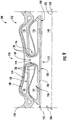
- FIG. 3 provides an end view of the exemplary bearing 100 of FIG. 2
- FIG. 4 provides a perspective, cut-away view of the exemplary bearing 100 of FIG. 2 .
- the exemplary bearing 100 may be incorporated into the exemplary turbofan engine 12 described above with reference to FIG. 1 , or alternatively, the bearing 100 may be incorporated into any other suitable gas turbine engine or turbomachine.
- the exemplary bearing 100 depicted generally defines an axial direction A2 (and a central axis 102 extending generally along the axial direction A2), a radial direction R2, and a circumferential direction C2.
- the bearing 100 defines an axial opening 104 and is configured to support a rotary component, e.g., of the turbofan engine 12, within the axial opening 104.
- the bearing 100 generally includes one or more bearing pads 106, each defining an inner surface 108 for supporting the rotary component and a housing 110 attached to or formed integrally with the bearing pad 106.
- the bearing 100 is configured as an "air" bearing, or oil-free/oil-less bearing, and accordingly the housing 110 is generally configured to provide the inner surfaces 108 of the one or more bearing pads 106 with a flow of a working gas (e.g., air, compressed air and combustion gases, or the like) during operation to create separation with the rotary component and provide a low friction means for supporting such rotary component (not depicted).
- a working gas e.g., air, compressed air and combustion gases, or the like
- the housing 110 of the bearing 100 includes a gas inlet 112 ( FIG. 3 ) at a first end along the axial direction A2 and a supply channel 114 ( FIG. 4 ) extending from the gas inlet 112 to a column 116.
- the column 116 is configured to provide the bearing pad 106 with a flow of the working gas from the supply channel 114, as will be discussed in greater detail below. Additionally, as is depicted, the column 116 extends towards the bearing pad 106 and supports the bearing pad 106. For the embodiment depicted, the column 116 fully supports the bearing pad 106. Further, for the embodiment depicted, the column 116 is located approximately at a center of the bearing pad 106.
- the bearing pad 106 depicted defines a center 118 along the axial direction A2 and along the circumferential direction C2, and the column 116 is at least partially attached to or formed integrally with the bearing pad 106 proximate the center 118 of the bearing pad 106.
- the column 116 may instead be positioned off-center from the bearing pad 106.
- the bearing pad 106 may be configured to disperse and/or diffuse the working gas to support and/or lubricate the rotary component during operation of the bearing 100.
- the bearing 100 may provide a hydrostatically pressurized compliant bearing pad.
- the exemplary bearing pad 106 depicted includes a plurality of gas distribution holes 120 disposed across the bearing pad 106 to provide an evenly distributed pressure field within the axial opening 104 for supporting and/or lubricating the rotary component.
- the plurality of gas distribution holes 120 may be configured having any dimensions or arrangements (e.g., array, pattern or configuration) suitable to function as described herein.
- the plurality of gas distribution holes 120 may generally have a diameter in the range of between about 2 mils (about 50 micrometers) and about 100 mils (about 2,540 micrometers) and, more specifically, between about 5 mils (about 127 micrometers) and about 20 mils (about 508 micrometers).
- each bearing pad 106 may have a sufficiently high gas permeability to permit the working gas received from the column 116 to generate sufficient pressure within axial opening 104 to provide the support and/or lubrication of the rotary component.
- the bearing 100 includes a plurality of sections 122 spaced along the circumferential direction C2 of the bearing 100.
- Each section 122 may generally include a bearing pad 106 (e.g., configured in the same manner described above) and a respective portion of the housing 110 configured as a damper assembly.
- the bearing 100 includes a plurality of bearing pads 106 substantially evenly spaced along the circumferential direction C2.
- Each of the bearing pads 106 defines a respective inner surface 108, the inner surfaces 108 of the plurality of bearing pads 106 together defining a substantially annular support surface along the circumferential direction C2 (see, e.g., FIG. 3 ) and a linear support surface along the axial direction A2 (see, e.g., FIG. 6 , discussed below) for supporting a rotary component.
- the bearing pads 106 may be fabricated from any material suitable to withstand the working conditions of the bearing 100.
- the bearing pads 106 are fabricated form a material having a sufficiently low porosity to prevent instabilities in the thin gas film created between bearing pads 106 and the rotary component during operation of, e.g., the turbomachine.
- the bearing pads 106 may be fabricated from porous carbons, such as carbon graphite, sintered porous ceramics, and sintered porous metals, such as cobalt, nickel, or iron-based alloys.
- each section 122 may be formed integrally of a single, continuous material.
- each of the bearing pads 106 may be formed integrally with the housing 110 of the respective section 122 of the bearing 100, such that the bearing pad 106 and housing 110 of the respective section 122 are fabricated to form a single integral part.
- a plurality of bearing pads 106 and respective portions of the housing 110 forming two or more sections 122 may be formed integrally, or further still, each of the plurality of bearing pads 106 and respective portions of the housing 110 forming the bearing 100 may be formed integrally.
- the bearing pads 106 and housing 110 may be fabricated via any technique suitable to facilitate forming the integral part depicted and described below.
- the bearing pads 106 and the housing 110 may be fabricated using an additive manufacturing process (also known as rapid prototyping, rapid manufacturing, and 3D printing), such as selective laser sintering (SLS), direct metal laser sintering (DMLS), electron beam melting (EBM), diffusion bonding, or selective heat sintering (SHS).
- SLS selective laser sintering
- DMLS direct metal laser sintering
- EBM electron beam melting
- SHS selective heat sintering
- one or more of the bearing sections 122 may be formed integrally of a single, continuous material and joined to separately formed, adjacent bearing sections 122 in any other suitable manner, such as through a mechanical fastening means.
- each of the bearing sections 122 includes a portion of the housing 110 configured as a damper assembly. More particularly, for the embodiment depicted, the housing 110 at least partially defines a first fluid damper cavity 124 and a second fluid damper cavity 126. For the embodiment depicted, the first fluid damper cavity 124 and the second fluid damper cavity 126 each extend three hundred and sixty degrees (360°) around the column 116.
- first fluid damper cavity 124 is positioned adjacent to the bearing pad 106 and the second fluid damper cavity 126 is spaced from the first fluid damper cavity 124, or more particularly, is spaced from the first fluid damper cavity 124 along the radial direction R2.
- the portion of the housing 110 configured as a damper assembly for each bearing section 122 generally includes a first, outer wall 128 and a second, inner wall 130.
- the inner wall 130 and outer wall 128, for the embodiment depicted, are configured as a serpentine inner wall 130 and a serpentine outer wall 128 (i.e., a wall extending in a variety of directions), respectively.
- the bearing pad 106 generally defines an outer periphery 132.
- the serpentine outer wall 128 is attached to or formed integrally with the bearing pad 106 proximate the outer periphery 132 of the bearing pad 106 (or rather, at the outer periphery 132 of the bearing pad 106), extends generally towards the center 118 of the bearing pad 106 along the axial direction A2, and subsequently extends back away from the center 118 of the bearing pad 106 along the axial direction A2, connecting with a body 134 of the housing 110.
- the inner wall 130 is attached to or formed integrally with the bearing pad 106 proximate the center 118 of the bearing pad 106 (or rather, at the center 118 of the bearing pad 106), extends generally away from the bearing pad 106 along the radial direction R2, and subsequently extends away from the center 118 of the bearing pad 106 along the axial direction A2, also connecting with the body 134 of the housing 110.
- the outer wall 128 generally includes a semi-rigid portion 136 and a rigid portion 138, and similarly the inner wall 130 includes a semi-rigid portion 140. As is depicted, the outer wall 128 at least partially defines the first fluid damper cavity 124 and at least partially defines the second fluid damper cavity 126. Additionally, the bearing pad 106 at least partially defines the first fluid damper cavity 124, and the inner wall 130 at least partially defines the second fluid damper cavity 126.
- the semi-rigid portion 136 of the outer wall 128 and bearing pad 106 together define the first fluid damper cavity 124
- the rigid portion 138 of the outer wall 128 and semi-rigid portion 140 of the inner wall 130 together define the second fluid damper cavity 126.
- a portion of a component of the bearing 100 described as semi-rigid may be configured to bend, flex, or give way prior to a portion of a component of the bearing 100 described as rigid.
- the semi-rigid portions of the various components are created by forming such portions with a lesser thickness as compared to the rigid portions of such components.
- a component of the bearing 100 described as “semi-rigid” herein refers to a component configured to bend, flex, or give way during normal operation of the bearing 100 while incurring little or no damage.
- the first fluid damper cavity 124 is in flow communication with the second fluid damper cavity 126 through a portion of the column 116.
- the exemplary column 116 depicted is configured as a double-walled column 116 formed from a portion of the inner wall 130 and a portion of the outer wall 128. Accordingly, the column 116 is supported at a radially outer end by the rigid portion 138 of the outer wall 128 and the semi-rigid portion 140 of the inner wall 130.
- the portion of the column 116 formed by the inner wall 130 is attached to the bearing pad 106 (or rather formed integrally with the bearing pad 106), and the portion of the column 116 formed by the outer wall 128 is attached to the bearing pad 106 through the semi-rigid portion 136 of the outer wall 128.
- the inner wall 130 defines an inner channel 142 for providing the bearing pad 106 with the working gas
- the outer wall 128 and inner wall 130 together define an outer channel 144.
- the outer channel 144 is concentric with the inner channel 142 and defines a substantially annular shape around the inner channel 142.
- the outer channel 144 is configured as a clearance gap, such that the first fluid damper cavity 124 and the second fluid damper cavity 126 are in restrictive flow communication through the outer channel 144.
- first fluid damper cavity 124, second fluid damper cavity 126, and outer channel 144 are all sealed together, and together define a fixed volume.
- the exemplary housing 110 depicted defines a damper cavity supply 146 ( FIG. 6 ) for filling the first and second fluid damper cavities 124, 126 with a dampening fluid, such that during operation, the first and second fluid damper cavities 124, 126 and outer channel 144 are each completely filled with the dampening fluid.
- a cap or other removable or permanent closure means may be positioned over the damper cavity supply 146 after the cavities are filled.
- the dampening fluid may be, e.g., an oil, such as heat transfer oil, or alternatively may be any other suitable fluid, such as any suitable incompressible liquid.
- the bearing 100 is configured to transfer the damper fluid from the first fluid damper cavity 124, through the outer channel 144/clearance gap, and to the second fluid damper cavity 126 in response to a force acting on the bearing pad 106.
- FIGS. 7 and 8 providing side, cross-sectional views of a portion of the exemplary bearing 100.
- FIG. 7 provides a side, close-up, cross-sectional view of the exemplary bearing 100 having absorbed a force acting on the bearing pad 106
- FIG. 8 provides a side, close-up, cross-sectional view of the exemplary bearing 100 without a force acting on the bearing pad 106.
- the portion of the housing 110 forming the damper assembly allows for the bearing pad 106 to move along the radial direction R2, absorbing such force. More particularly, as the column 116 supporting the bearing pad 106 moves up, the semi-rigid portion 136 of the outer wall 128 partially deforms (decreasing a volume of the first fluid damper cavity 124), a portion of the damping fluid within the first fluid damper cavity 124 is forced through the outer channel 144 of the column 116, configured as a clearance gap, and flows into the second fluid damper cavity 126.
- the rigid portion 138 of the outer wall 128 remains substantially stationary, and the semi-rigid portion 140 of the inner wall 130 partially deforms to increase a volume of the second fluid damper cavity 126 and accept the portion of the dampening fluid provided through the outer channel 144 of the column 116 from the first fluid damper cavity 124.
- Such movement absorbs the force exerted on the bearing pad 106, and dampens such movement.
- the relatively tight clearance of the outer channel 144/clearance gap resists relatively quick movement of the bearing pad 106 along the radial direction R2.
- the dampening fluid transferred to the second fluid damper cavity 126 may reverse in flow direction, and flow back through the outer channel 144 of the column 116 to the first fluid damper cavity 124 ( FIG. 8 ).
- FIG. 9 a side, cross-sectional view is provided depicting a bearing 100 accommodating an off-axis rotation of a rotary component 148.
- the rotary component 148 depicted may be, e.g., an LP shaft 36 or HP shaft 34 of the turbofan engine 12 of FIG. 1 .
- a bearing 100 in accordance with one or more embodiments of the present disclosure may be capable of accommodating a misaligned rotary component 148 or other off axis rotations.
- the exemplary semi-rigid column 116 is configured to support the bearing pad 106 from a location inward of the outer periphery 132 of the bearing pad 106 along the axial direction A2, or for the embodiment depicted from a location proximate the center 118 of the bearing pad 106. Accordingly, a resistive force of the bearing pad 106 along the radial direction R2 is much greater proximate the location from which the column 116 supports the bearing pad 106 as compared to, e.g., the outer periphery 132 of the bearing pad 106.
- a resistance of the bearing pad 106 along the radial direction R2 at the outer periphery 132 is less than a resistance of the bearing pad 106 along the radial direction R2 proximate the location from which the column 116 supports the bearing pad 106.
- the exemplary semi-rigid column 116 of the bearing 100 is configured to pivot or bend to accommodate misalignment of a central axis 150 of the rotary component 148 with the central axis 102 of the bearing 100.
- the central axis 150 of the rotary component 148 may define an angle with the central axis 102 of the bearing 100 due to, e.g., improper installation of the bearing 100 or a specific maneuvering of a gas turbine engine into which the bearing 100 is installed.
- the semi-rigid column 116 of the bearing 100 may flex or pivot to allow for the bearing pad 106 accommodate such misalignment.
- the inventors have observed that the above described embodiment of the bearing 100 may lead to a reduction in size and weight. Further, the reduction in size and weight of the bearing 100 may further allow the bearing 100 to be utilized in unconventional locations and/or integrations throughout a turbomachine without disrupting an existing cross section, length or architecture of the turbomachine. Such utilization of the bearing 100 may advantageously benefit engine operation due to reduced clearance closures during maneuver of loads, ability to engineer loner rotor bearing systems with additional stages, reduction in dynamic bearing and structural loads, reduction in synchronous vibration response, and improved stability.
- the inventive bearing advantageously includes one or more integrated parts, thereby reducing a total number of parts that would otherwise be utilized in conventional gas bearing construction, thus reducing weight, complexity, cost and overall size of the bearing as compared to conventional gas bearings.
- FIG. 10 a schematic, cross-sectional, end view of a bearing 100 in accordance with another exemplary embodiment of the present disclosure is provided.
- the bearing 100 depicted in FIG. 10 may be configured in substantially the same manner as the exemplary bearing 100 described above with reference to FIGS. 2 through 9 , and accordingly the same or similar numbers may refer to the same or similar parts. Additionally, the schematic view provided in FIG. 10 may be similar to the view depicted above in FIG. 5 .
- the bearing 100 is generally formed of a plurality of bearing sections 122, each bearing section 122 including a housing 110 and a bearing pad 106 for supporting a rotary component.
- the housing 110 is formed integrally with the bearing pad 106 and defines a first fluid damper cavity 124 and a second fluid damper cavity 126.
- the housing 110 includes a first, outer wall 128 and a second, inner wall 130.
- the outer wall 128 includes a semi-rigid portion 136 and a rigid portion 138, and similarly the inner wall 130 includes a semi-rigid portion 140.
- the outer wall 128 at least partially defines the first fluid damper cavity 124 and at least partially defines the second fluid damper cavity 126.
- the bearing pad 106 at least partially defines the first fluid damper cavity 124
- the inner wall 130 at least partially defines the second fluid damper cavity 126. More particularly, for the embodiment depicted the semi-rigid portion 136 of the outer wall 128 and bearing pad 106 together define the first fluid damper cavity 124, and the rigid portion 138 of the outer wall 128 and semi-rigid portion 140 of the inner wall 130 together define the second fluid damper cavity 126.
- the exemplary column 116 depicted is configured as a double-walled column 116 formed from a portion of the inner wall 130 and a portion of the outer wall 128. Accordingly, the column 116 is supported at a radially outer end by the rigid portion 138 of the outer wall 128 and the semi-rigid portion 140 of the inner wall 130. Further, at a radially inner end the portion of the column 116 formed by the inner wall 130 is attached to the bearing pad 106 (or rather formed integrally with the bearing pad 106), and the portion of the column 116 formed by the outer wall 128 is attached to the bearing pad 106 through the semi-rigid portion 136 of the outer wall 128.
- each bearing section 122 defines a stiffness along the radial direction R2.
- the stiffness of each bearing section 122 may directly relate to a stiffness of the components supporting the bearing pad 106, including the column 116, the semi-rigid portion 140 of the inner wall 130, and the semi-rigid portion 138 of the outer wall 128.
- the stiffness of each bearing section 122 is not identical.
- the stiffness of the bearing sections 122 of the bearing 100 varies in the orthogonal directions (e.g., every ninety degrees), such that a stiffness of a bearing section 122 in a first direction is different than a stiffness of a bearing section 122 in a second direction, the second direction being substantially orthogonal to the first direction.
- the exemplary bearing depicted includes a first bearing section 122A, a second bearing section 122B, a third bearing section 122C, and a fourth bearing section 122D.
- the first and third bearing sections 122A, 122C are located across from one another, and the second and fourth bearing sections 122B, 122D are similarly located across from one another.
- the first and third bearing sections 122A, 122C define a first stiffness, K1
- the second and fourth bearing sections 122B, 122D define a second stiffness, K2.
- the first stiffness K1 is not equal to the second stiffness K2.
- the first stiffness K1 may be at least about five percent (5%) greater, at least about eight percent (8%) greater, at least about ten percent (10%) greater, or at least about fifteen percent (15%) greater than the second stiffness K2.
- Such a configuration may prevent or minimize an amount of circular whirl of the rotary component during operation (relative to the central axis 102). More particularly, such a configuration may result in an elliptical whirl orbit.
- the elliptical whirl may reduce an energy input into a vibratory motion or whirl of the rotary component. Accordingly, such a configuration may allow for higher rotational speed of the rotary component before being susceptible to a rotordynamic instability.
- the exemplary bearing 100 depicted in FIG. 10 is by way of example only. In other embodiments, the bearing 100 may have any other suitable number of sections 122. Additionally, or alternatively, in other embodiments, each bearing section 122 may define an identical stiffness.
Description
- The present subject matter relates generally to a bearing, or more particularly to an air bearing that may be used in a gas turbine engine.
- A gas turbine engine generally includes a fan and a core arranged in flow communication with one another. Additionally, the core of the gas turbine engine general includes, in serial flow order, a compressor section, a combustion section, a turbine section, and an exhaust section. In operation, air is provided from the fan to an inlet of the compressor section where one or more axial compressors progressively compress the air until it reaches the combustion section. Fuel is mixed with the compressed air and burned within the combustion section to provide combustion gases. The combustion gases are routed from the combustion section to the turbine section. The flow of combustion gasses through the turbine section drives the turbine section and is then routed through the exhaust section, e.g., to atmosphere.
- Conventional gas turbine engines include rotor assemblies having shafts, compressors, turbines, couplings, sealing packs, and other elements required for optimal operation under given operating conditions. These rotor assemblies have a mass generating a constant static force due to gravity, and also generate a dynamic force due, e.g., to imbalances in the rotor assembly during operation. Such gas turbine engines include bearings to sustain and support these forces while permitting rotation of the rotor assembly.
- At least some known rotary machines use gas bearings where a non-oil lubricated bearings are desired. However, the inventors have observed that some gas bearings require a substantial number of assembled components to provide the necessary functionality to meet dynamic loading requirements. Such a high number of components introduce high complexity, cost, and weight to the gas bearing, thereby limiting potential applications, especially in aerospace gas turbine engines where weight reduction and space envelope is paramount. Moreover, the high number of components increases a size of the gas bearing without providing additional functionality, thereby preventing the gas bearing from being utilized within space limited locations throughout the gas turbine engines, such as aircraft engines. Also, large number of components may reduce the design reliability of the bearing assembly.
- Therefore, a gas bearing formed of less components would be useful. More particularly, a gas bearing capable of effectively handling static and dynamic forces during operation while having a reduced size and weight would be particularly beneficial.
-
WO 2015/053870 describes journal bearing assemblies that include, amongst other things, a damper assembly.US 2009/0304313 describes a hybrid gas journal bearing using integral wire mesh dampers.WO 2016/085673 A1 describes a thrust bearing including one or more bearing pads, each with a thrust face, attached to a compliant bearing housing. - Aspects and advantages of the invention will be set forth in part in the following description, or may be obvious from the description, or may be learned through practice of the invention.
- In one exemplary embodiment of the present disclosure, a bearing is provided. The bearing includes a bearing pad for supporting a rotary component and a housing. The housing is attached to or formed integrally with the bearing pad. The housing defines a first fluid damper cavity positioned adjacent to the bearing pad, and a second fluid damper cavity spaced from the first fluid damper cavity and in restrictive flow communication with the first fluid damper cavity. The housing is configured to transfer a fluid from the first fluid damper cavity to the second fluid damper cavity in response to a force acting on the bearing pad.
- In another exemplary embodiment of the present disclosure, a bearing is provided for a gas turbine engine comprising a rotary component. The bearing includes a bearing pad for supporting the rotary component of the gas turbine engine, and a housing. The housing includes a serpentine wall attached to or formed integrally with the bearing pad. The serpentine wall at least partially defines a first fluid damper cavity positioned adjacent to the bearing pad and at least partially defines a second fluid damper cavity. The first fluid damper cavity is in restrictive flow communication with the second fluid damper cavity.
- These and other features, aspects and advantages of the present invention will become better understood with reference to the following description and appended claims. The accompanying drawings, which are incorporated in and constitute a part of this specification, illustrate embodiments of the invention and, together with the description, serve to explain the principles of the invention.
- A full and enabling disclosure of the present invention, including the best mode thereof, directed to one of ordinary skill in the art, is set forth in the specification, which makes reference to the appended figures, in which:
-
FIG. 1 is a schematic cross-sectional view of an exemplary gas turbine engine according to various embodiments of the present subject matter. -
FIG. 2 is a side view of a bearing in accordance with an exemplary embodiment of the present disclosure. -
FIG. 3 is an end view of the exemplary bearing ofFIG. 2 . -
FIG. 4 is a perspective, cutaway view of the exemplary bearing ofFIG. 2 . -
FIG. 5 is a cross-sectional view of the exemplary bearing ofFIG. 2 , taken along Line 5-5 inFIG. 2 . -
FIG. 6 is a cross-sectional view of the exemplary bearing ofFIG. 2 , taken along Line 6-6 inFIG. 3 . -
FIG. 7 is a close-up, cross-sectional view of the exemplary bearing ofFIG. 2 , in a depressed state. -
FIG. 8 is a close-up, cross-sectional view of the exemplary bearing ofFIG. 2 , in an extended state. -
FIG. 9 is a close-up, cross-sectional view of the exemplary bearing ofFIG. 2 accommodating an off axis rotary component. -
FIG. 10 is a schematic, cross-sectional, end view of a bearing in accordance with an exemplary embodiment of the present disclosure. - Reference will now be made in detail to present embodiments of the invention, one or more examples of which are illustrated in the accompanying drawings. The detailed description uses numerical and letter designations to refer to features in the drawings. Like or similar designations in the drawings and description have been used to refer to like or similar parts of the invention. As used herein, the terms "first", "second", and "third" may be used interchangeably to distinguish one component from another and are not intended to signify location or importance of the individual components. The terms "upstream" and "downstream" refer to the relative direction with respect to fluid flow in a fluid pathway. For example, "upstream" refers to the direction from which the fluid flows, and "downstream" refers to the direction to which the fluid flows.
- Referring now to the drawings, wherein identical numerals indicate the same elements throughout the figures,
FIG. 1 is a schematic cross-sectional view of a turbomachine in accordance with an exemplary embodiment of the present disclosure. More particularly, for the embodiment ofFIG. 1 , the turbomachine is configured as a gas turbine engine, or rather as a high-bypassturbofan jet engine 12, referred to herein as "turbofan engine 12." As shown inFIG. 1 , theturbofan engine 12 defines an axial direction A (extending parallel to alongitudinal centerline 13 provided for reference), a radial direction R, and a circumferential direction (not shown) extending about the axial direction A. In general, the turbofan 10 includes afan section 14 and acore turbine engine 16 disposed downstream from thefan section 14. - The exemplary
core turbine engine 16 depicted generally includes a substantially tubularouter casing 18 that defines anannular inlet 20. Theouter casing 18 encases and thecore turbine engine 16 includes, in serial flow relationship, a compressor section including a booster or low pressure (LP)compressor 22 and a high pressure (HP)compressor 24; acombustion section 26; a turbine section including a high pressure (HP)turbine 28 and a low pressure (LP)turbine 30; and a jetexhaust nozzle section 32. A high pressure (HP) shaft orspool 34 drivingly connects the HPturbine 28 to the HPcompressor 24. A low pressure (LP) shaft orspool 36 drivingly connects theLP turbine 30 to theLP compressor 22. Accordingly, theLP shaft 36 and HPshaft 34 are each rotary components, rotating about the axial direction A during operation of theturbofan engine 12. - In order to support such rotary components, the turbofan engine includes a plurality of
air bearings 100 attached to various structural components within theturbofan engine 12. Specifically, for the embodiment depicted thebearings 100 facilitate rotation of, e.g., theLP shaft 36 andHP shaft 34 and dampen vibrational energy imparted tobearings 100 during operation of theturbofan engine 12. Although thebearings 100 are described and illustrated as being located generally at forward and aft ends of therespective LP shaft 36 andHP shaft 34, thebearings 100 may additionally, or alternatively, be located at any desired location along theLP shaft 36 andHP shaft 34 including, but not limited to, central or mid-span regions of theshafts shafts conventional bearings 100 would present significant design challenges. Further,bearings 100 may be used in combination with conventional oil-lubricated bearings. For example, in one embodiment, conventional oil-lubricated bearings may be located at the ends ofshafts more bearings 100 may be located along central or mid-span regions ofshafts - Referring still to the embodiment of
FIG. 1 , thefan section 14 includes afan 38 having a plurality offan blades 40 coupled to adisk 42 in a spaced apart manner. As depicted, thefan blades 40 extend outwardly fromdisk 42 generally along the radial direction R. Eachfan blade 40 is rotatable relative to thedisk 42 about a pitch axis P by virtue of thefan blades 40 being operatively coupled to a suitablepitch change mechanism 44 configured to collectively vary the pitch of thefan blades 40 in unison. Thefan blades 40,disk 42, andpitch change mechanism 44 are together rotatable about thelongitudinal axis 12 byLP shaft 36 across apower gear box 46. Thepower gear box 46 includes a plurality of gears for adjusting the rotational speed of thefan 38 relative to theLP shaft 36 to a more efficient rotational fan speed. More particularly, the fan section includes a fan shaft rotatable by theLP shaft 36 across thepower gearbox 46. Accordingly, the fan shaft may also be considered a rotary component, and is similarly supported by one or more bearings. - Referring still to the exemplary embodiment of
FIG. 1 , thedisk 42 is covered by arotatable front hub 48 aerodynamically contoured to promote an airflow through the plurality offan blades 40. Additionally, theexemplary fan section 14 includes an annular fan casing orouter nacelle 50 that circumferentially surrounds thefan 38 and/or at least a portion of thecore turbine engine 16. Theexemplary nacelle 50 is supported relative to thecore turbine engine 16 by a plurality of circumferentially-spaced outlet guide vanes 52. Moreover, adownstream section 54 of thenacelle 50 extends over an outer portion of thecore turbine engine 16 so as to define abypass airflow passage 56 therebetween. - During operation of the
turbofan engine 12, a volume ofair 58 enters the turbofan 10 through an associatedinlet 60 of thenacelle 50 and/orfan section 14. As the volume ofair 58 passes across thefan blades 40, a first portion of theair 58 as indicated byarrows 62 is directed or routed into thebypass airflow passage 56 and a second portion of theair 58 as indicated byarrow 64 is directed or routed into the core air flowpath 37, or more specifically into theLP compressor 22. The ratio between the first portion ofair 62 and the second portion ofair 64 is commonly known as a bypass ratio. The pressure of the second portion ofair 64 is then increased as it is routed through the high pressure (HP)compressor 24 and into thecombustion section 26, where it is mixed with fuel and burned to provide combustion gases 66. - The combustion gases 66 are routed through the
HP turbine 28 where a portion of thermal and/or kinetic energy from the combustion gases 66 is extracted via sequential stages of HP turbine stator vanes 68 that are coupled to theouter casing 18 and HPturbine rotor blades 70 that are coupled to the HP shaft orspool 34, thus causing the HP shaft orspool 34 to rotate, thereby supporting operation of theHP compressor 24. The combustion gases 66 are then routed through theLP turbine 30 where a second portion of thermal and kinetic energy is extracted from the combustion gases 66 via sequential stages of LPturbine stator vanes 72 that are coupled to theouter casing 18 and LPturbine rotor blades 74 that are coupled to the LP shaft orspool 36, thus causing the LP shaft orspool 36 to rotate, thereby supporting operation of theLP compressor 22 and/or rotation of thefan 38. - The combustion gases 66 are subsequently routed through the jet
exhaust nozzle section 32 of thecore turbine engine 16 to provide propulsive thrust. Simultaneously, the pressure of the first portion ofair 62 is substantially increased as the first portion ofair 62 is routed through thebypass airflow passage 56 before it is exhausted from a fannozzle exhaust section 76 of the turbofan 10, also providing propulsive thrust. TheHP turbine 28, theLP turbine 30, and the jetexhaust nozzle section 32 at least partially define ahot gas path 78 for routing the combustion gases 66 through thecore turbine engine 16. - It should be appreciated, however, that the
exemplary turbofan engine 12 depicted inFIG. 1 is provided by way of example only, and that in other exemplary embodiments, theturbofan engine 12 may have any other suitable configuration. It should also be appreciated, that in still other exemplary embodiments, aspects of the present disclosure may be incorporated into any other suitable gas turbine engine. For example, in other exemplary embodiments, aspects of the present disclosure may be incorporated into, e.g., a turboprop engine, a turboshaft engine, or a turbojet engine. Further, in still other embodiments, aspects of the present disclosure may be incorporated into any other suitable turbomachine, including, without limitation, a steam turbine, a centrifugal compressor, and/or a turbocharger. - Referring now to
FIGS. 2 through 4 , abearing 100 in accordance with an exemplary embodiment of the present disclosure is depicted. Specifically,FIG. 2 provides a side view of abearing 100 in accordance with an exemplary embodiment of the present disclosure;FIG. 3 provides an end view of theexemplary bearing 100 ofFIG. 2 ; andFIG. 4 provides a perspective, cut-away view of theexemplary bearing 100 ofFIG. 2 . In certain exemplary embodiments, theexemplary bearing 100 may be incorporated into theexemplary turbofan engine 12 described above with reference toFIG. 1 , or alternatively, thebearing 100 may be incorporated into any other suitable gas turbine engine or turbomachine. - As shown, the
exemplary bearing 100 depicted generally defines an axial direction A2 (and acentral axis 102 extending generally along the axial direction A2), a radial direction R2, and a circumferential direction C2. Thebearing 100 defines anaxial opening 104 and is configured to support a rotary component, e.g., of theturbofan engine 12, within theaxial opening 104. The bearing 100 generally includes one ormore bearing pads 106, each defining aninner surface 108 for supporting the rotary component and ahousing 110 attached to or formed integrally with thebearing pad 106. Thebearing 100 is configured as an "air" bearing, or oil-free/oil-less bearing, and accordingly thehousing 110 is generally configured to provide theinner surfaces 108 of the one ormore bearing pads 106 with a flow of a working gas (e.g., air, compressed air and combustion gases, or the like) during operation to create separation with the rotary component and provide a low friction means for supporting such rotary component (not depicted). - The
housing 110 of thebearing 100 includes a gas inlet 112 (FIG. 3 ) at a first end along the axial direction A2 and a supply channel 114 (FIG. 4 ) extending from thegas inlet 112 to acolumn 116. Thecolumn 116 is configured to provide thebearing pad 106 with a flow of the working gas from thesupply channel 114, as will be discussed in greater detail below. Additionally, as is depicted, thecolumn 116 extends towards the bearingpad 106 and supports thebearing pad 106. For the embodiment depicted, thecolumn 116 fully supports thebearing pad 106. Further, for the embodiment depicted, thecolumn 116 is located approximately at a center of thebearing pad 106. More particularly, thebearing pad 106 depicted defines acenter 118 along the axial direction A2 and along the circumferential direction C2, and thecolumn 116 is at least partially attached to or formed integrally with thebearing pad 106 proximate thecenter 118 of thebearing pad 106. However, in other embodiments, thecolumn 116 may instead be positioned off-center from thebearing pad 106. - In certain embodiments, the
bearing pad 106 may be configured to disperse and/or diffuse the working gas to support and/or lubricate the rotary component during operation of thebearing 100. In such manner, thebearing 100 may provide a hydrostatically pressurized compliant bearing pad. For example, theexemplary bearing pad 106 depicted includes a plurality of gas distribution holes 120 disposed across thebearing pad 106 to provide an evenly distributed pressure field within theaxial opening 104 for supporting and/or lubricating the rotary component. - The plurality of gas distribution holes 120 may be configured having any dimensions or arrangements (e.g., array, pattern or configuration) suitable to function as described herein. For example, in some embodiments, the plurality of gas distribution holes 120 may generally have a diameter in the range of between about 2 mils (about 50 micrometers) and about 100 mils (about 2,540 micrometers) and, more specifically, between about 5 mils (about 127 micrometers) and about 20 mils (about 508 micrometers). Alternatively, or in addition, in some embodiments, each
bearing pad 106 may have a sufficiently high gas permeability to permit the working gas received from thecolumn 116 to generate sufficient pressure withinaxial opening 104 to provide the support and/or lubrication of the rotary component. - Furthermore, as is depicted, the
bearing 100 includes a plurality ofsections 122 spaced along the circumferential direction C2 of thebearing 100. Eachsection 122 may generally include a bearing pad 106 (e.g., configured in the same manner described above) and a respective portion of thehousing 110 configured as a damper assembly. Accordingly, as may be seen most clearly in, e.g.,FIG. 3 , thebearing 100 includes a plurality of bearingpads 106 substantially evenly spaced along the circumferential direction C2. Each of the bearingpads 106 defines a respectiveinner surface 108, theinner surfaces 108 of the plurality of bearingpads 106 together defining a substantially annular support surface along the circumferential direction C2 (see, e.g.,FIG. 3 ) and a linear support surface along the axial direction A2 (see, e.g.,FIG. 6 , discussed below) for supporting a rotary component. - The bearing
pads 106 may be fabricated from any material suitable to withstand the working conditions of thebearing 100. In addition, in some embodiments, the bearingpads 106 are fabricated form a material having a sufficiently low porosity to prevent instabilities in the thin gas film created between bearingpads 106 and the rotary component during operation of, e.g., the turbomachine. For example, in some embodiments, the bearingpads 106 may be fabricated from porous carbons, such as carbon graphite, sintered porous ceramics, and sintered porous metals, such as cobalt, nickel, or iron-based alloys. - Moreover, in some embodiments, the
bearing pad 106 andhousing 110 of eachsection 122 may be formed integrally of a single, continuous material. For example, in some embodiments, each of the bearingpads 106 may be formed integrally with thehousing 110 of therespective section 122 of thebearing 100, such that thebearing pad 106 andhousing 110 of therespective section 122 are fabricated to form a single integral part. Moreover, in certain embodiments, a plurality of bearingpads 106 and respective portions of thehousing 110 forming two ormore sections 122 may be formed integrally, or further still, each of the plurality of bearingpads 106 and respective portions of thehousing 110 forming thebearing 100 may be formed integrally. - The bearing
pads 106 andhousing 110 may be fabricated via any technique suitable to facilitate forming the integral part depicted and described below. For example, in some embodiments, the bearingpads 106 and thehousing 110 may be fabricated using an additive manufacturing process (also known as rapid prototyping, rapid manufacturing, and 3D printing), such as selective laser sintering (SLS), direct metal laser sintering (DMLS), electron beam melting (EBM), diffusion bonding, or selective heat sintering (SHS). It should be appreciated, however, that in other embodiments one or more of the bearingsections 122, including abearing pad 106 and a respective portion of thehousing 110, may be formed integrally of a single, continuous material and joined to separately formed, adjacent bearingsections 122 in any other suitable manner, such as through a mechanical fastening means. - Referring now particularly to
FIG. 4 , and now also toFIGS. 5 and6 providing cross-sectional views of the exemplary bearing 100 (along Line 5-5 inFIG. 2 and along Line 6-6 inFIG. 3 , respectively), as briefly noted above each of the bearingsections 122 includes a portion of thehousing 110 configured as a damper assembly. More particularly, for the embodiment depicted, thehousing 110 at least partially defines a firstfluid damper cavity 124 and a secondfluid damper cavity 126. For the embodiment depicted, the firstfluid damper cavity 124 and the secondfluid damper cavity 126 each extend three hundred and sixty degrees (360°) around thecolumn 116. Additionally, the firstfluid damper cavity 124 is positioned adjacent to thebearing pad 106 and the secondfluid damper cavity 126 is spaced from the firstfluid damper cavity 124, or more particularly, is spaced from the firstfluid damper cavity 124 along the radial direction R2. - For the embodiment depicted, the portion of the
housing 110 configured as a damper assembly for eachbearing section 122 generally includes a first,outer wall 128 and a second,inner wall 130. Theinner wall 130 andouter wall 128, for the embodiment depicted, are configured as a serpentineinner wall 130 and a serpentine outer wall 128 (i.e., a wall extending in a variety of directions), respectively. For example, thebearing pad 106 generally defines anouter periphery 132. The serpentineouter wall 128 is attached to or formed integrally with thebearing pad 106 proximate theouter periphery 132 of the bearing pad 106 (or rather, at theouter periphery 132 of the bearing pad 106), extends generally towards thecenter 118 of thebearing pad 106 along the axial direction A2, and subsequently extends back away from thecenter 118 of thebearing pad 106 along the axial direction A2, connecting with abody 134 of thehousing 110. Similarly, for the embodiment depicted, theinner wall 130 is attached to or formed integrally with thebearing pad 106 proximate thecenter 118 of the bearing pad 106 (or rather, at thecenter 118 of the bearing pad 106), extends generally away from thebearing pad 106 along the radial direction R2, and subsequently extends away from thecenter 118 of thebearing pad 106 along the axial direction A2, also connecting with thebody 134 of thehousing 110. - Further, the
outer wall 128 generally includes asemi-rigid portion 136 and arigid portion 138, and similarly theinner wall 130 includes asemi-rigid portion 140. As is depicted, theouter wall 128 at least partially defines the firstfluid damper cavity 124 and at least partially defines the secondfluid damper cavity 126. Additionally, thebearing pad 106 at least partially defines the firstfluid damper cavity 124, and theinner wall 130 at least partially defines the secondfluid damper cavity 126. More particularly, for the embodiment depicted thesemi-rigid portion 136 of theouter wall 128 andbearing pad 106 together define the firstfluid damper cavity 124, and therigid portion 138 of theouter wall 128 andsemi-rigid portion 140 of theinner wall 130 together define the secondfluid damper cavity 126. - It should be appreciated, that as used herein, the terms "semi-rigid" and "rigid" are relative terms. Accordingly, a portion of a component of the
bearing 100 described as semi-rigid may be configured to bend, flex, or give way prior to a portion of a component of thebearing 100 described as rigid. For the embodiment depicted, the semi-rigid portions of the various components are created by forming such portions with a lesser thickness as compared to the rigid portions of such components. Further, a component of thebearing 100 described as "semi-rigid" herein refers to a component configured to bend, flex, or give way during normal operation of thebearing 100 while incurring little or no damage. - Additionally, for the embodiment depicted the first
fluid damper cavity 124 is in flow communication with the secondfluid damper cavity 126 through a portion of thecolumn 116. Specifically, theexemplary column 116 depicted is configured as a double-walled column 116 formed from a portion of theinner wall 130 and a portion of theouter wall 128. Accordingly, thecolumn 116 is supported at a radially outer end by therigid portion 138 of theouter wall 128 and thesemi-rigid portion 140 of theinner wall 130. Further, at a radially inner end the portion of thecolumn 116 formed by theinner wall 130 is attached to the bearing pad 106 (or rather formed integrally with the bearing pad 106), and the portion of thecolumn 116 formed by theouter wall 128 is attached to thebearing pad 106 through thesemi-rigid portion 136 of theouter wall 128. - Moreover, the
inner wall 130 defines aninner channel 142 for providing thebearing pad 106 with the working gas, and theouter wall 128 andinner wall 130 together define anouter channel 144. As will be appreciated, for the embodiment depicted, theouter channel 144 is concentric with theinner channel 142 and defines a substantially annular shape around theinner channel 142. Further, for the embodiment depicted, theouter channel 144 is configured as a clearance gap, such that the firstfluid damper cavity 124 and the secondfluid damper cavity 126 are in restrictive flow communication through theouter channel 144. - Further, the first
fluid damper cavity 124, secondfluid damper cavity 126, andouter channel 144 are all sealed together, and together define a fixed volume. Theexemplary housing 110 depicted defines a damper cavity supply 146 (FIG. 6 ) for filling the first and secondfluid damper cavities fluid damper cavities outer channel 144 are each completely filled with the dampening fluid. A cap or other removable or permanent closure means may be positioned over thedamper cavity supply 146 after the cavities are filled. The dampening fluid may be, e.g., an oil, such as heat transfer oil, or alternatively may be any other suitable fluid, such as any suitable incompressible liquid. Thebearing 100 is configured to transfer the damper fluid from the firstfluid damper cavity 124, through theouter channel 144/clearance gap, and to the secondfluid damper cavity 126 in response to a force acting on thebearing pad 106. - More particularly, reference will now be made to
FIGS. 7 and 8 , providing side, cross-sectional views of a portion of theexemplary bearing 100.FIG. 7 provides a side, close-up, cross-sectional view of theexemplary bearing 100 having absorbed a force acting on thebearing pad 106, andFIG. 8 provides a side, close-up, cross-sectional view of theexemplary bearing 100 without a force acting on thebearing pad 106. - When a force acts on the
bearing pad 106, such as when a rotary component supported by the bearing 100 presses on thebearing pad 106 generally along the radial direction R2, the portion of thehousing 110 forming the damper assembly allows for thebearing pad 106 to move along the radial direction R2, absorbing such force. More particularly, as thecolumn 116 supporting thebearing pad 106 moves up, thesemi-rigid portion 136 of theouter wall 128 partially deforms (decreasing a volume of the first fluid damper cavity 124), a portion of the damping fluid within the firstfluid damper cavity 124 is forced through theouter channel 144 of thecolumn 116, configured as a clearance gap, and flows into the secondfluid damper cavity 126. At the same time, therigid portion 138 of theouter wall 128 remains substantially stationary, and thesemi-rigid portion 140 of theinner wall 130 partially deforms to increase a volume of the secondfluid damper cavity 126 and accept the portion of the dampening fluid provided through theouter channel 144 of thecolumn 116 from the firstfluid damper cavity 124. Such movement absorbs the force exerted on thebearing pad 106, and dampens such movement. For example, the relatively tight clearance of theouter channel 144/clearance gap resists relatively quick movement of thebearing pad 106 along the radial direction R2. In the absence of the force exerted on thebearing pad 106, the dampening fluid transferred to the secondfluid damper cavity 126 may reverse in flow direction, and flow back through theouter channel 144 of thecolumn 116 to the first fluid damper cavity 124 (FIG. 8 ). - Moreover, referring now to
FIG. 9 , a side, cross-sectional view is provided depicting abearing 100 accommodating an off-axis rotation of arotary component 148. Therotary component 148 depicted may be, e.g., anLP shaft 36 orHP shaft 34 of theturbofan engine 12 ofFIG. 1 . As is discussed herein, abearing 100 in accordance with one or more embodiments of the present disclosure may be capable of accommodating amisaligned rotary component 148 or other off axis rotations. More particularly, the exemplarysemi-rigid column 116 is configured to support thebearing pad 106 from a location inward of theouter periphery 132 of thebearing pad 106 along the axial direction A2, or for the embodiment depicted from a location proximate thecenter 118 of thebearing pad 106. Accordingly, a resistive force of thebearing pad 106 along the radial direction R2 is much greater proximate the location from which thecolumn 116 supports thebearing pad 106 as compared to, e.g., theouter periphery 132 of thebearing pad 106. Specifically, a resistance of thebearing pad 106 along the radial direction R2 at theouter periphery 132 is less than a resistance of thebearing pad 106 along the radial direction R2 proximate the location from which thecolumn 116 supports thebearing pad 106. Accordingly, the exemplarysemi-rigid column 116 of thebearing 100 is configured to pivot or bend to accommodate misalignment of acentral axis 150 of therotary component 148 with thecentral axis 102 of thebearing 100. For example, thecentral axis 150 of therotary component 148 may define an angle with thecentral axis 102 of thebearing 100 due to, e.g., improper installation of thebearing 100 or a specific maneuvering of a gas turbine engine into which thebearing 100 is installed. Thesemi-rigid column 116 of thebearing 100 may flex or pivot to allow for thebearing pad 106 accommodate such misalignment. - Furthermore, the inventors have observed that the above described embodiment of the
bearing 100 may lead to a reduction in size and weight. Further, the reduction in size and weight of thebearing 100 may further allow thebearing 100 to be utilized in unconventional locations and/or integrations throughout a turbomachine without disrupting an existing cross section, length or architecture of the turbomachine. Such utilization of thebearing 100 may advantageously benefit engine operation due to reduced clearance closures during maneuver of loads, ability to engineer loner rotor bearing systems with additional stages, reduction in dynamic bearing and structural loads, reduction in synchronous vibration response, and improved stability. - Thus, embodiments of a bearing having integrally formed components have been provided herein. In at least some embodiments, the inventive bearing advantageously includes one or more integrated parts, thereby reducing a total number of parts that would otherwise be utilized in conventional gas bearing construction, thus reducing weight, complexity, cost and overall size of the bearing as compared to conventional gas bearings.
- Referring now to
FIG. 10 , a schematic, cross-sectional, end view of abearing 100 in accordance with another exemplary embodiment of the present disclosure is provided. The bearing 100 depicted inFIG. 10 may be configured in substantially the same manner as theexemplary bearing 100 described above with reference toFIGS. 2 through 9 , and accordingly the same or similar numbers may refer to the same or similar parts. Additionally, the schematic view provided inFIG. 10 may be similar to the view depicted above inFIG. 5 . - As is depicted, the
bearing 100 is generally formed of a plurality of bearingsections 122, each bearingsection 122 including ahousing 110 and abearing pad 106 for supporting a rotary component. For the embodiment depicted, thehousing 110 is formed integrally with thebearing pad 106 and defines a firstfluid damper cavity 124 and a secondfluid damper cavity 126. More particularly, thehousing 110 includes a first,outer wall 128 and a second,inner wall 130. Theouter wall 128 includes asemi-rigid portion 136 and arigid portion 138, and similarly theinner wall 130 includes asemi-rigid portion 140. As is depicted, theouter wall 128 at least partially defines the firstfluid damper cavity 124 and at least partially defines the secondfluid damper cavity 126. Additionally, thebearing pad 106 at least partially defines the firstfluid damper cavity 124, and theinner wall 130 at least partially defines the secondfluid damper cavity 126. More particularly, for the embodiment depicted thesemi-rigid portion 136 of theouter wall 128 andbearing pad 106 together define the firstfluid damper cavity 124, and therigid portion 138 of theouter wall 128 andsemi-rigid portion 140 of theinner wall 130 together define the secondfluid damper cavity 126. - Additionally, the
exemplary column 116 depicted is configured as a double-walled column 116 formed from a portion of theinner wall 130 and a portion of theouter wall 128. Accordingly, thecolumn 116 is supported at a radially outer end by therigid portion 138 of theouter wall 128 and thesemi-rigid portion 140 of theinner wall 130. Further, at a radially inner end the portion of thecolumn 116 formed by theinner wall 130 is attached to the bearing pad 106 (or rather formed integrally with the bearing pad 106), and the portion of thecolumn 116 formed by theouter wall 128 is attached to thebearing pad 106 through thesemi-rigid portion 136 of theouter wall 128. - Furthermore, it should thus be appreciated, that each bearing
section 122 defines a stiffness along the radial direction R2. The stiffness of each bearingsection 122 may directly relate to a stiffness of the components supporting thebearing pad 106, including thecolumn 116, thesemi-rigid portion 140 of theinner wall 130, and thesemi-rigid portion 138 of theouter wall 128. Notably, for the embodiment depicted, the stiffness of each bearingsection 122 is not identical. More specifically, for the embodiment depicted, the stiffness of the bearingsections 122 of thebearing 100 varies in the orthogonal directions (e.g., every ninety degrees), such that a stiffness of abearing section 122 in a first direction is different than a stiffness of abearing section 122 in a second direction, the second direction being substantially orthogonal to the first direction. - For example, the exemplary bearing depicted includes a
first bearing section 122A, asecond bearing section 122B, athird bearing section 122C, and afourth bearing section 122D. The first andthird bearing sections fourth bearing sections third bearing sections fourth bearing sections - Such a configuration may prevent or minimize an amount of circular whirl of the rotary component during operation (relative to the central axis 102). More particularly, such a configuration may result in an elliptical whirl orbit. The elliptical whirl may reduce an energy input into a vibratory motion or whirl of the rotary component. Accordingly, such a configuration may allow for higher rotational speed of the rotary component before being susceptible to a rotordynamic instability. It should be appreciated, however, that the
exemplary bearing 100 depicted inFIG. 10 is by way of example only. In other embodiments, thebearing 100 may have any other suitable number ofsections 122. Additionally, or alternatively, in other embodiments, each bearingsection 122 may define an identical stiffness. - This written description uses examples to disclose the invention, including the best mode, and also to enable any person skilled in the art to practice the invention, including making and using any devices or systems and performing any incorporated methods. The patentable scope of the invention is defined by the claims, and may include other examples that occur to those skilled in the art. Such other examples are intended to be within the scope of the claims if they include structural elements that do not differ from the literal language of the claims, or if they include equivalent structural elements with insubstantial differences from the literal languages of the claims.
Claims (15)
- A bearing (100) comprising:a bearing pad (106) for supporting a rotary component (148); anda housing (110) attached to or formed integrally with the bearing pad (106), characterized in that the housing (110) definesa first fluid damper cavity (124) positioned adjacent to the bearing pad (106); anda second fluid damper cavity (126) spaced from the first fluid damper cavity (124) and in restrictive flow communication with the first fluid damper cavity (124), the housing (110) being configured to transfer a fluid from the first fluid damper cavity (124) to the second fluid damper cavity (126) in response to forces acting on the bearing pad (106).
- The bearing (100) of claim 1, wherein the bearing pad (106) at least partially defines the first fluid damper cavity (124).
- The bearing (100) of claim 1, wherein the housing (110) comprises a first wall comprising a semi-rigid portion, and wherein the semi-rigid portion of the first wall at least partially defines the first fluid damper cavity (124).
- The bearing (100) of claim 3, wherein the first wall further comprises a rigid portion, and wherein the rigid portion of the first wall at least partially defines the second fluid damper cavity (126).
- The bearing (100) of claim 3, wherein the housing (110) further comprises a second wall comprising a semi-rigid portion, and wherein the semi-rigid portion of the second wall at least partially defines the second fluid damper cavity (126).
- The bearing (100) of claim 1, wherein the first fluid damper cavity (124) and second fluid damper cavity (126) are in restrictive flow communication through a channel (144) configured as a clearance gap.
- The bearing (100) of claim 6, wherein the first fluid damper cavity (124), second fluid damper cavity (126), and channel are sealed together and together define a fixed volume.
- The bearing (100) of claim 1, wherein the bearing (100) defines a radial direction (R2), and wherein the first fluid damper cavity (124) is spaced from the second fluid damper cavity (126) along the radial direction (R2).
- The bearing (100) of claim 1, wherein the bearing pad (106) and housing (110) are formed integrally of a single, continuous material.
- The bearing (100) of claim 9, wherein the bearing pad (106) and housing (110) are formed using a direct metal laser sintering manufacturing process.
- The bearing (100) of claim 1, wherein the bearing (100) defines a circumferential direction (C2), and wherein the bearing (100) further comprise a plurality of bearing pads (106) spaced along the circumferential direction (C2).
- The bearing (100) of claim 1, wherein the housing (110) comprises a semi-rigid column (116) extending towards the bearing pad (106) for providing the bearing pad (106) with an airflow and fully supporting the bearing pad (106).
- The bearing (100) of claim 12, wherein the column (116) defines an inner channel (142) for providing the bearing pad (106) with the airflow and an outer channel (144), wherein the first fluid damper cavity (124) is in restrictive flow communication with the second fluid damper cavity (126) through the outer channel (144).
- The bearing (100) of claim 13, wherein the outer channel (144) is concentric with the inner channel (142).
- The bearing (100) of claim 1, wherein the bearing (100) defines a circumferential direction (C2) and a radial direction (R2), wherein the bearing (100) further comprises:
a plurality of bearing (100) sections spaced along the circumferential direction (C2), wherein each bearing (100) section comprises a bearing pad (106) for supporting the rotary component (148), wherein each bearing (100) section defines a stiffness, and wherein the stiffnesses of the bearing (100) sections vary in orthogonal directions.
Applications Claiming Priority (1)
| Application Number | Priority Date | Filing Date | Title |
|---|---|---|---|
| US15/131,113 US9746029B1 (en) | 2016-04-18 | 2016-04-18 | Bearing |
Publications (2)
| Publication Number | Publication Date |
|---|---|
| EP3236095A1 EP3236095A1 (en) | 2017-10-25 |
| EP3236095B1 true EP3236095B1 (en) | 2019-12-18 |
Family
ID=58544780
Family Applications (1)
| Application Number | Title | Priority Date | Filing Date |
|---|---|---|---|
| EP17165706.7A Active EP3236095B1 (en) | 2016-04-18 | 2017-04-10 | Bearing |
Country Status (5)
| Country | Link |
|---|---|
| US (1) | US9746029B1 (en) |
| EP (1) | EP3236095B1 (en) |
| JP (1) | JP2017201208A (en) |
| CN (1) | CN107448477B (en) |
| CA (1) | CA2963409A1 (en) |
Families Citing this family (18)
| Publication number | Priority date | Publication date | Assignee | Title |
|---|---|---|---|---|
| US9951811B2 (en) | 2016-04-18 | 2018-04-24 | General Electric Company | Bearing |
| EP3324062A1 (en) * | 2016-11-22 | 2018-05-23 | Fischer Engineering Solutions AG | Rotation system with radial gas bearing |
| US11407034B2 (en) | 2017-07-06 | 2022-08-09 | OmniTek Technology Ltda. | Selective laser melting system and method of using same |
| CN107893814A (en) * | 2017-11-14 | 2018-04-10 | 如皋市非标轴承有限公司 | A kind of air bearing |
| US10982713B2 (en) | 2018-03-23 | 2021-04-20 | General Electric Company | Closed cycle heat engine |
| CN108402995A (en) * | 2018-05-14 | 2018-08-17 | 珠海格力电器股份有限公司 | A kind of device with liquid capsule noise reduction shock-damping structure and with its dust catcher |
| US10801549B2 (en) | 2018-05-31 | 2020-10-13 | General Electric Company | Axial load management system |
| US10774873B2 (en) * | 2018-06-11 | 2020-09-15 | Trane International Inc. | Porous gas bearing |
| CN113167329B (en) * | 2018-11-20 | 2023-07-04 | 迪傲公司 | Bearing assembly |
| US10816035B2 (en) | 2018-12-18 | 2020-10-27 | General Electric Company | Hermetic squeeze film damper having an elliptical damper orifice |
| US10815831B2 (en) | 2018-12-18 | 2020-10-27 | General Electric Company | Bearing support including hermetic squeeze film damper and accumulator volume |
| IT201900000635A1 (en) * | 2019-01-15 | 2020-07-15 | Nuovo Pignone Tecnologie Srl | A COMPONENT OF DAMPED CUSHION, CUSHION INCLUDING SAID COMPONENT, AND ROTATING MACHINE INCLUDING SAID CUSHION |
| US11391179B2 (en) | 2019-02-12 | 2022-07-19 | Pratt & Whitney Canada Corp. | Gas turbine engine with bearing support structure |
| US11346249B2 (en) | 2019-03-05 | 2022-05-31 | Pratt & Whitney Canada Corp. | Gas turbine engine with feed pipe for bearing housing |
| US11473448B2 (en) | 2019-07-06 | 2022-10-18 | General Electric Company | Externally pressurized fluid-film bearing system including hermetic fluid damper with pass-through channels |
| US11092036B2 (en) | 2020-01-16 | 2021-08-17 | Raytheon Technologies Corporation | Gas damper and bearing in a propulsion system |
| US11674397B2 (en) * | 2020-11-18 | 2023-06-13 | General Electric Company | Variable stiffness damper system |
| US11879498B2 (en) * | 2021-01-04 | 2024-01-23 | General Electric Company | Rotor damping devices for a turbomachine |
Citations (1)
| Publication number | Priority date | Publication date | Assignee | Title |
|---|---|---|---|---|
| WO2016085673A1 (en) * | 2014-11-25 | 2016-06-02 | General Electric Company | Compliant hybrid gas lubricated thrust bearing |
Family Cites Families (67)
| Publication number | Priority date | Publication date | Assignee | Title |
|---|---|---|---|---|
| US2972504A (en) | 1957-07-22 | 1961-02-21 | Timken Roller Bearing Co | Bearing thrust loader and seal |
| US3110526A (en) | 1961-10-12 | 1963-11-12 | Gen Electric | Bearing support |
| US3721479A (en) | 1971-05-19 | 1973-03-20 | Atomic Energy Commission | Gas bearing and method of making same |
| US3863996A (en) | 1973-06-27 | 1975-02-04 | Westinghouse Electric Corp | Vibration damper bearing |
| US3994541A (en) | 1975-10-03 | 1976-11-30 | Carrier Corporation | Bearing assembly |
| US5137373A (en) | 1987-05-29 | 1992-08-11 | Ide Russell D | Bearings having beam mounted bearing pads and methods of making same |
| US4262975A (en) | 1979-10-01 | 1981-04-21 | Mechanical Technology Incorporated | Compliant journal bearing with angular stiffness gradient |
| US4410220A (en) | 1980-03-17 | 1983-10-18 | The Boeing Company | Gas lubricated ball bearing |
| US4793722A (en) | 1984-08-14 | 1988-12-27 | Elliott Turbomachinery Co., Inc. | Flexible damped bearing assembly |
| US4872767A (en) | 1985-04-03 | 1989-10-10 | General Electric Company | Bearing support |
| DE3544392A1 (en) | 1985-12-14 | 1987-06-19 | Kloeckner Humboldt Deutz Ag | AERODYNAMIC SLIDING BEARING |
| US5421655A (en) | 1987-05-29 | 1995-06-06 | Kmc, Inc. | Fluid dampened support having variable stiffness and damping |
| US5603574A (en) | 1987-05-29 | 1997-02-18 | Kmc, Inc. | Fluid dampened support having variable stiffness and damping |
| US5743654A (en) | 1987-05-29 | 1998-04-28 | Kmc, Inc. | Hydrostatic and active control movable pad bearing |
| JPH0244139U (en) * | 1988-09-21 | 1990-03-27 | ||
| US4971458A (en) | 1989-10-04 | 1990-11-20 | United Technologies Corporation | Fluid damper and spring |
| US5044781A (en) * | 1990-07-26 | 1991-09-03 | United Technologies Corporation | Spring supported damping system |
| US5085521A (en) | 1991-01-14 | 1992-02-04 | General Electric Company | Squeeze film damper seal |
| US5149206A (en) | 1991-04-17 | 1992-09-22 | General Electric Company | Hydraulic shaft damper pressure control |
| DE4121746C2 (en) | 1991-07-01 | 1996-02-22 | Wolf Woco & Co Franz J | Tilger |
| DE4317062C2 (en) | 1993-05-21 | 1995-08-17 | Freudenberg Carl Fa | Cardan shaft bearing |
| US5380100A (en) * | 1994-02-04 | 1995-01-10 | Yu; Han J. | Squeeze film damper covered by torus shells |
| US5374129A (en) | 1994-03-15 | 1994-12-20 | General Electric Co. | Hydrostatic bearing support affording high static and low dynamic stiffness to a rotor in turbomachinery |
| JPH1113764A (en) | 1997-06-23 | 1999-01-22 | Ntn Corp | Hydrostatic air bearing |
| JP2001527180A (en) | 1997-12-20 | 2001-12-25 | アライド・シグナル・インコーポレーテツド | Control of constant internal temperature of turbine in power generation system of microturbine |
| US5924187A (en) | 1998-01-06 | 1999-07-20 | Hutchinson Technology Incorporated | Integrated lead head suspension assembly having an etched laminated load beam and flexure with deposited conductors |
| JP3659008B2 (en) * | 1998-08-07 | 2005-06-15 | 東海ゴム工業株式会社 | Dynamic damper and manufacturing method thereof |
| JP2001050267A (en) * | 1999-08-10 | 2001-02-23 | Hitachi Ltd | Damping bearing and rotary machine using same |
| JP2001090726A (en) * | 1999-09-22 | 2001-04-03 | Mitsubishi Heavy Ind Ltd | Fluid bearing |
| US8834027B2 (en) | 2011-01-13 | 2014-09-16 | Fouad Y. Zeidan | Damper having modular flexible ligaments and variable gaps |
| US6536565B2 (en) | 2001-03-06 | 2003-03-25 | Delphi Technologies, Inc. | Rotary damper |
| US6679045B2 (en) | 2001-12-18 | 2004-01-20 | General Electric Company | Flexibly coupled dual shell bearing housing |
| EP1350972A3 (en) * | 2002-04-04 | 2004-06-23 | Dana Corporation | Cardan shaft center bearing assembly including a support member containing a rheological fluid |
| JP2005032818A (en) | 2003-07-08 | 2005-02-03 | Canon Inc | Hydrostatic bearing, pointing device and aligner |
| US7214037B2 (en) | 2004-06-28 | 2007-05-08 | Honeywell International, Inc. | Retention of ball bearing cartridge for turbomachinery |
| JP3636329B1 (en) | 2004-08-17 | 2005-04-06 | 川崎重工業株式会社 | Bearing vibration damping mechanism |
| US7394076B2 (en) | 2004-08-18 | 2008-07-01 | New Way Machine Components, Inc. | Moving vacuum chamber stage with air bearing and differentially pumped grooves |
| US20060054660A1 (en) | 2004-09-10 | 2006-03-16 | Honeywell International Inc. | Articulated gas bearing support pads |
| JP2006266437A (en) * | 2005-03-25 | 2006-10-05 | Hitachi Ltd | Journal bearing |
| WO2007035298A2 (en) | 2005-09-09 | 2007-03-29 | Lugg Richard H | Advanced hypersonic magnetic jet/electric turbine engine |
| US7625121B2 (en) * | 2005-09-28 | 2009-12-01 | Elliott Company | Bearing assembly and centering support structure therefor |
| WO2007047976A1 (en) | 2005-10-20 | 2007-04-26 | Dresser-Rand Company | Support device for bearing assemblies |
| US7896550B1 (en) | 2006-05-04 | 2011-03-01 | Florida Turbine Technologies, Inc. | Hydrodynamic liquid metal bearing |
| US7431504B1 (en) | 2006-05-18 | 2008-10-07 | Florida Turbine Technologies, Inc. | High temperature damper for a roller bearing |
| US7517152B1 (en) * | 2006-09-20 | 2009-04-14 | Florida Turbine Technologies, Inc. | Squeeze film damper with variable support stiffness |
| US8083413B2 (en) | 2007-10-23 | 2011-12-27 | General Electric Company | Compliant hybrid gas journal bearing using integral wire mesh dampers |
| US8118570B2 (en) | 2007-10-31 | 2012-02-21 | Honeywell International Inc. | Anisotropic bearing supports for turbochargers |
| US8146369B2 (en) | 2007-11-06 | 2012-04-03 | Borealis Technical Limited | Integrated direct drive starter/generator for turbines |
| FR2926604B1 (en) | 2008-01-23 | 2010-03-26 | Snecma | CENTERING A WORKPIECE WITHIN A ROTOR SHAFT IN A TURBOMACHINE |
| US8342796B2 (en) | 2008-04-29 | 2013-01-01 | Honeywell International Inc. | Damping systems for use in engines |
| CN101749322A (en) * | 2008-12-05 | 2010-06-23 | 通用电气公司 | Self-adapting mixed gas radial journal bearing using integral silk net damper |
| US8256750B2 (en) | 2009-02-18 | 2012-09-04 | Honeywell International Inc. | Vibration isolation mounting assembly |
| US8272786B2 (en) | 2009-02-18 | 2012-09-25 | Honeywell International Inc. | Vibration isolation mounting assembly |
| IT1396885B1 (en) | 2009-12-17 | 2012-12-20 | Nuovo Pignone Spa | INTERMEDIATE GAS BEARING |
| DE102010034962A1 (en) | 2010-08-20 | 2012-02-23 | Schaeffler Technologies Gmbh & Co. Kg | Bearing component, in particular roller bearing cage, and method for its preparation |
| JP2012092969A (en) | 2010-09-27 | 2012-05-17 | Ntn Corp | Foil bearing |
| US8591117B2 (en) * | 2010-10-22 | 2013-11-26 | Trelleborg Automotive Usa | Hydraulic center bearing |
| CA2820762C (en) | 2010-12-09 | 2015-10-13 | Alstom Hydro France | Bearing assembly for a marine turbine shaft, and marine turbine including such a bearing assembly |
| US9046001B2 (en) | 2011-08-29 | 2015-06-02 | Honeywell International Inc. | Annular bearing support dampers, gas turbine engines including the same, and methods for the manufacture thereof |
| US10598222B2 (en) | 2012-01-03 | 2020-03-24 | New Way Machine Components, Inc. | Air bearing for use as seal |
| US9297438B2 (en) * | 2012-01-25 | 2016-03-29 | Honeywell International Inc. | Three parameter damper anisotropic vibration isolation mounting assembly |
| CN104685183B (en) | 2012-10-17 | 2017-11-03 | 博格华纳公司 | A kind of gas dynamic pressure foil bearing component for being suitable for supporting rotatable shaft |
| DE102012021386B4 (en) * | 2012-10-31 | 2019-09-19 | Anvis Deutschland Gmbh | Spring function component for a hydroelastic bearing and hydroelastic bearing |
| US9109622B2 (en) | 2012-11-19 | 2015-08-18 | Honeywell International Inc. | Rotor support structures including anisotropic foil bearings or anisotropic bearing housings and methods for controlling non-synchronous vibrations of rotating machinery using the same |
| US9404534B2 (en) | 2012-11-30 | 2016-08-02 | Honeywell International Inc. | Rotating assemblies of turbomachinery, foil journal bearing assemblies thereof, and methods for producing journals of the foil journal bearing assemblies |
| US9121448B2 (en) | 2013-10-11 | 2015-09-01 | General Electric Company | Hermetically sealed damper assembly and methods of assembling same |
| US9429191B2 (en) * | 2013-10-11 | 2016-08-30 | General Electric Company | Journal bearing assemblies and methods of assembling same |
-
2016
- 2016-04-18 US US15/131,113 patent/US9746029B1/en active Active
-
2017
- 2017-04-05 JP JP2017074872A patent/JP2017201208A/en active Pending
- 2017-04-06 CA CA2963409A patent/CA2963409A1/en active Pending
- 2017-04-10 EP EP17165706.7A patent/EP3236095B1/en active Active
- 2017-04-18 CN CN201710253552.7A patent/CN107448477B/en active Active
Patent Citations (1)
| Publication number | Priority date | Publication date | Assignee | Title |
|---|---|---|---|---|
| WO2016085673A1 (en) * | 2014-11-25 | 2016-06-02 | General Electric Company | Compliant hybrid gas lubricated thrust bearing |
Also Published As
| Publication number | Publication date |
|---|---|
| CN107448477A (en) | 2017-12-08 |
| CN107448477B (en) | 2021-05-25 |
| JP2017201208A (en) | 2017-11-09 |
| CA2963409A1 (en) | 2017-10-18 |
| EP3236095A1 (en) | 2017-10-25 |
| US9746029B1 (en) | 2017-08-29 |
Similar Documents
| Publication | Publication Date | Title |
|---|---|---|
| EP3236095B1 (en) | Bearing | |
| EP3236093B1 (en) | Thrust air bearing | |
| US10001166B2 (en) | Gas distribution labyrinth for bearing pad | |
| US10704600B2 (en) | Bearing | |
| US11193385B2 (en) | Gas bearing seal | |
| CA3020816C (en) | Fluid-filled damper for gas bearing assembly | |
| EP3445952B1 (en) | Fluid damped air bearing having integrally formed components | |
| US10914195B2 (en) | Rotary machine with gas bearings |
Legal Events
| Date | Code | Title | Description |
|---|---|---|---|
| PUAI | Public reference made under article 153(3) epc to a published international application that has entered the european phase |
Free format text: ORIGINAL CODE: 0009012 |
|
| STAA | Information on the status of an ep patent application or granted ep patent |
Free format text: STATUS: THE APPLICATION HAS BEEN PUBLISHED |
|
| AK | Designated contracting states |
Kind code of ref document: A1 Designated state(s): AL AT BE BG CH CY CZ DE DK EE ES FI FR GB GR HR HU IE IS IT LI LT LU LV MC MK MT NL NO PL PT RO RS SE SI SK SM TR |
|
| AX | Request for extension of the european patent |
Extension state: BA ME |
|
| STAA | Information on the status of an ep patent application or granted ep patent |
Free format text: STATUS: REQUEST FOR EXAMINATION WAS MADE |
|
| 17P | Request for examination filed |
Effective date: 20180425 |
|
| RBV | Designated contracting states (corrected) |
Designated state(s): AL AT BE BG CH CY CZ DE DK EE ES FI FR GB GR HR HU IE IS IT LI LT LU LV MC MK MT NL NO PL PT RO RS SE SI SK SM TR |
|
| STAA | Information on the status of an ep patent application or granted ep patent |
Free format text: STATUS: EXAMINATION IS IN PROGRESS |
|
| 17Q | First examination report despatched |
Effective date: 20180727 |
|
| REG | Reference to a national code |
Ref country code: DE Ref legal event code: R079 Ref document number: 602017009736 Country of ref document: DE Free format text: PREVIOUS MAIN CLASS: F16C0032060000 Ipc: F01D0025160000 |
|
| GRAP | Despatch of communication of intention to grant a patent |
Free format text: ORIGINAL CODE: EPIDOSNIGR1 |
|
| STAA | Information on the status of an ep patent application or granted ep patent |
Free format text: STATUS: GRANT OF PATENT IS INTENDED |
|
| RIC1 | Information provided on ipc code assigned before grant |
Ipc: F16C 32/06 20060101ALI20190604BHEP Ipc: F16C 27/02 20060101ALI20190604BHEP Ipc: F16F 15/023 20060101ALI20190604BHEP Ipc: F01D 25/16 20060101AFI20190604BHEP Ipc: F01D 25/22 20060101ALI20190604BHEP |
|
| INTG | Intention to grant announced |
Effective date: 20190709 |
|
| GRAS | Grant fee paid |
Free format text: ORIGINAL CODE: EPIDOSNIGR3 |
|
| GRAA | (expected) grant |
Free format text: ORIGINAL CODE: 0009210 |
|
| STAA | Information on the status of an ep patent application or granted ep patent |
Free format text: STATUS: THE PATENT HAS BEEN GRANTED |
|
| AK | Designated contracting states |
Kind code of ref document: B1 Designated state(s): AL AT BE BG CH CY CZ DE DK EE ES FI FR GB GR HR HU IE IS IT LI LT LU LV MC MK MT NL NO PL PT RO RS SE SI SK SM TR |
|
| REG | Reference to a national code |
Ref country code: CH Ref legal event code: EP |
|
| REG | Reference to a national code |
Ref country code: IE Ref legal event code: FG4D |
|
| REG | Reference to a national code |
Ref country code: DE Ref legal event code: R096 Ref document number: 602017009736 Country of ref document: DE |
|
| REG | Reference to a national code |
Ref country code: AT Ref legal event code: REF Ref document number: 1214827 Country of ref document: AT Kind code of ref document: T Effective date: 20200115 |
|
| REG | Reference to a national code |
Ref country code: NL Ref legal event code: MP Effective date: 20191218 |
|
| PG25 | Lapsed in a contracting state [announced via postgrant information from national office to epo] |
Ref country code: GR Free format text: LAPSE BECAUSE OF FAILURE TO SUBMIT A TRANSLATION OF THE DESCRIPTION OR TO PAY THE FEE WITHIN THE PRESCRIBED TIME-LIMIT Effective date: 20200319 Ref country code: NO Free format text: LAPSE BECAUSE OF FAILURE TO SUBMIT A TRANSLATION OF THE DESCRIPTION OR TO PAY THE FEE WITHIN THE PRESCRIBED TIME-LIMIT Effective date: 20200318 Ref country code: LT Free format text: LAPSE BECAUSE OF FAILURE TO SUBMIT A TRANSLATION OF THE DESCRIPTION OR TO PAY THE FEE WITHIN THE PRESCRIBED TIME-LIMIT Effective date: 20191218 Ref country code: LV Free format text: LAPSE BECAUSE OF FAILURE TO SUBMIT A TRANSLATION OF THE DESCRIPTION OR TO PAY THE FEE WITHIN THE PRESCRIBED TIME-LIMIT Effective date: 20191218 Ref country code: SE Free format text: LAPSE BECAUSE OF FAILURE TO SUBMIT A TRANSLATION OF THE DESCRIPTION OR TO PAY THE FEE WITHIN THE PRESCRIBED TIME-LIMIT Effective date: 20191218 Ref country code: BG Free format text: LAPSE BECAUSE OF FAILURE TO SUBMIT A TRANSLATION OF THE DESCRIPTION OR TO PAY THE FEE WITHIN THE PRESCRIBED TIME-LIMIT Effective date: 20200318 Ref country code: FI Free format text: LAPSE BECAUSE OF FAILURE TO SUBMIT A TRANSLATION OF THE DESCRIPTION OR TO PAY THE FEE WITHIN THE PRESCRIBED TIME-LIMIT Effective date: 20191218 |
|
| REG | Reference to a national code |
Ref country code: LT Ref legal event code: MG4D |
|
| PG25 | Lapsed in a contracting state [announced via postgrant information from national office to epo] |
Ref country code: RS Free format text: LAPSE BECAUSE OF FAILURE TO SUBMIT A TRANSLATION OF THE DESCRIPTION OR TO PAY THE FEE WITHIN THE PRESCRIBED TIME-LIMIT Effective date: 20191218 Ref country code: HR Free format text: LAPSE BECAUSE OF FAILURE TO SUBMIT A TRANSLATION OF THE DESCRIPTION OR TO PAY THE FEE WITHIN THE PRESCRIBED TIME-LIMIT Effective date: 20191218 |
|
| PG25 | Lapsed in a contracting state [announced via postgrant information from national office to epo] |
Ref country code: AL Free format text: LAPSE BECAUSE OF FAILURE TO SUBMIT A TRANSLATION OF THE DESCRIPTION OR TO PAY THE FEE WITHIN THE PRESCRIBED TIME-LIMIT Effective date: 20191218 |
|
| PG25 | Lapsed in a contracting state [announced via postgrant information from national office to epo] |
Ref country code: EE Free format text: LAPSE BECAUSE OF FAILURE TO SUBMIT A TRANSLATION OF THE DESCRIPTION OR TO PAY THE FEE WITHIN THE PRESCRIBED TIME-LIMIT Effective date: 20191218 Ref country code: NL Free format text: LAPSE BECAUSE OF FAILURE TO SUBMIT A TRANSLATION OF THE DESCRIPTION OR TO PAY THE FEE WITHIN THE PRESCRIBED TIME-LIMIT Effective date: 20191218 Ref country code: CZ Free format text: LAPSE BECAUSE OF FAILURE TO SUBMIT A TRANSLATION OF THE DESCRIPTION OR TO PAY THE FEE WITHIN THE PRESCRIBED TIME-LIMIT Effective date: 20191218 Ref country code: PT Free format text: LAPSE BECAUSE OF FAILURE TO SUBMIT A TRANSLATION OF THE DESCRIPTION OR TO PAY THE FEE WITHIN THE PRESCRIBED TIME-LIMIT Effective date: 20200513 Ref country code: RO Free format text: LAPSE BECAUSE OF FAILURE TO SUBMIT A TRANSLATION OF THE DESCRIPTION OR TO PAY THE FEE WITHIN THE PRESCRIBED TIME-LIMIT Effective date: 20191218 |
|
| PG25 | Lapsed in a contracting state [announced via postgrant information from national office to epo] |
Ref country code: SK Free format text: LAPSE BECAUSE OF FAILURE TO SUBMIT A TRANSLATION OF THE DESCRIPTION OR TO PAY THE FEE WITHIN THE PRESCRIBED TIME-LIMIT Effective date: 20191218 Ref country code: IS Free format text: LAPSE BECAUSE OF FAILURE TO SUBMIT A TRANSLATION OF THE DESCRIPTION OR TO PAY THE FEE WITHIN THE PRESCRIBED TIME-LIMIT Effective date: 20200418 Ref country code: SM Free format text: LAPSE BECAUSE OF FAILURE TO SUBMIT A TRANSLATION OF THE DESCRIPTION OR TO PAY THE FEE WITHIN THE PRESCRIBED TIME-LIMIT Effective date: 20191218 |
|
| REG | Reference to a national code |
Ref country code: DE Ref legal event code: R097 Ref document number: 602017009736 Country of ref document: DE |
|
| REG | Reference to a national code |
Ref country code: AT Ref legal event code: MK05 Ref document number: 1214827 Country of ref document: AT Kind code of ref document: T Effective date: 20191218 |
|
| PLBE | No opposition filed within time limit |
Free format text: ORIGINAL CODE: 0009261 |
|
| STAA | Information on the status of an ep patent application or granted ep patent |
Free format text: STATUS: NO OPPOSITION FILED WITHIN TIME LIMIT |
|
| PG25 | Lapsed in a contracting state [announced via postgrant information from national office to epo] |
Ref country code: DK Free format text: LAPSE BECAUSE OF FAILURE TO SUBMIT A TRANSLATION OF THE DESCRIPTION OR TO PAY THE FEE WITHIN THE PRESCRIBED TIME-LIMIT Effective date: 20191218 Ref country code: ES Free format text: LAPSE BECAUSE OF FAILURE TO SUBMIT A TRANSLATION OF THE DESCRIPTION OR TO PAY THE FEE WITHIN THE PRESCRIBED TIME-LIMIT Effective date: 20191218 |
|
| 26N | No opposition filed |
Effective date: 20200921 |
|
| PG25 | Lapsed in a contracting state [announced via postgrant information from national office to epo] |
Ref country code: AT Free format text: LAPSE BECAUSE OF FAILURE TO SUBMIT A TRANSLATION OF THE DESCRIPTION OR TO PAY THE FEE WITHIN THE PRESCRIBED TIME-LIMIT Effective date: 20191218 Ref country code: MC Free format text: LAPSE BECAUSE OF FAILURE TO SUBMIT A TRANSLATION OF THE DESCRIPTION OR TO PAY THE FEE WITHIN THE PRESCRIBED TIME-LIMIT Effective date: 20191218 Ref country code: SI Free format text: LAPSE BECAUSE OF FAILURE TO SUBMIT A TRANSLATION OF THE DESCRIPTION OR TO PAY THE FEE WITHIN THE PRESCRIBED TIME-LIMIT Effective date: 20191218 |
|
| REG | Reference to a national code |
Ref country code: CH Ref legal event code: PL |
|
| PG25 | Lapsed in a contracting state [announced via postgrant information from national office to epo] |
Ref country code: LU Free format text: LAPSE BECAUSE OF NON-PAYMENT OF DUE FEES Effective date: 20200410 Ref country code: IT Free format text: LAPSE BECAUSE OF FAILURE TO SUBMIT A TRANSLATION OF THE DESCRIPTION OR TO PAY THE FEE WITHIN THE PRESCRIBED TIME-LIMIT Effective date: 20191218 Ref country code: CH Free format text: LAPSE BECAUSE OF NON-PAYMENT OF DUE FEES Effective date: 20200430 Ref country code: LI Free format text: LAPSE BECAUSE OF NON-PAYMENT OF DUE FEES Effective date: 20200430 |
|
| REG | Reference to a national code |
Ref country code: BE Ref legal event code: MM Effective date: 20200430 |
|
| PG25 | Lapsed in a contracting state [announced via postgrant information from national office to epo] |
Ref country code: BE Free format text: LAPSE BECAUSE OF NON-PAYMENT OF DUE FEES Effective date: 20200430 Ref country code: PL Free format text: LAPSE BECAUSE OF FAILURE TO SUBMIT A TRANSLATION OF THE DESCRIPTION OR TO PAY THE FEE WITHIN THE PRESCRIBED TIME-LIMIT Effective date: 20191218 |
|
| PG25 | Lapsed in a contracting state [announced via postgrant information from national office to epo] |
Ref country code: IE Free format text: LAPSE BECAUSE OF NON-PAYMENT OF DUE FEES Effective date: 20200410 |
|
| PG25 | Lapsed in a contracting state [announced via postgrant information from national office to epo] |
Ref country code: TR Free format text: LAPSE BECAUSE OF FAILURE TO SUBMIT A TRANSLATION OF THE DESCRIPTION OR TO PAY THE FEE WITHIN THE PRESCRIBED TIME-LIMIT Effective date: 20191218 Ref country code: MT Free format text: LAPSE BECAUSE OF FAILURE TO SUBMIT A TRANSLATION OF THE DESCRIPTION OR TO PAY THE FEE WITHIN THE PRESCRIBED TIME-LIMIT Effective date: 20191218 Ref country code: CY Free format text: LAPSE BECAUSE OF FAILURE TO SUBMIT A TRANSLATION OF THE DESCRIPTION OR TO PAY THE FEE WITHIN THE PRESCRIBED TIME-LIMIT Effective date: 20191218 |
|
| PG25 | Lapsed in a contracting state [announced via postgrant information from national office to epo] |
Ref country code: MK Free format text: LAPSE BECAUSE OF FAILURE TO SUBMIT A TRANSLATION OF THE DESCRIPTION OR TO PAY THE FEE WITHIN THE PRESCRIBED TIME-LIMIT Effective date: 20191218 |
|
| PGFP | Annual fee paid to national office [announced via postgrant information from national office to epo] |
Ref country code: FR Payment date: 20230321 Year of fee payment: 7 |
|
| PGFP | Annual fee paid to national office [announced via postgrant information from national office to epo] |
Ref country code: GB Payment date: 20230321 Year of fee payment: 7 |
|
| P01 | Opt-out of the competence of the unified patent court (upc) registered |
Effective date: 20230515 |
|
| PGFP | Annual fee paid to national office [announced via postgrant information from national office to epo] |
Ref country code: DE Payment date: 20230321 Year of fee payment: 7 |