EP3236049A1 - Fuel systems for turbomachines - Google Patents
Fuel systems for turbomachines Download PDFInfo
- Publication number
- EP3236049A1 EP3236049A1 EP17163541.0A EP17163541A EP3236049A1 EP 3236049 A1 EP3236049 A1 EP 3236049A1 EP 17163541 A EP17163541 A EP 17163541A EP 3236049 A1 EP3236049 A1 EP 3236049A1
- Authority
- EP
- European Patent Office
- Prior art keywords
- pressure
- mpsov
- shutdown
- sdsv
- fuel
- Prior art date
- Legal status (The legal status is an assumption and is not a legal conclusion. Google has not performed a legal analysis and makes no representation as to the accuracy of the status listed.)
- Granted
Links
Images
Classifications
-
- F—MECHANICAL ENGINEERING; LIGHTING; HEATING; WEAPONS; BLASTING
- F02—COMBUSTION ENGINES; HOT-GAS OR COMBUSTION-PRODUCT ENGINE PLANTS
- F02C—GAS-TURBINE PLANTS; AIR INTAKES FOR JET-PROPULSION PLANTS; CONTROLLING FUEL SUPPLY IN AIR-BREATHING JET-PROPULSION PLANTS
- F02C7/00—Features, components parts, details or accessories, not provided for in, or of interest apart form groups F02C1/00 - F02C6/00; Air intakes for jet-propulsion plants
- F02C7/22—Fuel supply systems
- F02C7/232—Fuel valves; Draining valves or systems
-
- F—MECHANICAL ENGINEERING; LIGHTING; HEATING; WEAPONS; BLASTING
- F01—MACHINES OR ENGINES IN GENERAL; ENGINE PLANTS IN GENERAL; STEAM ENGINES
- F01D—NON-POSITIVE DISPLACEMENT MACHINES OR ENGINES, e.g. STEAM TURBINES
- F01D21/00—Shutting-down of machines or engines, e.g. in emergency; Regulating, controlling, or safety means not otherwise provided for
- F01D21/02—Shutting-down responsive to overspeed
-
- F—MECHANICAL ENGINEERING; LIGHTING; HEATING; WEAPONS; BLASTING
- F02—COMBUSTION ENGINES; HOT-GAS OR COMBUSTION-PRODUCT ENGINE PLANTS
- F02C—GAS-TURBINE PLANTS; AIR INTAKES FOR JET-PROPULSION PLANTS; CONTROLLING FUEL SUPPLY IN AIR-BREATHING JET-PROPULSION PLANTS
- F02C9/00—Controlling gas-turbine plants; Controlling fuel supply in air- breathing jet-propulsion plants
- F02C9/26—Control of fuel supply
- F02C9/28—Regulating systems responsive to plant or ambient parameters, e.g. temperature, pressure, rotor speed
-
- F—MECHANICAL ENGINEERING; LIGHTING; HEATING; WEAPONS; BLASTING
- F02—COMBUSTION ENGINES; HOT-GAS OR COMBUSTION-PRODUCT ENGINE PLANTS
- F02C—GAS-TURBINE PLANTS; AIR INTAKES FOR JET-PROPULSION PLANTS; CONTROLLING FUEL SUPPLY IN AIR-BREATHING JET-PROPULSION PLANTS
- F02C9/00—Controlling gas-turbine plants; Controlling fuel supply in air- breathing jet-propulsion plants
- F02C9/26—Control of fuel supply
- F02C9/46—Emergency fuel control
-
- F—MECHANICAL ENGINEERING; LIGHTING; HEATING; WEAPONS; BLASTING
- F05—INDEXING SCHEMES RELATING TO ENGINES OR PUMPS IN VARIOUS SUBCLASSES OF CLASSES F01-F04
- F05D—INDEXING SCHEME FOR ASPECTS RELATING TO NON-POSITIVE-DISPLACEMENT MACHINES OR ENGINES, GAS-TURBINES OR JET-PROPULSION PLANTS
- F05D2270/00—Control
- F05D2270/30—Control parameters, e.g. input parameters
- F05D2270/304—Spool rotational speed
Definitions
- the present disclosure relates to turbomachines, more specifically to fuel systems for turbomachines.
- a shaft shearing In a turbine engine, a shaft shearing is a failure event that needs to be detected and responded to as quickly as possible. Over-speeding of the engine occurs due to instant reduction of resistance associated with shaft shearing. Once an over-speeding condition occurs, fuel flow to the turbine must be shut down as quickly as possible to prevent further damage to the engine and aircraft. It is an architectural challenge to meet the stringent shutdown requirements while trying to maintain lightweight and non-complex systems.
- a fuel system for a turbomachine includes a minimum pressure and shutoff valve (MPSOV) disposed between a fuel source and a fuel nozzle of a fuel system and configured to move between an opened position wherein fuel can flow to the fuel nozzle, and a closed position wherein fuel is prevented from flowing to the fuel nozzle, a shutdown signal valve (SDSV) operatively connected to the MPSOV and configured to selectively supply a shutdown pressure to the MPSOV in a shutdown state such that the shutdown pressure forces the MPSOV to the closed position, and a bypass valve (WBV) connected to the MPSOV and SDSV such that when the MPSOV closes, the excess flow will be re-circulated to the pump inlet
- MPSOV minimum pressure and shutoff valve
- the shutdown pressure can be supplied from a main pump flow or any other suitable location.
- the main pump flow is fine filtered.
- the SDSV can be a pressure actuated valve and can include a signal port for receiving a shutoff signal pressure.
- the SDSV can be configured to move between a closed state to an opened state wherein the shutdown pressure can be supplied to the MPSOV when the signal port is exposed to the shutoff signal pressure.
- the shutoff signal pressure can be less than shutdown pressure such that a pressure greater or equal to shutdown pressure applied to the signal port can maintain the SDSV in the closed state.
- the signal port can be operatively connected to an over-speed actuator such that shutdown pressure flows from the over-speed actuator to the signal port when over-speed is detected.
- the system can further include a normal pressure line configured to supply a normal pressure to the MPSOV to urge the MPSOV toward the closed position, wherein the normal pressure is insufficient to close the MPSOV in a normal operation.
- the normal pressure can be a pump interstage pressure.
- the MPSOV can include a normal spring bias to urge the MPSOV toward the closed position, wherein the normal spring bias is insufficient to close the MPSOV in a normal operation.
- the WBV can allow excess flow to recirculate to the main pump after the MPSOV is shutoff by the SDSV.
- the WBV and SDSV are actuated by the same signal pressure to decrease operation time.
- a method includes determining an over-speed condition of a turbomachine and supplying a shutdown pressure to a minimum pressure and shutoff valve (MPSOV) from an shutdown signal valve (SDSV).
- MPSOV minimum pressure and shutoff valve
- SDSV shutdown signal valve
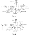
- FIG. 1 an illustrative view of an embodiment of a system in accordance with the disclosure is shown in Fig. 1 and is designated generally by reference character 100.
- FIG. 2 Other embodiments and/or aspects of this disclosure are shown in Fig. 2 .
- the systems and methods described herein can be used to shut off fuel flow rapidly (e.g., in the event of shaft shearing).
- a fuel system 100 for a turbomachine includes a minimum pressure and shutoff valve (MPSOV) 101 disposed between a fuel source (not shown) and a fuel nozzle (not shown) of the fuel system 100 and configured to move between an opened position wherein fuel can flow to the fuel nozzle (e.g., as shown in Fig. 1 ), and a closed position wherein fuel is prevented from flowing to the fuel nozzle (as shown in Fig. 2 ).
- MPSOV minimum pressure and shutoff valve
- the system 100 includes a shutdown signal valve (SDSV) 103 that is operatively connected to the MPSOV 101 and configured to selectively supply a shutdown pressure to the MPSOV 101 in a shutdown state such that the shutdown pressure forces the MPSOV 101 to the closed position (as shown in Fig. 2 ).
- SDSV shutdown signal valve
- the shutdown pressure can be supplied from a main pump flow. Any other suitable location for supplying the shutdown pressure is contemplated herein.
- the main pump flow is fine filtered first before being sent through to the SDSV 103.
- the SDSV 103 can be a pressure actuated valve and can include a signal port 105 for receiving a shutoff signal pressure.
- the SDSV 103 can be configured to move between a closed state (e.g., as shown in Fig. 1 ) to an opened state (as shown in Fig. 2 ) wherein the shutdown pressure can be supplied to the MPSOV 101, when the signal port 105 is exposed to the shutoff signal pressure.
- the shutoff signal pressure can be less than shutdown pressure such that a pressure greater or equal to shutdown pressure applied to the signal port 105 can maintain the SDSV 103 in the closed state.
- the signal port 105 can be operatively connected to an over-speed actuator 109 (e.g., a solenoid valve) such that shutdown pressure flows from the over-speed actuator 109 to the signal port 105 when over-speed is detected (e.g., after shaft shear).
- an over-speed actuator 109 e.g., a solenoid valve
- the SDSV 103 can be any other suitable valve type (e.g., an electromechanical valve) configured to operate in any suitable manner. It is also contemplated that a shaft shearing event may be directly or indirectly (e.g., via over speeding) sensed in any suitable manner, and SDSV 103 can be actuated (e.g., by a controller connected to a shaft shear/over speed sensor) in any suitable manner.
- a shaft shearing event may be directly or indirectly (e.g., via over speeding) sensed in any suitable manner, and SDSV 103 can be actuated (e.g., by a controller connected to a shaft shear/over speed sensor) in any suitable manner.
- the system 100 can further include a normal pressure line 107 configured to supply a normal pressure to the MPSOV 101 to urge the MPSOV 101 toward the closed position.
- the normal pressure is insufficient to close the MPSOV 101 in a normal operation and acts as a reference to which the MPSOV will set the minimum pressure.
- the normal pressure in the normal pressure line 107 can be a pump interstage pressure Pd (e.g., derived downstream of a pressure regulating valve 111 as shown).
- the MPSOV 101 can include a normal spring bias to urge the MPSOV 101 toward the closed position, the normal spring bias and/or the normal pressure being insufficient to close the MPSOV 101 in a normal operation.
- a method includes determining an over-speed condition of a turbomachine and supplying a shutdown pressure to a minimum pressure and shutoff valve (MPSOV) 101 from an shutdown signal valve (SDSV) 103.
- MPSOV minimum pressure and shutoff valve
- SDSV shutdown signal valve
- Embodiments of the method can be executed using any suitable hardware (e.g., a memory and processor) and/or software (e.g., associate with an engine controller, for example).
- shutdown can be controlled by the IFPC.
- the main turbomachine shaft can shear, causing rapid engine acceleration.
- One or more sensors can sense the rapid acceleration.
- an engine controller recognizes speed up and sends a shutdown signal to the IFPC.
- pressure would decay on the front side of the MPSOV 101 after opening a windmill bypass valve (WBV) 113 via an over-speed actuator (e.g., a solenoid), which slowly closes the MPSOV 101 due to a bias on the back side of the MPSOV 101.
- WBV windmill bypass valve
- an over-speed actuator e.g., a solenoid
- the IFPC can activate one or more over-speed actuators 109 (e.g., a solenoid) to operate the SDSV 103 (and along with the WBV 113 in certain embodiments to allow recirculation of excess flow) and decay engine speed and pressure.
- over-speed actuators 109 e.g., a solenoid
- the SDSV 103 injects a high pressure to the back side of the MPSOV 101 to rapidly close the MPSOV 101 regardless of the pressure still acting on the front side of the MPSOV 101.
- a quick shutdown of a turbine engine can be achieved (in either a normal or over-speed condition).
- Embodiments as described above can greatly decrease the shutoff time over traditional systems.
- utilizing a separate SDSV 103 valve allows the system to be lighter because of the minimal flow requirements for the valve.
- the separate valve can meet tighter leakage requirements.
Landscapes
- Engineering & Computer Science (AREA)
- Chemical & Material Sciences (AREA)
- Combustion & Propulsion (AREA)
- Mechanical Engineering (AREA)
- General Engineering & Computer Science (AREA)
- Control Of Turbines (AREA)
Abstract
Description
- The present disclosure relates to turbomachines, more specifically to fuel systems for turbomachines.
- In a turbine engine, a shaft shearing is a failure event that needs to be detected and responded to as quickly as possible. Over-speeding of the engine occurs due to instant reduction of resistance associated with shaft shearing. Once an over-speeding condition occurs, fuel flow to the turbine must be shut down as quickly as possible to prevent further damage to the engine and aircraft. It is an architectural challenge to meet the stringent shutdown requirements while trying to maintain lightweight and non-complex systems.
- Such conventional methods and systems have generally been considered satisfactory for their intended purpose. However, there is still a need in the art for improved fuel systems for turbomachines. The present disclosure provides a solution for this need.
- A fuel system for a turbomachine includes a minimum pressure and shutoff valve (MPSOV) disposed between a fuel source and a fuel nozzle of a fuel system and configured to move between an opened position wherein fuel can flow to the fuel nozzle, and a closed position wherein fuel is prevented from flowing to the fuel nozzle, a shutdown signal valve (SDSV) operatively connected to the MPSOV and configured to selectively supply a shutdown pressure to the MPSOV in a shutdown state such that the shutdown pressure forces the MPSOV to the closed position, and a bypass valve (WBV) connected to the MPSOV and SDSV such that when the MPSOV closes, the excess flow will be re-circulated to the pump inlet
- The shutdown pressure can be supplied from a main pump flow or any other suitable location. In certain embodiments, the main pump flow is fine filtered.
- The SDSV can be a pressure actuated valve and can include a signal port for receiving a shutoff signal pressure. The SDSV can be configured to move between a closed state to an opened state wherein the shutdown pressure can be supplied to the MPSOV when the signal port is exposed to the shutoff signal pressure.
- The shutoff signal pressure can be less than shutdown pressure such that a pressure greater or equal to shutdown pressure applied to the signal port can maintain the SDSV in the closed state. The signal port can be operatively connected to an over-speed actuator such that shutdown pressure flows from the over-speed actuator to the signal port when over-speed is detected.
- The system can further include a normal pressure line configured to supply a normal pressure to the MPSOV to urge the MPSOV toward the closed position, wherein the normal pressure is insufficient to close the MPSOV in a normal operation. The normal pressure can be a pump interstage pressure. In certain embodiments, the MPSOV can include a normal spring bias to urge the MPSOV toward the closed position, wherein the normal spring bias is insufficient to close the MPSOV in a normal operation.
- The WBV can allow excess flow to recirculate to the main pump after the MPSOV is shutoff by the SDSV. In certain embodiments, the WBV and SDSV are actuated by the same signal pressure to decrease operation time.
- In accordance with at least one aspect of this disclosure, a method includes determining an over-speed condition of a turbomachine and supplying a shutdown pressure to a minimum pressure and shutoff valve (MPSOV) from an shutdown signal valve (SDSV).
- These and other features of the systems and methods of the subject disclosure will become more readily apparent to those skilled in the art from the following detailed description taken in conjunction with the drawings.
- So that those skilled in the art to which the subject disclosure appertains will readily understand how to make and use the devices and methods of the subject disclosure without undue experimentation, embodiments thereof will be described in detail herein below with reference to certain figures, wherein:
-
Fig. 1 is a schematic flow diagram of an embodiment of a system in accordance with this disclosure, shown in a normal operating state; and -
Fig. 2 is a schematic flow diagram of the embodiment ofFig. 1 , shown in a shutdown state (e.g., due to over-speeding). - Reference will now be made to the drawings wherein like reference numerals identify similar structural features or aspects of the subject disclosure. For purposes of explanation and illustration, and not limitation, an illustrative view of an embodiment of a system in accordance with the disclosure is shown in
Fig. 1 and is designated generally by reference character 100. Other embodiments and/or aspects of this disclosure are shown inFig. 2 . The systems and methods described herein can be used to shut off fuel flow rapidly (e.g., in the event of shaft shearing). - Referring to
Figs. 1 and 2 , a fuel system 100 (e.g., and integrated fuel pump control (IFPC)) for a turbomachine includes a minimum pressure and shutoff valve (MPSOV) 101 disposed between a fuel source (not shown) and a fuel nozzle (not shown) of the fuel system 100 and configured to move between an opened position wherein fuel can flow to the fuel nozzle (e.g., as shown inFig. 1 ), and a closed position wherein fuel is prevented from flowing to the fuel nozzle (as shown inFig. 2 ). The system 100 includes a shutdown signal valve (SDSV) 103 that is operatively connected to the MPSOV 101 and configured to selectively supply a shutdown pressure to the MPSOV 101 in a shutdown state such that the shutdown pressure forces the MPSOV 101 to the closed position (as shown inFig. 2 ). - As shown, the shutdown pressure can be supplied from a main pump flow. Any other suitable location for supplying the shutdown pressure is contemplated herein. In certain embodiments, the main pump flow is fine filtered first before being sent through to the
SDSV 103. - In certain embodiments, as shown, the SDSV 103 can be a pressure actuated valve and can include a
signal port 105 for receiving a shutoff signal pressure. TheSDSV 103 can be configured to move between a closed state (e.g., as shown inFig. 1 ) to an opened state (as shown inFig. 2 ) wherein the shutdown pressure can be supplied to theMPSOV 101, when thesignal port 105 is exposed to the shutoff signal pressure. - The shutoff signal pressure can be less than shutdown pressure such that a pressure greater or equal to shutdown pressure applied to the
signal port 105 can maintain theSDSV 103 in the closed state. Thesignal port 105 can be operatively connected to an over-speed actuator 109 (e.g., a solenoid valve) such that shutdown pressure flows from the over-speedactuator 109 to thesignal port 105 when over-speed is detected (e.g., after shaft shear). - It is contemplated that the
SDSV 103 can be any other suitable valve type (e.g., an electromechanical valve) configured to operate in any suitable manner. It is also contemplated that a shaft shearing event may be directly or indirectly (e.g., via over speeding) sensed in any suitable manner, and SDSV 103 can be actuated (e.g., by a controller connected to a shaft shear/over speed sensor) in any suitable manner. - The system 100 can further include a
normal pressure line 107 configured to supply a normal pressure to the MPSOV 101 to urge the MPSOV 101 toward the closed position. However, the normal pressure is insufficient to close theMPSOV 101 in a normal operation and acts as a reference to which the MPSOV will set the minimum pressure. The normal pressure in thenormal pressure line 107 can be a pump interstage pressure Pd (e.g., derived downstream of apressure regulating valve 111 as shown). In certain embodiments, the MPSOV 101 can include a normal spring bias to urge the MPSOV 101 toward the closed position, the normal spring bias and/or the normal pressure being insufficient to close the MPSOV 101 in a normal operation. - In accordance with at least one aspect of this disclosure, a method includes determining an over-speed condition of a turbomachine and supplying a shutdown pressure to a minimum pressure and shutoff valve (MPSOV) 101 from an shutdown signal valve (SDSV) 103. Embodiments of the method can be executed using any suitable hardware (e.g., a memory and processor) and/or software (e.g., associate with an engine controller, for example).
- In turbomachines, shutdown can be controlled by the IFPC. In certain conditions, the main turbomachine shaft can shear, causing rapid engine acceleration. One or more sensors can sense the rapid acceleration. In such a case, an engine controller recognizes speed up and sends a shutdown signal to the IFPC. Traditionally, pressure would decay on the front side of the MPSOV 101 after opening a windmill bypass valve (WBV) 113 via an over-speed actuator (e.g., a solenoid), which slowly closes the MPSOV 101 due to a bias on the back side of the MPSOV 101. However, this is a relatively slow decay.
- As described herein, the IFPC can activate one or more over-speed actuators 109 (e.g., a solenoid) to operate the SDSV 103 (and along with the WBV 113 in certain embodiments to allow recirculation of excess flow) and decay engine speed and pressure. When operated, the SDSV 103 injects a high pressure to the back side of the MPSOV 101 to rapidly close the MPSOV 101 regardless of the pressure still acting on the front side of the MPSOV 101.
- By virtue of utilizing a very small and/or lightweight valve (the SDSV 103) to port high pressure flow to the back of the
MPSOV 101, a quick shutdown of a turbine engine can be achieved (in either a normal or over-speed condition). Embodiments as described above can greatly decrease the shutoff time over traditional systems. Also, utilizing aseparate SDSV 103 valve allows the system to be lighter because of the minimal flow requirements for the valve. In addition, the separate valve can meet tighter leakage requirements. - The methods and systems of the present disclosure, as described above and shown in the drawings, provide for fuel systems with superior properties including rapid shutoff. While the apparatus and methods of the subject disclosure have been shown and described with reference to embodiments, those skilled in the art will readily appreciate that changes and/or modifications may be made thereto without departing from the scope of the subject disclosure.
Claims (13)
- A fuel system (100) for a turbomachine, comprising:a minimum pressure and shutoff valve (MPSOV) (101) disposed between a fuel source and a fuel nozzle of the fuel system (100) and configured to move between an opened position wherein fuel can flow to the fuel nozzle, and a closed position wherein fuel is prevented from flowing to the fuel nozzle;a shutdown signal valve (SDSV) (103) operatively connected to the MPSOV (101) and configured to selectively supply a shutdown pressure to the MPSOV (101) in a shutdown state such that the shutdown pressure forces the MPSOV (101) to the closed position; anda bypass valve (WBV) (113) connected to the MPSOV (101) and SDSV (103) such that when the MPSOV (101) closes, the excess flow will be re-circulated to the pump inlet
- The system of claim 1, wherein the shutdown pressure is supplied from a main pump flow.
- The system of claim 2, wherein the main pump flow is fine filtered.
- The system of claim 1, wherein the SDSV (103) is a pressure actuated valve and includes a signal port (105) for receiving a shutoff signal pressure.
- The system of claim 4, wherein the SDSV (103) is configured to move between a closed state to an opened state wherein the shutdown pressure is supplied to the MPSOV (101), when the signal port (105) is exposed to the shutoff signal pressure.
- The system of claim 5, wherein the shutoff signal pressure is less than shutdown pressure such that a pressure greater or equal to shutdown pressure applied to the signal port (105) will maintain the SDSV (103) in the closed state.
- The system of claim 6, wherein the signal port (105) is operatively connected to an over-speed actuator such that shutdown pressure flows from the over-speed actuator to the signal port when over-speed is detected.
- The system of claim 1, further comprising a normal pressure line (107) configured to supply a normal pressure to the MPSOV (101) to urge the MPSOV (101) toward the closed position, wherein the normal pressure is insufficient to close the MPSOV (101) in a normal operation.
- The system of claim 8, wherein the normal pressure is a pump interstage pressure.
- The system of claim 9, wherein the MPSOV (101) further includes a normal spring bias to urge the MPSOV (101) toward the closed position, wherein the normal spring bias is insufficient to close the MPSOV (101) in a normal operation.
- The system of claim 2, wherein the WBV (113) allows the excess flow to recirculate to the main pump after the MPSOV (101) is shutoff by the SDSV (103).
- The system of claim 1, wherein the WBV (113) and SDSV (103) are actuated by the same signal pressure to decrease operation time.
- A method, comprising:determining an over-speed condition of a turbomachine; andsupplying a shutdown pressure to a minimum pressure and shutoff valve (MPSOV) from an shutdown signal valve (SDSV).
Applications Claiming Priority (1)
| Application Number | Priority Date | Filing Date | Title |
|---|---|---|---|
| US15/134,524 US20170306790A1 (en) | 2016-04-21 | 2016-04-21 | Fuel systems for turbomachines |
Publications (2)
| Publication Number | Publication Date |
|---|---|
| EP3236049A1 true EP3236049A1 (en) | 2017-10-25 |
| EP3236049B1 EP3236049B1 (en) | 2020-03-11 |
Family
ID=58464244
Family Applications (1)
| Application Number | Title | Priority Date | Filing Date |
|---|---|---|---|
| EP17163541.0A Active EP3236049B1 (en) | 2016-04-21 | 2017-03-29 | Fuel systems for turbomachines |
Country Status (2)
| Country | Link |
|---|---|
| US (1) | US20170306790A1 (en) |
| EP (1) | EP3236049B1 (en) |
Families Citing this family (4)
| Publication number | Priority date | Publication date | Assignee | Title |
|---|---|---|---|---|
| FR3096412B1 (en) * | 2019-05-24 | 2022-07-22 | Safran Aircraft Engines | FUEL SUPPLY SYSTEM OF A TURBOMACHINE WITH FUEL FLOW REGULATION |
| US11828233B2 (en) * | 2021-11-26 | 2023-11-28 | Hamilton Sundstrand Corporation | Fuel pump systems |
| US11808218B1 (en) * | 2022-04-27 | 2023-11-07 | Hamilton Sundstrand Corporation | Rapid fuel shutdown system with latching |
| US20250027491A1 (en) * | 2023-07-21 | 2025-01-23 | Hamilton Sundstrand Corporation | Combined high pressure relief and bypass valves |
Citations (3)
| Publication number | Priority date | Publication date | Assignee | Title |
|---|---|---|---|---|
| US4602479A (en) * | 1985-06-12 | 1986-07-29 | United Technologies Corporation | Fuel control |
| EP1295021A1 (en) * | 2000-06-23 | 2003-03-26 | Hamilton Sundstrand Corporation | Method and apparatus for providing shutoff, overspeed protection, and directional control of a bypass flow in a fuel delivery system |
| US20120042657A1 (en) * | 2009-04-29 | 2012-02-23 | Snecma | method and device for feeding a turbomachine combustion chamber with a regulated flow of fuel |
Family Cites Families (3)
| Publication number | Priority date | Publication date | Assignee | Title |
|---|---|---|---|---|
| FR2984958B1 (en) * | 2011-12-21 | 2014-01-17 | Ge Energy Products France Snc | EVENT FOR GAS FUEL SUPPLY CIRCUIT OF GAS TURBINE, AND ASSOCIATED METHOD |
| GB201301791D0 (en) * | 2013-02-01 | 2013-03-20 | Rolls Royce Engine Control Systems Ltd | Engine fuel control system |
| EP2986831A2 (en) * | 2013-04-14 | 2016-02-24 | General Electric Company | Engine overspeed protection with thrust control |
-
2016
- 2016-04-21 US US15/134,524 patent/US20170306790A1/en not_active Abandoned
-
2017
- 2017-03-29 EP EP17163541.0A patent/EP3236049B1/en active Active
Patent Citations (3)
| Publication number | Priority date | Publication date | Assignee | Title |
|---|---|---|---|---|
| US4602479A (en) * | 1985-06-12 | 1986-07-29 | United Technologies Corporation | Fuel control |
| EP1295021A1 (en) * | 2000-06-23 | 2003-03-26 | Hamilton Sundstrand Corporation | Method and apparatus for providing shutoff, overspeed protection, and directional control of a bypass flow in a fuel delivery system |
| US20120042657A1 (en) * | 2009-04-29 | 2012-02-23 | Snecma | method and device for feeding a turbomachine combustion chamber with a regulated flow of fuel |
Also Published As
| Publication number | Publication date |
|---|---|
| US20170306790A1 (en) | 2017-10-26 |
| EP3236049B1 (en) | 2020-03-11 |
Similar Documents
| Publication | Publication Date | Title |
|---|---|---|
| US10502138B2 (en) | Dual pump fuel system with pump sharing connection | |
| EP3236049B1 (en) | Fuel systems for turbomachines | |
| EP2171216B1 (en) | Closed-loop control for a gas turbine with actively stabilized compressor | |
| EP3081784B1 (en) | Gas turbine fuel control system with shutoff feature and associated method | |
| EP1944485A2 (en) | Fuel system for a gas turbine engine and operation method therefore | |
| JP4150961B2 (en) | Method and apparatus for preventing rotor overspeed and overboost | |
| EP2796688B1 (en) | System for controlling two positive displacement pumps | |
| US9470152B2 (en) | Engine fuel control system | |
| US8843253B1 (en) | Aircraft ice protection control system and method for mitigating engine over-bleed | |
| US8720482B2 (en) | Fuel system | |
| EP3067537A1 (en) | Overthrust protection system and method | |
| JPH04259630A (en) | Fuel control device for gas turbine engine | |
| JP6027193B2 (en) | Geared turbofan engine with low pressure environmental control system for aircraft | |
| DE112016004296T5 (en) | GUESTURBINE CONTROL DEVICE AND METHOD, GAS TURBINE CONTROL PROGRAM AND GAS TURBINE | |
| JP4702385B2 (en) | Fan control device | |
| US9267477B2 (en) | Variable minimum pressure system | |
| EP3744958B1 (en) | Fuel system with integrated thrust control malfunction protection and method | |
| EP3098510B1 (en) | Gas turbine engine uncontrolled high thrust accommodation system and method | |
| CN105408587A (en) | Valve for a turbomachine | |
| EP3171005B1 (en) | Fuel supply system for use in a gas turbine engine and method of controlling an overspeed event therein | |
| US20220082027A1 (en) | Method for monitoring the operating state of a system for positioning variable-geometry members of a turbomachine | |
| US20240240631A1 (en) | Direct control for variable displacement pumps | |
| CN113710887B (en) | Turbine fuel supply system for regulating fuel flow | |
| EP4722517A2 (en) | Variable displacement pump metering control with upstream fuel shut-off | |
| US12140090B2 (en) | Gas turbine engine control system and method for limiting turbine overspeed in case of a shaft failure |
Legal Events
| Date | Code | Title | Description |
|---|---|---|---|
| PUAI | Public reference made under article 153(3) epc to a published international application that has entered the european phase |
Free format text: ORIGINAL CODE: 0009012 |
|
| STAA | Information on the status of an ep patent application or granted ep patent |
Free format text: STATUS: THE APPLICATION HAS BEEN PUBLISHED |
|
| AK | Designated contracting states |
Kind code of ref document: A1 Designated state(s): AL AT BE BG CH CY CZ DE DK EE ES FI FR GB GR HR HU IE IS IT LI LT LU LV MC MK MT NL NO PL PT RO RS SE SI SK SM TR |
|
| AX | Request for extension of the european patent |
Extension state: BA ME |
|
| RIN1 | Information on inventor provided before grant (corrected) |
Inventor name: CORETTO, AUGUST M. Inventor name: RICKIS, AARON |
|
| STAA | Information on the status of an ep patent application or granted ep patent |
Free format text: STATUS: REQUEST FOR EXAMINATION WAS MADE |
|
| 17P | Request for examination filed |
Effective date: 20180425 |
|
| RBV | Designated contracting states (corrected) |
Designated state(s): AL AT BE BG CH CY CZ DE DK EE ES FI FR GB GR HR HU IE IS IT LI LT LU LV MC MK MT NL NO PL PT RO RS SE SI SK SM TR |
|
| STAA | Information on the status of an ep patent application or granted ep patent |
Free format text: STATUS: EXAMINATION IS IN PROGRESS |
|
| 17Q | First examination report despatched |
Effective date: 20181019 |
|
| GRAP | Despatch of communication of intention to grant a patent |
Free format text: ORIGINAL CODE: EPIDOSNIGR1 |
|
| STAA | Information on the status of an ep patent application or granted ep patent |
Free format text: STATUS: GRANT OF PATENT IS INTENDED |
|
| INTG | Intention to grant announced |
Effective date: 20190925 |
|
| GRAS | Grant fee paid |
Free format text: ORIGINAL CODE: EPIDOSNIGR3 |
|
| GRAA | (expected) grant |
Free format text: ORIGINAL CODE: 0009210 |
|
| STAA | Information on the status of an ep patent application or granted ep patent |
Free format text: STATUS: THE PATENT HAS BEEN GRANTED |
|
| AK | Designated contracting states |
Kind code of ref document: B1 Designated state(s): AL AT BE BG CH CY CZ DE DK EE ES FI FR GB GR HR HU IE IS IT LI LT LU LV MC MK MT NL NO PL PT RO RS SE SI SK SM TR |
|
| REG | Reference to a national code |
Ref country code: GB Ref legal event code: FG4D |
|
| REG | Reference to a national code |
Ref country code: CH Ref legal event code: EP |
|
| REG | Reference to a national code |
Ref country code: AT Ref legal event code: REF Ref document number: 1243407 Country of ref document: AT Kind code of ref document: T Effective date: 20200315 |
|
| REG | Reference to a national code |
Ref country code: IE Ref legal event code: FG4D |
|
| REG | Reference to a national code |
Ref country code: DE Ref legal event code: R096 Ref document number: 602017012774 Country of ref document: DE |
|
| PG25 | Lapsed in a contracting state [announced via postgrant information from national office to epo] |
Ref country code: NO Free format text: LAPSE BECAUSE OF FAILURE TO SUBMIT A TRANSLATION OF THE DESCRIPTION OR TO PAY THE FEE WITHIN THE PRESCRIBED TIME-LIMIT Effective date: 20200611 Ref country code: FI Free format text: LAPSE BECAUSE OF FAILURE TO SUBMIT A TRANSLATION OF THE DESCRIPTION OR TO PAY THE FEE WITHIN THE PRESCRIBED TIME-LIMIT Effective date: 20200311 Ref country code: RS Free format text: LAPSE BECAUSE OF FAILURE TO SUBMIT A TRANSLATION OF THE DESCRIPTION OR TO PAY THE FEE WITHIN THE PRESCRIBED TIME-LIMIT Effective date: 20200311 |
|
| REG | Reference to a national code |
Ref country code: NL Ref legal event code: MP Effective date: 20200311 |
|
| PG25 | Lapsed in a contracting state [announced via postgrant information from national office to epo] |
Ref country code: HR Free format text: LAPSE BECAUSE OF FAILURE TO SUBMIT A TRANSLATION OF THE DESCRIPTION OR TO PAY THE FEE WITHIN THE PRESCRIBED TIME-LIMIT Effective date: 20200311 Ref country code: BG Free format text: LAPSE BECAUSE OF FAILURE TO SUBMIT A TRANSLATION OF THE DESCRIPTION OR TO PAY THE FEE WITHIN THE PRESCRIBED TIME-LIMIT Effective date: 20200611 Ref country code: LV Free format text: LAPSE BECAUSE OF FAILURE TO SUBMIT A TRANSLATION OF THE DESCRIPTION OR TO PAY THE FEE WITHIN THE PRESCRIBED TIME-LIMIT Effective date: 20200311 Ref country code: SE Free format text: LAPSE BECAUSE OF FAILURE TO SUBMIT A TRANSLATION OF THE DESCRIPTION OR TO PAY THE FEE WITHIN THE PRESCRIBED TIME-LIMIT Effective date: 20200311 Ref country code: GR Free format text: LAPSE BECAUSE OF FAILURE TO SUBMIT A TRANSLATION OF THE DESCRIPTION OR TO PAY THE FEE WITHIN THE PRESCRIBED TIME-LIMIT Effective date: 20200612 |
|
| REG | Reference to a national code |
Ref country code: LT Ref legal event code: MG4D |
|
| PG25 | Lapsed in a contracting state [announced via postgrant information from national office to epo] |
Ref country code: NL Free format text: LAPSE BECAUSE OF FAILURE TO SUBMIT A TRANSLATION OF THE DESCRIPTION OR TO PAY THE FEE WITHIN THE PRESCRIBED TIME-LIMIT Effective date: 20200311 |
|
| PG25 | Lapsed in a contracting state [announced via postgrant information from national office to epo] |
Ref country code: LT Free format text: LAPSE BECAUSE OF FAILURE TO SUBMIT A TRANSLATION OF THE DESCRIPTION OR TO PAY THE FEE WITHIN THE PRESCRIBED TIME-LIMIT Effective date: 20200311 Ref country code: SM Free format text: LAPSE BECAUSE OF FAILURE TO SUBMIT A TRANSLATION OF THE DESCRIPTION OR TO PAY THE FEE WITHIN THE PRESCRIBED TIME-LIMIT Effective date: 20200311 Ref country code: EE Free format text: LAPSE BECAUSE OF FAILURE TO SUBMIT A TRANSLATION OF THE DESCRIPTION OR TO PAY THE FEE WITHIN THE PRESCRIBED TIME-LIMIT Effective date: 20200311 Ref country code: CZ Free format text: LAPSE BECAUSE OF FAILURE TO SUBMIT A TRANSLATION OF THE DESCRIPTION OR TO PAY THE FEE WITHIN THE PRESCRIBED TIME-LIMIT Effective date: 20200311 Ref country code: IS Free format text: LAPSE BECAUSE OF FAILURE TO SUBMIT A TRANSLATION OF THE DESCRIPTION OR TO PAY THE FEE WITHIN THE PRESCRIBED TIME-LIMIT Effective date: 20200711 Ref country code: RO Free format text: LAPSE BECAUSE OF FAILURE TO SUBMIT A TRANSLATION OF THE DESCRIPTION OR TO PAY THE FEE WITHIN THE PRESCRIBED TIME-LIMIT Effective date: 20200311 Ref country code: SK Free format text: LAPSE BECAUSE OF FAILURE TO SUBMIT A TRANSLATION OF THE DESCRIPTION OR TO PAY THE FEE WITHIN THE PRESCRIBED TIME-LIMIT Effective date: 20200311 Ref country code: PT Free format text: LAPSE BECAUSE OF FAILURE TO SUBMIT A TRANSLATION OF THE DESCRIPTION OR TO PAY THE FEE WITHIN THE PRESCRIBED TIME-LIMIT Effective date: 20200805 |
|
| REG | Reference to a national code |
Ref country code: CH Ref legal event code: PL |
|
| REG | Reference to a national code |
Ref country code: AT Ref legal event code: MK05 Ref document number: 1243407 Country of ref document: AT Kind code of ref document: T Effective date: 20200311 |
|
| REG | Reference to a national code |
Ref country code: DE Ref legal event code: R097 Ref document number: 602017012774 Country of ref document: DE |
|
| REG | Reference to a national code |
Ref country code: BE Ref legal event code: MM Effective date: 20200331 |
|
| PG25 | Lapsed in a contracting state [announced via postgrant information from national office to epo] |
Ref country code: LU Free format text: LAPSE BECAUSE OF NON-PAYMENT OF DUE FEES Effective date: 20200329 Ref country code: MC Free format text: LAPSE BECAUSE OF FAILURE TO SUBMIT A TRANSLATION OF THE DESCRIPTION OR TO PAY THE FEE WITHIN THE PRESCRIBED TIME-LIMIT Effective date: 20200311 |
|
| PLBE | No opposition filed within time limit |
Free format text: ORIGINAL CODE: 0009261 |
|
| STAA | Information on the status of an ep patent application or granted ep patent |
Free format text: STATUS: NO OPPOSITION FILED WITHIN TIME LIMIT |
|
| PG25 | Lapsed in a contracting state [announced via postgrant information from national office to epo] |
Ref country code: CH Free format text: LAPSE BECAUSE OF NON-PAYMENT OF DUE FEES Effective date: 20200331 Ref country code: IE Free format text: LAPSE BECAUSE OF NON-PAYMENT OF DUE FEES Effective date: 20200329 Ref country code: AT Free format text: LAPSE BECAUSE OF FAILURE TO SUBMIT A TRANSLATION OF THE DESCRIPTION OR TO PAY THE FEE WITHIN THE PRESCRIBED TIME-LIMIT Effective date: 20200311 Ref country code: DK Free format text: LAPSE BECAUSE OF FAILURE TO SUBMIT A TRANSLATION OF THE DESCRIPTION OR TO PAY THE FEE WITHIN THE PRESCRIBED TIME-LIMIT Effective date: 20200311 Ref country code: IT Free format text: LAPSE BECAUSE OF FAILURE TO SUBMIT A TRANSLATION OF THE DESCRIPTION OR TO PAY THE FEE WITHIN THE PRESCRIBED TIME-LIMIT Effective date: 20200311 Ref country code: LI Free format text: LAPSE BECAUSE OF NON-PAYMENT OF DUE FEES Effective date: 20200331 Ref country code: ES Free format text: LAPSE BECAUSE OF FAILURE TO SUBMIT A TRANSLATION OF THE DESCRIPTION OR TO PAY THE FEE WITHIN THE PRESCRIBED TIME-LIMIT Effective date: 20200311 |
|
| 26N | No opposition filed |
Effective date: 20201214 |
|
| PG25 | Lapsed in a contracting state [announced via postgrant information from national office to epo] |
Ref country code: SI Free format text: LAPSE BECAUSE OF FAILURE TO SUBMIT A TRANSLATION OF THE DESCRIPTION OR TO PAY THE FEE WITHIN THE PRESCRIBED TIME-LIMIT Effective date: 20200311 Ref country code: BE Free format text: LAPSE BECAUSE OF NON-PAYMENT OF DUE FEES Effective date: 20200331 Ref country code: PL Free format text: LAPSE BECAUSE OF FAILURE TO SUBMIT A TRANSLATION OF THE DESCRIPTION OR TO PAY THE FEE WITHIN THE PRESCRIBED TIME-LIMIT Effective date: 20200311 |
|
| PG25 | Lapsed in a contracting state [announced via postgrant information from national office to epo] |
Ref country code: TR Free format text: LAPSE BECAUSE OF FAILURE TO SUBMIT A TRANSLATION OF THE DESCRIPTION OR TO PAY THE FEE WITHIN THE PRESCRIBED TIME-LIMIT Effective date: 20200311 Ref country code: MT Free format text: LAPSE BECAUSE OF FAILURE TO SUBMIT A TRANSLATION OF THE DESCRIPTION OR TO PAY THE FEE WITHIN THE PRESCRIBED TIME-LIMIT Effective date: 20200311 Ref country code: CY Free format text: LAPSE BECAUSE OF FAILURE TO SUBMIT A TRANSLATION OF THE DESCRIPTION OR TO PAY THE FEE WITHIN THE PRESCRIBED TIME-LIMIT Effective date: 20200311 |
|
| PG25 | Lapsed in a contracting state [announced via postgrant information from national office to epo] |
Ref country code: MK Free format text: LAPSE BECAUSE OF FAILURE TO SUBMIT A TRANSLATION OF THE DESCRIPTION OR TO PAY THE FEE WITHIN THE PRESCRIBED TIME-LIMIT Effective date: 20200311 Ref country code: AL Free format text: LAPSE BECAUSE OF FAILURE TO SUBMIT A TRANSLATION OF THE DESCRIPTION OR TO PAY THE FEE WITHIN THE PRESCRIBED TIME-LIMIT Effective date: 20200311 |
|
| P01 | Opt-out of the competence of the unified patent court (upc) registered |
Effective date: 20230522 |
|
| PGFP | Annual fee paid to national office [announced via postgrant information from national office to epo] |
Ref country code: GB Payment date: 20260219 Year of fee payment: 10 |
|
| PGFP | Annual fee paid to national office [announced via postgrant information from national office to epo] |
Ref country code: DE Payment date: 20260219 Year of fee payment: 10 |
|
| PGFP | Annual fee paid to national office [announced via postgrant information from national office to epo] |
Ref country code: FR Payment date: 20260219 Year of fee payment: 10 |