EP3236043A1 - Engine system - Google Patents
Engine system Download PDFInfo
- Publication number
- EP3236043A1 EP3236043A1 EP16735114.7A EP16735114A EP3236043A1 EP 3236043 A1 EP3236043 A1 EP 3236043A1 EP 16735114 A EP16735114 A EP 16735114A EP 3236043 A1 EP3236043 A1 EP 3236043A1
- Authority
- EP
- European Patent Office
- Prior art keywords
- pressure stage
- low
- compressor
- supercharger
- stage compressor
- Prior art date
- Legal status (The legal status is an assumption and is not a legal conclusion. Google has not performed a legal analysis and makes no representation as to the accuracy of the status listed.)
- Granted
Links
Images


Classifications
-
- F—MECHANICAL ENGINEERING; LIGHTING; HEATING; WEAPONS; BLASTING
- F02—COMBUSTION ENGINES; HOT-GAS OR COMBUSTION-PRODUCT ENGINE PLANTS
- F02B—INTERNAL-COMBUSTION PISTON ENGINES; COMBUSTION ENGINES IN GENERAL
- F02B37/00—Engines characterised by provision of pumps driven at least for part of the time by exhaust
- F02B37/013—Engines characterised by provision of pumps driven at least for part of the time by exhaust with exhaust-driven pumps arranged in series
-
- F—MECHANICAL ENGINEERING; LIGHTING; HEATING; WEAPONS; BLASTING
- F02—COMBUSTION ENGINES; HOT-GAS OR COMBUSTION-PRODUCT ENGINE PLANTS
- F02B—INTERNAL-COMBUSTION PISTON ENGINES; COMBUSTION ENGINES IN GENERAL
- F02B37/00—Engines characterised by provision of pumps driven at least for part of the time by exhaust
- F02B37/001—Engines characterised by provision of pumps driven at least for part of the time by exhaust using exhaust drives arranged in parallel
-
- F—MECHANICAL ENGINEERING; LIGHTING; HEATING; WEAPONS; BLASTING
- F02—COMBUSTION ENGINES; HOT-GAS OR COMBUSTION-PRODUCT ENGINE PLANTS
- F02B—INTERNAL-COMBUSTION PISTON ENGINES; COMBUSTION ENGINES IN GENERAL
- F02B37/00—Engines characterised by provision of pumps driven at least for part of the time by exhaust
- F02B37/004—Engines characterised by provision of pumps driven at least for part of the time by exhaust with exhaust drives arranged in series
-
- F—MECHANICAL ENGINEERING; LIGHTING; HEATING; WEAPONS; BLASTING
- F02—COMBUSTION ENGINES; HOT-GAS OR COMBUSTION-PRODUCT ENGINE PLANTS
- F02B—INTERNAL-COMBUSTION PISTON ENGINES; COMBUSTION ENGINES IN GENERAL
- F02B37/00—Engines characterised by provision of pumps driven at least for part of the time by exhaust
- F02B37/007—Engines characterised by provision of pumps driven at least for part of the time by exhaust with exhaust-driven pumps arranged in parallel, e.g. at least one pump supplying alternatively
-
- Y—GENERAL TAGGING OF NEW TECHNOLOGICAL DEVELOPMENTS; GENERAL TAGGING OF CROSS-SECTIONAL TECHNOLOGIES SPANNING OVER SEVERAL SECTIONS OF THE IPC; TECHNICAL SUBJECTS COVERED BY FORMER USPC CROSS-REFERENCE ART COLLECTIONS [XRACs] AND DIGESTS
- Y02—TECHNOLOGIES OR APPLICATIONS FOR MITIGATION OR ADAPTATION AGAINST CLIMATE CHANGE
- Y02T—CLIMATE CHANGE MITIGATION TECHNOLOGIES RELATED TO TRANSPORTATION
- Y02T10/00—Road transport of goods or passengers
- Y02T10/10—Internal combustion engine [ICE] based vehicles
- Y02T10/12—Improving ICE efficiencies
Definitions
- the present invention relates to an engine system including a plurality of cylinder groups and a supercharger which compresses a gas supplied to the cylinder groups.
- Patent Literature 1 Japanese Patent No. 4295904
- the engine described in Patent Document 1 is a V-type engine having two cylinder groups (banks).
- the exhaust gas discharged from each cylinder group is connected to different superchargers.
- the turbine outputs differ respectively. Therefore, a task of compressing the gas mixture with a compressor of the superchargers is also different.
- the supercharger operates off a planned operating point.
- the efficiency may be degraded or there may be operation beyond a surge line of the supercharger.
- the present invention provides an engine system capable of making the air-intake flow rate and the pressure ratio between cylinder groups close to being equal to each other even when exhaust energies of the exhaust gases discharged from a plurality of cylinder groups are different from each other.
- an engine system includes a plurality of cylinder groups which burn a supplied gas mixture and discharge an exhaust gas, a plurality of high-pressure stage superchargers each having a high-pressure stage turbine driven by the exhaust gas of the corresponding cylinder group and a high-pressure stage compressor rotated by driving of the high-pressure stage turbine and configured to compress a gas supplied to the corresponding cylinder group, and a plurality of low-pressure stage superchargers each having a low-pressure stage turbine driven by an exhaust gas discharged from the high-pressure stage turbine of any one high-pressure stage supercharger of the plurality of high-pressure stage superchargers and a low-pressure stage compressor rotated by driving of the low-pressure stage turbine and configured to compress a gas supplied to a high-pressure stage compressor of a high-pressure stage supercharger other than the one high-pressure stage supercharger.
- an engine system includes a first cylinder group and a second cylinder group which burn a supplied gas mixture and discharge an exhaust gas, a first high-pressure stage supercharger and a second high-pressure stage supercharger each having a high-pressure stage turbine driven by the exhaust gas of the corresponding cylinder group and a high-pressure stage compressor rotated by driving of the high-pressure stage turbine and configured to compress a gas supplied to the corresponding cylinder group, a first low-pressure stage supercharger having a first low-pressure stage turbine driven by an exhaust gas discharged from the high-pressure stage turbine of the first high-pressure stage supercharger and a first low-pressure stage compressor rotated by driving of the first low-pressure stage turbine and configured to compress a gas supplied to the high-pressure stage compressor of the second high-pressure stage supercharger, and a second low-pressure stage supercharger having a second low-pressure stage turbine driven by an exhaust gas discharged from the high-pressure stage turbine of the second high-pressure stage supercharger and a
- a pipe connecting the low-pressure stage compressor to the high-pressure stage compressor may be formed so that the gas introduced into the high-pressure stage compressor swirls in a rotational direction of the high-pressure stage compressor.
- the engine system 1 of the present embodiment is a system including a two-stage (a multistage) supercharging system in which an engine main body 2 having two cylinder groups 10 and 20 including a first cylinder group 10 (a right bank) and a second cylinder group 20 (a left bank), two high-pressure stage superchargers 11 and 21 including a first high-pressure stage supercharger 11 and a second high-pressure stage supercharger 21, and two low-pressure stage superchargers 12 and 22 including a first low-pressure stage supercharger 12 and a second low-pressure stage supercharger 22 are provided. That is, the engine system 1 of the present embodiment includes four superchargers 11, 12, 21, and 22. A pressure of introduced air A is increased by the low-pressure stage superchargers 12 and 22 and the high-pressure stage superchargers 11 and 21.
- the engine main body 2 can employ an engine that acquires a driving force by burning a gas mixture of a main fuel gas (a fuel gas) such as natural gas, city gas, or the like and air A, for example.
- a main fuel gas a fuel gas
- the engine main body 2 is, for example, a V-type twelve-cylinder engine having twelve cylinders in total configured with the cylinder groups 10 and 20 each having 6 cylinders.
- the first high-pressure stage supercharger 11 has a first high-pressure stage turbine 13 and a first high-pressure stage compressor 14 uniaxially connected to the first high-pressure stage turbine 13. That is, the first high-pressure stage compressor 14 and the first high-pressure stage turbine 13 are connected by a shaft member, and the first high-pressure stage compressor 14 is rotated by the driving of the first high-pressure stage turbine 13.
- the second high-pressure stage supercharger 21 has a second high-pressure stage turbine 23 and a second high-pressure stage compressor 24 uniaxially connected to the second high-pressure stage turbine 23.
- the first low-pressure stage supercharger 12 has a first low-pressure stage turbine 15 and a first low-pressure stage compressor 16 uniaxially connected to the first low-pressure stage turbine 15.
- the second low-pressure stage supercharger 22 has a second low-pressure stage turbine 25 and a second low-pressure stage compressor 26 uniaxially connected to the second low-pressure stage turbine 25.
- a first high-pressure stage exhaust pipe 17 serving as a pipe into which an exhaust gas E of the first cylinder group 10 is introduced is connected to the first high-pressure stage turbine 13 of the first high-pressure stage supercharger 11.
- the first high-pressure stage turbine 13 and the first low-pressure stage turbine 15 are connected by a first low-pressure stage exhaust pipe 18. That is, the first high-pressure stage turbine 13 and the first low-pressure stage turbine 15 are rotated by exhaust energies of the exhaust gases E discharged from the first cylinder group 10, and thus the first high-pressure stage compressor 14 connected to the first high-pressure stage turbine 13 and the first low-pressure stage compressor 16 connected to the first low-pressure stage turbine 15 rotate.
- a second high-pressure stage exhaust pipe 27 serving as a pipe into which an exhaust gas E of the second cylinder group 20 is introduced is connected to the second high-pressure stage turbine 23 of the second high-pressure stage supercharger 21.
- the second high-pressure stage turbine 23 and the second low-pressure stage turbine 25 are connected by a second low-pressure stage exhaust pipe 28. That is, the second high-pressure stage turbine 23 and the second low-pressure stage turbine 25 are rotated by exhaust energy of the exhaust gas E discharged from the second cylinder group 20, and thus the second high-pressure stage compressor 24 and the second low-pressure stage compressor 26 rotate.
- An air discharge port of the first low-pressure stage compressor 16 of the first low-pressure stage supercharger 12 is connected to an air inlet port of the second high-pressure stage compressor 24 of the second high-pressure stage supercharger 21 via a first crossing pipe 3.
- the compressed air A discharged from the first low-pressure stage compressor 16 is not introduced into the first high-pressure stage compressor 14 but is introduced into the second high-pressure stage compressor 24 via the first crossing pipe 3.
- the compressed air A compressed by the first low-pressure stage compressor 16 of the right bank (the first cylinder group 10) is compressed by the second high-pressure stage compressor 24 of the left bank (the second cylinder group 20) on a side opposite thereto.
- the compressed air A discharged from the second high-pressure stage compressor 24 is supplied to the second cylinder group 20 via a second high-pressure stage air pipe 29.
- An air discharge port of the second low-pressure stage compressor 26 of the second low-pressure stage supercharger 22 is connected to an air inlet port of the first high-pressure stage compressor 14 of the first high-pressure stage supercharger 11 via a second crossing pipe 4. That is, the compressed air A discharged from the second low-pressure stage compressor 26 is introduced into the first high-pressure stage compressor 14 and is then supplied to the first cylinder group 10 via a first high-pressure stage air pipe 19.
- the engine system 1 of the present embodiment includes a plurality of low-pressure stage superchargers 12 and 22 each having the low-pressure stage turbine 15 driven by the exhaust gas E discharged from the high-pressure stage turbine 13 of the high-pressure stage supercharger 11 which is any one of the plurality of high-pressure stage superchargers 11 and 21, and the low-pressure stage compressor 16 rotated by the driving of the low-pressure stage turbine 15 and configured to compress the compressed air A supplied to the high-pressure stage compressor 24 of a high-pressure stage supercharger 21 other than the one high-pressure stage supercharger 11.
- the first crossing pipe 3 and the second crossing pipe 4 When the first crossing pipe 3 and the second crossing pipe 4 are disposed as described above, the first crossing pipe 3 and the second crossing pipe 4 require bent portions. As illustrated in Fig. 2 , for example, the first crossing pipe 3 includes a plurality of bent portions 5.
- a connecting portion 6 of the first crossing pipe 3 with respect to the second high-pressure stage compressor 24 is formed such that the compressed air A introduced into the second high-pressure stage compressor 24 swirls in a rotational direction R of an impeller of the second high-pressure stage compressor 24.
- the first crossing pipe 3 is formed so that an axial direction of the pipe in the connecting portion 6 is curved to follow the flow of the compressed air A flowing in the second high-pressure stage compressor 24. Thereby, a force is imparted to the compressed air A flowing in the first crossing pipe 3 such that a swirling motion is performed in a forward direction with respect to the rotational direction R of an impeller constituting the first high-pressure stage compressor 14.
- a connecting portion of the second crossing pipe 4 with respect to the first high-pressure stage compressor 14 is formed such that the compressed air A introduced into the first high-pressure stage compressor 14 swirls in a rotational direction of an impeller of the first high-pressure stage compressor 14.
- a pressure ratio (a compression ratio) between the first high-pressure stage compressor 14 and the first low-pressure stage compressor 16 and a pressure ratio between the second high-pressure stage compressor 24 and the second low-pressure stage compressor 26 are substantially the same, and then pressures at an outlet of the first high-pressure stage compressor and an outlet of the second high-pressure stage compressor 24 are substantially the same. That is, the pressures of the compressed air A supplied to the first cylinder group 10 and the second cylinder group 20 of the engine main body 2 are increased to the same extent.
- the exhaust gas E discharged from the first cylinder group 10 reaches a high temperature and high flow rate and outputs of the first high-pressure stage turbine 13 and the first low-pressure stage turbine 15 continue to increase while the exhaust gas E discharged from the second cylinder group 20 becomes a low temperature and low flow rate and outputs of the second high-pressure stage turbine 23 and the second low-pressure stage turbine 25 decrease.
- a supercharging efficiency map (a map illustrating how much rotational energy of the turbine can be converted to a pressure increase by the compressor) for the efficiency reduction in such a case.
- Fig. 4 is a view illustrating a supercharging efficiency map of a high-pressure stage supercharger.
- the horizontal axis in Fig. 4 is an air flow rate.
- the vertical axis in Fig. 4 is a pressure ratio, that is, a ratio of the air pressure immediately after flowing out from a compressor to the air pressure immediately before flowing into the compressor.
- a plurality of annular lines are efficiencies obtained from the correlation between the air flow rate and the pressure ratio, and the efficiency becomes higher as the line is closer to the center.
- Line S is a surge line and line C is a choke line.
- a region T surrounded by the surge line S and the choke line C is the operation region of the compressor.
- a center point P of the plurality of annular lines is the most efficient operating point.
- a large difference may occur in compression ratio of the compressed air A supplied to a first cylinder group 10 and a second cylinder group 20.
- the operating point of the second low-pressure stage compressor 26 moves to the P2 side. That is, it operates off the most efficient operating point.
- the compressed air A discharged from the first low-pressure stage compressor 16 is introduced into the second high-pressure stage compressor 24 via the first crossing pipe 3.
- the compressed air A discharged from the second low-pressure stage compressor 26 is introduced into the first high-pressure stage compressor 14 via the second crossing pipe 4.
- the compressed air compressed by the first low-pressure stage compressor 16 of the right bank is compressed by the second high-pressure stage compressor 24 of the left bank and supplied to the engine.
- the compressed air A compressed by the second low-pressure stage compressor 26 of the left bank is compressed by the first high-pressure stage compressor 14 of the right bank and supplied to the engine.
- the compressed air A compressed by the first low-pressure stage compressor 16 having a high output is supplied to the second high-pressure stage compressor 24 having a low output.
- the compressed air A compressed by the second low-pressure stage compressor 26 having a low output is supplied to the first high-pressure stage compressor 14 having a high output.
- the connecting portions of the crossing pipes 3 and 4 with respect to the high-pressure stage compressor 14 and 24 are formed such that the compressed air A introduced into the high-pressure stage compressor 14 and 24 swirls in the rotational direction R of the high-pressure stage compressor 14 and 24.
- the number of cylinder groups is not limited to two, and the engine system 1 may have a configuration in which three or more cylinder groups are provided, for example.
Landscapes
- Engineering & Computer Science (AREA)
- Chemical & Material Sciences (AREA)
- Combustion & Propulsion (AREA)
- Mechanical Engineering (AREA)
- General Engineering & Computer Science (AREA)
- Supercharger (AREA)
Abstract
Description
- The present invention relates to an engine system including a plurality of cylinder groups and a supercharger which compresses a gas supplied to the cylinder groups.
- Priority is claimed on Japanese Patent Application No.
2015-003072, filed January 9, 2015 - Conventionally, in an internal combustion engine such as a gas engine including a large number of cylinders, for the purpose of achieving high output and low fuel consumption, one having a plurality of exhaust turbine type superchargers such as a two-stage (multistage) supercharging system has been proposed (for example, see Patent Document 1).
- [Patent Literature 1]
Japanese Patent No.4295904 - In an engine including a large number of cylinders, it is difficult to make combustion uniform while equalizing the mass and flow velocity of a gas mixture being supplied to each cylinder. Thus, a temperature and flow rate of an exhaust gas discharged from each cylinder may be different.
- The engine described in Patent Document 1 is a V-type engine having two cylinder groups (banks). The exhaust gas discharged from each cylinder group is connected to different superchargers. When the temperature and the flow rate of the exhaust gas discharged from each cylinder group are different, since the temperature and the flow rate of the gas being introduced into the turbine of each supercharger are different, the turbine outputs differ respectively. Therefore, a task of compressing the gas mixture with a compressor of the superchargers is also different.
- As described above, when the temperature and the flow rate of the exhaust gas introduced into each supercharger are different, the supercharger operates off a planned operating point. Thus, there is a possibility that the efficiency may be degraded or there may be operation beyond a surge line of the supercharger.
- The present invention provides an engine system capable of making the air-intake flow rate and the pressure ratio between cylinder groups close to being equal to each other even when exhaust energies of the exhaust gases discharged from a plurality of cylinder groups are different from each other.
- According to a first aspect of the present invention, an engine system includes a plurality of cylinder groups which burn a supplied gas mixture and discharge an exhaust gas, a plurality of high-pressure stage superchargers each having a high-pressure stage turbine driven by the exhaust gas of the corresponding cylinder group and a high-pressure stage compressor rotated by driving of the high-pressure stage turbine and configured to compress a gas supplied to the corresponding cylinder group, and a plurality of low-pressure stage superchargers each having a low-pressure stage turbine driven by an exhaust gas discharged from the high-pressure stage turbine of any one high-pressure stage supercharger of the plurality of high-pressure stage superchargers and a low-pressure stage compressor rotated by driving of the low-pressure stage turbine and configured to compress a gas supplied to a high-pressure stage compressor of a high-pressure stage supercharger other than the one high-pressure stage supercharger.
- According to such a configuration, it is possible to make the air-supply flow rate and the pressure ratio between the cylinder groups close to being equal to each other even when exhaust energies of the exhaust gases discharged from the plurality of cylinder groups are different from each other.
- According to a second aspect of the present invention, an engine system includes a first cylinder group and a second cylinder group which burn a supplied gas mixture and discharge an exhaust gas, a first high-pressure stage supercharger and a second high-pressure stage supercharger each having a high-pressure stage turbine driven by the exhaust gas of the corresponding cylinder group and a high-pressure stage compressor rotated by driving of the high-pressure stage turbine and configured to compress a gas supplied to the corresponding cylinder group, a first low-pressure stage supercharger having a first low-pressure stage turbine driven by an exhaust gas discharged from the high-pressure stage turbine of the first high-pressure stage supercharger and a first low-pressure stage compressor rotated by driving of the first low-pressure stage turbine and configured to compress a gas supplied to the high-pressure stage compressor of the second high-pressure stage supercharger, and a second low-pressure stage supercharger having a second low-pressure stage turbine driven by an exhaust gas discharged from the high-pressure stage turbine of the second high-pressure stage supercharger and a second low-pressure stage compressor rotated by driving of the second low-pressure stage turbine and configured to compress a gas supplied to the high-pressure stage compressor of the first high-pressure stage supercharger.
- In the above-described engine system, a pipe connecting the low-pressure stage compressor to the high-pressure stage compressor may be formed so that the gas introduced into the high-pressure stage compressor swirls in a rotational direction of the high-pressure stage compressor.
- According to such a configuration, since the rotational direction of the compressor and the flowing direction of the gas coincide, it is possible to form a gas flow introduced into the compressor without increasing a pressure loss. As a result, it is possible to operate the compressor in a state in which the operation efficiency is high.
- According to the engine system described above, it is possible to make the air-supply flow rate and the pressure ratio between the cylinder groups substantially equal to each other even when exhaust energies of the exhaust gases discharged from a plurality of cylinder groups are different from each other.
-
-
Fig. 1 is a view schematically illustrating a configuration example of an engine system according to an embodiment of the present invention. -
Fig. 2 is a perspective view of cross piping of an engine system according to an embodiment of the present invention. -
Fig. 3 is a front view of cross piping of an engine system according to an embodiment of the present invention. -
Fig. 4 is a view illustrating a supercharging efficiency map of a high-pressure stage supercharger according to an embodiment of the present invention. -
Fig. 5 is a view schematically illustrating a configuration example of a conventional engine system. - Hereinafter, an engine system 1 according to an embodiment of the present invention will be described in detail with reference to the drawings.
- As illustrated in
Fig. 1 , the engine system 1 of the present embodiment is a system including a two-stage (a multistage) supercharging system in which an enginemain body 2 having twocylinder groups pressure stage superchargers pressure stage supercharger 11 and a second high-pressure stage supercharger 21, and two low-pressure stage superchargers pressure stage supercharger 12 and a second low-pressure stage supercharger 22 are provided. That is, the engine system 1 of the present embodiment includes foursuperchargers pressure stage superchargers pressure stage superchargers - The engine
main body 2 can employ an engine that acquires a driving force by burning a gas mixture of a main fuel gas (a fuel gas) such as natural gas, city gas, or the like and air A, for example. The enginemain body 2 is, for example, a V-type twelve-cylinder engine having twelve cylinders in total configured with thecylinder groups - The first high-
pressure stage supercharger 11 has a first high-pressure stage turbine 13 and a first high-pressure stage compressor 14 uniaxially connected to the first high-pressure stage turbine 13. That is, the first high-pressure stage compressor 14 and the first high-pressure stage turbine 13 are connected by a shaft member, and the first high-pressure stage compressor 14 is rotated by the driving of the first high-pressure stage turbine 13. - The second high-
pressure stage supercharger 21 has a second high-pressure stage turbine 23 and a second high-pressure stage compressor 24 uniaxially connected to the second high-pressure stage turbine 23. - The first low-
pressure stage supercharger 12 has a first low-pressure stage turbine 15 and a first low-pressure stage compressor 16 uniaxially connected to the first low-pressure stage turbine 15. - The second low-
pressure stage supercharger 22 has a second low-pressure stage turbine 25 and a second low-pressure stage compressor 26 uniaxially connected to the second low-pressure stage turbine 25. - A first high-pressure
stage exhaust pipe 17 serving as a pipe into which an exhaust gas E of thefirst cylinder group 10 is introduced is connected to the first high-pressure stage turbine 13 of the first high-pressure stage supercharger 11. The first high-pressure stage turbine 13 and the first low-pressure stage turbine 15 are connected by a first low-pressurestage exhaust pipe 18. That is, the first high-pressure stage turbine 13 and the first low-pressure stage turbine 15 are rotated by exhaust energies of the exhaust gases E discharged from thefirst cylinder group 10, and thus the first high-pressure stage compressor 14 connected to the first high-pressure stage turbine 13 and the first low-pressure stage compressor 16 connected to the first low-pressure stage turbine 15 rotate. - A second high-pressure
stage exhaust pipe 27 serving as a pipe into which an exhaust gas E of thesecond cylinder group 20 is introduced is connected to the second high-pressure stage turbine 23 of the second high-pressure stage supercharger 21. The second high-pressure stage turbine 23 and the second low-pressure stage turbine 25 are connected by a second low-pressurestage exhaust pipe 28. That is, the second high-pressure stage turbine 23 and the second low-pressure stage turbine 25 are rotated by exhaust energy of the exhaust gas E discharged from thesecond cylinder group 20, and thus the second high-pressure stage compressor 24 and the second low-pressure stage compressor 26 rotate. - An air discharge port of the first low-
pressure stage compressor 16 of the first low-pressure stage supercharger 12 is connected to an air inlet port of the second high-pressure stage compressor 24 of the second high-pressure stage supercharger 21 via afirst crossing pipe 3. The compressed air A discharged from the first low-pressure stage compressor 16 is not introduced into the first high-pressure stage compressor 14 but is introduced into the second high-pressure stage compressor 24 via thefirst crossing pipe 3. - That is, the compressed air A compressed by the first low-
pressure stage compressor 16 of the right bank (the first cylinder group 10) is compressed by the second high-pressure stage compressor 24 of the left bank (the second cylinder group 20) on a side opposite thereto. - The compressed air A discharged from the second high-
pressure stage compressor 24 is supplied to thesecond cylinder group 20 via a second high-pressurestage air pipe 29. - An air discharge port of the second low-
pressure stage compressor 26 of the second low-pressure stage supercharger 22 is connected to an air inlet port of the first high-pressure stage compressor 14 of the first high-pressure stage supercharger 11 via a second crossing pipe 4. That is, the compressed air A discharged from the second low-pressure stage compressor 26 is introduced into the first high-pressure stage compressor 14 and is then supplied to thefirst cylinder group 10 via a first high-pressurestage air pipe 19. - That is, the engine system 1 of the present embodiment includes a plurality of low-
pressure stage superchargers pressure stage turbine 15 driven by the exhaust gas E discharged from the high-pressure stage turbine 13 of the high-pressure stage supercharger 11 which is any one of the plurality of high-pressure stage superchargers pressure stage compressor 16 rotated by the driving of the low-pressure stage turbine 15 and configured to compress the compressed air A supplied to the high-pressure stage compressor 24 of a high-pressure stage supercharger 21 other than the one high-pressure stage supercharger 11. - When the
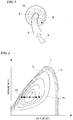
first crossing pipe 3 and the second crossing pipe 4 are disposed as described above, thefirst crossing pipe 3 and the second crossing pipe 4 require bent portions. As illustrated inFig. 2 , for example, thefirst crossing pipe 3 includes a plurality ofbent portions 5. - As illustrated in
Figs. 2 and3 , a connectingportion 6 of thefirst crossing pipe 3 with respect to the second high-pressure stage compressor 24 is formed such that the compressed air A introduced into the second high-pressure stage compressor 24 swirls in a rotational direction R of an impeller of the second high-pressure stage compressor 24. - Specifically, the
first crossing pipe 3 is formed so that an axial direction of the pipe in the connectingportion 6 is curved to follow the flow of the compressed air A flowing in the second high-pressure stage compressor 24. Thereby, a force is imparted to the compressed air A flowing in thefirst crossing pipe 3 such that a swirling motion is performed in a forward direction with respect to the rotational direction R of an impeller constituting the first high-pressure stage compressor 14. - Also, as in the
first crossing pipe 3, a connecting portion of the second crossing pipe 4 with respect to the first high-pressure stage compressor 14 is formed such that the compressed air A introduced into the first high-pressure stage compressor 14 swirls in a rotational direction of an impeller of the first high-pressure stage compressor 14. - Next, an operational flow of the engine system 1 of the present embodiment will be described.
- When temperatures and flow rates of the exhaust gas E discharged from the
first cylinder group 10 and the exhaust gas E discharged from thesecond cylinder group 20 are substantially the same, a pressure ratio (a compression ratio) between the first high-pressure stage compressor 14 and the first low-pressure stage compressor 16 and a pressure ratio between the second high-pressure stage compressor 24 and the second low-pressure stage compressor 26 are substantially the same, and then pressures at an outlet of the first high-pressure stage compressor and an outlet of the second high-pressure stage compressor 24 are substantially the same. That is, the pressures of the compressed air A supplied to thefirst cylinder group 10 and thesecond cylinder group 20 of the enginemain body 2 are increased to the same extent. - On the other hand, in some cases, the exhaust gas E discharged from the
first cylinder group 10 reaches a high temperature and high flow rate and outputs of the first high-pressure stage turbine 13 and the first low-pressure stage turbine 15 continue to increase while the exhaust gas E discharged from thesecond cylinder group 20 becomes a low temperature and low flow rate and outputs of the second high-pressure stage turbine 23 and the second low-pressure stage turbine 25 decrease. Description will be made with reference to a supercharging efficiency map (a map illustrating how much rotational energy of the turbine can be converted to a pressure increase by the compressor) for the efficiency reduction in such a case. -
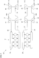
Fig. 4 is a view illustrating a supercharging efficiency map of a high-pressure stage supercharger. The horizontal axis inFig. 4 is an air flow rate. The vertical axis inFig. 4 is a pressure ratio, that is, a ratio of the air pressure immediately after flowing out from a compressor to the air pressure immediately before flowing into the compressor. A plurality of annular lines are efficiencies obtained from the correlation between the air flow rate and the pressure ratio, and the efficiency becomes higher as the line is closer to the center. Line S is a surge line and line C is a choke line. A region T surrounded by the surge line S and the choke line C is the operation region of the compressor. A center point P of the plurality of annular lines is the most efficient operating point. - Here, as a
conventional engine system 101 illustrated inFig. 5 , when a compressed air A discharged from a first low-pressure stage compressor 16 is introduced into a first high-pressure stage compressor 14 via a first low-pressurestage air pipe 103 and a compressed air A discharged from a second low-pressure stage compressor 26 is introduced into a second high-pressure stage compressor 24 via a second low-pressurestage air pipe 104, a large difference may occur in compression ratio of the compressed air A supplied to afirst cylinder group 10 and asecond cylinder group 20. - When an exhaust gas E with a high temperature and high flow rate is introduced into
exhaust pipes pressure stage compressor 16 moves to a P1 side. That is, the supercharger operates off the most efficient operating point P. While the compressed air A is introduced into the first high-pressure stage compressor 14 via the first low-pressurestage air pipe 103 and compressed, since the exhaust gas E introduced into a first high-pressure stage turbine 13 which drives the first high-pressure stage compressor 14 also has high temperature and high flow rate, degradation in efficiency is conceivable. - On the other hand, when an exhaust gas E with a low temperature and low flow rate is introduced into
exhaust pipes second cylinder group 20, an operating point of the second low-pressure stage compressor 26 moves to a P2 side. That is, it operates off the most efficient operating point. While the compressed air A is introduced into the second high-pressure stage compressor 24 via the second low-pressurestage air pipe 104 and compressed, since the exhaust gas E introduced into a second high-pressure stage turbine 23 which drives the second high-pressure stage compressor 24 also has low temperature and low flow rate, degradation in efficiency conceivable. - That is, in the piping configuration as illustrated in
Fig. 5 , when the exhaust energies of the exhaust gases E discharged from each of thecylinder groups - Also in the engine system 1 of the present embodiment, when a high temperature and high flow exhaust gas is introduced into the
exhaust pipes first cylinder group 10, a pressure of the compressed air A compressed by the first low-pressure stage compressor 16 increases and the operating point of the compressor moves to the P1 side. That is, it operates off the most efficient operating point. - On the other hand, when a low temperature and low flow rate exhaust gas is introduced into the
exhaust pipes second cylinder group 20, the operating point of the second low-pressure stage compressor 26 moves to the P2 side. That is, it operates off the most efficient operating point. - Here, the compressed air A discharged from the first low-
pressure stage compressor 16 is introduced into the second high-pressure stage compressor 24 via thefirst crossing pipe 3. Also, the compressed air A discharged from the second low-pressure stage compressor 26 is introduced into the first high-pressure stage compressor 14 via the second crossing pipe 4. - In other words, the compressed air compressed by the first low-
pressure stage compressor 16 of the right bank is compressed by the second high-pressure stage compressor 24 of the left bank and supplied to the engine. The compressed air A compressed by the second low-pressure stage compressor 26 of the left bank is compressed by the first high-pressure stage compressor 14 of the right bank and supplied to the engine. - The compressed air A compressed by the first low-
pressure stage compressor 16 having a high output is supplied to the second high-pressure stage compressor 24 having a low output. The compressed air A compressed by the second low-pressure stage compressor 26 having a low output is supplied to the first high-pressure stage compressor 14 having a high output. Thereby, a balance between the left and right cylinder groups improves. - According to the above-described embodiment, even when the exhaust energies of the exhaust gases discharged from the left bank and the right bank are different, it is possible to make the air-intake flow rate and the pressure ratio between the cylinder groups close to being equal to each other.
- Also, the connecting portions of the
crossing pipes 3 and 4 with respect to the high-pressure stage compressor pressure stage compressor pressure stage compressor - Although the embodiment of the present invention has been described in detail as above, various modifications can be made within the scope of the present invention without departing from the technical spirit of the present invention.
- The number of cylinder groups is not limited to two, and the engine system 1 may have a configuration in which three or more cylinder groups are provided, for example.
- According to the engine system described above, it is possible to make the air-supply flow rate and the pressure ratio between the cylinder groups close to being equal to each other even when exhaust energies of the exhaust gases discharged from a plurality of cylinder groups are different from each other.
-
- 1 Engine system
- 2 Engine main body
- 3 First crossing pipe
- 4 Second crossing pipe
- 5 Bent portion
- 6 Connecting portion
- 10 First cylinder group
- 11 First high-pressure stage supercharger
- 12 First low-pressure stage supercharger
- 13 First high-pressure stage turbine
- 14 First high-pressure stage compressor
- 15 First low-pressure stage turbine
- 16 First low-pressure stage compressor
- 17 First high-pressure stage exhaust pipe
- 18 First low-pressure stage exhaust pipe
- 19 First high-pressure stage air pipe
- 20 Second cylinder group
- 21 Second high-pressure stage supercharger
- 22 Second low-pressure stage supercharger
- 23 Second high-pressure stage turbine
- 24 Second high-pressure stage compressor
- 25 Second low-pressure stage turbine
- 26 Second low-pressure stage compressor
- 27 Second high-pressure stage exhaust pipe
- 28 Second low-pressure stage exhaust pipe
- 29 Second high-pressure stage air pipe
- A Compressed air
- E Exhaust gas
Claims (4)
- An engine system comprising:a plurality of cylinder groups which burn a supplied gas mixture and discharge an exhaust gas;a plurality of high-pressure stage superchargers each having a high-pressure stage turbine driven by the exhaust gas of the corresponding cylinder group, and a high-pressure stage compressor rotated by driving of the high-pressure stage turbine and configured to compress a gas supplied to the corresponding cylinder group; anda plurality of low-pressure stage superchargers each having a low-pressure stage turbine driven by an exhaust gas discharged from the high-pressure stage turbine of any one high-pressure stage supercharger of the plurality of high-pressure stage superchargers and a low-pressure stage compressor rotated by driving of the low-pressure stage turbine and configured to compress a gas supplied to a high-pressure stage compressor of a high-pressure stage supercharger other than the one high-pressure stage supercharger.
- An engine system comprising:a first cylinder group and a second cylinder group which burn a supplied gas mixture and discharge an exhaust gas;a first high-pressure stage supercharger and a second high-pressure stage supercharger each having a high-pressure stage turbine driven by the exhaust gas of the corresponding cylinder group and a high-pressure stage compressor rotated by driving of the high-pressure stage turbine and configured to compress a gas supplied to the corresponding cylinder group;a first low-pressure stage supercharger having a first low-pressure stage turbine driven by an exhaust gas discharged from the high-pressure stage turbine of the first high-pressure stage supercharger and a first low-pressure stage compressor rotated by driving of the first low-pressure stage turbine and configured to compress a gas supplied to the high-pressure stage compressor of the second high-pressure stage supercharger; anda second low-pressure stage supercharger having a second low-pressure stage turbine driven by an exhaust gas discharged from the high-pressure stage turbine of the second high-pressure stage supercharger and a second low-pressure stage compressor rotated by driving of the second low-pressure stage turbine and configured to compress a gas supplied to the high-pressure stage compressor of the first high-pressure stage supercharger.
- The engine system according to claim 1, wherein a pipe connecting the low-pressure stage compressor to the high-pressure stage compressor is formed so that the gas introduced into the high-pressure stage compressor swirls in a rotational direction of the high-pressure stage compressor.
- The engine system according to claim 2, wherein a pipe connecting the low-pressure stage compressor to the high-pressure stage compressor is formed so that the gas introduced into the high-pressure stage compressor swirls in a rotational direction of the high-pressure stage compressor.
Applications Claiming Priority (2)
| Application Number | Priority Date | Filing Date | Title |
|---|---|---|---|
| JP2015003072A JP6446705B2 (en) | 2015-01-09 | 2015-01-09 | Engine system |
| PCT/JP2016/050685 WO2016111375A1 (en) | 2015-01-09 | 2016-01-12 | Engine system |
Publications (3)
| Publication Number | Publication Date |
|---|---|
| EP3236043A1 true EP3236043A1 (en) | 2017-10-25 |
| EP3236043A4 EP3236043A4 (en) | 2018-01-24 |
| EP3236043B1 EP3236043B1 (en) | 2019-05-01 |
Family
ID=56356058
Family Applications (1)
| Application Number | Title | Priority Date | Filing Date |
|---|---|---|---|
| EP16735114.7A Active EP3236043B1 (en) | 2015-01-09 | 2016-01-12 | Engine system |
Country Status (5)
| Country | Link |
|---|---|
| US (1) | US10690044B2 (en) |
| EP (1) | EP3236043B1 (en) |
| JP (1) | JP6446705B2 (en) |
| CN (1) | CN107208532B (en) |
| WO (1) | WO2016111375A1 (en) |
Families Citing this family (2)
| Publication number | Priority date | Publication date | Assignee | Title |
|---|---|---|---|---|
| JP2018009980A (en) | 2016-06-29 | 2018-01-18 | 日本精工株式会社 | Weight measurement device of vehicle |
| US11156191B2 (en) * | 2019-11-22 | 2021-10-26 | Southwest Research Institute | Internal combustion engine with cross-boosting turbochargers |
Family Cites Families (31)
| Publication number | Priority date | Publication date | Assignee | Title |
|---|---|---|---|---|
| US1361365A (en) * | 1919-08-23 | 1920-12-07 | Charles A Campbell | Reflector |
| US2303949A (en) * | 1940-01-13 | 1942-12-01 | Carl H Nordell | Conduit bend |
| US2780053A (en) * | 1951-12-17 | 1957-02-05 | Napier & Son Ltd | Power units, including reciprocating internal combustion engines and turbo compressors utilizing exhaust gases from such engines |
| US2986327A (en) * | 1957-11-04 | 1961-05-30 | Fairchild Engine & Airplane | Axial flow centrifugal compressor and surge control system therefor |
| US3910715A (en) * | 1973-06-27 | 1975-10-07 | Worthington Pump Int | Side inlet means for centrifugal pumps |
| JPS55109726A (en) * | 1979-02-17 | 1980-08-23 | Kawasaki Heavy Ind Ltd | Method of and apparatus for cutting-off supercharger for diesel engine |
| US4685942A (en) * | 1982-12-27 | 1987-08-11 | General Electric Company | Axial flow inlet particle separator |
| US4638634A (en) * | 1985-10-04 | 1987-01-27 | The Garrett Corporation | Engine powered auxiliary air supply system |
| SU1361365A1 (en) * | 1986-05-15 | 1987-12-23 | Ростовский институт инженеров железнодорожного транспорта | Internal combustion engine |
| JP2912833B2 (en) * | 1994-10-07 | 1999-06-28 | 株式会社クボタ | Drain horizontal main pipe offset upper joint |
| GB2294729B (en) * | 1994-11-04 | 1999-02-24 | Gec Alsthom Diesels Ltd | A turbocharger assembly |
| JP2002115556A (en) * | 2000-10-03 | 2002-04-19 | Komatsu Ltd | Engine with two-stage supercharger |
| JP4295904B2 (en) | 2000-10-05 | 2009-07-15 | 株式会社小松製作所 | Multi-cylinder engine air supply structure |
| US6520738B2 (en) * | 2001-03-15 | 2003-02-18 | Honeywell International, Inc. | Plenum entry bulk swirl generator |
| US6672062B2 (en) * | 2001-12-21 | 2004-01-06 | Caterpillar Inc | Multi-stage supercharger arrangement with cross flow |
| US7165403B2 (en) * | 2004-07-28 | 2007-01-23 | Ford Global Technologies, Llc | Series/parallel turbochargers and switchable high/low pressure EGR for internal combustion engines |
| CN101027473A (en) * | 2004-09-21 | 2007-08-29 | 沃尔沃拉斯特瓦格纳公司 | Pipe line for a turbocharger system for an internal combustion engine |
| US20070036662A1 (en) * | 2005-08-05 | 2007-02-15 | C.R.F Societa Consortilla Per Azioni | Multistage motor-compressor for the compression of a fluid |
| US8449250B2 (en) * | 2007-10-19 | 2013-05-28 | Borgwarner Inc. | Duct for changing direction of flow, particularly for turbocharger compressor inlet |
| JP2009250068A (en) * | 2008-04-02 | 2009-10-29 | Toyota Motor Corp | Control device of multicylinder internal combustion engine |
| JP5451247B2 (en) * | 2008-09-10 | 2014-03-26 | ボーグワーナー インコーポレーテッド | Turbocharger connection for reverse rotation of passive pre-turn |
| JP2010281281A (en) * | 2009-06-05 | 2010-12-16 | Toyota Motor Corp | Supercharger and multistage supercharger provided with the same |
| JP5747483B2 (en) * | 2010-11-16 | 2015-07-15 | 株式会社Ihi | Low pressure loop EGR device |
| FI123429B (en) * | 2011-03-11 | 2013-04-30 | Waertsilae Finland Oy | Procedure for upgrading an engine, upgrade kit for an engine and internal combustion engine |
| JP5787790B2 (en) * | 2012-02-29 | 2015-09-30 | 三菱重工業株式会社 | Intake pipe structure of centrifugal fluid machinery |
| WO2014128896A1 (en) * | 2013-02-21 | 2014-08-28 | 三菱重工業株式会社 | Fluid machine and fluid machine system equipped with same |
| US9010117B2 (en) * | 2013-03-15 | 2015-04-21 | Cummins Inc. | Multi-stage turbocharger system with intercooling and aftercooling |
| US10094324B2 (en) * | 2013-05-30 | 2018-10-09 | General Electric Company | System and method of operating an internal combustion engine |
| DE102015203621A1 (en) * | 2015-03-02 | 2016-09-29 | Bayerische Motoren Werke Aktiengesellschaft | Two-stage turbocharger charging device for an internal combustion engine |
| JP6762724B2 (en) * | 2016-01-22 | 2020-09-30 | 三菱重工コンプレッサ株式会社 | Piping of driven fluid machinery |
| US11022355B2 (en) * | 2017-03-24 | 2021-06-01 | Johnson Controls Technology Company | Converging suction line for compressor |
-
2015
- 2015-01-09 JP JP2015003072A patent/JP6446705B2/en active Active
-
2016
- 2016-01-12 WO PCT/JP2016/050685 patent/WO2016111375A1/en not_active Ceased
- 2016-01-12 CN CN201680005060.XA patent/CN107208532B/en active Active
- 2016-01-12 US US15/541,888 patent/US10690044B2/en active Active
- 2016-01-12 EP EP16735114.7A patent/EP3236043B1/en active Active
Also Published As
| Publication number | Publication date |
|---|---|
| JP2016128657A (en) | 2016-07-14 |
| WO2016111375A1 (en) | 2016-07-14 |
| EP3236043B1 (en) | 2019-05-01 |
| CN107208532B (en) | 2020-04-28 |
| CN107208532A (en) | 2017-09-26 |
| US20180023458A1 (en) | 2018-01-25 |
| EP3236043A4 (en) | 2018-01-24 |
| US10690044B2 (en) | 2020-06-23 |
| JP6446705B2 (en) | 2019-01-09 |
Similar Documents
| Publication | Publication Date | Title |
|---|---|---|
| JPS5847226Y2 (en) | Two-stage supercharged reciprocating piston internal combustion engine | |
| JP4448853B2 (en) | Turbocharger system for an internal combustion engine consisting of a radial type compressor stage with a compressor wheel with swept blades | |
| US5564275A (en) | Method and apparatus for high-pressure end exhaust gas recirculation on a supercharged internal combustion engine | |
| US2780053A (en) | Power units, including reciprocating internal combustion engines and turbo compressors utilizing exhaust gases from such engines | |
| EP2683925B1 (en) | Method for upgrading an engine, upgrade kit for an engine and internal combustion engine | |
| CN202338390U (en) | Internal combustion engine | |
| US20120255299A1 (en) | V engine | |
| US6418723B1 (en) | Low pressure gaseous fuel system | |
| US10690044B2 (en) | Engine system | |
| CN102900535A (en) | Turbocharging gas turbine | |
| CN203098039U (en) | Two-stage turbocharger applicable to heavy-duty diesel engine | |
| CN1834421B (en) | Internal combustion engine | |
| WO2006033602A1 (en) | Pipe line for a turbocharger system for an internal combustion engine | |
| US6877317B2 (en) | Supercharging apparatus for an engine | |
| CN1175173C (en) | compressor unit for producing compressed air | |
| CN111164297B (en) | Internal combustion engine, motor vehicle with such internal combustion engine, and method for operating an internal combustion engine | |
| JP2012177329A (en) | Multistage supercharger structure | |
| CN104520550B (en) | Exhaust module and reciprocating engine | |
| US9581079B2 (en) | Two-stage turbocharger apparatus | |
| CN102777256A (en) | Impeller gas-compression gas compressor | |
| US10082153B2 (en) | Turbocharger compressor and method | |
| CN103967618A (en) | Turbine shaft engine | |
| CN103967617A (en) | Turboprop engine | |
| JP6027318B2 (en) | Multistage supercharging system | |
| CN110603376B (en) | Multi-stage supercharger |
Legal Events
| Date | Code | Title | Description |
|---|---|---|---|
| STAA | Information on the status of an ep patent application or granted ep patent |
Free format text: STATUS: THE INTERNATIONAL PUBLICATION HAS BEEN MADE |
|
| PUAI | Public reference made under article 153(3) epc to a published international application that has entered the european phase |
Free format text: ORIGINAL CODE: 0009012 |
|
| STAA | Information on the status of an ep patent application or granted ep patent |
Free format text: STATUS: REQUEST FOR EXAMINATION WAS MADE |
|
| 17P | Request for examination filed |
Effective date: 20170712 |
|
| AK | Designated contracting states |
Kind code of ref document: A1 Designated state(s): AL AT BE BG CH CY CZ DE DK EE ES FI FR GB GR HR HU IE IS IT LI LT LU LV MC MK MT NL NO PL PT RO RS SE SI SK SM TR |
|
| AX | Request for extension of the european patent |
Extension state: BA ME |
|
| A4 | Supplementary search report drawn up and despatched |
Effective date: 20171221 |
|
| RIC1 | Information provided on ipc code assigned before grant |
Ipc: F02B 37/007 20060101ALI20171215BHEP Ipc: F02B 37/013 20060101AFI20171215BHEP Ipc: F02B 37/00 20060101ALI20171215BHEP |
|
| DAV | Request for validation of the european patent (deleted) | ||
| DAX | Request for extension of the european patent (deleted) | ||
| STAA | Information on the status of an ep patent application or granted ep patent |
Free format text: STATUS: EXAMINATION IS IN PROGRESS |
|
| 17Q | First examination report despatched |
Effective date: 20180810 |
|
| GRAP | Despatch of communication of intention to grant a patent |
Free format text: ORIGINAL CODE: EPIDOSNIGR1 |
|
| STAA | Information on the status of an ep patent application or granted ep patent |
Free format text: STATUS: GRANT OF PATENT IS INTENDED |
|
| INTG | Intention to grant announced |
Effective date: 20181130 |
|
| GRAS | Grant fee paid |
Free format text: ORIGINAL CODE: EPIDOSNIGR3 |
|
| GRAA | (expected) grant |
Free format text: ORIGINAL CODE: 0009210 |
|
| STAA | Information on the status of an ep patent application or granted ep patent |
Free format text: STATUS: THE PATENT HAS BEEN GRANTED |
|
| RAP1 | Party data changed (applicant data changed or rights of an application transferred) |
Owner name: MITSUBISHI HEAVY INDUSTRIES, LTD. |
|
| AK | Designated contracting states |
Kind code of ref document: B1 Designated state(s): AL AT BE BG CH CY CZ DE DK EE ES FI FR GB GR HR HU IE IS IT LI LT LU LV MC MK MT NL NO PL PT RO RS SE SI SK SM TR |
|
| REG | Reference to a national code |
Ref country code: GB Ref legal event code: FG4D |
|
| REG | Reference to a national code |
Ref country code: CH Ref legal event code: EP Ref country code: AT Ref legal event code: REF Ref document number: 1127201 Country of ref document: AT Kind code of ref document: T Effective date: 20190515 |
|
| REG | Reference to a national code |
Ref country code: DE Ref legal event code: R096 Ref document number: 602016013275 Country of ref document: DE |
|
| REG | Reference to a national code |
Ref country code: IE Ref legal event code: FG4D |
|
| REG | Reference to a national code |
Ref country code: NL Ref legal event code: MP Effective date: 20190501 |
|
| REG | Reference to a national code |
Ref country code: LT Ref legal event code: MG4D |
|
| PG25 | Lapsed in a contracting state [announced via postgrant information from national office to epo] |
Ref country code: LT Free format text: LAPSE BECAUSE OF FAILURE TO SUBMIT A TRANSLATION OF THE DESCRIPTION OR TO PAY THE FEE WITHIN THE PRESCRIBED TIME-LIMIT Effective date: 20190501 Ref country code: HR Free format text: LAPSE BECAUSE OF FAILURE TO SUBMIT A TRANSLATION OF THE DESCRIPTION OR TO PAY THE FEE WITHIN THE PRESCRIBED TIME-LIMIT Effective date: 20190501 Ref country code: NL Free format text: LAPSE BECAUSE OF FAILURE TO SUBMIT A TRANSLATION OF THE DESCRIPTION OR TO PAY THE FEE WITHIN THE PRESCRIBED TIME-LIMIT Effective date: 20190501 Ref country code: NO Free format text: LAPSE BECAUSE OF FAILURE TO SUBMIT A TRANSLATION OF THE DESCRIPTION OR TO PAY THE FEE WITHIN THE PRESCRIBED TIME-LIMIT Effective date: 20190801 Ref country code: SE Free format text: LAPSE BECAUSE OF FAILURE TO SUBMIT A TRANSLATION OF THE DESCRIPTION OR TO PAY THE FEE WITHIN THE PRESCRIBED TIME-LIMIT Effective date: 20190501 Ref country code: FI Free format text: LAPSE BECAUSE OF FAILURE TO SUBMIT A TRANSLATION OF THE DESCRIPTION OR TO PAY THE FEE WITHIN THE PRESCRIBED TIME-LIMIT Effective date: 20190501 Ref country code: AL Free format text: LAPSE BECAUSE OF FAILURE TO SUBMIT A TRANSLATION OF THE DESCRIPTION OR TO PAY THE FEE WITHIN THE PRESCRIBED TIME-LIMIT Effective date: 20190501 Ref country code: PT Free format text: LAPSE BECAUSE OF FAILURE TO SUBMIT A TRANSLATION OF THE DESCRIPTION OR TO PAY THE FEE WITHIN THE PRESCRIBED TIME-LIMIT Effective date: 20190901 Ref country code: ES Free format text: LAPSE BECAUSE OF FAILURE TO SUBMIT A TRANSLATION OF THE DESCRIPTION OR TO PAY THE FEE WITHIN THE PRESCRIBED TIME-LIMIT Effective date: 20190501 |
|
| PG25 | Lapsed in a contracting state [announced via postgrant information from national office to epo] |
Ref country code: GR Free format text: LAPSE BECAUSE OF FAILURE TO SUBMIT A TRANSLATION OF THE DESCRIPTION OR TO PAY THE FEE WITHIN THE PRESCRIBED TIME-LIMIT Effective date: 20190802 Ref country code: BG Free format text: LAPSE BECAUSE OF FAILURE TO SUBMIT A TRANSLATION OF THE DESCRIPTION OR TO PAY THE FEE WITHIN THE PRESCRIBED TIME-LIMIT Effective date: 20190801 Ref country code: LV Free format text: LAPSE BECAUSE OF FAILURE TO SUBMIT A TRANSLATION OF THE DESCRIPTION OR TO PAY THE FEE WITHIN THE PRESCRIBED TIME-LIMIT Effective date: 20190501 Ref country code: RS Free format text: LAPSE BECAUSE OF FAILURE TO SUBMIT A TRANSLATION OF THE DESCRIPTION OR TO PAY THE FEE WITHIN THE PRESCRIBED TIME-LIMIT Effective date: 20190501 |
|
| PG25 | Lapsed in a contracting state [announced via postgrant information from national office to epo] |
Ref country code: IS Free format text: LAPSE BECAUSE OF FAILURE TO SUBMIT A TRANSLATION OF THE DESCRIPTION OR TO PAY THE FEE WITHIN THE PRESCRIBED TIME-LIMIT Effective date: 20190901 |
|
| PG25 | Lapsed in a contracting state [announced via postgrant information from national office to epo] |
Ref country code: EE Free format text: LAPSE BECAUSE OF FAILURE TO SUBMIT A TRANSLATION OF THE DESCRIPTION OR TO PAY THE FEE WITHIN THE PRESCRIBED TIME-LIMIT Effective date: 20190501 Ref country code: DK Free format text: LAPSE BECAUSE OF FAILURE TO SUBMIT A TRANSLATION OF THE DESCRIPTION OR TO PAY THE FEE WITHIN THE PRESCRIBED TIME-LIMIT Effective date: 20190501 Ref country code: RO Free format text: LAPSE BECAUSE OF FAILURE TO SUBMIT A TRANSLATION OF THE DESCRIPTION OR TO PAY THE FEE WITHIN THE PRESCRIBED TIME-LIMIT Effective date: 20190501 Ref country code: CZ Free format text: LAPSE BECAUSE OF FAILURE TO SUBMIT A TRANSLATION OF THE DESCRIPTION OR TO PAY THE FEE WITHIN THE PRESCRIBED TIME-LIMIT Effective date: 20190501 Ref country code: SK Free format text: LAPSE BECAUSE OF FAILURE TO SUBMIT A TRANSLATION OF THE DESCRIPTION OR TO PAY THE FEE WITHIN THE PRESCRIBED TIME-LIMIT Effective date: 20190501 |
|
| REG | Reference to a national code |
Ref country code: DE Ref legal event code: R097 Ref document number: 602016013275 Country of ref document: DE |
|
| PG25 | Lapsed in a contracting state [announced via postgrant information from national office to epo] |
Ref country code: SM Free format text: LAPSE BECAUSE OF FAILURE TO SUBMIT A TRANSLATION OF THE DESCRIPTION OR TO PAY THE FEE WITHIN THE PRESCRIBED TIME-LIMIT Effective date: 20190501 Ref country code: IT Free format text: LAPSE BECAUSE OF FAILURE TO SUBMIT A TRANSLATION OF THE DESCRIPTION OR TO PAY THE FEE WITHIN THE PRESCRIBED TIME-LIMIT Effective date: 20190501 |
|
| PLBE | No opposition filed within time limit |
Free format text: ORIGINAL CODE: 0009261 |
|
| STAA | Information on the status of an ep patent application or granted ep patent |
Free format text: STATUS: NO OPPOSITION FILED WITHIN TIME LIMIT |
|
| PG25 | Lapsed in a contracting state [announced via postgrant information from national office to epo] |
Ref country code: TR Free format text: LAPSE BECAUSE OF FAILURE TO SUBMIT A TRANSLATION OF THE DESCRIPTION OR TO PAY THE FEE WITHIN THE PRESCRIBED TIME-LIMIT Effective date: 20190501 |
|
| 26N | No opposition filed |
Effective date: 20200204 |
|
| PG25 | Lapsed in a contracting state [announced via postgrant information from national office to epo] |
Ref country code: PL Free format text: LAPSE BECAUSE OF FAILURE TO SUBMIT A TRANSLATION OF THE DESCRIPTION OR TO PAY THE FEE WITHIN THE PRESCRIBED TIME-LIMIT Effective date: 20190501 |
|
| PG25 | Lapsed in a contracting state [announced via postgrant information from national office to epo] |
Ref country code: SI Free format text: LAPSE BECAUSE OF FAILURE TO SUBMIT A TRANSLATION OF THE DESCRIPTION OR TO PAY THE FEE WITHIN THE PRESCRIBED TIME-LIMIT Effective date: 20190501 |
|
| PG25 | Lapsed in a contracting state [announced via postgrant information from national office to epo] |
Ref country code: MC Free format text: LAPSE BECAUSE OF FAILURE TO SUBMIT A TRANSLATION OF THE DESCRIPTION OR TO PAY THE FEE WITHIN THE PRESCRIBED TIME-LIMIT Effective date: 20190501 |
|
| REG | Reference to a national code |
Ref country code: CH Ref legal event code: PL |
|
| REG | Reference to a national code |
Ref country code: BE Ref legal event code: MM Effective date: 20200131 |
|
| PG25 | Lapsed in a contracting state [announced via postgrant information from national office to epo] |
Ref country code: LU Free format text: LAPSE BECAUSE OF NON-PAYMENT OF DUE FEES Effective date: 20200112 |
|
| PG25 | Lapsed in a contracting state [announced via postgrant information from national office to epo] |
Ref country code: LI Free format text: LAPSE BECAUSE OF NON-PAYMENT OF DUE FEES Effective date: 20200131 Ref country code: CH Free format text: LAPSE BECAUSE OF NON-PAYMENT OF DUE FEES Effective date: 20200131 Ref country code: BE Free format text: LAPSE BECAUSE OF NON-PAYMENT OF DUE FEES Effective date: 20200131 |
|
| REG | Reference to a national code |
Ref country code: AT Ref legal event code: UEP Ref document number: 1127201 Country of ref document: AT Kind code of ref document: T Effective date: 20190501 |
|
| PG25 | Lapsed in a contracting state [announced via postgrant information from national office to epo] |
Ref country code: IE Free format text: LAPSE BECAUSE OF NON-PAYMENT OF DUE FEES Effective date: 20200112 |
|
| PG25 | Lapsed in a contracting state [announced via postgrant information from national office to epo] |
Ref country code: FR Free format text: LAPSE BECAUSE OF NON-PAYMENT OF DUE FEES Effective date: 20200131 |
|
| PG25 | Lapsed in a contracting state [announced via postgrant information from national office to epo] |
Ref country code: MT Free format text: LAPSE BECAUSE OF FAILURE TO SUBMIT A TRANSLATION OF THE DESCRIPTION OR TO PAY THE FEE WITHIN THE PRESCRIBED TIME-LIMIT Effective date: 20190501 Ref country code: CY Free format text: LAPSE BECAUSE OF FAILURE TO SUBMIT A TRANSLATION OF THE DESCRIPTION OR TO PAY THE FEE WITHIN THE PRESCRIBED TIME-LIMIT Effective date: 20190501 |
|
| PG25 | Lapsed in a contracting state [announced via postgrant information from national office to epo] |
Ref country code: MK Free format text: LAPSE BECAUSE OF FAILURE TO SUBMIT A TRANSLATION OF THE DESCRIPTION OR TO PAY THE FEE WITHIN THE PRESCRIBED TIME-LIMIT Effective date: 20190501 |
|
| PGFP | Annual fee paid to national office [announced via postgrant information from national office to epo] |
Ref country code: GB Payment date: 20251127 Year of fee payment: 11 |
|
| PGFP | Annual fee paid to national office [announced via postgrant information from national office to epo] |
Ref country code: DE Payment date: 20251203 Year of fee payment: 11 |
|
| PGFP | Annual fee paid to national office [announced via postgrant information from national office to epo] |
Ref country code: AT Payment date: 20251230 Year of fee payment: 11 |