EP3235700B1 - System and method of estimating an indication of the driving style of a motor vehicle - Google Patents
System and method of estimating an indication of the driving style of a motor vehicle Download PDFInfo
- Publication number
- EP3235700B1 EP3235700B1 EP17162835.7A EP17162835A EP3235700B1 EP 3235700 B1 EP3235700 B1 EP 3235700B1 EP 17162835 A EP17162835 A EP 17162835A EP 3235700 B1 EP3235700 B1 EP 3235700B1
- Authority
- EP
- European Patent Office
- Prior art keywords
- motor vehicle
- energy
- value
- space
- measuring
- Prior art date
- Legal status (The legal status is an assumption and is not a legal conclusion. Google has not performed a legal analysis and makes no representation as to the accuracy of the status listed.)
- Not-in-force
Links
Images

Classifications
-
- G—PHYSICS
- G07—CHECKING-DEVICES
- G07C—TIME OR ATTENDANCE REGISTERS; REGISTERING OR INDICATING THE WORKING OF MACHINES; GENERATING RANDOM NUMBERS; VOTING OR LOTTERY APPARATUS; ARRANGEMENTS, SYSTEMS OR APPARATUS FOR CHECKING NOT PROVIDED FOR ELSEWHERE
- G07C5/00—Registering or indicating the working of vehicles
- G07C5/02—Registering or indicating driving, working, idle, or waiting time only
-
- B—PERFORMING OPERATIONS; TRANSPORTING
- B60—VEHICLES IN GENERAL
- B60W—CONJOINT CONTROL OF VEHICLE SUB-UNITS OF DIFFERENT TYPE OR DIFFERENT FUNCTION; CONTROL SYSTEMS SPECIALLY ADAPTED FOR HYBRID VEHICLES; ROAD VEHICLE DRIVE CONTROL SYSTEMS FOR PURPOSES NOT RELATED TO THE CONTROL OF A PARTICULAR SUB-UNIT
- B60W40/00—Estimation or calculation of non-directly measurable driving parameters for road vehicle drive control systems not related to the control of a particular sub unit, e.g. by using mathematical models
- B60W40/08—Estimation or calculation of non-directly measurable driving parameters for road vehicle drive control systems not related to the control of a particular sub unit, e.g. by using mathematical models related to drivers or passengers
- B60W40/09—Driving style or behaviour
-
- G—PHYSICS
- G01—MEASURING; TESTING
- G01S—RADIO DIRECTION-FINDING; RADIO NAVIGATION; DETERMINING DISTANCE OR VELOCITY BY USE OF RADIO WAVES; LOCATING OR PRESENCE-DETECTING BY USE OF THE REFLECTION OR RERADIATION OF RADIO WAVES; ANALOGOUS ARRANGEMENTS USING OTHER WAVES
- G01S19/00—Satellite radio beacon positioning systems; Determining position, velocity or attitude using signals transmitted by such systems
- G01S19/38—Determining a navigation solution using signals transmitted by a satellite radio beacon positioning system
- G01S19/39—Determining a navigation solution using signals transmitted by a satellite radio beacon positioning system the satellite radio beacon positioning system transmitting time-stamped messages, e.g. GPS [Global Positioning System], GLONASS [Global Orbiting Navigation Satellite System] or GALILEO
- G01S19/52—Determining velocity
-
- B—PERFORMING OPERATIONS; TRANSPORTING
- B60—VEHICLES IN GENERAL
- B60W—CONJOINT CONTROL OF VEHICLE SUB-UNITS OF DIFFERENT TYPE OR DIFFERENT FUNCTION; CONTROL SYSTEMS SPECIALLY ADAPTED FOR HYBRID VEHICLES; ROAD VEHICLE DRIVE CONTROL SYSTEMS FOR PURPOSES NOT RELATED TO THE CONTROL OF A PARTICULAR SUB-UNIT
- B60W2510/00—Input parameters relating to a particular sub-units
- B60W2510/06—Combustion engines, Gas turbines
- B60W2510/0614—Position of fuel or air injector
- B60W2510/0623—Fuel flow rate
-
- B—PERFORMING OPERATIONS; TRANSPORTING
- B60—VEHICLES IN GENERAL
- B60W—CONJOINT CONTROL OF VEHICLE SUB-UNITS OF DIFFERENT TYPE OR DIFFERENT FUNCTION; CONTROL SYSTEMS SPECIALLY ADAPTED FOR HYBRID VEHICLES; ROAD VEHICLE DRIVE CONTROL SYSTEMS FOR PURPOSES NOT RELATED TO THE CONTROL OF A PARTICULAR SUB-UNIT
- B60W2520/00—Input parameters relating to overall vehicle dynamics
- B60W2520/10—Longitudinal speed
-
- B—PERFORMING OPERATIONS; TRANSPORTING
- B60—VEHICLES IN GENERAL
- B60W—CONJOINT CONTROL OF VEHICLE SUB-UNITS OF DIFFERENT TYPE OR DIFFERENT FUNCTION; CONTROL SYSTEMS SPECIALLY ADAPTED FOR HYBRID VEHICLES; ROAD VEHICLE DRIVE CONTROL SYSTEMS FOR PURPOSES NOT RELATED TO THE CONTROL OF A PARTICULAR SUB-UNIT
- B60W2530/00—Input parameters relating to vehicle conditions or values, not covered by groups B60W2510/00 or B60W2520/00
- B60W2530/13—Mileage
-
- B—PERFORMING OPERATIONS; TRANSPORTING
- B60—VEHICLES IN GENERAL
- B60W—CONJOINT CONTROL OF VEHICLE SUB-UNITS OF DIFFERENT TYPE OR DIFFERENT FUNCTION; CONTROL SYSTEMS SPECIALLY ADAPTED FOR HYBRID VEHICLES; ROAD VEHICLE DRIVE CONTROL SYSTEMS FOR PURPOSES NOT RELATED TO THE CONTROL OF A PARTICULAR SUB-UNIT
- B60W2530/00—Input parameters relating to vehicle conditions or values, not covered by groups B60W2510/00 or B60W2520/00
- B60W2530/18—Distance travelled
Definitions
- the present invention refers to techniques for estimating the driving style of a motor vehicle adopted by a driver.
- Document WO-2011-101713 describes a method of estimating the driving style based on calculating an index obtained by the ratio between the difference of an energy consumed by the motor vehicle and a reference energy, and the reference energy itself.
- Application EP-A-1780090 describes a method for defining the driving style of a motor vehicle driver, which comprises monitoring different magnitudes, among them: how many times the horn is used, the speed variation, the accelerator position variation, the angular speed obtained by the movements of the driving wheel. Then, the estimate is based on calculating the differences between these monitored magnitudes and predetermined threshold values.
- Patent application EP-A-0777071 describes a method of controlling the automatic transmission of a vehicle as a function of the driving style of the driver based, among the other things, on the following information: opening of the fuel valve, vehicle speed, angular speed of the engine.
- Patent application EP-A-1498297 describes a method of estimating the fuel consumption which instrumental in monitoring different magnitudes, among them there are: a signal of the rotation speed of the motive wheel, a signal of the rotation speed of the driving shaft, a cooling temperature signal, a fuel temperature signal.
- the Applicant has noted that the standard techniques of estimating the driving style are not satisfying because sometimes they do not enable to distinguish possible different behaviors of the drivers of a vehicle.
- the object of the present invention is to provide a technique for estimating the driving style of motor vehicles which is adequately reliable.
- the object of the present invention is met by a system for estimating the driving style as defined in claim 1.
- Preferred embodiments are defined in the dependent claims from 2 to 9. It is also an object of the invention a method of estimating the driving style as defined in claim 10.
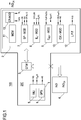
- Figure 1 shows an example of a system 100 for estimating the driving style of a driver of a motor vehicle.
- the estimating system 100 comprises a measuring apparatus 1 and a processing apparatus 2 adapted to communicate with each other.
- the estimating system 100 is also provided with a gateway device 3 (GTW) and with at least one presentation or report device 4 showing the results of the performed estimate.
- GTW gateway device 3
- the measuring apparatus 1 is mounted on the motor vehicle and enables to provide electric signals, particularly digital signals, representative of cinematic magnitudes associated to the motion of the motor vehicle itself.
- the digital signals supplied by the measuring apparatus 1 can be a signal of the speed of the motor vehicle and, for example, also an acceleration signal of the motor vehicle itself.
- the measuring apparatus 1 can supply electric signals in an analog form which can be digitally converted for enabling, for example, numerical processings executed by a software.
- the measuring apparatus 1 can comprise a speed transducer and acceleration transducer of the motor vehicle.
- the signals acquisition apparatus 1 is provided, for example, with an inertial measuring system 5 (IMU), per se known (known in the field as “inertial platform”), which comprises a computer and motion sensors adapted to supply the acceleration and speed signals (in terms of direction, sense and amplitude) of the motor vehicle.
- IMU inertial measuring system 5
- the measuring apparatus 1 can be also provided with a positioning device 6 (GPS) such as a receiver operating in a satellite positioning system such as, particularly, the GPS (Global Positioning System).
- GPS Global Positioning System
- the receiver GPS 6 is capable of supplying, in addition to the motor vehicle position, also an associated speed signal.
- a data processing unit or a computer (provided with memories, computing units and interfaces communicating with the outer environment) adapted to receive the signals from the measuring apparatus 1 and to execute computing and processing operations for estimating the driving style of a particular driver of the motor vehicle.
- the processing apparatus 2 particularly comprises a microcontroller.
- the data processing unit 2 comprises the following modules (of a software type, for example): a space computing module 7 (SP-MOD), a consumed energy computing module 8 (Eu-MOD), a reference energy computing module 9 (E REF -MOD), and an index computing module 10 (IDX-MOD).
- SP-MOD space computing module 7
- EU-MOD consumed energy computing module 8
- E REF -MOD reference energy computing module 9
- IDX-MOD index computing module
- the space computing module 7 is configured for calculating the space (i.e. a distance) travelled by the motor vehicle along a measuring path.
- the consumed energy computing module 8 is configured for estimating an energy Eu consumed by the motor vehicle along the measuring path.
- the reference energy computing module 9 is configured for estimating a reference energy E REF associated to a reference (or ideal) behavior of the motor vehicle along the measuring path.
- the index computing module 10 is configured for providing an index IND of the driving style of the motor vehicle. Particularly, the index computing module 10 calculates such index IND based on a difference between the used energy Eu and reference energy E REF and considering the travelled space.
- the data processing unit 2 comprises, for example, a measured data memory 11 (MEM) and a low-pass filtering module 12 (LPF).
- MEM measured data memory 11
- LPF low-pass filtering module 12
- the data processing unit 2 can be mounted in the vehicle or can be remote from it and placed, for example, in a monitoring station.
- the data processing unit 2, measuring unit 1 and gateway 3 can be integrated in a single apparatus 200 which, preferably, implements a control unit mounted to the motor vehicle.
- the gateway 3 ensures the communication between the apparatus 200, particularly the data processing unit 2, and the one or more report modules 4.
- the gateway 3 ensures the communication by using a short range transmission (wireless based on the Wi-Fi, Bluetooth technology, for example).
- a short range transmission wireless based on the Wi-Fi, Bluetooth technology, for example.
- the report module 4 is a web-console, it exchanges data/information with the apparatus 200 by using a long range transmission (based on the GPRS, UMTS, LTE technologies, for example).
- the report module 4 is a device mounted to the motor vehicle, it can be connected by wiring to the apparatus 200.
- the estimating system 100 can comprise more than one report module 4: at least one smartphone and/or at least one web-console and/or at least one device mounted to the motor vehicle.
- the report device 4 comprises, preferably, a display adapted to show information enabling the driver or other users to know the result of the estimate of the driving style.
- the connection between the measuring unit 1 and data processing unit 2 can be ensured by the gateway 3, by using a low range or long range transmission technology according to the distance between the two apparatuses.
- a threshold value of the space S th for estimating the driving style is defined.
- the index IND representative of the driving style preferably will be calculated by considering values of the consumed energy Eu and of the reference energy E REF corresponding to a path travelled by the motor vehicle, equal to the space threshold value S th .
- the space computing module 7 detects, based on signals from the measuring apparatus 1, when the motor vehicle has travelled a space equal to the threshold value S th .
- the threshold value S th can be of 2 km, for example.
- the space computing module 7 uses a first speed signal v gps (t), provided by the GPS 6. For example, the space computing module 7 periodically integrates over time the first speed signal v gps (t) for obtaining a current value of the space s(t).
- formula (1) can be calculated by the data processing unit 2 by a Tustin transformation (per se known to the person skilled in the art) on signals sampled, for example, at 10 Hz.
- the space computing module 7 communicates such event, for example, to the index computing module 10, as an alert signal SP-AL.
- the consumed energy computing module 8 performs an energy estimate Eu(t) consumed by the motor vehicle along a path of length S th by using a speed signal v(t). For example, the speed signal v(t) is obtained by the measuring apparatus 1.
- P engine t M a t ⁇ t + F res ⁇ t
- the first term of formula (3) is the inertial power, while the second term is the power generated by the resisting forces.
- the Applicant has observed that by considering only the inertial factor when calculating the driving style, uniform indexes of the driving style are obtained both in an urban environment and in the suburban one. Indeed, in an urban environment, the driving sessions are characterized by continuous brakings and accelerations, which account for the main portion of the consumed energy. By contrast, in a suburban environment, the energy contribution for overcoming the frictions, takes an importance comparable to the inertial contribution. Since the object of the index consists of evaluating the driver driving style, it makes sense considering only the component of the energy on which the driver has a real decisional power, in other words managing the speed and acceleration.
- the consumed energy computing module 8 based on formulas (3) and (5) or, preferably, (4) and (5), performs a numerical processing of the available digital data and estimates the inertial energy E U consumed by the engine of the motor vehicle.
- an acceleration signal representative of the acceleration a(t) which can be provided by the inertial measurement system 5 or can be obtained by a time derivative of the speed signal v(t), in turn provided by the receiver GPS 6.
- the reference energy computing module 9 estimates the reference energy E REF (t) which represents the energy the motor vehicle engine could consume when the motor vehicle is driven according to a reference trend.
- such reference trend of the motor vehicle is associated to a reference trend of a cinematic magnitude.
- such reference cinematic magnitude can be the motor vehicle speed.
- it is selected as motor vehicle speed a filtered speed v F (t) obtained by low-pass filtering the measured speed v(t) obtained as a function of values provided by the receiver GPS 6.
- the time instant t1 is the one in which the motor vehicle travels a space equal to the threshold value S th . Therefore, the value of the time instant t1 can be supplied to the reference energy computing module 9 by the space computing module 7.
- the processing unit 2 can make available this index IND to the report device 4 so that it can be shown also to the driver.
- the values of the index of the driving style IND can be calculated every time the space S th is travelled and at each stop of the motor vehicle, the worst value (in other words the highest) among the ones obtained, is supplied.
- IND PA E U t 1 ⁇ E REF t 1 E REF t 1
- the numerator is the difference between the inertial energies (consumed energy Eu(t1) and reference energy E REF (t1)) and the denominator is the reference energy E REF (t1).
- Figure 2a shows a first curve C1 regarding the trend of the measured speed v(t) by which a motor vehicle is driven.
- the second curve C2 instead is the trend of the reference speed v REF (t), obtained by low-pass filtering the measured one.
- Figure 2b shows a third curve C3 corresponding to another trend of the speed v(t) by which a motor vehicle is driven.
- the force curve C4 is the trend of the reference speed v REF (t) obtained by low-pass filtering the speed of the third curve C3.
- the index IND PA according to the formula (11) has the same result in both cases, so that does not enable to distinguish the two behaviors.
- the index of the driving style IND according to the formula (9), supplies different results in the two cases, so that the driving style in Figure 2b ) is better than the one shown in Figure 2a ).
- the speed signal v(t) used for calculating the consumed energy Eu(t) and also, for example, for the reference energy E REF (t) (by low-pass filtering) can be obtained by the frequency separation technique in order to construct a speed signal which takes account of the information contents provided both by the receiver GPS 6 and the inertial accelerometer 5.
- Document WO-2011-101713 describes, with reference to the associated Figure 5, a possible frequency separation technique. This frequency separation technique can be implemented by an associated software module present in the processing unit 2.
- Such low-pass filtering can be implemented by a low-pass filter of the first digital order with signals sampled at 10 Hz.
- the processing unit 2 comprises an index correcting module 13 (CR-MOD) configured to modify the value of the index IND calculated by the index computing module 10 based on a correction value which takes account of the average slope associated to a path travelled by the motor vehicle.
- the index correction module 13 is particularly advantageous when the motor vehicle moves in a mountain environment.
- the index correcting module 13 receives from the measuring apparatus 1 (particularly from the device GPS 6) a signal representative of the altitude alt(t) of the motor vehicle.
- this altitude signal alt(t) is low-pass filtered to obtain a filtered altitude signal alt F (t). Filtering enables to cancel the noise and can be performed by the index correcting module 13 itself, in the same way as was described with reference to the low-pass filtering module 12.
- the index correcting module 13 calculates an "unwrapped" altitude value A UNW indicating when the travelled path comprises altitude variations.
- Formula (12) shows the unwrapped altitude A UNW obtained by the integration of the absolute value of the derivative of the filtered altitude alt F (t). Using the absolute value of the derivative does not enable the ascending and descending paths (having derivatives of opposite sign) to supply contributions which cancel with each other without concurring to the calculation of the unwrapped altitude A UNW .
- the integration of formula (12) is extended between two time intervals (a time window) which can be coincident with the time interval wherein the values of the estimate index IND are given.
- the index correcting module 13 places the travelled space value Sp of the vehicle between the time instants corresponding to the ones of the unwrapped altitude A UNW calculation. For example, the travelled space Sp coincides with the space threshold value S th .
- the travelled space Sp can be obtained by the space computing module 7, as described with reference to formula (1).
- the average slope P M (which can be also expressed as a percentage) is used by the index correcting module 13 for modifying the calculated value of the estimate index IND for taking account of the fact the motor vehicle is driven in an environment with altitude variations.
- the index correcting module 13 modifies the index value IND calculated by formula (9), for obtaining a corrected index IND CR . This modification is done for reducing the value of such index as the average slope P M increases.
- IND CR IND ⁇ ⁇ ⁇ P M
- results of the estimate are also available to a monitoring station wherein further calculations and statistics are made, and reports regarding the driver behavior are generated.
- the described system for estimating the driving style is particularly advantageous because enables to obtain an index of the driving style (IND) more realistically expressing the behavior of a driver, than what is obtainable by means of the prior art systems. Moreover, obtaining the corrected index IND CR enables to provide a reliable evaluation of the driving style also in a mountain environment.
- IND index of the driving style
Landscapes
- Engineering & Computer Science (AREA)
- Physics & Mathematics (AREA)
- Radar, Positioning & Navigation (AREA)
- Remote Sensing (AREA)
- General Physics & Mathematics (AREA)
- Automation & Control Theory (AREA)
- Mathematical Physics (AREA)
- Transportation (AREA)
- Mechanical Engineering (AREA)
- Computer Networks & Wireless Communication (AREA)
- Electric Propulsion And Braking For Vehicles (AREA)
- Control Of Driving Devices And Active Controlling Of Vehicle (AREA)
Description
- The present invention refers to techniques for estimating the driving style of a motor vehicle adopted by a driver.
- Different techniques of estimating the driving style of motor vehicle drivers to be used with reference to an estimate of the fuel consumption, safety of the driver behavior, or for generally evaluating his/her driving capabilities, are known.
- Document
WO-2011-101713 describes a method of estimating the driving style based on calculating an index obtained by the ratio between the difference of an energy consumed by the motor vehicle and a reference energy, and the reference energy itself. - Application
EP-A-1780090 describes a method for defining the driving style of a motor vehicle driver, which comprises monitoring different magnitudes, among them: how many times the horn is used, the speed variation, the accelerator position variation, the angular speed obtained by the movements of the driving wheel. Then, the estimate is based on calculating the differences between these monitored magnitudes and predetermined threshold values. - Patent application
EP-A-0777071 describes a method of controlling the automatic transmission of a vehicle as a function of the driving style of the driver based, among the other things, on the following information: opening of the fuel valve, vehicle speed, angular speed of the engine. - Patent application
EP-A-1498297 describes a method of estimating the fuel consumption which instrumental in monitoring different magnitudes, among them there are: a signal of the rotation speed of the motive wheel, a signal of the rotation speed of the driving shaft, a cooling temperature signal, a fuel temperature signal. - The Applicant has noted that the standard techniques of estimating the driving style are not satisfying because sometimes they do not enable to distinguish possible different behaviors of the drivers of a vehicle.
- The object of the present invention is to provide a technique for estimating the driving style of motor vehicles which is adequately reliable.
- The object of the present invention is met by a system for estimating the driving style as defined in claim 1. Preferred embodiments are defined in the dependent claims from 2 to 9. It is also an object of the invention a method of estimating the driving style as defined in
claim 10. - Further characteristics and advantages of the invention will result from the following description of a preferred embodiment and variants thereof illustratively given with reference to the attached drawings, wherein:
-
Figure 1 schematically shows an example of a system for estimating the driving style of a driver of a motor vehicle; -
Figure 2a ) shows the trend of the measured speed and reference speed with respect to a first driving example of a motor vehicle; -
Figure 2b ) shows the trend of the measured speed and reference speed with respect to a second driving example of a motor vehicle. -
Figure 1 shows an example of asystem 100 for estimating the driving style of a driver of a motor vehicle. Particularly, the estimatingsystem 100 comprises a measuring apparatus 1 and aprocessing apparatus 2 adapted to communicate with each other. Specifically, theestimating system 100 is also provided with a gateway device 3 (GTW) and with at least one presentation or report device 4 showing the results of the performed estimate. - Preferably, the measuring apparatus 1 is mounted on the motor vehicle and enables to provide electric signals, particularly digital signals, representative of cinematic magnitudes associated to the motion of the motor vehicle itself. The digital signals supplied by the measuring apparatus 1 can be a signal of the speed of the motor vehicle and, for example, also an acceleration signal of the motor vehicle itself. As an alternative, the measuring apparatus 1 can supply electric signals in an analog form which can be digitally converted for enabling, for example, numerical processings executed by a software.
- According to a particular embodiment, the measuring apparatus 1 can comprise a speed transducer and acceleration transducer of the motor vehicle. To this purpose, the signals acquisition apparatus 1 is provided, for example, with an inertial measuring system 5 (IMU), per se known (known in the field as "inertial platform"), which comprises a computer and motion sensors adapted to supply the acceleration and speed signals (in terms of direction, sense and amplitude) of the motor vehicle.
- Moreover, advantageously, the measuring apparatus 1 can be also provided with a positioning device 6 (GPS) such as a receiver operating in a satellite positioning system such as, particularly, the GPS (Global Positioning System). The receiver GPS 6 is capable of supplying, in addition to the motor vehicle position, also an associated speed signal.
- With reference to the
processing apparatus 2, this is, according to an embodiment, a data processing unit or a computer (provided with memories, computing units and interfaces communicating with the outer environment) adapted to receive the signals from the measuring apparatus 1 and to execute computing and processing operations for estimating the driving style of a particular driver of the motor vehicle. Theprocessing apparatus 2 particularly comprises a microcontroller. - According to the schematic view in
Figure 1 , thedata processing unit 2 comprises the following modules (of a software type, for example): a space computing module 7 (SP-MOD), a consumed energy computing module 8 (Eu-MOD), a reference energy computing module 9 (EREF-MOD), and an index computing module 10 (IDX-MOD). - Particularly, the
space computing module 7 is configured for calculating the space (i.e. a distance) travelled by the motor vehicle along a measuring path. The consumed energy computing module 8 is configured for estimating an energy Eu consumed by the motor vehicle along the measuring path. - Moreover, the reference energy computing module 9 is configured for estimating a reference energy EREF associated to a reference (or ideal) behavior of the motor vehicle along the measuring path.
- The
index computing module 10 is configured for providing an index IND of the driving style of the motor vehicle. Particularly, theindex computing module 10 calculates such index IND based on a difference between the used energy Eu and reference energy EREF and considering the travelled space. - Moreover, the
data processing unit 2 comprises, for example, a measured data memory 11 (MEM) and a low-pass filtering module 12 (LPF). - The
data processing unit 2 can be mounted in the vehicle or can be remote from it and placed, for example, in a monitoring station. - Particularly, the
data processing unit 2, measuring unit 1 and gateway 3 can be integrated in asingle apparatus 200 which, preferably, implements a control unit mounted to the motor vehicle. - The gateway 3 ensures the communication between the
apparatus 200, particularly thedata processing unit 2, and the one or more report modules 4. For example, if the report module 4 is a smartphone or another mobile device, the gateway 3 ensures the communication by using a short range transmission (wireless based on the Wi-Fi, Bluetooth technology, for example). Particularly, when the report module 4 is a web-console, it exchanges data/information with theapparatus 200 by using a long range transmission (based on the GPRS, UMTS, LTE technologies, for example). According to another example, if the report module 4 is a device mounted to the motor vehicle, it can be connected by wiring to theapparatus 200. The estimatingsystem 100 can comprise more than one report module 4: at least one smartphone and/or at least one web-console and/or at least one device mounted to the motor vehicle. - In any case, the report device 4 comprises, preferably, a display adapted to show information enabling the driver or other users to know the result of the estimate of the driving style.
- According to another example, when the
data processing unit 2 is placed remotely from the measuring unit 1, the connection between the measuring unit 1 anddata processing unit 2 can be ensured by the gateway 3, by using a low range or long range transmission technology according to the distance between the two apparatuses. - An example of an operation of the driving
style estimating system 100 will be now described. A threshold value of the space Sth for estimating the driving style is defined. The index IND representative of the driving style preferably will be calculated by considering values of the consumed energy Eu and of the reference energy EREF corresponding to a path travelled by the motor vehicle, equal to the space threshold value Sth. - The
space computing module 7 detects, based on signals from the measuring apparatus 1, when the motor vehicle has travelled a space equal to the threshold value Sth. The threshold value Sth can be of 2 km, for example. - Particularly, for this evaluation, the
space computing module 7 uses a first speed signal vgps(t), provided by the GPS 6. For example, thespace computing module 7 periodically integrates over time the first speed signal vgps(t) for obtaining a current value of the space s(t). - The calculation of the current space value s(t), in the Laplace domain, can be expressed by:

- Particularly, formula (1) can be calculated by the
data processing unit 2 by a Tustin transformation (per se known to the person skilled in the art) on signals sampled, for example, at 10 Hz. - When the current space value s(t) is equal to the threshold value Sth, the
space computing module 7 communicates such event, for example, to theindex computing module 10, as an alert signal SP-AL. - The consumed energy computing module 8 performs an energy estimate Eu(t) consumed by the motor vehicle along a path of length Sth by using a speed signal v(t). For example, the speed signal v(t) is obtained by the measuring apparatus 1.
- With reference to the estimated energy Eu(t), it is observed that the longitudinal force Fengine provided by the motor vehicle engine, can be expressed, for example, by:

- M: is the motor vehicle mass;
- a(t): is the longitudinal acceleration of the motor vehicle;
- Fres : is the sum of the resisting forces, which are the force of the aerodynamic drag, the force of the rolling friction and the component of the gravity due to the slope of the road;
- the term Ma(t) is the inertial force of the motor vehicle.
- The power Pengine provided by the engine is given by:

- The first term of formula (3) is the inertial power, while the second term is the power generated by the resisting forces.
- According to a preferred embodiment, it is considered only the inertial term for calculating the consumed energy Eu(t), so that the formula (3) has the following form:

- Indeed, the Applicant has observed that by considering only the inertial factor when calculating the driving style, uniform indexes of the driving style are obtained both in an urban environment and in the suburban one. Indeed, in an urban environment, the driving sessions are characterized by continuous brakings and accelerations, which account for the main portion of the consumed energy. By contrast, in a suburban environment, the energy contribution for overcoming the frictions, takes an importance comparable to the inertial contribution. Since the object of the index consists of evaluating the driver driving style, it makes sense considering only the component of the energy on which the driver has a real decisional power, in other words managing the speed and acceleration.
- The estimated consumed energy Eu(t) is given by the integration over time of the power in the measurement range 0-t1:

space computing module 7. - The consumed energy computing module 8, based on formulas (3) and (5) or, preferably, (4) and (5), performs a numerical processing of the available digital data and estimates the inertial energy EU consumed by the engine of the motor vehicle.
- Particularly, if the formulas (3) and (5) are used for this calculation, besides the speed signal v(t) obtained by the measurement, it is also used an acceleration signal representative of the acceleration a(t) which can be provided by the inertial measurement system 5 or can be obtained by a time derivative of the speed signal v(t), in turn provided by the receiver GPS 6.
- The reference energy computing module 9 estimates the reference energy EREF(t) which represents the energy the motor vehicle engine could consume when the motor vehicle is driven according to a reference trend.
- For example, such reference trend of the motor vehicle is associated to a reference trend of a cinematic magnitude. Particularly, such reference cinematic magnitude can be the motor vehicle speed. Preferably, it is selected as motor vehicle speed a filtered speed vF(t) obtained by low-pass filtering the measured speed v(t) obtained as a function of values provided by the receiver GPS 6.
- The reference energy computing module 9 uses, for example, the following formula of the reference force:

- Alternatively, considering only the inertial contribution (based on considerations similar to the ones given with reference to formula (4)), is obtained:

- Therefore, the reference inertial power is expressed by the following formula:

- In such formulas (6), (6a) and (7), besides the already defined parameters, there is the above cited filtered speed signal vF(t), and the derivative thereof aF(t) (i.e. an acceleration signal).
- Therefore, the reference energy computing module 9 calculates the reference energy according to this formula:

- Wherein, the time instant t1, as already defined, is the one in which the motor vehicle travels a space equal to the threshold value Sth. Therefore, the value of the time instant t1 can be supplied to the reference energy computing module 9 by the
space computing module 7. - The
index computing module 10 calculates the index IND based on the difference between the consumed energy Eu(t1), reference energy EREF(t1) and threshold value Sth. Particularly, theindex computing module 10 calculates the difference between the consumed energy EU(t1) and reference energy EREF (t1) and divides this difference by the threshold value of the space Sth:
- It is noted the index IND is a force, actually:

- The index IND expressed by the formula (9), therefore supplies the average "wasted" force for travelling a space Sth in the interval [0-t1]. Therefore, the higher such index IND it is, the "worst" is the driving style of a driver.
- The
processing unit 2 can make available this index IND to the report device 4 so that it can be shown also to the driver. - With reference to the timings for presenting to the driver or another observer of the estimate of the driving style, different standards can be adopted. For example, the values of the index of the driving style IND can be calculated every time the space Sth is travelled and at each stop of the motor vehicle, the worst value (in other words the highest) among the ones obtained, is supplied.
- Referring again to the style index IND given by the formula (9), it is observed that this has the advantage of expressing in a way particularly reliable, the driving style of the driver.
- As a comparison, it is considered an index INDPA obtained by another mode for calculating the driving style, expressed by the following formula:

- According to the formula (11), the numerator is the difference between the inertial energies (consumed energy Eu(t1) and reference energy EREF(t1)) and the denominator is the reference energy EREF(t1).
- For example, the cases shown in
Figures 2a) and 2b ) are considered.Figure 2a ) shows a first curve C1 regarding the trend of the measured speed v(t) by which a motor vehicle is driven. The second curve C2 instead is the trend of the reference speed vREF(t), obtained by low-pass filtering the measured one. -
Figure 2b ) shows a third curve C3 corresponding to another trend of the speed v(t) by which a motor vehicle is driven. The force curve C4 is the trend of the reference speed vREF(t) obtained by low-pass filtering the speed of the third curve C3. - The driving style maintained by the driver in
Figure 2b ) seems more correct from the point of view of the wasted energies than the one of the driver inFigure 2a ). - By calculating the index INDPA according to the formula (11) for the two exemplifying cases in
Figure 2 , according to the example, the following formulas are obtained:

- Therefore, the index INDPA according to the formula (11), has the same result in both cases, so that does not enable to distinguish the two behaviors.
- The calculation of the index IND according to the formula (9) for the two exemplifying cases, enables to obtain:


- Therefore, the index of the driving style IND, according to the formula (9), supplies different results in the two cases, so that the driving style in
Figure 2b ) is better than the one shown inFigure 2a ). - According to a particular embodiment, the speed signal v(t) used for calculating the consumed energy Eu(t) and also, for example, for the reference energy EREF(t) (by low-pass filtering) can be obtained by the frequency separation technique in order to construct a speed signal which takes account of the information contents provided both by the receiver GPS 6 and the inertial accelerometer 5. Document
WO-2011-101713 describes, with reference to the associated Figure 5, a possible frequency separation technique. This frequency separation technique can be implemented by an associated software module present in theprocessing unit 2. - Now it is made reference to the low-pass filtering of the speed signal v(t) obtained by the measuring apparatus 1, and performed by the
filtering module 12. Such low-pass filtering can be implemented by a low-pass filter of the first digital order with signals sampled at 10 Hz. - According to a particular embodiment, the
processing unit 2 comprises an index correcting module 13 (CR-MOD) configured to modify the value of the index IND calculated by theindex computing module 10 based on a correction value which takes account of the average slope associated to a path travelled by the motor vehicle. As it will be understood from the following description, theindex correction module 13 is particularly advantageous when the motor vehicle moves in a mountain environment. - More particularly, the
index correcting module 13, during the operation, receives from the measuring apparatus 1 (particularly from the device GPS 6) a signal representative of the altitude alt(t) of the motor vehicle. - Advantageously, this altitude signal alt(t) is low-pass filtered to obtain a filtered altitude signal altF(t). Filtering enables to cancel the noise and can be performed by the
index correcting module 13 itself, in the same way as was described with reference to the low-pass filtering module 12. - Moreover, from the filtered altitude signal altF(t) the
index correcting module 13 calculates an "unwrapped" altitude value AUNW indicating when the travelled path comprises altitude variations. - For example, the unwrapped altitude AUNW can be calculated by the following formula:

- Formula (12) shows the unwrapped altitude AUNW obtained by the integration of the absolute value of the derivative of the filtered altitude altF(t). Using the absolute value of the derivative does not enable the ascending and descending paths (having derivatives of opposite sign) to supply contributions which cancel with each other without concurring to the calculation of the unwrapped altitude AUNW. The integration of formula (12) is extended between two time intervals (a time window) which can be coincident with the time interval wherein the values of the estimate index IND are given.
- Moreover, the
index correcting module 13 places the travelled space value Sp of the vehicle between the time instants corresponding to the ones of the unwrapped altitude AUNW calculation. For example, the travelled space Sp coincides with the space threshold value Sth. The travelled space Sp can be obtained by thespace computing module 7, as described with reference to formula (1). - Therefore, the
index correcting module 13 performs the calculation of an average slope PM given by the ratio of the unwrapped altitude AUNW to the corresponding travelled space Sp:
- The average slope PM (which can be also expressed as a percentage) is used by the
index correcting module 13 for modifying the calculated value of the estimate index IND for taking account of the fact the motor vehicle is driven in an environment with altitude variations. - Therefore, based on the value obtained by the average slope PM, the
index correcting module 13 modifies the index value IND calculated by formula (9), for obtaining a corrected index INDCR. This modification is done for reducing the value of such index as the average slope PM increases. - For example, modifying the index IND based on the average slope PM is made according to the following law:

- θ: is a tuning parameter enabling to weigh the incidence of the road slope.
- With reference to the integrations of formulas (5), (8), and (12), the same considerations given with reference to formula (1) and the associated implementation by a Tustin transformation on signal sampled, for example, at 10 Hz, are still valid.
- It is observed that the driving style adopted on a mountain is different from the one adopted on a flat land. Indeed, when ascending, it is more difficult to hold a uniform speed and, when descending, even though the engine brake is used, the speed variations are greater.
- Correcting the driving style index, as hereinbefore described, enables to take account of the effective driving conditions and, therefore, enables to obtain a particularly reliable indication. For this reason, the Applicant observed that the index INDPA expressed by formula (11) in a mountain environment, is not very meaningful because it often takes values similar to each other, independently from the real behavior of the driver.
- As hereinbefore discussed, the results of the estimate are also available to a monitoring station wherein further calculations and statistics are made, and reports regarding the driver behavior are generated.
- It is observed that the described teachings can be applied to the field of buses transporting passengers but also to other surface motor vehicles (taxis, rented cars or lorries, for example) or to see vehicles (ships or hydrofoils, for example) or to vehicles (airplanes or helicopters, for example) for transporting passengers and/or goods.
- The described system for estimating the driving style is particularly advantageous because enables to obtain an index of the driving style (IND) more realistically expressing the behavior of a driver, than what is obtainable by means of the prior art systems. Moreover, obtaining the corrected index INDCR enables to provide a reliable evaluation of the driving style also in a mountain environment.
Claims (10)
- Motor vehicle driving style estimating system (100) comprising:a measuring apparatus (1) of a motion quantity (v(t); vgps(t)) of the motor vehicle;a processing apparatus (2) connected to the measuring apparatus (1) and configured to:define a value of a space (Sth) corresponding to a measuring path;calculate, based on the motion quantity, an estimate of an energy (Eu(t)) consumed by the motor vehicle along the measuring path defined by the space value (Sth);calculate an energy reference (EREF(t)) associated to a reference behavior of the motor vehicle along the measuring path defined by the space value (Sth);characterized in that the processing apparatus is further configured to calculate an indication (IND) of the driving style dependent on a difference between the consumed energy (Eu(t)) and the reference energy (EREF(t)) along the measuring path defined by the space value (Sth) and on the space value (Sth).
- System (100) according to claim 1, wherein the processing apparatus (2) comprises:
a calculating module of an index of the driving style (10) of said indication (IND), configured to execute the ratio between said difference and the space value. - System (100) according to claim 1, wherein the processing apparatus (2) comprises:
a space calculating module (7) configured to detect, based on the motion quantity, a measuring interval during which the motor vehicle has travelled a distance equal to said space value (Sth ). - System (100) according to claim 3, wherein:the measuring apparatus (1) comprises a receiver (6) of a satellite positioning system capable of supplying a speed trend (vgps(t)) of the motor vehicle;the space calculating module (7) is configured to detect the measuring interval based on said motor vehicle speed trend.
- System (100) according to claim 3, wherein the processing apparatus (2) comprises:a consumed energy calculating module (8) configured to estimate the motor vehicle energy (Eu(t)) consumed in said measuring interval;a reference energy calculating module (9) configured to estimate the motor vehicle reference energy (EREF(t)) in said measuring interval.
- System (100) according at least to one of the preceding claims, wherein the processing apparatus (2) is configured to:calculate the consumed energy (Eu(t)) based on an inertial contribution and neglecting a contribution of resistant forces;calculate the reference energy (EREF(t)) based on a relative inertial contribution and neglecting a relative contribution of the resistant forces.
- System (100) according to at least claim 5, wherein:the processing apparatus (2) further comprises a low-pass filter (12) configured to filter a motor vehicle speed signal supplied by the measuring apparatus and return a filtered speed signal (vF(t));the reference energy calculating module (9) is configured to estimate the reference energy (EREF(t)) based on said filtered speed signal (vF(t)).
- System (100) according to at least claim 1, wherein the processing apparatus (2) further comprises:
an index correcting module (13) configured to modify said indication of the driving style based on a correction value dependent on an average slope associated to a path travelled by the motor vehicle. - System (100) according to at least claim 8, wherein the index correcting module (13) is configured to:receive an altitude signal (alt(t)) representative of an altitude trend corresponding to a motor vehicle path;calculating an altitude variation value from said altitude signal;calculating the correction value obtained by a ratio between the altitude variation value and a value of a space travelled by the motor vehicle;modifying said driving style indication based on the correction value, and obtaining a corrected index value (INDCR).
- Method of estimating the style of driving a motor vehicle, comprising:measuring a vehicle motion quantity (v(t); vgps(t));defining a value of a space (Sth) corresponding to a measuring path;calculating, based on the motion quantity, an estimate of an energy (Eu(t)) consumed by the motor vehicle along the measuring path defined by the space value (Sth);calculating a reference energy associated to a reference behavior (EREF(t)) of the motor vehicle along the measuring path defined by the space value (Sth);calculating an indication of the driving style (IND) dependent on a difference between the consumed energy (Eu(t)) and the reference energy (EREF(t)) along the measuring path defined by the space value (Sth) and on the space value (Sth ).
Applications Claiming Priority (1)
| Application Number | Priority Date | Filing Date | Title |
|---|---|---|---|
| ITUA2016A002368A ITUA20162368A1 (en) | 2016-04-07 | 2016-04-07 | System and method of estimating an indication of the driving style of a vehicle |
Publications (2)
| Publication Number | Publication Date |
|---|---|
| EP3235700A1 EP3235700A1 (en) | 2017-10-25 |
| EP3235700B1 true EP3235700B1 (en) | 2021-10-27 |
Family
ID=56551485
Family Applications (1)
| Application Number | Title | Priority Date | Filing Date |
|---|---|---|---|
| EP17162835.7A Not-in-force EP3235700B1 (en) | 2016-04-07 | 2017-03-24 | System and method of estimating an indication of the driving style of a motor vehicle |
Country Status (3)
| Country | Link |
|---|---|
| US (1) | US20170294056A1 (en) |
| EP (1) | EP3235700B1 (en) |
| IT (1) | ITUA20162368A1 (en) |
Families Citing this family (2)
| Publication number | Priority date | Publication date | Assignee | Title |
|---|---|---|---|---|
| JP7251087B2 (en) * | 2018-09-28 | 2023-04-04 | 株式会社デンソー | Management device and recording system |
| EP4220329A1 (en) * | 2022-01-27 | 2023-08-02 | Volvo Car Corporation | Method for generating a reference trajectory within a lane, method for operating a vehicle, data processing apparatus, vehicle, and computer-readable medium |
Family Cites Families (8)
| Publication number | Priority date | Publication date | Assignee | Title |
|---|---|---|---|---|
| FR2741931B1 (en) | 1995-11-30 | 1998-01-09 | Renault | METHOD FOR CONTROLLING AN AUTOMATIC TRANSMISSION BASED ON THE DRIVING STYLE OF THE CONDUCTOR |
| EP1498297B1 (en) * | 2003-07-15 | 2007-09-26 | Miyama, Inc. | Evaluation system for vehicle fuel consumption |
| EP1780090A1 (en) | 2005-10-28 | 2007-05-02 | CRF Societa'Consortile per Azioni | Method for defining the driving style of a vehicle driver |
| DE102006032768A1 (en) * | 2006-07-14 | 2008-01-17 | GM Global Technology Operations, Inc., Detroit | Driven distance`s cost determining method for motor vehicle, involves obtaining information about driven distance, and considering instantaneous and/or previous driving quality during determination of cost for distance covered by vehicle |
| JP5198969B2 (en) * | 2008-08-01 | 2013-05-15 | 株式会社デンソー | Driving diagnosis information providing device and driving diagnosis information providing system |
| CZ308524B6 (en) * | 2010-01-28 | 2020-10-29 | Centrum dopravního výzkumu, v. v. i. | Equipment for monitoring and evaluating driving style, especially of a driving school student |
| IT1398073B1 (en) * | 2010-02-19 | 2013-02-07 | Teleparking S R L | SYSTEM AND ESTIMATE METHOD OF THE DRIVING STYLE OF A MOTOR VEHICLE |
| FR2976888B1 (en) * | 2011-06-21 | 2013-10-25 | Renault Sa | METHOD FOR AIDING THE DRIVING OF A MOTOR VEHICLE FOR OPTIMIZING THE USE OF THE ENERGY RESERVE |
-
2016
- 2016-04-07 IT ITUA2016A002368A patent/ITUA20162368A1/en unknown
-
2017
- 2017-03-24 EP EP17162835.7A patent/EP3235700B1/en not_active Not-in-force
- 2017-03-27 US US15/469,609 patent/US20170294056A1/en not_active Abandoned
Also Published As
| Publication number | Publication date |
|---|---|
| US20170294056A1 (en) | 2017-10-12 |
| ITUA20162368A1 (en) | 2017-10-07 |
| EP3235700A1 (en) | 2017-10-25 |
Similar Documents
| Publication | Publication Date | Title |
|---|---|---|
| EP2536611B1 (en) | A motor-vehicle driving style estimating system and method | |
| EP3807105B1 (en) | Tread wear monitoring system and method | |
| US9355319B2 (en) | System and method for detecting road surface conditions | |
| EP2934938B1 (en) | Method and arrangement for determining the speed behaviour of a leading vehicle | |
| US9669664B2 (en) | Method, control device and system for determining a tread depth of a tread of a tire | |
| EP2694930B1 (en) | Weight estimation of a vehicle | |
| JP6600001B2 (en) | How to control the distance between vehicles | |
| EP2956343B1 (en) | Simultaneous estimation of at least mass and rolling resistance | |
| US9528842B2 (en) | Method and device for ascertaining a source of danger on a travel route | |
| EP3118079B1 (en) | Road surface submergence estimation device | |
| EP3891512B1 (en) | System and method for providing an indication of driving performance | |
| EP3480074B1 (en) | Method and system for controlling a vehicle tire-to-road friction estimation | |
| US20100235039A1 (en) | Weight and gradient estimation apparatus and vehicle control apparatus using the same | |
| JP5583760B2 (en) | Train speed control device and train speed control method | |
| US11230294B2 (en) | Vehicle speed estimation system | |
| CN104742888A (en) | Full-driven vehicle reference vehicle speed real-time detection method | |
| EP3382486A1 (en) | Vehicle state monitoring apparatus, system and method | |
| SE540963C2 (en) | A method for determining a change in air resistance felt by a motor vehicle | |
| EP3235700A1 (en) | System and method of estimating an indication of the driving style of a motor vehicle | |
| US11945437B2 (en) | Smart cruise control disengagement system for vehicle driving assistance | |
| CN206155177U (en) | Safety system for vehicle | |
| KR101350240B1 (en) | Vehicle weight calculating device and method and prevention method of overload and overcrowdedness | |
| US12441214B2 (en) | Fuel cell power management system | |
| GB2579558A (en) | System and method for providing an indication of driving performance | |
| Sawicki et al. | MEMS sensors signal preprocessing for vehicle monitoring systems |
Legal Events
| Date | Code | Title | Description |
|---|---|---|---|
| PUAI | Public reference made under article 153(3) epc to a published international application that has entered the european phase |
Free format text: ORIGINAL CODE: 0009012 |
|
| STAA | Information on the status of an ep patent application or granted ep patent |
Free format text: STATUS: THE APPLICATION HAS BEEN PUBLISHED |
|
| AK | Designated contracting states |
Kind code of ref document: A1 Designated state(s): AL AT BE BG CH CY CZ DE DK EE ES FI FR GB GR HR HU IE IS IT LI LT LU LV MC MK MT NL NO PL PT RO RS SE SI SK SM TR |
|
| AX | Request for extension of the european patent |
Extension state: BA ME |
|
| RIN1 | Information on inventor provided before grant (corrected) |
Inventor name: TESTA, ANDREA Inventor name: BOTTELLI, STEFANO Inventor name: BONIOLO, IVO EMANUELE FRANCESCO |
|
| STAA | Information on the status of an ep patent application or granted ep patent |
Free format text: STATUS: REQUEST FOR EXAMINATION WAS MADE |
|
| 17P | Request for examination filed |
Effective date: 20180327 |
|
| RBV | Designated contracting states (corrected) |
Designated state(s): AL AT BE BG CH CY CZ DE DK EE ES FI FR GB GR HR HU IE IS IT LI LT LU LV MC MK MT NL NO PL PT RO RS SE SI SK SM TR |
|
| GRAP | Despatch of communication of intention to grant a patent |
Free format text: ORIGINAL CODE: EPIDOSNIGR1 |
|
| STAA | Information on the status of an ep patent application or granted ep patent |
Free format text: STATUS: GRANT OF PATENT IS INTENDED |
|
| RIC1 | Information provided on ipc code assigned before grant |
Ipc: B60W 40/09 20120101AFI20210503BHEP |
|
| INTG | Intention to grant announced |
Effective date: 20210601 |
|
| GRAS | Grant fee paid |
Free format text: ORIGINAL CODE: EPIDOSNIGR3 |
|
| GRAA | (expected) grant |
Free format text: ORIGINAL CODE: 0009210 |
|
| STAA | Information on the status of an ep patent application or granted ep patent |
Free format text: STATUS: THE PATENT HAS BEEN GRANTED |
|
| AK | Designated contracting states |
Kind code of ref document: B1 Designated state(s): AL AT BE BG CH CY CZ DE DK EE ES FI FR GB GR HR HU IE IS IT LI LT LU LV MC MK MT NL NO PL PT RO RS SE SI SK SM TR |
|
| REG | Reference to a national code |
Ref country code: GB Ref legal event code: FG4D |
|
| REG | Reference to a national code |
Ref country code: CH Ref legal event code: EP |
|
| REG | Reference to a national code |
Ref country code: DE Ref legal event code: R096 Ref document number: 602017048132 Country of ref document: DE |
|
| REG | Reference to a national code |
Ref country code: AT Ref legal event code: REF Ref document number: 1441527 Country of ref document: AT Kind code of ref document: T Effective date: 20211115 |
|
| REG | Reference to a national code |
Ref country code: IE Ref legal event code: FG4D |
|
| REG | Reference to a national code |
Ref country code: LT Ref legal event code: MG9D |
|
| REG | Reference to a national code |
Ref country code: NL Ref legal event code: MP Effective date: 20211027 |
|
| REG | Reference to a national code |
Ref country code: AT Ref legal event code: MK05 Ref document number: 1441527 Country of ref document: AT Kind code of ref document: T Effective date: 20211027 |
|
| PG25 | Lapsed in a contracting state [announced via postgrant information from national office to epo] |
Ref country code: RS Free format text: LAPSE BECAUSE OF FAILURE TO SUBMIT A TRANSLATION OF THE DESCRIPTION OR TO PAY THE FEE WITHIN THE PRESCRIBED TIME-LIMIT Effective date: 20211027 Ref country code: LT Free format text: LAPSE BECAUSE OF FAILURE TO SUBMIT A TRANSLATION OF THE DESCRIPTION OR TO PAY THE FEE WITHIN THE PRESCRIBED TIME-LIMIT Effective date: 20211027 Ref country code: FI Free format text: LAPSE BECAUSE OF FAILURE TO SUBMIT A TRANSLATION OF THE DESCRIPTION OR TO PAY THE FEE WITHIN THE PRESCRIBED TIME-LIMIT Effective date: 20211027 Ref country code: BG Free format text: LAPSE BECAUSE OF FAILURE TO SUBMIT A TRANSLATION OF THE DESCRIPTION OR TO PAY THE FEE WITHIN THE PRESCRIBED TIME-LIMIT Effective date: 20220127 Ref country code: AT Free format text: LAPSE BECAUSE OF FAILURE TO SUBMIT A TRANSLATION OF THE DESCRIPTION OR TO PAY THE FEE WITHIN THE PRESCRIBED TIME-LIMIT Effective date: 20211027 |
|
| PG25 | Lapsed in a contracting state [announced via postgrant information from national office to epo] |
Ref country code: IS Free format text: LAPSE BECAUSE OF FAILURE TO SUBMIT A TRANSLATION OF THE DESCRIPTION OR TO PAY THE FEE WITHIN THE PRESCRIBED TIME-LIMIT Effective date: 20220227 Ref country code: SE Free format text: LAPSE BECAUSE OF FAILURE TO SUBMIT A TRANSLATION OF THE DESCRIPTION OR TO PAY THE FEE WITHIN THE PRESCRIBED TIME-LIMIT Effective date: 20211027 Ref country code: PT Free format text: LAPSE BECAUSE OF FAILURE TO SUBMIT A TRANSLATION OF THE DESCRIPTION OR TO PAY THE FEE WITHIN THE PRESCRIBED TIME-LIMIT Effective date: 20220228 Ref country code: PL Free format text: LAPSE BECAUSE OF FAILURE TO SUBMIT A TRANSLATION OF THE DESCRIPTION OR TO PAY THE FEE WITHIN THE PRESCRIBED TIME-LIMIT Effective date: 20211027 Ref country code: NO Free format text: LAPSE BECAUSE OF FAILURE TO SUBMIT A TRANSLATION OF THE DESCRIPTION OR TO PAY THE FEE WITHIN THE PRESCRIBED TIME-LIMIT Effective date: 20220127 Ref country code: NL Free format text: LAPSE BECAUSE OF FAILURE TO SUBMIT A TRANSLATION OF THE DESCRIPTION OR TO PAY THE FEE WITHIN THE PRESCRIBED TIME-LIMIT Effective date: 20211027 Ref country code: LV Free format text: LAPSE BECAUSE OF FAILURE TO SUBMIT A TRANSLATION OF THE DESCRIPTION OR TO PAY THE FEE WITHIN THE PRESCRIBED TIME-LIMIT Effective date: 20211027 Ref country code: HR Free format text: LAPSE BECAUSE OF FAILURE TO SUBMIT A TRANSLATION OF THE DESCRIPTION OR TO PAY THE FEE WITHIN THE PRESCRIBED TIME-LIMIT Effective date: 20211027 Ref country code: GR Free format text: LAPSE BECAUSE OF FAILURE TO SUBMIT A TRANSLATION OF THE DESCRIPTION OR TO PAY THE FEE WITHIN THE PRESCRIBED TIME-LIMIT Effective date: 20220128 Ref country code: ES Free format text: LAPSE BECAUSE OF FAILURE TO SUBMIT A TRANSLATION OF THE DESCRIPTION OR TO PAY THE FEE WITHIN THE PRESCRIBED TIME-LIMIT Effective date: 20211027 |
|
| REG | Reference to a national code |
Ref country code: DE Ref legal event code: R097 Ref document number: 602017048132 Country of ref document: DE |
|
| PG25 | Lapsed in a contracting state [announced via postgrant information from national office to epo] |
Ref country code: SM Free format text: LAPSE BECAUSE OF FAILURE TO SUBMIT A TRANSLATION OF THE DESCRIPTION OR TO PAY THE FEE WITHIN THE PRESCRIBED TIME-LIMIT Effective date: 20211027 Ref country code: SK Free format text: LAPSE BECAUSE OF FAILURE TO SUBMIT A TRANSLATION OF THE DESCRIPTION OR TO PAY THE FEE WITHIN THE PRESCRIBED TIME-LIMIT Effective date: 20211027 Ref country code: RO Free format text: LAPSE BECAUSE OF FAILURE TO SUBMIT A TRANSLATION OF THE DESCRIPTION OR TO PAY THE FEE WITHIN THE PRESCRIBED TIME-LIMIT Effective date: 20211027 Ref country code: EE Free format text: LAPSE BECAUSE OF FAILURE TO SUBMIT A TRANSLATION OF THE DESCRIPTION OR TO PAY THE FEE WITHIN THE PRESCRIBED TIME-LIMIT Effective date: 20211027 Ref country code: DK Free format text: LAPSE BECAUSE OF FAILURE TO SUBMIT A TRANSLATION OF THE DESCRIPTION OR TO PAY THE FEE WITHIN THE PRESCRIBED TIME-LIMIT Effective date: 20211027 Ref country code: CZ Free format text: LAPSE BECAUSE OF FAILURE TO SUBMIT A TRANSLATION OF THE DESCRIPTION OR TO PAY THE FEE WITHIN THE PRESCRIBED TIME-LIMIT Effective date: 20211027 |
|
| PLBE | No opposition filed within time limit |
Free format text: ORIGINAL CODE: 0009261 |
|
| STAA | Information on the status of an ep patent application or granted ep patent |
Free format text: STATUS: NO OPPOSITION FILED WITHIN TIME LIMIT |
|
| 26N | No opposition filed |
Effective date: 20220728 |
|
| PG25 | Lapsed in a contracting state [announced via postgrant information from national office to epo] |
Ref country code: MC Free format text: LAPSE BECAUSE OF FAILURE TO SUBMIT A TRANSLATION OF THE DESCRIPTION OR TO PAY THE FEE WITHIN THE PRESCRIBED TIME-LIMIT Effective date: 20211027 Ref country code: AL Free format text: LAPSE BECAUSE OF FAILURE TO SUBMIT A TRANSLATION OF THE DESCRIPTION OR TO PAY THE FEE WITHIN THE PRESCRIBED TIME-LIMIT Effective date: 20211027 |
|
| REG | Reference to a national code |
Ref country code: CH Ref legal event code: PL |
|
| PG25 | Lapsed in a contracting state [announced via postgrant information from national office to epo] |
Ref country code: SI Free format text: LAPSE BECAUSE OF FAILURE TO SUBMIT A TRANSLATION OF THE DESCRIPTION OR TO PAY THE FEE WITHIN THE PRESCRIBED TIME-LIMIT Effective date: 20211027 |
|
| REG | Reference to a national code |
Ref country code: BE Ref legal event code: MM Effective date: 20220331 |
|
| PG25 | Lapsed in a contracting state [announced via postgrant information from national office to epo] |
Ref country code: LU Free format text: LAPSE BECAUSE OF NON-PAYMENT OF DUE FEES Effective date: 20220324 Ref country code: LI Free format text: LAPSE BECAUSE OF NON-PAYMENT OF DUE FEES Effective date: 20220331 Ref country code: IE Free format text: LAPSE BECAUSE OF NON-PAYMENT OF DUE FEES Effective date: 20220324 Ref country code: CH Free format text: LAPSE BECAUSE OF NON-PAYMENT OF DUE FEES Effective date: 20220331 |
|
| PG25 | Lapsed in a contracting state [announced via postgrant information from national office to epo] |
Ref country code: BE Free format text: LAPSE BECAUSE OF NON-PAYMENT OF DUE FEES Effective date: 20220331 |
|
| PGFP | Annual fee paid to national office [announced via postgrant information from national office to epo] |
Ref country code: FR Payment date: 20230320 Year of fee payment: 7 |
|
| PG25 | Lapsed in a contracting state [announced via postgrant information from national office to epo] |
Ref country code: IT Free format text: LAPSE BECAUSE OF FAILURE TO SUBMIT A TRANSLATION OF THE DESCRIPTION OR TO PAY THE FEE WITHIN THE PRESCRIBED TIME-LIMIT Effective date: 20211027 |
|
| PGFP | Annual fee paid to national office [announced via postgrant information from national office to epo] |
Ref country code: GB Payment date: 20230303 Year of fee payment: 7 Ref country code: DE Payment date: 20230320 Year of fee payment: 7 |
|
| PG25 | Lapsed in a contracting state [announced via postgrant information from national office to epo] |
Ref country code: HU Free format text: LAPSE BECAUSE OF FAILURE TO SUBMIT A TRANSLATION OF THE DESCRIPTION OR TO PAY THE FEE WITHIN THE PRESCRIBED TIME-LIMIT; INVALID AB INITIO Effective date: 20170324 |
|
| PG25 | Lapsed in a contracting state [announced via postgrant information from national office to epo] |
Ref country code: MK Free format text: LAPSE BECAUSE OF FAILURE TO SUBMIT A TRANSLATION OF THE DESCRIPTION OR TO PAY THE FEE WITHIN THE PRESCRIBED TIME-LIMIT Effective date: 20211027 Ref country code: CY Free format text: LAPSE BECAUSE OF FAILURE TO SUBMIT A TRANSLATION OF THE DESCRIPTION OR TO PAY THE FEE WITHIN THE PRESCRIBED TIME-LIMIT Effective date: 20211027 |
|
| PG25 | Lapsed in a contracting state [announced via postgrant information from national office to epo] |
Ref country code: MT Free format text: LAPSE BECAUSE OF FAILURE TO SUBMIT A TRANSLATION OF THE DESCRIPTION OR TO PAY THE FEE WITHIN THE PRESCRIBED TIME-LIMIT Effective date: 20211027 |
|
| REG | Reference to a national code |
Ref country code: DE Ref legal event code: R119 Ref document number: 602017048132 Country of ref document: DE |
|
| GBPC | Gb: european patent ceased through non-payment of renewal fee |
Effective date: 20240324 |
|
| PG25 | Lapsed in a contracting state [announced via postgrant information from national office to epo] |
Ref country code: DE Free format text: LAPSE BECAUSE OF NON-PAYMENT OF DUE FEES Effective date: 20241001 |
|
| PG25 | Lapsed in a contracting state [announced via postgrant information from national office to epo] |
Ref country code: GB Free format text: LAPSE BECAUSE OF NON-PAYMENT OF DUE FEES Effective date: 20240324 |
|
| PG25 | Lapsed in a contracting state [announced via postgrant information from national office to epo] |
Ref country code: FR Free format text: LAPSE BECAUSE OF NON-PAYMENT OF DUE FEES Effective date: 20240331 |
|
| PG25 | Lapsed in a contracting state [announced via postgrant information from national office to epo] |
Ref country code: GB Free format text: LAPSE BECAUSE OF NON-PAYMENT OF DUE FEES Effective date: 20240324 Ref country code: FR Free format text: LAPSE BECAUSE OF NON-PAYMENT OF DUE FEES Effective date: 20240331 Ref country code: DE Free format text: LAPSE BECAUSE OF NON-PAYMENT OF DUE FEES Effective date: 20241001 |
|
| PG25 | Lapsed in a contracting state [announced via postgrant information from national office to epo] |
Ref country code: TR Free format text: LAPSE BECAUSE OF FAILURE TO SUBMIT A TRANSLATION OF THE DESCRIPTION OR TO PAY THE FEE WITHIN THE PRESCRIBED TIME-LIMIT Effective date: 20211027 |