EP3235690A1 - Display device for vehicle - Google Patents
Display device for vehicle Download PDFInfo
- Publication number
- EP3235690A1 EP3235690A1 EP16204603.1A EP16204603A EP3235690A1 EP 3235690 A1 EP3235690 A1 EP 3235690A1 EP 16204603 A EP16204603 A EP 16204603A EP 3235690 A1 EP3235690 A1 EP 3235690A1
- Authority
- EP
- European Patent Office
- Prior art keywords
- sign
- display part
- passing section
- turn
- display
- Prior art date
- Legal status (The legal status is an assumption and is not a legal conclusion. Google has not performed a legal analysis and makes no representation as to the accuracy of the status listed.)
- Granted
Links
Images






Classifications
-
- G—PHYSICS
- G09—EDUCATION; CRYPTOGRAPHY; DISPLAY; ADVERTISING; SEALS
- G09G—ARRANGEMENTS OR CIRCUITS FOR CONTROL OF INDICATING DEVICES USING STATIC MEANS TO PRESENT VARIABLE INFORMATION
- G09G5/00—Control arrangements or circuits for visual indicators common to cathode-ray tube indicators and other visual indicators
- G09G5/36—Control arrangements or circuits for visual indicators common to cathode-ray tube indicators and other visual indicators characterised by the display of a graphic pattern, e.g. using an all-points-addressable [APA] memory
- G09G5/38—Control arrangements or circuits for visual indicators common to cathode-ray tube indicators and other visual indicators characterised by the display of a graphic pattern, e.g. using an all-points-addressable [APA] memory with means for controlling the display position
-
- B—PERFORMING OPERATIONS; TRANSPORTING
- B60—VEHICLES IN GENERAL
- B60K—ARRANGEMENT OR MOUNTING OF PROPULSION UNITS OR OF TRANSMISSIONS IN VEHICLES; ARRANGEMENT OR MOUNTING OF PLURAL DIVERSE PRIME-MOVERS IN VEHICLES; AUXILIARY DRIVES FOR VEHICLES; INSTRUMENTATION OR DASHBOARDS FOR VEHICLES; ARRANGEMENTS IN CONNECTION WITH COOLING, AIR INTAKE, GAS EXHAUST OR FUEL SUPPLY OF PROPULSION UNITS IN VEHICLES
- B60K35/00—Instruments specially adapted for vehicles; Arrangement of instruments in or on vehicles
- B60K35/20—Output arrangements, i.e. from vehicle to user, associated with vehicle functions or specially adapted therefor
- B60K35/21—Output arrangements, i.e. from vehicle to user, associated with vehicle functions or specially adapted therefor using visual output, e.g. blinking lights or matrix displays
- B60K35/22—Display screens
-
- B—PERFORMING OPERATIONS; TRANSPORTING
- B60—VEHICLES IN GENERAL
- B60K—ARRANGEMENT OR MOUNTING OF PROPULSION UNITS OR OF TRANSMISSIONS IN VEHICLES; ARRANGEMENT OR MOUNTING OF PLURAL DIVERSE PRIME-MOVERS IN VEHICLES; AUXILIARY DRIVES FOR VEHICLES; INSTRUMENTATION OR DASHBOARDS FOR VEHICLES; ARRANGEMENTS IN CONNECTION WITH COOLING, AIR INTAKE, GAS EXHAUST OR FUEL SUPPLY OF PROPULSION UNITS IN VEHICLES
- B60K35/00—Instruments specially adapted for vehicles; Arrangement of instruments in or on vehicles
- B60K35/20—Output arrangements, i.e. from vehicle to user, associated with vehicle functions or specially adapted therefor
- B60K35/28—Output arrangements, i.e. from vehicle to user, associated with vehicle functions or specially adapted therefor characterised by the type of the output information, e.g. video entertainment or vehicle dynamics information; characterised by the purpose of the output information, e.g. for attracting the attention of the driver
-
- B—PERFORMING OPERATIONS; TRANSPORTING
- B60—VEHICLES IN GENERAL
- B60K—ARRANGEMENT OR MOUNTING OF PROPULSION UNITS OR OF TRANSMISSIONS IN VEHICLES; ARRANGEMENT OR MOUNTING OF PLURAL DIVERSE PRIME-MOVERS IN VEHICLES; AUXILIARY DRIVES FOR VEHICLES; INSTRUMENTATION OR DASHBOARDS FOR VEHICLES; ARRANGEMENTS IN CONNECTION WITH COOLING, AIR INTAKE, GAS EXHAUST OR FUEL SUPPLY OF PROPULSION UNITS IN VEHICLES
- B60K35/00—Instruments specially adapted for vehicles; Arrangement of instruments in or on vehicles
- B60K35/20—Output arrangements, i.e. from vehicle to user, associated with vehicle functions or specially adapted therefor
- B60K35/29—Instruments characterised by the way in which information is handled, e.g. showing information on plural displays or prioritising information according to driving conditions
-
- B—PERFORMING OPERATIONS; TRANSPORTING
- B60—VEHICLES IN GENERAL
- B60K—ARRANGEMENT OR MOUNTING OF PROPULSION UNITS OR OF TRANSMISSIONS IN VEHICLES; ARRANGEMENT OR MOUNTING OF PLURAL DIVERSE PRIME-MOVERS IN VEHICLES; AUXILIARY DRIVES FOR VEHICLES; INSTRUMENTATION OR DASHBOARDS FOR VEHICLES; ARRANGEMENTS IN CONNECTION WITH COOLING, AIR INTAKE, GAS EXHAUST OR FUEL SUPPLY OF PROPULSION UNITS IN VEHICLES
- B60K35/00—Instruments specially adapted for vehicles; Arrangement of instruments in or on vehicles
- B60K35/50—Instruments characterised by their means of attachment to or integration in the vehicle
-
- B—PERFORMING OPERATIONS; TRANSPORTING
- B60—VEHICLES IN GENERAL
- B60K—ARRANGEMENT OR MOUNTING OF PROPULSION UNITS OR OF TRANSMISSIONS IN VEHICLES; ARRANGEMENT OR MOUNTING OF PLURAL DIVERSE PRIME-MOVERS IN VEHICLES; AUXILIARY DRIVES FOR VEHICLES; INSTRUMENTATION OR DASHBOARDS FOR VEHICLES; ARRANGEMENTS IN CONNECTION WITH COOLING, AIR INTAKE, GAS EXHAUST OR FUEL SUPPLY OF PROPULSION UNITS IN VEHICLES
- B60K35/00—Instruments specially adapted for vehicles; Arrangement of instruments in or on vehicles
- B60K35/60—Instruments characterised by their location or relative disposition in or on vehicles
-
- B—PERFORMING OPERATIONS; TRANSPORTING
- B60—VEHICLES IN GENERAL
- B60K—ARRANGEMENT OR MOUNTING OF PROPULSION UNITS OR OF TRANSMISSIONS IN VEHICLES; ARRANGEMENT OR MOUNTING OF PLURAL DIVERSE PRIME-MOVERS IN VEHICLES; AUXILIARY DRIVES FOR VEHICLES; INSTRUMENTATION OR DASHBOARDS FOR VEHICLES; ARRANGEMENTS IN CONNECTION WITH COOLING, AIR INTAKE, GAS EXHAUST OR FUEL SUPPLY OF PROPULSION UNITS IN VEHICLES
- B60K37/00—Dashboards
-
- B—PERFORMING OPERATIONS; TRANSPORTING
- B60—VEHICLES IN GENERAL
- B60R—VEHICLES, VEHICLE FITTINGS, OR VEHICLE PARTS, NOT OTHERWISE PROVIDED FOR
- B60R16/00—Electric or fluid circuits specially adapted for vehicles and not otherwise provided for; Arrangement of elements of electric or fluid circuits specially adapted for vehicles and not otherwise provided for
- B60R16/02—Electric or fluid circuits specially adapted for vehicles and not otherwise provided for; Arrangement of elements of electric or fluid circuits specially adapted for vehicles and not otherwise provided for electric constitutive elements
- B60R16/023—Electric or fluid circuits specially adapted for vehicles and not otherwise provided for; Arrangement of elements of electric or fluid circuits specially adapted for vehicles and not otherwise provided for electric constitutive elements for transmission of signals between vehicle parts or subsystems
-
- G—PHYSICS
- G01—MEASURING; TESTING
- G01C—MEASURING DISTANCES, LEVELS OR BEARINGS; SURVEYING; NAVIGATION; GYROSCOPIC INSTRUMENTS; PHOTOGRAMMETRY OR VIDEOGRAMMETRY
- G01C21/00—Navigation; Navigational instruments not provided for in groups G01C1/00 - G01C19/00
- G01C21/26—Navigation; Navigational instruments not provided for in groups G01C1/00 - G01C19/00 specially adapted for navigation in a road network
- G01C21/34—Route searching; Route guidance
- G01C21/36—Input/output arrangements for on-board computers
- G01C21/3697—Output of additional, non-guidance related information, e.g. low fuel level
-
- G—PHYSICS
- G08—SIGNALLING
- G08G—TRAFFIC CONTROL SYSTEMS
- G08G1/00—Traffic control systems for road vehicles
- G08G1/09—Arrangements for giving variable traffic instructions
- G08G1/0962—Arrangements for giving variable traffic instructions having an indicator mounted inside the vehicle, e.g. giving voice messages
- G08G1/09623—Systems involving the acquisition of information from passive traffic signs by means mounted on the vehicle
-
- G—PHYSICS
- G08—SIGNALLING
- G08G—TRAFFIC CONTROL SYSTEMS
- G08G1/00—Traffic control systems for road vehicles
- G08G1/09—Arrangements for giving variable traffic instructions
- G08G1/0962—Arrangements for giving variable traffic instructions having an indicator mounted inside the vehicle, e.g. giving voice messages
- G08G1/0967—Systems involving transmission of highway information, e.g. weather, speed limits
- G08G1/096766—Systems involving transmission of highway information, e.g. weather, speed limits where the system is characterised by the origin of the information transmission
- G08G1/096783—Systems involving transmission of highway information, e.g. weather, speed limits where the system is characterised by the origin of the information transmission where the origin of the information is a roadside individual element
-
- B—PERFORMING OPERATIONS; TRANSPORTING
- B60—VEHICLES IN GENERAL
- B60K—ARRANGEMENT OR MOUNTING OF PROPULSION UNITS OR OF TRANSMISSIONS IN VEHICLES; ARRANGEMENT OR MOUNTING OF PLURAL DIVERSE PRIME-MOVERS IN VEHICLES; AUXILIARY DRIVES FOR VEHICLES; INSTRUMENTATION OR DASHBOARDS FOR VEHICLES; ARRANGEMENTS IN CONNECTION WITH COOLING, AIR INTAKE, GAS EXHAUST OR FUEL SUPPLY OF PROPULSION UNITS IN VEHICLES
- B60K2360/00—Indexing scheme associated with groups B60K35/00 or B60K37/00 relating to details of instruments or dashboards
- B60K2360/16—Type of output information
- B60K2360/166—Navigation
-
- B—PERFORMING OPERATIONS; TRANSPORTING
- B60—VEHICLES IN GENERAL
- B60K—ARRANGEMENT OR MOUNTING OF PROPULSION UNITS OR OF TRANSMISSIONS IN VEHICLES; ARRANGEMENT OR MOUNTING OF PLURAL DIVERSE PRIME-MOVERS IN VEHICLES; AUXILIARY DRIVES FOR VEHICLES; INSTRUMENTATION OR DASHBOARDS FOR VEHICLES; ARRANGEMENTS IN CONNECTION WITH COOLING, AIR INTAKE, GAS EXHAUST OR FUEL SUPPLY OF PROPULSION UNITS IN VEHICLES
- B60K2360/00—Indexing scheme associated with groups B60K35/00 or B60K37/00 relating to details of instruments or dashboards
- B60K2360/18—Information management
- B60K2360/186—Displaying information according to relevancy
-
- B—PERFORMING OPERATIONS; TRANSPORTING
- B60—VEHICLES IN GENERAL
- B60K—ARRANGEMENT OR MOUNTING OF PROPULSION UNITS OR OF TRANSMISSIONS IN VEHICLES; ARRANGEMENT OR MOUNTING OF PLURAL DIVERSE PRIME-MOVERS IN VEHICLES; AUXILIARY DRIVES FOR VEHICLES; INSTRUMENTATION OR DASHBOARDS FOR VEHICLES; ARRANGEMENTS IN CONNECTION WITH COOLING, AIR INTAKE, GAS EXHAUST OR FUEL SUPPLY OF PROPULSION UNITS IN VEHICLES
- B60K2360/00—Indexing scheme associated with groups B60K35/00 or B60K37/00 relating to details of instruments or dashboards
- B60K2360/20—Optical features of instruments
- B60K2360/33—Illumination features
- B60K2360/343—Illumination of matrix displays
- B60K2360/344—Illumination of matrix displays for additionally illuminating mechanical elements, e.g. pointers or control knobs
-
- G—PHYSICS
- G09—EDUCATION; CRYPTOGRAPHY; DISPLAY; ADVERTISING; SEALS
- G09G—ARRANGEMENTS OR CIRCUITS FOR CONTROL OF INDICATING DEVICES USING STATIC MEANS TO PRESENT VARIABLE INFORMATION
- G09G2380/00—Specific applications
- G09G2380/10—Automotive applications
Definitions
- the present invention relates to a display device for vehicle which is installed to a vehicle and has a display means capable of showing images corresponding to a plurality of road signs, which include a limiting speed sign, a No parking sign, a No overtaking sign, and the like, such that the images are arranged in a lateral direction.
- Japanese Unexamined Patent Application Publication No. 2012-30611 discloses a vehicle which has display means (liquid crystal display) provided on an instrument panel.
- the display means shows, for example, vehicle speed and outside air temperature, and the like.
- the vehicle is equipped with a vehicle-mounted device which can wirelessly communicate with a roadside device installed along a road.
- the roadside device sends a variety of traffic information on an area where the roadside device is installed to the vehicle-mounted device.
- the traffic information received by the vehicle-mounted device is displayed on a sign display unit, which is an area corresponding to a part of the display means, as a plurality of sign images representing road signs.
- the sign display unit has display parts which are arranged in a lateral direction.
- the display parts display a sign image respectively.
- the traffic information represented by each of the sign images includes, for example, limiting speed of a vehicle, lane regulation, and No overtaking (No passing), and the like.
- an occupant of the vehicle can recognize not only vehicle speed, outside air temperature and the like but also a variety of traffic information represented by the sign images by watching the display means.
- the display position of each of sign images on the sign display unit of display means is set in accordance with a content thereof.
- a No overtaking sign image is displayed on the right display part of the sign display unit.
- the display position of each sign image on the sign display unit is fixed at one specific position set for each sign image.
- the display means cannot change the display position of each sign image.
- the No overtaking sign image is displayed on the right display part of the sign display unit.
- the sign display unit has a large risk of providing an odd feeling to the driver who watches the No overtaking sign image.
- the present invention has been made to cope with the above problems, and has an object to provide a display device for vehicle which can make a risk of providing an odd feeling to a driver small, when a passing section-related sign image, which is a sign image corresponding to a road sign related with a passing section, is displayed on the display means in the case where the vehicle runs on both a road of a country having a type of passing section and a road of another country having another type of passing section.
- a display device for vehicle (100) of the present invention which is installed to a targeted vehicle (10) comprises:
- the "passing section-related sign” is a road sign representing traffic information which is closely related with a passing section of vehicles (in other words, the traffic information is closely related with whether vehicles have to keep to the left or the right).
- the "passing section-related sign” is a road sign that is used in only one of a country where the vehicles have to keep to the left and a country where the vehicles have to keep to the right.
- the passing section-related sign includes, for example, a No overtaking sign, a No U-turn sign, and a No turn on red sign (a No right-turn on red sign or a No left-turn on red sign).
- the targeted vehicle is likely to run on roads of a variety of countries around the world. In other words, the targeted vehicle is likely to run on a road of a left-hand traffic country and on a road of a right-hand traffic country.
- the targeted vehicle to which the display device for vehicle is installed runs on a road of a left-hand traffic country
- a passing section-related sign image representing No overtaking is displayed on the right display part.
- the targeted vehicle overtakes while moving to a lane next to a lane on which the targeted vehicle is currently running to the right. Therefore, a driver of the targeted vehicle is highly likely to look at a more right side than the front when the driver operates the vehicle to overtake. Therefore, when the driver watches the passing section-related sign image, a fear of providing an odd feeling to the driver becomes small by displaying the passing section-related sign image representing No overtaking on the right display part.
- the targeted vehicle runs on a road of a right-hand traffic country
- a passing section-related sign image representing No overtaking is displayed on the left display part.
- the targeted vehicle overtakes while moving to a lane next to a lane on which the targeted vehicle is currently running to the left. Therefore, the driver of the targeted vehicle is highly likely to look at a more left side than the front when the driver operates the vehicle to overtake. Therefore, when the driver watches the passing section-related sign image, a fear that the driver gets an odd feeling becomes small by displaying the passing section-related sign image representing No overtaking on the left display part.
- the fear of providing an odd feeling to the driver can be small when the passing section-related sign image is displayed on the display means.
- the display position changing means is configured so that in the case where the road sign identified based on the obtained sign information is a No overtaking sign (84aR, 84aL) which is one of the passing section-related signs, the right side display part shows the sign image (27aL) corresponding to the No overtaking sign when the passing section determination means determines that vehicles have to keep to the left in compliance with the legislation, whereas the left side display part shows the sign image (27aR) corresponding to the No overtaking sign when the passing section determination means determines that vehicles have to keep to the right in compliance with the legislation.
- the road sign identified based on the obtained sign information is a No overtaking sign (84aR, 84aL) which is one of the passing section-related signs
- the right side display part shows the sign image (27aL) corresponding to the No overtaking sign when the passing section determination means determines that vehicles have to keep to the left in compliance with the legislation
- the left side display part shows the sign image (27aR) corresponding to the No overtaking sign when the passing
- the display position changing means is configured so that in the case where the road sign identified based on the obtained sign information is a No U-turn sign (84bR, 84bL) which is one of the passing section-related signs, the right side display part shows the sign image (27bL) corresponding to the No U-turn sign when the passing section determination means determines that vehicles have to keep to the left in compliance with the legislation, whereas the left side display part shows the sign image (27bR) corresponding to the No U-turn sign when the passing section determination means determines that vehicles have to keep to the right in compliance with the legislation.
- the road sign identified based on the obtained sign information is a No U-turn sign (84bR, 84bL) which is one of the passing section-related signs
- the right side display part shows the sign image (27bL) corresponding to the No U-turn sign when the passing section determination means determines that vehicles have to keep to the left in compliance with the legislation
- the left side display part shows the sign image (27bR) corresponding to the No U
- the display position changing means is configured so that in the case where the road sign identified based on the obtained sign information is either a No right-turn on red sign (84cR) or a No left-turn on red sign which is one of the passing section-related signs, the left side display part shows the sign image corresponding to the No left-turn on red sign when the passing section determination means determines that vehicles have to keep to the left in compliance with the legislation, whereas the right side display part shows the sign image (27cR) corresponding to the No right-turn on red sign when the passing section determination means determines that the vehicles have to keep to the right in compliance with the legislation.
- the left side display part shows the sign image corresponding to the No left-turn on red sign when the passing section determination means determines that vehicles have to keep to the left in compliance with the legislation
- the right side display part shows the sign image (27cR) corresponding to the No right-turn on red sign when the passing section determination means determines that the vehicles have to keep to the right in compliance with the legislation.
- a fear of providing an odd feeling to the driver can be small when the sign images, which correspond to the No overtaking sign, the No U-turn sign, the No right-turn on red sign, and the No left-turn on red sign, are displayed on the display means.
- the display means comprises:
- the right direction indicator is operated by the driver. Then, the right-turn sign display part shows that the right direction indicator is operated. Therefore, consciousness of the driver is turned to the right.
- the No overtaking sign image is displayed on the left display part of the display means (i.e., a display part which is near a portion on which the left-turn sign display part is displayed), a fear that the driver whose consciousness is turned to the right gets an odd feeling is large.
- the display means of the present invention shows the No overtaking sign image on the right display part (i.e., a display part which is near a portion on which the right-turn sign display part is displayed). Therefore, a fear that the driver whose consciousness is turned to the right gets an odd feeling is small.
- the display device for vehicle 100 is installed to a vehicle 10 (hereinafter, it is referred to as a targeted vehicle 10).
- the display device for vehicle 100 is provided with a wheel speed sensor 10a, display means 20, a camera control ECU 40, a camera 41, a sensor ECU 50, a radar sensor 51, a GPS control ECU 60, and a GPS receiver 61, all of which will be described later.
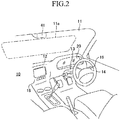
- the targeted vehicle 10 is provided with a front window 11 which is made of a translucent material.
- a portion of a front surface of an interior space of the targeted vehicle 10 is composed of a dashboard 12 located below the front window 11.
- a support portion for steering wheel 13 is provided on a right side portion of the dashboard 12.
- the support portion for steering wheel 13 projects rearward from the dashboard 12.
- a steering wheel 14 is rotatably supported by the support portion for steering wheel 13. As is well known, when rotating the steering wheel 14, steering angles of left and right front wheels 15a of the targeted vehicle 10 shown in FIG. 1 are changed.
- an operating lever for direction indicator 16 is supported by a right side surface of the support portion for steering wheel 13 so as to be rotatable in the vertical direction.
- left and right pair of direction indicators 17L, 17R are provided on a front surface of the targeted vehicle 10.
- a light fixture of the left direction indicator 17L flashes
- a light fixture of the right direction indicator 17R flashes.
- a part of the dashboard 12 is composed of an instrument panel 18.
- the display means 20 composed of a liquid crystal display is fixed to a right side portion of the instrument panel 18. As shown in FIG. 2 , the display means 20 has a substantially rectangular shape having a lateral dimension (i.e., dimension in a left and right direction) longer than its vertical dimension.
- a substantially rectangular main display area 21 is formed in a part of the display means 20. Additionally, a left-turn sign display part 28 and a right-turn sign display part 29 are provided on two parts of the display means 20. The main display area 21 is located between the left-turn sign display part 28 and the right-turn sign display part 29.
- a sub display area 22 is formed on the display means 20.
- the sub display area 22 is located directly above the main display area 21.
- a white line and leading vehicle recognition status display part 23 and a sign display unit 26 located immediately above the white line and leading vehicle recognition status display part 23 are provided on the main display area 21.
- the sign display unit 26 is provided with three display parts which are arranged in the lateral direction.
- the sign display unit 26 has a left side display part 26A, a central display part 26B, and a right side display part 26C.
- the targeted vehicle 10 is equipped with the camera control ECU 40, the sensor ECU 50, and the GPS control ECU 60. These ECUs can exchange data with each other (i.e., these ECUs can communicate with each other) via a communication and sensor systems CAN (Controller Area Network) 70.
- ECU is an abbreviation of electric control unit.
- Each of the ECUs is an electronic control circuit.
- Each of the ECUs is provided with a microcomputer including a CPU, a ROM, a RAM, an interface and the like, as main components. The CPU achieves a variety of functions described later by executing instructions stored in a memory (ROM).
- the camera control ECU 40 is connected to the wheel speed sensor 10a, the operating lever for direction indicator 16, the direction indicators 17L, 17R, the display means 20,and the camera 41.
- the wheel speed sensor 10a outputs a signal representing rotational speed of each of front wheels 15a and each of rear wheels 15b to the camera control ECU 40.
- the camera control ECU 40 makes the sub display area 22 show (display) information on the rotational speed of each of front wheels 15a and each of rear wheels 15b obtain from the wheel speed sensor 10a as vehicle speed of the targeted vehicle 10 (see FIG. 4 ).
- vehicle information on the targeted vehicle 10 is recorded on the memory of the camera control ECU 40.
- the vehicle information includes information representing that the steering wheel 14 is provided in the right side of (front surface of) the interior space of the targeted vehicle 10 (namely, the steering wheel 14 is not provided in the left side portion of front surface of the interior space).
- the camera control ECU 40 is connected to the camera 41.
- the camera 41 is fixed to the upper end portion of the inner surface of the front window 11.
- the camera 41 includes a lens and an image pickup device positioned immediately behind the lens (these are not shown).
- the image pickup device images photographing luminous flux (i.e., object image) which is a natural light reflected rearward by an object positioned in front of the targeted vehicle 10 and passing through the front window 11 and the lens.
- the data imaged by the image pickup device are repeatedly transmitted to the camera control ECU 40 from the image pickup device at every predetermined time.
- the sensor ECU 50 is connected to the radar sensor 51.
- the radar sensor 51 is a well-known millimeter wave radar sensor.
- the radar sensor 51 transmits a millimeter wave forward from the targeted vehicle 10 in accordance with instructions of the sensor ECU 50.
- the millimeter wave is reflected rearward by an object which is located in front of the targeted vehicle 10. For example, when a leading vehicle 90 runs in front of the targeted vehicle 10, the millimeter wave is reflected rearward by the leading vehicle 90. Then, the reflected wave is received by the radar sensor 51.
- the GPS control ECU 60 is connected to the GPS receiver 61.
- the GPS receiver 61 receives information on the position of the targeted vehicle 10 (hereinafter, it is referred to as "position information") by receiving a GPS signal transmitted from a GPS satellite at every predetermined time.
- the GPS receiver 61 transmits the obtained position information to the GPS control ECU 60.
- the GPS control ECU 60 time-serially records the received position information on its RAM.
- the GPS control ECU 60 When receiving the position information from the GPS receiver 61, the GPS control ECU 60 obtains a country code corresponding to the position information by applying the position information to the database that is recorded on its memory. This country code is transmitted from the GPS control ECU 60 to the camera control ECU 40. Then, the camera control ECU 40 identifies the country in which the targeted vehicle 10 is located based on the country code and the data for collating country code.
- the camera control ECU 40 determines a passing section of vehicles defined by legislation of the country in which the targeted vehicle 10 is located based on the information of the identified country and the data for determining passing section. In other words, the camera control ECU 40 determines whether vehicles have to carry out "left-hand traffic” or vehicles have to carry out "right-hand traffic”. In other words, the camera control ECU 40 determines whether the identified country is a left-hand traffic country or a right-hand traffic country.
- a road 80 on which the targeted vehicle 10 and the leading vehicle 90 are running has a left side lane 81 and a right side lane 82.
- a drive support ECU which is connected to the communication and sensor systems CAN 70 gives an instruction to the display means 20 so that the display means 20 shows a white line recognition state.
- the display means 20 shows left and right pair of white lines 23a on the white line and leading vehicle recognition status display part 23 as shown in FIG 4 .
- the central display part 26B is positioned on a straight line (not shown) extending vertically and passing through the midpoint between the left and right white lines 23a.
- the drive support ECU determines that the leading vehicle 90 is located in front of the targeted vehicle 10. Then, the drive support ECU gives an instruction to the display means 20 to show a leading vehicle recognition status. As a result, the display means 20 shows a leading vehicle image 23b (see the imaginary line in FIG. 4 ) on the white line and leading vehicle recognition status display part 23.
- ACC Adaptive Cruise Control
- the display means 20 does not show the leading vehicle image 23b on the white line and leading vehicle recognition status display part 23.
- a number of the road signs 84 (only one road sign 84 is shown in FIG. 1 ) are installed on the side of the road 80 at intervals.
- the road signs 84 represent kinds of traffic information on the area where each of the road signs 84 is installed.
- the road signs 84 include a regulation sign, an instruction sign, and a warning sign.
- the regulation sign is a sign which prohibits or designates a specific traffic method.
- the instruction sign allows a specific traffic method.
- the warning sign notifies an occupant of vehicles about danger on a road and a situation which the occupant must be careful beforehand.
- the regulation sign includes, for example, a sign representing limiting speed, a sign representing No parking, a sign representing No entry, a sign representing No overtaking, a sign representing No U-turn, and a sign representing No turn on red (No right-turn on red).
- the instruction sign includes, for example, a Parking sign and a Stopping sign.
- the warning sign includes, for example, a Railroad crossing sign, a Number of lanes reduced sign, and a Road construction sign.
- road signs 84 represent information closely related with a passing section of vehicles. In other words, some of road signs 84 represent information closely related with whether the country in which road signs 84 are installed is a left-hand traffic country or a right-hand traffic country. In other words, these road signs 84 represent traffic information that is used in only one of left-hand traffic countries and right-hand traffic countries.
- Such road signs 84 include, for example, the No overtaking sign, the No U-turn sign, and the No turn on red sign.
- such road signs 84 are referred to as "passing section-related signs.”
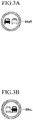
- No overtaking signs There are two kinds of No overtaking signs which are one of the passing section-related signs. Each of No overtaking signs corresponds to each of passing sections of vehicles. Namely, in a right-hand traffic country, a No overtaking sign 84aR shown in FIG. 3A is used, while in a left-hand traffic country, a No overtaking sign 84aL shown in FIG. 3B is used.
- the No overtaking sign 84aR is installed on the side of the road 80 of a right-hand traffic country, the targeted vehicle 10 running on the right side lane 82 is prohibited from overtaking the leading vehicle 90 using the left side lane 81.
- the No overtaking sign 84aL is installed on the side of the road 80 of a left-hand traffic country, the targeted vehicle 10 running on the left side lane 81 is prohibited from overtaking the leading vehicle 90 using the right side lane 82.
- No U-turn signs there are two kinds of No U-turn signs each of which corresponds to each of passing sections of vehicles. Namely, in a right-hand traffic country, a No U-turn sign 84bR shown in FIG. 3C is used, while in a left-hand traffic country, a No U-turn sign 84bL shown in FIG. 3D is used.
- the targeted vehicle 10 running on the road 80 is prohibited from moving to a road (not shown) (hereinafter, this road is referred to as an "opposite side road”.) which is positioned on a more left side than the road 80 (the left side lane 81) (in other words, this road is next to the left side lane 81 to the left) while turning left. Vehicles run on this opposite side road in an opposite direction to the targeted vehicle 10 running on the road 80.
- the targeted vehicle 10 running on the road 80 is prohibited from moving to an opposite side road which is positioned on a more right side than the road 80 (the right side lane 82) (in other words, this opposite side road is next to the right side lane 82 to the right) while turning right.
- the No turn on red sign 84cR shown in FIG. 3E is a sign that is used in a right-hand traffic country. Namely, in some of the right-hand traffic countries, even when a traffic sign installed at an intersection is "red", vehicles are allowed to turn right at the intersection as a general rule. However, at the intersection where the No turn on red sign 84cR is installed, vehicles are prohibited from turning right when the traffic signal is "red”.
- a road sign database having a large number of sign images is recorded on the memory of the camera control ECU 40.
- the group of sign images is image data corresponding to each of the road signs 84. Therefore, the group of sign images includes a sign image which corresponds to the passing section-related sign and a sign image which does not correspond to the passing section-related sign.
- a sign image corresponding to the passing section-related sign is referred to as a passing section-related sign image.
- the passing section-related sign image includes, for example, No overtaking sign images 27aR, 27aL, No U-turn sign images 27bR, 27bL, and a No turn on red sign image 27cR (a No right-turn on red sign) (see FIGS. 5 to 9 ) which will be described later.
- a pattern for right-hand traffic country and a pattern for left-hand traffic country are recorded on the memory of the camera control ECU 40.
- the pattern for right-hand traffic country defines a correspondence relationship between each of the sign images and each of the left side display part 26A, the central display part 26B, and the right side display part 26C, when the camera control ECU 40 determines that the country where the targeted vehicle 10 is located is a right-hand traffic country based on the position information received by the GPS receiver 61 (or imaged information of the camera 41 described later).
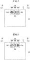
- the correspondence relationship defined by the pattern for right-hand traffic country of the present embodiment is as follows: the left side display part 26A shows the No overtaking sign image 27aR and the No U - turn sign image 27bR (passing section-related sign image), the central display part 26B shows a speed-related sign (for example, a limiting speed sign image 26X which will be described later), and the right side display part 26C shows speed-auxiliary sign (for example, a limiting speed for rainy weather sign image 26Y which will be described later).
- the pattern for right-hand traffic country defines a special rule as follows: the No turn on red sign image 27cR (passing section-related sign image) is displayed on the right side display part 26C prior to the speed-auxiliary sign.
- a pattern for left-hand traffic country defines a correspondence relationship between each of the sign images and each of the left side display part 26A, the central display part 26B, and the right side display part 26C, when the camera control ECU 40 determines that the country where the targeted vehicle 10 is located is the left-hand traffic country.
- the left side display part 26A shows the speed-auxiliary sign (for example, the limiting speed for rainy weather sign image 26Y)
- the central display part 26B shows the speed-related sign (for example, the limiting speed sign image 26X)
- the right side display part 26C shows the No overtaking sign image 27aL and the No U - turn sign image27bL (passing section-related sign image).
- the camera control ECU 40 determines whether or not picked up image data, which is received from the camera 41, includes an image coincident with the sign image in the road sign database by performing pattern matching using the road sign database and the picked up image data.
- the camera control ECU 40 makes the sign display unit 26 show the No overtaking sign image 27aR for a certain period of time.
- the camera control ECU 40 When the road sign 84 imaged by the camera 41 is the No overtaking sign 84aR, the camera control ECU 40 usually determines that a country where the targeted vehicle 10 is running is the right-hand traffic country.
- the camera control ECU 40 makes the left side display part 26A of the sign display unit 26 show the No overtaking sign image 27aR for a certain period of time based on the pattern for right-hand traffic country.
- the targeted vehicle 10 usually runs on the right side lane 82.
- the targeted vehicle 10 overtakes the leading vehicle 90 located on the right side lane 82, the targeted vehicle 10 overtakes the leading vehicle 90 after moving to the left side lane 81. Therefore, at this time (when operating the targeted vehicle 10 to overtake) the driver of the targeted vehicle 10 is highly likely to look at a more left side than the front.
- a vehicle control ECU (not shown) makes the left-turn sign display part 28 flash. As a result, consciousness of the driver is turned to the left by the flashing left-turn sign display part 28.
- the camera control ECU 40 makes the sign display unit 26 show the No overtaking sign image 27aL for a certain period of time.
- the camera control ECU 40 When the road sign 84 imaged by the camera 41 is the No overtaking sign 84aL, the camera control ECU 40 usually determines that the country where the targeted vehicle 10 is running is a left-hand traffic country.
- the camera control ECU 40 makes the right side display part 26C of the sign display unit 26 show the No overtaking sign image 27aL for a certain period of time based on the pattern for left-hand traffic country.
- the targeted vehicle 10 usually runs on the left side lane 81.
- the targeted vehicle 10 overtakes the leading vehicle 90 located on the left side lane 81, the targeted vehicle 10 overtakes the leading vehicle 90 after moving to the right side lane 82. Therefore, when operating the targeted vehicle 10 to overtake, the driver of the targeted vehicle 10 is highly likely to look at a more right side than the front.
- the vehicle control ECU makes the right-turn sign display part 29 flash. As a result, consciousness of the driver is turned to the right by the flashing right-turn sign display part 29.
- the camera control ECU 40 determines whether or not the targeted vehicle 10is trying to overtake.
- the camera control ECU 40 calls the driver's attention by flashing one of the No overtaking sign image 27aR and the No overtaking sign image 27aL which is displayed on the sign display unit 26.
- the camera control ECU 40 may be configured to show one of the No overtaking sign image 27aR and the No overtaking sign image 27aL in another manner to call the driver's attention rather than flashing one of the No overtaking sign image 27aR and the No overtaking sign image 27aL.
- the camera control ECU 40 makes the sign display unit 26 show the No U-turn sign image 27bR for a certain period of time.
- the camera control ECU 40 When the road sign 84 imaged by the camera 41 is the No U-turn sign 84bR, the camera control ECU 40 usually determines that the country where the targeted vehicle 10 is running is a right-hand traffic country.
- the camera control ECU 40 makes the left side display part 26A of the sign display unit 26 show the No U-turn sign image 27bR for a certain period of time based on the pattern for right-hand traffic country.
- the targeted vehicle 10 usually runs on the right side lane 82.
- the driver operates the targeted vehicle 10 to turn left so as to traverse the left side lane 81, and thereby the targeted vehicle 10 moves to the opposite side road positioned on a more left side than the road 80. Therefore, at this time the driver of the targeted vehicle 10 looks at a more left side than the front.
- the vehicle control ECU makes the left-turn sign display part 28 flash. As a result, consciousness of the driver is turned to the left by the flashing left-turn sign display part 28.
- the camera control ECU 40 makes the sign display unit 26 show the No U-turn sign image 27bL for a certain period of time.
- the camera control ECU 40 When the road sign 84 imaged by the camera 41 is the No U-turn sign 84bL, the camera control ECU 40 usually determines that the country where the targeted vehicle 10 is running is a left-hand traffic country.
- the camera control ECU 40 makes the right side display part 26C of the sign display unit 26 show the No U-turn sign image 27bL for a certain period of time based on the pattern for left-hand traffic country.
- the targeted vehicle 10 usually runs on the left side lane 81.
- the driver operates the targeted vehicle 10 to turn right so as to traverse the right side lane 82, and thereby the targeted vehicle 10 moves to the opposite side road positioned on a more right side than the road 80. Therefore, at this time the driver of the targeted vehicle 10 looks at a more right side than the front.
- the vehicle control ECU makes the right-turn sign display part 29 flash. As a result, consciousness of the driver is turned to the right by the flashing right-turn sign display part 29.
- the camera control ECU 40 makes the sign display unit 26 show the No turn on red sign image 27cR for a certain period of time.
- the camera control ECU 40 When the road sign 84 imaged by the camera 41 is the No turn on red sign 84cR, the camera control ECU 40 usually determines that the country where the targeted vehicle 10 is running is a right-hand traffic country.
- the camera control ECU 40 makes the right side display part 26C of the sign display unit 26 show the No turn on red sign image 27cR for a certain period of time based on the pattern for right-hand traffic country.
- the targeted vehicle 10 When the targeted vehicle 10 turns right at an intersection where the No turn on red sign 84cR is installed, in the vicinity of the intersection the targeted vehicle 10 runs on the right side lane 82.
- the driver of the targeted vehicle 10 is highly likely to look at a more right side than the front to prepare a turn-right operation when the traffic signal is changed to "green".
- the vehicle control ECU makes the right-turn sign display part 29 flash. As a result, consciousness of the driver is turned to the right by the flashing right-turn sign display part 29.
- the camera control ECU 40 selectively makes one of the left side display part 26A and the right side display part 26C shows the passing section-related sign image based on the passing section defined by legislation of the country where the targeted vehicle 10 is currently running.
- the targeted vehicle 10 moves between a left-hand traffic country (for example, the United Kingdom) and a right-hand traffic country (for example, France), the driver is unlikely to get an odd feeling when looking at the sign display unit 26.
- a left-hand traffic country for example, the United Kingdom
- a right-hand traffic country for example, France
- the camera control ECU 40 selects a sign image corresponding to this road sign 84 from the road sign database and makes the sign display unit 26 shows this sign image.
- This type of sign images include, for example, the limiting speed sign image 26X and the limiting speed for rainy weather sign image 26Y shown in FIGS. 5 to 9 .
- Road signs 84 corresponding to these sign images are used in left-hand traffic countries and right-hand traffic countries, and represent the same content in any countries. In other words, these sign images are highly unlikely to provide an odd feeling to a driver who watches the sign display unit 26 even when these sign images are displayed on any one of the left side display part 26A, the central display part 26B, and the right side display part 26C.
- the pattern for right-hand traffic country defines the correspondence relationship.
- the central display part 26B shows the speed-related sign (for example, the limiting speed sign image 26X) and the right side display part 26C shows the speed-auxiliary sign (for example, the limiting speed for rainy weather sign image 26Y).
- the pattern for left-hand traffic country defines the correspondence relationship.
- the left side display part 26A shows the speed-auxiliary sign (for example, the limiting speed for rainy weather sign image 26Y) and the central display part 26B shows the speed-related sign (for example, the limiting speed sign image 26X).
- the camera control ECU 40 makes any one of the left side display part 26A, the central display part 26B, and the right side display part 26C show these sign images for a certain period of time in accordance with the pattern for right-hand traffic country or the pattern for left-hand traffic country.
- the camera control ECU 40 refers to a database for relationship between sign and passing section recorded on the memory of the camera control ECU 40 when the road sign 84 imaged by the camera 41 is the passing section-related sign (i.e., when the road sign 84 is coincident with the passing section-related sign image in the road sign database by performing pattern matching).
- This database for relationship between sign and passing section represents whether the passing section-related sign imaged by the camera 41 (and the passing section-related sign image corresponding to this passing section-related sign) is used in a right-hand traffic country or a left-hand traffic country.
- the camera control ECU 40 determines whether this passing section-related sign (and the passing section-related sign image corresponding to this passing section-related sign) is used in a right-hand traffic country or a left-hand traffic country based on the database for relationship between sign and passing section.
- the camera control ECU 40 may refer to the database for relationship between sign and passing section only when the camera control ECU 40 selects passing section-related sign images all of which correspond to the same passing section from the road sign database equal to or more than a predetermined times (multiple times).
- the camera control ECU 40 cannot perform pattern matching using the road sign 84 imaged by the camera 41 and the road sign database with high accuracy. In other words, there is a fear that the camera control ECU 40 selects a sign image which does not correspond to the road sign 84 imaged by the camera 41 from the road sign database.
- the camera control ECU 40 selects passing section-related sign images all of which correspond to the same passing section from the road sign database equal to or more than the predetermined times, it can be assumed that the pattern matching is performed with high accuracy.
- to select the predetermined times means to include not only “to select the same passing section-related sign image (for example, the No overtaking sign image 27aR) the predetermined times” but also "to select passing section-related sign images different from each other (for example, the No overtaking sign image 27aR and the No U-turn sign image 27bR) the predetermined times (which is total number of times)".
- the camera control ECU 40 can determine whether the country where the targeted vehicle 10 is currently located is a right-hand traffic country or a left-hand traffic country based on the picked up image data imaged by the camera 41 instead of the above-mentioned position information which the GPS receiver 61 receives from the GPS satellite.
- the GPS receiver 61 receives the position information, it is preferable to determine the passing section by using the position information instead of the picked up image data.
- the camera control ECU 40 When a battery (not shown) of the targeted vehicle 10 is in a state where the battery can supply electricity to the wheel speed sensor 10a, the direction indicators 17L, 17R, the display means 20, the drive support ECU, the camera control ECU 40, the camera 41, the sensor ECU 50, the radar sensor 51, the GPS control ECU 60, and the GPS receiver 61 and an engine of the targeted vehicle 10 is started by the operation of the ignition key (not shown), the camera control ECU 40 repeatedly carries out a routine shown in the flowchart of FIG. 10 .
- the camera control ECU 40 determines whether or not the data received from the GPS control ECU 60 (the GPS receiver 61) includes the country code.
- the camera control ECU 40 proceeds to step 1002, and identify the country in which the targeted vehicle 10 is located based on the country code received from the GPS receiver 61 and the data for collating country code recorded on the memory of the camera control ECU 40.
- the camera control ECU 40 proceeds to step 1003, and the camera control ECU 40 determines the passing section of the country where the targeted vehicle 10 is located based on information on the country identified at step 1002 and the data for determining passing section recorded on the memory of the camera control ECU 40. In other words, the camera control ECU 40 determines whether the country is a right-hand traffic country or a left-hand traffic country.
- the camera control ECU 40 determines that "this country is a left-hand traffic country”.
- the camera control ECU 40 determines that "this country is a right-hand traffic country”.
- the camera control ECU 40 proceeds to step 1004, and determines whether or not the picked up image data imaged by the camera 41 includes the passing section-related sign. In other words, the camera control ECU 40 determines whether or not the road sign 84 imaged by the camera 41 is coincident with the passing section-related sign image in the road sign database by performing pattern matching.
- step 1004 the camera control ECU 40 proceeds to step 1005, and determines whether the passing section-related sign image corresponding to the road sign 84 imaged by the camera 41 is for a right-hand traffic country or for a left-hand traffic country with reference to the database for relationship between sign and passing section.
- the camera control ECU 40 When determining that "the passing section-related sign image (the road sign 84) is for a right-hand traffic country" at step 1005, the camera control ECU 40 proceeds to step 1006. Then, the camera control ECU 40 adds "1" to the sum (the total value) of the right-hand traffic country count number, and set the sum of the left-hand traffic country count number to"0".
- the camera control ECU 40 proceeds to step 1007. Then, the camera control ECU 40 adds "1" to the sum of the left-hand traffic country count number, and set the sum of the right-hand traffic country count number to "0".
- the camera control ECU 40 that has completed the process of steps 1006 or 1007 proceeds to step 1008, and determines whether or not the sum of the left-hand traffic country count number or the sum of the right-hand traffic country count number is equal to or more than the predetermined times.
- the camera control ECU 40 which has determined that "step 1008 is Yes" proceeds to step 1009, and determines the passing section of the country where the targeted vehicle 10 is running using determination result of step 1005.
- the camera control ECU 40 determines that "the country where the targeted vehicle 10 is running is a right-hand traffic country”.
- the camera control ECU 40 that has completed the process of steps 1003 or 1009 proceeds to step 1011, and determines whether or not the country where the targeted vehicle 10 is located is a right-hand traffic country by using the determination result of steps 1003 or 1009.
- the camera control ECU 40 determines that this country is a right-hand traffic country and proceeds to step 1012. Then, the camera control ECU 40 sets a right-hand traffic flag to "1" at step 1012.
- the camera control ECU 40 determines that this country is a left-hand traffic country at step 1011 and proceeds to step 1013. Then, the camera control ECU 40 sets the right-hand traffic flag to "0" at step 1013.
- step 1004 when determining that "step 1004 is No" (namely, when determining that the data received from the GPS control ECU 60 does not include the country code and the picked up image data imaged by the camera 41 does not include the passing section-related sign, the camera control ECU 40 proceeds to step 1010.
- step 1008 when determining that "step 1008 is No" (namely, that the sum of the left-hand traffic country count number or the sum of the right-hand traffic country count number is less than the predetermined times), the camera control ECU 40 proceeds to step 1010.
- the camera control ECU 40 determines whether the steering wheel 14 is provided on the right side portion of the interior space (the dashboard 12) or on the left side portion of the interior space (the dashboard 12) based on the vehicle information recorded on its memory at step 1010. Then, when determining that the steering wheel 14 is provided on the right side portion of the interior space (the dashboard 12), the camera control ECU 40 assumes that "the country where the targeted vehicle 10 is located is a left-hand traffic country". On the other hand, when determining that the steering wheel 14 is provided on the left side portion of the interior space (the dashboard 12), the camera control ECU 40 assumes that "the country where the targeted vehicle 10 is located is a right-hand traffic country".
- the camera control ECU 40 determines that "the country where the targeted vehicle 10 is located is a left-hand traffic country" at step 1010 and proceeds to step 1013.
- the camera control ECU 40 proceeds to step 1012.
- the camera control ECU 40 that has completed the process of steps 1012 or 1013 temporarily ends the routine.
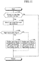
- the camera control ECU 40 When the ignition key is operated, the camera control ECU 40 further repeatedly carries out the routine shown in the flowchart of FIG 11 .
- the camera control ECU 40 performs pattern matching using the road sign database recorded on the memory of the camera control ECU 40 and the picked up image data which is transmitted from the camera 41 to the camera control ECU 40 at step 1101.
- the camera control ECU 40 determines whether or not the picked up image data includes an image corresponding to the sign image in the road sign database.
- step 1101 the camera control ECU 40 proceeds to step 1102 and selects a sign image which is coincident with the picked up image data from the road sign database.
- the picked up image data includes a road sign 84 representing "limiting speed is 120km/h”
- the camera control ECU 40 selects the limiting speed sign image 26X from the road sign database.
- the camera control ECU 40 selects the limiting speed for rainy weather sign image 26Y from the road sign database.
- the camera control ECU 40 selects the No overtaking sign image 27aR or the No overtaking sign image 27aL from the road sign database.
- the camera control ECU 40 selects the No U-turn sign image 27bR or the No U-turn sign image 27bLfrom the road sign database.
- the camera control ECU 40 selects the No turn on red sign image 27cR from the road sign database.
- the camera control ECU 40 which has completed the process of step 1102 proceeds to step 1103, and determines whether or not the right-hand traffic flag is "1".
- step 1103 the camera control ECU 40 proceeds to step 1104. Then, based on the pattern for right-hand traffic country, the camera control ECU 40 makes any one of the left side display part 26A, the central display part 26B, and the right side display part 26C show the sign image selected at step 1102 for a certain period of time.
- step 1103 the camera control ECU 40 proceeds to step 1105. Then, based on the pattern for left-hand traffic country, the camera control ECU 40 makes any one of the left side display part 26A, the central display part 26B, and the right side display part 26C show the sign image selected at step 1102 for a certain period of time.
- the camera control ECU 40 that has completed the process of steps 1004 and 1005 temporarily ends the routine.
- the position of the main display area 21 and/or the position of the sub display area 22 in the display means 20 can be changed from the position (s) of the above embodiment.
- the main display area 21 can be positioned on a more left side than the left-turn sign display part 28 or on a more right side than the right-turn sign display part 29.
- the position of the sign display unit 26 in the main display area 21 can be changed from the position in the above embodiment.
- the sign display unit 26 may include two display parts arranged in a lateral direction or equal to or more than four display parts arranged in a lateral direction.
- the sign display unit 26 is provided with five display parts 26A, 26B, 26C, 26D, and 26E which are arranged in a lateral direction.
- the camera control ECU 40 also does not make the display part 26C, which is located at the center of the sign display unit 26, show the passing section-related sign image.
- the passing section-related sign image is selectively displayed on the left side display parts 26A, 26B which are located on a more left side than the central display part 26C of the sign display unit 26 or on the right side display parts 26D, 26E which are located on a more right side than the central display part 26C of the sign display unit 26. Therefore, for example, as shown in FIG. 12 , the camera control ECU 40 makes the second display part 26B from the left show the No overtaking sign image 27aR. It should be noted that, in this case, the No overtaking sign image 27aR may be displayed on the left end display part 26A. Similarly, for example, the camera control ECU 40 makes the second display part 26D from the right or the right end display part 26E show the No overtaking sign image 27aL.
- two sign display units 26-1, 26-2 spaced from each other in a lateral direction are provided in the main display area 21.
- the camera control ECU 40 makes any one of display parts 26A, 26B, 26C of the right side sign display unit 26-2 (right side display part) show the No overtaking sign image 27aL.
- the camera control ECU 40 makes any one of display parts 26A, 26B, 26C of the left side sign display unit 26-1 (left side display part) show the No overtaking sign image 27aR.
- a left-hand traffic country in which the targeted vehicle 10 is located, may have legislation which allows vehicles to turn left at an intersection as a general rule when a traffic signal installed at this intersection is "red".
- a No turn on red sign (a No left-turn on red sign), which exceptionally prohibits vehicles from turning left at an intersection in the case where a traffic signal is "red”
- a sign image corresponding to this No turn on red sign may be displayed on the left side display part of each of the above sign display units.
- the targeted vehicle 10 may be provided with means which can receive information from a satellite of the Global Navigation Satellite System (GNSS) other than GPS (e.g., Galileo) and can exchange data (can communicate) with the camera control ECU 40 and the sensor ECU 50.
- GNSS Global Navigation Satellite System
- Galileo Global Navigation Satellite System
- the targeted vehicle 10 may be provided with a vehicle-mounted device capable of wireless communicating with a roadside device installed along a road.
- the roadside device sends a variety of traffic information.
- the content of this information is the same as the traffic information represented by each of the road signs 84.
- the targeted vehicle 10 configured in such a manner can perform pattern matching using the traffic information from the roadside device and the road sign database and can make the display means 20 show the sign images selected from the road sign database.
- Display means for displaying, for example, the vehicle speed of the targeted vehicle 10 and/or sign image may be installed to a part of the targeted vehicle 10 other than the instrument panel 18.
- a windscreen 11 a may be used as the display means.
- the windscreen 11 a forms a part of the front window 11 and can project an image generated by a head-up display unit (not shown).
- a sign display unit (which has a plurality of display parts arranged in a lateral direction) corresponding to the sign display unit 26 (26-1, 26-2) is formed on the windscreen 11 a.
- each of the passing section-related sign images is selectively displayed on a right side display part or a left side display part of this sign display unit.
- a display device for vehicle (100), which is installed to a targeted vehicle (10), comprises display position changing means (40).
- the display position changing means selectively makes one of a left side display part, which is at least one of the plurality of display parts and is position on a more left side than the center of the display means in a lateral direction, and a right side display part, which is at least one of the plurality of display parts and is position on a more right side than the center, show a passing section-related sign image (27aR, 27aL, 27bR, 27bL, 27cR) that is the sign image corresponding to the passing section-related sign based on determination result by the passing section determination means, when the road sign identified based on the obtained sign information is the passing section-related sign (steps 1004, 1105).
Landscapes
- Engineering & Computer Science (AREA)
- Mechanical Engineering (AREA)
- Transportation (AREA)
- Combustion & Propulsion (AREA)
- Chemical & Material Sciences (AREA)
- Physics & Mathematics (AREA)
- General Physics & Mathematics (AREA)
- Remote Sensing (AREA)
- Radar, Positioning & Navigation (AREA)
- Automation & Control Theory (AREA)
- Computer Hardware Design (AREA)
- Theoretical Computer Science (AREA)
- Life Sciences & Earth Sciences (AREA)
- Atmospheric Sciences (AREA)
- Traffic Control Systems (AREA)
- Instrument Panels (AREA)
Abstract
Description
- The present invention relates to a display device for vehicle which is installed to a vehicle and has a display means capable of showing images corresponding to a plurality of road signs, which include a limiting speed sign, a No parking sign, a No overtaking sign, and the like, such that the images are arranged in a lateral direction.
-
Japanese Unexamined Patent Application Publication No. 2012-30611 - The display means shows, for example, vehicle speed and outside air temperature, and the like.
- In addition, the vehicle is equipped with a vehicle-mounted device which can wirelessly communicate with a roadside device installed along a road.
- The roadside device sends a variety of traffic information on an area where the roadside device is installed to the vehicle-mounted device. The traffic information received by the vehicle-mounted device is displayed on a sign display unit, which is an area corresponding to a part of the display means, as a plurality of sign images representing road signs.
- The sign display unit has display parts which are arranged in a lateral direction. When the vehicle-mounted device receives a plurality of species of traffic information, the display parts display a sign image respectively.
- The traffic information represented by each of the sign images includes, for example, limiting speed of a vehicle, lane regulation, and No overtaking (No passing), and the like.
- Accordingly, an occupant of the vehicle can recognize not only vehicle speed, outside air temperature and the like but also a variety of traffic information represented by the sign images by watching the display means.
- Additionally, in the vehicle of the
Japanese Unexamined Patent Application Publication No. 2012-30611 - For example, a No overtaking sign image is displayed on the right display part of the sign display unit.
- When a vehicle runs on a road of a country, for example Japan, in which vehicles have to keep to the left, the vehicle overtakes while temporarily moving to a lane (traffic lane) next to a lane on which this vehicle is currently running to the right. Therefore, a driver of the vehicle is highly likely to look at a more right side than the front when the driver operates the vehicle to overtake.
- Therefore, if the No overtaking sign image is displayed on the right display part of the sign display unit, driver is not likely to get an odd feeling (i.e., the driver feels something is wrong) when the driver watches the No overtaking sign image displayed on the sign display unit.
- By the way, there is a possibility that the vehicle runs on both a road of a country having a type of passing section (transit division, distinction of passage) and a road of another country having another type of passing section. In other words, there is a possibility that the vehicle of the
Japanese Unexamined Patent Application Publication No. 2012-30611 - When the vehicle of the
Japanese Unexamined Patent Application Publication No. 2012-30611 - However, in the vehicle of the
Japanese Unexamined Patent Application Publication No. 2012-30611 - Therefore, even when the vehicle of the
Japanese Unexamined Patent Application Publication No. 2012-30611 - The present invention has been made to cope with the above problems, and has an object to provide a display device for vehicle which can make a risk of providing an odd feeling to a driver small, when a passing section-related sign image, which is a sign image corresponding to a road sign related with a passing section, is displayed on the display means in the case where the vehicle runs on both a road of a country having a type of passing section and a road of another country having another type of passing section.
- In order to achieve the object, a display device for vehicle (100) of the present invention, which is installed to a targeted vehicle (10) comprises:
- passing section determination means (40) determining whether legislation, which defines a passing section of vehicles in a country having a road (80) on which the targeted vehicle is running, lays down that vehicles have to keep to the left or that vehicles have to keep to the right (
steps - display means (20) including a plurality of display parts (26A, 26B, 26C, 26D, 26E) arranged in a lateral direction, each of the display parts capable of showing a sign image (26X, 26Y, 27aR, 27aL, 27bR, 27bL, 27cR) corresponding to each of a plurality of road signs (84) including a passing section-related sign (84aL, 84aR, 84bL, 84bR, 84cR) that represents traffic information related with the passing section;
- sign information obtaining means (41) obtaining sign information, the sign information identifying the road sign with which a driver of the targeted vehicle has to comply (step 1101); and
- display position changing means (40) selectively makes one of a left side display part, which is at least one of the plurality of display parts and is position on a more left side than the center of the display means in a lateral direction, and a right side display part, which is at least one of the plurality of display parts and is position on a more right side than the center, show a passing section-related sign image (27aR, 27aL, 27bR, 27bL, 27cR) that is the sign image corresponding to the passing section-related sign based on determination result by the passing section determination means, when the road sign identified based on the obtained sign information is the passing section-related sign (steps 1004, 1105).
- Noted that, the "passing section-related sign" is a road sign representing traffic information which is closely related with a passing section of vehicles (in other words, the traffic information is closely related with whether vehicles have to keep to the left or the right). In other words, the "passing section-related sign" is a road sign that is used in only one of a country where the vehicles have to keep to the left and a country where the vehicles have to keep to the right.
- The passing section-related sign includes, for example, a No overtaking sign, a No U-turn sign, and a No turn on red sign (a No right-turn on red sign or a No left-turn on red sign).
- Noted that, in the following description of this specification, the country where vehicles have to keep to the left is referred to as a "left-hand traffic country", and the country where vehicles have to keep to the right is referred to as a "right-hand traffic country".
- The targeted vehicle is likely to run on roads of a variety of countries around the world. In other words, the targeted vehicle is likely to run on a road of a left-hand traffic country and on a road of a right-hand traffic country.
- For example, in the case where the targeted vehicle to which the display device for vehicle is installed runs on a road of a left-hand traffic country, when the targeted vehicle is prohibited from overtaking on the road on which this targeted vehicle is currently running, a passing section-related sign image representing No overtaking is displayed on the right display part. In this case, the targeted vehicle overtakes while moving to a lane next to a lane on which the targeted vehicle is currently running to the right. Therefore, a driver of the targeted vehicle is highly likely to look at a more right side than the front when the driver operates the vehicle to overtake. Therefore, when the driver watches the passing section-related sign image, a fear of providing an odd feeling to the driver becomes small by displaying the passing section-related sign image representing No overtaking on the right display part.
- On the other hand, in the case where the targeted vehicle runs on a road of a right-hand traffic country, when the targeted vehicle is prohibited from overtaking on the road on which this targeted vehicle is currently running, a passing section-related sign image representing No overtaking is displayed on the left display part. In this case, the targeted vehicle overtakes while moving to a lane next to a lane on which the targeted vehicle is currently running to the left. Therefore, the driver of the targeted vehicle is highly likely to look at a more left side than the front when the driver operates the vehicle to overtake. Therefore, when the driver watches the passing section-related sign image, a fear that the driver gets an odd feeling becomes small by displaying the passing section-related sign image representing No overtaking on the left display part.
- According to the present invention, both in a left-hand traffic country and in a right-hand traffic country, the fear of providing an odd feeling to the driver can be small when the passing section-related sign image is displayed on the display means.
- In one of aspects of the present invention, the display position changing means is configured so that in the case where the road sign identified based on the obtained sign information is a No overtaking sign (84aR, 84aL) which is one of the passing section-related signs, the right side display part shows the sign image (27aL) corresponding to the No overtaking sign when the passing section determination means determines that vehicles have to keep to the left in compliance with the legislation, whereas the left side display part shows the sign image (27aR) corresponding to the No overtaking sign when the passing section determination means determines that vehicles have to keep to the right in compliance with the legislation.
- In one of aspects of the present invention, the display position changing means is configured so that in the case where the road sign identified based on the obtained sign information is a No U-turn sign (84bR, 84bL) which is one of the passing section-related signs, the right side display part shows the sign image (27bL) corresponding to the No U-turn sign when the passing section determination means determines that vehicles have to keep to the left in compliance with the legislation, whereas the left side display part shows the sign image (27bR) corresponding to the No U-turn sign when the passing section determination means determines that vehicles have to keep to the right in compliance with the legislation.
- In one of aspects of the present invention, the display position changing means is configured so that in the case where the road sign identified based on the obtained sign information is either a No right-turn on red sign (84cR) or a No left-turn on red sign which is one of the passing section-related signs, the left side display part shows the sign image corresponding to the No left-turn on red sign when the passing section determination means determines that vehicles have to keep to the left in compliance with the legislation, whereas the right side display part shows the sign image (27cR) corresponding to the No right-turn on red sign when the passing section determination means determines that the vehicles have to keep to the right in compliance with the legislation.
- If the present invention is carried out as these embodiments, both in a left-hand traffic country and in a right-hand traffic country, a fear of providing an odd feeling to the driver can be small when the sign images, which correspond to the No overtaking sign, the No U-turn sign, the No right-turn on red sign, and the No left-turn on red sign, are displayed on the display means.
- In one of aspects of the present invention, the display means comprises:
- a left-turn sign display part (28) showing that a left direction indicator (17L) installed to the targeted vehicle is operated; and
- a right-turn sign display part (29) showing that a right direction indicator (17R) installed to the targeted vehicle is operated, the right-turn sign display part positioned on a more right side than the left-turn sign display part.
- Furthermore, the plurality of display parts (26A, 26B, 26C, 26D, 26E) are disposed between the left-turn sign display part and the right-turn sign display part.
- For example, in the case where the targeted vehicle runs on a road of a left-hand traffic country, when the driver operates the targeted vehicle to overtakes, the right direction indicator is operated by the driver. Then, the right-turn sign display part shows that the right direction indicator is operated.
Therefore, consciousness of the driver is turned to the right. - In this case, if the No overtaking sign image is displayed on the left display part of the display means (i.e., a display part which is near a portion on which the left-turn sign display part is displayed), a fear that the driver whose consciousness is turned to the right gets an odd feeling is large.
- However, the display means of the present invention shows the No overtaking sign image on the right display part (i.e., a display part which is near a portion on which the right-turn sign display part is displayed). Therefore, a fear that the driver whose consciousness is turned to the right gets an odd feeling is small.
- In the above description, references used in the following descriptions regarding embodiments are added with parentheses to the elements of the present invention, in order to understand the invention. However, those references should not be used to limit the scope of the present invention. Other objects, other features, and accompanying advantages of the present invention are easily understood from the description of embodiments of the present invention to be given referring to the following drawings.
-
-
FIG. 1 is a view showing a targeted vehicle having a display device for vehicle according to an embodiment of the present invention, a leading vehicle, and a road on which these vehicles run. -
FIG. 2 is a view showing an interior space of the targeted vehicle and a front window of the targeted vehicle. -
FIG. 3A is a view showing a No overtaking sign used in a right-hand traffic country. -
FIG. 3B is a view showing a No overtaking sign used in a left-hand traffic country. -
FIG. 3C is a view showing a No U - turn sign used in a right-hand traffic country. -
FIG. 3D is a view showing a No U - turn sign used in a left-hand traffic country. -
FIG. 3E is a view showing a No turn on red sign. -
FIG. 4 is a schematic diagram showing a display means. -
FIG. 5 is a view showing a main display area of the display means which shows a No overtaking sign image when the targeted vehicle runs on a road of a right-hand traffic country. -
FIG. 6 is a view showing the main display area which shows a No overtaking sign image when the targeted vehicle runs on a road in a left-hand traffic country. -
FIG. 7 is a view showing the main display area which shows a No U - turn sign image when the targeted vehicle runs on a road in a right-hand traffic country. -
FIG. 8 is a view showing the main display area which shows a No U - turn sign image when the targeted vehicle runs on a road in a left-hand traffic country. -
FIG. 9 is a view showing the main display area which shows a No turn on red sign image when the targeted vehicle runs on a road in a right-hand traffic country. -
FIG. 10 is a flowchart showing a process which is carried out by a camera control ECU to determine a passing section. -
FIG. 11 is a flowchart showing a process which is carried out by the camera control ECU to display sign images. -
FIG. 12 is a schematic diagram showing a display means according to a modified embodiment of the present invention. -
FIG. 13 is a schematic diagram showing a display means according to another modified embodiment of the present invention. - A display device for vehicle according to an embodiment of the present invention will be described hereinafter with reference to the accompanying drawings.
- As shown in
FIG. 1 , the display device forvehicle 100 according to the embodiment of the present invention is installed to a vehicle 10 (hereinafter, it is referred to as a targeted vehicle 10). - The display device for
vehicle 100 is provided with awheel speed sensor 10a, display means 20, acamera control ECU 40, acamera 41, asensor ECU 50, aradar sensor 51, aGPS control ECU 60, and aGPS receiver 61, all of which will be described later. - As shown in
FIGS. 1 and2 , the targetedvehicle 10 is provided with afront window 11 which is made of a translucent material. - Furthermore, as shown in
FIG. 2 , a portion of a front surface of an interior space of the targetedvehicle 10 is composed of adashboard 12 located below thefront window 11. A support portion forsteering wheel 13 is provided on a right side portion of thedashboard 12. The support portion forsteering wheel 13 projects rearward from thedashboard 12. Asteering wheel 14 is rotatably supported by the support portion forsteering wheel 13. As is well known, when rotating thesteering wheel 14, steering angles of left and rightfront wheels 15a of the targetedvehicle 10 shown inFIG. 1 are changed. - Furthermore, an operating lever for
direction indicator 16 is supported by a right side surface of the support portion forsteering wheel 13 so as to be rotatable in the vertical direction. As shown inFIG. 1 , left and right pair ofdirection indicators vehicle 10. As is well known, when rotating the operating lever fordirection indicator 16 upward from the initial position, a light fixture of theleft direction indicator 17L flashes, and when rotating the operating lever fordirection indicator 16 downward from the initial position, a light fixture of theright direction indicator 17R flashes. - Additionally, a part of the
dashboard 12 is composed of aninstrument panel 18. The display means 20 composed of a liquid crystal display is fixed to a right side portion of theinstrument panel 18. As shown inFIG. 2 , the display means 20 has a substantially rectangular shape having a lateral dimension (i.e., dimension in a left and right direction) longer than its vertical dimension. - As shown in
FIGS. 4 to 9 , a substantially rectangularmain display area 21 is formed in a part of the display means 20. Additionally, a left-turnsign display part 28 and a right-turnsign display part 29 are provided on two parts of the display means 20. Themain display area 21 is located between the left-turnsign display part 28 and the right-turnsign display part 29. - Furthermore, as shown in
FIG. 4 , asub display area 22 is formed on the display means 20. Thesub display area 22 is located directly above themain display area 21. - A white line and leading vehicle recognition
status display part 23 and asign display unit 26 located immediately above the white line and leading vehicle recognitionstatus display part 23 are provided on themain display area 21. - The
sign display unit 26 is provided with three display parts which are arranged in the lateral direction. In other words, thesign display unit 26 has a leftside display part 26A, acentral display part 26B, and a rightside display part 26C. - It should be noted that types of images showed by the line and leading vehicle recognition
status display part 23 and thesign display unit 26 will be described later. - As shown in
FIG. 1 , the targetedvehicle 10 is equipped with thecamera control ECU 40, thesensor ECU 50, and theGPS control ECU 60. These ECUs can exchange data with each other (i.e., these ECUs can communicate with each other) via a communication and sensor systems CAN (Controller Area Network) 70. Noted that ECU is an abbreviation of electric control unit. Each of the ECUs is an electronic control circuit. Each of the ECUs is provided with a microcomputer including a CPU, a ROM, a RAM, an interface and the like, as main components. The CPU achieves a variety of functions described later by executing instructions stored in a memory (ROM). - As shown in
FIG. 1 , thecamera control ECU 40 is connected to thewheel speed sensor 10a, the operating lever fordirection indicator 16, thedirection indicators camera 41. - The
wheel speed sensor 10a outputs a signal representing rotational speed of each offront wheels 15a and each ofrear wheels 15b to thecamera control ECU 40. Thecamera control ECU 40 makes thesub display area 22 show (display) information on the rotational speed of each offront wheels 15a and each ofrear wheels 15b obtain from thewheel speed sensor 10a as vehicle speed of the targeted vehicle 10 (seeFIG. 4 ). - Additionally, vehicle information on the targeted
vehicle 10 is recorded on the memory of thecamera control ECU 40. The vehicle information includes information representing that thesteering wheel 14 is provided in the right side of (front surface of) the interior space of the targeted vehicle 10 (namely, thesteering wheel 14 is not provided in the left side portion of front surface of the interior space). - As shown in
FIG. 1 , thecamera control ECU 40 is connected to thecamera 41. As shown inFIG. 2 , thecamera 41 is fixed to the upper end portion of the inner surface of thefront window 11. - The
camera 41 includes a lens and an image pickup device positioned immediately behind the lens (these are not shown). The image pickup device images photographing luminous flux (i.e., object image) which is a natural light reflected rearward by an object positioned in front of the targetedvehicle 10 and passing through thefront window 11 and the lens. The data imaged by the image pickup device are repeatedly transmitted to thecamera control ECU 40 from the image pickup device at every predetermined time. - "Data for collating country code" and "data for determining passing section" are recorded on the memory of the
camera control ECU 40. - As shown in
FIG. 1 , thesensor ECU 50 is connected to theradar sensor 51. Theradar sensor 51 is a well-known millimeter wave radar sensor. Theradar sensor 51 transmits a millimeter wave forward from the targetedvehicle 10 in accordance with instructions of thesensor ECU 50. The millimeter wave is reflected rearward by an object which is located in front of the targetedvehicle 10. For example, when a leadingvehicle 90 runs in front of the targetedvehicle 10, the millimeter wave is reflected rearward by the leadingvehicle 90. Then, the reflected wave is received by theradar sensor 51. - The
GPS control ECU 60 is connected to theGPS receiver 61. As is well known, theGPS receiver 61 receives information on the position of the targeted vehicle 10 (hereinafter, it is referred to as "position information") by receiving a GPS signal transmitted from a GPS satellite at every predetermined time. TheGPS receiver 61 transmits the obtained position information to theGPS control ECU 60. TheGPS control ECU 60 time-serially records the received position information on its RAM. - When receiving the position information from the
GPS receiver 61, theGPS control ECU 60 obtains a country code corresponding to the position information by applying the position information to the database that is recorded on its memory. This country code is transmitted from theGPS control ECU 60 to thecamera control ECU 40. Then, thecamera control ECU 40 identifies the country in which the targetedvehicle 10 is located based on the country code and the data for collating country code. - Additionally, the
camera control ECU 40 determines a passing section of vehicles defined by legislation of the country in which the targetedvehicle 10 is located based on the information of the identified country and the data for determining passing section. In other words, thecamera control ECU 40 determines whether vehicles have to carry out "left-hand traffic" or vehicles have to carry out "right-hand traffic". In other words, thecamera control ECU 40 determines whether the identified country is a left-hand traffic country or a right-hand traffic country. - As shown in
FIG. 1 , aroad 80 on which the targetedvehicle 10 and the leadingvehicle 90 are running, has aleft side lane 81 and aright side lane 82. - When the
camera 41 of the targetedvehicle 10 running with speed equal to or higher than the predetermined speed recognizes (images) a painted lane marking (a white line) on a road while a LDA (Lane Departure Alert) system installed to the targetedvehicle 10 is in a operation state, a drive support ECU (not shown) which is connected to the communication and sensor systems CAN 70 gives an instruction to the display means 20 so that the display means 20 shows a white line recognition state. As a result, the display means 20 shows left and right pair ofwhite lines 23a on the white line and leading vehicle recognitionstatus display part 23 as shown inFIG 4 . For example, when the targetedvehicle 10 runs on a highway, the left and right pair ofwhite lines 23a are displayed on the white line and leading vehicle recognitionstatus display part 23. Furthermore, as shown inFIG. 4 , thecentral display part 26B is positioned on a straight line (not shown) extending vertically and passing through the midpoint between the left and rightwhite lines 23a. - Additionally, when the
radar sensor 51 receives a millimeter wave while an ACC (Adaptive Cruise Control) system of the targetedvehicle 10 is in operation state, the drive support ECU determines that the leadingvehicle 90 is located in front of the targetedvehicle 10. Then, the drive support ECU gives an instruction to the display means 20 to show a leading vehicle recognition status. As a result, the display means 20 shows a leadingvehicle image 23b (see the imaginary line inFIG. 4 ) on the white line and leading vehicle recognitionstatus display part 23. - On the other hand, when the
radar sensor 51 does not receive a millimeter wave, the display means 20 does not show the leadingvehicle image 23b on the white line and leading vehicle recognitionstatus display part 23. - As shown in
FIG. 1 , a number of the road signs 84 (only oneroad sign 84 is shown inFIG. 1 ) are installed on the side of theroad 80 at intervals. - As is well known, there are a variety of types of
road signs 84. Theroad signs 84 represent kinds of traffic information on the area where each of theroad signs 84 is installed. In other words, theroad signs 84 include a regulation sign, an instruction sign, and a warning sign. The regulation sign is a sign which prohibits or designates a specific traffic method. The instruction sign allows a specific traffic method. The warning sign notifies an occupant of vehicles about danger on a road and a situation which the occupant must be careful beforehand. - The regulation sign includes, for example, a sign representing limiting speed, a sign representing No parking, a sign representing No entry, a sign representing No overtaking, a sign representing No U-turn, and a sign representing No turn on red (No right-turn on red).
- The instruction sign includes, for example, a Parking sign and a Stopping sign.
- The warning sign includes, for example, a Railroad crossing sign, a Number of lanes reduced sign, and a Road construction sign.
- Additionally, some of
road signs 84 represent information closely related with a passing section of vehicles. In other words, some ofroad signs 84 represent information closely related with whether the country in whichroad signs 84 are installed is a left-hand traffic country or a right-hand traffic country. In other words, theseroad signs 84 represent traffic information that is used in only one of left-hand traffic countries and right-hand traffic countries.Such road signs 84 include, for example, the No overtaking sign, the No U-turn sign, and the No turn on red sign. Hereinafter,such road signs 84 are referred to as "passing section-related signs." - There are two kinds of No overtaking signs which are one of the passing section-related signs. Each of No overtaking signs corresponds to each of passing sections of vehicles. Namely, in a right-hand traffic country, a No overtaking sign 84aR shown in
FIG. 3A is used, while in a left-hand traffic country, a No overtaking sign 84aL shown inFIG. 3B is used. - In the case where the No overtaking sign 84aR is installed on the side of the
road 80 of a right-hand traffic country, the targetedvehicle 10 running on theright side lane 82 is prohibited from overtaking the leadingvehicle 90 using theleft side lane 81. - On the other hand, in the case where the No overtaking sign 84aL is installed on the side of the
road 80 of a left-hand traffic country, the targetedvehicle 10 running on theleft side lane 81 is prohibited from overtaking the leadingvehicle 90 using theright side lane 82. - Similarly, there are two kinds of No U-turn signs each of which corresponds to each of passing sections of vehicles. Namely, in a right-hand traffic country, a No U-turn sign 84bR shown in
FIG. 3C is used, while in a left-hand traffic country, a No U-turn sign 84bL shown inFIG. 3D is used. - In the case where the No U-turn sign 84bR is installed on the side of the
road 80 of a right-hand traffic country, the targetedvehicle 10 running on theroad 80 is prohibited from moving to a road (not shown) (hereinafter, this road is referred to as an "opposite side road".) which is positioned on a more left side than the road 80 (the left side lane 81) (in other words, this road is next to theleft side lane 81 to the left) while turning left. Vehicles run on this opposite side road in an opposite direction to the targetedvehicle 10 running on theroad 80. - On the other hand, in the case where the No U-turn sign 84bL is installed on the side of the
road 80 of a left-hand traffic country, the targetedvehicle 10 running on theroad 80 is prohibited from moving to an opposite side road which is positioned on a more right side than the road 80 (the right side lane 82) (in other words, this opposite side road is next to theright side lane 82 to the right) while turning right. - The No turn on red sign 84cR shown in
FIG. 3E is a sign that is used in a right-hand traffic country. Namely, in some of the right-hand traffic countries, even when a traffic sign installed at an intersection is "red", vehicles are allowed to turn right at the intersection as a general rule. However, at the intersection where the No turn on red sign 84cR is installed, vehicles are prohibited from turning right when the traffic signal is "red". - Furthermore, a road sign database having a large number of sign images is recorded on the memory of the
camera control ECU 40. - The group of sign images is image data corresponding to each of the
road signs 84. Therefore, the group of sign images includes a sign image which corresponds to the passing section-related sign and a sign image which does not correspond to the passing section-related sign. - A sign image corresponding to the passing section-related sign is referred to as a passing section-related sign image. The passing section-related sign image includes, for example, No overtaking sign images 27aR, 27aL, No U-turn sign images 27bR, 27bL, and a No turn on red sign image 27cR (a No right-turn on red sign) (see
FIGS. 5 to 9 ) which will be described later. - A pattern for right-hand traffic country and a pattern for left-hand traffic country are recorded on the memory of the
camera control ECU 40. - The pattern for right-hand traffic country defines a correspondence relationship between each of the sign images and each of the left
side display part 26A, thecentral display part 26B, and the rightside display part 26C, when thecamera control ECU 40 determines that the country where the targetedvehicle 10 is located is a right-hand traffic country based on the position information received by the GPS receiver 61 (or imaged information of thecamera 41 described later). The correspondence relationship defined by the pattern for right-hand traffic country of the present embodiment is as follows: the leftside display part 26A shows the No overtaking sign image 27aR and the No U - turn sign image 27bR (passing section-related sign image), thecentral display part 26B shows a speed-related sign (for example, a limitingspeed sign image 26X which will be described later), and the rightside display part 26C shows speed-auxiliary sign (for example, a limiting speed for rainyweather sign image 26Y which will be described later). It should be noted that the pattern for right-hand traffic country defines a special rule as follows: the No turn on red sign image 27cR (passing section-related sign image) is displayed on the rightside display part 26C prior to the speed-auxiliary sign. - On the other hand, a pattern for left-hand traffic country defines a correspondence relationship between each of the sign images and each of the left
side display part 26A, thecentral display part 26B, and the rightside display part 26C, when thecamera control ECU 40 determines that the country where the targetedvehicle 10 is located is the left-hand traffic country. This correspondence relationship defined by the pattern for left-hand traffic country of the present embodiment is as follows : the leftside display part 26A shows the speed-auxiliary sign (for example, the limiting speed for rainyweather sign image 26Y),thecentral display part 26B shows the speed-related sign (for example, the limitingspeed sign image 26X), and the rightside display part 26C shows the No overtaking sign image 27aL and the No U - turn sign image27bL (passing section-related sign image). - The
camera control ECU 40 determines whether or not picked up image data, which is received from thecamera 41, includes an image coincident with the sign image in the road sign database by performing pattern matching using the road sign database and the picked up image data. - As a result, for example, when determining that the
road sign 84 imaged by thecamera 41 is the No overtaking sign 84aR corresponding to the No overtaking sign image 27aR in the road sign database, as shown inFIG. 5 thecamera control ECU 40 makes thesign display unit 26 show the No overtaking sign image 27aR for a certain period of time. - When the
road sign 84 imaged by thecamera 41 is the No overtaking sign 84aR, thecamera control ECU 40 usually determines that a country where the targetedvehicle 10 is running is the right-hand traffic country. - Then, when determining so, as shown in
FIG. 5 , thecamera control ECU 40 makes the leftside display part 26A of thesign display unit 26 show the No overtaking sign image 27aR for a certain period of time based on the pattern for right-hand traffic country. - In this case, the targeted
vehicle 10 usually runs on theright side lane 82. When the targetedvehicle 10 overtakes the leadingvehicle 90 located on theright side lane 82, the targetedvehicle 10 overtakes the leadingvehicle 90 after moving to theleft side lane 81. Therefore, at this time (when operating the targetedvehicle 10 to overtake) the driver of the targetedvehicle 10 is highly likely to look at a more left side than the front. - Additionally, at this time, since the driver operates the operating lever for
direction indicator 16 upward from the initial position, a vehicle control ECU (not shown) makes the left-turnsign display part 28 flash. As a result, consciousness of the driver is turned to the left by the flashing left-turnsign display part 28. - Therefore, a risk that the driver who watches the No overtaking sign image 27aR displayed on the left
side display part 26A gets an odd feeling is small. - In other words, in this case, if the No overtaking sign image 27aR is displayed on the right
side display part 26C which is the right end portion of thesign display unit 26, a risk that the driver who watches the No overtaking sign image 27aR gets an odd feeling becomes large. In particular, in the case where left and right pair ofwhite lines 23a are displayed on the white line and leading vehicle recognitionstatus display part 23, since the rightside display part 26C is located on a more right side than a road image which is formed between the left and rightwhite lines 23a, the risk that the driver gets an odd feeling becomes larger. - On the other hand, when determining that the
road sign 84 imaged by thecamera 41 is the No overtaking sign 84aL corresponding to the No overtaking sign image 27aL in the road sign database, as shown inFIG. 6 thecamera control ECU 40 makes thesign display unit 26 show the No overtaking sign image 27aL for a certain period of time. - When the
road sign 84 imaged by thecamera 41 is the No overtaking sign 84aL, thecamera control ECU 40 usually determines that the country where the targetedvehicle 10 is running is a left-hand traffic country. - Then, when determining so, as shown in
FIG. 6 , thecamera control ECU 40 makes the rightside display part 26C of thesign display unit 26 show the No overtaking sign image 27aL for a certain period of time based on the pattern for left-hand traffic country. - In this case, the targeted
vehicle 10 usually runs on theleft side lane 81. When the targetedvehicle 10 overtakes the leadingvehicle 90 located on theleft side lane 81, the targetedvehicle 10 overtakes the leadingvehicle 90 after moving to theright side lane 82. Therefore, when operating the targetedvehicle 10 to overtake, the driver of the targetedvehicle 10 is highly likely to look at a more right side than the front. - Additionally, at this time, since the driver operates the operating lever for
direction indicator 16 downward from the initial position, the vehicle control ECU makes the right-turnsign display part 29 flash. As a result, consciousness of the driver is turned to the right by the flashing right-turnsign display part 29. - Therefore, a risk that the driver who watches the No overtaking sign image 27aL displayed on the right
side display part 26C gets an odd feeling is small. - In other words, in this case, if the No overtaking sign image 27aL is displayed on the left
side display part 26A which is the left end portion of thesign display unit 26, a risk that the driver who watches the No overtaking sign image 27aL gets an odd feeling becomes large. In particular, in the case where left and right pair ofwhite lines 23a are displayed on the white line and leading vehicle recognitionstatus display part 23, since the leftside display part 26A is located on a more left side than the road image which is formed between the left and rightwhite lines 23a, the risk that the driver gets an odd feeling becomes larger. - Furthermore, when the
sign display unit 26 shows one of the No overtaking sign image 27aR and the No overtaking sign image 27aL, thecamera control ECU 40 determines whether or not the targeted vehicle 10is trying to overtake. - When determining that "the targeted
vehicle 10 is trying to overtake", thecamera control ECU 40 calls the driver's attention by flashing one of the No overtaking sign image 27aR and the No overtaking sign image 27aL which is displayed on thesign display unit 26. - Noted that, in this case, the
camera control ECU 40 may be configured to show one of the No overtaking sign image 27aR and the No overtaking sign image 27aL in another manner to call the driver's attention rather than flashing one of the No overtaking sign image 27aR and the No overtaking sign image 27aL. - Additionally, when determining that the
road sign 84 imaged by thecamera 41 is the No U-turn sign 84bR corresponding to the No U-turn sign image 27bR in the road sign database by performing pattern matching using the road sign database, as shown inFIG. 7 thecamera control ECU 40 makes thesign display unit 26 show the No U-turn sign image 27bR for a certain period of time. - When the
road sign 84 imaged by thecamera 41 is the No U-turn sign 84bR, thecamera control ECU 40 usually determines that the country where the targetedvehicle 10 is running is a right-hand traffic country. - Then, when determining so, as shown in
FIG.7 , thecamera control ECU 40 makes the leftside display part 26A of thesign display unit 26 show the No U-turn sign image 27bR for a certain period of time based on the pattern for right-hand traffic country. - In this case, the targeted
vehicle 10 usually runs on theright side lane 82. When the targetedvehicle 10 turns (perform U-turn), the driver operates the targetedvehicle 10 to turn left so as to traverse theleft side lane 81, and thereby the targetedvehicle 10 moves to the opposite side road positioned on a more left side than theroad 80. Therefore, at this time the driver of the targetedvehicle 10 looks at a more left side than the front. - Additionally, at this time, since the driver operates the operating lever for
direction indicator 16 upward from the initial position, the vehicle control ECU makes the left-turnsign display part 28 flash. As a result, consciousness of the driver is turned to the left by the flashing left-turnsign display part 28. - Therefore, a risk that the driver who watches the No U-turn sign image 27bR displayed on the left
side display part 26A gets an odd feeling is small. - In other words, in this case, if the No U-turn sign image 27bR is displayed on the right
side display part 26C which is the right end portion of thesign display unit 26, a risk that the driver who watches the No U-turn sign image 27bR gets an odd feeling becomes large. In particular, in the case where left and right pair ofwhite lines 23a are displayed on the white line and leading vehicle recognitionstatus display part 23, since the rightside display part 26C is located on a more right side than the road image which is formed between the left and rightwhite lines 23a, the risk that the driver gets an odd feeling becomes larger. - Similarly, when determining that the
road sign 84 imaged by thecamera 41 is the No U-turn sign 84bL corresponding to the No U-turn sign image 27bL in the road sign database by performing pattern matching using the road sign database, as shown inFIG. 8 thecamera control ECU 40 makes thesign display unit 26 show the No U-turn sign image 27bL for a certain period of time. - When the
road sign 84 imaged by thecamera 41 is the No U-turn sign 84bL, thecamera control ECU 40 usually determines that the country where the targetedvehicle 10 is running is a left-hand traffic country. - Then, when determining so, as shown in
FIG. 8 , thecamera control ECU 40 makes the rightside display part 26C of thesign display unit 26 show the No U-turn sign image 27bL for a certain period of time based on the pattern for left-hand traffic country. - In this case, the targeted
vehicle 10 usually runs on theleft side lane 81. When the targetedvehicle 10 turns (perform U-turn), the driver operates the targetedvehicle 10 to turn right so as to traverse theright side lane 82, and thereby the targetedvehicle 10 moves to the opposite side road positioned on a more right side than theroad 80. Therefore, at this time the driver of the targetedvehicle 10 looks at a more right side than the front. - Additionally, at this time, since the driver operates the operating lever for
direction indicator 16 downward from the initial position, the vehicle control ECU makes the right-turnsign display part 29 flash. As a result, consciousness of the driver is turned to the right by the flashing right-turnsign display part 29. - Therefore, a risk that the driver who watches the No U-turn sign image 27bL displayed on the right
side display part 26C gets an odd feeling is small. - In other words, in this case, if the No U-turn sign image 27bL is displayed on the left
side display part 26A which is the left end portion of thesign display unit 26, a risk that the driver who watches the No U-turn sign image 27bL gets an odd feeling becomes large. In particular, in the case where left and right pair ofwhite lines 23a are displayed on the white line and leading vehicle recognitionstatus display part 23, since the leftside display part 26A is located on a more left side than the road image which is formed between the left and rightwhite lines 23a, the risk that the driver gets an odd feeling becomes larger. - Additionally, when determining that the
road sign 84 imaged by thecamera 41 is the No turn on red sign 84cR corresponding to the No turn on red sign image 27cR in the road sign database by performing pattern matching using the road sign database, as shown inFIG. 9 thecamera control ECU 40 makes thesign display unit 26 show the No turn on red sign image 27cR for a certain period of time. - When the
road sign 84 imaged by thecamera 41 is the No turn on red sign 84cR, thecamera control ECU 40 usually determines that the country where the targetedvehicle 10 is running is a right-hand traffic country. - Then, when determining so, as shown in
FIG. 9 , thecamera control ECU 40 makes the rightside display part 26C of thesign display unit 26 show the No turn on red sign image 27cR for a certain period of time based on the pattern for right-hand traffic country. - When the targeted
vehicle 10 turns right at an intersection where the No turn on red sign 84cR is installed, in the vicinity of the intersection the targetedvehicle 10 runs on theright side lane 82. - When a traffic signal installed at this intersection is "red ", the targeted
vehicle 10 is prohibited from turning right at this intersection. Therefore, when the traffic signal is "red", the targetedvehicle 10 stops on theright side lane 82. - At this time, the driver of the targeted
vehicle 10 is highly likely to look at a more right side than the front to prepare a turn-right operation when the traffic signal is changed to "green". - Furthermore, at this time, since the driver operates the operating lever for
direction indicator 16 downward from the initial position, the vehicle control ECU makes the right-turnsign display part 29 flash. As a result, consciousness of the driver is turned to the right by the flashing right-turnsign display part 29. - Therefore, a risk that the driver who watches the No turn on red sign image 27cR displayed on the right
side display part 26C gets an odd feeling is small. - In other words, in this case, if the No turn on red sign image 27cR is displayed on the left
side display part 26A which is the left end portion of thesign display unit 26, a risk that the driver who watches the No turn on red sign image 27cR gets an odd feeling becomes large. In particular, in the case where left and right pair ofwhite lines 23a are displayed on the white line and leading vehicle recognitionstatus display part 23, since the leftside display part 26A is located on a more left side than the road image which is formed between the left and rightwhite lines 23a, the risk that the driver gets an odd feeling becomes larger. - The
camera control ECU 40 selectively makes one of the leftside display part 26A and the rightside display part 26C shows the passing section-related sign image based on the passing section defined by legislation of the country where the targetedvehicle 10 is currently running. - Therefore, even when, for example, the targeted
vehicle 10 moves between a left-hand traffic country (for example, the United Kingdom) and a right-hand traffic country (for example, France), the driver is unlikely to get an odd feeling when looking at thesign display unit 26. - On the other hand, when the picked up image data includes the
road sign 84 which is not the passing section-related sign, thecamera control ECU 40 selects a sign image corresponding to thisroad sign 84 from the road sign database and makes thesign display unit 26 shows this sign image. This type of sign images include, for example, the limitingspeed sign image 26X and the limiting speed for rainyweather sign image 26Y shown inFIGS. 5 to 9 . -
Road signs 84 corresponding to these sign images are used in left-hand traffic countries and right-hand traffic countries, and represent the same content in any countries. In other words, these sign images are highly unlikely to provide an odd feeling to a driver who watches thesign display unit 26 even when these sign images are displayed on any one of the leftside display part 26A, thecentral display part 26B, and the rightside display part 26C. - As described above, the pattern for right-hand traffic country defines the correspondence relationship. Namely, the
central display part 26B shows the speed-related sign (for example, the limitingspeed sign image 26X) and the rightside display part 26C shows the speed-auxiliary sign (for example, the limiting speed for rainyweather sign image 26Y). Additionally, the pattern for left-hand traffic country defines the correspondence relationship. Namely, the leftside display part 26A shows the speed-auxiliary sign (for example, the limiting speed for rainyweather sign image 26Y) and thecentral display part 26B shows the speed-related sign (for example, the limitingspeed sign image 26X). - Therefore, the
camera control ECU 40 makes any one of the leftside display part 26A, thecentral display part 26B, and the rightside display part 26C show these sign images for a certain period of time in accordance with the pattern for right-hand traffic country or the pattern for left-hand traffic country. - Furthermore, the
camera control ECU 40 refers to a database for relationship between sign and passing section recorded on the memory of thecamera control ECU 40 when theroad sign 84 imaged by thecamera 41 is the passing section-related sign (i.e., when theroad sign 84 is coincident with the passing section-related sign image in the road sign database by performing pattern matching). - This database for relationship between sign and passing section represents whether the passing section-related sign imaged by the camera 41 (and the passing section-related sign image corresponding to this passing section-related sign) is used in a right-hand traffic country or a left-hand traffic country.
- Therefore, when the received picked up image data includes the passing section-related sign, the
camera control ECU 40 determines whether this passing section-related sign (and the passing section-related sign image corresponding to this passing section-related sign) is used in a right-hand traffic country or a left-hand traffic country based on the database for relationship between sign and passing section. However, thecamera control ECU 40 may refer to the database for relationship between sign and passing section only when thecamera control ECU 40 selects passing section-related sign images all of which correspond to the same passing section from the road sign database equal to or more than a predetermined times (multiple times). For example, if the resolution of the data imaged by thecamera 41 is low, there is a fear that thecamera control ECU 40 cannot perform pattern matching using theroad sign 84 imaged by thecamera 41 and the road sign database with high accuracy. In other words, there is a fear that thecamera control ECU 40 selects a sign image which does not correspond to theroad sign 84 imaged by thecamera 41 from the road sign database. However, when thecamera control ECU 40 selects passing section-related sign images all of which correspond to the same passing section from the road sign database equal to or more than the predetermined times, it can be assumed that the pattern matching is performed with high accuracy. Therefore, if the determination is carried out in such a manner, whether the country where the targetedvehicle 10 is currently located is a right-hand traffic country or a left-hand traffic country can be determined with high accuracy based on theroad sign 84 imaged by thecamera 41. Noted that, "to select the predetermined times" means to include not only "to select the same passing section-related sign image (for example, the No overtaking sign image 27aR) the predetermined times" but also "to select passing section-related sign images different from each other (for example, the No overtaking sign image 27aR and the No U-turn sign image 27bR) the predetermined times (which is total number of times)". - The
camera control ECU 40 can determine whether the country where the targetedvehicle 10 is currently located is a right-hand traffic country or a left-hand traffic country based on the picked up image data imaged by thecamera 41 instead of the above-mentioned position information which theGPS receiver 61 receives from the GPS satellite. - However, when the
GPS receiver 61 receives the position information, it is preferable to determine the passing section by using the position information instead of the picked up image data. - Subsequently, the operation of the display device for
vehicle 100 of the targetedvehicle 10 running on theroad 80 will be described with reference to the flowcharts ofFIGS. 10 and11 . - When a battery (not shown) of the targeted
vehicle 10 is in a state where the battery can supply electricity to thewheel speed sensor 10a, thedirection indicators camera control ECU 40, thecamera 41, thesensor ECU 50, theradar sensor 51, theGPS control ECU 60, and theGPS receiver 61 and an engine of the targetedvehicle 10 is started by the operation of the ignition key (not shown), thecamera control ECU 40 repeatedly carries out a routine shown in the flowchart ofFIG. 10 . - First, at
step 1001, thecamera control ECU 40 determines whether or not the data received from the GPS control ECU 60 (the GPS receiver 61) includes the country code. - When determining that the country code is included at
step 1001, thecamera control ECU 40 proceeds to step 1002, and identify the country in which the targetedvehicle 10 is located based on the country code received from theGPS receiver 61 and the data for collating country code recorded on the memory of thecamera control ECU 40. - Subsequently, the
camera control ECU 40 proceeds to step 1003, and thecamera control ECU 40 determines the passing section of the country where the targetedvehicle 10 is located based on information on the country identified atstep 1002 and the data for determining passing section recorded on the memory of thecamera control ECU 40. In other words, thecamera control ECU 40 determines whether the country is a right-hand traffic country or a left-hand traffic country. - For example, if the country identified at
step 1002 is the United Kingdom, atstep 1003 thecamera control ECU 40 determines that "this country is a left-hand traffic country". On the other hand, for example, if the country identified atstep 1002 is France, atstep 1003 thecamera control ECU 40 determines that "this country is a right-hand traffic country". - On the other hand, when determining that the country code is not included at
step 1001, thecamera control ECU 40 proceeds to step 1004, and determines whether or not the picked up image data imaged by thecamera 41 includes the passing section-related sign. In other words, thecamera control ECU 40 determines whether or not theroad sign 84 imaged by thecamera 41 is coincident with the passing section-related sign image in the road sign database by performing pattern matching. - When determining Yes at step 1004, the
camera control ECU 40 proceeds to step 1005, and determines whether the passing section-related sign image corresponding to theroad sign 84 imaged by thecamera 41 is for a right-hand traffic country or for a left-hand traffic country with reference to the database for relationship between sign and passing section. - When determining that "the passing section-related sign image (the road sign 84) is for a right-hand traffic country" at
step 1005, thecamera control ECU 40 proceeds to step 1006. Then, thecamera control ECU 40 adds "1" to the sum (the total value) of the right-hand traffic country count number, and set the sum of the left-hand traffic country count number to"0". - On the other hand, when determining that the "the passing section-related sign image (the road sign 84) is for a left-hand traffic country" at
step 1005, thecamera control ECU 40 proceeds to step 1007. Then, thecamera control ECU 40 adds "1" to the sum of the left-hand traffic country count number, and set the sum of the right-hand traffic country count number to "0". - The
camera control ECU 40 that has completed the process ofsteps - The
camera control ECU 40 which has determined that "step 1008 is Yes" proceeds to step 1009, and determines the passing section of the country where the targetedvehicle 10 is running using determination result ofstep 1005. - Namely, for example, when determining that "the passing section-related sign image (the road sign 84) is for a right-hand traffic country" at
step 1005, thecamera control ECU 40 determines that "the country where the targetedvehicle 10 is running is a right-hand traffic country". - The
camera control ECU 40 that has completed the process ofsteps vehicle 10 is located is a right-hand traffic country by using the determination result ofsteps - For example, when a place in which the targeted
vehicle 10 is positioned is (a part of) France, thecamera control ECU 40 determines that this country is a right-hand traffic country and proceeds to step 1012. Then, thecamera control ECU 40 sets a right-hand traffic flag to "1" atstep 1012. - On the other hand, for example, when a place in which the targeted
vehicle 10 is positioned is (a part of) the United Kingdom, thecamera control ECU 40 determines that this country is a left-hand traffic country atstep 1011 and proceeds to step 1013. Then, thecamera control ECU 40 sets the right-hand traffic flag to "0" atstep 1013. - On the other hand, when determining that "step 1004 is No" (namely, when determining that the data received from the
GPS control ECU 60 does not include the country code and the picked up image data imaged by thecamera 41 does not include the passing section-related sign, thecamera control ECU 40 proceeds to step 1010. - Similarly, when determining that "
step 1008 is No" (namely, that the sum of the left-hand traffic country count number or the sum of the right-hand traffic country count number is less than the predetermined times), thecamera control ECU 40 proceeds to step 1010. - Then, the
camera control ECU 40 determines whether thesteering wheel 14 is provided on the right side portion of the interior space (the dashboard 12) or on the left side portion of the interior space (the dashboard 12) based on the vehicle information recorded on its memory atstep 1010. Then, when determining that thesteering wheel 14 is provided on the right side portion of the interior space (the dashboard 12), thecamera control ECU 40 assumes that "the country where the targetedvehicle 10 is located is a left-hand traffic country". On the other hand, when determining that thesteering wheel 14 is provided on the left side portion of the interior space (the dashboard 12), thecamera control ECU 40 assumes that "the country where the targetedvehicle 10 is located is a right-hand traffic country". - Since the
steering wheel 14 is provided on the right side portion of the interior space (the dashboard 12) of the targetedvehicle 10 in this embodiment, thecamera control ECU 40 determines that "the country where the targetedvehicle 10 is located is a left-hand traffic country" atstep 1010 and proceeds to step 1013. - On the other hand, when determining that "the country where the targeted
vehicle 10 is located is a right-hand traffic country" (namely, if thesteering wheel 14 is provided on a left side portion of the interior space (the dashboard 12)) atstep 1010, thecamera control ECU 40 proceeds to step 1012. - The
camera control ECU 40 that has completed the process ofsteps - When the ignition key is operated, the
camera control ECU 40 further repeatedly carries out the routine shown in the flowchart ofFIG 11 . - First, the
camera control ECU 40 performs pattern matching using the road sign database recorded on the memory of thecamera control ECU 40 and the picked up image data which is transmitted from thecamera 41 to thecamera control ECU 40 atstep 1101. Thecamera control ECU 40 determines whether or not the picked up image data includes an image corresponding to the sign image in the road sign database. - When determining that "
step 1101 is Yes", thecamera control ECU 40 proceeds to step 1102 and selects a sign image which is coincident with the picked up image data from the road sign database. - For example, the picked up image data includes a
road sign 84 representing "limiting speed is 120km/h", thecamera control ECU 40 selects the limitingspeed sign image 26X from the road sign database. Furthermore, when the picked up image data includes aroad sign 84 representing "limiting speed at the time of rainy weather is 60km/h", thecamera control ECU 40 selects the limiting speed for rainyweather sign image 26Y from the road sign database. - When the picked up image data includes the No overtaking sign 84aR or the No overtaking sign 84aL, as shown in
FIGS. 5 and 6 , thecamera control ECU 40 selects the No overtaking sign image 27aR or the No overtaking sign image 27aL from the road sign database. - When the picked up image data includes the No U-turn sign 84bR or the No U-turn sign 84bL, as shown in
FIGS. 7 and 8 , thecamera control ECU 40 selects the No U-turn sign image 27bR or the No U-turn sign image 27bLfrom the road sign database. - When the picked up image data includes the No turn on red sign 84cR, as shown in
FIG. 9 , thecamera control ECU 40 selects the No turn on red sign image 27cR from the road sign database. - The
camera control ECU 40 which has completed the process ofstep 1102 proceeds to step 1103, and determines whether or not the right-hand traffic flag is "1". - When determining that "
step 1103 is Yes", thecamera control ECU 40 proceeds to step 1104. Then, based on the pattern for right-hand traffic country, thecamera control ECU 40 makes any one of the leftside display part 26A, thecentral display part 26B, and the rightside display part 26C show the sign image selected atstep 1102 for a certain period of time. - On the other hand, when determining that "
step 1103 is No", thecamera control ECU 40 proceeds to step 1105. Then, based on the pattern for left-hand traffic country, thecamera control ECU 40 makes any one of the leftside display part 26A, thecentral display part 26B, and the rightside display part 26C show the sign image selected atstep 1102 for a certain period of time. - The
camera control ECU 40 that has completed the process ofsteps 1004 and 1005 temporarily ends the routine. - The present invention is not limited to the above embodiment. Various modifications can be made within the scope of the present invention.
- The position of the
main display area 21 and/or the position of thesub display area 22 in the display means 20 can be changed from the position (s) of the above embodiment. For example, themain display area 21 can be positioned on a more left side than the left-turnsign display part 28 or on a more right side than the right-turnsign display part 29. The position of thesign display unit 26 in themain display area 21 can be changed from the position in the above embodiment. - The
sign display unit 26 may include two display parts arranged in a lateral direction or equal to or more than four display parts arranged in a lateral direction. - In the modified embodiment shown in
FIG. 12 , thesign display unit 26 is provided with fivedisplay parts camera control ECU 40 also does not make thedisplay part 26C, which is located at the center of thesign display unit 26, show the passing section-related sign image. In other words, based on the pattern for right-hand traffic country or the pattern for left-hand traffic country, the passing section-related sign image is selectively displayed on the leftside display parts central display part 26C of thesign display unit 26 or on the rightside display parts central display part 26C of thesign display unit 26. Therefore, for example, as shown inFIG. 12 , thecamera control ECU 40 makes thesecond display part 26B from the left show the No overtaking sign image 27aR. It should be noted that, in this case, the No overtaking sign image 27aR may be displayed on the leftend display part 26A. Similarly, for example, thecamera control ECU 40 makes thesecond display part 26D from the right or the rightend display part 26E show the No overtaking sign image 27aL. - In the modified embodiment shown in
FIG. 13 , two sign display units 26-1, 26-2 spaced from each other in a lateral direction are provided in themain display area 21. - In this case, for example as illustrated, the
camera control ECU 40 makes any one ofdisplay parts camera control ECU 40 makes any one ofdisplay parts - Additionally, a left-hand traffic country, in which the targeted
vehicle 10 is located, may have legislation which allows vehicles to turn left at an intersection as a general rule when a traffic signal installed at this intersection is "red". When a No turn on red sign (a No left-turn on red sign), which exceptionally prohibits vehicles from turning left at an intersection in the case where a traffic signal is "red", is regulated by the legislation of such a left-hand traffic country, a sign image corresponding to this No turn on red sign may be displayed on the left side display part of each of the above sign display units. - Instead of the
GPS control ECU 60 and theGPS receiver 61, the targetedvehicle 10 may be provided with means which can receive information from a satellite of the Global Navigation Satellite System (GNSS) other than GPS (e.g., Galileo) and can exchange data (can communicate) with thecamera control ECU 40 and thesensor ECU 50. - The targeted
vehicle 10 may be provided with a vehicle-mounted device capable of wireless communicating with a roadside device installed along a road. - As is well known, the roadside device sends a variety of traffic information. The content of this information is the same as the traffic information represented by each of the
road signs 84. - Therefore, the targeted
vehicle 10 configured in such a manner can perform pattern matching using the traffic information from the roadside device and the road sign database and can make the display means 20 show the sign images selected from the road sign database. - Display means for displaying, for example, the vehicle speed of the targeted
vehicle 10 and/or sign image may be installed to a part of the targetedvehicle 10 other than theinstrument panel 18. - For example, a
windscreen 11 a (see a phantom line inFIG. 2 ) may be used as the display means. Thewindscreen 11 a forms a part of thefront window 11 and can project an image generated by a head-up display unit (not shown). In this case, a sign display unit (which has a plurality of display parts arranged in a lateral direction) corresponding to the sign display unit 26 (26-1, 26-2) is formed on thewindscreen 11 a. Furthermore, each of the passing section-related sign images is selectively displayed on a right side display part or a left side display part of this sign display unit. - A display device for vehicle (100), which is installed to a targeted vehicle (10), comprises display position changing means (40). The display position changing means selectively makes one of a left side display part, which is at least one of the plurality of display parts and is position on a more left side than the center of the display means in a lateral direction, and a right side display part, which is at least one of the plurality of display parts and is position on a more right side than the center, show a passing section-related sign image (27aR, 27aL, 27bR, 27bL, 27cR) that is the sign image corresponding to the passing section-related sign based on determination result by the passing section determination means, when the road sign identified based on the obtained sign information is the passing section-related sign (steps 1004, 1105).
Claims (5)
- A display device for vehicle, which is installed to a targeted vehicle, comprising:passing section determination means determining whether legislation, which defines a passing section of vehicles in a country having a road on which the targeted vehicle is running, lays down that vehicles have to keep to the left or that vehicles have to keep to the right;display means including a plurality of display parts arranged in a lateral direction, each of said display parts capable of showing a sign image corresponding to each of a plurality of road signs including a passing section-related sign that represents traffic information related with said passing section;sign information obtaining means obtaining sign information, said sign information identifying said road sign with which a driver of the targeted vehicle has to comply; anddisplay position changing means selectively makes one of a left side display part, which is at least one of said plurality of display parts and is position on a more left side than the center of said display means in a lateral direction, and a right side display part, which is at least one of said plurality of display parts and is position on a more right side than said center, show a passing section-related sign image that is said sign image corresponding to said passing section-related sign based on determination result by said passing section determination means, when said road sign identified based on said obtained sign information is said passing section-related sign.
- The display device for vehicle according to claim 1, wherein,said display position changing means is configured so that in the case where said road sign identified based on said obtained sign information is a No overtaking sign which is one of said passing section-related signs, said right side display part shows said sign image corresponding to said No overtaking sign when said passing section determination means determines that vehicles have to keep to the left in compliance with said legislation, whereas said left side display part shows said sign image corresponding to said No overtaking sign when said passing section determination means determines that vehicles have to keep to the right in compliance with said legislation.
- The display device for vehicle according to claims 1 or 2, wherein,said display position changing means is configured so that in the case where said road sign identified based on said obtained sign information is a No U-turn sign which is one of said passing section-related signs, said right side display part shows said sign image corresponding to said No U-turn sign when said passing section determination means determines that vehicles have to keep to the left in compliance with said legislation, whereas said left side display part shows said sign image corresponding to said No U-turn sign when said passing section determination means determines that vehicles have to keep to the right in compliance with said legislation.
- The display device for vehicle according to any one of claims 1 to 3, wherein,said display position changing means is configured so that in the case where said road sign identified based on said obtained sign information is either a No right-turn on red sign or a No left-turn on red sign which is one of said passing section-related signs, said left side display part shows said sign image corresponding to said No left-turn on red sign when said passing section determination means determines that vehicles have to keep to the left in compliance with said legislation, whereas said right side display part shows said sign image corresponding to said No right-turn on red sign when said passing section determination means determines that said vehicles have to keep to the right in compliance with said legislation.
- The display device for vehicle according to any one of claims 1 to 4, wherein,said display means comprises:a left-turn sign display part showing that a left direction indicator installed to said targeted vehicle is operated; anda right-turn sign display part showing that a right direction indicator installed to said targeted vehicle is operated, said right-turn sign display part positioned on a more right side than said left-turn sign display part;said plurality of display parts are disposed between said left-turn sign display part and said right-turn sign display part.
Applications Claiming Priority (1)
| Application Number | Priority Date | Filing Date | Title |
|---|---|---|---|
| JP2016083681A JP6429035B2 (en) | 2016-04-19 | 2016-04-19 | Vehicle display device |
Publications (2)
| Publication Number | Publication Date |
|---|---|
| EP3235690A1 true EP3235690A1 (en) | 2017-10-25 |
| EP3235690B1 EP3235690B1 (en) | 2018-08-15 |
Family
ID=57962975
Family Applications (1)
| Application Number | Title | Priority Date | Filing Date |
|---|---|---|---|
| EP16204603.1A Active EP3235690B1 (en) | 2016-04-19 | 2016-12-16 | Display device for vehicle |
Country Status (4)
| Country | Link |
|---|---|
| US (1) | US10235976B2 (en) |
| EP (1) | EP3235690B1 (en) |
| JP (1) | JP6429035B2 (en) |
| CN (1) | CN107344499B (en) |
Cited By (1)
| Publication number | Priority date | Publication date | Assignee | Title |
|---|---|---|---|---|
| WO2021063798A1 (en) * | 2019-10-01 | 2021-04-08 | Robert Bosch Gmbh | Method and device for informing the driver of a motor vehicle |
Families Citing this family (12)
| Publication number | Priority date | Publication date | Assignee | Title |
|---|---|---|---|---|
| DE102017211430B4 (en) * | 2017-07-05 | 2019-08-08 | Audi Ag | Controlling a pixel headlamp of a motor vehicle arranged on a travel path |
| JP7077616B2 (en) * | 2017-12-28 | 2022-05-31 | トヨタ自動車株式会社 | Display control device and display control method |
| US11354864B2 (en) * | 2018-02-21 | 2022-06-07 | Raziq Yaqub | System and method for presenting location based augmented reality road signs on or in a vehicle |
| CN111750879A (en) * | 2019-03-29 | 2020-10-09 | 上海擎感智能科技有限公司 | A kind of auxiliary parking method and device |
| KR102638068B1 (en) * | 2019-04-26 | 2024-02-21 | 주식회사 에이치엘클레무브 | Vehicle control system, apparatus for classifing marker and method thereof |
| TWI745752B (en) | 2019-09-23 | 2021-11-11 | 神達數位股份有限公司 | Method and system for driving assisting and computer program product |
| JP7655071B2 (en) * | 2021-05-14 | 2025-04-02 | 株式会社デンソー | Vehicle control device |
| EP4341922A1 (en) * | 2021-06-29 | 2024-03-27 | Netradyne, Inc. | Trajectory and traffic sign database system |
| CN116110242B (en) * | 2021-11-10 | 2025-02-18 | 神达数位股份有限公司 | Method and system for adaptively prompting auxiliary driving information |
| JP7628935B2 (en) * | 2021-12-08 | 2025-02-12 | トヨタ自動車株式会社 | Image Display System |
| JP7543354B2 (en) * | 2022-09-06 | 2024-09-02 | 本田技研工業株式会社 | Vehicle display device |
| FR3146537B1 (en) * | 2023-03-08 | 2026-04-24 | Psa Automobiles Sa | Method and device for detecting traffic traveling in the opposite direction |
Citations (5)
| Publication number | Priority date | Publication date | Assignee | Title |
|---|---|---|---|---|
| JPH10208194A (en) * | 1997-01-21 | 1998-08-07 | Toyota Motor Corp | Vehicle specification change device |
| JP2010159996A (en) * | 2009-01-06 | 2010-07-22 | Alpine Electronics Inc | Navigation apparatus |
| JP2012030611A (en) | 2010-07-28 | 2012-02-16 | Denso Corp | Display device for vehicle |
| US20130144482A1 (en) * | 2013-01-30 | 2013-06-06 | Navteq B.V. | Method and apparatus for complementing an instrument panel by utilizing augmented reality |
| GB2517793A (en) * | 2013-09-03 | 2015-03-04 | Jaguar Land Rover Ltd | Instrument display system |
Family Cites Families (8)
| Publication number | Priority date | Publication date | Assignee | Title |
|---|---|---|---|---|
| US20090174533A1 (en) * | 2008-01-05 | 2009-07-09 | Upton Beall Bowden | Instrumentation Assembly For A Vehicle |
| DE102008025053B4 (en) * | 2008-01-18 | 2023-07-06 | Garmin Switzerland Gmbh | navigation device |
| DE102008010968A1 (en) * | 2008-02-25 | 2009-09-17 | Robert Bosch Gmbh | Display of a relevant traffic sign or a relevant traffic facility |
| DE102008001677A1 (en) * | 2008-05-09 | 2009-11-12 | Robert Bosch Gmbh | Assistance system for driver assistance in vehicles |
| US9378601B2 (en) * | 2012-03-14 | 2016-06-28 | Autoconnect Holdings Llc | Providing home automation information via communication with a vehicle |
| US8676500B1 (en) * | 2012-08-30 | 2014-03-18 | Mitac International Corp. | Method of providing intersection assistance and related portable electronic device |
| JP6177565B2 (en) * | 2013-04-02 | 2017-08-09 | アルパイン株式会社 | In-vehicle display system |
| JP6024679B2 (en) * | 2014-02-03 | 2016-11-16 | 株式会社デンソー | Sign recognition device |
-
2016
- 2016-04-19 JP JP2016083681A patent/JP6429035B2/en active Active
- 2016-12-09 US US15/374,516 patent/US10235976B2/en active Active
- 2016-12-16 EP EP16204603.1A patent/EP3235690B1/en active Active
-
2017
- 2017-04-19 CN CN201710256313.7A patent/CN107344499B/en active Active
Patent Citations (5)
| Publication number | Priority date | Publication date | Assignee | Title |
|---|---|---|---|---|
| JPH10208194A (en) * | 1997-01-21 | 1998-08-07 | Toyota Motor Corp | Vehicle specification change device |
| JP2010159996A (en) * | 2009-01-06 | 2010-07-22 | Alpine Electronics Inc | Navigation apparatus |
| JP2012030611A (en) | 2010-07-28 | 2012-02-16 | Denso Corp | Display device for vehicle |
| US20130144482A1 (en) * | 2013-01-30 | 2013-06-06 | Navteq B.V. | Method and apparatus for complementing an instrument panel by utilizing augmented reality |
| GB2517793A (en) * | 2013-09-03 | 2015-03-04 | Jaguar Land Rover Ltd | Instrument display system |
Cited By (1)
| Publication number | Priority date | Publication date | Assignee | Title |
|---|---|---|---|---|
| WO2021063798A1 (en) * | 2019-10-01 | 2021-04-08 | Robert Bosch Gmbh | Method and device for informing the driver of a motor vehicle |
Also Published As
| Publication number | Publication date |
|---|---|
| CN107344499A (en) | 2017-11-14 |
| US10235976B2 (en) | 2019-03-19 |
| JP2017193221A (en) | 2017-10-26 |
| JP6429035B2 (en) | 2018-11-28 |
| US20170301318A1 (en) | 2017-10-19 |
| EP3235690B1 (en) | 2018-08-15 |
| CN107344499B (en) | 2020-02-07 |
Similar Documents
| Publication | Publication Date | Title |
|---|---|---|
| EP3235690B1 (en) | Display device for vehicle | |
| US11338821B2 (en) | Display system, display method, and storage medium | |
| US20220289228A1 (en) | Hmi control device, hmi control method, and hmi control program product | |
| US11996018B2 (en) | Display control device and display control program product | |
| JP6414567B2 (en) | Speed limit display device for vehicle | |
| CN111757821B (en) | Method, motor vehicle and system for assisting a driver of a motor vehicle during an overtaking process | |
| US11200806B2 (en) | Display device, display control method, and storage medium | |
| CN115769050A (en) | Vehicle position estimation device, travel control device | |
| JP6394921B2 (en) | Vehicle driving support device | |
| CN110462699B (en) | Display control device for vehicle and display unit for vehicle | |
| JP2021026693A (en) | Display control apparatus, display control method, and display control program | |
| US20200103248A1 (en) | Display system, display method, and storage medium | |
| WO2017104209A1 (en) | Driving assistance device | |
| JP7243516B2 (en) | Display controller and display control program | |
| JP7507707B2 (en) | Control device, mobile object, control method and program | |
| JP2014229100A (en) | Vehicular display device | |
| CN118838063A (en) | Display control method, display control device, medium and projection device | |
| US12600231B2 (en) | Vehicle display system, vehicle display method, and storage medium storing vehicle display program | |
| JP7359205B2 (en) | Display control method and display control device | |
| JP7001085B2 (en) | Display control device, display control method, and display control program | |
| JP2021039007A (en) | Display control device, display control method, and display control program | |
| US20220063486A1 (en) | Autonomous driving vehicle information presentation device | |
| JP7543354B2 (en) | Vehicle display device | |
| WO2021039317A1 (en) | Viewpoint position determination device, viewpoint position determination method, and viewpoint position determination program | |
| US20260091680A1 (en) | Information display apparatus |
Legal Events
| Date | Code | Title | Description |
|---|---|---|---|
| PUAI | Public reference made under article 153(3) epc to a published international application that has entered the european phase |
Free format text: ORIGINAL CODE: 0009012 |
|
| 17P | Request for examination filed |
Effective date: 20161216 |
|
| AK | Designated contracting states |
Kind code of ref document: A1 Designated state(s): AL AT BE BG CH CY CZ DE DK EE ES FI FR GB GR HR HU IE IS IT LI LT LU LV MC MK MT NL NO PL PT RO RS SE SI SK SM TR |
|
| AX | Request for extension of the european patent |
Extension state: BA ME |
|
| REG | Reference to a national code |
Ref country code: DE Ref legal event code: R079 Ref document number: 602016004802 Country of ref document: DE Free format text: PREVIOUS MAIN CLASS: B60R0016023000 Ipc: G09G0005380000 |
|
| GRAP | Despatch of communication of intention to grant a patent |
Free format text: ORIGINAL CODE: EPIDOSNIGR1 |
|
| RIC1 | Information provided on ipc code assigned before grant |
Ipc: G09G 5/38 20060101AFI20180131BHEP Ipc: G08G 1/09 20060101ALI20180131BHEP |
|
| INTG | Intention to grant announced |
Effective date: 20180216 |
|
| GRAS | Grant fee paid |
Free format text: ORIGINAL CODE: EPIDOSNIGR3 |
|
| GRAA | (expected) grant |
Free format text: ORIGINAL CODE: 0009210 |
|
| AK | Designated contracting states |
Kind code of ref document: B1 Designated state(s): AL AT BE BG CH CY CZ DE DK EE ES FI FR GB GR HR HU IE IS IT LI LT LU LV MC MK MT NL NO PL PT RO RS SE SI SK SM TR |
|
| REG | Reference to a national code |
Ref country code: CH Ref legal event code: EP Ref country code: GB Ref legal event code: FG4D Ref country code: AT Ref legal event code: REF Ref document number: 1030673 Country of ref document: AT Kind code of ref document: T Effective date: 20180815 |
|
| REG | Reference to a national code |
Ref country code: IE Ref legal event code: FG4D |
|
| REG | Reference to a national code |
Ref country code: DE Ref legal event code: R096 Ref document number: 602016004802 Country of ref document: DE |
|
| REG | Reference to a national code |
Ref country code: NL Ref legal event code: MP Effective date: 20180815 |
|
| REG | Reference to a national code |
Ref country code: LT Ref legal event code: MG4D |
|
| REG | Reference to a national code |
Ref country code: AT Ref legal event code: MK05 Ref document number: 1030673 Country of ref document: AT Kind code of ref document: T Effective date: 20180815 |
|
| PG25 | Lapsed in a contracting state [announced via postgrant information from national office to epo] |
Ref country code: AT Free format text: LAPSE BECAUSE OF FAILURE TO SUBMIT A TRANSLATION OF THE DESCRIPTION OR TO PAY THE FEE WITHIN THE PRESCRIBED TIME-LIMIT Effective date: 20180815 Ref country code: RS Free format text: LAPSE BECAUSE OF FAILURE TO SUBMIT A TRANSLATION OF THE DESCRIPTION OR TO PAY THE FEE WITHIN THE PRESCRIBED TIME-LIMIT Effective date: 20180815 Ref country code: IS Free format text: LAPSE BECAUSE OF FAILURE TO SUBMIT A TRANSLATION OF THE DESCRIPTION OR TO PAY THE FEE WITHIN THE PRESCRIBED TIME-LIMIT Effective date: 20181215 Ref country code: GR Free format text: LAPSE BECAUSE OF FAILURE TO SUBMIT A TRANSLATION OF THE DESCRIPTION OR TO PAY THE FEE WITHIN THE PRESCRIBED TIME-LIMIT Effective date: 20181116 Ref country code: NO Free format text: LAPSE BECAUSE OF FAILURE TO SUBMIT A TRANSLATION OF THE DESCRIPTION OR TO PAY THE FEE WITHIN THE PRESCRIBED TIME-LIMIT Effective date: 20181115 Ref country code: LT Free format text: LAPSE BECAUSE OF FAILURE TO SUBMIT A TRANSLATION OF THE DESCRIPTION OR TO PAY THE FEE WITHIN THE PRESCRIBED TIME-LIMIT Effective date: 20180815 Ref country code: FI Free format text: LAPSE BECAUSE OF FAILURE TO SUBMIT A TRANSLATION OF THE DESCRIPTION OR TO PAY THE FEE WITHIN THE PRESCRIBED TIME-LIMIT Effective date: 20180815 Ref country code: NL Free format text: LAPSE BECAUSE OF FAILURE TO SUBMIT A TRANSLATION OF THE DESCRIPTION OR TO PAY THE FEE WITHIN THE PRESCRIBED TIME-LIMIT Effective date: 20180815 Ref country code: SE Free format text: LAPSE BECAUSE OF FAILURE TO SUBMIT A TRANSLATION OF THE DESCRIPTION OR TO PAY THE FEE WITHIN THE PRESCRIBED TIME-LIMIT Effective date: 20180815 Ref country code: BG Free format text: LAPSE BECAUSE OF FAILURE TO SUBMIT A TRANSLATION OF THE DESCRIPTION OR TO PAY THE FEE WITHIN THE PRESCRIBED TIME-LIMIT Effective date: 20181115 |
|
| REG | Reference to a national code |
Ref country code: DE Ref legal event code: R084 Ref document number: 602016004802 Country of ref document: DE |
|
| REG | Reference to a national code |
Ref country code: GB Ref legal event code: 746 Effective date: 20190205 |
|
| PG25 | Lapsed in a contracting state [announced via postgrant information from national office to epo] |
Ref country code: LV Free format text: LAPSE BECAUSE OF FAILURE TO SUBMIT A TRANSLATION OF THE DESCRIPTION OR TO PAY THE FEE WITHIN THE PRESCRIBED TIME-LIMIT Effective date: 20180815 Ref country code: AL Free format text: LAPSE BECAUSE OF FAILURE TO SUBMIT A TRANSLATION OF THE DESCRIPTION OR TO PAY THE FEE WITHIN THE PRESCRIBED TIME-LIMIT Effective date: 20180815 Ref country code: HR Free format text: LAPSE BECAUSE OF FAILURE TO SUBMIT A TRANSLATION OF THE DESCRIPTION OR TO PAY THE FEE WITHIN THE PRESCRIBED TIME-LIMIT Effective date: 20180815 |
|
| PG25 | Lapsed in a contracting state [announced via postgrant information from national office to epo] |
Ref country code: ES Free format text: LAPSE BECAUSE OF FAILURE TO SUBMIT A TRANSLATION OF THE DESCRIPTION OR TO PAY THE FEE WITHIN THE PRESCRIBED TIME-LIMIT Effective date: 20180815 Ref country code: PL Free format text: LAPSE BECAUSE OF FAILURE TO SUBMIT A TRANSLATION OF THE DESCRIPTION OR TO PAY THE FEE WITHIN THE PRESCRIBED TIME-LIMIT Effective date: 20180815 Ref country code: RO Free format text: LAPSE BECAUSE OF FAILURE TO SUBMIT A TRANSLATION OF THE DESCRIPTION OR TO PAY THE FEE WITHIN THE PRESCRIBED TIME-LIMIT Effective date: 20180815 Ref country code: CZ Free format text: LAPSE BECAUSE OF FAILURE TO SUBMIT A TRANSLATION OF THE DESCRIPTION OR TO PAY THE FEE WITHIN THE PRESCRIBED TIME-LIMIT Effective date: 20180815 Ref country code: IT Free format text: LAPSE BECAUSE OF FAILURE TO SUBMIT A TRANSLATION OF THE DESCRIPTION OR TO PAY THE FEE WITHIN THE PRESCRIBED TIME-LIMIT Effective date: 20180815 Ref country code: EE Free format text: LAPSE BECAUSE OF FAILURE TO SUBMIT A TRANSLATION OF THE DESCRIPTION OR TO PAY THE FEE WITHIN THE PRESCRIBED TIME-LIMIT Effective date: 20180815 |
|
| REG | Reference to a national code |
Ref country code: DE Ref legal event code: R097 Ref document number: 602016004802 Country of ref document: DE |
|
| PG25 | Lapsed in a contracting state [announced via postgrant information from national office to epo] |
Ref country code: SK Free format text: LAPSE BECAUSE OF FAILURE TO SUBMIT A TRANSLATION OF THE DESCRIPTION OR TO PAY THE FEE WITHIN THE PRESCRIBED TIME-LIMIT Effective date: 20180815 Ref country code: DK Free format text: LAPSE BECAUSE OF FAILURE TO SUBMIT A TRANSLATION OF THE DESCRIPTION OR TO PAY THE FEE WITHIN THE PRESCRIBED TIME-LIMIT Effective date: 20180815 Ref country code: SM Free format text: LAPSE BECAUSE OF FAILURE TO SUBMIT A TRANSLATION OF THE DESCRIPTION OR TO PAY THE FEE WITHIN THE PRESCRIBED TIME-LIMIT Effective date: 20180815 |
|
| PLBE | No opposition filed within time limit |
Free format text: ORIGINAL CODE: 0009261 |
|
| STAA | Information on the status of an ep patent application or granted ep patent |
Free format text: STATUS: NO OPPOSITION FILED WITHIN TIME LIMIT |
|
| 26N | No opposition filed |
Effective date: 20190516 |
|
| PG25 | Lapsed in a contracting state [announced via postgrant information from national office to epo] |
Ref country code: SI Free format text: LAPSE BECAUSE OF FAILURE TO SUBMIT A TRANSLATION OF THE DESCRIPTION OR TO PAY THE FEE WITHIN THE PRESCRIBED TIME-LIMIT Effective date: 20180815 Ref country code: LU Free format text: LAPSE BECAUSE OF NON-PAYMENT OF DUE FEES Effective date: 20181216 Ref country code: MC Free format text: LAPSE BECAUSE OF FAILURE TO SUBMIT A TRANSLATION OF THE DESCRIPTION OR TO PAY THE FEE WITHIN THE PRESCRIBED TIME-LIMIT Effective date: 20180815 |
|
| REG | Reference to a national code |
Ref country code: IE Ref legal event code: MM4A |
|
| REG | Reference to a national code |
Ref country code: BE Ref legal event code: MM Effective date: 20181231 |
|
| PG25 | Lapsed in a contracting state [announced via postgrant information from national office to epo] |
Ref country code: IE Free format text: LAPSE BECAUSE OF NON-PAYMENT OF DUE FEES Effective date: 20181216 |
|
| PG25 | Lapsed in a contracting state [announced via postgrant information from national office to epo] |
Ref country code: BE Free format text: LAPSE BECAUSE OF NON-PAYMENT OF DUE FEES Effective date: 20181231 |
|
| PG25 | Lapsed in a contracting state [announced via postgrant information from national office to epo] |
Ref country code: MT Free format text: LAPSE BECAUSE OF NON-PAYMENT OF DUE FEES Effective date: 20181216 |
|
| PG25 | Lapsed in a contracting state [announced via postgrant information from national office to epo] |
Ref country code: TR Free format text: LAPSE BECAUSE OF FAILURE TO SUBMIT A TRANSLATION OF THE DESCRIPTION OR TO PAY THE FEE WITHIN THE PRESCRIBED TIME-LIMIT Effective date: 20180815 |
|
| PG25 | Lapsed in a contracting state [announced via postgrant information from national office to epo] |
Ref country code: PT Free format text: LAPSE BECAUSE OF FAILURE TO SUBMIT A TRANSLATION OF THE DESCRIPTION OR TO PAY THE FEE WITHIN THE PRESCRIBED TIME-LIMIT Effective date: 20180815 |
|
| PG25 | Lapsed in a contracting state [announced via postgrant information from national office to epo] |
Ref country code: CY Free format text: LAPSE BECAUSE OF FAILURE TO SUBMIT A TRANSLATION OF THE DESCRIPTION OR TO PAY THE FEE WITHIN THE PRESCRIBED TIME-LIMIT Effective date: 20180815 Ref country code: HU Free format text: LAPSE BECAUSE OF FAILURE TO SUBMIT A TRANSLATION OF THE DESCRIPTION OR TO PAY THE FEE WITHIN THE PRESCRIBED TIME-LIMIT; INVALID AB INITIO Effective date: 20161216 Ref country code: MK Free format text: LAPSE BECAUSE OF NON-PAYMENT OF DUE FEES Effective date: 20180815 |
|
| REG | Reference to a national code |
Ref country code: CH Ref legal event code: PL |
|
| PG25 | Lapsed in a contracting state [announced via postgrant information from national office to epo] |
Ref country code: CH Free format text: LAPSE BECAUSE OF NON-PAYMENT OF DUE FEES Effective date: 20191231 Ref country code: LI Free format text: LAPSE BECAUSE OF NON-PAYMENT OF DUE FEES Effective date: 20191231 |
|
| P01 | Opt-out of the competence of the unified patent court (upc) registered |
Effective date: 20230427 |
|
| PGFP | Annual fee paid to national office [announced via postgrant information from national office to epo] |
Ref country code: DE Payment date: 20251028 Year of fee payment: 10 |
|
| PGFP | Annual fee paid to national office [announced via postgrant information from national office to epo] |
Ref country code: GB Payment date: 20251030 Year of fee payment: 10 |
|
| PGFP | Annual fee paid to national office [announced via postgrant information from national office to epo] |
Ref country code: FR Payment date: 20251117 Year of fee payment: 10 |