EP3235682A1 - Mobile loading system - Google Patents
Mobile loading system Download PDFInfo
- Publication number
- EP3235682A1 EP3235682A1 EP17165859.4A EP17165859A EP3235682A1 EP 3235682 A1 EP3235682 A1 EP 3235682A1 EP 17165859 A EP17165859 A EP 17165859A EP 3235682 A1 EP3235682 A1 EP 3235682A1
- Authority
- EP
- European Patent Office
- Prior art keywords
- charging system
- mobile charging
- frame
- floor
- vehicle
- Prior art date
- Legal status (The legal status is an assumption and is not a legal conclusion. Google has not performed a legal analysis and makes no representation as to the accuracy of the status listed.)
- Granted
Links
Images


Classifications
-
- B—PERFORMING OPERATIONS; TRANSPORTING
- B60—VEHICLES IN GENERAL
- B60P—VEHICLES ADAPTED FOR LOAD TRANSPORTATION OR TO TRANSPORT, TO CARRY, OR TO COMPRISE SPECIAL LOADS OR OBJECTS
- B60P7/00—Securing or covering of load on vehicles
- B60P7/06—Securing of load
-
- B—PERFORMING OPERATIONS; TRANSPORTING
- B60—VEHICLES IN GENERAL
- B60P—VEHICLES ADAPTED FOR LOAD TRANSPORTATION OR TO TRANSPORT, TO CARRY, OR TO COMPRISE SPECIAL LOADS OR OBJECTS
- B60P3/00—Vehicles adapted to transport, to carry or to comprise special loads or objects
- B60P3/42—Vehicles adapted to transport, to carry or to comprise special loads or objects convertible from one use to a different one
Definitions
- the invention relates to a mobile charging system for a cargo space, in particular of a vehicle, preferably with a vehicle frame.
- the cargo compartment has a floor.
- a possibility known from the prior art existed e.g. to mount spars in reinforced stakes set in the floor of the cargo hold, which could then be loaded with additional cargo.
- These systems had the disadvantage that a lateral loading and unloading of cargo with dimensions above the distance of the stanchions, in particular of long material was not possible.
- the stanchions were inflexible.
- a cargo transport arrangement for transporting pallets comprising a support body with at least one support surface for holding a load and at least four auxiliary surfaces (22) extending from an edge of at least one of these support surfaces (21). To secure the load (2) support surfaces are shown.
- the DE 10 2005 026 619 A1 shows a connecting element for profile bars having longitudinally oriented receiving slots.
- the DE 10 2005 026 619 A1 relates only to the use of the connecting element in a modular construction system for motor vehicles, a mobile charging system is in the DE 10 2005 026 619 A1 Not shown.
- From the EN 20 2013 103 256 U1 is a transport motor vehicle for a number of similarly shaped, mainly cuboid packaging container in the form of a van known. On the back of the van a shelf-like storage rack is arranged. A mobility of the frame is in the EN 20 2013 103 256 U1 Not shown.
- the object of the invention is therefore to provide a mobile charging system that better exploits the load space of a truck, for example, and avoids the disadvantages of the prior art.
- a mobile charging system for a cargo space, in particular a vehicle is specified with a floor, which is characterized in that the charging system at least one frame, preferably a loading floor with a thickness in the range 15- 40 mm , in particular 25-30 mm, comprises.
- the frame can be spent, for example by means of a forklift in the hold of a vehicle, if the loading of the hold, in particular the footprint to be increased by taking advantage of the given hold height.
- the frame is then placed on the floor of the hold and braced over lashing straps, which are led to the present at each loading floor of a vehicle shots in the form of lashing points, and secured.
- the recordings or lashing points can also be arranged on the vehicle outer frame.
- the lashing straps for the mobile charging system for lashing the frame with the loading floor on the floor of the load compartment also intervene in recordings of the frame.
- the frame is held on the floor of the cargo space with lashing straps, preferably 50 mm wide polyester lashing straps in accordance with DIN EN 12 195-2 LC 2,500 daN, which are guided by the receptacles or the lashing points of the frame and bottom of the cargo space.
- the lateral load securing can be carried out by anti-slip mats between the loading units and the vehicle floor.
- the anti-slip mats can preferably be placed transversely to the direction of travel under the double-deck loading floor.
- the loading space can comprise one or more shelves with a loading floor arranged side by side and one above the other.
- the modular structure can thus be designed very flexible in its dimensions.
- Such a mobile charging system is not tied to a specific and prepared structure or cargo space. For example, it can be used on standard semi-trailers, trailers or bodies independent of the manufacturer.
- the mobile charging system is only laterally braced with the existing cargo space and thus secured. This has the advantage that existing certifications regarding the cargo space used are preserved and are not affected by the mobile charging system.
- the frame of the mobile charging system is designed such that the loading floor on the frame can be tension and pressure loaded from all directions. As a result, loading from all sides is possible and restrictions on charging are eliminated.
- the loading space equipped with the mobile loading floor can then be loaded and unloaded by all sides provided with the existing and used construction.
- the frame and the loading floor are designed such that a maximum payload of 3000 kg can be accommodated symmetrically and homogeneously distributed over the loading area from the loading floor of the rack.
- the maximum adjustable height of the frame with loading floor is 1800 mm.
- the frame comprises at least four feet, which are preferably designed such that they are variably adjustable in height.
- the feet in height in the range of 0.5 m to 3.0 m in height, preferably 1.1 m - 2.2 m in height, height adjustable. Due to the height adjustment, it is possible to make maximum use of the cargo space in height.
- the frame is divided into individual parts such as loading floor and frame parts, e.g. Feet can be disassembled.
- the assembly of the frame is then carried out before the frame is brought to the loading floor in the hold.
- the individual feet can first be set up and fixed in a rail, for example. On the four feet can then be placed on the loading floor, for example by means of a forklift. After placing the loading floor on the four feet, the loading floor is secured to the feet, for example by bolts. To lift the plate or to change the height of the feet, the bolts are released.
- This design provides a collapsible mobile charging system that can be assembled or disassembled as needed.
- the feet engage in a rail, preferably a U-shaped rail, which serves as a support, on the floor of the hold.
- a rail preferably a U-shaped rail, which serves as a support, on the floor of the hold.
- U-shaped rail Through the U-shaped rail, the load of the frame is distributed flat to the floor of the hold.
- the loading floor preferably comprises screen printing plates.
- the screen printing plates with a thickness of 15 mm - 40 mm, in particular 25 mm - 30 mm are sufficiently strong to be loaded even with high weights.
- the loading floor is designed so that basis weights of at least 500 kg / m 2 , preferably in the range 500 kg / m 2 to 5000 kg / m 2 , in particular 500 kg / m 2 to 2000 kg / m 2 can be removed. If a rack with such a loading floor of screen printing plates is lowered to the bottom of the hold, it is possible to use this loading floor with forklifts, electric ants or similar heavy tools and machinery to load and unload.
- a sufficient load capacity of the frame for the arranged on the frame screen printing plates is ensured by the fact that the frame includes not only an enclosure and longitudinal and transverse struts to stiffen the frame.
- the frame comprises at a width of for example 2.44 m and a length of for example 3.4 m - 4.0 m, a total of two introduced into the enclosure of the frame cross struts and two introduced into the enclosure of the frame longitudinal struts.
- the dimensions given are exemplary and not limiting.
- the longitudinal and / or transverse struts and the enclosure is made of a sheet metal material, in particular of a lasered and folded sheet metal.
- the thickness of the lasered and folded sheet is preferably between 3 mm - 8 mm, preferably between 4 mm - 6 mm, in particular 5 mm.
- a sheet material with a thickness in the range of 5 mm from a steel, in particular a stainless steel, preferably V2A1.4301 stainless steel is a very light, but sufficiently strong rack to accommodate loads of at least 4 tons load and at least 1 ton of lateral load to Provided.
- the very light frame with the very light bottom has a very low weight, so the load capacity is not greatly reduced by introducing the mobile cargo space.
- the frame comprises a hook safety device, which is locked with a bolt.
- the invention also provides a vehicle with such a mobile charging system.
- the vehicle comprises a cargo space, wherein in the bottom of the cargo space and / or the vehicle frame shots, such as lashing points are embedded, can engage in the at least two, preferably four lashing straps and with which the introduced into the cargo rack can be braced.
- the frame recordings in which the lashing straps can be introduced.
- the cargo space can accommodate more than one frame, for example, two consecutive racks.
- the successive racks can be arranged separately from each other as described or connected, so that they form a mechanical unit.
- the mobile charging system is used as a mobile double-decker floor in the cargo hold of a vehicle.
- FIG. 1 is the frame of a mobile charging system according to the invention, on which the unrepresented loading floor is applied, shown.
- the frame 1 comprises a total of 4 adjustable feet 3.1, 3.2, 3.3, 3.4 in the illustrated embodiment.
- the adjustable feet 3.1, 3.2 and 3.3, 3.4 are embedded in a U-shaped rail 4.1 or 4.2.
- the U-shaped Rail 4.1, 4.2 serves the support, on the floor of the hold on which the mobile charging system is applied.
- the load which is introduced from the frame via the feet into the rail, is distributed over the floor of the cargo space on which the mobile charging system is applied.
- the feet open into a enclosure 10, which can be reinforced with longitudinal struts 12.1, 12.2 and cross struts 13.1, 13.2.
- the enclosure has two side parts 16.1, 16.2 and two longitudinal parts 18.1,18.2.
- the enclosure 10 and the longitudinal struts 12.1, 12.2 of the loading floor (not shown) is applied, for example by placing with a forklift. The plate bottom is then placed on the rack e.g. secured with bolts. The frame can be dismantled into its individual parts. Because the frame and loading floor are separate components, the system is very flexible.
- the enclosure 10 and the longitudinal 12.1, 12.2, and transverse struts 13.1, 13.2 carry the loading floor and direct the forces introduced via the loading floor on the feet 3.1, 3.2, 3.3, 3.4 on the floor of the hold on which the frame 1 of the mobile Charging system is placed.
- the elements of the enclosure 10 and the transverse and longitudinal struts preferably comprise a sheet material with a thickness of 5 mm, this is preferably lasered and folded sheets, the sheets are welded, for example, to the enclosure.
- the floor preferably made of wood, in particular of screen printing plates existing floor is fastened with rivets or screws on the frame.
- the mobile system according to the invention is characterized in that it has a modular design.
- the length of a frame is, for example 3.0 m - 6.0 m, preferably 3.40 m - 4.0 m while the width of the standard width of holds in the range 2.30 m - 2.70 m, preferably 2, 44 m is adjusted.
- FIG. 2 to remove the modular structure to that the bottom of a hold is only partially provided with another floor, which forms the loading floor on the frame. Even a full utilization of the soil is possible.
- the load compartment itself uses the legally limited loading space width.
- the two frames are supported by a metatarsus. But it would also be possible feet, which are assigned to each frame. Two frames pushed together then have a double central foot.
- Advantage of a system with feet on each frame of the assembled unit is the modularity of the system, as any lengths of loading floor can be provided by simply assembling racks.
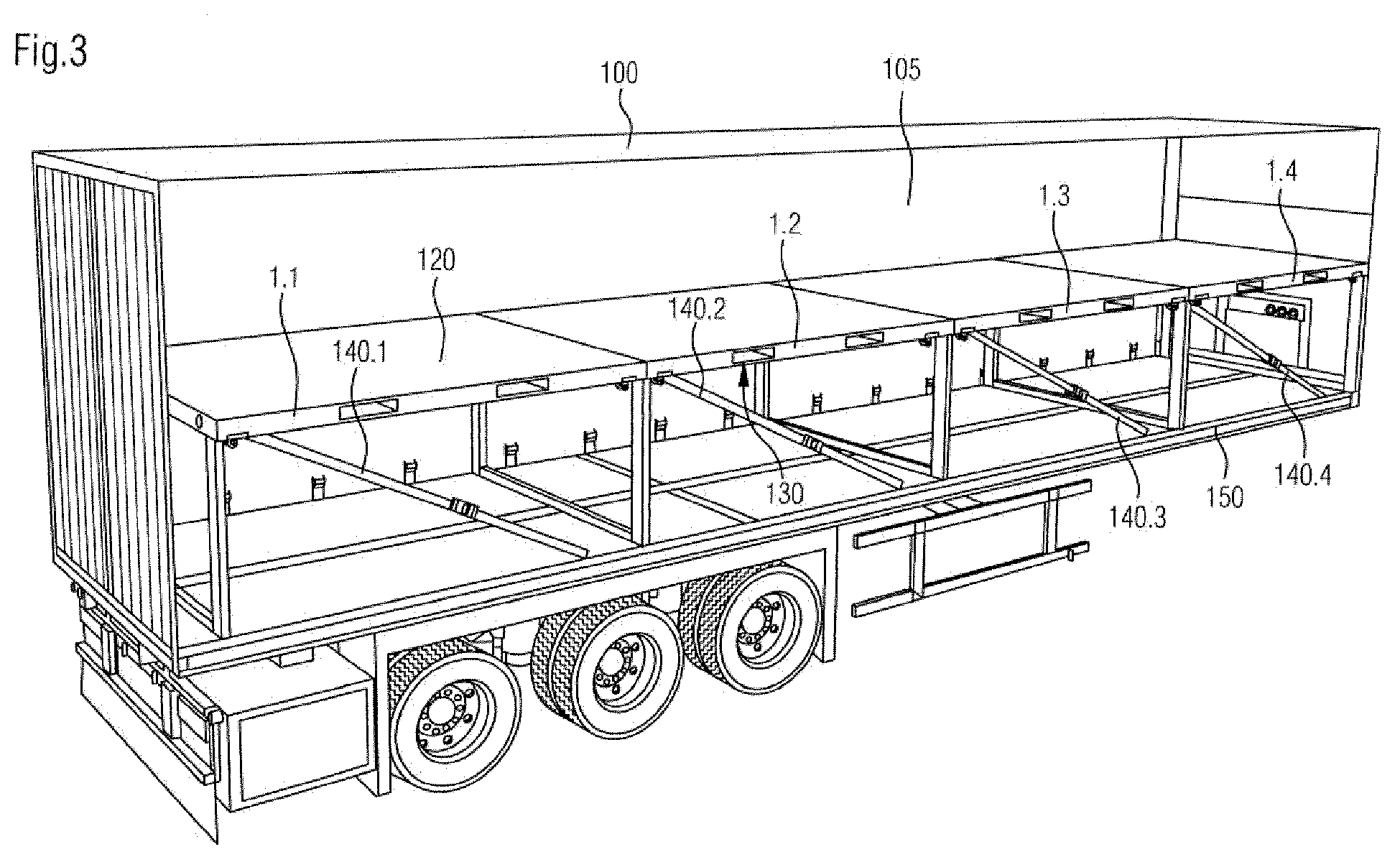
- a semi-trailer 100 having cargo bay 105 having a floor 130 that receives a mobile charging system 120.
- the mobile charging system 120 consists in the present case of four juxtaposed frames 1.1, 1.2, 1.3, 1.4, each receiving a loading floor 130.
- the loading floor 130 is preferably a screen printing plate floor, preferably made of wood.
- the individual racks 1.1, 1.2, 1.3, 1.4 of the mobile charging system 120 are lashed in the semi-trailer 100 with clamping devices 140.1, 140.2, 140.3, 140.4.
- the clamping devices 140.1, 140.2, 140.3 140.4 are straps, preferably polyester straps, preferably with a width of 50 mm.
- the bracing of the individual frames 140.1, 140.2, 140.3, 140.4 takes place in that the tension straps engage in existing in the bottom of the loading space shots, in particular lashing points.
- the frame includes shots for the straps.
- the lashing points in the floor of the loading space of the vehicle are preferably lashing points according to DIN EN 12 640.
- the frame is lashed with at least two tensioning straps, as shown, preferably with four tensioning straps (not shown).
- the four racks arranged side by side form a continuous loading floor 130. How out FIG. 3
- the loading space 105 can be configured by the mobile charging system 120 with an additional loading floor 130, which can be loaded from all four sides, in particular from the front, from behind and from the side. Out FIG.
- the loading floor can extend over the entire length of the semitrailer 100 as shown. However, it would also be possible to exploit only partially the length of the semi-trailer. Since the height of the feet of the racks can be adjusted, the additional loading floor can also be adjusted in height. Also, the setting of different heights of individual racks is possible.
- Each frame 1.1, 1.2, 1.3, 1.4 is placed on the floor 150 of the semi-trailer 100 and is supported by the floor 150 of the semi-trailer 100. Especially good to see in Fig. 3 the modular design of the mobile transport system according to the invention.
- the modular design of the mobile charging system ensures maximum flexibility when loading a vehicle. It also makes it easy to adapt the system to different lengths of the cargo space. Another advantage of the system is that it introduces forces to an existing cargo floor. By simply lashing, in particular bracing on the existing cargo area, a frame of the mobile charging system can be firmly anchored. Additional stanchions for fixation, as in prior art systems, are not necessary. Due to the self-sufficient structure of the system, the full loading and unloading over the length of the cargo space is provided. Furthermore, in the upper floor also from the side of long parts loadable. Furthermore, the curb weight of a trailer, semi-trailer or vehicle receiving the mobile charging system is hardly increased.
- the mobile charging system can be removed from a loading space so that when the mobile charging system is removed and the same is not used, the full load of the vehicle is retained. Another advantage over the known solutions is that the improved utilization of the loading space is not accompanied by an increase in empty weight. This can reduce emissions.
Landscapes
- Engineering & Computer Science (AREA)
- Transportation (AREA)
- Mechanical Engineering (AREA)
- Health & Medical Sciences (AREA)
- Public Health (AREA)
- Fittings On The Vehicle Exterior For Carrying Loads, And Devices For Holding Or Mounting Articles (AREA)
- Body Structure For Vehicles (AREA)
Abstract
Die Erfindung betrifft ein Mobiles Ladesystem (120) für einen Laderaum (105) mit einem Boden, insbesondere eines Fahrzeuges, bevorzugt mit einem Fahrzeugrahmen , dadurch gekennzeichnet, dass
das mobile Ladesystem wenigstens ein Gestell (1, 1.1, 1.2, 1.3, 1.4), das einen Ladeboden (130) bevorzugt mit einer Stärke im Bereich 5-40 mm, insbesondere 25-30 mm trägt, umfasst.
the mobile charging system comprises at least one frame (1, 1.1, 1.2, 1.3, 1.4) carrying a loading floor (130) preferably with a thickness in the range 5-40 mm, in particular 25-30 mm.
Description
Die Erfindung betrifft ein mobiles Ladesystem für einen Laderaum insbesondere eines Fahrzeuges, bevorzugt mit einem Fahrzeugrahmen. Der Laderaum weist einen Boden auf. Es besteht generell das Bedürfnis Laderaum, beispielsweise bei Speditionen, besser als bislang auszunutzen. Eine aus dem Stand der Technik bekannte Möglichkeit bestand z.B. darin, in verstärkten Rungen, die in den Boden des Laderaums eingelassen sind, Holme einzuhängen, die dann mit zusätzlichem Ladegut beladen werden konnten. Diese Systeme hatten den Nachteil, dass eine seitliche Be- und Entladung von Ladegut mit Abmessungen über dem Abstand der Rungen, insbesondere von Langmaterial nicht möglich war. Zudem waren die Rungen unflexibel.The invention relates to a mobile charging system for a cargo space, in particular of a vehicle, preferably with a vehicle frame. The cargo compartment has a floor. There is a general need to use hold, for example, in freight forwarders, better than before. A possibility known from the prior art existed e.g. to mount spars in reinforced stakes set in the floor of the cargo hold, which could then be loaded with additional cargo. These systems had the disadvantage that a lateral loading and unloading of cargo with dimensions above the distance of the stanchions, in particular of long material was not possible. In addition, the stanchions were inflexible.
Aus der
Nachteilig an dem System der
Die
Aus der
Aufgabe der Erfindung ist es somit, ein mobiles Ladesystem anzugeben, das den Laderaum beispielsweise eines Lastkraftwagens besser als bislang ausnutzt und die Nachteile des Standes der Technik vermeidet.The object of the invention is therefore to provide a mobile charging system that better exploits the load space of a truck, for example, and avoids the disadvantages of the prior art.
Erfindungsgemäß wird diese Aufgabe dadurch gelöst, dass ein mobiles Ladesystem für einen Laderaum, insbesondere eines Fahrzeuges, mit einem Boden angegeben wird, das sich dadurch auszeichnet, dass das Ladesystem wenigstens ein Gestell, das einen Ladeboden bevorzugt mit einer Stärke im Bereich 15 - 40 mm, insbesondere 25 - 30 mm trägt, umfasst. Das Gestell kann beispielsweise mittels eines Gabelstaplers in den Laderaum eines Fahrzeuges verbracht werden, falls die Beladung des Laderaumes insbesondere die Stellfläche unter Ausnutzung der gegebenen Laderaumhöhe erhöht werden soll. Das Gestell wird dann auf dem Boden des Laderaumes abgestellt und über Zurrgurte, die zu den bei jedem Ladeboden eines Fahrzeuges vorhandenen Aufnahmen in Form von Zurrpunkten geführt werden, verspannt und gesichert. Die Aufnahmen bzw. Zurrpunkte können auch am Fahrzeugaußenrahmen angeordnet sein. Die Zurrgurte für das mobile Ladesystem zum Verzurren des Gestelles mit dem Ladeboden auf dem Boden des Laderaums greifen auch in Aufnahmen des Gestells ein. Bevorzugt wird das Gestell auf dem Boden des Laderaums mit Zurrgurten, bevorzugt 50 mm breite Polyesterzurrgurten gemäß DIN EN 12 195-2 LC 2.500 daN, die durch die Aufnahmen bzw. die Zurrpunkte von Gestell und Boden des Laderaumes geführt werden, gehalten.According to the invention this object is achieved in that a mobile charging system for a cargo space, in particular a vehicle, is specified with a floor, which is characterized in that the charging system at least one frame, preferably a loading floor with a thickness in the range 15- 40 mm , in particular 25-30 mm, comprises. The frame can be spent, for example by means of a forklift in the hold of a vehicle, if the loading of the hold, in particular the footprint to be increased by taking advantage of the given hold height. The frame is then placed on the floor of the hold and braced over lashing straps, which are led to the present at each loading floor of a vehicle shots in the form of lashing points, and secured. The recordings or lashing points can also be arranged on the vehicle outer frame. The lashing straps for the mobile charging system for lashing the frame with the loading floor on the floor of the load compartment also intervene in recordings of the frame. Preferably, the frame is held on the floor of the cargo space with lashing straps, preferably 50 mm wide polyester lashing straps in accordance with DIN EN 12 195-2 LC 2,500 daN, which are guided by the receptacles or the lashing points of the frame and bottom of the cargo space.
Um zu gewährleisten, dass die Beladung bei formschlüssiger Beladung nicht zur Seite verrutschen kann, können stabil ausgeführte Bordwände oder beidseitige Palettenanschlagleisten nach DIN EN 12 642 6 Code XL eingesetzt werden.In order to ensure that the load can not shift to the side in the event of positive loading, sturdy side walls or double-sided pallet stop strips in accordance with DIN EN 12 642 6 Code XL can be used.
Alternativ kann die seitliche Ladungssicherung durch Antirutschmatten zwischen den Ladeeinheiten und dem Fahrzeugboden durchgeführt werden. Die verwendeten Antirutschmatten müssen mindestens einen Reibwert von µ= 0,6 aufweisen und auf das Ladeeinheitengewicht abgestimmt sein. Die Antirutschmatten können bevorzugt jeweils quer zur Fahrtrichtung unter den Doppelstockverladeboden gelegt werden. Ein derartiges System lässt einen modularen Aufbau eines zusätzlichen Ladebodens zu, insbesondere kann der Laderaum ein oder mehrere nebeneinander und übereinander angeordnete Gestelle mit Ladeboden umfassen. Der modulare Aufbau kann somit sehr flexibel in seinen Abmessungen ausgestaltet werden.Alternatively, the lateral load securing can be carried out by anti-slip mats between the loading units and the vehicle floor. The anti-slip mats used must have at least a coefficient of friction of μ = 0.6 and be matched to the loading unit weight. The anti-slip mats can preferably be placed transversely to the direction of travel under the double-deck loading floor. Such a system allows for a modular construction of an additional loading floor, in particular the loading space can comprise one or more shelves with a loading floor arranged side by side and one above the other. The modular structure can thus be designed very flexible in its dimensions.
Ein solches mobiles Ladesystem ist nicht an einen spezifischen und vorbereiteten Aufbau oder Laderaum gebunden. Es kann beispielsweise bei Standard-Sattelaufliegern, Anhängern oder Aufbauten unabhängig vom Hersteller eingesetzt werden. Das mobile Ladesystem wird lediglich seitlich mit dem vorhandenen Laderaum verspannt und damit befestigt. Dies hat zum Vorteil, dass vorhandene Zertifizierungen betreffend den genutzten Laderaum erhalten bleiben und nicht durch das mobile Ladesystem berührt werden.Such a mobile charging system is not tied to a specific and prepared structure or cargo space. For example, it can be used on standard semi-trailers, trailers or bodies independent of the manufacturer. The mobile charging system is only laterally braced with the existing cargo space and thus secured. This has the advantage that existing certifications regarding the cargo space used are preserved and are not affected by the mobile charging system.
Da das mobile Ladesystem vorhandene Laderäume nutzt, müssen diese zur Aufnahme des Ladesystems auch nicht geändert werden. So bleiben sämtliche Lademöglichkeiten, beispielsweise Heckverteiler und Türen des Laderaumes erhalten. Es sind für die Nutzung keinerlei Um-oder Ausbauten am vorhandenen Laderaum nötig.Since the mobile charging system uses existing holds, they do not need to be changed to accommodate the charging system. This way, all charging options, such as rear distributors and doors of the cargo hold, are retained. There are no conversions or extensions to the existing cargo space required for use.
In einer bevorzugten Ausgestaltung der Erfindung ist vorgesehen, dass das Gestell des mobilen Ladesystems derart ausgestaltet ist, dass der Ladeboden auf dem Gestell aus allen Richtungen zug- und druckbelastet werden kann. Dadurch ist eine Beladung von allen Seiten möglich und Beschränkungen der Ladeweise fallen weg. Der mit dem mobilen Ladeboden ausgestattete Laderaum kann dann von allen beim vorhandenen und genutzten Aufbau gegebenen Seiten be- und entladen werden. Bevorzugt sind das Gestell und der Ladeboden derart ausgelegt, dass eine maximale Zuladung von 3000 kg symmetrisch und homogen über die Ladefläche verteilt vom Ladeboden des Gestelles aufgenommen werden kann. Besonders bevorzugt beträgt die maximale einstellbare Höhe des Gestelles mit Ladeboden 1800 mm.
Besonders bevorzugt ist es, wenn das Gestell wenigstens vier Füße umfasst, die bevorzugt derart ausgebildet sind, dass sie in ihrer Höhe variabel einstellbar sind. Bevorzugt sind die Füße in der Höhe im Bereich von 0,5 m bis 3,0 m Höhe bevorzugt 1,1 m - 2,2 m Höhe, höhenverstellbar. Durch die Höhenverstellung ist es möglich, den Laderaum maximal in der Höhe auszunutzen.In a preferred embodiment of the invention, it is provided that the frame of the mobile charging system is designed such that the loading floor on the frame can be tension and pressure loaded from all directions. As a result, loading from all sides is possible and restrictions on charging are eliminated. The loading space equipped with the mobile loading floor can then be loaded and unloaded by all sides provided with the existing and used construction. Preferably, the frame and the loading floor are designed such that a maximum payload of 3000 kg can be accommodated symmetrically and homogeneously distributed over the loading area from the loading floor of the rack. Particularly preferably, the maximum adjustable height of the frame with loading floor is 1800 mm.
It is particularly preferred if the frame comprises at least four feet, which are preferably designed such that they are variably adjustable in height. Preferably, the feet in height in the range of 0.5 m to 3.0 m in height, preferably 1.1 m - 2.2 m in height, height adjustable. Due to the height adjustment, it is possible to make maximum use of the cargo space in height.
Besonders bevorzugt ist es, wenn das Gestell in Einzelteile wie Ladeboden und Gestellteile z.B. Füße zerlegt werden kann. Der Zusammenbau des Gestelles erfolgt dann bevor das Gestell mit dem Ladeboden in den Laderaum gebracht wird. Hierzu können zunächst die einzelnen Füße beispielsweise in einer Schiene aufgestellt und fixiert werden. Auf die insgesamt vier Füße kann dann der Ladeboden beispielsweise mittels eines Gabelstaplers aufgesetzt werden. Nach Aufsetzen des Ladebodens auf die vier Füße wird der Ladeboden an den Füßen gesichert, beispielsweise durch Bolzen. Um die Platte abzuheben oder die Höhe der Füße zu verändern werden die Bolzen gelöst. Dieser Aufbau stellt ein zerlegbares mobiles Ladesystem zur Verfügung, das je nach Bedarf zusammen- oder abgebaut werden kann.It is particularly preferred if the frame is divided into individual parts such as loading floor and frame parts, e.g. Feet can be disassembled. The assembly of the frame is then carried out before the frame is brought to the loading floor in the hold. For this purpose, the individual feet can first be set up and fixed in a rail, for example. On the four feet can then be placed on the loading floor, for example by means of a forklift. After placing the loading floor on the four feet, the loading floor is secured to the feet, for example by bolts. To lift the plate or to change the height of the feet, the bolts are released. This design provides a collapsible mobile charging system that can be assembled or disassembled as needed.
Um das Gestell mit einer hohen Standsicherheit zu versehen ist vorgesehen, dass die Füße in eine Schiene, bevorzugt eine U-förmige Schiene eingreifen, die als Auflage, auf dem Boden des Laderaums dient. Durch die U-förmige Schiene wird die Last des Gestells flächig auf den Boden des Laderaumes verteilt.To provide the frame with a high stability is provided that the feet engage in a rail, preferably a U-shaped rail, which serves as a support, on the floor of the hold. Through the U-shaped rail, the load of the frame is distributed flat to the floor of the hold.
In einer weitergebildeten Ausführungsform der Erfindung ist vorgesehen, dass der Ladeboden bevorzugt Siebdruckplatten umfasst. Die Siebdruckplatten mit einer Stärke von 15 mm - 40 mm, insbesondere 25 mm - 30 mm sind ausreichend stark ausgebildet, um auch mit hohen Gewichten beladen zu werden. Der Ladeboden ist so ausgelegt, dass Flächengewichte von mindestens 500 kg/m2, bevorzugt im Bereich 500 kg/m2 bis 5000 kg/m2, insbesondere 500 kg/m2 bis 2000 kg/m2 abgetragen werden können. Wenn ein Gestell mit einem derartigen Ladeboden aus Siebdruckplatten auf den Boden des Laderaums abgesenkt ist, ist es möglich, diesen Ladeboden auch mit Gabelstaplern, Elektroameisen oder ähnlichen schweren Hilfsmitteln und Maschinen zum Be- und Entladen zu befahren.In a further developed embodiment of the invention, it is provided that the loading floor preferably comprises screen printing plates. The screen printing plates with a thickness of 15 mm - 40 mm, in particular 25 mm - 30 mm are sufficiently strong to be loaded even with high weights. The loading floor is designed so that basis weights of at least 500 kg / m 2 , preferably in the range 500 kg / m 2 to 5000 kg / m 2 , in particular 500 kg / m 2 to 2000 kg / m 2 can be removed. If a rack with such a loading floor of screen printing plates is lowered to the bottom of the hold, it is possible to use this loading floor with forklifts, electric ants or similar heavy tools and machinery to load and unload.
Eine ausreichende Tragfähigkeit des Gestells für die auf dem Gestell angeordneten Siebdruckplatten wird dadurch sichergestellt, dass das Gestell neben einer Umfassung auch Längs- und Querstreben zur Versteifung des Gestells umfasst. Durch ein derart aufgebautes Gestell können Querlasten oder Drucklasten oder Zuglasten von wenigstens 1 Tonne in alle Richtungen abgetragen werden. Das Gestell umfasst bei einer Breite von beispielsweise 2,44 m und einer Länge von beispielsweise 3,4 m - 4,0 m insgesamt zwei in die Umfassung des Gestelles eingebrachte Querstreben und zwei in die Umfassung des Gestelles eingebrachte Längsstreben. Die angegebenen Abmessungen sind beispielhaft und nicht einschränkend. Bevorzugt ist der Längs- und/oder Querstreben sowie die Umfassung aus einem Blechmaterial hergestellt, insbesondere aus einem gelaserten und gekanteten Blech. Die Stärke des gelaserten und gekanteten Bleches beträgt bevorzugt zwischen 3 mm - 8 mm bevorzugt zwischen 4 mm - 6 mm insbesondere 5 mm. Mit einem Blechmaterial mit einer Stärke im Bereich von 5 mm aus einem Stahl, insbesondere einem Edelstahl, bevorzugt V2A1.4301 Edelstahl wird ein sehr leichtes, aber dennoch ausreichend starkes Gestell zur Aufnahme von Lasten von wenigstens 4 Tonnen Traglast und wenigstens 1 Tonne seitliche Belastung zur Verfügung gestellt. Das sehr leichte Gestell mit dem sehr leichten Boden, hat ein sehr geringes Gewicht, weswegen durch Einbringen des mobilen Laderaums die Beladungskapazität nicht stark reduziert wird.A sufficient load capacity of the frame for the arranged on the frame screen printing plates is ensured by the fact that the frame includes not only an enclosure and longitudinal and transverse struts to stiffen the frame. By means of a frame constructed in this way, transverse loads or compressive loads or tensile loads of at least 1 ton can be removed in all directions. The frame comprises at a width of for example 2.44 m and a length of for example 3.4 m - 4.0 m, a total of two introduced into the enclosure of the frame cross struts and two introduced into the enclosure of the frame longitudinal struts. The dimensions given are exemplary and not limiting. Preferably, the longitudinal and / or transverse struts and the enclosure is made of a sheet metal material, in particular of a lasered and folded sheet metal. The thickness of the lasered and folded sheet is preferably between 3 mm - 8 mm, preferably between 4 mm - 6 mm, in particular 5 mm. With a sheet material with a thickness in the range of 5 mm from a steel, in particular a stainless steel, preferably V2A1.4301 stainless steel is a very light, but sufficiently strong rack to accommodate loads of at least 4 tons load and at least 1 ton of lateral load to Provided. The very light frame with the very light bottom, has a very low weight, so the load capacity is not greatly reduced by introducing the mobile cargo space.
Es ist somit möglich, mit dem mobilen Ladeboden die Nutzungskapazität des vorhandenen Laderaumes sehr stark zu erhöhen.It is thus possible to greatly increase the utilization capacity of the existing loading space with the mobile loading floor.
Um bei mehreren Böden auf einem LKW diese sichern zu können, umfasst das Gestell eine Hakensicherung, die mit einem Bolzen arretiert wird.
Neben dem mobilen Ladesystem stellt die Erfindung auch ein Fahrzeug mit einem derartigen mobilen Ladesystem zur Verfügung. Hierbei umfasst das Fahrzeug einen Laderaum, wobei in den Boden des Laderaums und/oder des Fahrzeugrahmens Aufnahmen, beispielsweise Zurrpunkte eingelassen sind, in die wenigstens zwei, bevorzugt vier Zurrgurte eingreifen können und mit denen das in den Laderaum eingebrachte Gestell verspannt werden kann. Hierzu umfasst auch das Gestell Aufnahmen, in die die Verzurrgurte eingebracht werden können. Selbstverständlich kann der Laderaum auch mehr als ein Gestell aufnehmen, beispielsweise zwei hintereinander liegende Gestelle. Die hintereinander liegenden Gestelle können getrennt voneinander angeordnet sein wie beschrieben oder verbunden, so dass sie eine mechanische Einheit ausbilden. Verwendung findet das mobile Ladesystem als mobiler Doppelstockboden im Laderaum eines Fahrzeuges.In order to be able to secure these on several trucks on a truck, the frame comprises a hook safety device, which is locked with a bolt.
In addition to the mobile charging system, the invention also provides a vehicle with such a mobile charging system. Here, the vehicle comprises a cargo space, wherein in the bottom of the cargo space and / or the vehicle frame shots, such as lashing points are embedded, can engage in the at least two, preferably four lashing straps and with which the introduced into the cargo rack can be braced. For this purpose, the frame recordings in which the lashing straps can be introduced. Of course, the cargo space can accommodate more than one frame, for example, two consecutive racks. The successive racks can be arranged separately from each other as described or connected, so that they form a mechanical unit. The mobile charging system is used as a mobile double-decker floor in the cargo hold of a vehicle.
Nachfolgend soll die Erfindung ohne Beschränkung hierauf an einem Ausführungsbeispiel beschrieben werden.Hereinafter, the invention will be described without limitation thereto on an embodiment.
Es zeigen:
- Fig. 1
- Ein erfindungsgemäßes Gestell zur Aufnahme eines Ladebodens
- Fig. 2
- Zwei neben einander angeordnete Gestelle, darstellend den modularen Aufbau des mobilen Ladesystems
- Fig. 3
- ein Sattelauflieger mit mobilem Ladesystem
- Fig. 1
- An inventive frame for receiving a loading floor
- Fig. 2
- Two racks arranged next to each other, representing the modular structure of the mobile charging system
- Fig. 3
- a semi-trailer with mobile charging system
In
Das Gestell 1 umfasst insgesamt in der dargestellten Ausführungsform 4 verstellbare Füße 3.1, 3.2, 3.3, 3.4. Die verstellbaren Füße 3.1, 3.2 sowie 3.3, 3.4 sind in eine U-förmige Schiene 4.1 beziehungsweise 4.2 eingelassen. Die U-förmige Schiene 4.1, 4.2 dient der Auflage, auf den Boden des Laderaums auf das das mobile Ladesystem aufgebracht wird. Durch die U-förmige ausgestaltete Schiene 4.1, 4.2 wird die Last, die vom Gestell über die Füße in die Schiene eingeleitet wird, flächig über den Boden des Laderaums, auf dem das mobile Ladesystem aufgebracht wird, verteilt. Die Füße münden in eine Umfassung 10, die mit Längsstreben 12.1, 12.2 und Querstreben 13.1, 13.2 verstärkt werden kann. Die Umfassung besitzt zwei Seitenteile 16.1, 16.2 sowie zwei Längsteile 18.1,18.2.The frame 1 comprises a total of 4 adjustable feet 3.1, 3.2, 3.3, 3.4 in the illustrated embodiment. The adjustable feet 3.1, 3.2 and 3.3, 3.4 are embedded in a U-shaped rail 4.1 or 4.2. The U-shaped Rail 4.1, 4.2 serves the support, on the floor of the hold on which the mobile charging system is applied. By means of the U-shaped rail 4.1, 4.2, the load, which is introduced from the frame via the feet into the rail, is distributed over the floor of the cargo space on which the mobile charging system is applied. The feet open into a
Auf die Umfassung 10 und die Längsstreben 12.1, 12.2 wird der Ladeboden (nicht dargestellt) aufgebracht, beispielsweise durch Aufsetzen mit einem Gabelstapler. Der Plattenboden wird dann auf dem Gestell z.B. mit Bolzen gesichert. Das Gestell ist in seine Einzelteile zerlegbar. Dadurch das Gestell und Ladeboden separate Bauteile sind, ist das System sehr flexibel. Die Umfassung 10 und die Längs- 12.1, 12.2, bzw. Querstreben 13.1, 13.2 tragen den Ladeboden und leiten die über den Ladeboden eingeleiteten Kräfte über die Füße 3.1, 3.2, 3.3, 3.4 auf den Boden des Laderaums auf dem das Gestell 1 des mobilen Ladesystems aufgesetzt wird. Die Elemente der Umfassung 10 sowie die Quer- und Längsstreben umfassen bevorzugt ein Blechmaterial mit einer Stärke von 5 mm, bevorzugt handelt es sich hierbei um gelaserte und gekantete Bleche, wobei die Bleche beispielsweise zu der Umfassung verschweißt werden.On the
Der Boden, bevorzugt der aus Holz, insbesondere aus Siebdruckplatten bestehende Boden, ist mit Nieten oder Schrauben auf dem Gestell befestigt.The floor, preferably made of wood, in particular of screen printing plates existing floor is fastened with rivets or screws on the frame.
In
In
Der modulare Aufbau des mobilen Ladesystems sorgt für eine größtmögliche Flexibilität bei der Beladung eines Fahrzeuges. Auch ermöglicht er es, das System an unterschiedliche Längen des Laderaumes einfach anzupassen. Ein weiterer Vorteil des Systems ist, dass es die Kräfte auf einen vorhandenen Ladeboden einleitet. Durch einfaches Verzurren, insbesondere Verspannen auf der vorhandenen Ladefläche kann ein Gestell des mobilen Ladesystems fest verankert werden. Zusätzliche Rungen zur Fixierung, wie in Systemen nach dem Stand der Technik sind nicht nötig. Durch den autarken Aufbau des Systems, wird die volle Be- und Entladung über die Länge des Laderaumes zur Verfügung gestellt. Des Weiteren sind in der oberen Etage auch von der Seite lange Teile ladbar. Des Weiteren wird das Leergewicht eines Anhänger, Aufliegers oder Fahrzeuges, das das mobile Ladesystem aufnimmt, kaum erhöht. Das mobile Ladesystem ist aus einem Laderaum herausnehmbar, so dass bei herausgenommenem mobilen Ladesystem und Nichtbenutzung desselben, die volle Zuladung des Fahrzeuges erhalten bleibt. Ein weiterer Vorteil gegenüber den bekannten Lösungen ist, dass die verbesserte Ausnutzung des Laderaumes nicht mit einem Mehr an Leergeweicht einhergeht. Hierdurch können Emissionen verringert werden.The modular design of the mobile charging system ensures maximum flexibility when loading a vehicle. It also makes it easy to adapt the system to different lengths of the cargo space. Another advantage of the system is that it introduces forces to an existing cargo floor. By simply lashing, in particular bracing on the existing cargo area, a frame of the mobile charging system can be firmly anchored. Additional stanchions for fixation, as in prior art systems, are not necessary. Due to the self-sufficient structure of the system, the full loading and unloading over the length of the cargo space is provided. Furthermore, in the upper floor also from the side of long parts loadable. Furthermore, the curb weight of a trailer, semi-trailer or vehicle receiving the mobile charging system is hardly increased. The mobile charging system can be removed from a loading space so that when the mobile charging system is removed and the same is not used, the full load of the vehicle is retained. Another advantage over the known solutions is that the improved utilization of the loading space is not accompanied by an increase in empty weight. This can reduce emissions.
Claims (15)
dadurch gekennzeichnet, dass
das mobile Ladesystem wenigstens ein Gestell (1), das einen Ladeboden bevorzugt mit einer Stärke im Bereich 5-40 mm, insbesondere 25-30 mm trägt, umfasst.Mobile charging system for a cargo space with a floor, in particular of a vehicle, preferably with a vehicle frame,
characterized in that
the mobile charging system comprises at least one frame (1), which preferably carries a loading floor with a thickness in the range 5-40 mm, in particular 25-30 mm.
dadurch gekennzeichnet, dass
das Gestell wenigstens zwei bevorzugt vier erste Aufnahmen, insbesondere Zurrpunkte für Verspanneinrichtungen, umfasst.Mobile charging system according to claim 1,
characterized in that
the frame at least two preferably four first images, in particular lashing points for Verspanneinrichtungen includes.
dadurch gekennzeichnet, dass
der Boden des Laderaumes und/oder der Fahrzeugrahmen wenigstens zwei bevorzugt vier zweite Aufnahmen, insbesondere Zurrpunkte zur Aufnahme für Verspanneinrichtung, insbesondere Zurrgurte umfasst.Mobile charging system according to claim 2,
characterized in that
the bottom of the loading space and / or the vehicle frame at least two preferably four second receptacles, in particular lashing points for receiving for bracing, in particular lashing straps comprises.
dadurch gekennzeichnet, dass
der Ladeboden Anschlagleisten und/oder Antirutschmatten, bevorzugt mit einem Reibwert von mindestens µ = 0,6 umfasst.Mobile charging system according to one of claims 1 to 3,
characterized in that
the loading floor comprises stop strips and / or anti-slip mats, preferably with a coefficient of friction of at least μ = 0.6.
dadurch gekennzeichnet, dass
der Ladeboden auf dem Gestell (1) derart ausgestaltet ist, dass er aus allen Richtungen zug- und druckbelastet werden kann.Mobile charging system according to one of claims 1 to 4,
characterized in that
the loading floor on the frame (1) is designed such that it can be zug- and pressure-loaded from all directions.
dadurch gekennzeichnet, dass
das Gestell (1) wenigstens vier Füße (3.1, 3.2, 3.3, 3.4), insbesondere in der Höhe verstellbare Füße, bevorzugt im Bereich 0,5 m - 3,0 m bevorzugt 1,1 m - 2,2 m in der Höhe verstellbare Füße umfasst.Mobile charging system according to one of claims 1 to 5,
characterized in that
the frame (1) at least four feet (3.1, 3.2, 3.3, 3.4), in particular height-adjustable feet, preferably in the range 0.5 m - 3.0 m, preferably 1.1 m - 2.2 m in height includes adjustable feet.
dadurch gekennzeichnet, dass
das Gestell (1) eine Schiene (4.1, 4.2) umfasst, in die die Füße (3.1, 3.2, 3.3, 3.4) eingreifen.Mobile charging system according to claim 3,
characterized in that
the frame (1) comprises a rail (4.1, 4.2) into which the feet (3.1, 3.2, 3.3, 3.4) engage.
dadurch gekennzeichnet, dass
der Ladeboden bevorzugt Siebdruckplatten, bevorzugt aus Holz umfasst und/oder befahrbar ausgestaltet ist.Mobile charging system according to one of claims 1 to 4,
characterized in that
the loading floor preferably comprises screen printing plates, preferably made of wood and / or designed passable.
dadurch gekennzeichnet, dass
das Gestell (1) eine Umfassung (10) und/oder Querstreben (13.1, 13.2) in der Umfassung (10) aufweist.Mobile charging system according to one of claims 1 to 8,
characterized in that
the frame (1) has a surround (10) and / or transverse struts (13.1, 13.2) in the enclosure (10).
dadurch gekennzeichnet, dass
der Ladeboden und das Gestell separate Bauteile sind, die miteinander verbunden und/oder voneinander gelöst werden können.Mobile charging system according to one of claims 1 to 9,
characterized in that
the loading floor and the frame are separate components that can be connected to each other and / or detached from each other.
dadurch gekennzeichnet, dass
die Umfassung (10), die Längs- (12.1, 12.2) und/oder Querbalken (13.1, 13.2) gelasert und/oder gekanntete Bleche bevorzugt mit einer Stärke im Bereich 3 mm - 8 mm, ganz besonders bevorzugt 4 mm - 6 mm, insbesondere 5 mm umfasst.Mobile charging system according to one of claims 1 to 10,
characterized in that
the enclosure (10), the longitudinal (12.1, 12.2) and / or transverse bars (13.1, 13.2) lasered and / or identified plates preferably with a thickness in the range 3 mm - 8 mm, most preferably 4 mm - 6 mm, in particular 5 mm.
dadurch gekennzeichnet, dass
das Gestell Hakensicherungen umfasst.Mobile charging system according to one of claims 1 to 11,
characterized in that
the frame includes hook retainers.
dadurch gekennzeichnet, dass
der Laderaum des Fahrzeuges wenigstens ein mobiles Ladesystem gemäß einem der Ansprüche 1 bis 12 aufnimmt das mit Verspanneinrichtungen in den Aufnahmen des Bodens des Laderaumes verzurrt sind.Vehicle, in particular with a vehicle frame having a loading space, which comprises a floor, wherein the floor of the loading space and / or the vehicle frame comprises at least two, preferably four seats, in particular lashing points for holding bracing devices, in particular lashing loads,
characterized in that
the cargo space of the vehicle at least one mobile charging system according to one of claims 1 to 12 receives the lashed with bracing devices in the receptacles of the bottom of the cargo space.
dadurch gekennzeichnet, dass
der Laderaum des Fahrzeuges mehrere nebeneinander und/oder übereinander angeordnet mobile Ladesysteme gemäß einem der Ansprüche 1 bis 12 umfasst.Vehicle according to claim 13,
characterized in that
the loading space of the vehicle comprises a plurality of juxtaposed and / or stacked mobile charging systems according to one of claims 1 to 12.
als mobiler Doppelstockboden in einem Laderaum eines Fahrzeuges.Use of a mobile charging system according to one of claims 1 to 12,
as a mobile double-decker floor in a loading space of a vehicle.
Applications Claiming Priority (1)
| Application Number | Priority Date | Filing Date | Title |
|---|---|---|---|
| DE102016206703 | 2016-04-20 |
Publications (2)
| Publication Number | Publication Date |
|---|---|
| EP3235682A1 true EP3235682A1 (en) | 2017-10-25 |
| EP3235682B1 EP3235682B1 (en) | 2020-03-18 |
Family
ID=58544787
Family Applications (1)
| Application Number | Title | Priority Date | Filing Date |
|---|---|---|---|
| EP17165859.4A Active EP3235682B1 (en) | 2016-04-20 | 2017-04-11 | Mobile loading system |
Country Status (2)
| Country | Link |
|---|---|
| EP (1) | EP3235682B1 (en) |
| DE (2) | DE202017001918U1 (en) |
Citations (7)
| Publication number | Priority date | Publication date | Assignee | Title |
|---|---|---|---|---|
| US6027290A (en) * | 1995-11-13 | 2000-02-22 | Lohr Industrie | Structural assembly forming an additional movable deck on a road vehicle |
| WO2002081339A1 (en) * | 2001-03-22 | 2002-10-17 | Permar Oy | Transport container and method for transporting palleted cargo in the transport container |
| DE102005026619A1 (en) | 2005-03-31 | 2006-10-05 | Dümer, Peter | Bars connecting unit for e.g. transport vehicle, has parallel adsorption slots oriented in longitudinal direction of bars, and side blade with cross section designed corresponding to one slot, where unit is designed in L-shape or U-shape |
| JP2007045269A (en) * | 2005-08-08 | 2007-02-22 | Nissan Motor Co Ltd | Vehicle rear structure |
| US20090175698A1 (en) * | 2008-01-09 | 2009-07-09 | Override Decking Systems, Lllp | Modular vehicle transport |
| DE202013103256U1 (en) | 2013-07-21 | 2013-07-25 | Tyroller Hydraulik Herzberg Gmbh | Transport vehicle for transporting a number of similarly shaped, predominantly cuboid packaging containers |
| DE102012011658A1 (en) | 2012-06-13 | 2013-12-19 | Glenn van Doorn | Cargo transport assembly for transporting pallets, has projecting portions and cavities with detachable connection to transmit torque between support beam and supporting portion |
-
2017
- 2017-04-11 DE DE202017001918.3U patent/DE202017001918U1/en not_active Expired - Lifetime
- 2017-04-11 DE DE102017206149.9A patent/DE102017206149A1/en not_active Ceased
- 2017-04-11 EP EP17165859.4A patent/EP3235682B1/en active Active
Patent Citations (7)
| Publication number | Priority date | Publication date | Assignee | Title |
|---|---|---|---|---|
| US6027290A (en) * | 1995-11-13 | 2000-02-22 | Lohr Industrie | Structural assembly forming an additional movable deck on a road vehicle |
| WO2002081339A1 (en) * | 2001-03-22 | 2002-10-17 | Permar Oy | Transport container and method for transporting palleted cargo in the transport container |
| DE102005026619A1 (en) | 2005-03-31 | 2006-10-05 | Dümer, Peter | Bars connecting unit for e.g. transport vehicle, has parallel adsorption slots oriented in longitudinal direction of bars, and side blade with cross section designed corresponding to one slot, where unit is designed in L-shape or U-shape |
| JP2007045269A (en) * | 2005-08-08 | 2007-02-22 | Nissan Motor Co Ltd | Vehicle rear structure |
| US20090175698A1 (en) * | 2008-01-09 | 2009-07-09 | Override Decking Systems, Lllp | Modular vehicle transport |
| DE102012011658A1 (en) | 2012-06-13 | 2013-12-19 | Glenn van Doorn | Cargo transport assembly for transporting pallets, has projecting portions and cavities with detachable connection to transmit torque between support beam and supporting portion |
| DE202013103256U1 (en) | 2013-07-21 | 2013-07-25 | Tyroller Hydraulik Herzberg Gmbh | Transport vehicle for transporting a number of similarly shaped, predominantly cuboid packaging containers |
Also Published As
| Publication number | Publication date |
|---|---|
| DE202017001918U1 (en) | 2017-05-04 |
| EP3235682B1 (en) | 2020-03-18 |
| DE102017206149A1 (en) | 2017-10-26 |
Similar Documents
| Publication | Publication Date | Title |
|---|---|---|
| DE3787973T2 (en) | DEVICE AND METHOD FOR IMPROVING INTERMODAL CONTAINERS FOR THE TRANSPORT OF VEHICLES. | |
| EP2443005B1 (en) | Transport system | |
| EP2441701B1 (en) | Transport device and means of transport therewith | |
| EP2684757B1 (en) | Freight cars | |
| DE10136124C1 (en) | Transporting system for sending good or fittings has rolling modules able to fit in wheel box or side wall shape of freight compartment | |
| DE102013103449A1 (en) | Pallet for transport goods | |
| DE202013102278U1 (en) | Pallet for transport goods | |
| DE102013006764B4 (en) | Loading platform for vehicles | |
| EP2266835A1 (en) | Transport superstructure with stanchions | |
| EP2703216B1 (en) | Commercial vehicle superstructure with load securing for double decker operation | |
| DE202015104766U1 (en) | System for stacking vehicle tires | |
| EP3235682B1 (en) | Mobile loading system | |
| DE10312638A1 (en) | Arrangement for securing coil in coil trough in loading floor of transport vehicle has thrust beam transversely above coil trough for attachment to different longitudinal positions of coil trough | |
| DE102017002463B4 (en) | Container carrier frame | |
| DE19806706A1 (en) | Freight holding device for transport vehicle, e.g. for bottle crates | |
| DE102006058603B4 (en) | Structure for a truck, trailer or the like | |
| DE19706493A1 (en) | Goods vehicle with additional upper load platforms | |
| DE60030509T2 (en) | Arrangement in the cargo hold | |
| DE202005002137U1 (en) | Self loading truck for skip and container has the front edge of a skip or container supported on a trolley running on support rails and locked onto the vehicle for transport | |
| DE949089C (en) | Installation on trucks and trailers, in particular serving as airfield auxiliary devices, whose loading area or loading space can be subdivided by means of partitions | |
| DE20306124U1 (en) | Modular load securing system for articulated lorry, comprising vertical elements, partition, tensioning rope, and horizontal bars | |
| DE102017125972A1 (en) | Removable interior unit, kit for creating such a unit, method for equipping a truck with a removable indoor unit | |
| EP4488117A1 (en) | Commercial vehicle structure with load securing device and method for securing loads | |
| DE202023100716U1 (en) | Installation frame for the detachable attachment of a measuring device arrangement in a vehicle | |
| DE4429474A1 (en) | Loading and transporting platform for box=form construction or container |
Legal Events
| Date | Code | Title | Description |
|---|---|---|---|
| PUAI | Public reference made under article 153(3) epc to a published international application that has entered the european phase |
Free format text: ORIGINAL CODE: 0009012 |
|
| STAA | Information on the status of an ep patent application or granted ep patent |
Free format text: STATUS: THE APPLICATION HAS BEEN PUBLISHED |
|
| AK | Designated contracting states |
Kind code of ref document: A1 Designated state(s): AL AT BE BG CH CY CZ DE DK EE ES FI FR GB GR HR HU IE IS IT LI LT LU LV MC MK MT NL NO PL PT RO RS SE SI SK SM TR |
|
| AX | Request for extension of the european patent |
Extension state: BA ME |
|
| STAA | Information on the status of an ep patent application or granted ep patent |
Free format text: STATUS: REQUEST FOR EXAMINATION WAS MADE |
|
| 17P | Request for examination filed |
Effective date: 20180424 |
|
| RBV | Designated contracting states (corrected) |
Designated state(s): AL AT BE BG CH CY CZ DE DK EE ES FI FR GB GR HR HU IE IS IT LI LT LU LV MC MK MT NL NO PL PT RO RS SE SI SK SM TR |
|
| STAA | Information on the status of an ep patent application or granted ep patent |
Free format text: STATUS: EXAMINATION IS IN PROGRESS |
|
| 17Q | First examination report despatched |
Effective date: 20190628 |
|
| GRAP | Despatch of communication of intention to grant a patent |
Free format text: ORIGINAL CODE: EPIDOSNIGR1 |
|
| STAA | Information on the status of an ep patent application or granted ep patent |
Free format text: STATUS: GRANT OF PATENT IS INTENDED |
|
| INTG | Intention to grant announced |
Effective date: 20191016 |
|
| GRAS | Grant fee paid |
Free format text: ORIGINAL CODE: EPIDOSNIGR3 |
|
| GRAA | (expected) grant |
Free format text: ORIGINAL CODE: 0009210 |
|
| STAA | Information on the status of an ep patent application or granted ep patent |
Free format text: STATUS: THE PATENT HAS BEEN GRANTED |
|
| AK | Designated contracting states |
Kind code of ref document: B1 Designated state(s): AL AT BE BG CH CY CZ DE DK EE ES FI FR GB GR HR HU IE IS IT LI LT LU LV MC MK MT NL NO PL PT RO RS SE SI SK SM TR |
|
| REG | Reference to a national code |
Ref country code: GB Ref legal event code: FG4D Free format text: NOT ENGLISH |
|
| REG | Reference to a national code |
Ref country code: DE Ref legal event code: R096 Ref document number: 502017004250 Country of ref document: DE |
|
| REG | Reference to a national code |
Ref country code: CH Ref legal event code: NV Representative=s name: ISLER AND PEDRAZZINI AG, CH Ref country code: AT Ref legal event code: REF Ref document number: 1245545 Country of ref document: AT Kind code of ref document: T Effective date: 20200415 Ref country code: IE Ref legal event code: FG4D Free format text: LANGUAGE OF EP DOCUMENT: GERMAN |
|
| PG25 | Lapsed in a contracting state [announced via postgrant information from national office to epo] |
Ref country code: RS Free format text: LAPSE BECAUSE OF FAILURE TO SUBMIT A TRANSLATION OF THE DESCRIPTION OR TO PAY THE FEE WITHIN THE PRESCRIBED TIME-LIMIT Effective date: 20200318 Ref country code: NO Free format text: LAPSE BECAUSE OF FAILURE TO SUBMIT A TRANSLATION OF THE DESCRIPTION OR TO PAY THE FEE WITHIN THE PRESCRIBED TIME-LIMIT Effective date: 20200618 Ref country code: FI Free format text: LAPSE BECAUSE OF FAILURE TO SUBMIT A TRANSLATION OF THE DESCRIPTION OR TO PAY THE FEE WITHIN THE PRESCRIBED TIME-LIMIT Effective date: 20200318 |
|
| REG | Reference to a national code |
Ref country code: NL Ref legal event code: MP Effective date: 20200318 |
|
| PG25 | Lapsed in a contracting state [announced via postgrant information from national office to epo] |
Ref country code: SE Free format text: LAPSE BECAUSE OF FAILURE TO SUBMIT A TRANSLATION OF THE DESCRIPTION OR TO PAY THE FEE WITHIN THE PRESCRIBED TIME-LIMIT Effective date: 20200318 Ref country code: LV Free format text: LAPSE BECAUSE OF FAILURE TO SUBMIT A TRANSLATION OF THE DESCRIPTION OR TO PAY THE FEE WITHIN THE PRESCRIBED TIME-LIMIT Effective date: 20200318 Ref country code: HR Free format text: LAPSE BECAUSE OF FAILURE TO SUBMIT A TRANSLATION OF THE DESCRIPTION OR TO PAY THE FEE WITHIN THE PRESCRIBED TIME-LIMIT Effective date: 20200318 Ref country code: GR Free format text: LAPSE BECAUSE OF FAILURE TO SUBMIT A TRANSLATION OF THE DESCRIPTION OR TO PAY THE FEE WITHIN THE PRESCRIBED TIME-LIMIT Effective date: 20200619 Ref country code: BG Free format text: LAPSE BECAUSE OF FAILURE TO SUBMIT A TRANSLATION OF THE DESCRIPTION OR TO PAY THE FEE WITHIN THE PRESCRIBED TIME-LIMIT Effective date: 20200618 |
|
| REG | Reference to a national code |
Ref country code: LT Ref legal event code: MG4D |
|
| PG25 | Lapsed in a contracting state [announced via postgrant information from national office to epo] |
Ref country code: NL Free format text: LAPSE BECAUSE OF FAILURE TO SUBMIT A TRANSLATION OF THE DESCRIPTION OR TO PAY THE FEE WITHIN THE PRESCRIBED TIME-LIMIT Effective date: 20200318 |
|
| PG25 | Lapsed in a contracting state [announced via postgrant information from national office to epo] |
Ref country code: LT Free format text: LAPSE BECAUSE OF FAILURE TO SUBMIT A TRANSLATION OF THE DESCRIPTION OR TO PAY THE FEE WITHIN THE PRESCRIBED TIME-LIMIT Effective date: 20200318 Ref country code: SM Free format text: LAPSE BECAUSE OF FAILURE TO SUBMIT A TRANSLATION OF THE DESCRIPTION OR TO PAY THE FEE WITHIN THE PRESCRIBED TIME-LIMIT Effective date: 20200318 Ref country code: EE Free format text: LAPSE BECAUSE OF FAILURE TO SUBMIT A TRANSLATION OF THE DESCRIPTION OR TO PAY THE FEE WITHIN THE PRESCRIBED TIME-LIMIT Effective date: 20200318 Ref country code: PT Free format text: LAPSE BECAUSE OF FAILURE TO SUBMIT A TRANSLATION OF THE DESCRIPTION OR TO PAY THE FEE WITHIN THE PRESCRIBED TIME-LIMIT Effective date: 20200812 Ref country code: RO Free format text: LAPSE BECAUSE OF FAILURE TO SUBMIT A TRANSLATION OF THE DESCRIPTION OR TO PAY THE FEE WITHIN THE PRESCRIBED TIME-LIMIT Effective date: 20200318 Ref country code: SK Free format text: LAPSE BECAUSE OF FAILURE TO SUBMIT A TRANSLATION OF THE DESCRIPTION OR TO PAY THE FEE WITHIN THE PRESCRIBED TIME-LIMIT Effective date: 20200318 Ref country code: IS Free format text: LAPSE BECAUSE OF FAILURE TO SUBMIT A TRANSLATION OF THE DESCRIPTION OR TO PAY THE FEE WITHIN THE PRESCRIBED TIME-LIMIT Effective date: 20200718 Ref country code: CZ Free format text: LAPSE BECAUSE OF FAILURE TO SUBMIT A TRANSLATION OF THE DESCRIPTION OR TO PAY THE FEE WITHIN THE PRESCRIBED TIME-LIMIT Effective date: 20200318 |
|
| REG | Reference to a national code |
Ref country code: DE Ref legal event code: R097 Ref document number: 502017004250 Country of ref document: DE |
|
| PG25 | Lapsed in a contracting state [announced via postgrant information from national office to epo] |
Ref country code: MC Free format text: LAPSE BECAUSE OF FAILURE TO SUBMIT A TRANSLATION OF THE DESCRIPTION OR TO PAY THE FEE WITHIN THE PRESCRIBED TIME-LIMIT Effective date: 20200318 |
|
| PLBE | No opposition filed within time limit |
Free format text: ORIGINAL CODE: 0009261 |
|
| STAA | Information on the status of an ep patent application or granted ep patent |
Free format text: STATUS: NO OPPOSITION FILED WITHIN TIME LIMIT |
|
| PG25 | Lapsed in a contracting state [announced via postgrant information from national office to epo] |
Ref country code: IT Free format text: LAPSE BECAUSE OF FAILURE TO SUBMIT A TRANSLATION OF THE DESCRIPTION OR TO PAY THE FEE WITHIN THE PRESCRIBED TIME-LIMIT Effective date: 20200318 Ref country code: LU Free format text: LAPSE BECAUSE OF NON-PAYMENT OF DUE FEES Effective date: 20200411 Ref country code: ES Free format text: LAPSE BECAUSE OF FAILURE TO SUBMIT A TRANSLATION OF THE DESCRIPTION OR TO PAY THE FEE WITHIN THE PRESCRIBED TIME-LIMIT Effective date: 20200318 Ref country code: DK Free format text: LAPSE BECAUSE OF FAILURE TO SUBMIT A TRANSLATION OF THE DESCRIPTION OR TO PAY THE FEE WITHIN THE PRESCRIBED TIME-LIMIT Effective date: 20200318 |
|
| REG | Reference to a national code |
Ref country code: BE Ref legal event code: MM Effective date: 20200430 |
|
| 26N | No opposition filed |
Effective date: 20201221 |
|
| PG25 | Lapsed in a contracting state [announced via postgrant information from national office to epo] |
Ref country code: BE Free format text: LAPSE BECAUSE OF NON-PAYMENT OF DUE FEES Effective date: 20200430 Ref country code: PL Free format text: LAPSE BECAUSE OF FAILURE TO SUBMIT A TRANSLATION OF THE DESCRIPTION OR TO PAY THE FEE WITHIN THE PRESCRIBED TIME-LIMIT Effective date: 20200318 |
|
| PG25 | Lapsed in a contracting state [announced via postgrant information from national office to epo] |
Ref country code: IE Free format text: LAPSE BECAUSE OF NON-PAYMENT OF DUE FEES Effective date: 20200411 |
|
| PG25 | Lapsed in a contracting state [announced via postgrant information from national office to epo] |
Ref country code: SI Free format text: LAPSE BECAUSE OF FAILURE TO SUBMIT A TRANSLATION OF THE DESCRIPTION OR TO PAY THE FEE WITHIN THE PRESCRIBED TIME-LIMIT Effective date: 20200318 |
|
| GBPC | Gb: european patent ceased through non-payment of renewal fee |
Effective date: 20210411 |
|
| PG25 | Lapsed in a contracting state [announced via postgrant information from national office to epo] |
Ref country code: GB Free format text: LAPSE BECAUSE OF NON-PAYMENT OF DUE FEES Effective date: 20210411 |
|
| PG25 | Lapsed in a contracting state [announced via postgrant information from national office to epo] |
Ref country code: TR Free format text: LAPSE BECAUSE OF FAILURE TO SUBMIT A TRANSLATION OF THE DESCRIPTION OR TO PAY THE FEE WITHIN THE PRESCRIBED TIME-LIMIT Effective date: 20200318 Ref country code: MT Free format text: LAPSE BECAUSE OF FAILURE TO SUBMIT A TRANSLATION OF THE DESCRIPTION OR TO PAY THE FEE WITHIN THE PRESCRIBED TIME-LIMIT Effective date: 20200318 Ref country code: CY Free format text: LAPSE BECAUSE OF FAILURE TO SUBMIT A TRANSLATION OF THE DESCRIPTION OR TO PAY THE FEE WITHIN THE PRESCRIBED TIME-LIMIT Effective date: 20200318 |
|
| PG25 | Lapsed in a contracting state [announced via postgrant information from national office to epo] |
Ref country code: MK Free format text: LAPSE BECAUSE OF FAILURE TO SUBMIT A TRANSLATION OF THE DESCRIPTION OR TO PAY THE FEE WITHIN THE PRESCRIBED TIME-LIMIT Effective date: 20200318 Ref country code: AL Free format text: LAPSE BECAUSE OF FAILURE TO SUBMIT A TRANSLATION OF THE DESCRIPTION OR TO PAY THE FEE WITHIN THE PRESCRIBED TIME-LIMIT Effective date: 20200318 |
|
| PGFP | Annual fee paid to national office [announced via postgrant information from national office to epo] |
Ref country code: FR Payment date: 20230428 Year of fee payment: 7 Ref country code: CH Payment date: 20230605 Year of fee payment: 7 |
|
| PGFP | Annual fee paid to national office [announced via postgrant information from national office to epo] |
Ref country code: AT Payment date: 20230516 Year of fee payment: 7 |
|
| REG | Reference to a national code |
Ref country code: CH Ref legal event code: PL |
|
| REG | Reference to a national code |
Ref country code: AT Ref legal event code: MM01 Ref document number: 1245545 Country of ref document: AT Kind code of ref document: T Effective date: 20240411 |
|
| PG25 | Lapsed in a contracting state [announced via postgrant information from national office to epo] |
Ref country code: FR Free format text: LAPSE BECAUSE OF NON-PAYMENT OF DUE FEES Effective date: 20240430 |
|
| PG25 | Lapsed in a contracting state [announced via postgrant information from national office to epo] |
Ref country code: AT Free format text: LAPSE BECAUSE OF NON-PAYMENT OF DUE FEES Effective date: 20240411 |
|
| PG25 | Lapsed in a contracting state [announced via postgrant information from national office to epo] |
Ref country code: FR Free format text: LAPSE BECAUSE OF NON-PAYMENT OF DUE FEES Effective date: 20240430 Ref country code: AT Free format text: LAPSE BECAUSE OF NON-PAYMENT OF DUE FEES Effective date: 20240411 Ref country code: CH Free format text: LAPSE BECAUSE OF NON-PAYMENT OF DUE FEES Effective date: 20240430 |
|
| PGFP | Annual fee paid to national office [announced via postgrant information from national office to epo] |
Ref country code: DE Payment date: 20250429 Year of fee payment: 9 |