EP3235611A1 - Robot maintenance assist device and method - Google Patents
Robot maintenance assist device and method Download PDFInfo
- Publication number
- EP3235611A1 EP3235611A1 EP15869779.7A EP15869779A EP3235611A1 EP 3235611 A1 EP3235611 A1 EP 3235611A1 EP 15869779 A EP15869779 A EP 15869779A EP 3235611 A1 EP3235611 A1 EP 3235611A1
- Authority
- EP
- European Patent Office
- Prior art keywords
- current command
- robot
- command value
- tendency
- unit
- Prior art date
- Legal status (The legal status is an assumption and is not a legal conclusion. Google has not performed a legal analysis and makes no representation as to the accuracy of the status listed.)
- Granted
Links
Images


Classifications
-
- G—PHYSICS
- G05—CONTROLLING; REGULATING
- G05B—CONTROL OR REGULATING SYSTEMS IN GENERAL; FUNCTIONAL ELEMENTS OF SUCH SYSTEMS; MONITORING OR TESTING ARRANGEMENTS FOR SUCH SYSTEMS OR ELEMENTS
- G05B19/00—Program-control systems
- G05B19/02—Program-control systems electric
- G05B19/18—Numerical control [NC], i.e. automatically operating machines, in particular machine tools, e.g. in a manufacturing environment, so as to execute positioning, movement or co-ordinated operations by means of program data in numerical form
- G05B19/406—Numerical control [NC], i.e. automatically operating machines, in particular machine tools, e.g. in a manufacturing environment, so as to execute positioning, movement or co-ordinated operations by means of program data in numerical form characterised by monitoring or safety
- G05B19/4065—Monitoring tool breakage, life or condition
-
- B—PERFORMING OPERATIONS; TRANSPORTING
- B25—HAND TOOLS; PORTABLE POWER-DRIVEN TOOLS; MANIPULATORS
- B25J—MANIPULATORS; CHAMBERS PROVIDED WITH MANIPULATION DEVICES
- B25J19/00—Accessories fitted to manipulators, e.g. for monitoring, for viewing; Safety devices combined with or specially adapted for use in connection with manipulators
- B25J19/0066—Means or methods for maintaining or repairing manipulators
-
- B—PERFORMING OPERATIONS; TRANSPORTING
- B25—HAND TOOLS; PORTABLE POWER-DRIVEN TOOLS; MANIPULATORS
- B25J—MANIPULATORS; CHAMBERS PROVIDED WITH MANIPULATION DEVICES
- B25J9/00—Program-controlled manipulators
- B25J9/16—Program controls
- B25J9/1674—Program controls characterised by safety, monitoring, diagnostic
-
- G—PHYSICS
- G05—CONTROLLING; REGULATING
- G05B—CONTROL OR REGULATING SYSTEMS IN GENERAL; FUNCTIONAL ELEMENTS OF SUCH SYSTEMS; MONITORING OR TESTING ARRANGEMENTS FOR SUCH SYSTEMS OR ELEMENTS
- G05B19/00—Program-control systems
- G05B19/02—Program-control systems electric
- G05B19/18—Numerical control [NC], i.e. automatically operating machines, in particular machine tools, e.g. in a manufacturing environment, so as to execute positioning, movement or co-ordinated operations by means of program data in numerical form
-
- G—PHYSICS
- G05—CONTROLLING; REGULATING
- G05B—CONTROL OR REGULATING SYSTEMS IN GENERAL; FUNCTIONAL ELEMENTS OF SUCH SYSTEMS; MONITORING OR TESTING ARRANGEMENTS FOR SUCH SYSTEMS OR ELEMENTS
- G05B19/00—Program-control systems
- G05B19/02—Program-control systems electric
- G05B19/418—Total factory control, i.e. centrally controlling a plurality of machines, e.g. direct or distributed numerical control [DNC], flexible manufacturing systems [FMS], integrated manufacturing systems [IMS] or computer integrated manufacturing [CIM]
-
- G—PHYSICS
- G05—CONTROLLING; REGULATING
- G05B—CONTROL OR REGULATING SYSTEMS IN GENERAL; FUNCTIONAL ELEMENTS OF SUCH SYSTEMS; MONITORING OR TESTING ARRANGEMENTS FOR SUCH SYSTEMS OR ELEMENTS
- G05B23/00—Testing or monitoring of control systems or parts thereof
- G05B23/02—Electric testing or monitoring
- G05B23/0205—Electric testing or monitoring by means of a monitoring system capable of detecting and responding to faults
- G05B23/0259—Electric testing or monitoring by means of a monitoring system capable of detecting and responding to faults characterized by the response to fault detection
- G05B23/0283—Predictive maintenance, e.g. involving the monitoring of a system and, based on the monitoring results, taking decisions on the maintenance schedule of the monitored system; Estimating remaining useful life [RUL]
-
- G—PHYSICS
- G05—CONTROLLING; REGULATING
- G05B—CONTROL OR REGULATING SYSTEMS IN GENERAL; FUNCTIONAL ELEMENTS OF SUCH SYSTEMS; MONITORING OR TESTING ARRANGEMENTS FOR SUCH SYSTEMS OR ELEMENTS
- G05B2219/00—Program-control systems
- G05B2219/30—Nc systems
- G05B2219/34—Director, elements to supervisory
- G05B2219/34477—Fault prediction, analyzing signal trends
-
- G—PHYSICS
- G05—CONTROLLING; REGULATING
- G05B—CONTROL OR REGULATING SYSTEMS IN GENERAL; FUNCTIONAL ELEMENTS OF SUCH SYSTEMS; MONITORING OR TESTING ARRANGEMENTS FOR SUCH SYSTEMS OR ELEMENTS
- G05B2219/00—Program-control systems
- G05B2219/30—Nc systems
- G05B2219/37—Measurements
- G05B2219/37209—Estimate life of gear, drive
-
- G—PHYSICS
- G05—CONTROLLING; REGULATING
- G05B—CONTROL OR REGULATING SYSTEMS IN GENERAL; FUNCTIONAL ELEMENTS OF SUCH SYSTEMS; MONITORING OR TESTING ARRANGEMENTS FOR SUCH SYSTEMS OR ELEMENTS
- G05B2219/00—Program-control systems
- G05B2219/30—Nc systems
- G05B2219/39—Robotics, robotics to robotics hand
- G05B2219/39413—Robot self diagnostics
-
- G—PHYSICS
- G05—CONTROLLING; REGULATING
- G05B—CONTROL OR REGULATING SYSTEMS IN GENERAL; FUNCTIONAL ELEMENTS OF SUCH SYSTEMS; MONITORING OR TESTING ARRANGEMENTS FOR SUCH SYSTEMS OR ELEMENTS
- G05B2219/00—Program-control systems
- G05B2219/30—Nc systems
- G05B2219/42—Servomotor, servo controller kind till VSS
- G05B2219/42319—What kind of actuator failure
-
- G—PHYSICS
- G05—CONTROLLING; REGULATING
- G05B—CONTROL OR REGULATING SYSTEMS IN GENERAL; FUNCTIONAL ELEMENTS OF SUCH SYSTEMS; MONITORING OR TESTING ARRANGEMENTS FOR SUCH SYSTEMS OR ELEMENTS
- G05B2219/00—Program-control systems
- G05B2219/30—Nc systems
- G05B2219/50—Machine tool, machine tool null till machine tool work handling
- G05B2219/50197—Signature analysis, store working conditions, compare with actual
Definitions
- the present invention relates to a robot maintenance assist device and method for predicting a residual life of a drive system of a robot so as to assist maintenance of the robot.
- a conceivable method is for example to estimate a residual life of the apparatus based on a design life of the apparatus (such as a reduction gear) configuring the robot drive system and operation time of the robot up to the present time.
- the method to estimate the residual life of the apparatus based on the design life of the apparatus and the operation time of the robot up to the present time has difficulty in maintaining accuracy of its estimation value.
- Patent Document 1 proposes a technique of collecting data of a robot controller in the actual work via a communication line and performing failure diagnosis and maintenance based on the collected data. (Patent Document 1).
- Patent Document 1 Japanese Patent Application Laid-Open No. 2007-190663
- necessity of maintenance (parts replacement and the like) at the present time can be determined based on the data at the present time, while, when the maintenance at the present time is determined to be unnecessary, period (timing) when maintenance is needed in the future cannot be specified.
- the present invention is made considering the above-mentioned problem of the conventional technique, and its object is to provide a robot maintenance assist device and method capable of accurately predicting a residual life of a robot drive system.
- a first aspect of the present invention is a robot maintenance assist device for predicting a life of a drive system of a robot so as to assist a maintenance, comprising: an acquired data storing unit for storing an acquired data about a current command value of a servo motor configuring the drive system of the robot; a tendency diagnosis unit for diagnosing a future changing tendency of the current command value based on the data of the current command value stored in the acquired data storing unit; and a life determining unit for determining a term until the current command value reaches a previously set value based on the future changing tendency of the current command value acquired by the tendency diagnosis unit.
- a second aspect of the present invention is that, in the first aspect, the acquired data storing unit stores data about a plurality of the current command values about a plurality of the servo motors configuring the drive system of the robot, and the robot maintenance assist device further comprises an object data select unit for selecting the current command value to be diagnosed by the tendency diagnosis unit from the plurality of current command values.
- a third aspect of the present invention is that, in the first or second aspect, the tendency diagnosis unit has a function of making a display unit display a prediction line representing the future changing tendency of the current command value as a graph.
- a fourth aspect of the present invention is that, in the third aspect, the life determining unit is configured to determine a time point corresponding to an intersecting point of the prediction line displayed in the graph and a reference line set in the graph as a predicted life.
- a fifth aspect of the present invention further comprises, in any one of the first to fourth aspects, a diagnostic item select unit for selecting a diagnostic item of the current command value to be diagnosed by the tendency diagnosis unit from an I2 monitor, a DUTY, and a peak current.
- a sixth aspect of the present invention further comprises, in any one of the first to fifth aspects, a set value change unit for changing a set value used upon a diagnosis in the tendency diagnosis unit.
- a seventh aspect of the present invention is that, in any one of the first to sixth aspects, the set value used upon a diagnosis in the tendency diagnosis unit includes at least one of a threshold value regarding the current command value, the number of object data days from a current date, the number of days from the current date up to a determination date, and the lowest number of data used for a diagnostic operation.
- An eighth aspect of the present invention is that, in any one of the first to seventh aspects, the tendency diagnosis unit is configured to perform a diagnosis based on only the current command value during an operation of the robot.
- a ninth aspect of the present invention is a robot maintenance assist device for predicting a life of a drive system of a robot so as to assist a maintenance, comprising: an acquired data storing unit for storing an acquired data about a current command value of a servo motor configuring the drive system of the robot; a tendency diagnosis unit for diagnosing a future changing tendency of the current command value based on the data of the current command value stored in the acquired data storing unit; a life determining unit for determining a term until the current command value reaches a previously set value based on the future changing tendency of the current command value acquired by the tendency diagnosis unit; and a display unit for acquiring at least one of a diagnosis result of the tendency diagnosis unit and a determination result of the life determining unit via a communication network and displaying the same.
- the ninth aspect of the present invention may be combined with any of or a plurality of the above-stated first to eighth aspects of the present invention.
- a tenth aspect of the present invention is a robot maintenance assist method for predicting a life of a drive system of a robot so as to assist a maintenance, comprising: an acquired data storing process for storing an acquired data about a current command value of a servo motor configuring the drive system of the robot; a tendency diagnosis process for diagnosing a future changing tendency of the current command value based on the data of the current command value stored by the acquired data storing process; and a life determining process for determining a term until the current command value reaches a previously set value based on the future changing tendency of the current command value acquired by the tendency diagnosis process.
- An eleventh aspect of the present invention is that, in the tenth aspect, in the acquired data storing process, the data about a plurality of the current command values about a plurality of the servo motors configuring the drive system of the robot is stored, and the robot maintenance assist method further comprises an object data select process for selecting the current command value to be diagnosed in the tendency diagnosis process from the plurality of current command values.
- a twelfth aspect of the present invention is that, in the tenth or eleventh aspect, in the tendency diagnosis process, a prediction line representing the future changing tendency of the current command value is displayed as a graph on a display unit.
- a thirteenth aspect of the present invention is that, in the twelfth aspect, in the life determining process, a time point corresponding to an intersecting point of the prediction line displayed in the graph and a reference line set in the graph is determined as a predicted life.
- a fourteenth aspect of the present invention further comprises, in any one of the tenth to thirteenth aspects, a diagnostic item select process for selecting a diagnostic item of the current command value to be diagnosed by the tendency diagnosis unit from an I2 monitor, a DUTY, and a peak current.
- a fifteenth aspect of the present invention further comprises, in any one of the tenth to fourteenth aspects, a set value change process for changing a set value used upon a diagnosis in the tendency diagnosis unit.
- a sixteenth aspect of the present invention is that, in any one of the tenth to fifteenth aspects, the set value used upon a diagnosis in the tendency diagnosis process includes at least one of a threshold value regarding the current command value, the number of object data days from a current date, the number of days from the current date up to a determination date, and the lowest number of data used for a diagnostic operation.
- a seventeenth aspect of the present invention is that, in any one of the tenth to sixteenth aspects, in the tendency diagnosis process, a diagnosis is performed based on only the current command value during an operation of the robot.
- a robot maintenance assist device and method capable of accurately predicting a residual life of a robot drive system can be provided.
- the robot comprises a robot arm and a robot drive system for driving this robot arm and an external axis of the robot.
- the robot drive system has a servo motor generating drive force, a reduction gear transmitting drive force from the servo motor to the robot arm and the robot external axis, and an encoder detecting a position of the servo motor.
- the robot drive system is controlled by a servo control system including a position loop, a velocity loop, and a current loop.
- a robot maintenance assist device 1 is a device for predicting life of the robot drive system R1 so as to assist maintenance.
- the robot maintenance assist device 1 comprises a data acquiring unit 2 for acquiring data about current command value of each servo motor corresponding to each drive axis JT1 ⁇ JT8 of the robot drive system R1.
- data may be acquired from the robot controller R2 via a communication line such as internet or data may be directly acquired from the robot controller R2 by connecting a substrate for data acquisition to the robot controller R2.
- Data about current command value acquired by the data acquiring unit 2 is sent to an acquired data storing unit 4 configured in a PC 3 and stored there.
- the acquired data storing unit 4 stores data about a plurality of current command values related to a plurality of servo motors configuring the robot drive system R1.
- the robot maintenance assist device 1 further comprises a tendency diagnosis unit 5 for diagnosing future changing tendency of current command values of the servo motors.
- This tendency diagnosis unit 5 diagnoses future changing tendency of current command values based on data about current command values stored in the acquired data storing unit 4.
- the diagnosis result can be output as a trend graph, for example.
- the robot maintenance assist device 1 further comprises a life determining unit 6 for determining life of the robot drive system R1.
- This life determining unit 6 determines a term until a current command value of the servo motor configuring the robot drive system R1 reaches a previously set value based on the future changing tendency of current command values acquired by the tendency diagnosis unit 5.
- the robot maintenance assist device 1 further comprises an object data select unit 7 for selecting a current command value to be diagnosed by the tendency diagnosis unit 5 from a plurality of current command values corresponding to each drive axis JT1 ⁇ JT8.
- the object data select unit 7 can select a drive axis JT1 ⁇ JT8 whose residual life should be determined.
- the object data selected by the object data select unit 7 is data in an execution section set by a robot teach program.
- the object data selected by the object data select unit 7 is data in an execution section set by a robot teach program.
- the tendency diagnosis unit 5 of the robot maintenance assist device 1 has a function of making a display unit 8 display a prediction line representing future changing tendency of a current command value as a graph (trend graph). Further, the life determining unit 6 is configured to determine a time point corresponding to an intersecting point of a prediction line displayed in the graph and a reference line set in the graph as a predicted life.
- the robot maintenance assist device 1 further comprises a diagnostic item select unit 9 for selecting a diagnostic item of current command value to be diagnosed by the tendency diagnosis unit 5 from an I2 monitor, duty (DUTY), and peak current.
- a diagnostic item select unit 9 for selecting a diagnostic item of current command value to be diagnosed by the tendency diagnosis unit 5 from an I2 monitor, duty (DUTY), and peak current.
- an initial measured value is a reference and a threshold value is 107% (design criteria).
- a motor continuous stall current value (motor manufacturer's specification) is a reference.
- a current limit value (amplifier, reduction gear, current limit of motor) is a reference.
- the robot maintenance assist device 1 comprises a set value change unit 10 for changing a set value used upon the diagnosis in the tendency diagnosis unit 5.
- set values used upon the diagnosis in the tendency diagnosis unit 5 include a threshold value regarding the current command value, the number of object data days (number of referenced days) from a current date, the number of days (number of days until determination) from the current date up to a determination date (life prediction value), and the lowest number of data used for diagnostic operation.
- a graph displayed in the display unit 8 of the robot maintenance assist device 1 includes items shown in FIG. 4 and an example of the graph is illustrated in FIG. 5 .
- FIG. 5 in a case when the I2 monitor is selected in a diagnostic item select portion 11, a diagnosis result of the current command value regarding the servo motor corresponding to the drive axis JT1 selected in an object data select portion 12 is illustrated.
- a X axis (horizontal axis) of the graph illustrated in FIG. 5 represents date and time when the data of the current command value is acquired and a Y axis (vertical axis) represents the current command value of the servo motor corresponding to the drive axis JT1, provided that the 12 monitor is a diagnostic item.
- the number of referenced days in the graph is 10 days which is a default.
- a reference line 13 to be a determination reference of a residual life is determined as the reference value * the threshold value / 100.
- a prediction line 15 acquired by the least-squares method based on a plot data 14 of the current command value is shown.
- An intersecting point of this prediction line 15 and the reference line 13 is shown as a prediction date 16 of a residual life.
- data about the current command values of the servo motors corresponding to a plurality of drive axes JT1 ⁇ JT8 acquired by the data acquiring unit 2 is stored by the acquired data storing unit 4 (acquired data storing process S1).
- the current command value to be diagnosed is selected from a plurality of current command values corresponding to a plurality of drive axes JT1 ⁇ JT8 (object data select process S2).
- diagnostic item select process S3 a diagnostic item is selected from the I2 monitor, DUTY, and peak current by the diagnostic item select unit 9 (diagnostic item select process S3). Further, default values of the threshold value, number of referenced days, number of days until determination, and number of data are changed by the set value change unit 10 as necessary (set value change process S4).
- diagnosis results regarding the selected current command value data and diagnostic items are plotted in a graph by the tendency diagnosis unit 5 (diagnosis result plot process S5). Subsequently, a prediction line is depicted by the least-squares method based the diagnosis results plotted in the graph (prediction line depicting process S6).
- the diagnosis result plot process S5 and the prediction line depicting process S6 configure a tendency diagnosis process for diagnosing future changing tendency of the current command value.
- the life determining unit 6 determines a term until the current command value reaches the previously set reference line 13 based on the future changing tendency of the current command value acquired in the tendency diagnosis process S5, S6 (life determining process S7).
- an intersecting point of the prediction line 15 displayed in the graph in FIG. 5 and the reference line 13 set in the graph is determined as a predicted life.
- a residual life of the robot drive system R1 can be predicted at high accuracy based on the data of the current command value of the servo motor of the robot drive system R1. Thereby, maintenance of the robot can be performed in a timely manner, and stop time of the robot due to breakdown can be minimized so that decline in productivity of the production line where the robot is installed can be surely prevented.
- the tendency diagnosis unit 5 performs diagnosis based on only the current command value during robot operation, and therefore prediction accuracy of residual life of the robot drive system R1 can be further enhanced.
- a device connectable to the PC3 connected to the robot controller R2 via a communication network such as internet can be installed in addition to or instead of the display unit 8 connected to the robot controller R2.
- a so-called smart device such as a tablet terminal, smartphone, and laptop PC is suitable for such a device.
- a common desktop PC also can be used.
- any device may be employed as long as it is connectable to the PC 3 via a communication network in a place away from the site where the robot is installed.
- the robot condition can be remotely confirmed even in a place away from the site where the robot is installed. Thereby, the maintenance work of the robot can be performed more properly and timely.
Landscapes
- Engineering & Computer Science (AREA)
- Robotics (AREA)
- Mechanical Engineering (AREA)
- Physics & Mathematics (AREA)
- General Physics & Mathematics (AREA)
- Automation & Control Theory (AREA)
- Manufacturing & Machinery (AREA)
- Human Computer Interaction (AREA)
- General Engineering & Computer Science (AREA)
- Quality & Reliability (AREA)
- Manipulator (AREA)
- Testing And Monitoring For Control Systems (AREA)
Abstract
Description
- The present invention relates to a robot maintenance assist device and method for predicting a residual life of a drive system of a robot so as to assist maintenance of the robot.
- In an industrial robot, due to its long term use, deterioration (for example, wear of reduction gear) occurs in apparatus configuring a robot drive system for driving a robot arm and a robot external axis, and thereby operation accuracy of the robot declines. Further, if such a state is left untouched, the apparatus configuring the robot drive system is broken and the robot breaks down.
- In the industrial robot installed in a production line, the entire production line is stopped when the robot breaks down and productivity declines, which interferes with a production planning. Therefore, there is a market demand that preventive maintenance is performed before the breakdown of the robot so as to prevent the breakdown beforehand.
- In order to meet this market demand, a conceivable method is for example to estimate a residual life of the apparatus based on a design life of the apparatus (such as a reduction gear) configuring the robot drive system and operation time of the robot up to the present time.
- However, since a robot operation condition supposed when determining the design life of the apparatus and a robot operation condition in an actual work are sometimes significantly different, the method to estimate the residual life of the apparatus based on the design life of the apparatus and the operation time of the robot up to the present time has difficulty in maintaining accuracy of its estimation value.
- In contrast, for
example Patent Document 1 proposes a technique of collecting data of a robot controller in the actual work via a communication line and performing failure diagnosis and maintenance based on the collected data. (Patent Document 1). - [Patent Document 1] Japanese Patent Application Laid-Open No.
2007-190663 - However, in the above-mentioned conventional technique, necessity of maintenance (parts replacement and the like) at the present time can be determined based on the data at the present time, while, when the maintenance at the present time is determined to be unnecessary, period (timing) when maintenance is needed in the future cannot be specified.
- Thus, in the conventional technique, there is a problem that previously planning a work schedule regarding maintenance of the robot with a spare time is difficult, and as result, performing maintenance of the robot in a timely manner is difficult.
- The present invention is made considering the above-mentioned problem of the conventional technique, and its object is to provide a robot maintenance assist device and method capable of accurately predicting a residual life of a robot drive system.
- In order to achieve the objects above, a first aspect of the present invention is a robot maintenance assist device for predicting a life of a drive system of a robot so as to assist a maintenance, comprising: an acquired data storing unit for storing an acquired data about a current command value of a servo motor configuring the drive system of the robot; a tendency diagnosis unit for diagnosing a future changing tendency of the current command value based on the data of the current command value stored in the acquired data storing unit; and a life determining unit for determining a term until the current command value reaches a previously set value based on the future changing tendency of the current command value acquired by the tendency diagnosis unit.
- A second aspect of the present invention is that, in the first aspect, the acquired data storing unit stores data about a plurality of the current command values about a plurality of the servo motors configuring the drive system of the robot, and the robot maintenance assist device further comprises an object data select unit for selecting the current command value to be diagnosed by the tendency diagnosis unit from the plurality of current command values.
- A third aspect of the present invention is that, in the first or second aspect, the tendency diagnosis unit has a function of making a display unit display a prediction line representing the future changing tendency of the current command value as a graph.
- A fourth aspect of the present invention is that, in the third aspect, the life determining unit is configured to determine a time point corresponding to an intersecting point of the prediction line displayed in the graph and a reference line set in the graph as a predicted life.
- A fifth aspect of the present invention further comprises, in any one of the first to fourth aspects, a diagnostic item select unit for selecting a diagnostic item of the current command value to be diagnosed by the tendency diagnosis unit from an I2 monitor, a DUTY, and a peak current.
- A sixth aspect of the present invention further comprises, in any one of the first to fifth aspects, a set value change unit for changing a set value used upon a diagnosis in the tendency diagnosis unit.
- A seventh aspect of the present invention is that, in any one of the first to sixth aspects, the set value used upon a diagnosis in the tendency diagnosis unit includes at least one of a threshold value regarding the current command value, the number of object data days from a current date, the number of days from the current date up to a determination date, and the lowest number of data used for a diagnostic operation.
- An eighth aspect of the present invention is that, in any one of the first to seventh aspects, the tendency diagnosis unit is configured to perform a diagnosis based on only the current command value during an operation of the robot.
- In order to achieve the objects above, a ninth aspect of the present invention is a robot maintenance assist device for predicting a life of a drive system of a robot so as to assist a maintenance, comprising: an acquired data storing unit for storing an acquired data about a current command value of a servo motor configuring the drive system of the robot; a tendency diagnosis unit for diagnosing a future changing tendency of the current command value based on the data of the current command value stored in the acquired data storing unit; a life determining unit for determining a term until the current command value reaches a previously set value based on the future changing tendency of the current command value acquired by the tendency diagnosis unit; and a display unit for acquiring at least one of a diagnosis result of the tendency diagnosis unit and a determination result of the life determining unit via a communication network and displaying the same.
- Further, the ninth aspect of the present invention may be combined with any of or a plurality of the above-stated first to eighth aspects of the present invention.
- In order to achieve the objects above, a tenth aspect of the present invention is a robot maintenance assist method for predicting a life of a drive system of a robot so as to assist a maintenance, comprising: an acquired data storing process for storing an acquired data about a current command value of a servo motor configuring the drive system of the robot; a tendency diagnosis process for diagnosing a future changing tendency of the current command value based on the data of the current command value stored by the acquired data storing process; and a life determining process for determining a term until the current command value reaches a previously set value based on the future changing tendency of the current command value acquired by the tendency diagnosis process.
- An eleventh aspect of the present invention is that, in the tenth aspect, in the acquired data storing process, the data about a plurality of the current command values about a plurality of the servo motors configuring the drive system of the robot is stored, and the robot maintenance assist method further comprises an object data select process for selecting the current command value to be diagnosed in the tendency diagnosis process from the plurality of current command values.
- A twelfth aspect of the present invention is that, in the tenth or eleventh aspect, in the tendency diagnosis process, a prediction line representing the future changing tendency of the current command value is displayed as a graph on a display unit.
- A thirteenth aspect of the present invention is that, in the twelfth aspect, in the life determining process, a time point corresponding to an intersecting point of the prediction line displayed in the graph and a reference line set in the graph is determined as a predicted life.
- A fourteenth aspect of the present invention further comprises, in any one of the tenth to thirteenth aspects, a diagnostic item select process for selecting a diagnostic item of the current command value to be diagnosed by the tendency diagnosis unit from an I2 monitor, a DUTY, and a peak current.
- A fifteenth aspect of the present invention further comprises, in any one of the tenth to fourteenth aspects, a set value change process for changing a set value used upon a diagnosis in the tendency diagnosis unit.
- A sixteenth aspect of the present invention is that, in any one of the tenth to fifteenth aspects, the set value used upon a diagnosis in the tendency diagnosis process includes at least one of a threshold value regarding the current command value, the number of object data days from a current date, the number of days from the current date up to a determination date, and the lowest number of data used for a diagnostic operation.
- A seventeenth aspect of the present invention is that, in any one of the tenth to sixteenth aspects, in the tendency diagnosis process, a diagnosis is performed based on only the current command value during an operation of the robot.
- According to the present invention, a robot maintenance assist device and method capable of accurately predicting a residual life of a robot drive system can be provided.
-
-
FIG. 1 is a block diagram illustrating a schematic configuration of a robot maintenance assist device according to one embodiment of the present invention. -
FIG. 2 is a figure illustrating an object data used in the robot maintenance assist device inFIG. 1 . -
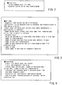
FIG. 3 is a figure illustrating set items used in the robot maintenance assist device inFIG. 1 . -
FIG. 4 is a figure illustrating each item of a trend graph prepared in the robot maintenance assist device inFIG. 1 . -
FIG. 5 is a figure illustrating an example of the trend graph prepared in the robot maintenance assist device inFIG. 1 . -
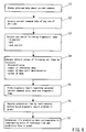
FIG. 6 is a flow chart illustrating a method of predicting a residual life of a robot drive system using the robot maintenance assist device inFIG. 1 . - Hereunder, a robot maintenance assist device according to one embodiment of the present invention will be described referring to the drawings.
- First of all, a schematic configuration of a robot which is an object of the robot maintenance assist device according to this embodiment will be described. The robot comprises a robot arm and a robot drive system for driving this robot arm and an external axis of the robot.
- The robot drive system has a servo motor generating drive force, a reduction gear transmitting drive force from the servo motor to the robot arm and the robot external axis, and an encoder detecting a position of the servo motor. The robot drive system is controlled by a servo control system including a position loop, a velocity loop, and a current loop.
- The robot which is an object of the robot maintenance assist device according to this embodiment comprises a robot drive system R1 having eight drive axes JT1 ~ JT8 as illustrated in
FIG. 1 , and this robot drive system R1 is controlled by a robot controller R2. - Further, a robot
maintenance assist device 1 according to this embodiment is a device for predicting life of the robot drive system R1 so as to assist maintenance. - As illustrated in
FIG. 1 , the robotmaintenance assist device 1 comprises adata acquiring unit 2 for acquiring data about current command value of each servo motor corresponding to each drive axis JT1 ~ JT8 of the robot drive system R1. - As for data acquisition by the
data acquiring unit 2, data may be acquired from the robot controller R2 via a communication line such as internet or data may be directly acquired from the robot controller R2 by connecting a substrate for data acquisition to the robot controller R2. - Data about current command value acquired by the
data acquiring unit 2 is sent to an acquireddata storing unit 4 configured in a PC 3 and stored there. The acquireddata storing unit 4 stores data about a plurality of current command values related to a plurality of servo motors configuring the robot drive system R1. - The robot
maintenance assist device 1 further comprises atendency diagnosis unit 5 for diagnosing future changing tendency of current command values of the servo motors. This tendency diagnosis unit 5 diagnoses future changing tendency of current command values based on data about current command values stored in the acquireddata storing unit 4. The diagnosis result can be output as a trend graph, for example. - The robot
maintenance assist device 1 further comprises alife determining unit 6 for determining life of the robot drive system R1. Thislife determining unit 6 determines a term until a current command value of the servo motor configuring the robot drive system R1 reaches a previously set value based on the future changing tendency of current command values acquired by thetendency diagnosis unit 5. - The robot
maintenance assist device 1 further comprises an object dataselect unit 7 for selecting a current command value to be diagnosed by thetendency diagnosis unit 5 from a plurality of current command values corresponding to each drive axis JT1 ~ JT8. Thus, the object data selectunit 7 can select a drive axis JT1 ~ JT8 whose residual life should be determined. - As illustrated in
FIG. 2 , the object data selected by the object dataselect unit 7 is data in an execution section set by a robot teach program. Thus, only data about current command values during robot operation is to be diagnosed and data during robot stopping is not to be diagnosed. Thereby, accuracy of determination of residual life can be improved. - The
tendency diagnosis unit 5 of the robotmaintenance assist device 1 has a function of making adisplay unit 8 display a prediction line representing future changing tendency of a current command value as a graph (trend graph). Further, thelife determining unit 6 is configured to determine a time point corresponding to an intersecting point of a prediction line displayed in the graph and a reference line set in the graph as a predicted life. - The robot
maintenance assist device 1 further comprises a diagnostic itemselect unit 9 for selecting a diagnostic item of current command value to be diagnosed by thetendency diagnosis unit 5 from an I2 monitor, duty (DUTY), and peak current. - As illustrated in
FIG. 3 , in the I2 monitor, an initial measured value is a reference and a threshold value is 107% (design criteria). In the DUTY, a motor continuous stall current value (motor manufacturer's specification) is a reference. In the peak current value, a current limit value (amplifier, reduction gear, current limit of motor) is a reference. - Additionally, the robot
maintenance assist device 1 comprises a setvalue change unit 10 for changing a set value used upon the diagnosis in thetendency diagnosis unit 5. As illustrated inFIG. 3 , set values used upon the diagnosis in thetendency diagnosis unit 5 include a threshold value regarding the current command value, the number of object data days (number of referenced days) from a current date, the number of days (number of days until determination) from the current date up to a determination date (life prediction value), and the lowest number of data used for diagnostic operation. - A graph displayed in the
display unit 8 of the robotmaintenance assist device 1 includes items shown inFIG. 4 and an example of the graph is illustrated inFIG. 5 . InFIG. 5 , in a case when the I2 monitor is selected in a diagnostic itemselect portion 11, a diagnosis result of the current command value regarding the servo motor corresponding to the drive axis JT1 selected in an object data selectportion 12 is illustrated. - A X axis (horizontal axis) of the graph illustrated in
FIG. 5 represents date and time when the data of the current command value is acquired and a Y axis (vertical axis) represents the current command value of the servo motor corresponding to the drive axis JT1, provided that the 12 monitor is a diagnostic item. The number of referenced days in the graph is 10 days which is a default. Areference line 13 to be a determination reference of a residual life is determined as the reference value * the threshold value / 100. - In the graph, a
prediction line 15 acquired by the least-squares method based on aplot data 14 of the current command value is shown. An intersecting point of thisprediction line 15 and thereference line 13 is shown as a prediction date 16 of a residual life. - Next, a method of predicting life of the robot drive system R1 so as to assist maintenance of the robot using the above-mentioned robot
maintenance assist device 1 will be described referring toFIG. 6 . - First, data about the current command values of the servo motors corresponding to a plurality of drive axes JT1 ∼ JT8 acquired by the
data acquiring unit 2 is stored by the acquired data storing unit 4 (acquired data storing process S1). Subsequently, the current command value to be diagnosed is selected from a plurality of current command values corresponding to a plurality of drive axes JT1 ∼ JT8 (object data select process S2). - Next, a diagnostic item is selected from the I2 monitor, DUTY, and peak current by the diagnostic item select unit 9 (diagnostic item select process S3). Further, default values of the threshold value, number of referenced days, number of days until determination, and number of data are changed by the set
value change unit 10 as necessary (set value change process S4). - Next, diagnosis results regarding the selected current command value data and diagnostic items are plotted in a graph by the tendency diagnosis unit 5 (diagnosis result plot process S5). Subsequently, a prediction line is depicted by the least-squares method based the diagnosis results plotted in the graph (prediction line depicting process S6). The diagnosis result plot process S5 and the prediction line depicting process S6 configure a tendency diagnosis process for diagnosing future changing tendency of the current command value.
- Next, the
life determining unit 6 determines a term until the current command value reaches the previously setreference line 13 based on the future changing tendency of the current command value acquired in the tendency diagnosis process S5, S6 (life determining process S7). Thus, in the life determining process S7, an intersecting point of theprediction line 15 displayed in the graph inFIG. 5 and thereference line 13 set in the graph is determined as a predicted life. - As stated above, according to this embodiment, a residual life of the robot drive system R1 can be predicted at high accuracy based on the data of the current command value of the servo motor of the robot drive system R1. Thereby, maintenance of the robot can be performed in a timely manner, and stop time of the robot due to breakdown can be minimized so that decline in productivity of the production line where the robot is installed can be surely prevented.
- Particularly, in this embodiment, the
tendency diagnosis unit 5 performs diagnosis based on only the current command value during robot operation, and therefore prediction accuracy of residual life of the robot drive system R1 can be further enhanced. - As another embodiment of the present invention, in the above-stated configuration of the embodiment, a device connectable to the PC3 connected to the robot controller R2 via a communication network such as internet can be installed in addition to or instead of the
display unit 8 connected to the robot controller R2. - A so-called smart device such as a tablet terminal, smartphone, and laptop PC is suitable for such a device. Alternatively, a common desktop PC also can be used. Thus, any device may be employed as long as it is connectable to the
PC 3 via a communication network in a place away from the site where the robot is installed. - In the robot maintenance assist device and method according to this embodiment, the robot condition can be remotely confirmed even in a place away from the site where the robot is installed. Thereby, the maintenance work of the robot can be performed more properly and timely.
-
- 1 ... robot maintenance assist device
- 2 ... data acquiring unit
- 3 ... PC
- 4 ... acquired data storing unit
- 5 ... tendency diagnosis unit
- 6 .. life determining unit
- 7 ... object data select unit
- 8 ... display unit
- 9 ... diagnostic item select unit
- 10 ... set value change unit
- 11 ... diagnostic item select portion
- 12 ... object data select portion
- 13 ... reference line of graph
- 14 ... plot data
- 15 ... prediction line of graph
- 16... prediction date of residual life
- R1... robot drive system
- R2... robot controller
- S1... acquired data storing process
- S2... object data select process
- S3 ... diagnostic item select process
- S4 ... set value change process
- S5 ... diagnosis result plot process (tendency diagnosis process)
- S6 ... prediction line depicting process (tendency diagnosis process)
- S7 ... life determining process
Claims (17)
- A robot maintenance assist device for predicting a life of a drive system of a robot so as to assist a maintenance, comprising:an acquired data storing unit for storing an acquired data about a current command value of a servo motor configuring the drive system of the robot;a tendency diagnosis unit for diagnosing a future changing tendency of the current command value based on the data of the current command value stored in the acquired data storing unit; anda life determining unit for determining a term until the current command value reaches a previously set value based on the future changing tendency of the current command value acquired by the tendency diagnosis unit.
- The robot maintenance assist device according to claim 1,
wherein the acquired data storing unit stores data about a plurality of current command values about a plurality of servo motors configuring the drive system of the robot, and
wherein the robot maintenance assist device further comprises an object data select unit for selecting the current command value to be diagnosed by the tendency diagnosis unit from the plurality of current command values. - The robot maintenance assist device according to claim 1 or 2, wherein the tendency diagnosis unit has a function of making a display unit display a prediction line representing the future changing tendency of the current command value as a graph.
- The robot maintenance assist device according to claim 3, wherein the life determining unit is configured to determine a time point corresponding to an intersecting point of the prediction line displayed in the graph and a reference line set in the graph as a predicted life.
- The robot maintenance assist device according to any one of claims 1 to 4, further comprising a diagnostic item select unit for selecting a diagnostic item of the current command value to be diagnosed by the tendency diagnosis unit from an I2 monitor, a DUTY, and a peak current.
- The robot maintenance assist device according to any one of claims 1 to 5, further comprising a set value change unit for changing a set value used upon a diagnosis in the tendency diagnosis unit.
- The robot maintenance assist device according to any one of claims 1 to 6, wherein the set value used upon a diagnosis in the tendency diagnosis unit includes at least one of a threshold value regarding the current command value, a number of object data days from a current date, a number of days from the current date up to a determination date, and a lowest number of data used for a diagnostic operation.
- The robot maintenance assist device according to any one of claims 1 to 7, wherein the tendency diagnosis unit is configured to perform a diagnosis based on only the current command value during an operation of the robot.
- A robot maintenance assist device for predicting a life of a drive system of a robot so as to assist a maintenance, comprising:an acquired data storing unit for storing an acquired data about a current command value of a servo motor configuring the drive system of the robot;a tendency diagnosis unit for diagnosing a future changing tendency of the current command value based on the data of the current command value stored in the acquired data storing unit;a life determining unit for determining a term until the current command value reaches a previously set value based on the future changing tendency of the current command value acquired by the tendency diagnosis unit; anda display unit for acquiring at least one of a diagnosis result of the tendency diagnosis unit and a determination result of the life determining unit via a communication network and displaying the diagnosis result and/or the determination result.
- A robot maintenance assist method for predicting a life of a drive system of a robot so as to assist a maintenance, comprising:an acquired data storing process of storing an acquired data about a current command value of a servo motor configuring the drive system of the robot;a tendency diagnosis process of diagnosing a future changing tendency of the current command value based on the data of the current command value stored by the acquired data storing process; anda life determining process for determining a term until the current command value reaches a previously set value based on the future changing tendency of the current command value acquired by the tendency diagnosis process.
- The robot maintenance assist method according to claim 10,
wherein, in the acquired data storing process, the data about a plurality of current command values about a plurality of servo motors configuring the drive system of the robot is stored, and
wherein the robot maintenance assist method further comprises an object data select process for selecting the current command value to be diagnosed in the tendency diagnosis process from the plurality of current command values. - The robot maintenance assist method according to claim 10 or 11, wherein, in the tendency diagnosis process, a prediction line representing the future changing tendency of the current command value is displayed as a graph on a display unit.
- The robot maintenance assist method according to claim 12, wherein, in the life determining process, a time point corresponding to an intersecting point of the prediction line displayed in the graph and a reference line set in the graph is determined as a predicted life.
- The robot maintenance assist method according to any one of claims 10 to 13, further comprising a diagnostic item select process for selecting a diagnostic item of the current command value to be diagnosed by the tendency diagnosis process from an I2 monitor, a DUTY, and a peak current.
- The robot maintenance assist method according to any one of claims 10 to 14, further comprising a set value change process for changing a set value used upon a diagnosis in the tendency diagnosis process.
- The robot maintenance assist method according to any one of claims 10 to 15, wherein the set value used upon a diagnosis in the tendency diagnosis process includes at least one of a threshold value regarding the current command value, a number of object data days from a current date, a number of days from the current date up to a determination date, and a lowest number of data used for a diagnostic operation.
- The robot maintenance assist method according to any one of claims 10 to 16, wherein, in the tendency diagnosis process, a diagnosis is performed based on only the current command value during an operation of the robot.
Applications Claiming Priority (3)
| Application Number | Priority Date | Filing Date | Title |
|---|---|---|---|
| JP2014257004 | 2014-12-19 | ||
| JP2015131422A JP6664893B2 (en) | 2014-12-19 | 2015-06-30 | Robot maintenance support device and method |
| PCT/JP2015/083652 WO2016098571A1 (en) | 2014-12-19 | 2015-11-30 | Robot maintenance assist device and method |
Publications (3)
| Publication Number | Publication Date |
|---|---|
| EP3235611A1 true EP3235611A1 (en) | 2017-10-25 |
| EP3235611A4 EP3235611A4 (en) | 2018-08-22 |
| EP3235611B1 EP3235611B1 (en) | 2023-03-22 |
Family
ID=56242672
Family Applications (1)
| Application Number | Title | Priority Date | Filing Date |
|---|---|---|---|
| EP15869779.7A Active EP3235611B1 (en) | 2014-12-19 | 2015-11-30 | Robot maintenance assist device and method |
Country Status (8)
| Country | Link |
|---|---|
| US (1) | US20170351243A1 (en) |
| EP (1) | EP3235611B1 (en) |
| JP (1) | JP6664893B2 (en) |
| KR (1) | KR20170093908A (en) |
| CN (2) | CN113664824A (en) |
| CA (1) | CA2971378C (en) |
| SG (1) | SG11201705045XA (en) |
| TW (1) | TWI603826B (en) |
Cited By (1)
| Publication number | Priority date | Publication date | Assignee | Title |
|---|---|---|---|---|
| EP4190518A4 (en) * | 2020-07-28 | 2024-08-21 | Kawasaki Jukogyo Kabushiki Kaisha | CONDITION MONITORING DEVICE, CONDITION ANOMALY DETERMINATION METHOD AND CONDITION ANOMALY DETERMINATION PROGRAM |
Families Citing this family (17)
| Publication number | Priority date | Publication date | Assignee | Title |
|---|---|---|---|---|
| JP2016158751A (en) * | 2015-02-27 | 2016-09-05 | ソニー株式会社 | Actuator and medical support arm device |
| JP6285403B2 (en) * | 2015-11-30 | 2018-02-28 | ファナック株式会社 | Cell control device and production system for predicting failure of manufacturing machine |
| JP6581050B2 (en) * | 2016-08-24 | 2019-09-25 | 川崎重工業株式会社 | Robot remote monitoring system |
| JP6905224B2 (en) * | 2017-03-24 | 2021-07-21 | 学校法人福岡工業大学 | Tool wear estimation method |
| JP6812925B2 (en) * | 2017-08-01 | 2021-01-13 | トヨタ自動車株式会社 | Robot arm, iron powder amount estimation method and abnormality sign judgment system |
| US12029512B2 (en) | 2017-08-10 | 2024-07-09 | Intuitive Surgical Operations, Inc. | Increased usable instrument life in telesurgical systems |
| US11617628B2 (en) | 2017-08-10 | 2023-04-04 | Intuitive Surgical Operations, Inc. | Increased usable instrument life in telesurgical systems |
| JP6940820B2 (en) | 2018-05-08 | 2021-09-29 | オムロン株式会社 | Robot control device, maintenance management method, and maintenance management program |
| JP6909410B2 (en) | 2018-05-08 | 2021-07-28 | オムロン株式会社 | Robot control device, maintenance management method, and maintenance management program |
| JP7309344B2 (en) * | 2018-11-13 | 2023-07-18 | 川崎重工業株式会社 | FAILURE DIAGNOSIS DEVICE AND FAILURE DIAGNOSIS METHOD OF DRIVE MECHANISM, AND MACHINE DEVICE INCLUDING SAME FAILURE DIAGNOSIS DEVICE |
| CN110987416A (en) * | 2019-11-18 | 2020-04-10 | 埃夫特智能装备股份有限公司 | Method for detecting wear state of robot speed reducer |
| US11554490B2 (en) | 2020-12-09 | 2023-01-17 | Robert Bosch Gmbh | Monitoring real-time data of a robotic manipulator |
| JP7657621B2 (en) * | 2021-03-11 | 2025-04-07 | 川崎重工業株式会社 | ROBOT SYSTEM AND METHOD FOR ASSEMBLING ROBOT SYSTEM |
| WO2022210072A1 (en) | 2021-03-29 | 2022-10-06 | 川崎重工業株式会社 | Robot malfunction sign detection device and robot malfunction sign detection method |
| JP7869661B2 (en) * | 2022-01-28 | 2026-06-03 | 川崎重工業株式会社 | Robot diagnostic device, robot diagnostic method, and robot diagnostic program |
| CN115042227B (en) * | 2022-05-30 | 2025-09-19 | 广州风神汽车有限公司 | Method and device for maintaining speed reducer and storage medium |
| JPWO2024257160A1 (en) * | 2023-06-12 | 2024-12-19 |
Family Cites Families (16)
| Publication number | Priority date | Publication date | Assignee | Title |
|---|---|---|---|---|
| JP3357143B2 (en) * | 1993-09-30 | 2002-12-16 | ファナック株式会社 | Robot controller that monitors the load on the robot |
| JPH09311715A (en) * | 1996-05-22 | 1997-12-02 | Fanuc Ltd | Robot error history display method |
| ATE344388T1 (en) * | 1999-08-12 | 2006-11-15 | Perihelian Llc | DRIVE MADE OF A SHAPE MEMORY ALLOY AND CONTROL METHOD |
| JP2004020388A (en) * | 2002-06-17 | 2004-01-22 | Mitsubishi Electric Corp | Life evaluation device |
| JP2005148873A (en) * | 2003-11-12 | 2005-06-09 | Nachi Fujikoshi Corp | Robot degradation diagnosis device |
| JP4286171B2 (en) * | 2004-03-30 | 2009-06-24 | 三洋電機株式会社 | Equipment diagnostic device |
| US7222048B2 (en) * | 2005-04-21 | 2007-05-22 | General Electric Company | Methods and systems for diagnosing machinery |
| JP2007172150A (en) * | 2005-12-20 | 2007-07-05 | Honda Motor Co Ltd | Failure diagnosis method for industrial machinery |
| JP2007190663A (en) * | 2006-01-23 | 2007-08-02 | Seiko Epson Corp | Maintenance method and robot controller |
| EP1955830B1 (en) * | 2007-02-06 | 2014-04-09 | Abb Research Ltd. | A method and a control system for monitoring the condition of an industrial robot |
| US8773142B2 (en) * | 2009-06-26 | 2014-07-08 | Panasonic Corporation | Electronic part and method of detecting faults therein |
| DE102009035998A1 (en) * | 2009-07-27 | 2011-02-03 | Pilz Gmbh & Co. Kg | Method and device for fail-safe monitoring of a movement quantity on an electric drive |
| JP5365595B2 (en) * | 2010-09-15 | 2013-12-11 | 株式会社安川電機 | Speed reducer abnormality determination method, abnormality determination apparatus, robot, and robot system |
| US8712726B2 (en) * | 2010-12-01 | 2014-04-29 | Xerox Corporation | System and method for predicting remaining useful life of device components |
| JP2013231673A (en) * | 2012-04-27 | 2013-11-14 | Hitachi Constr Mach Co Ltd | Life prediction system of speed reducer gear of dump truck |
| JP5628953B2 (en) * | 2013-03-29 | 2014-11-19 | ファナック株式会社 | Articulated robot with gas spring and method for estimating internal pressure of gas spring |
-
2015
- 2015-06-30 JP JP2015131422A patent/JP6664893B2/en active Active
- 2015-11-30 KR KR1020177018647A patent/KR20170093908A/en not_active Ceased
- 2015-11-30 CN CN202110641591.0A patent/CN113664824A/en active Pending
- 2015-11-30 SG SG11201705045XA patent/SG11201705045XA/en unknown
- 2015-11-30 EP EP15869779.7A patent/EP3235611B1/en active Active
- 2015-11-30 CA CA2971378A patent/CA2971378C/en active Active
- 2015-11-30 CN CN201580069458.5A patent/CN107107348B/en active Active
- 2015-11-30 US US15/537,461 patent/US20170351243A1/en not_active Abandoned
- 2015-12-07 TW TW104140969A patent/TWI603826B/en active
Cited By (1)
| Publication number | Priority date | Publication date | Assignee | Title |
|---|---|---|---|---|
| EP4190518A4 (en) * | 2020-07-28 | 2024-08-21 | Kawasaki Jukogyo Kabushiki Kaisha | CONDITION MONITORING DEVICE, CONDITION ANOMALY DETERMINATION METHOD AND CONDITION ANOMALY DETERMINATION PROGRAM |
Also Published As
| Publication number | Publication date |
|---|---|
| EP3235611A4 (en) | 2018-08-22 |
| JP6664893B2 (en) | 2020-03-13 |
| CN113664824A (en) | 2021-11-19 |
| CN107107348A (en) | 2017-08-29 |
| TW201632327A (en) | 2016-09-16 |
| US20170351243A1 (en) | 2017-12-07 |
| KR20170093908A (en) | 2017-08-16 |
| CA2971378C (en) | 2020-12-08 |
| JP2016117148A (en) | 2016-06-30 |
| SG11201705045XA (en) | 2017-07-28 |
| CN107107348B (en) | 2021-10-26 |
| CA2971378A1 (en) | 2016-06-23 |
| EP3235611B1 (en) | 2023-03-22 |
| TWI603826B (en) | 2017-11-01 |
Similar Documents
| Publication | Publication Date | Title |
|---|---|---|
| CA2971378C (en) | Robot maintenance assist device and method | |
| JP7107830B2 (en) | Learning data confirmation support device, machine learning device, failure prediction device | |
| JP6451662B2 (en) | Abnormality determination device, abnormality determination program, abnormality determination system, and motor control device | |
| CN107614217B (en) | Fault diagnosis device and fault diagnosis method | |
| US20200061768A1 (en) | Information processing method, information processing system, and information processing device | |
| US10386816B2 (en) | Manufacturing management system for changing abnormality detection condition according to manufacturing period-of-time information | |
| US9471058B2 (en) | Data acquisition device for acquiring cause of stoppage of drive axis and information relating thereto | |
| EP3305482A1 (en) | Failure diagnosis device and failure diagnosis method | |
| EP2952869B1 (en) | Gear transmission and usage measuring device for measuring usage of gear transmission | |
| CN112673327A (en) | Control device and program | |
| US20150277443A1 (en) | Feedback control system having servomechanism monitoring system and methods of monitoring servomechanisms | |
| CN111164520A (en) | Mechanical equipment control system, mechanical equipment control device, and mechanical equipment control method | |
| TWI688459B (en) | Data collection system and method | |
| CN111989198B (en) | Abnormality detection device and abnormality detection method | |
| KR102397267B1 (en) | Robot maintenance assist device and method | |
| CN112867975B (en) | Maintenance support system, numerical control device, and method for controlling maintenance support system | |
| CN112005256B (en) | Maintenance record creation device and maintenance record creation method | |
| JP7228862B2 (en) | Machine diagnostic system and diagnostic program | |
| CN110091310A (en) | Robot and the notification method in the maintenance period about robot | |
| JP2007328431A (en) | Observation device of internal data of controller | |
| JP2009146020A (en) | Communications system for position detector | |
| CN108572623B (en) | Servo motor control unit and servo motor control system | |
| JP2020025461A (en) | Motor control system | |
| US20140156974A1 (en) | Device operating information providing device and device operating information providing method |
Legal Events
| Date | Code | Title | Description |
|---|---|---|---|
| STAA | Information on the status of an ep patent application or granted ep patent |
Free format text: STATUS: THE INTERNATIONAL PUBLICATION HAS BEEN MADE |
|
| PUAI | Public reference made under article 153(3) epc to a published international application that has entered the european phase |
Free format text: ORIGINAL CODE: 0009012 |
|
| STAA | Information on the status of an ep patent application or granted ep patent |
Free format text: STATUS: REQUEST FOR EXAMINATION WAS MADE |
|
| 17P | Request for examination filed |
Effective date: 20170713 |
|
| AK | Designated contracting states |
Kind code of ref document: A1 Designated state(s): AL AT BE BG CH CY CZ DE DK EE ES FI FR GB GR HR HU IE IS IT LI LT LU LV MC MK MT NL NO PL PT RO RS SE SI SK SM TR |
|
| AX | Request for extension of the european patent |
Extension state: BA ME |
|
| DAV | Request for validation of the european patent (deleted) | ||
| DAX | Request for extension of the european patent (deleted) | ||
| A4 | Supplementary search report drawn up and despatched |
Effective date: 20180720 |
|
| RIC1 | Information provided on ipc code assigned before grant |
Ipc: G05B 19/418 20060101ALI20180716BHEP Ipc: B25J 9/16 20060101ALI20180716BHEP Ipc: B25J 19/00 20060101AFI20180716BHEP Ipc: G05B 19/18 20060101ALI20180716BHEP Ipc: G05B 19/4065 20060101ALI20180716BHEP |
|
| STAA | Information on the status of an ep patent application or granted ep patent |
Free format text: STATUS: EXAMINATION IS IN PROGRESS |
|
| 17Q | First examination report despatched |
Effective date: 20210309 |
|
| GRAP | Despatch of communication of intention to grant a patent |
Free format text: ORIGINAL CODE: EPIDOSNIGR1 |
|
| STAA | Information on the status of an ep patent application or granted ep patent |
Free format text: STATUS: GRANT OF PATENT IS INTENDED |
|
| INTG | Intention to grant announced |
Effective date: 20221103 |
|
| GRAS | Grant fee paid |
Free format text: ORIGINAL CODE: EPIDOSNIGR3 |
|
| GRAA | (expected) grant |
Free format text: ORIGINAL CODE: 0009210 |
|
| STAA | Information on the status of an ep patent application or granted ep patent |
Free format text: STATUS: THE PATENT HAS BEEN GRANTED |
|
| AK | Designated contracting states |
Kind code of ref document: B1 Designated state(s): AL AT BE BG CH CY CZ DE DK EE ES FI FR GB GR HR HU IE IS IT LI LT LU LV MC MK MT NL NO PL PT RO RS SE SI SK SM TR |
|
| REG | Reference to a national code |
Ref country code: GB Ref legal event code: FG4D |
|
| REG | Reference to a national code |
Ref country code: CH Ref legal event code: EP |
|
| REG | Reference to a national code |
Ref country code: DE Ref legal event code: R096 Ref document number: 602015082907 Country of ref document: DE |
|
| REG | Reference to a national code |
Ref country code: IE Ref legal event code: FG4D |
|
| REG | Reference to a national code |
Ref country code: AT Ref legal event code: REF Ref document number: 1555006 Country of ref document: AT Kind code of ref document: T Effective date: 20230415 |
|
| REG | Reference to a national code |
Ref country code: LT Ref legal event code: MG9D |
|
| REG | Reference to a national code |
Ref country code: NL Ref legal event code: MP Effective date: 20230322 |
|
| PG25 | Lapsed in a contracting state [announced via postgrant information from national office to epo] |
Ref country code: RS Free format text: LAPSE BECAUSE OF FAILURE TO SUBMIT A TRANSLATION OF THE DESCRIPTION OR TO PAY THE FEE WITHIN THE PRESCRIBED TIME-LIMIT Effective date: 20230322 Ref country code: NO Free format text: LAPSE BECAUSE OF FAILURE TO SUBMIT A TRANSLATION OF THE DESCRIPTION OR TO PAY THE FEE WITHIN THE PRESCRIBED TIME-LIMIT Effective date: 20230622 Ref country code: LV Free format text: LAPSE BECAUSE OF FAILURE TO SUBMIT A TRANSLATION OF THE DESCRIPTION OR TO PAY THE FEE WITHIN THE PRESCRIBED TIME-LIMIT Effective date: 20230322 Ref country code: LT Free format text: LAPSE BECAUSE OF FAILURE TO SUBMIT A TRANSLATION OF THE DESCRIPTION OR TO PAY THE FEE WITHIN THE PRESCRIBED TIME-LIMIT Effective date: 20230322 Ref country code: HR Free format text: LAPSE BECAUSE OF FAILURE TO SUBMIT A TRANSLATION OF THE DESCRIPTION OR TO PAY THE FEE WITHIN THE PRESCRIBED TIME-LIMIT Effective date: 20230322 |
|
| REG | Reference to a national code |
Ref country code: AT Ref legal event code: MK05 Ref document number: 1555006 Country of ref document: AT Kind code of ref document: T Effective date: 20230322 |
|
| PG25 | Lapsed in a contracting state [announced via postgrant information from national office to epo] |
Ref country code: SE Free format text: LAPSE BECAUSE OF FAILURE TO SUBMIT A TRANSLATION OF THE DESCRIPTION OR TO PAY THE FEE WITHIN THE PRESCRIBED TIME-LIMIT Effective date: 20230322 Ref country code: NL Free format text: LAPSE BECAUSE OF FAILURE TO SUBMIT A TRANSLATION OF THE DESCRIPTION OR TO PAY THE FEE WITHIN THE PRESCRIBED TIME-LIMIT Effective date: 20230322 Ref country code: GR Free format text: LAPSE BECAUSE OF FAILURE TO SUBMIT A TRANSLATION OF THE DESCRIPTION OR TO PAY THE FEE WITHIN THE PRESCRIBED TIME-LIMIT Effective date: 20230623 Ref country code: FI Free format text: LAPSE BECAUSE OF FAILURE TO SUBMIT A TRANSLATION OF THE DESCRIPTION OR TO PAY THE FEE WITHIN THE PRESCRIBED TIME-LIMIT Effective date: 20230322 |
|
| PG25 | Lapsed in a contracting state [announced via postgrant information from national office to epo] |
Ref country code: SM Free format text: LAPSE BECAUSE OF FAILURE TO SUBMIT A TRANSLATION OF THE DESCRIPTION OR TO PAY THE FEE WITHIN THE PRESCRIBED TIME-LIMIT Effective date: 20230322 Ref country code: RO Free format text: LAPSE BECAUSE OF FAILURE TO SUBMIT A TRANSLATION OF THE DESCRIPTION OR TO PAY THE FEE WITHIN THE PRESCRIBED TIME-LIMIT Effective date: 20230322 Ref country code: PT Free format text: LAPSE BECAUSE OF FAILURE TO SUBMIT A TRANSLATION OF THE DESCRIPTION OR TO PAY THE FEE WITHIN THE PRESCRIBED TIME-LIMIT Effective date: 20230724 Ref country code: ES Free format text: LAPSE BECAUSE OF FAILURE TO SUBMIT A TRANSLATION OF THE DESCRIPTION OR TO PAY THE FEE WITHIN THE PRESCRIBED TIME-LIMIT Effective date: 20230322 Ref country code: EE Free format text: LAPSE BECAUSE OF FAILURE TO SUBMIT A TRANSLATION OF THE DESCRIPTION OR TO PAY THE FEE WITHIN THE PRESCRIBED TIME-LIMIT Effective date: 20230322 Ref country code: AT Free format text: LAPSE BECAUSE OF FAILURE TO SUBMIT A TRANSLATION OF THE DESCRIPTION OR TO PAY THE FEE WITHIN THE PRESCRIBED TIME-LIMIT Effective date: 20230322 |
|
| PG25 | Lapsed in a contracting state [announced via postgrant information from national office to epo] |
Ref country code: SK Free format text: LAPSE BECAUSE OF FAILURE TO SUBMIT A TRANSLATION OF THE DESCRIPTION OR TO PAY THE FEE WITHIN THE PRESCRIBED TIME-LIMIT Effective date: 20230322 Ref country code: PL Free format text: LAPSE BECAUSE OF FAILURE TO SUBMIT A TRANSLATION OF THE DESCRIPTION OR TO PAY THE FEE WITHIN THE PRESCRIBED TIME-LIMIT Effective date: 20230322 Ref country code: IS Free format text: LAPSE BECAUSE OF FAILURE TO SUBMIT A TRANSLATION OF THE DESCRIPTION OR TO PAY THE FEE WITHIN THE PRESCRIBED TIME-LIMIT Effective date: 20230722 |
|
| REG | Reference to a national code |
Ref country code: DE Ref legal event code: R097 Ref document number: 602015082907 Country of ref document: DE |
|
| PLBE | No opposition filed within time limit |
Free format text: ORIGINAL CODE: 0009261 |
|
| STAA | Information on the status of an ep patent application or granted ep patent |
Free format text: STATUS: NO OPPOSITION FILED WITHIN TIME LIMIT |
|
| PG25 | Lapsed in a contracting state [announced via postgrant information from national office to epo] |
Ref country code: SI Free format text: LAPSE BECAUSE OF FAILURE TO SUBMIT A TRANSLATION OF THE DESCRIPTION OR TO PAY THE FEE WITHIN THE PRESCRIBED TIME-LIMIT Effective date: 20230322 Ref country code: DK Free format text: LAPSE BECAUSE OF FAILURE TO SUBMIT A TRANSLATION OF THE DESCRIPTION OR TO PAY THE FEE WITHIN THE PRESCRIBED TIME-LIMIT Effective date: 20230322 Ref country code: CZ Free format text: LAPSE BECAUSE OF FAILURE TO SUBMIT A TRANSLATION OF THE DESCRIPTION OR TO PAY THE FEE WITHIN THE PRESCRIBED TIME-LIMIT Effective date: 20230322 |
|
| 26N | No opposition filed |
Effective date: 20240102 |
|
| PG25 | Lapsed in a contracting state [announced via postgrant information from national office to epo] |
Ref country code: IT Free format text: LAPSE BECAUSE OF FAILURE TO SUBMIT A TRANSLATION OF THE DESCRIPTION OR TO PAY THE FEE WITHIN THE PRESCRIBED TIME-LIMIT Effective date: 20230322 |
|
| REG | Reference to a national code |
Ref country code: CH Ref legal event code: PL |
|
| PG25 | Lapsed in a contracting state [announced via postgrant information from national office to epo] |
Ref country code: MC Free format text: LAPSE BECAUSE OF FAILURE TO SUBMIT A TRANSLATION OF THE DESCRIPTION OR TO PAY THE FEE WITHIN THE PRESCRIBED TIME-LIMIT Effective date: 20230322 |
|
| PG25 | Lapsed in a contracting state [announced via postgrant information from national office to epo] |
Ref country code: LU Free format text: LAPSE BECAUSE OF NON-PAYMENT OF DUE FEES Effective date: 20231130 |
|
| PG25 | Lapsed in a contracting state [announced via postgrant information from national office to epo] |
Ref country code: CH Free format text: LAPSE BECAUSE OF NON-PAYMENT OF DUE FEES Effective date: 20231130 |
|
| GBPC | Gb: european patent ceased through non-payment of renewal fee |
Effective date: 20231130 |
|
| PG25 | Lapsed in a contracting state [announced via postgrant information from national office to epo] |
Ref country code: MC Free format text: LAPSE BECAUSE OF FAILURE TO SUBMIT A TRANSLATION OF THE DESCRIPTION OR TO PAY THE FEE WITHIN THE PRESCRIBED TIME-LIMIT Effective date: 20230322 Ref country code: LU Free format text: LAPSE BECAUSE OF NON-PAYMENT OF DUE FEES Effective date: 20231130 Ref country code: CH Free format text: LAPSE BECAUSE OF NON-PAYMENT OF DUE FEES Effective date: 20231130 |
|
| REG | Reference to a national code |
Ref country code: BE Ref legal event code: MM Effective date: 20231130 |
|
| REG | Reference to a national code |
Ref country code: IE Ref legal event code: MM4A |
|
| PG25 | Lapsed in a contracting state [announced via postgrant information from national office to epo] |
Ref country code: IE Free format text: LAPSE BECAUSE OF NON-PAYMENT OF DUE FEES Effective date: 20231130 |
|
| PG25 | Lapsed in a contracting state [announced via postgrant information from national office to epo] |
Ref country code: GB Free format text: LAPSE BECAUSE OF NON-PAYMENT OF DUE FEES Effective date: 20231130 |
|
| PG25 | Lapsed in a contracting state [announced via postgrant information from national office to epo] |
Ref country code: BE Free format text: LAPSE BECAUSE OF NON-PAYMENT OF DUE FEES Effective date: 20231130 |
|
| PG25 | Lapsed in a contracting state [announced via postgrant information from national office to epo] |
Ref country code: FR Free format text: LAPSE BECAUSE OF NON-PAYMENT OF DUE FEES Effective date: 20231130 |
|
| PG25 | Lapsed in a contracting state [announced via postgrant information from national office to epo] |
Ref country code: IE Free format text: LAPSE BECAUSE OF NON-PAYMENT OF DUE FEES Effective date: 20231130 Ref country code: GB Free format text: LAPSE BECAUSE OF NON-PAYMENT OF DUE FEES Effective date: 20231130 Ref country code: FR Free format text: LAPSE BECAUSE OF NON-PAYMENT OF DUE FEES Effective date: 20231130 Ref country code: BE Free format text: LAPSE BECAUSE OF NON-PAYMENT OF DUE FEES Effective date: 20231130 |
|
| PG25 | Lapsed in a contracting state [announced via postgrant information from national office to epo] |
Ref country code: BG Free format text: LAPSE BECAUSE OF FAILURE TO SUBMIT A TRANSLATION OF THE DESCRIPTION OR TO PAY THE FEE WITHIN THE PRESCRIBED TIME-LIMIT Effective date: 20230322 |
|
| PG25 | Lapsed in a contracting state [announced via postgrant information from national office to epo] |
Ref country code: BG Free format text: LAPSE BECAUSE OF FAILURE TO SUBMIT A TRANSLATION OF THE DESCRIPTION OR TO PAY THE FEE WITHIN THE PRESCRIBED TIME-LIMIT Effective date: 20230322 |
|
| PG25 | Lapsed in a contracting state [announced via postgrant information from national office to epo] |
Ref country code: CY Free format text: LAPSE BECAUSE OF FAILURE TO SUBMIT A TRANSLATION OF THE DESCRIPTION OR TO PAY THE FEE WITHIN THE PRESCRIBED TIME-LIMIT; INVALID AB INITIO Effective date: 20151130 |
|
| PG25 | Lapsed in a contracting state [announced via postgrant information from national office to epo] |
Ref country code: HU Free format text: LAPSE BECAUSE OF FAILURE TO SUBMIT A TRANSLATION OF THE DESCRIPTION OR TO PAY THE FEE WITHIN THE PRESCRIBED TIME-LIMIT; INVALID AB INITIO Effective date: 20151130 |
|
| PG25 | Lapsed in a contracting state [announced via postgrant information from national office to epo] |
Ref country code: TR Free format text: LAPSE BECAUSE OF FAILURE TO SUBMIT A TRANSLATION OF THE DESCRIPTION OR TO PAY THE FEE WITHIN THE PRESCRIBED TIME-LIMIT Effective date: 20230322 |
|
| PGFP | Annual fee paid to national office [announced via postgrant information from national office to epo] |
Ref country code: DE Payment date: 20250930 Year of fee payment: 11 |