EP3235583B1 - Combined blade clamp and tensioner for scroll saw - Google Patents
Combined blade clamp and tensioner for scroll saw Download PDFInfo
- Publication number
- EP3235583B1 EP3235583B1 EP17165726.5A EP17165726A EP3235583B1 EP 3235583 B1 EP3235583 B1 EP 3235583B1 EP 17165726 A EP17165726 A EP 17165726A EP 3235583 B1 EP3235583 B1 EP 3235583B1
- Authority
- EP
- European Patent Office
- Prior art keywords
- clamp
- lever
- blade
- axis
- along
- Prior art date
- Legal status (The legal status is an assumption and is not a legal conclusion. Google has not performed a legal analysis and makes no representation as to the accuracy of the status listed.)
- Active
Links
Images


Classifications
-
- B—PERFORMING OPERATIONS; TRANSPORTING
- B27—WORKING OR PRESERVING WOOD OR SIMILAR MATERIAL; NAILING OR STAPLING MACHINES IN GENERAL
- B27B—SAWS FOR WOOD OR SIMILAR MATERIAL; COMPONENTS OR ACCESSORIES THEREFOR
- B27B19/00—Other reciprocating saws with power drive; Fret-saws
- B27B19/02—Saws with a power- driven blade chucked at both ends or at one end only, e.g. jig saws, scroll saws
-
- B—PERFORMING OPERATIONS; TRANSPORTING
- B23—MACHINE TOOLS; METAL-WORKING NOT OTHERWISE PROVIDED FOR
- B23D—PLANING; SLOTTING; SHEARING; BROACHING; SAWING; FILING; SCRAPING; LIKE OPERATIONS FOR WORKING METAL BY REMOVING MATERIAL, NOT OTHERWISE PROVIDED FOR
- B23D51/00—Sawing machines or sawing devices working with straight blades, characterised only by constructional features of particular parts; Carrying or attaching means for tools, covered by this subclass, which are connected to a carrier at both ends
- B23D51/08—Sawing machines or sawing devices working with straight blades, characterised only by constructional features of particular parts; Carrying or attaching means for tools, covered by this subclass, which are connected to a carrier at both ends of devices for mounting straight saw blades or other tools
- B23D51/12—Sawing machines or sawing devices working with straight blades, characterised only by constructional features of particular parts; Carrying or attaching means for tools, covered by this subclass, which are connected to a carrier at both ends of devices for mounting straight saw blades or other tools for use with tools, dealt with in this subclass, which are connected to a carrier at both ends, e.g. bows adjustable in length or height
- B23D51/125—Blade tensioning means
-
- B—PERFORMING OPERATIONS; TRANSPORTING
- B23—MACHINE TOOLS; METAL-WORKING NOT OTHERWISE PROVIDED FOR
- B23D—PLANING; SLOTTING; SHEARING; BROACHING; SAWING; FILING; SCRAPING; LIKE OPERATIONS FOR WORKING METAL BY REMOVING MATERIAL, NOT OTHERWISE PROVIDED FOR
- B23D57/00—Sawing machines or sawing devices not covered by one of the preceding groups B23D45/00 - B23D55/00
- B23D57/003—Sawing machines or sawing devices working with saw wires, characterised only by constructional features of particular parts
-
- B—PERFORMING OPERATIONS; TRANSPORTING
- B23—MACHINE TOOLS; METAL-WORKING NOT OTHERWISE PROVIDED FOR
- B23D—PLANING; SLOTTING; SHEARING; BROACHING; SAWING; FILING; SCRAPING; LIKE OPERATIONS FOR WORKING METAL BY REMOVING MATERIAL, NOT OTHERWISE PROVIDED FOR
- B23D49/00—Machines or devices for sawing with straight reciprocating saw blades, e.g. hacksaws
- B23D49/007—Jig saws, i.e. machine saws with a vertically reciprocating narrow saw blade chucked at both ends for contour cutting
-
- B—PERFORMING OPERATIONS; TRANSPORTING
- B23—MACHINE TOOLS; METAL-WORKING NOT OTHERWISE PROVIDED FOR
- B23D—PLANING; SLOTTING; SHEARING; BROACHING; SAWING; FILING; SCRAPING; LIKE OPERATIONS FOR WORKING METAL BY REMOVING MATERIAL, NOT OTHERWISE PROVIDED FOR
- B23D51/00—Sawing machines or sawing devices working with straight blades, characterised only by constructional features of particular parts; Carrying or attaching means for tools, covered by this subclass, which are connected to a carrier at both ends
- B23D51/02—Sawing machines or sawing devices working with straight blades, characterised only by constructional features of particular parts; Carrying or attaching means for tools, covered by this subclass, which are connected to a carrier at both ends of beds; of guiding arrangements for work-tables or saw carriers; of frames
-
- B—PERFORMING OPERATIONS; TRANSPORTING
- B23—MACHINE TOOLS; METAL-WORKING NOT OTHERWISE PROVIDED FOR
- B23D—PLANING; SLOTTING; SHEARING; BROACHING; SAWING; FILING; SCRAPING; LIKE OPERATIONS FOR WORKING METAL BY REMOVING MATERIAL, NOT OTHERWISE PROVIDED FOR
- B23D51/00—Sawing machines or sawing devices working with straight blades, characterised only by constructional features of particular parts; Carrying or attaching means for tools, covered by this subclass, which are connected to a carrier at both ends
- B23D51/08—Sawing machines or sawing devices working with straight blades, characterised only by constructional features of particular parts; Carrying or attaching means for tools, covered by this subclass, which are connected to a carrier at both ends of devices for mounting straight saw blades or other tools
- B23D51/12—Sawing machines or sawing devices working with straight blades, characterised only by constructional features of particular parts; Carrying or attaching means for tools, covered by this subclass, which are connected to a carrier at both ends of devices for mounting straight saw blades or other tools for use with tools, dealt with in this subclass, which are connected to a carrier at both ends, e.g. bows adjustable in length or height
- B23D51/14—Attachment of the tool
-
- B—PERFORMING OPERATIONS; TRANSPORTING
- B23—MACHINE TOOLS; METAL-WORKING NOT OTHERWISE PROVIDED FOR
- B23D—PLANING; SLOTTING; SHEARING; BROACHING; SAWING; FILING; SCRAPING; LIKE OPERATIONS FOR WORKING METAL BY REMOVING MATERIAL, NOT OTHERWISE PROVIDED FOR
- B23D57/00—Sawing machines or sawing devices not covered by one of the preceding groups B23D45/00 - B23D55/00
- B23D57/003—Sawing machines or sawing devices working with saw wires, characterised only by constructional features of particular parts
- B23D57/0069—Sawing machines or sawing devices working with saw wires, characterised only by constructional features of particular parts of devices for tensioning saw wires
-
- B—PERFORMING OPERATIONS; TRANSPORTING
- B23—MACHINE TOOLS; METAL-WORKING NOT OTHERWISE PROVIDED FOR
- B23D—PLANING; SLOTTING; SHEARING; BROACHING; SAWING; FILING; SCRAPING; LIKE OPERATIONS FOR WORKING METAL BY REMOVING MATERIAL, NOT OTHERWISE PROVIDED FOR
- B23D59/00—Accessories specially designed for sawing machines or sawing devices
- B23D59/006—Accessories specially designed for sawing machines or sawing devices for removing or collecting chips
-
- B—PERFORMING OPERATIONS; TRANSPORTING
- B27—WORKING OR PRESERVING WOOD OR SIMILAR MATERIAL; NAILING OR STAPLING MACHINES IN GENERAL
- B27B—SAWS FOR WOOD OR SIMILAR MATERIAL; COMPONENTS OR ACCESSORIES THEREFOR
- B27B29/00—Gripping, clamping, or holding devices for the trunk or log in saw mills or sawing machines; Travelling trunk or log carriages
- B27B29/02—Clamping angles; Gripping equipment thereon
Definitions
- Embodiments described herein generally relate to a saw, including a scroll saw having a blade clamp to secure a cutting blade of the scroll saw.
- Scroll saws include first and second arms that hold a cutting blade and reciprocate in unison to move the cutting blade in a reciprocating motion as an object to be cut is brought into contact with the moving blade. In operation, the blade is under tension while being used. The blade is removable from and replaceable on the first and the second arms which hold the cutting blade.
- Scroll saws may be used to cut wood, metal or other materials.
- a scroll saw blade is typically relatively fine compared to blades used in band saws or jigsaws, for example, permitting the scroll saw to be used to make intricate curved cuts in the material, such as to form scrollwork or other finely curved cuts.
- the blade may be removed from the arms of the scroll and placed through a pre-drilled starting hole in the material before remounting on the arms, allowing interior cuts to be made without requiring an entry slot to the interior cut.
- Another example is known from US2016045963A1 .
- FIG. 1A illustrates a scroll saw 100 according to an exemplary embodiment of the present disclosure.
- the scroll saw 100 includes a worktable 102 mounted on a base 104.
- a cutting blade 116 extends through an aperture 117 (see FIG. 1B ) of the worktable 102 and is secured between an upper blade clamp 120 and a lower blade clamp 112.
- the cutting blade 116 extends substantially vertically between the upper blade clamp 120 and the lower plate clamp 112.
- the cutting blade 116 and the worktable 102 may be positioned substantially orthogonal to each other, but may be adjusted to other angles by the user as desired. For example, an angle of the cutting blade 116 can be adjusted with respect to the worktable 102 and/or an angle of the worktable can be adjusted with respect to the cutting blade 116.
- a bevel adjustment 122 can be configured to adjust an angle of the worktable 102 with respect to the cutting blade 116 by tilting the worktable 102 as the bevel adjustment 122 moves along the semicircular bracket marked with angle indicia.
- the bevel adjustment 122 can be configured to adjust an angle of the cutting blade 116 by tilting the upper and lower blade clamps 120, 112 with respect to the worktable 102 as a bevel adjustment 122 moves along the semicircular bracket.
- the upper blade clamp 120 is supported by an upper arm 114 and the lower blade clamp 112 is supported by a lower arm 110.
- the upper arm 114 and the lower arm 110 reciprocate in unison to move the cutting blade 116 along an axis formed between the upper blade clamp 120 and the lower blade clamp 112.
- the cutting blade 116 is in a vertical arrangement and the reciprocation of the upper blade clamp 120 and the lower blade clamp 112 moves the cutting blade 116 in an up and down motion.
- the upper arm 114 supports the upper blade clamp 120 on a first end of the upper arm 114.
- the blade clamp 120 may include a head 144 that supports a clamp 142 that engages and secures the cutting blade 116.
- the blade clamp 120 can include a lever 140 that is configured to adjust the position of the clamp 142 based on the position of the lever 140.
- a second end of the upper arm 114 opposite the first end is connected to an upper support member 106.
- the upper support member 106 is further connected to a reciprocation mechanism (not shown) of a type that is known in the art and that is driven by a motor 134.
- the lower support member 110 supports the lower blade clamp 112 on a first end of the lower support member 110.
- a second end opposite the first end is connected to a lower support member 108.
- the lower support member 108 is further connected to the reciprocation mechanism that is driven by the motor 134.
- the reciprocation mechanism may be any mechanism as would be understood by one of ordinary skill that is configured to move the support members 106 and 108 in a reciprocating motion. In operation, the reciprocation mechanism moves the support members 106 and 108 in a reciprocating motion which causes the upper arm 114 and the lower arm 110 to move in the reciprocating motion.
- the scroll saw 100 can also include a dust blower 118 configured to expel air or other gas near a cutting zone of the cutting blade 116 to blow and remove waste (e.g. sawdust) generated by the cutting blade 116 as the cutting blade 116 cuts a workpiece such as a piece of wood.
- a vacuum or dust collecting system may be connected to collect dust and debris in certain embodiments.
- the scroll saw 100 can be powered by, for example, an electric power source (e.g. an AC or DC power outlet and/or DC battery) and can be connected to the electrical power source by a power cord 124.
- the power source is not limited to electric power sources and the scroll saw 100 can be powered by other power sources, such as steam or manpower through a crank or other means.
- a powered scroll saw is illustrated, the present blade clamp may be used on a variety of manual and powered saws.
- the scroll saw 100 can include one or more tension adjustments 130, 132 that can adjust the tension force applied to the cutting blade 116 by the blade clamps 120 and 112.
- the tension adjustments 130, 132 can adjust a distance between the blade clamp 120 and the lower blade clamp 112 to adjust for different blade lengths or to adjust the tension force applied to the cutting blade 116.
- the scroll saw 100 can include a foot and arm 126 that can be lowered onto a workpiece to secure the workpiece on the worktable 102 and/or to serve as a location reference or guide.
- the foot and arm 126 includes an arm to which is attached a U-shaped foot that may have location marks on either side of the blade, as shown.
- the blade clamp 120 is shown, illustrating the components of the blade clamp 120 as mounted on the saw.
- the dust blower 118 includes a nozzle 128 that directs a stream of air toward the cutting area.
- the nozzle 128 is mounted on a flexible hose and may be directed as desired or may be moved out of the way.
- the cutting blade 116 is held in the clamp 142 by compression exerted on opposite sides of the clamp 142 to roller assemblies or compression member assemblies 148, depending on the position of the lever 140.
- FIG. 2 illustrates an exploded view of the blade clamp 120 according to an exemplary embodiment of the present disclosure, for example, as may be mounted on the saw 100 in FIGS. 1A and 1B .
- the blade clamp 120 may include a head 144 that supports a clamp 142 which engages and secures the cutting blade 116.
- the blade clamp 120 may include a lever 140 that is configured to adjust the position of the clamp 142 based on the position of the lever 140. In operation, the lever 140 is moved between an open position and a closed position which corresponds with an open and closed position of the clamp 142.
- the blade clamp 120 may be formed of metal, a metal compound, or a composite, but is not limited thereto.
- the composition of the blade clamp 120 can be any material or combination of materials as would be understood by one of ordinary skill in the relevant arts. Further, the composition of the blade clamp 120 can be selected to have sufficient tensile strength while allowing for the clamp 142 to be resiliently deformable as discussed below.
- the blade clamp 120 can include a cam follower 208 disposed on the head 144.
- the cam follower 208 can include a surface 222 that is configured to receive and engage with a surface 224 of the lever 140.
- the blade clamp 120 can further include a washer 210 disposed between the cam follower 208 and a top surface of the head 144.
- the washer 210 includes a cylindrical outer lip into which the cam follower fits and a central opening 211 through which the threaded connection member 146 extends. The washer 210 may allow the cam follower 208 to rotate about the top surface of the head 144 when, for example, the lever 140 is rotated.
- the distance between the blade clamp 120 and the lever 140 may be adjusted on the threaded connection member 146 as needed by rotating the threaded connection member 146 in the block 143 or the connection member 204 or both.
- the surface 224 of the lever 140 is an eccentric cam surface 224 that engages the surface 222 of the cam follower 208.
- the eccentric cam surface 224 may be eccentric relative to an aperture 203.
- the cam follower 208 can also include an aperture 209 that is configured to receive a connection member (connector) 146 that connects the lever 140 with the clamp 142.
- the connection member 146 has a cylindrical shape, but is not limited thereto.
- the connection member 146 may be threaded to permit adjustment of the distance between the lever 140 and the clamp 142.
- connection member 146 can be, for example, a bolt, screw, rod, cable, or another fastener as would be understood by those skilled in the arts.
- the connection member 146 can be configured to engage and connect to the lever 140 via a connection member 204.
- the connection member 204 may be cylindrically shaped, but is not limited thereto, and can include an aperture 205 that receives and connects with the connection member 146.
- the connection member 146 may be threaded into the aperture or otherwise fastened thereto.
- the connection member 204 can be disposed in an aperture 203 of the lever 140 to connect the connection member 146 to the lever 140.
- connection member 204 is rotatably disposed within the aperture 203 and the aperture 203 is offset or eccentrically disposed with respect to the eccentric cam surface 224.
- the eccentric position of the connection member 204 with respect to the surface 224 is further illustrated in FIGS. 3A and 3B and discussed in detail below.
- the eccentrically disposed connection member 204 causes the connection member 146 and the clamp 142 to move along the y-axis ( FIGS. 3A-3B ) as the lever 140 moves between the open and the closed positions.
- the aperture 203 can extend through the lever 140 along an axis of rotation 301 of the lever 140, and the connection member 204 can be disposed along the axis of rotation within the aperture 203.
- the lever 140 can be configured to rotate about the axis of rotation 301 when engaging with the surface 222 of the cam follower 208.
- the axis of rotation 301 may be parallel or substantially parallel to the x-axis extending into and out of the page.
- the aperture 205 of the connection member 204 can be configured to connect to the connection member 146 via a threaded connection.
- the aperture 205 of the connection member 204 can be a threaded aperture and the connection member 146 can have threads configured to mate with the threads of the connection member 204.
- FIG. 2 illustrates the connection member 146 having threads along its entire length, threads can be included on only a portion of the connection member 146, such as at the end of the connection member 146 that connects to the connection member 204.
- connection of the connection member 146 to the connection member 204 is not limited to a threaded connection and can include a welded, glued, or other fastening technique as would be understood by one of ordinary skill in the relevant art. Further, the connection of the connection member 146 with the connection member 204 can be fixed or allow for the connection member 146 to rotate with respect to the connection member 204.
- the head 144 includes an aperture 232 that is in registration with the aperture 209 of the cam follower 208.
- the connection member 146 can extend through the aperture 209 of the cam follower 208 through the aperture 232 of the head 144 to meet with and connect to the clamp 142.
- the connection member 146 extends parallel or substantially parallel to the y-axis, and is configured to move along the y-axis in response to positional changes of the lever 140.
- movement of the lever 140 causes the connection member 146 to move along the y-axis (the vertical direction in FIG. 2 ), thereby causing the clamp 142 to also move along the y-axis. That is, operation of the lever 140 causes the connection member 146 to move up and down through the head 144 which causes the clamp 142 to move in an upward or downward direction (directions 304/308 in FIGS 3A-3B ).
- the clamp 142 can include an aperture 215 that is configured to receive and connect with the connection member 146.
- a first end of the connection member 146 engages and connects with the connection member 204 and the opposite end of the connection member 146 engages and connects with the aperture 215 of the clamp 142.
- the aperture 215 of the clamp 142 can be a threaded aperture and the connection member 146 can have threads configured to mate with the threads of the threaded aperture 215.
- the connection member 146 and the clamp 142 may be adjusted by threading the connection member further or less for into the aperture 215.
- connection of the connection member 146 to the clamp 142 is not limited to a threaded connection and can include a welded, glued, or other fastening technique as would be understood by one of ordinary skill in the relevant art.
- the connection of the connection member 146 with the clamp 142 can be fixed or allow for the connection member 146 to rotate with respect to the clamp 142.
- the lever 140 can be configured to be rotatable (e.g. twistable) about head 144.
- the lever 140 is fixed to the end of the connector 146 connected to the lever 140 or the clamp 142 is fixed to the end of the connector 146 connected to the clamp 142.
- the pivoting rotation of the lever 140 causes the clamp 142 to move up or down along the y-axis.
- the range of the movement of the clamp 142 relative to the other elements of the blade clamp 102 may be adjusted for reasons which will be explained hereinafter.
- twisting the lever 140 about the connector 146 causes the connector 146 to move in the aperture 205 of the connection member 204 along, for example, the threads of the threaded connection, thereby adjusting the position of the clamp 142 along the y-axis.
- twisting the lever 140 causes the connector 146 to move in the aperture 215 of the clamp 142, thereby adjusting the position of the clamp 142 along the y-axis.
- the clamp 142 can be configured to engage and secure cutting blades 116 of different thicknesses and sizes.
- the clamp 142 can include a slot 240 that engages an end or near an end of the cutting blade 116.
- the slot 240 can be defined by the first and second gripping arms, 241, 242 that extend from a block 243 of the clamp 142.
- the first and second, gripping arms 241, 242 are resiliently deformable and can be forced toward one another by one or more forces (e.g. forces 502 as represented by arrows in FIGS. 5A-5B , specifically the arrows 502.1 and 502.2) exerted on the first and the second gripping arms 241, 242 (see FIGS.
- the first and second gripping arms 241, 242 can bend and move closer together to narrow the slot 240 in response to one or more forces (e.g. forces 502) applied to the exterior of the clamp 142, and return to a normal, resting position having a wider slot 240 after the force(s) are removed.
- forces 502 e.g. forces 502
- the first and second gripping arms 241, 242 can apply a clamping force on the cutting blade 116.
- the first and second gripping arms 241, 242 can include one or more adjustable grip members 216 that engage the cutting blade 116.
- the adjustable grip members 216 can include set screws configured to engage threaded bores 217 extending through each of the gripping arms 241 and 242. Adjusting the position of the adjustable grip members 216 adjusts the spacing between the adjustable grip members 216 within the slot 240.
- the adjustable grip members 216 can be used to increase or decrease the grip spacing for the cutting blade 116 within the slot 240.
- the inwardly directed ends of the adjustable grip members 216 may provide the grip surface for engaging the saw blade 116.
- the grip surface spacing may be adjusted to accommodate thicker or thinner saw blades 116 by adjusting the positions of the adjustable grip members 216 in the threaded bores 217.
- One or both of the gripping arms 241 and 242 has a step or ramp 244 on an outwardly directed surface.
- the step or ramp 244 is the transition between a narrower portion of the clamp 142 at the upper end, relative to the figure, and a wider portion of the clamp 142 at the lower end, relative to the figure, at the free ends of the gripping arms 241 and 242.
- the blade clamp 120 can include one or more compression members 218 positioned adjacent to the clamp 142 and secured to the head 144 via one or more connectors 220, such as one or more bolts, screws, or other fasteners.
- the compression members 218 can include one or more bearings configured to rotate about a respective connector 220.
- the compression members 218 of the illustrated embodiment are rollers. A pair of rollers 218 is provided on each side of the clamp 142.
- the compression member(s) 218 can be configured to selectively apply pressure/force (e.g. force 502) to the clamp 142, including on one or more of the first and second gripping arms 241, 242 of the clamp 142 as the rollers roll over the ramp or step and onto the wider gripping arms 241 and 242.
- pressure/force e.g. force 502
- the compression member(s) 218 are configured to allow the clamp 142 to move between the compression member(s) 218 while applying the pressing force 502 to the first and second gripping arms 241, 242.
- the clamp 142 can move between and along the compression members 218 while the compression members 218 rotate to facilitate the passing of the clamp 142 between the compression members 218.
- the head 144 can further include one or more apertures 234 configured to receive and connect with respective connectors 220 on which the compression members 218 are mounted.
- the apertures 234 can be threaded and configured to mate with a threaded portion of connectors 220, but are not limited to these fastening means.
- the head 144 can also include the connection members 230 shown as parallel plates having one or more apertures 236.
- the connection member(s) 230 can be configured to engage and connect to the upper arm 114, thereby connecting the head 144 to the upper arm 114 as illustrated in FIGS. 1A and 1B .
- one or more connectors such as screws, bolts, or other fastening means can be used to connect the connection members 230 to the upper arm 114.
- one or more connectors can be inserted through apertures 236 and secured to the upper arm 114 to facilitate the connection.
- FIGS. 3A-5B illustrates the operation of the blade clamp 120 of FIG. 2 according to exemplary embodiments of the present disclosure.
- FIGS. 3A , 4A and 4B illustrate the blade clamp 120 with the lever 140 having been moved from a closed position to an opened position.
- FIGS. 3B , 5A and 5B illustrate the blade clamp 120 with the lever 140 having been moved from the opened position to the closed position.
- the lever 140 is shown in the open position and has been moved from the closed position to the open position along the direction indicated by an arrow 302.
- the eccentric cam surface 224 of the lever 140 may engage the surface 222 of the cam follower 208, allowing the connection member 146 to move in a downward direction 304 to open the clamp and release the blade, as will be described in greater detail.
- the direction 304 is parallel or substantially parallel to the y-axis, as indicated in the drawing.
- connection member 146 moves in the downward direction 304.
- clamp 142 passes between compression members 218.1 and 218.2 positioned at opposite sides of the clamp 142 (see FIGS. 4A and 4B ).
- the eccentric cam surface 224 is a result of the aperture 203 (and the connection member 204) being eccentrically located within an end portion of the lever 140 such that the cam surface 224 varies in distance from the axis of rotation of the lever 140.
- the cam surface 224 is shaped so that the distance from the axis of rotation to the cam surface 224 changes gradually from a greater distance R1 to a lesser distance R2.
- the clamp 142 can move a distance along the direction 304/308 that is approximately equal to the difference between the distances R2 and R1. This is but one example, to which the present apparatus is not limited.
- one or more portions 410, 412, 414 of the outer surface 409 of the clamp 142 can include a ramped and/or curved surface or be otherwise shaped.
- the clamp 142 has an increasing width as the distance from the block 243 of the clamp 142 increases.
- the clamp 142 has a width W1 near the block 243 of the clamp 142 and a width W2 at the opposite end of the clamp 142, where the width W2 is greater than the width W1.
- one or both opposite sides of the clamp 142 that contact the compression members 218 can have a ramped and/or curved surface.
- the degree of the ramp/curve can be the same or different for the two sides.
- the portion 410 of the outer surface 409 is straight and parallel to the y-axis
- the portion 412 is ramped or curved such that the width of the clamp 142 increases as the distance from the block 243 increases
- the portion 414 is straight and parallel to the y-axis.
- clamp 142 has a constant width along portions 410 and 414, and an increasing width along portion 412.
- the portion 412 can correspond to step or ramp 244 shown in FIG. 2 .
- the length of the portion 412 or step or ramp 244 (the distance from the constant width portion 410 to the constant width portion 414) is less than the difference between the distances R1 and R2. This permits the rotation of the lever 140 to move the clamp 142 between the portions 410 and 414 over the portion 412 or ramp 244.
- the compression members 218 and connectors 220 cause a first constant force on the clamp 142 when positioned along portion 414, a decreasing force of the clamp 142 when positioned along portion 412, and a second constant force on the clamp 142 when positioned along portion 410, where the first constant force is greater than the second constant force.
- the force by the compression members 218 on the clamp 142 at portion 410 may be zero or may be small.
- the force on the clamp 142 increases or decreases depending on the direction of travel of the clamp 142. The movement of the lever 140 from the closed position to the open position (movement along direction 302 shown in FIG.
- the adjustable grip members 216 have been adjusted to securely hold the blade 116 within the clamp 142 in the closed position (i.e., the blade 116 is held in position within the clamp 142), and the movement of the lever 140 from the closed position to the open position causes a decreasing tension force on the blade 116 and release of the blade 116 when the compression members 218 move to the portion 410.
- the clamp 142 may include more or fewer shaped portions of the outer surface 409, and the straight and ramped/curved configurations of theses portions can be any combination as would be understood by one of ordinary skill in the relevant arts.
- the outer surface 409 may include two portions: a straight portion followed by a ramped/curved portion, or a ramped/curved portion followed by a straight portion; a single curved/ramped portion; multiple portions in any arrangement or another configuration as would be understood by one of ordinary skill in the relevant arts.
- the first member 241 and/or the second member 242 can have increasing widths as the first and/or second gripping members 241, 242 extend outward from the block 243.
- a sidewall 408.1 of the first member 241 and/or a sidewall 408.2 of the second member 242 can have a width D1 near the block 243 and a width D2 at the opposite end of the member 241 and/or member 242, where width D2 is greater than width D1.
- the force exerted on the clamp 142 by the compression members 218 decreases, thereby decreasing a clamping force exerted by the clamp 142 on the cutting blade 116 as the first and second gripping members 241, 242 resiliently return to a normal, non-deformed position (position illustrated in FIG. 4A and 4B ).
- the first and second gripping members 241, 242 of the clamp 142 separate as the force exerted on the clamp 142 by the compression members 218 decreases due to the smaller width W1 of the clamp 142 positioned between the compression members 218.
- the slot 240 expands as the first and second gripping members 241, 242 move outward along the x-axis, which can be substantially orthogonal or orthogonal to the y-axis.
- the tension on the cutting blade 116 decreases as the clamp 142 moves in the downward direction 304 (along the y-axis) towards the lower clamp 112.
- the movement of the lever 140 in the direction 302 both releases the tension on the blade and releases the grip on the blade.
- a user may release the blade tension and blade grip with one hand, for example, while the other hand holds the now released blade.
- the lever 140 has been moved from the open position along the direction of the arrow 306 to the illustrated closed position (see also FIGS. 5A and 5B ).
- the eccentric cam surface 224 of the lever 140 engages the surface 222 of the cam follower 208 so that the axis of rotation of the lever is moved upward, causing the connection member 146 to move in an upward direction 308.
- the direction 308 is parallel or substantially parallel to the y-axis.
- the eccentric cam surface 224 can be created by the aperture 203 (and the connection member 204) being eccentrically located within the end of the lever 140 such that the distance R1 is greater than the distance R2 in an exemplary embodiment.
- the clamp 142 can move a distance along the direction 304/308 that is approximately the difference between the distances R2 and R1 as the lever is moved between the open position ( FIG. 3A ) and closed position ( FIG. 3B ).
- connection member 146 moves in the upward direction 308 to also move in the upward direction 308.
- the clamp 142 moves between compression members 218.1 and 218.2 positioned at opposite sides of the clamp 142 (see FIGS. 5A and 5B ).
- the clamp 142 has an increasing width as the distance from the block 243 of the clamp 142 increases.
- the clamp 142 has a width W1 near the block 243 of the clamp 142 and a width W2 at the opposite end of the clamp 142, where the width W2 is greater than the width W1.
- the force 502 exerted on the clamp 142 by the compression members 218 increases, thereby initiating or increasing a clamping force exerted by the clamp 142 on the cutting blade 116 as the first and second gripping members 241, 242 resiliently deform inward against the cutting blade 116 to a clamped position (position illustrated in FIG. 5A and 5B ).
- the first and second gripping members 241, 242 of the clamp 142 bend inward as the force 502 exerted on the clamp 142 by the compression members 218 increases due to the larger width W2 of the clamp 142 positioned between the compression members 218.
- the slot 240 contracts as the first and second gripping members 241, 242 move inward along the x axis.
- the tension on the cutting blade 116 also increases as the clamp 142 moves in the upward direction 308 (along the x-axis) away from the lower clamp 112.
- the gripping members 216 have been adjusted, for example by the user, to grip the blade 116 as the compression members 218 roll over the ramp 412. Once the blade 116 is gripped, further movement of the lever 140 applies tension to the blade and then increases the tension on the blade as the compression members 218 move along the linear portion 414.
- the compression members 218 cause the second constant force on the clamp 142 when positioned along portion 410, an increasing force on the clamp 142 when positioned along portion 412, and the first constant force on the clamp 142 when positioned along portion 414, where the first constant force is greater than the second constant force.
- the force when the clamp 142 is positioned along portion 412 increases from the second constant force to the first constant force as the clamp 142 moves in the direction 308. Movement of the lever 140 from the open position to the closed position (movement along the direction 306 shown in FIG. 3B ) initiates and then increases a clamping force on the blade and initiates and then increases a tension force on the blade 116 when the compression members 218 move along portion 412.
- a user may hold the blade in one hand to position the blade in the clamp and may move the lever 140 from the open position to the closed position to both grip the blade in the blade clamp and apply the desired tension to the blade with one movement by one hand.
- the user may easily remove and replace the blade with a simple, one lever adjustment.
- the user may change blades or reposition the blade as desired.
- a scroll saw having the present blade mount may be used to cut workpieces having one or more interior cuts that are not accessible by an entrance slot from the edge of the workpiece.
- a user may release the blade, pass one end of the blade through a starter hole in the workpiece and then remount the blade in the saw using the single lever mounting.
- the saw With the blade extending through the workpiece, the saw may be operated to cut a shape that is within the workpiece without the cut extending to the edge of the workpiece. The user may then release the blade and remove the blade the workpiece or may move the blade to another starter hole for another interior cut. Multiple such interior cuts may be made in a workpiece by mounting and releasing the blade for each interior cut.
- Such a task would be tedious and time consuming with a saw requiring separate mounting and tensioning of the blade, particularly if the mounting and tensioning requires tools such as wrenches and screwdrivers to operate fasteners or other devices that either hold the blade or tension the blade.
- the single-handed, tool-less, combined gripping and tensioning operation of the present blade clamp simplifies the process. Intricate workpiece designs are possible with less effort and time by the user.
- the clamp 142 includes the block 243 and first and second gripping members 241, 242.
- the first gripping member 241 includes a sidewall portion 408.1 connected to a clamping portion 412.1.
- the second gripping member 242 includes sidewall portion 408.2 connected to a clamping portion 412.2.
- the block 243, sidewall portions 408, and clamping portions 412 define an aperture 402 that extends through the clamp 142.
- one or more of the clamping portions 412 includes a lip 406 that is extends across the slot 240 and is configured to prevent the cutting blade 116 from extending into the aperture 402, for example, when mounting the cutting blade 116 in the slot 240.
- the clamp 142 is substantially C-shaped or U-shaped.
- the lever 140 can be replaced by another adjustment device configured to raise or lower the connection member 146 along the y-axis.
- the lever 140 can be replaced with, for example, a handle fixed to the connection member 146, a nut, a wingnut, a handle threaded onto the connection member 146, or another adjustment device as would be understood by one of ordinary skill in the relevant arts.
- either the adjustment device is fixed to the end of the connector 146 connected to the adjustment device or the clamp 142 is fixed to the end of the connector 146 connected to the clamp 142, or both.
- the rotation of the adjustment device causes the clamp 142 to move up or down along the y-axis. For example, if the connector 146 is fixed to the clamp 142, the rotation of the adjustment device causes the connector 146 to further enter an aperture of the adjustment device, thereby adjusting the position of the clamp 142 along the y-axis. If the connector 146 is fixed to the adjustment device, the rotation of the adjustment device causes the connector 146 to further enter the aperture 215 of the clamp 142, thereby adjusting the position of the clamp 142 along the y-axis.
- FIGS. 1A to 5B An exemplary method of the scroll saw 100 will be described below with reference to FIGS. 1A to 5B .
- the lower end of the cutting blade 116 is inserted through aperture 117 and engages and is secured to the lower clamp 112.
- the upper end of the cutting blade 116 is then placed in the slot 240.
- the lever 140 is then moved from the open position to the closed position in the direction 306, which causes clamp 142 to move from the open to the closed position of the clamp 142.
- the clamping portions 412 provide a clamping force on the blade 116 (e.g. forces 502 in FIGS. 5A-5B ) and/or the clamp 142 provides a tension force on the blade 116 as the clamp moves in the direction 308.
- the reverse operations can be performed.
- references in the specification to "one embodiment,” “an embodiment,” “an exemplary embodiment,” etc., indicate that the embodiment described may include a particular feature, structure, or characteristic, but every embodiment may not necessarily include the particular feature, structure, or characteristic. Moreover, such phrases are not necessarily referring to the same embodiment. Further, when a particular feature, structure, or characteristic is described in connection with an embodiment, it is submitted that it is within the knowledge of one skilled in the art to affect such feature, structure, or characteristic in connection with other embodiments whether or not explicitly described.
Landscapes
- Engineering & Computer Science (AREA)
- Mechanical Engineering (AREA)
- Life Sciences & Earth Sciences (AREA)
- Wood Science & Technology (AREA)
- Forests & Forestry (AREA)
- Sawing (AREA)
Description
- This application is related to United States Provisional Patent Application Serial No.
62/325,165, filed April 20, 2016 - Embodiments described herein generally relate to a saw, including a scroll saw having a blade clamp to secure a cutting blade of the scroll saw.
- Scroll saws include first and second arms that hold a cutting blade and reciprocate in unison to move the cutting blade in a reciprocating motion as an object to be cut is brought into contact with the moving blade. In operation, the blade is under tension while being used. The blade is removable from and replaceable on the first and the second arms which hold the cutting blade.
- Scroll saws may be used to cut wood, metal or other materials. A scroll saw blade is typically relatively fine compared to blades used in band saws or jigsaws, for example, permitting the scroll saw to be used to make intricate curved cuts in the material, such as to form scrollwork or other finely curved cuts. The blade may be removed from the arms of the scroll and placed through a pre-drilled starting hole in the material before remounting on the arms, allowing interior cuts to be made without requiring an entry slot to the interior cut. Another example is known from
US2016045963A1 . - The accompanying drawings, which are incorporated herein and form a part of the specification, illustrate the embodiments of the present disclosure and, together with the description, further serve to explain the principles of the embodiments and to enable a person skilled in the pertinent art to make and use the embodiments.
-
FIG. 1A is a front, bottom, right side view of a scroll saw according to an exemplary embodiment of the present disclosure. -
FIG. 1B is an enlarged fragmentary view from a front, top, right side of a scroll saw according to an exemplary embodiment of the present disclosure. -
FIG. 2 is an exploded perspective view of a blade clamp according to an exemplary embodiment of the present disclosure taken generally from the front, top, right side thereof. -
FIG. 3A is a side elevational view showing an operation of the blade clamp ofFIG. 2 in a first lever position according to an exemplary embodiment of the present disclosure. -
FIG. 3B is a side elevational view showing an operation of the blade clamp ofFIG. 2 in a second lever position according to an exemplary embodiment of the present disclosure. -
FIG. 4A is a front elevational view showing an operation of the blade clamp ofFIG. 2 in a first lever position according to an exemplary embodiment of the present disclosure. -
FIG. 4B is an enlarged view of a portion of the blade clamp as indicated by circleFig. 4B marked inFIG. 4A . -
FIG. 5A is a front elevational view showing an operation of the blade clamp ofFIG. 2 in the second blade position according to an exemplary embodiment of the present disclosure. -
FIG. 5B is an enlarged view of a portion of the blade clamp as indicated by circleFig. 5B marked inFIG. 5A . - The exemplary embodiments of the present disclosure will be described with reference to the accompanying drawings. The drawing in which an element first appears is typically indicated by the leftmost digit(s) in the corresponding reference number.
- In the following description, numerous specific details are set forth in order to provide a thorough understanding of the embodiments of the present disclosure. However, it will be apparent to those skilled in the art that the embodiments, including structures, systems, and methods, may be practiced without these specific details. The description and representation herein are the common means used by those experienced or skilled in the art to most effectively convey the substance of their work to others skilled in the art. In other instances, well-known methods, procedures, components, and circuitry have not been described in detail to avoid unnecessarily obscuring embodiments of the disclosure.
-
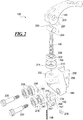
FIG. 1A illustrates a scroll saw 100 according to an exemplary embodiment of the present disclosure. - The
scroll saw 100 includes aworktable 102 mounted on abase 104. Acutting blade 116 extends through an aperture 117 (seeFIG. 1B ) of theworktable 102 and is secured between anupper blade clamp 120 and alower blade clamp 112. As illustrated inFIG. 1A , thecutting blade 116 extends substantially vertically between theupper blade clamp 120 and thelower plate clamp 112. In an exemplary embodiment, thecutting blade 116 and theworktable 102 may be positioned substantially orthogonal to each other, but may be adjusted to other angles by the user as desired. For example, an angle of thecutting blade 116 can be adjusted with respect to theworktable 102 and/or an angle of the worktable can be adjusted with respect to thecutting blade 116. For example, abevel adjustment 122 can be configured to adjust an angle of theworktable 102 with respect to thecutting blade 116 by tilting theworktable 102 as thebevel adjustment 122 moves along the semicircular bracket marked with angle indicia. In another configuration, thebevel adjustment 122 can be configured to adjust an angle of thecutting blade 116 by tilting the upper andlower blade clamps worktable 102 as abevel adjustment 122 moves along the semicircular bracket. - With continued reference to
FIG. 1A , theupper blade clamp 120 is supported by anupper arm 114 and thelower blade clamp 112 is supported by alower arm 110. In operation, theupper arm 114 and thelower arm 110 reciprocate in unison to move thecutting blade 116 along an axis formed between theupper blade clamp 120 and thelower blade clamp 112. For example, as illustrated inFIG. 1A , thecutting blade 116 is in a vertical arrangement and the reciprocation of theupper blade clamp 120 and thelower blade clamp 112 moves thecutting blade 116 in an up and down motion. - The
upper arm 114 supports theupper blade clamp 120 on a first end of theupper arm 114. In an exemplary embodiment, theblade clamp 120 may include ahead 144 that supports aclamp 142 that engages and secures thecutting blade 116. Theblade clamp 120 can include alever 140 that is configured to adjust the position of theclamp 142 based on the position of thelever 140. A second end of theupper arm 114 opposite the first end is connected to anupper support member 106. Theupper support member 106 is further connected to a reciprocation mechanism (not shown) of a type that is known in the art and that is driven by amotor 134. Similarly, thelower support member 110 supports thelower blade clamp 112 on a first end of thelower support member 110. A second end opposite the first end is connected to alower support member 108. Thelower support member 108 is further connected to the reciprocation mechanism that is driven by themotor 134. The reciprocation mechanism may be any mechanism as would be understood by one of ordinary skill that is configured to move thesupport members support members upper arm 114 and thelower arm 110 to move in the reciprocating motion. - The
scroll saw 100 can also include adust blower 118 configured to expel air or other gas near a cutting zone of thecutting blade 116 to blow and remove waste (e.g. sawdust) generated by thecutting blade 116 as thecutting blade 116 cuts a workpiece such as a piece of wood. A vacuum or dust collecting system may be connected to collect dust and debris in certain embodiments. Thescroll saw 100 can be powered by, for example, an electric power source (e.g. an AC or DC power outlet and/or DC battery) and can be connected to the electrical power source by apower cord 124. The power source is not limited to electric power sources and thescroll saw 100 can be powered by other power sources, such as steam or manpower through a crank or other means. Although a powered scroll saw is illustrated, the present blade clamp may be used on a variety of manual and powered saws. - In an exemplary embodiment, the
scroll saw 100 can include one ormore tension adjustments cutting blade 116 by the blade clamps 120 and 112. Thetension adjustments blade clamp 120 and thelower blade clamp 112 to adjust for different blade lengths or to adjust the tension force applied to thecutting blade 116. - With reference to
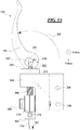
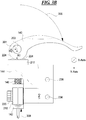
FIG. 1B , thescroll saw 100 can include a foot andarm 126 that can be lowered onto a workpiece to secure the workpiece on theworktable 102 and/or to serve as a location reference or guide. The foot andarm 126 includes an arm to which is attached a U-shaped foot that may have location marks on either side of the blade, as shown. In the enlarged view ofFIG. 1B , theblade clamp 120 is shown, illustrating the components of theblade clamp 120 as mounted on the saw. - The
dust blower 118 includes anozzle 128 that directs a stream of air toward the cutting area. Thenozzle 128 is mounted on a flexible hose and may be directed as desired or may be moved out of the way. - The
cutting blade 116 is held in theclamp 142 by compression exerted on opposite sides of theclamp 142 to roller assemblies orcompression member assemblies 148, depending on the position of thelever 140. -
FIG. 2 illustrates an exploded view of theblade clamp 120 according to an exemplary embodiment of the present disclosure, for example, as may be mounted on thesaw 100 inFIGS. 1A and1B . - In an exemplary embodiment, the
blade clamp 120 may include ahead 144 that supports aclamp 142 which engages and secures thecutting blade 116. Theblade clamp 120 may include alever 140 that is configured to adjust the position of theclamp 142 based on the position of thelever 140. In operation, thelever 140 is moved between an open position and a closed position which corresponds with an open and closed position of theclamp 142. In an exemplary embodiment, theblade clamp 120 may be formed of metal, a metal compound, or a composite, but is not limited thereto. The composition of theblade clamp 120 can be any material or combination of materials as would be understood by one of ordinary skill in the relevant arts. Further, the composition of theblade clamp 120 can be selected to have sufficient tensile strength while allowing for theclamp 142 to be resiliently deformable as discussed below. - Although other embodiments are also possible, in an exemplary embodiment, the
blade clamp 120 can include acam follower 208 disposed on thehead 144. Thecam follower 208 can include asurface 222 that is configured to receive and engage with asurface 224 of thelever 140. Theblade clamp 120 can further include awasher 210 disposed between thecam follower 208 and a top surface of thehead 144. Thewasher 210 includes a cylindrical outer lip into which the cam follower fits and acentral opening 211 through which the threadedconnection member 146 extends. Thewasher 210 may allow thecam follower 208 to rotate about the top surface of thehead 144 when, for example, thelever 140 is rotated. For instance, the distance between theblade clamp 120 and thelever 140 may be adjusted on the threadedconnection member 146 as needed by rotating the threadedconnection member 146 in the block 143 or theconnection member 204 or both. In an exemplary embodiment, thesurface 224 of thelever 140 is aneccentric cam surface 224 that engages thesurface 222 of thecam follower 208. Theeccentric cam surface 224 may be eccentric relative to anaperture 203. Thecam follower 208 can also include anaperture 209 that is configured to receive a connection member (connector) 146 that connects thelever 140 with theclamp 142. In an exemplary embodiment, theconnection member 146 has a cylindrical shape, but is not limited thereto. Theconnection member 146 may be threaded to permit adjustment of the distance between thelever 140 and theclamp 142. - In an exemplary embodiment, the
connection member 146 can be, for example, a bolt, screw, rod, cable, or another fastener as would be understood by those skilled in the arts. Theconnection member 146 can be configured to engage and connect to thelever 140 via aconnection member 204. Theconnection member 204 may be cylindrically shaped, but is not limited thereto, and can include anaperture 205 that receives and connects with theconnection member 146. Theconnection member 146 may be threaded into the aperture or otherwise fastened thereto. Theconnection member 204 can be disposed in anaperture 203 of thelever 140 to connect theconnection member 146 to thelever 140. - In an exemplary embodiment, the
connection member 204 is rotatably disposed within theaperture 203 and theaperture 203 is offset or eccentrically disposed with respect to theeccentric cam surface 224. The eccentric position of theconnection member 204 with respect to thesurface 224 is further illustrated inFIGS. 3A and3B and discussed in detail below. In operation, the eccentricallydisposed connection member 204 causes theconnection member 146 and theclamp 142 to move along the y-axis (FIGS. 3A-3B ) as thelever 140 moves between the open and the closed positions. Theaperture 203 can extend through thelever 140 along an axis ofrotation 301 of thelever 140, and theconnection member 204 can be disposed along the axis of rotation within theaperture 203. For example, as discussed in detail in with reference toFIG. 3A and3B , thelever 140 can be configured to rotate about the axis ofrotation 301 when engaging with thesurface 222 of thecam follower 208. The axis ofrotation 301 may be parallel or substantially parallel to the x-axis extending into and out of the page. - In an exemplary embodiment, the
aperture 205 of theconnection member 204 can be configured to connect to theconnection member 146 via a threaded connection. In this example, theaperture 205 of theconnection member 204 can be a threaded aperture and theconnection member 146 can have threads configured to mate with the threads of theconnection member 204. AlthoughFIG. 2 illustrates theconnection member 146 having threads along its entire length, threads can be included on only a portion of theconnection member 146, such as at the end of theconnection member 146 that connects to theconnection member 204. Further, the connection of theconnection member 146 to theconnection member 204 is not limited to a threaded connection and can include a welded, glued, or other fastening technique as would be understood by one of ordinary skill in the relevant art. Further, the connection of theconnection member 146 with theconnection member 204 can be fixed or allow for theconnection member 146 to rotate with respect to theconnection member 204. - In an exemplary embodiment, the
head 144 includes anaperture 232 that is in registration with theaperture 209 of thecam follower 208. In this example, theconnection member 146 can extend through theaperture 209 of thecam follower 208 through theaperture 232 of thehead 144 to meet with and connect to theclamp 142. In this arrangement, theconnection member 146 extends parallel or substantially parallel to the y-axis, and is configured to move along the y-axis in response to positional changes of thelever 140. In this example, movement of thelever 140 causes theconnection member 146 to move along the y-axis (the vertical direction inFIG. 2 ), thereby causing theclamp 142 to also move along the y-axis. That is, operation of thelever 140 causes theconnection member 146 to move up and down through thehead 144 which causes theclamp 142 to move in an upward or downward direction (directions 304/308 inFIGS 3A-3B ). - In an exemplary embodiment, the
clamp 142 can include anaperture 215 that is configured to receive and connect with theconnection member 146. In this example, a first end of theconnection member 146 engages and connects with theconnection member 204 and the opposite end of theconnection member 146 engages and connects with theaperture 215 of theclamp 142. Theaperture 215 of theclamp 142 can be a threaded aperture and theconnection member 146 can have threads configured to mate with the threads of the threadedaperture 215. Theconnection member 146 and theclamp 142 may be adjusted by threading the connection member further or less for into theaperture 215. Further, the connection of theconnection member 146 to theclamp 142 is not limited to a threaded connection and can include a welded, glued, or other fastening technique as would be understood by one of ordinary skill in the relevant art. The connection of theconnection member 146 with theclamp 142 can be fixed or allow for theconnection member 146 to rotate with respect to theclamp 142. - In an exemplary embodiment, the
lever 140 can be configured to be rotatable (e.g. twistable) abouthead 144. In this example, either thelever 140 is fixed to the end of theconnector 146 connected to thelever 140 or theclamp 142 is fixed to the end of theconnector 146 connected to theclamp 142. In operation, the pivoting rotation of thelever 140 causes theclamp 142 to move up or down along the y-axis. The range of the movement of theclamp 142 relative to the other elements of theblade clamp 102 may be adjusted for reasons which will be explained hereinafter. For example, if theconnector 146 is fixed to theclamp 142, twisting thelever 140 about theconnector 146 causes theconnector 146 to move in theaperture 205 of theconnection member 204 along, for example, the threads of the threaded connection, thereby adjusting the position of theclamp 142 along the y-axis. If theconnector 146 is fixed to thelever 140, twisting thelever 140 causes theconnector 146 to move in theaperture 215 of theclamp 142, thereby adjusting the position of theclamp 142 along the y-axis. - The
clamp 142 can be configured to engage andsecure cutting blades 116 of different thicknesses and sizes. In an exemplary embodiment, theclamp 142 can include aslot 240 that engages an end or near an end of thecutting blade 116. In this example, theslot 240 can be defined by the first and second gripping arms, 241, 242 that extend from ablock 243 of theclamp 142. In an exemplary embodiment, the first and second, grippingarms FIGS. 5A-5B , specifically the arrows 502.1 and 502.2) exerted on the first and the secondgripping arms 241, 242 (seeFIGS. 4A-5B ). In this example, the first and secondgripping arms slot 240 in response to one or more forces (e.g. forces 502) applied to the exterior of theclamp 142, and return to a normal, resting position having awider slot 240 after the force(s) are removed. In operation, when the first and secondgripping arms gripping arms cutting blade 116. - The first and second
gripping arms adjustable grip members 216 that engage thecutting blade 116. For example, theadjustable grip members 216 can include set screws configured to engage threadedbores 217 extending through each of the grippingarms adjustable grip members 216 adjusts the spacing between theadjustable grip members 216 within theslot 240. Theadjustable grip members 216 can be used to increase or decrease the grip spacing for thecutting blade 116 within theslot 240. The inwardly directed ends of theadjustable grip members 216 may provide the grip surface for engaging thesaw blade 116. The grip surface spacing may be adjusted to accommodate thicker orthinner saw blades 116 by adjusting the positions of theadjustable grip members 216 in the threaded bores 217. - One or both of the gripping
arms ramp 244 is the transition between a narrower portion of theclamp 142 at the upper end, relative to the figure, and a wider portion of theclamp 142 at the lower end, relative to the figure, at the free ends of the grippingarms - In an exemplary embodiment, the
blade clamp 120 can include one ormore compression members 218 positioned adjacent to theclamp 142 and secured to thehead 144 via one ormore connectors 220, such as one or more bolts, screws, or other fasteners. Thecompression members 218 can include one or more bearings configured to rotate about arespective connector 220. Thecompression members 218 of the illustrated embodiment are rollers. A pair ofrollers 218 is provided on each side of theclamp 142. In operation, the compression member(s) 218 can be configured to selectively apply pressure/force (e.g. force 502) to theclamp 142, including on one or more of the first and secondgripping arms clamp 142 as the rollers roll over the ramp or step and onto the widergripping arms clamp 142 to move between the compression member(s) 218 while applying the pressing force 502 to the first and secondgripping arms clamp 142 can move between and along thecompression members 218 while thecompression members 218 rotate to facilitate the passing of theclamp 142 between thecompression members 218. - The
head 144 can further include one ormore apertures 234 configured to receive and connect withrespective connectors 220 on which thecompression members 218 are mounted. In an exemplary embodiment, theapertures 234 can be threaded and configured to mate with a threaded portion ofconnectors 220, but are not limited to these fastening means. Thehead 144 can also include theconnection members 230 shown as parallel plates having one ormore apertures 236. The connection member(s) 230 can be configured to engage and connect to theupper arm 114, thereby connecting thehead 144 to theupper arm 114 as illustrated inFIGS. 1A and1B . For example, one or more connectors, such as screws, bolts, or other fastening means can be used to connect theconnection members 230 to theupper arm 114. In an exemplary embodiment, one or more connectors can be inserted throughapertures 236 and secured to theupper arm 114 to facilitate the connection. -
FIGS. 3A-5B illustrates the operation of theblade clamp 120 ofFIG. 2 according to exemplary embodiments of the present disclosure.FIGS. 3A ,4A and 4B illustrate theblade clamp 120 with thelever 140 having been moved from a closed position to an opened position.FIGS. 3B ,5A and 5B illustrate theblade clamp 120 with thelever 140 having been moved from the opened position to the closed position. - With reference to
FIG. 3A , thelever 140 is shown in the open position and has been moved from the closed position to the open position along the direction indicated by anarrow 302. In operation, as thelever 140 moves along theopening direction 302, theeccentric cam surface 224 of thelever 140 may engage thesurface 222 of thecam follower 208, allowing theconnection member 146 to move in adownward direction 304 to open the clamp and release the blade, as will be described in greater detail. Thedirection 304 is parallel or substantially parallel to the y-axis, as indicated in the drawing. - The movement of the
connection member 146 in thedownward direction 304 causes theclamp 142 to also move in thedownward direction 304. Theclamp 142 passes between compression members 218.1 and 218.2 positioned at opposite sides of the clamp 142 (seeFIGS. 4A and 4B ). - In an exemplary embodiment, the
eccentric cam surface 224 is a result of the aperture 203 (and the connection member 204) being eccentrically located within an end portion of thelever 140 such that thecam surface 224 varies in distance from the axis of rotation of thelever 140. For example, thecam surface 224 is shaped so that the distance from the axis of rotation to thecam surface 224 changes gradually from a greater distance R1 to a lesser distance R2. In this example, as thelever 140 is moved between the open and closed positions, theclamp 142 can move a distance along thedirection 304/308 that is approximately equal to the difference between the distances R2 and R1. This is but one example, to which the present apparatus is not limited. - In an exemplary embodiment, one or
more portions outer surface 409 of theclamp 142 can include a ramped and/or curved surface or be otherwise shaped. In this example, theclamp 142 has an increasing width as the distance from theblock 243 of theclamp 142 increases. For example, theclamp 142 has a width W1 near theblock 243 of theclamp 142 and a width W2 at the opposite end of theclamp 142, where the width W2 is greater than the width W1. In an exemplary embodiment, one or both opposite sides of theclamp 142 that contact thecompression members 218 can have a ramped and/or curved surface. In embodiments in which two sides have ramped and/or curved surfaces, the degree of the ramp/curve can be the same or different for the two sides. - In an exemplary embodiment, the
portion 410 of theouter surface 409 is straight and parallel to the y-axis, theportion 412 is ramped or curved such that the width of theclamp 142 increases as the distance from theblock 243 increases, and theportion 414 is straight and parallel to the y-axis. In this arrangement, clamp 142 has a constant width alongportions portion 412. In this example, theportion 412 can correspond to step or ramp 244 shown inFIG. 2 . In certain embodiments, the length of theportion 412 or step or ramp 244 (the distance from theconstant width portion 410 to the constant width portion 414) is less than the difference between the distances R1 and R2. This permits the rotation of thelever 140 to move theclamp 142 between theportions portion 412 orramp 244. - In this embodiment, the
compression members 218 andconnectors 220 cause a first constant force on theclamp 142 when positioned alongportion 414, a decreasing force of theclamp 142 when positioned alongportion 412, and a second constant force on theclamp 142 when positioned alongportion 410, where the first constant force is greater than the second constant force. In certain examples, the force by thecompression members 218 on theclamp 142 atportion 410 may be zero or may be small. In this example, when theclamp 142 is moved over theportion 412 the force on theclamp 142 increases or decreases depending on the direction of travel of theclamp 142. The movement of thelever 140 from the closed position to the open position (movement alongdirection 302 shown inFIG. 3A ) causes a constant clamping force and a decreasing tension force on theblade 116 when thecompression members 218 move alongportion 414, and causes a decreasing clamping force and a decreasing tension force on theblade 116 when thecompression members 218 move alongportion 412. When thelever 140 is moved further to bring theportion 410 between thecompression members 218, the clamping force on theblade 116 is released. With the clamping force released, theblade 116 may be removed or repositioned. - In this embodiment, the
adjustable grip members 216 have been adjusted to securely hold theblade 116 within theclamp 142 in the closed position (i.e., theblade 116 is held in position within the clamp 142), and the movement of thelever 140 from the closed position to the open position causes a decreasing tension force on theblade 116 and release of theblade 116 when thecompression members 218 move to theportion 410. - In other embodiments, the
clamp 142 may include more or fewer shaped portions of theouter surface 409, and the straight and ramped/curved configurations of theses portions can be any combination as would be understood by one of ordinary skill in the relevant arts. For example, theouter surface 409 may include two portions: a straight portion followed by a ramped/curved portion, or a ramped/curved portion followed by a straight portion; a single curved/ramped portion; multiple portions in any arrangement or another configuration as would be understood by one of ordinary skill in the relevant arts. - In an exemplary embodiment, the
first member 241 and/or thesecond member 242 can have increasing widths as the first and/or secondgripping members block 243. For example, a sidewall 408.1 of thefirst member 241 and/or a sidewall 408.2 of thesecond member 242 can have a width D1 near theblock 243 and a width D2 at the opposite end of themember 241 and/ormember 242, where width D2 is greater than width D1. - As the
clamp 142 moves between thecompression members 218 in thedirection 304, the force exerted on theclamp 142 by thecompression members 218 decreases, thereby decreasing a clamping force exerted by theclamp 142 on thecutting blade 116 as the first and secondgripping members FIG. 4A and 4B ). In this example, the first and secondgripping members clamp 142 separate as the force exerted on theclamp 142 by thecompression members 218 decreases due to the smaller width W1 of theclamp 142 positioned between thecompression members 218. Further, theslot 240 expands as the first and secondgripping members cutting blade 116 decreases as theclamp 142 moves in the downward direction 304 (along the y-axis) towards thelower clamp 112. - The movement of the
lever 140 in thedirection 302 both releases the tension on the blade and releases the grip on the blade. A user may release the blade tension and blade grip with one hand, for example, while the other hand holds the now released blade. - With reference to
FIG. 3B , thelever 140 has been moved from the open position along the direction of thearrow 306 to the illustrated closed position (see alsoFIGS. 5A and 5B ). In operation, as thelever 140 moves along thedirection 306, theeccentric cam surface 224 of thelever 140 engages thesurface 222 of thecam follower 208 so that the axis of rotation of the lever is moved upward, causing theconnection member 146 to move in anupward direction 308. Thedirection 308 is parallel or substantially parallel to the y-axis. - As discussed above, the
eccentric cam surface 224 can be created by the aperture 203 (and the connection member 204) being eccentrically located within the end of thelever 140 such that the distance R1 is greater than the distance R2 in an exemplary embodiment. In this example, theclamp 142 can move a distance along thedirection 304/308 that is approximately the difference between the distances R2 and R1 as the lever is moved between the open position (FIG. 3A ) and closed position (FIG. 3B ). - The movement of the
connection member 146 in theupward direction 308 causes theclamp 142 to also move in theupward direction 308. Theclamp 142 moves between compression members 218.1 and 218.2 positioned at opposite sides of the clamp 142 (seeFIGS. 5A and 5B ). In exemplary embodiments where one ormore portions outer surface 409 of theclamp 142 have a ramped and/or curved surface, theclamp 142 has an increasing width as the distance from theblock 243 of theclamp 142 increases. For example, theclamp 142 has a width W1 near theblock 243 of theclamp 142 and a width W2 at the opposite end of theclamp 142, where the width W2 is greater than the width W1. - As the
clamp 142 passes throughcompression members 218 in thedirection 308, due to the increasing width of the of theclamp 142, the force 502 exerted on theclamp 142 by thecompression members 218 increases, thereby initiating or increasing a clamping force exerted by theclamp 142 on thecutting blade 116 as the first and secondgripping members cutting blade 116 to a clamped position (position illustrated inFIG. 5A and 5B ). In this example, the first and secondgripping members clamp 142 bend inward as the force 502 exerted on theclamp 142 by thecompression members 218 increases due to the larger width W2 of theclamp 142 positioned between thecompression members 218. In this example, theslot 240 contracts as the first and secondgripping members - As the clamping or gripping force on the blade is increased, the tension on the
cutting blade 116 also increases as theclamp 142 moves in the upward direction 308 (along the x-axis) away from thelower clamp 112. The grippingmembers 216 have been adjusted, for example by the user, to grip theblade 116 as thecompression members 218 roll over theramp 412. Once theblade 116 is gripped, further movement of thelever 140 applies tension to the blade and then increases the tension on the blade as thecompression members 218 move along thelinear portion 414. - In this embodiment, the
compression members 218 cause the second constant force on theclamp 142 when positioned alongportion 410, an increasing force on theclamp 142 when positioned alongportion 412, and the first constant force on theclamp 142 when positioned alongportion 414, where the first constant force is greater than the second constant force. In this example, the force when theclamp 142 is positioned alongportion 412 increases from the second constant force to the first constant force as theclamp 142 moves in thedirection 308. Movement of thelever 140 from the open position to the closed position (movement along thedirection 306 shown inFIG. 3B ) initiates and then increases a clamping force on the blade and initiates and then increases a tension force on theblade 116 when thecompression members 218 move alongportion 412. Further movement of thelever 140 results in application of a constant clamping force and an increasing tension force on theblade 116 as thecompression members 218 move alongportion 414. In this embodiment, if theadjustment members 216 are adjusted to securely hold theblade 116 within the clamp 142 (i.e., theblade 116 is held in position within the clamp 142), the movement of thelever 140 from the open position to the closed position causes an increasing tension force on theblade 116 when thecompression members 218 move alongportion 410. - A user may hold the blade in one hand to position the blade in the clamp and may move the
lever 140 from the open position to the closed position to both grip the blade in the blade clamp and apply the desired tension to the blade with one movement by one hand. The user may easily remove and replace the blade with a simple, one lever adjustment. The user may change blades or reposition the blade as desired. As a result of an easily released and easily mounted blade, a scroll saw having the present blade mount may be used to cut workpieces having one or more interior cuts that are not accessible by an entrance slot from the edge of the workpiece. In one example, a user may release the blade, pass one end of the blade through a starter hole in the workpiece and then remount the blade in the saw using the single lever mounting. With the blade extending through the workpiece, the saw may be operated to cut a shape that is within the workpiece without the cut extending to the edge of the workpiece. The user may then release the blade and remove the blade the workpiece or may move the blade to another starter hole for another interior cut. Multiple such interior cuts may be made in a workpiece by mounting and releasing the blade for each interior cut. Such a task would be tedious and time consuming with a saw requiring separate mounting and tensioning of the blade, particularly if the mounting and tensioning requires tools such as wrenches and screwdrivers to operate fasteners or other devices that either hold the blade or tension the blade. The single-handed, tool-less, combined gripping and tensioning operation of the present blade clamp simplifies the process. Intricate workpiece designs are possible with less effort and time by the user. - In an exemplary embodiment, with reference to
FIGS. 2 and4B , theclamp 142 includes theblock 243 and first and secondgripping members gripping member 241 includes a sidewall portion 408.1 connected to a clamping portion 412.1. Similarly, the second grippingmember 242 includes sidewall portion 408.2 connected to a clamping portion 412.2. In this example, theblock 243, sidewall portions 408, and clampingportions 412 define anaperture 402 that extends through theclamp 142. - In an exemplary embodiment, one or more of the clamping
portions 412 includes alip 406 that is extends across theslot 240 and is configured to prevent thecutting blade 116 from extending into theaperture 402, for example, when mounting thecutting blade 116 in theslot 240. In an exemplary embodiment, theclamp 142 is substantially C-shaped or U-shaped. - In exemplary embodiments, the
lever 140 can be replaced by another adjustment device configured to raise or lower theconnection member 146 along the y-axis. For example, thelever 140 can be replaced with, for example, a handle fixed to theconnection member 146, a nut, a wingnut, a handle threaded onto theconnection member 146, or another adjustment device as would be understood by one of ordinary skill in the relevant arts. - In these examples, either the adjustment device is fixed to the end of the
connector 146 connected to the adjustment device or theclamp 142 is fixed to the end of theconnector 146 connected to theclamp 142, or both. In operation, the rotation of the adjustment device causes theclamp 142 to move up or down along the y-axis. For example, if theconnector 146 is fixed to theclamp 142, the rotation of the adjustment device causes theconnector 146 to further enter an aperture of the adjustment device, thereby adjusting the position of theclamp 142 along the y-axis. If theconnector 146 is fixed to the adjustment device, the rotation of the adjustment device causes theconnector 146 to further enter theaperture 215 of theclamp 142, thereby adjusting the position of theclamp 142 along the y-axis. - An exemplary method of the
scroll saw 100 will be described below with reference toFIGS. 1A to 5B . In an exemplary embodiment, to mount thecutting blade 116 on thescroll saw 100, the lower end of thecutting blade 116 is inserted throughaperture 117 and engages and is secured to thelower clamp 112. The upper end of thecutting blade 116 is then placed in theslot 240. Thelever 140 is then moved from the open position to the closed position in thedirection 306, which causesclamp 142 to move from the open to the closed position of theclamp 142. As theclamp 142 moves to the closed position, the clampingportions 412 provide a clamping force on the blade 116 (e.g. forces 502 inFIGS. 5A-5B ) and/or theclamp 142 provides a tension force on theblade 116 as the clamp moves in thedirection 308. To remove thecutting blade 116, the reverse operations can be performed. - The aforementioned description of the specific embodiments will so fully reveal the general nature of the disclosure that others can, by applying knowledge within the skill of the art, readily modify and/or adapt for various applications such specific embodiments, without undue experimentation, and without departing from the general concept of the present disclosure. Therefore, such adaptations and modifications are intended to be within the meaning and range of equivalents of the disclosed embodiments, based on the teaching and guidance presented herein. It is to be understood that the phraseology or terminology herein is for the purpose of description and not of limitation, such that the terminology or phraseology of the present specification is to be interpreted by the skilled artisan in light of the teachings and guidance.
- References in the specification to "one embodiment," "an embodiment," "an exemplary embodiment," etc., indicate that the embodiment described may include a particular feature, structure, or characteristic, but every embodiment may not necessarily include the particular feature, structure, or characteristic. Moreover, such phrases are not necessarily referring to the same embodiment. Further, when a particular feature, structure, or characteristic is described in connection with an embodiment, it is submitted that it is within the knowledge of one skilled in the art to affect such feature, structure, or characteristic in connection with other embodiments whether or not explicitly described.
- The exemplary embodiments described herein are provided for illustrative purposes, and are not limiting. Other exemplary embodiments are possible, and modifications may be made to the exemplary embodiments. Therefore, the specification is not meant to limit the disclosure. Rather, the scope of the disclosure is defined only in accordance with the following claims.
Claims (13)
- A blade clamp (120) of a saw (100) operable to secure a cutting blade (116) in the saw (100), the blade clamp (120) comprising:a clamp (142) having first and second gripping members (216) configured to hold the cutting blade (116) between the first and the second gripping members (216);a connection member (146) having a first end connected to the clamp (142) and having a second end;a lever (140) connected to the second end of the connection member (146), the lever (140) being operable to move between first and second lever positions; anda head (144) that receives the connection member (146) that extends through an aperture (234) of the head (144), the connection member (146) being configured to move along a first axis through the aperture (234) of the head (144) and move the clamp (142) along the first axis as the lever (140) is moved from the first lever position to the second lever position,wherein the first and the second gripping members (216) of the clamp (142) are configured to apply tension to the cutting blade (116) as the lever (140) is moved from the first lever position to the second lever position,
characterised in that the first and the second gripping members (216) of the clamp (142) are further configured to clamp the cutting blade (116) along a second axis orthogonal to the first axis as the lever (140) is moved from the first lever position to the second lever position. - A scroll saw (100) having a cutting blade (116), the scroll saw (100) comprising:a base (104) supporting a worktable (102) and a motor (134) that is configured to move the cutting blade (116) along a first axis;and a blade clamp (120) in accordance with claim 1.
- A scroll saw (100) having a cutting blade (116), the scroll saw (100) comprising:a base (104) supporting a worktable (102) and a motor (134) that is configured to move the cutting blade (116) along a first axis;a blade clamp (120) including:a clamp (142) having first and second gripping members (216) configured to hold a first end of the cutting blade (116) between the first and the second gripping members (216);a connection member (146) connected to the clamp (142);a lever (140) connected to the clamp (142) by the connection member (146), the lever (140) being configured to move between first and second lever positions; anda head (144) that receives the connection member (146) that extends through an aperture (234) of the head (144), the connection member (146) being configured to move along the first axis through the aperture (234) of the head (144) and move the clamp (142) along the first axis as the lever (140) is moved from the first lever position to the second lever position,wherein the first and the second gripping members (216) of the clamp (142) are configured to apply tension to the cutting blade (116) along the first axis as the lever (140) is moved from the first lever position to the second lever position; anda lower clamp (112) configured to hold a second end of the cutting blade (116) opposite the first end,characterised in that the first and the second gripping members (216) of the clamp (142) are further configured to clamp the cutting blade (116) along a second axis orthogonal to the first axis as the lever (170) is moved from the first lever position to the second lever position.
- The blade clamp of claim 1, or the scroll saw of claim 2 or claim 3, wherein the lever (140) comprises an eccentric cam surface (224) that is configured to engage a cam follower (208), the connection member (146) being configured to move along the first axis through the aperture (234) of the head (144) and move the clamp (142) along the first axis based on a position of the eccentric cam surface (224) with respect to the cam follower (208).
- The blade clamp or scroll saw of claim 4, wherein the cam follower (208) is disposed on the head (144) and the connection member (146) extends through an aperture (209) of the cam follower (208) to connect to the lever (140).
- The blade clamp of claim 1, or of any preceding claim, or the scroll saw of claim 2 or claim 3 or of any preceding claim, wherein the clamp (142) is configured to apply an increasing clamping force on the cutting blade (116) and an increasing tension force on the cutting blade (116) as the clamp (142) moves along the first axis in response to the lever (140) being moved from the first lever position to the second lever position.
- The blade clamp or scroll saw of claim 6, wherein the clamping force is along the second axis and the tension force is along the first axis.
- The blade clamp of claim 1, or of any preceding claim, or the scroll saw of claim 2 or claim 3 or of any preceding claim, wherein the head (144) comprises first and second compression members (218) that are configured to apply respective forces on the first and second gripping members (216) of the clamp (142) as the clamp moves along the first axis to cause the first and the second gripping members (216) of the clamp (142) to clamp the cutting blade (116).
- The blade clamp of claim 8, wherein the first and second gripping members (216) of the clamp (142) have respective ramped surfaces that engage the first and the second compression members (218), the respective ramped surfaces causing the respective forces on the first and the second gripping members (216) to increase as the clamp (142) moves along the first axis in response to the lever (140) being moved from the first lever position to the second lever position; or
the scroll saw of claim 8 wherein the first and second gripping members (216) of the clamp (142) have respective ramped surfaces that engage the first and the second compression members (218). - The blade clamp of claim 1 or of any preceding claim, wherein the cutting blade (116) extends along the first axis.
- The scroll saw of claim 7, wherein the clamp (142) and the lower clamp (112) separate as the clamp (142) moves along the first axis.
- The scroll saw of claim 2 or claim 3, or of any preceding claim, wherein the cutting blade (116) extends along the first axis between the clamp (142) and the lower clamp (112).
- A blade clamp (120) of a saw (100) operable to secure a cutting blade (116) in the saw, the blade clamp (120) comprising:a clamp (142) having first and second gripping members (216) configured to hold the cutting blade (116) between the first and the second gripping members (216), and wherein the first and second gripping members (216) are further configured to apply tension to the cutting blade (116) based on the movement of the clamp (142) along a first axis;a lever (170) including an eccentric cam surface (224), the lever (140) being connected to the clamp (142) by a connection member (146) and configured to move between first and second lever positions; anda head (144) receiving the connection member (146) that extends through an aperture (234) of the head (144),characterised in that the head (144) comprises a cam follower (208) that is configured to engage the eccentric cam surface (224) of the lever (170), wherein the connection member (146) is configured to move along the first axis through the aperture (234) of the head (144) and move the clamp (142) along the first axis based on the engagement of the eccentric cam surface (224) with the cam follower (208) as the lever (170) is moved from the first lever position to the second lever position; and
first and second compression members (218) disposed on the head (144) that are configured to apply respective forces on the first and second gripping members (216) of the clamp (142) as the clamp moves along the first axis to cause the first and the second gripping members (216) of the clamp (142) to clamp the cutting blade (116), the first and second gripping members (216) of the clamp (142) having respective ramped surfaces that engage the first and the second compression members (218),
wherein the respective ramped surfaces cause the respective forces on the first and the second gripping members (216) to increase as the clamp (142) moves along the first axis in response to the lever (170) being moved from the first lever position to the second lever position, and, as the lever (170) is moved from the first lever position to the second lever position, the first and the second gripping members (216) of the clamp (142) are configured to clamp the cutting blade (116) along a second axis orthogonal to the first axis based on the increasing respective forces on the first and the second gripping members (216).
Applications Claiming Priority (2)
| Application Number | Priority Date | Filing Date | Title |
|---|---|---|---|
| US201662325165P | 2016-04-20 | 2016-04-20 | |
| US15/472,472 US10369641B2 (en) | 2016-04-20 | 2017-03-29 | Combined blade clamp and tensioner for scroll saw |
Publications (2)
| Publication Number | Publication Date |
|---|---|
| EP3235583A1 EP3235583A1 (en) | 2017-10-25 |
| EP3235583B1 true EP3235583B1 (en) | 2019-01-23 |
Family
ID=58544781
Family Applications (1)
| Application Number | Title | Priority Date | Filing Date |
|---|---|---|---|
| EP17165726.5A Active EP3235583B1 (en) | 2016-04-20 | 2017-04-10 | Combined blade clamp and tensioner for scroll saw |
Country Status (8)
| Country | Link |
|---|---|
| US (1) | US10369641B2 (en) |
| EP (1) | EP3235583B1 (en) |
| KR (1) | KR20170120039A (en) |
| CN (1) | CN107303613A (en) |
| AU (1) | AU2017202310B2 (en) |
| CA (1) | CA2964733A1 (en) |
| MX (1) | MX2017004999A (en) |
| RU (1) | RU2017113442A (en) |
Families Citing this family (3)
| Publication number | Priority date | Publication date | Assignee | Title |
|---|---|---|---|---|
| US10843363B2 (en) * | 2017-11-10 | 2020-11-24 | Urschel Laboratories, Inc. | Knife assemblies and cutting apparatuses comprising the same |
| CN110405276B (en) * | 2019-08-07 | 2024-02-09 | 宁波汉浦工具有限公司 | Dual-purpose saw sword |
| CN112775492A (en) * | 2021-01-31 | 2021-05-11 | 刘沛蕾 | Aluminum alloy door and window's processing agency |
Family Cites Families (9)
| Publication number | Priority date | Publication date | Assignee | Title |
|---|---|---|---|---|
| US5016512A (en) * | 1990-01-02 | 1991-05-21 | Huang Chun Chi | Scroll saw blade holding system |
| US5327807A (en) * | 1993-08-20 | 1994-07-12 | P & F Brother Industrial Corporation | Scroll saw with saw blade fastening and tension adjusting device |
| EP0714730A3 (en) * | 1994-12-02 | 1997-04-23 | Makita Corp | Blade mounting device in cutting tool |
| FR2770163B3 (en) | 1997-10-23 | 1999-12-10 | Andre Dieu | FAST RELEASE AND FASTENING MECHANISM OF A LINEAR TOOL END |
| US5941153A (en) | 1997-11-10 | 1999-08-24 | P & F Brothers Industrial Corporation | Quick release saw blade chuck for a scroll saw |
| US6530579B1 (en) * | 2000-07-11 | 2003-03-11 | Jan P. Houben | Wedging blade clamp for scroll saw |
| TWM300608U (en) * | 2006-05-17 | 2006-11-11 | Rexon Ind Corp Ltd | Blade-clamping mechanism of coping saw machine |
| US20110247224A1 (en) * | 2010-04-09 | 2011-10-13 | Alltrade Tools Llc | Cable saw system |
| TWM495286U (en) * | 2014-08-13 | 2015-02-11 | Qiong-Yu Zhang | Improvement of transmission structure for scroll saw machine |
-
2017
- 2017-03-29 US US15/472,472 patent/US10369641B2/en active Active
- 2017-04-07 AU AU2017202310A patent/AU2017202310B2/en active Active
- 2017-04-10 EP EP17165726.5A patent/EP3235583B1/en active Active
- 2017-04-17 MX MX2017004999A patent/MX2017004999A/en unknown
- 2017-04-19 KR KR1020170050449A patent/KR20170120039A/en unknown
- 2017-04-19 CA CA2964733A patent/CA2964733A1/en active Pending
- 2017-04-19 RU RU2017113442A patent/RU2017113442A/en not_active Application Discontinuation
- 2017-04-20 CN CN201710259789.6A patent/CN107303613A/en active Pending
Non-Patent Citations (1)
| Title |
|---|
| None * |
Also Published As
| Publication number | Publication date |
|---|---|
| KR20170120039A (en) | 2017-10-30 |
| US10369641B2 (en) | 2019-08-06 |
| US20170304915A1 (en) | 2017-10-26 |
| AU2017202310A1 (en) | 2017-11-09 |
| RU2017113442A (en) | 2018-10-19 |
| EP3235583A1 (en) | 2017-10-25 |
| AU2017202310B2 (en) | 2022-09-29 |
| CA2964733A1 (en) | 2017-10-20 |
| CN107303613A (en) | 2017-10-31 |
| MX2017004999A (en) | 2018-08-16 |
Similar Documents
| Publication | Publication Date | Title |
|---|---|---|
| EP3235583B1 (en) | Combined blade clamp and tensioner for scroll saw | |
| US5483858A (en) | Sawing machine having angle-adjustable clamping mechanism and safety alignment mechanism | |
| US5301726A (en) | Workpiece stabilizer for bench tools | |
| US8359961B2 (en) | Portable variable-angle cutting guide | |
| US20060201297A1 (en) | Powered feed system for use with a machine saw table for providing guided motion along at least one axis | |
| EA022532B1 (en) | Power tool cutting apparatus | |
| US7757592B2 (en) | Power saw miter guide | |
| EP1987916A1 (en) | A grinding machine and a grinding jig therefore | |
| CN111511506B (en) | Support attachment mechanism for a workpiece support mechanism | |
| US10518434B2 (en) | Structure of power carpentry feeder machine | |
| CN111151606B (en) | Panel beating bender convenient to location | |
| US6990882B2 (en) | Device for precision cuts on aluminum and vinyl siding and other construction materials | |
| CA2241166C (en) | Self-adjusting clamping device | |
| US5775192A (en) | Sliding miter cutter | |
| US6868612B2 (en) | Cutting guide device for circular saws | |
| US20050172507A1 (en) | Device for processing a workpiece | |
| CA2736715C (en) | Docking and miter saw having an inset preferably delimiting a saw slot | |
| US9387572B2 (en) | Workpiece clamp for miter saw | |
| EP1000716A2 (en) | Workbench specially adapted for use as a saw horse | |
| JP2012086503A (en) | Saw auxiliary tool | |
| CN220216332U (en) | Bending device capable of adjusting bending angle | |
| US4524663A (en) | Power hacksaw | |
| CN220498230U (en) | Welding operation auxiliary device with adjustable | |
| CN219684580U (en) | Sliding guide rail mechanism for adjusting distance between guide plates | |
| US20160136743A1 (en) | Auxiliary device for cutting in bandsaw |
Legal Events
| Date | Code | Title | Description |
|---|---|---|---|
| PUAI | Public reference made under article 153(3) epc to a published international application that has entered the european phase |
Free format text: ORIGINAL CODE: 0009012 |
|
| STAA | Information on the status of an ep patent application or granted ep patent |
Free format text: STATUS: THE APPLICATION HAS BEEN PUBLISHED |
|
| AK | Designated contracting states |
Kind code of ref document: A1 Designated state(s): AL AT BE BG CH CY CZ DE DK EE ES FI FR GB GR HR HU IE IS IT LI LT LU LV MC MK MT NL NO PL PT RO RS SE SI SK SM TR |
|
| AX | Request for extension of the european patent |
Extension state: BA ME |
|
| STAA | Information on the status of an ep patent application or granted ep patent |
Free format text: STATUS: REQUEST FOR EXAMINATION WAS MADE |
|
| 17P | Request for examination filed |
Effective date: 20180410 |
|
| RBV | Designated contracting states (corrected) |
Designated state(s): AL AT BE BG CH CY CZ DE DK EE ES FI FR GB GR HR HU IE IS IT LI LT LU LV MC MK MT NL NO PL PT RO RS SE SI SK SM TR |
|
| GRAP | Despatch of communication of intention to grant a patent |
Free format text: ORIGINAL CODE: EPIDOSNIGR1 |
|
| STAA | Information on the status of an ep patent application or granted ep patent |
Free format text: STATUS: GRANT OF PATENT IS INTENDED |
|
| INTG | Intention to grant announced |
Effective date: 20180905 |
|
| GRAS | Grant fee paid |
Free format text: ORIGINAL CODE: EPIDOSNIGR3 |
|
| GRAA | (expected) grant |
Free format text: ORIGINAL CODE: 0009210 |
|
| STAA | Information on the status of an ep patent application or granted ep patent |
Free format text: STATUS: THE PATENT HAS BEEN GRANTED |
|
| AK | Designated contracting states |
Kind code of ref document: B1 Designated state(s): AL AT BE BG CH CY CZ DE DK EE ES FI FR GB GR HR HU IE IS IT LI LT LU LV MC MK MT NL NO PL PT RO RS SE SI SK SM TR |
|
| REG | Reference to a national code |
Ref country code: GB Ref legal event code: FG4D |
|
| REG | Reference to a national code |
Ref country code: CH Ref legal event code: EP |
|
| REG | Reference to a national code |
Ref country code: AT Ref legal event code: REF Ref document number: 1091058 Country of ref document: AT Kind code of ref document: T Effective date: 20190215 |
|
| REG | Reference to a national code |
Ref country code: IE Ref legal event code: FG4D |
|
| REG | Reference to a national code |
Ref country code: DE Ref legal event code: R096 Ref document number: 602017001858 Country of ref document: DE |
|
| REG | Reference to a national code |
Ref country code: CH Ref legal event code: NV Representative=s name: VALIPAT S.A. C/O BOVARD SA NEUCHATEL, CH |
|
| REG | Reference to a national code |
Ref country code: NL Ref legal event code: MP Effective date: 20190123 |
|
| PG25 | Lapsed in a contracting state [announced via postgrant information from national office to epo] |
Ref country code: NL Free format text: LAPSE BECAUSE OF FAILURE TO SUBMIT A TRANSLATION OF THE DESCRIPTION OR TO PAY THE FEE WITHIN THE PRESCRIBED TIME-LIMIT Effective date: 20190123 |
|
| PG25 | Lapsed in a contracting state [announced via postgrant information from national office to epo] |
Ref country code: FI Free format text: LAPSE BECAUSE OF FAILURE TO SUBMIT A TRANSLATION OF THE DESCRIPTION OR TO PAY THE FEE WITHIN THE PRESCRIBED TIME-LIMIT Effective date: 20190123 Ref country code: LT Free format text: LAPSE BECAUSE OF FAILURE TO SUBMIT A TRANSLATION OF THE DESCRIPTION OR TO PAY THE FEE WITHIN THE PRESCRIBED TIME-LIMIT Effective date: 20190123 Ref country code: PL Free format text: LAPSE BECAUSE OF FAILURE TO SUBMIT A TRANSLATION OF THE DESCRIPTION OR TO PAY THE FEE WITHIN THE PRESCRIBED TIME-LIMIT Effective date: 20190123 Ref country code: SE Free format text: LAPSE BECAUSE OF FAILURE TO SUBMIT A TRANSLATION OF THE DESCRIPTION OR TO PAY THE FEE WITHIN THE PRESCRIBED TIME-LIMIT Effective date: 20190123 Ref country code: NO Free format text: LAPSE BECAUSE OF FAILURE TO SUBMIT A TRANSLATION OF THE DESCRIPTION OR TO PAY THE FEE WITHIN THE PRESCRIBED TIME-LIMIT Effective date: 20190423 Ref country code: PT Free format text: LAPSE BECAUSE OF FAILURE TO SUBMIT A TRANSLATION OF THE DESCRIPTION OR TO PAY THE FEE WITHIN THE PRESCRIBED TIME-LIMIT Effective date: 20190523 Ref country code: ES Free format text: LAPSE BECAUSE OF FAILURE TO SUBMIT A TRANSLATION OF THE DESCRIPTION OR TO PAY THE FEE WITHIN THE PRESCRIBED TIME-LIMIT Effective date: 20190123 |
|
| PGFP | Annual fee paid to national office [announced via postgrant information from national office to epo] |
Ref country code: DE Payment date: 20190429 Year of fee payment: 3 |
|
| REG | Reference to a national code |
Ref country code: AT Ref legal event code: MK05 Ref document number: 1091058 Country of ref document: AT Kind code of ref document: T Effective date: 20190123 |
|
| PG25 | Lapsed in a contracting state [announced via postgrant information from national office to epo] |
Ref country code: BG Free format text: LAPSE BECAUSE OF FAILURE TO SUBMIT A TRANSLATION OF THE DESCRIPTION OR TO PAY THE FEE WITHIN THE PRESCRIBED TIME-LIMIT Effective date: 20190423 Ref country code: GR Free format text: LAPSE BECAUSE OF FAILURE TO SUBMIT A TRANSLATION OF THE DESCRIPTION OR TO PAY THE FEE WITHIN THE PRESCRIBED TIME-LIMIT Effective date: 20190424 Ref country code: HR Free format text: LAPSE BECAUSE OF FAILURE TO SUBMIT A TRANSLATION OF THE DESCRIPTION OR TO PAY THE FEE WITHIN THE PRESCRIBED TIME-LIMIT Effective date: 20190123 Ref country code: RS Free format text: LAPSE BECAUSE OF FAILURE TO SUBMIT A TRANSLATION OF THE DESCRIPTION OR TO PAY THE FEE WITHIN THE PRESCRIBED TIME-LIMIT Effective date: 20190123 Ref country code: LV Free format text: LAPSE BECAUSE OF FAILURE TO SUBMIT A TRANSLATION OF THE DESCRIPTION OR TO PAY THE FEE WITHIN THE PRESCRIBED TIME-LIMIT Effective date: 20190123 Ref country code: IS Free format text: LAPSE BECAUSE OF FAILURE TO SUBMIT A TRANSLATION OF THE DESCRIPTION OR TO PAY THE FEE WITHIN THE PRESCRIBED TIME-LIMIT Effective date: 20190523 |
|
| REG | Reference to a national code |
Ref country code: DE Ref legal event code: R097 Ref document number: 602017001858 Country of ref document: DE |
|
| PG25 | Lapsed in a contracting state [announced via postgrant information from national office to epo] |
Ref country code: AL Free format text: LAPSE BECAUSE OF FAILURE TO SUBMIT A TRANSLATION OF THE DESCRIPTION OR TO PAY THE FEE WITHIN THE PRESCRIBED TIME-LIMIT Effective date: 20190123 Ref country code: EE Free format text: LAPSE BECAUSE OF FAILURE TO SUBMIT A TRANSLATION OF THE DESCRIPTION OR TO PAY THE FEE WITHIN THE PRESCRIBED TIME-LIMIT Effective date: 20190123 Ref country code: DK Free format text: LAPSE BECAUSE OF FAILURE TO SUBMIT A TRANSLATION OF THE DESCRIPTION OR TO PAY THE FEE WITHIN THE PRESCRIBED TIME-LIMIT Effective date: 20190123 Ref country code: IT Free format text: LAPSE BECAUSE OF FAILURE TO SUBMIT A TRANSLATION OF THE DESCRIPTION OR TO PAY THE FEE WITHIN THE PRESCRIBED TIME-LIMIT Effective date: 20190123 Ref country code: RO Free format text: LAPSE BECAUSE OF FAILURE TO SUBMIT A TRANSLATION OF THE DESCRIPTION OR TO PAY THE FEE WITHIN THE PRESCRIBED TIME-LIMIT Effective date: 20190123 Ref country code: CZ Free format text: LAPSE BECAUSE OF FAILURE TO SUBMIT A TRANSLATION OF THE DESCRIPTION OR TO PAY THE FEE WITHIN THE PRESCRIBED TIME-LIMIT Effective date: 20190123 Ref country code: SK Free format text: LAPSE BECAUSE OF FAILURE TO SUBMIT A TRANSLATION OF THE DESCRIPTION OR TO PAY THE FEE WITHIN THE PRESCRIBED TIME-LIMIT Effective date: 20190123 |
|
| PG25 | Lapsed in a contracting state [announced via postgrant information from national office to epo] |
Ref country code: SM Free format text: LAPSE BECAUSE OF FAILURE TO SUBMIT A TRANSLATION OF THE DESCRIPTION OR TO PAY THE FEE WITHIN THE PRESCRIBED TIME-LIMIT Effective date: 20190123 |
|
| PLBE | No opposition filed within time limit |
Free format text: ORIGINAL CODE: 0009261 |
|
| STAA | Information on the status of an ep patent application or granted ep patent |
Free format text: STATUS: NO OPPOSITION FILED WITHIN TIME LIMIT |
|
| PG25 | Lapsed in a contracting state [announced via postgrant information from national office to epo] |
Ref country code: LU Free format text: LAPSE BECAUSE OF NON-PAYMENT OF DUE FEES Effective date: 20190410 Ref country code: MC Free format text: LAPSE BECAUSE OF FAILURE TO SUBMIT A TRANSLATION OF THE DESCRIPTION OR TO PAY THE FEE WITHIN THE PRESCRIBED TIME-LIMIT Effective date: 20190123 Ref country code: AT Free format text: LAPSE BECAUSE OF FAILURE TO SUBMIT A TRANSLATION OF THE DESCRIPTION OR TO PAY THE FEE WITHIN THE PRESCRIBED TIME-LIMIT Effective date: 20190123 |
|
| 26N | No opposition filed |
Effective date: 20191024 |
|
| PG25 | Lapsed in a contracting state [announced via postgrant information from national office to epo] |
Ref country code: SI Free format text: LAPSE BECAUSE OF FAILURE TO SUBMIT A TRANSLATION OF THE DESCRIPTION OR TO PAY THE FEE WITHIN THE PRESCRIBED TIME-LIMIT Effective date: 20190123 |
|
| PGFP | Annual fee paid to national office [announced via postgrant information from national office to epo] |
Ref country code: BE Payment date: 20191011 Year of fee payment: 3 |
|
| PG25 | Lapsed in a contracting state [announced via postgrant information from national office to epo] |
Ref country code: TR Free format text: LAPSE BECAUSE OF FAILURE TO SUBMIT A TRANSLATION OF THE DESCRIPTION OR TO PAY THE FEE WITHIN THE PRESCRIBED TIME-LIMIT Effective date: 20190123 |
|
| PG25 | Lapsed in a contracting state [announced via postgrant information from national office to epo] |
Ref country code: IE Free format text: LAPSE BECAUSE OF NON-PAYMENT OF DUE FEES Effective date: 20190410 |
|
| REG | Reference to a national code |
Ref country code: DE Ref legal event code: R119 Ref document number: 602017001858 Country of ref document: DE |
|
| REG | Reference to a national code |
Ref country code: CH Ref legal event code: PL |
|
| PG25 | Lapsed in a contracting state [announced via postgrant information from national office to epo] |
Ref country code: CH Free format text: LAPSE BECAUSE OF NON-PAYMENT OF DUE FEES Effective date: 20200430 Ref country code: LI Free format text: LAPSE BECAUSE OF NON-PAYMENT OF DUE FEES Effective date: 20200430 Ref country code: DE Free format text: LAPSE BECAUSE OF NON-PAYMENT OF DUE FEES Effective date: 20201103 |
|
| REG | Reference to a national code |
Ref country code: BE Ref legal event code: MM Effective date: 20200430 |
|
| PG25 | Lapsed in a contracting state [announced via postgrant information from national office to epo] |
Ref country code: BE Free format text: LAPSE BECAUSE OF NON-PAYMENT OF DUE FEES Effective date: 20200430 |
|
| PG25 | Lapsed in a contracting state [announced via postgrant information from national office to epo] |
Ref country code: CY Free format text: LAPSE BECAUSE OF FAILURE TO SUBMIT A TRANSLATION OF THE DESCRIPTION OR TO PAY THE FEE WITHIN THE PRESCRIBED TIME-LIMIT Effective date: 20190123 |
|
| PG25 | Lapsed in a contracting state [announced via postgrant information from national office to epo] |
Ref country code: MT Free format text: LAPSE BECAUSE OF FAILURE TO SUBMIT A TRANSLATION OF THE DESCRIPTION OR TO PAY THE FEE WITHIN THE PRESCRIBED TIME-LIMIT Effective date: 20190123 Ref country code: HU Free format text: LAPSE BECAUSE OF FAILURE TO SUBMIT A TRANSLATION OF THE DESCRIPTION OR TO PAY THE FEE WITHIN THE PRESCRIBED TIME-LIMIT; INVALID AB INITIO Effective date: 20170410 |
|
| PG25 | Lapsed in a contracting state [announced via postgrant information from national office to epo] |
Ref country code: MK Free format text: LAPSE BECAUSE OF FAILURE TO SUBMIT A TRANSLATION OF THE DESCRIPTION OR TO PAY THE FEE WITHIN THE PRESCRIBED TIME-LIMIT Effective date: 20190123 |
|
| PGFP | Annual fee paid to national office [announced via postgrant information from national office to epo] |
Ref country code: FR Payment date: 20230425 Year of fee payment: 7 |
|
| PGFP | Annual fee paid to national office [announced via postgrant information from national office to epo] |
Ref country code: GB Payment date: 20230427 Year of fee payment: 7 |